KE double wall transport anchors - H-Bau Technik GmbH
KE double wall transport anchors - H-Bau Technik GmbH
KE double wall transport anchors - H-Bau Technik GmbH

You also want an ePaper? Increase the reach of your titles
YUMPU automatically turns print PDFs into web optimized ePapers that Google loves.
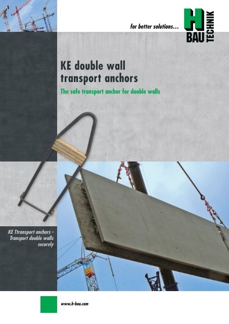
<strong>KE</strong> T<strong>transport</strong> <strong>anchors</strong> -<br />
Transport <strong>double</strong> <strong>wall</strong>s<br />
securely<br />
<strong>KE</strong> <strong>double</strong> <strong>wall</strong><br />
<strong>transport</strong> <strong>anchors</strong><br />
www.h-bau.com<br />
for better solutions…<br />
The safe <strong>transport</strong> anchor for <strong>double</strong> <strong>wall</strong>s
H-<strong>Bau</strong> <strong>Technik</strong> <strong>GmbH</strong><br />
Contact<br />
H-<strong>Bau</strong><br />
<strong>Technik</strong> <strong>GmbH</strong><br />
Head Office:<br />
Am Güterbahnhof 20<br />
79771 Klettgau<br />
Germany<br />
Tel. +49 (0) 77 42 / 92 15-20<br />
Fax +49 (0) 77 42 / 92 15-90<br />
eMail: export.klettgau@h-bau.de<br />
www.h-bau.com<br />
Production North-East:<br />
Brandenburger Allee<br />
14641 Nauen-Wachow<br />
Germany<br />
Tel. +49 (0) 332 39 / 775-20<br />
Fax +49 (0) 332 39 / 775-90<br />
eMail: export.berlin@h-bau.de<br />
Paul Rieger:<br />
Tel. +49 (0) 77 42 / 92 15-21<br />
Fax +49 (0) 77 42 / 92 15-93<br />
Mobil +49 (0) 171 / 864 72 61<br />
eMail: paul.rieger@h-bau.de<br />
Oliver Etzrodt<br />
Tel. +49 (0) 70 82 / 41 39 63<br />
Fax +49 (0) 70 82 / 79 33 00<br />
Mobil +49 (0) 171 / 864 72 60<br />
eMail: oliver.etzrodt@h-bau.de<br />
Rudolf Till<br />
Tel. +49 (0) 332 39 / 775-24<br />
Fax +49 (0) 332 39 / 775-90<br />
Mobil +49 (0) 172 / 993 70 50<br />
eMail: rudi.till@t-online.de
<strong>KE</strong> <strong>transport</strong> <strong>anchors</strong><br />
Contents<br />
<strong>KE</strong> <strong>transport</strong> <strong>anchors</strong> Transport <strong>double</strong> <strong>wall</strong>s more securely<br />
for better solutions...<br />
General 2<br />
Product range 3<br />
Dimensions 4<br />
Dimensional design values 5<br />
Planning 6-7<br />
Dimensional design 8-9<br />
Dimensional design examples 10-11<br />
<strong>KE</strong> IV dimensional design table 12<br />
1<br />
<strong>KE</strong> <strong>transport</strong> <strong>anchors</strong> - Transport <strong>double</strong> <strong>wall</strong>s securely
2<br />
<strong>KE</strong> <strong>transport</strong> <strong>anchors</strong><br />
General<br />
<strong>KE</strong> <strong>transport</strong> <strong>anchors</strong> - Transport <strong>double</strong> <strong>wall</strong>s more securely<br />
The Product<br />
<strong>KE</strong> <strong>transport</strong> <strong>anchors</strong> are used to erect<br />
and <strong>transport</strong> <strong>wall</strong> sections both during<br />
the production of the prefabricated<br />
part and at the site of<br />
construction.<br />
The <strong>KE</strong> I model <strong>transport</strong> anchor is especially<br />
suitable for small-area <strong>wall</strong>s<br />
up to ca. 4.00 m 2 ; the <strong>KE</strong> III model is<br />
designed for popular panel sizes and<br />
the <strong>KE</strong> IV model for panels with specific<br />
requirements.<br />
The variety of dimensions and the<br />
novel design make the <strong>KE</strong> <strong>transport</strong><br />
anchor an unrivalled product technically,<br />
economically and in relation to<br />
safety that clearly increases flexibility<br />
during the construction of prefabricated<br />
parts.<br />
www.h-bau.com<br />
Features<br />
GS mark (<strong>KE</strong> III) – for maximum<br />
possible safety<br />
Graduated bearing loads – for<br />
economic planning<br />
Quicker and simpler to install – for<br />
a problem-free production process<br />
Position can be planned independent<br />
of the formwork girders –<br />
for optimum solutions technically<br />
and economically<br />
Additional comments<br />
The <strong>KE</strong> I <strong>transport</strong> anchor is produced<br />
from 10 mm diameter steel, the <strong>KE</strong> III<br />
from 14 mm diameter steel and the<br />
<strong>KE</strong> IV from 16 mm diameter steel. The<br />
<strong>anchors</strong> can be supplied in widths of<br />
120 to 360 mm.<br />
The minimum concrete covering on<br />
the inside side of the shuttering is 10<br />
mm for the <strong>KE</strong> I and <strong>KE</strong> III models and<br />
on the outside 20 mm. For <strong>KE</strong> IV<br />
<strong>transport</strong> <strong>anchors</strong> a minimum concrete<br />
covering of 20 mm inside and<br />
outside must be maintained.
<strong>KE</strong> <strong>transport</strong> <strong>anchors</strong><br />
Product range<br />
for better solutions...<br />
<strong>KE</strong> <strong>transport</strong> <strong>anchors</strong> – the more secure and economic way to <strong>transport</strong> or erect <strong>wall</strong> sections during the production<br />
of the prefabricated part and at the site of construction.<br />
3 designs are available for different installation types:<br />
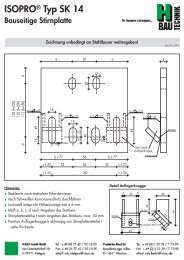
<strong>KE</strong> <strong>transport</strong> anchor model A<br />
<strong>KE</strong> <strong>transport</strong> anchor model B<br />
<strong>KE</strong> <strong>transport</strong> anchor model C<br />
The standard design.<br />
Positioned at the centre of gravity of<br />
the <strong>wall</strong> panels.<br />
Suitable for stationary productions/systems.<br />
Available as <strong>KE</strong> I, III and IV.<br />
* <strong>KE</strong> IV is designed with 2 stirrups<br />
For quick locking into the formwork<br />
girder<br />
The 90° stirrup leg makes it easier to<br />
secure the <strong>transport</strong> anchor to the<br />
formwork girder e.g. by means of<br />
spring steel binders. Can also be inserted<br />
at the point of gravity. Suitable<br />
for use in rotating systems.<br />
Available as <strong>KE</strong> III.<br />
Installed at right angles to the formwork<br />
girder.<br />
Care must be taken to ensure the<br />
anchor rods are positioned precisely<br />
and securely in the <strong>wall</strong> reinforcement.<br />
Caution: test position and secure<br />
hold of the timber struts.<br />
Available as <strong>KE</strong> III.<br />
3<br />
<strong>KE</strong> <strong>transport</strong> <strong>anchors</strong> - Transport <strong>double</strong> <strong>wall</strong>s securely<br />
*<br />
*
4<br />
Wall thickness d<br />
<strong>KE</strong> <strong>transport</strong> <strong>anchors</strong><br />
Dimensions<br />
Dimensions <strong>KE</strong> Transport Anchors<br />
Type<br />
www.h-bau.com<br />
<strong>KE</strong> I # <strong>KE</strong> III <strong>KE</strong> IV #<br />
Dimensions<br />
[mm]<br />
Dimensions<br />
[mm]<br />
Dimensions<br />
[mm]<br />
w l w l w l<br />
120 120 370 120 515 120 750<br />
130 130 370 130 515 130 750<br />
140 140 370 140 515 140 750<br />
150 150 370 150 515 150 750<br />
160 160 370 160 515 160 750<br />
170 170 370 170 515 170 750<br />
180 180 405 180 565 180 800<br />
190 190 405 190 565 190 800<br />
200 200 405 200 565 200 800<br />
210 210 405 210 565 210 800<br />
220 220 405 220 565 220 800<br />
230 230 405 230 565 230 800<br />
Determining the necessary anchor width w<br />
cv,inside<br />
cv,outside<br />
Horizontal reinforcement dsi Vertical reinforcement<br />
Transport anchor<br />
Horizontal reinforcement dsa<br />
Determining the necessary anchor width w:<br />
w = d - c v,i - c v,a - ds i - ds a<br />
<strong>transport</strong> anchor width w<br />
Vertical reinforcement<br />
Key:<br />
w = Transport anchor width<br />
d = <strong>wall</strong> thickness<br />
cv,i = concrete covering inside<br />
Formwork<br />
girder<br />
The determining is applicable if:<br />
The horizontal reinforcement is on the outside of the <strong>wall</strong> panel (1st position) if the horizontal reinforcement is inside (2nd position), the vertical<br />
reinforcement must be additionally removed.<br />
In general the following applies: anchor width w = formwork girder height FGH<br />
# The <strong>KE</strong> I and <strong>KE</strong> IV <strong>transport</strong> <strong>anchors</strong> are not a part of the GS mark.<br />
Type<br />
<strong>KE</strong> I # <strong>KE</strong> III <strong>KE</strong> IV #<br />
Dimensions<br />
[mm]<br />
Dimensions<br />
[mm]<br />
Dimensions<br />
[mm]<br />
w l w l w l<br />
240 240 405 240 565 240 800<br />
250 250 440 250 615 250 850<br />
260 260 440 260 615 260 850<br />
270 270 440 270 615 270 850<br />
280 280 440 280 615 280 850<br />
290 290 440 290 615 290 850<br />
300 300 440 300 615 300 850<br />
310 310 460 310 645 310 880<br />
320 320 460 320 645 320 880<br />
330 330 460 330 645 330 880<br />
340 340 460 340 645 340 880<br />
350 350 460 350 645 350 880<br />
c v,a = concrete covering outside<br />
d si = Horizontal reinforcement inside<br />
d sa = Horizontal reinforcement outside
<strong>KE</strong> <strong>transport</strong> <strong>anchors</strong><br />
Dimensional design values<br />
Transport anchor bearing load<br />
Concrete strength<br />
f c [N/mm²]<br />
Central pull 1)<br />
F red [kN]<br />
Diagonal pull ) *<br />
F red [kN]<br />
Transverse pull 2) *<br />
F red [kN]<br />
Diagonal pull<br />
90° 1) F red [kN]<br />
Additional geometric conditions<br />
Concrete covering on the outside<br />
c nom [mm]<br />
Installation<br />
Figure 1. Installation position in section<br />
<strong>KE</strong> I # <strong>KE</strong> III <strong>KE</strong> IV #<br />
25 35 25 35 # 25 35<br />
15.0 18.0 29.0 35.0 50.0 65.0<br />
15.0 18.0 29.0 35.0 50.0 65.0<br />
9.0** 11.0** 16.8 20.0 20.0 20.0<br />
— — 29.0 29.0 40.0 40.0<br />
Concrete covering on the inside<br />
c innen [mm]<br />
cnom<br />
cnom<br />
Mounting iron<br />
cinside ≥ 10mm<br />
<strong>KE</strong> <strong>transport</strong><br />
anchor<br />
cinside ≥ 10mm<br />
Minimum shuttering<br />
thickness min s* [mm]<br />
20<br />
≥ 10 mm<br />
≥ 20 mm 4)<br />
50<br />
25 55<br />
30 60<br />
4) Only applies to <strong>KE</strong> IV <strong>transport</strong> <strong>anchors</strong> with 200 mm widths per side in the anchor region.<br />
The <strong>transport</strong> anchor installation position<br />
is shown in Figures 1 and 2. The<br />
<strong>transport</strong> anchor must be secured in its<br />
position for the concreting process.<br />
This can be effected by securement to<br />
the bottom transverse reinforcement<br />
and a corresponding mounting iron at<br />
the top (see Figure 2).<br />
Transverse reinforcement<br />
Formwork<br />
girder<br />
Transverse reinforcement<br />
Figure 2. Installation position horizontal projection<br />
# The <strong>KE</strong> I, <strong>KE</strong> IV <strong>transport</strong> <strong>anchors</strong> and the concrete strength 35 N/mm² are not part of the GS.<br />
for better solutions...<br />
Installation tolerance: -10 mm formwork girder height<br />
1) Safety factor: γ = 3.0<br />
2) Safety factor: γ = 2.0; cnom = 30 mm ; for the orderly<br />
erecting of horizontal panels γ = 3.0.<br />
3) The admissible load capacities in dependence on<br />
the basic conditions such as concrete strength,<br />
concrete covering and <strong>transport</strong> variants are to be<br />
found in the assembly instructions approved by the<br />
Professional Trade Association for Building and<br />
Allied Trades<br />
* With diagonal and transverse pull there is increased<br />
load on the <strong>anchors</strong> (see p. 7 point 5)<br />
** Use square timber as erection aid (see Figure 3)<br />
With <strong>KE</strong> I <strong>transport</strong> <strong>anchors</strong> please<br />
note: A square timber is to be used<br />
where the load case is transverse pull<br />
(erecting a <strong>wall</strong> section) (see Figure 3).<br />
Square timber for erecting<br />
Figure 3. <strong>KE</strong> I transverse pull load<br />
5<br />
<strong>KE</strong> <strong>transport</strong> <strong>anchors</strong> - Transport <strong>double</strong> <strong>wall</strong>s securely
6<br />
<strong>KE</strong> <strong>transport</strong> <strong>anchors</strong><br />
Planning<br />
If more than two <strong>anchors</strong> are provided a compensating<br />
hanger or similar load distributing device must be used.<br />
The anchor spacings must be planned so that the <strong>wall</strong> can<br />
be lifted at its centre of gravity:<br />
Distance between centers <strong>KE</strong> I & <strong>KE</strong> III: e ≥ 300 mm<br />
Distance between centers <strong>KE</strong> IV: e ≥ 600 mm<br />
Distance to edge <strong>KE</strong> I & <strong>KE</strong> III: a ≥ 200 mm<br />
Distance to edge <strong>KE</strong> IV: a ≥ 400 mm<br />
www.h-bau.com<br />
For <strong>transport</strong> reasons, sections in excess of 3.00 m in<br />
height must in practice be turned at the site of construction.<br />
To this end the sections are to be put down flat and<br />
then raised to the upright position. The design criteria can<br />
be found in the assembly and usage instructions approved<br />
in the design specifications.<br />
Mounting reinforcement must be verified.<br />
The <strong>wall</strong> panels must be designed with a minimum reinforcement<br />
of Ø 6 / 250 mm in the anchor region.<br />
For the load case transverse pull, sufficient edging must<br />
be provided between the free edge and the <strong>transport</strong> anchor<br />
or a formwork girder in the anchor region.<br />
* The transverse pull load of the <strong>KE</strong> III <strong>transport</strong> anchor<br />
can be increased to 20 kN (concrete strength f c 25<br />
N/mm 2 ) if a 100 x 100 x 10 mm T-square is positioned<br />
on a width of 1.00 m per anchor. The square must be<br />
covered by an elastomer strip or shaft bearing.<br />
The steel section must be secured against falling (e.g.<br />
weld the steel stirrup and secure to crane hooks with<br />
cable).<br />
A square timber can also be used to protect the edge<br />
against damage caused by the crane hangers. This<br />
means a load increase can only be obtained in a limited<br />
manner.
<strong>KE</strong> <strong>transport</strong> <strong>anchors</strong><br />
Planning<br />
Determining the <strong>transport</strong> anchor load<br />
for better solutions...<br />
When carrying out the planning, the regulations in the assembly and usage instructions approved by the Professional<br />
Trade Association for Building and Allied Trades must be observed and maintained.<br />
When determining the loads working on the <strong>transport</strong> <strong>anchors</strong>, the following must be observed whilst taking possible<br />
load overlap into consideration:<br />
1. Dead weight of the prefabricated part<br />
2. Adhesion in the shuttering on lifting out<br />
3. mpact loads<br />
4. Number and arrangement of the <strong>transport</strong> <strong>anchors</strong><br />
5. Direction of force from means<br />
1. Dead weight:<br />
To determine the dead weight of the <strong>wall</strong> section, the load<br />
of the total volume of the shuttering is taken as 25.0<br />
kN/m 3 . Additional mounting parts must be considered separately.<br />
2. Adhesive forces:<br />
When raising the <strong>wall</strong> section out of the shuttering, consideration<br />
must be given to adhesive forces, the extent of<br />
which depends on the type and composition of the skin<br />
used. The following forces occur for conventional materials:<br />
Oiled shuttering: q = 1.0 kN/m²<br />
Painted shuttering: q = 2.0 kN/m²<br />
Rough timber shuttering: q = 3.0 kN/m²<br />
An adhesive force of q = 1.0 kN/m 2 has already been<br />
taken into consideration in the <strong>KE</strong> <strong>transport</strong> anchor load<br />
capacity tables.<br />
3. Impact loads:<br />
When lifting, depositing and <strong>transport</strong>ing <strong>wall</strong> sections impact<br />
stresses can occur. Their extent depends substantially<br />
on the type of hoisting equipment used and can be a multiple<br />
of the panel weight. The cranes used in the prefabrication<br />
process and also modern truck-mounted cranes<br />
have precision lifting equipment. Lifting load factors of f =<br />
1.1 to 1.3 are to be applied here. A lifting load factor of<br />
f = 1.3 has already been taken into consideration in the <strong>KE</strong><br />
<strong>transport</strong> anchor load capacity tables.<br />
To determine the lifting load coefficient under other basic<br />
conditions, the values must be determined according to<br />
DIN 1501 8-1: 1984-11.<br />
4. Number and arrangement of the <strong>transport</strong> <strong>anchors</strong><br />
Prefabricated concrete parts do not always have the ideal<br />
geometry of a rectangular panel with no recesses. Asymmetrical<br />
<strong>wall</strong> geometry and/or openings in the section<br />
produce different loads for the installed <strong>transport</strong> <strong>anchors</strong>.<br />
In this case, the distances from the centers of the <strong>KE</strong> <strong>anchors</strong><br />
to the <strong>wall</strong> section point of gravity are incorporated<br />
into the determining of the respective anchor load. Where<br />
there are more than two <strong>transport</strong> <strong>anchors</strong>, the mounting<br />
arrangement is statistically undefined. In this case, a roller<br />
compensation hanger is to be used. The higher number of<br />
<strong>anchors</strong> must not be used for the dimensional design without<br />
this measure.<br />
5. Direction of force from the lifting means (diagonal<br />
pull)<br />
If hangers are not used for <strong>transport</strong>, there is increased<br />
tensile load on the <strong>transport</strong> <strong>anchors</strong>. The maximum admissible<br />
angle of inclination α between the vertical and the<br />
lifting means is 45 degrees. The length of the lifting means<br />
is to be selected accordingly. This angle α = 45° has already<br />
been taken into consideration in the <strong>KE</strong> <strong>transport</strong><br />
anchor load capacity tables. The maximum admissible<br />
panel weight alters with the angle of inclination.<br />
7<br />
<strong>KE</strong> <strong>transport</strong> <strong>anchors</strong> - Transport <strong>double</strong> <strong>wall</strong>s securely
8<br />
<strong>KE</strong> <strong>transport</strong> <strong>anchors</strong><br />
Dimensional design<br />
Dimensional design of <strong>transport</strong> anchor systems<br />
When planning, the regulations in the assembly instructions must be observed and maintained.<br />
Transport <strong>anchors</strong> for <strong>double</strong> <strong>wall</strong>s must be dimensioned by an engineer for the forces actually occurring in practice.<br />
The loads to be taken into consideration are as follows:<br />
1. Dead weight of the <strong>wall</strong> section<br />
G = ρ x V<br />
2. Adhesion of the concrete part in the shuttering<br />
Ha = ha x A<br />
The shuttering adhesion Ha is absorbed by the transverse<br />
pull load capacity of the anchor F red . Where the shuttering<br />
is coarsely structured, the adhesive force increases considerably.<br />
An adhesive force of q = 1.0 kN/m 2 has already been<br />
taken into consideration in the <strong>KE</strong> <strong>transport</strong> anchor load<br />
capacity tables.<br />
www.h-bau.com<br />
α = angle of inclination<br />
β = angle of spead<br />
S = centre of gravity<br />
<strong>KE</strong> = <strong>KE</strong> <strong>transport</strong> anchor<br />
l = lifting means length<br />
The angle of inclination α must not exceed 45°. To this end, the<br />
length of the lifting means is to be l ≥ e/1 .41.<br />
Central pull = load in axial direction of the anchor<br />
Diagonal pull = load distribution under the angle of inclina-<br />
tion a relative to the vertical<br />
Transverse pull = load distribution at the end face when dou-<br />
ble <strong>wall</strong> is set upright. Extreme case 90°<br />
ρ = concrete gross density 25 kN/m³<br />
V = concrete volume of the two shutterings<br />
A = adhering shuttering face<br />
Shuttering type: ha<br />
Oiled shuttering 1 kN/m²<br />
Smooth timber shuttering 2 kN/m²<br />
Coarse timber shuttering 3 kN/m²
<strong>KE</strong> <strong>transport</strong> <strong>anchors</strong><br />
Dimensional design<br />
3. Impact load/lifting load factors<br />
F red = F admi / f<br />
Lifting gear<br />
Tower crane for<br />
construction<br />
Lifting load<br />
factor f<br />
1.3<br />
Truck-mounted crane 1.3<br />
Loading bridges,<br />
gantry crane<br />
Excavator, depending<br />
on the driving operation<br />
1.3<br />
2.0 - 2.5<br />
4. Number and arrangement of the <strong>transport</strong> <strong>anchors</strong><br />
F Av = G x b / (a + b)<br />
F Bv = G - F A<br />
Openings in the <strong>wall</strong> section or an asymmetrical geometry<br />
produce different loads on the <strong>anchors</strong>.<br />
5. Direction of force from the lifting means<br />
F res = F V / cos α<br />
F V = G / c<br />
Through the inclinedly engaging hangers, the force F resulting<br />
at the anchor, load-absorbing means and lifting<br />
means is increased in relation to the pure vertical force F V<br />
in dependence on the angle of inclination α of the force<br />
engagement. (The vertical force F V is produced from the<br />
weight, the arrangement of the <strong>anchors</strong>, the number of<br />
load-bearing <strong>anchors</strong> c and the acceleration forces etc.)<br />
An angle of inclination 0 ≤ α ≤ 45° has already been<br />
taken into consideration in the <strong>KE</strong> <strong>transport</strong> anchor load<br />
capacity tables. The max. admissible panel weight alters<br />
in dependence on the angle α.<br />
6. Verification for each load case and anchor<br />
F erf ≤ F admi<br />
for better solutions...<br />
The reduced anchor resistance F red includes the reduction<br />
through lifting load factors of a conventional tower crane,<br />
truck-mounted crane or gantry crane. If other lifting<br />
means are used, the lifting load factors will be higher.<br />
These are to be determined to DIN 15018-1: 1984-11.<br />
A lifting load factor of f =1.3 has already been taken into<br />
consideration in the <strong>KE</strong> <strong>transport</strong> anchor load capacity tables.<br />
FAv = Vertical force portion at anchor A<br />
FBv = Vertical force portion at anchor B<br />
G = Weight of <strong>double</strong> <strong>wall</strong> at point of gravity<br />
a = Distance from centre anchor A to the point of gravity*<br />
b = Distance from centre anchor B to the point of gravity *<br />
*see system diagram page 8<br />
G = weight<br />
F V = vertical force portion per anchor<br />
F res = resulting force per anchor<br />
c = number of load-bearing <strong>anchors</strong><br />
cos α = factor for diagonal pull<br />
F erf = resulting force from dimensional design per anchor<br />
F admi = bearing load per anchor<br />
9<br />
<strong>KE</strong> <strong>transport</strong> <strong>anchors</strong> - Transport <strong>double</strong> <strong>wall</strong>s securely
10<br />
<strong>KE</strong> <strong>transport</strong> <strong>anchors</strong><br />
Dimensional design example I<br />
Extract from the assembly iand usage nstructions – Page 14<br />
Transport without setting upright using lifting means<br />
Special load case B - Transport without setting upright<br />
Basic conditions:<br />
Number of <strong>anchors</strong>: 2 items<br />
Where this special load case is used, along with the specific accuracy and attention in<br />
planning and design, it must be ensured that the basic conditions set out in Chapter<br />
3.1 are implemented in an unrestricted manner.<br />
Concrete strength at the<br />
time of the <strong>transport</strong>: fc ≥ 25 N/mm²<br />
Shuttering density: 60 mm<br />
www.h-bau.com<br />
Transport with hanger – without setting<br />
the panel upright<br />
(α = 0°)<br />
Transport with lifting means – without<br />
setting the panel upright<br />
(0 < α ≤ 45°)<br />
<strong>KE</strong> III <strong>transport</strong> anchor bearing load<br />
Concrete covering: c nom = 20 mm<br />
Transverse<br />
pull<br />
Fred Diagonal<br />
pull<br />
Fred Central<br />
pull<br />
Fred Concrete<br />
strength f c<br />
Trasnport means lifting means: α = 45°<br />
[N/mm²] [kN] [kN] [kN]<br />
25 29.0 29.0 16.8<br />
35 35.0 35.0 20.0<br />
Safety coefficients γ according to Professional Trade<br />
Association Regulations for Building and Allied Trades<br />
for the present load case:<br />
Central pull/diagonal pull: γ = 3.0<br />
Transverse pull (no setting upright): γ no setting upright = 2.0<br />
admi. load capacity1) 1)<br />
GWall [to]<br />
Determining the admissible panel weight:<br />
Concrete compressive<br />
strength at time of <strong>transport</strong><br />
fc ≥ 25 N/mm²<br />
Concrete compressive<br />
strength at time of <strong>transport</strong><br />
fc ≥ 20 N/mm²<br />
Concrete compressive<br />
strength at time of <strong>transport</strong><br />
fc ≥ 15 N/mm²<br />
Angle<br />
α<br />
[degrees]<br />
2 * admin F * cos α / 10 [to] = 2 * 29.0*cos 45/10 = 4.10 to<br />
admin GWall ≤ → admin GWall = 4.10 to<br />
4 * admin Q / 10 [to] = 4 * 16.8/10 = 6.72 to<br />
2) cnom =<br />
30 mm<br />
2) cnom =<br />
25 mm<br />
2) cnom =<br />
20 mm<br />
2) cnom =<br />
30 mm<br />
2) cnom =<br />
25 mm<br />
2) cnom =<br />
20 mm<br />
2) cnom =<br />
30 mm<br />
2) cnom =<br />
25 mm<br />
2) cnom =<br />
20 mm<br />
s ≥ 50mm s ≥ 55mm s ≥ 60mm s ≥ 50mm s ≥ 55mm s ≥ 60mm s ≥ 50mm s ≥ 55mm s ≥ 60mm<br />
α = 0°<br />
4.1 4.5 4.5 4.7 5.2 5.2 5.2 5.8 5.8<br />
(hanger)<br />
α ≤ 45° 3.2 3.2 3.2 3.7 3.7 3.7 4.1 4.1 4.1<br />
where:<br />
admi F admissible central tensile load according to Table <strong>KE</strong> III in kN<br />
α angle according to diagram - load case<br />
admi. Q admissible transverse tensile load according to Table <strong>KE</strong> III in kN<br />
1) Already taken into consideration are: - lifting load factor - ψ = 1.3<br />
- direction of force from lifting means<br />
- adhesive forces - q = 1.0 kN/m2 (oiled steel shuttering)<br />
2) With different shuttering thicknesses s, concrete coverings cnom and shuttering strengths fc , the smaller load capacity produ-<br />
ced is decisive for the dimensional design.<br />
To make things easier, the admissible loading capacities are specified in the assembly<br />
and usage instructions according to the type of stress – see extract from the assembly<br />
and usage instructions:<br />
Special load case B – Transport without setting upright<br />
Minimum requirements: · two <strong>anchors</strong> per panel<br />
· shuttering thickness in the region of the <strong>transport</strong> anchor: 50 ≤ s ≥ cnom + 30<br />
· lifting cable length: l ≥ e/1.41<br />
where e = distance between centres of the <strong>transport</strong> <strong>anchors</strong>,<br />
α - design angle from direction of force of the lifting means – see drawing<br />
Note: Details in Sections 3 and 4 in particular are to be observed in the planning stage
<strong>KE</strong> <strong>transport</strong> <strong>anchors</strong><br />
Dimensional design example II<br />
Extract from the assembly iand usage nstructions – Page 13<br />
Transport mit Aufrichten mit Traverse<br />
Special load case A - Transport with setting upright<br />
Basic conditions:<br />
Number of <strong>anchors</strong>: 2 items<br />
Where this special load case is used, along with the specific accuracy and attention in<br />
planning and design, it must be ensured that the basic conditions set out in Chapter<br />
3.1 are implemented in an unrestricted manner.<br />
Concrete strength at the<br />
time of the <strong>transport</strong>: fc ≥ 25 N/mm²<br />
Transport with hanger<br />
(α = 0°)<br />
Transport with lifting means<br />
(0 < α ≤ 45°)<br />
Shuttering density: 60 mm<br />
<strong>KE</strong> III <strong>transport</strong> anchor bearing load<br />
Concrete covering: c nom = 30 mm<br />
Transverse<br />
pull<br />
Fred Diagonal<br />
pull<br />
Fred Central<br />
pull<br />
Fred Concrete<br />
strength f c<br />
Trasnport means lifting means: α = 0°<br />
[N/mm²] [kN] [kN] [kN]<br />
25 29.0 29.0 16.8<br />
35 35.0 35.0 20.0<br />
Safety coefficients γ according to Professional Trade<br />
Association Regulations for Building and Allied Trades<br />
for the present load case:<br />
Central pull/diagonal pull: γ = 3.0<br />
Transverse pull (with setting upright): γ with setting upright = 3.0<br />
admi. load capacity1) 1)<br />
GWall [to]<br />
Concrete compressive<br />
strength at time of <strong>transport</strong><br />
fc ≥ 25 N/mm²<br />
Concrete compressive<br />
strength at time of <strong>transport</strong><br />
fc ≥ 20 N/mm²<br />
Concrete compressive<br />
strength at time of <strong>transport</strong><br />
fc ≥ 15 N/mm²<br />
Ermittlung des zulässigen Plattengewichtes:<br />
Winkel<br />
α<br />
[Grad]<br />
2) cnom =<br />
30 mm<br />
2) cnom =<br />
25 mm<br />
2) cnom =<br />
20 mm<br />
2) cnom =<br />
30 mm<br />
2) cnom =<br />
25 mm<br />
2) cnom =<br />
20 mm<br />
2) cnom =<br />
30 mm<br />
2) cnom =<br />
25 mm<br />
2) cnom =<br />
20 mm<br />
2 * admin F * cos α / 10 [to] = 2 * 29.0*cos 0/10 = 5.8 to<br />
admin GWall ≤ → admin GWall = 4.5 to<br />
4 * admin Q / 10 [to] = 4 * 16.8 (2.0/3.0)/10 = 4.5 to<br />
s ≥ 50mm s ≥ 55mm s ≥ 60mm s ≥ 50mm s ≥ 55mm s ≥ 60mm s ≥ 50mm s ≥ 55mm s ≥ 60mm<br />
α = 0°<br />
2.7 3.1 3.5 3.1 3.6 4.0 3.5 4.0 4.5<br />
(Traverse)<br />
α ≤ 45° 2.7 3.1 3.2 3.1 3.6 3.7 3.5 4.0 4.1<br />
1) Already taken into consideration are: - lifting load factor - ψ = 1.3<br />
- direction of force from lifting means<br />
- adhesive forces - q = 1.0 kN/m2 (oiled steel shuttering)<br />
2) With different shuttering thicknesses s, concrete coverings cnom and shuttering strengths fc , the smaller load capacity produ-<br />
where:<br />
admi F admissible central tensile load according to Table <strong>KE</strong> III in kN<br />
α angle according to diagram - load case<br />
admi. Q admissible transverse tensile load corrected according to Table <strong>KE</strong> III with<br />
the factor of the safety γwith no setting upright /γwith setting upright = 2.0/3.0 in<br />
kN<br />
for better solutions...<br />
To make things easier, the admissible loading capacities are specified in the assembly<br />
and usage instructions according to the type of stress – see extract from the assembly<br />
and usage instructions:<br />
Special load case A – Transport with setting upright<br />
11<br />
<strong>KE</strong> <strong>transport</strong> <strong>anchors</strong> - Transport <strong>double</strong> <strong>wall</strong>s securely<br />
ced is decisive for the dimensional design.<br />
Minimum requirements: · two <strong>anchors</strong> per panel<br />
· shuttering thickness in the region of the <strong>transport</strong> anchor: 50 ≤ s ≥ cnom + 30<br />
· lifting cable length: l ≥ e/1.41<br />
where e = distance between centres of the <strong>transport</strong> <strong>anchors</strong>,<br />
α - design angle from direction of force of the lifting means – see drawing<br />
Note: Details in Sections 3 and 4 in particular are to be observed in the planning stage
12<br />
<strong>KE</strong> <strong>transport</strong> <strong>anchors</strong><br />
<strong>KE</strong> IV Dimensional design table<br />
Max. <strong>KE</strong> IV bearing loads in dependence on the concrete strengths<br />
Angle α<br />
[degrees]<br />
Basis: admissible<br />
central tensile<br />
force/anchor<br />
α = 0°<br />
(central pull)<br />
1) The following have already been taken into consideration: - lifting load factor - ψ = 1.3<br />
- direction of force from lifting means<br />
- adhesive forces - q = 1.0 kN/m 2 (oiled steel shuttering)<br />
- where 4 <strong>anchors</strong> are used per panel and the distances to the edge and between<br />
centers is maintained (see Ch. 3.2, Figure 3), the values specified in the Table<br />
can be increased by 50 %.<br />
2) With different shuttering thicknesses s, concrete coverings cnom and shuttering strengths fc the lower load capacity produced must be used in<br />
the dimensional design<br />
Minimum requirements: · two <strong>anchors</strong> per panel<br />
· shuttering thickness in the region of the <strong>transport</strong> anchor: 60 ≤ s ≥ cnom + 30<br />
· lifting cable length: l ≥ e/1.41<br />
where e = distance between <strong>transport</strong> anchor centers,<br />
α - design angle from direction of force of the lifting means – see drawing<br />
Note: The details in sections 3 and 4 in particular are to be observed in the planning.<br />
Concrete covering on the inside ≥ 20 mm on 200 mm width per side in the anchor region.<br />
www.h-bau.com<br />
15 N/mm²<br />
[kN]<br />
20 N/mm²<br />
[kN]<br />
admin Fα = Fu / 3 · cos α<br />
- per anchor -<br />
25 N/mm²<br />
[kN]<br />
30 N/mm²<br />
[kN]<br />
35 N/mm²<br />
[kN]<br />
44.1 50.9 56.9 62.3 67.3<br />
Inclined angle of pull, max. panel weight / anchor [kN]<br />
α = 15° 42.6 49.1 54.9 60.2 65.0<br />
α = 30° 38.2 44.1 49.3 54.0 58.3<br />
α = 45° 31.2 36.0 40.2 44.1 47.6
NOTES<br />
for better solutions...<br />
<strong>KE</strong> <strong>transport</strong> <strong>anchors</strong> - Transport <strong>double</strong> <strong>wall</strong>s securely
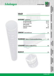
ISOPRO ®<br />
<strong>KE</strong>/SII<br />
RAPIDOBAT ®<br />
HED<br />
FERBOX ®<br />
BOXFER ®<br />
GRIPRIP ®<br />
PENTAFLEX ®<br />
RIPINOX ®<br />
PENTABORD ®<br />
WARMBORD ®<br />
SCHALBORD ®<br />
ZEMBORD ®<br />
SCHALL-ISO<br />
ACCESSORIES<br />
Balcony insulation elements<br />
Transport <strong>anchors</strong><br />
Shuttering tubes<br />
Shear dowels<br />
Reinforcement connectors<br />
Reinforcement connectors<br />
Masonry fixings<br />
Sealing technology<br />
Rustproof stainless steel<br />
Shuttering elements<br />
Shuttering elements<br />
Shuttering elements<br />
Shuttering elements<br />
Sound insulation elements<br />
Spacers<br />
www.h-bau.com<br />
Concreting with systems...<br />
H-BAU <strong>Technik</strong> <strong>GmbH</strong><br />
Am Güterbahnhof 20<br />
79771 Klettgau-Erzingen<br />
Germany<br />
Tel. + 49 (0) 7742 92 15-20<br />
Fax + 49 (0) 7742 92 15-90<br />
info.klettgau@h-bau.de<br />
Production North East<br />
Brandenburger Allee 30<br />
14641 Nauen-Wachow<br />
Germany<br />
Tel. + 49 (0) 3 3239 775-20<br />
Fax + 49 (0) 3 3239 775-90<br />
info.berlin@h-bau.de<br />
04/2009