PULTRUDED RAIL SYSTEM - Pentair Water Literature
PULTRUDED RAIL SYSTEM - Pentair Water Literature
PULTRUDED RAIL SYSTEM - Pentair Water Literature

Create successful ePaper yourself
Turn your PDF publications into a flip-book with our unique Google optimized e-Paper software.
<strong>PULTRUDED</strong> <strong>RAIL</strong> <strong>SYSTEM</strong><br />
INSTALLATION AND SERVICE MANUAL<br />
NOTE! To the installer: Please make sure you provide this manual to the owner of the equipment or to the responsible<br />
party who maintains the system.<br />
Item # E-03-359 | Part # 5625-359-1 | © 2012 <strong>Pentair</strong> Pump Group, Inc. | 10/30/12
2<br />
IMPORTANT!<br />
Read and follow these instructions<br />
for adjusting the pultruded rail<br />
system disconnect. Failure to<br />
follow these instructions may<br />
result in diaphragm leakage during<br />
pumping or guide rail damage.<br />
Step 1: If disconnect elbow<br />
and sealing flange were ordered<br />
separately, the proper diaphragm<br />
gap must be set. Complete factory<br />
assembled systems are factory<br />
preset and require no adjusting.<br />
Gap-setting Procedure:<br />
1) Loosen guide arms on each<br />
side of discharge elbow.<br />
2) Insert loose sealing flange into<br />
guide arms.<br />
3) To set the top 1/8" gap, insert<br />
the loose red rubber ring gasket<br />
in between the sealing flange<br />
and discharge elbow to act as<br />
a spacer.<br />
4) C-clamp sealing flange to<br />
discharge elbow to hold<br />
required gap (2 required,<br />
snug parts together without<br />
tightening).<br />
5) Rotate each guide arm<br />
to ensure the protruding<br />
"block" on each guide arm<br />
is up against the sealing<br />
flange rib and the guide arm<br />
opposite block side is against<br />
the sealing flange hanger rods.<br />
Torque bolts as follows:<br />
3" systems: 40 ft/lbs<br />
4" & 6" systems: 140 ft/lbs<br />
6) Remove c-clamp(s) and<br />
rubber gasket. Test gap by<br />
pulling out on bottom of the<br />
sealing flange. If the flange<br />
is adjusted properly, it should<br />
not pull back out of set<br />
position more than 1/16". Test<br />
disconnect by pulling up on<br />
eyebolt (sealing flange should<br />
release easily).<br />
Step 2: Attach supplied chain<br />
leg to achieve a three-point lift.<br />
Test the balance of the pump by<br />
adjusting the location of the<br />
shackle in reference to individual<br />
chain links. The pump must be<br />
level to function properly.<br />
WARNING: If the sealing flange<br />
end of pump is raised above<br />
the horizontal, the guide rail<br />
may be damaged upon lowering<br />
the pump. Ensure pump is<br />
horizontal before lowering the<br />
pump into basin.<br />
General<br />
Information<br />
Thank you for purchasing your<br />
Hydromatic ® pump. To help ensure<br />
years of trouble-free operation,<br />
please read the following manual<br />
carefully.<br />
Before Operation:<br />
Read the following instructions<br />
carefully. Reasonable care<br />
and safe methods should be<br />
practiced. Check local codes and<br />
requirements before installation.<br />
Attention:<br />
This manual contains important<br />
information for the safe use of<br />
this product. Read this manual<br />
completely before using this<br />
product and refer to it often for<br />
continued safe product use. DO<br />
NOT THROW AWAY OR<br />
LOSE THIS MANUAL. Keep<br />
it in a safe place so that you may<br />
refer to it often.<br />
Unpacking Pump:<br />
Remove pump from carton. When<br />
unpacking unit, check forconcealed<br />
damage. Claims for damage<br />
must be made at the receiving<br />
end through the delivery carrier.<br />
Damage cannot be processed from<br />
the factory.<br />
WARNING: Before handling<br />
these pumps and controls, always<br />
disconnect the power first. Do<br />
not smoke or use sparkable<br />
electrical devices or flames in<br />
a septic (gaseous) or possible<br />
septic sump.<br />
CALIFORNIA PROPOSITION<br />
65 WARNING:<br />
This product and<br />
related accessories contain<br />
chemicals known to the State of
California to cause cancer, birth<br />
defects or other reproductive<br />
harm.<br />
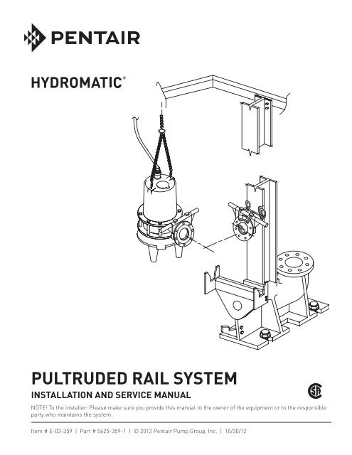
System Description:<br />
In a Hydromatic Pultruded Rail<br />
System, the pump is raised and<br />
lowered in the basin using a<br />
noncorrosive fiberglass I-beam.<br />
A unique, patented hydraulic<br />
sealing flange at the pump<br />
discharge allows the pump to<br />
be connected and removed from<br />
the discharge elbow with ease at<br />
any time without entering the<br />
wet well. There is no need to<br />
disconnect any piping or electrical<br />
connections to remove a pump for<br />
inspection or routine maintenance<br />
checks. A typical system will<br />
operate on float control switches.<br />
A bottom float control will turn<br />
off the pump(s). An additional<br />
float control per pump is then<br />
used to turn on the pump(s). In a<br />
multiple pump station, the pumps<br />
are automatically alternated<br />
if using a standard Hydromatic<br />
panel. Also, additional float<br />
controls may be used to<br />
indicate height and/or low<br />
water sump conditions. The<br />
general equipment for a<br />
simplex and duplex system<br />
includes the following:<br />
Simplex Duplex<br />
One pump Two pumps<br />
One discharge Two discharges<br />
Elbow assembly Elbow assemblies<br />
One hydraulic Two hydraulics<br />
Sealing flange Sealing flanges<br />
One guide rail Two guide rails<br />
One lifting chain Two lifting chains<br />
One door & Two doors &<br />
frame assembly frame assemblies<br />
Electrical Electrical<br />
controls controls<br />
Two level Three level<br />
controls controls<br />
Pump Not Operating<br />
or in Storage:<br />
Pumps with carbon ceramic seals<br />
must have impellers manually<br />
rotated (6 revolutions) after<br />
setting nonoperational for 3<br />
months or longer and prior to<br />
electrical start-up.<br />
Pumps with tungsten carbide seals<br />
must have impellers manually<br />
rotated (6 revolutions) after<br />
setting nonoperational for 3<br />
weeks or longer and prior to<br />
electrical start-up.<br />
Codes:<br />
All codes must be observed.<br />
Consult with the local inspector<br />
before installation to avoid<br />
costly delays. Hydromatic is not<br />
responsible for any expense<br />
incurred to meet local codes<br />
Installation<br />
Instructions<br />
1. Concrete Basin(s)<br />
Pour one or two concrete systems<br />
(one for pumps and control, etc.<br />
and one for valves, if required)<br />
or obtain precast concrete rings.<br />
A 45-degree slope may be poured<br />
around the inside perimeter of<br />
the basin at the bottom to<br />
prevent solids buildup providing<br />
the slope does not interfere<br />
with the discharge elbow and<br />
pump locations. Before beginning<br />
the installation, refer to the<br />
Installation Data as found in the<br />
Hydromatic Engineered Products<br />
Catalog.<br />
Follow the Installation Data<br />
taking into account the location<br />
of the discharge pipe, inlet pipe,<br />
controls, vent pipe, and anchoring<br />
requirements of the discharge<br />
elbow(s). (All of the above concrete<br />
work to be done by others.)<br />
2. Discharge Elbow Installation<br />
See Installation Data for the<br />
proper location of the discharge<br />
elbow on the basin bottom. Either<br />
cast 5⁄8" anchor bolts into basin<br />
bottom protruding 2" from basin<br />
floor with 5⁄8" lock washers and<br />
nuts securing, or drill holes for<br />
expansion lag screws to secure<br />
elbow to basin bottom. Each<br />
elbow requires four anchors (all<br />
furnished by others). Each elbow<br />
must be level. Length of anchors<br />
embedded in concrete varies<br />
with materials used, but must<br />
be sufficient to withstand the<br />
weight, torque, and thrust loads<br />
imposed by the pump.<br />
3. Discharge Piping<br />
(All supplied by others)<br />
Install vertical discharge piping<br />
modules to elbow using bolts,<br />
nuts, lock washers, and gasket.<br />
NOTE: When increasing<br />
the pipe size at the discharge<br />
elbow an eccentric flanged<br />
reducer coupling may be<br />
required to avoid interference<br />
with the guide rail. See<br />
Installation Data.<br />
Install remainder of the sump<br />
discharge piping. This typically<br />
includes a vertical run of<br />
piping appropriately sized and<br />
configured to mate with the<br />
vertical discharge piping, a ninety<br />
degree elbow, and a horizontal<br />
run of piping appropriately sized<br />
and configured to mate with the<br />
valve box or main piping. Install<br />
horizontal run extending through<br />
the wall of basin. Secure vertical<br />
run to the vertical discharge<br />
piping using the appropriate<br />
method (i.e., flange, weld,<br />
gasketed collar coupling) and<br />
grout all piping extending through<br />
basin walls.<br />
3
Installation<br />
Instructions<br />
NOTE: If using flanged<br />
connections, be certain that<br />
adequate clearances are<br />
provided throughout for the<br />
installation of bolts, nuts, lock<br />
washers, and gaskets.<br />
If total run of vertical piping<br />
exceeds twelve (12) feet, install<br />
a piping brace at the approximate<br />
midpoint of the piping. Secure<br />
brace (i.e., U-bolt with angle iron<br />
strap and angle iron extensions) to<br />
both piping and wall of basin.<br />
4. Basin Cover(s)<br />
The basin cover for the sump<br />
and valve box can either be<br />
poured concrete or precast.<br />
If Hydromatic door and frame<br />
assemblies are used, locate the<br />
concrete openings with respect<br />
to the discharge elbow mounting<br />
studs as shown in the Installation<br />
Data. If the covers are poured,<br />
place the door and frame assembly<br />
inside the concrete form and<br />
position per installation data.<br />
Anchor straps are provided on<br />
the door frames to secure them to<br />
the concrete. If precast covers are<br />
used, remove anchor straps from<br />
frame before installing into covers.<br />
Either cast four 3 ⁄8" anchor bolts<br />
into the top of the precast cover or<br />
drill holes for expansion lag screws.<br />
Use either 3 ⁄8" nuts or stainless<br />
steel bolts to secure door and frame<br />
assembly to cover. If valves are<br />
to be inside the wet well, provide<br />
access ways as required for the<br />
piping and valves to access piping<br />
shut-off valves (see Installation<br />
Data for general dimensions of<br />
access ways). Access ways must be<br />
covered and secured with tamperproof<br />
hardware (by others).<br />
4<br />
5. Guide Rail Installation<br />
Install the pultruded guide rail<br />
(I-beam) by attaching the lower<br />
end of the guide rail to the<br />
slotted lugs on the top side of the<br />
discharge elbow. Two 3 ⁄8" x 2"<br />
bolts, one rectangular washer, lock<br />
washers, and nuts are provided<br />
with the discharge elbow parts<br />
package. At the top of the guide<br />
rail, plumb and then fasten the<br />
guide rail to the door & frame<br />
assembly or other suitable<br />
bracket, using the four 1 ⁄4"<br />
x 1 stainless steel cap screws.<br />
If Hydromatic door and frame<br />
assemblies are not used, obtain<br />
suitable upper guide rail brackets<br />
(by others) to locate and support<br />
the rail(s). A flat surface 4" wide<br />
is required for each rail.<br />
6. Intermediate Guide<br />
Rail Bracing<br />
Sump depths of 9'6" and greater<br />
require intermediate guide rail<br />
bracing. The braces mount on<br />
the vertical discharge pipes with<br />
U-bolts which are sized according<br />
to the discharge pipe size. The<br />
number of guide rail braces<br />
required are as follows:<br />
Sump Depths<br />
9'6" to 18'0" 1 guide rail brace<br />
required<br />
18'6" to 27'0" 2 guide rail<br />
braces required<br />
27'6" to 30'0" 3 guide rail<br />
braces required<br />
On depths requiring more than<br />
one brace, space the braces<br />
equally on the pipe and tighten<br />
U-bolts. Match drill two 5 ⁄16" holes<br />
through the guide rail flange and<br />
attach with two 1 ⁄4" x 1" stainless<br />
steel bolts, nuts, and lock washers<br />
provided with braces. Install with<br />
bolt heads against the bracket.<br />
7. Exterior Piping<br />
Install the inlet hub(s) in side<br />
of basin and install inlet piping<br />
in hub and grout, or install inlet<br />
pipe(s) directly into basin and<br />
grout. Install drain pipe from<br />
valve box (if required) to basin.<br />
Slope pipe to give proper drainage<br />
to basin. Install vent piping in side<br />
of basin (if required). Extend<br />
piping to a proper elevation above<br />
grade (as required by plans and<br />
specifications and/or local codes).<br />
All piping furnished by others.<br />
See Installation Data for typical<br />
piping arrangement.<br />
8. Pump and Sealing Flanges<br />
Assemble the sealing flange (with<br />
arms) to the pump discharge<br />
flange using a gasket between the<br />
two. Screw nuts with lock washers<br />
on the bottom six studs. Slide<br />
the guide rail connector through<br />
the sealing flange ears and below<br />
the top two studs protruding<br />
through the back side of the pump<br />
flange. Place the retainer clips on<br />
the studs followed by lock washers<br />
and nuts and follow illustration.<br />
9. Pump Installation<br />
Check all piping braces and<br />
supports for proper installation<br />
and tightness. Attach the lifting<br />
chain assembly or cable to the<br />
lifting eye(s) on the top of<br />
the pump with the shackle(s)<br />
provided. Lower the pump into<br />
the basin with the guide rail<br />
connector engaged over the<br />
pultruded guide rail (I-beam).<br />
Ensure that the chain or cable<br />
does not interfere with the cord<br />
cap assembly. Attach the upper<br />
end of lifting assembly to the<br />
hook provided on the inside of the<br />
Hydromatic door and frame. The<br />
heavy rubber sealing diaphragm<br />
on the pump discharge should not<br />
touch the discharge elbow flange<br />
when the pump is being installed<br />
or removed, or is installed but not
unning. Its sole purpose is to flex,<br />
due to water pressure when the<br />
pump turns on, and form a leakproof<br />
seal between the pump and<br />
the discharge elbow.<br />
10. Float Switches<br />
Mount the float switch mounting<br />
bracket to the door and frame<br />
assembly using 3 /8" - 16" stainless<br />
steel screws. Include a dielectric<br />
gasket (by others) between<br />
dissimilar metals to avoid<br />
galvanic corrosion. Allow excess<br />
float cable to loop over mounting<br />
bracket. The sump level is<br />
controlled by Hydromatic<br />
float switch controls. The<br />
float is held in position in<br />
the sump by a weight attached to<br />
the power cord above the float.<br />
The cord supports the float and<br />
is adjusted for height from the<br />
surface. Duplex systems use three<br />
controls: one at all pumps off, one<br />
set at one pump on, and one set for<br />
both pumps on. Pumps alternate<br />
operation on each successive<br />
cycle with a Hydromatic Control<br />
Panel. The alarm level is usually<br />
set above the override (both<br />
pumps on) level so the alarm<br />
will signal only if the override<br />
level is exceeded. However, some<br />
engineers prefer to have the alarm<br />
set below the override level as it is<br />
possible for one pump to fail and<br />
the other to operate on the override<br />
level with the sump level never<br />
reaching the alarm level. Do not<br />
let floats rest against basin wall or<br />
bottom or entangle with each other<br />
or pump(s).<br />
11A. Control Panel on<br />
Mounting Stand<br />
When the Control Panel mounting<br />
stand is used, either cast four 1 ⁄2"<br />
anchor bolts into the concrete<br />
cover, or drill holes for expansion<br />
lag screws and attach stand<br />
(bolts or lag screws furnished by<br />
others). Insert power and sensor<br />
cords from the pumps and all<br />
float cords through the bushing in<br />
the sump cover. Bolt the panel to<br />
the panel stand. (Nuts, bolts, and<br />
washers are not supplied.) Make<br />
connections between the bottom<br />
of the control panel and the basin<br />
cover using flexible conduit and<br />
conduit seals (by others). When<br />
installing pump power cords,<br />
make certain that the cords do not<br />
rub against the pump or bottom of<br />
the basin. Shorten cords to suit the<br />
installation. See Bulletin Q-701<br />
for the Installation and Service<br />
Manual on the electrical Control<br />
Panel system.<br />
11B. Control Panel Mounted<br />
Remote from Basin<br />
If the Control Panel is remotely<br />
located, instead of on the mounting<br />
stand at the basin, install coupling<br />
through basin wall. Screw<br />
protective bushing from inside<br />
basin into coupling (all furnished<br />
by others). Make connections<br />
outside station using wiring,<br />
conduit seals (potted) and conduit<br />
to remotely located Control Panel<br />
(conduit and seals not furnished).<br />
Insert the power and sensor cords<br />
through the coupling provided<br />
with bushing. Grout in coupling<br />
going through sump wall (by<br />
others). When installing pump<br />
power cords make certain that<br />
cords do not rub against pump<br />
or on bottom of basin. Shorten<br />
cords to suit the installation.<br />
See Bulletin Q-701 for the<br />
Installation and Service Manual<br />
on the electrical Control Panel<br />
system.<br />
Electrical Connection:<br />
Make all connections in compliance<br />
with N.E.C. and/or local codes.<br />
Connect the control panel ground<br />
wire to a good ground. Ground<br />
wire must be grounded properly<br />
per N.E.C. and/or local codes. All<br />
electrical connections are to be<br />
made by a qualified electrician.<br />
Pump<br />
Operations<br />
WARNING: Before handling<br />
these pumps and controls,<br />
always disconnect the power<br />
first. Do not smoke or use<br />
sparkable electrical devices or<br />
flames in a septic (gaseous) or<br />
possible septic basin.<br />
See Pump Installation and Service<br />
Manual for submersible pump<br />
operation on starting system.<br />
Clean all trash and sticks from<br />
basin and connect pump to piping.<br />
Pump<br />
Maintenance<br />
Removing Pump from Basin for<br />
Servicing:<br />
WARNING: Before handling<br />
these pumps and controls,<br />
always disconnect the power<br />
first. Do not smoke or use<br />
sparkable electrical devices or<br />
flames in a septic (gaseous) or<br />
possible septic basin.<br />
To remove a pump from a<br />
standard installation (control<br />
panel mounted on basin cover),<br />
the power to the control panel is<br />
first turned off. Close the plug<br />
valve. Disconnect the power cords<br />
and sensor cords in the control<br />
panel from their terminals. Lift<br />
out the pump from the basin<br />
by means of the chain or cable.<br />
5
Disconnect the flexible conduit,<br />
power and sensor cords from the<br />
control panel. Pull the pump cord<br />
down through the pipe coupling<br />
while holding the cord on the<br />
underside of the basin cover so the<br />
cords do not fall into the basin. For<br />
reinstalling the pump, reverse the<br />
above procedure.<br />
Removing Float Controls<br />
for Replacement:<br />
To remove a float for replacement<br />
from a standard installation<br />
(control panel mounted on basin<br />
cover), the power is first turned off<br />
to the control panel. Disconnect<br />
the float leads from the terminals<br />
in the control panel. Disconnect the<br />
flexible conduit from the control<br />
panel. Remove the flexible conduit<br />
and the float control leads from the<br />
control panel. Pull the pump cord<br />
through the pipe coupling while<br />
holding the cords on the underside<br />
of the basin cover so the cords do<br />
not fall into the basin. Remove<br />
flexible conduit from potting<br />
head. Break out potting from the<br />
potting head and remove the float<br />
wire. Remove float cord from<br />
float cord mounting bracket and<br />
remove float from basin. Replace<br />
3900 float by reversing removal<br />
procedure. Repot the leads in<br />
the potting head according to<br />
N.E.C.and/or local codes.<br />
For the removal of the pumps<br />
and float controls from system<br />
with the control panel mounted<br />
remote from the basin cover,<br />
see the Pump Installation and<br />
Service Manual.<br />
WARNING: Before handling<br />
these pumps and controls, always<br />
disconnect the power first. Do<br />
not smoke or use sparkable<br />
electrical devices or flames in<br />
a septic (gaseous) or possible<br />
septic basin.<br />
6<br />
Pump<br />
Troubleshooting<br />
The following is a list of common<br />
problems and possible solutions.<br />
Refer to Pump Installation and<br />
Service Manual for any necessary<br />
adjusting, dismantling or repair<br />
work required on the pump.<br />
For Control Panel troubleshooting<br />
chart, refer to the Control<br />
Panel Installation and Service<br />
Manual Q-701.<br />
Pump runs but does not pump<br />
down the basin with the selector<br />
switch on either Hand or<br />
Automatic position.<br />
1. Impeller may be clogged.<br />
Amperage higher than name<br />
plate will indicate this.<br />
2. Pump rotation may be wrong.<br />
Reversing any two line leads<br />
on three phase pumps will<br />
reverse the rotation.<br />
3. Discharge plug valve may<br />
be closed.<br />
4. Plugging anywhere from<br />
impeller to sealing flange. This<br />
is evident if no water runs<br />
out of sealing flange after<br />
raising the pump. Pull the<br />
pump from the basin to find<br />
the clog.<br />
5. Plugging beyond the sealing<br />
flange. This is evident if water<br />
does run out when pump is<br />
operating when disconnecting<br />
the sealing flange from the<br />
discharge elbow. Remove the<br />
check valve, clean out cover<br />
and plug valve and other<br />
piping, if necessary, inside<br />
valve box to find clog.<br />
Reassemble all valves and<br />
piping. If the basin is still<br />
not pumped down after the<br />
pump is lowered again and the<br />
sealing flange is reconnected,<br />
proceed in a logical manner to<br />
locate and clear the plugging.<br />
6. Discharge head may be too<br />
high. Check elevation against<br />
design point of pump.<br />
7. Improper discharge flow.<br />
Check for correct impeller<br />
size and proper voltage.<br />
8. Check for possible broken or<br />
clogged forced main.<br />
Basin level is pumped down<br />
with selector switch on Hand<br />
position, but is not pumped<br />
down with selector switch on<br />
Automatic position.<br />
1. Floats are not hanging free in<br />
the basin or are covered with<br />
debris. Pump the level down<br />
with the selector switch on<br />
Hand, so that the floats can be<br />
observed. Relocate and clean<br />
all floats as necessary.<br />
2. If this is a new installation and<br />
original start-up, the floats may<br />
be miswired into the control<br />
panel. Recheck the wiring<br />
diagrams and schematics in<br />
the panel. If the start and stop<br />
floats are hooked in reverse,<br />
the pump will short cycle on<br />
and off and will not pump the<br />
level down.<br />
3. Floats or alternator are<br />
malfunctioning. Pull the floats<br />
out of the basin, clean them<br />
and lay them on the ground.<br />
Lift up the stop (lower) float in<br />
the left hand, the start (upper)<br />
float in the right hand and with<br />
the bulbs hanging free, turn<br />
selector switch to Automatic.<br />
Lower the left hand until the float<br />
hits the ground and lies on its<br />
side. Nothing should happen.<br />
After lowering the right hand<br />
in the same manner, the pump<br />
should start. When raising the
ight hand to suspend the float,<br />
the pump should continue to<br />
run. The pump should stop when<br />
raising the left hand to suspend<br />
the float. If this procedure<br />
does not cause the pump to<br />
operate as described, either order<br />
new float switches or replace<br />
alternator relay.<br />
<strong>PULTRUDED</strong> <strong>RAIL</strong><br />
<strong>SYSTEM</strong><br />
HYDRAULIC SEALING FLANGE<br />
ASSEMBLY WITH BUNA<br />
DIAPHRAGM<br />
STAINLESS<br />
STEEL GUIDE<br />
ARMS<br />
LIFTING CHAIN<br />
(OPTIONAL)<br />
GUIDE <strong>RAIL</strong><br />
CONNECTOR<br />
ACCESS FRAME<br />
<strong>PULTRUDED</strong> <strong>RAIL</strong><br />
I-BEAM<br />
FLANGE GUIDE<br />
RODS<br />
DISCHARGE FLANGE<br />
OF PUMP<br />
ZINC FACED<br />
FLANGE<br />
DISCHARGE<br />
ELBOW<br />
7
8<br />
D<br />
D<br />
DEPTH OF WELL (FT., IN.)<br />
ALL DIMENSIONS IN INCHES<br />
C<br />
J<br />
MIN. WATER<br />
LEVEL<br />
B<br />
B<br />
A<br />
LIFTING CHAIN<br />
VENT PIPING<br />
INFLUENT PIPE<br />
INV. EL.:<br />
SIMPLEX 3" THROUGH 6" PUMPS<br />
CONTROL/CABLE<br />
MOUNTING<br />
BRACKET<br />
HINGED SIDE<br />
E<br />
CONTROL/POWER CABLES<br />
� � SUMP<br />
DUPLEX 3" THROUGH 6" PUMPS<br />
A HINGED SIDE<br />
C<br />
C<br />
� � SUMP<br />
SUMP<br />
� � SUMP<br />
� � SUMP<br />
5/8" DIA BOLTS<br />
HYDROMATIC DUPLEX ALUM. HATCH<br />
G<br />
RIM ELEV:.<br />
GRADE ELEV.<br />
ELEV.<br />
G<br />
E<br />
E<br />
INTERMEDIATE GUIDE <strong>RAIL</strong><br />
SUPPORT - REQ. FOR DEPTHS<br />
EXCEEDING 9'-6"<br />
HYDROMATIC 3900 SUBMERSIBLE LEVEL SWITCHES<br />
FRP GUIDE <strong>RAIL</strong><br />
HYDROMATIC SOLIDS HANDLING SUBMERSIBLE PUMP<br />
HOPPER BOTTOM RECOMMENDED<br />
DISCH. ELBOW<br />
� � SUMP<br />
� � SUMP<br />
F<br />
F<br />
5/8" DIA BOLTS<br />
H
THIS PAGE INTENTIONALLY LEFT BLANK<br />
9
10<br />
THIS PAGE INTENTIONALLY LEFT BLANK
THIS PAGE INTENTIONALLY LEFT BLANK<br />
11
STANDARD LIMITED WARRANTY<br />
HYDROMATIC ® warrants its products against defects in material and workmanship for a period of 12 months from the date<br />
of shipment from Hydromatic or 18 months from the manufacturing date, whichever occurs first - provided that such products<br />
are used compliance with the requirements of the Hydromatic catalog and technical manuals for use in pumping raw<br />
sewage, municipal wastewater or similar, abrasive free non-corrosive liquids.<br />
During the warranty period and subject to the conditions set forth, Hydromatic, at its discretion, will repair or replace to th e<br />
original user, the parts which prove defective in materials and workmanship. Hydromatic reserves the right to change or<br />
improve its products or any portions thereof without being obligated to provide such a change or improvement for prior sold<br />
and/or shipped units.<br />
Start-up reports and electrical schematics may be required to support warranty claims. Submit at the time of start up<br />
through the Hydromatic website: http://forms.pentairliterature.com/startupform/startupform.asp?type=h.<br />
Warranty is effective only if Hydromatic authorized control panels are used. All seal fail and heat sensing devices must be<br />
hooked up, functional and monitored or this warranty will be void. Hydromatic will only cover the lower seal and labor<br />
thereof for all dual seal pumps. Under no circumstance will Hydromatic be responsible for the cost of field labor, travel<br />
expenses, rented equipment, removal/reinstallation costs or freight expenses to and from the factory or an authorized<br />
Hydromatic service facility.<br />
This limited warranty will not apply: (a) to defects or malfunctions resulting from failure to properly install, operate<br />
or maintain the unit in accordance with the printed instructions provided; (b) to failures resulting from abuse, accident or<br />
negligence; (c) to normal maintenance services and parts used in connection with such service; (d) to units which are not<br />
installed in accordance with applicable local codes, ordinances and good trade practices; (e) if the unit is moved from its<br />
original installation location; (f) if unit is used for purposes other than for what it is designed and manufactured; (g) to any<br />
unit which has been repaired or altered by anyone other than Hydromatic or an authorized Hydromatic service provider;<br />
(h) to any unit which has been repaired using non factory specified/OEM parts.<br />
Warranty Exclusions: HYDROMATIC MAKES NO EXPRESS OR IMPLIED WARRANTIES WHICH EXTEND BEYOND<br />
THE DESCRIPTION ON THE FACE HEREOF. HYDROMATIC SPECIFICALLY DISCLAIMS THE IMPLIED WARRANTIES OF<br />
MERCHANTABILITY AND FITNESS FOR ANY PARTICULAR PURPOSE.<br />
Liability Limitation: IN NO EVENT SHALL HYDROMATIC BE LIABLE OR RESPONSIBLE FOR CONSEQUENTIAL,<br />
INCIDENTAL OR SPECIAL DAMAGES RESULTING FROM OR RELATED IN ANY MANNER TO ANY HYDROMATIC<br />
PRODUCT OR PARTS THEREOF. PERSONAL INJURY AND/OR PROPERTY DAMAGE MAY RESULT FROM IMPROPER<br />
INSTALLATION. HYDROMATIC DISCLAIMS ALL LIABILITY, INCLUDING LIABILITY UNDER THIS WARRANTY, FOR<br />
IMPROPER INSTALLATION. HYDROMATIC RECOMMENDS INSTALLATION BY PROFESSIONALS.<br />
Some states do not permit some or all of the above warranty limitations or the exclusion or limitation of incidental or<br />
consequential damages and therefore such limitations may not apply to you. No warranties or representations at any time<br />
made by any representatives of Hydromatic shall vary or expand the provision hereof.<br />
USA<br />
740 East 9th Street, Ashland, Ohio 44805<br />
Tel: 419-289-3042 Fax: 419-281-4087<br />
Warranty Rev 12/11<br />
www.hydromatic.com<br />
– Your Authorized Local Distributor –<br />
CANADA<br />
269 Trillium Drive, Kitchener, Ontario, Canada N2G 4W5<br />
Tel: 519-896-2163 Fax: 519-896-6337