Bridges - ArcelorMittal
Bridges - ArcelorMittal
Bridges - ArcelorMittal

Create successful ePaper yourself
Turn your PDF publications into a flip-book with our unique Google optimized e-Paper software.
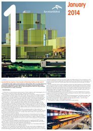
Long Carbon Europe<br />
Sections and Merchant Bars<br />
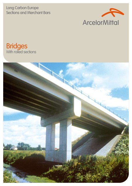
<strong>Bridges</strong><br />
With rolled sections
Ravine Petit-Etang,<br />
Ile de la Réunion<br />
Advanced Solutions for<br />
Rolled Beams in Bridge<br />
Construction
Contents<br />
1. <strong>Bridges</strong> with Rolled Sections 2<br />
2. <strong>ArcelorMittal</strong> Commercial Sections 4<br />
3. Steel and Composite <strong>Bridges</strong> 6<br />
4. Design and Appearance 8<br />
5. Composite <strong>Bridges</strong> 12<br />
6. Filler Beam Decks 20<br />
7. PreCoBeam <strong>Bridges</strong> 28<br />
8. Prestressed Composite Girders 29<br />
9. Half-through Girder Railway <strong>Bridges</strong> 31<br />
10. Truss Girder <strong>Bridges</strong> 35<br />
11. Footbridges and Cycle Track <strong>Bridges</strong> 37<br />
12. Finishing Work at <strong>ArcelorMittal</strong> Commercial Sections 42<br />
13. Pre-design Software ACOBRI 45<br />
14. Sustainable <strong>Bridges</strong> with the Use of Rolled Sections 46<br />
Technical Advisory & Finishing 48<br />
Your Partners 49<br />
1
1. <strong>Bridges</strong> with Rolled Sections<br />
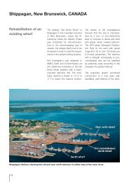
Footbridge at Bettembourg, Luxembourg –<br />
Single span bridge with a span of 37.5 m<br />
and a precambering radius of 150 m.
Roadbridge in Differdingen, Luxembourg – Bridge with a strong bending over the weak axis (see erection of two main girders on page 7).<br />
There are numerous partners involved<br />
when planning the construction of<br />
a new bridge. These include:<br />
• the decision-making bodies,<br />
• the residents affected by the construction,<br />
• the bridge owner; the architects and<br />
the engineers commissioned by him.<br />
These partners all contribute their<br />
own particular experience and ideas<br />
to the planning of a bridge.<br />
Footbridge over the Haken in<br />
Hamburg, Germany – Slender<br />
bridge with 4 spans of 25 m.<br />
This brochure outlines how <strong>ArcelorMittal</strong><br />
Commercial Sections (as a steel producer)<br />
can work with you during the early phases of<br />
planning the construction of a bridge. It provides<br />
precise suggestions and alternatives to put<br />
forward at an early stage which contribute to<br />
the optimisation of a construction project.<br />
Various methods for constructing short and<br />
medium span bridges are presented in this<br />
brochure. These cover footbridges and cycle<br />
track bridges, as well as road and railway bridges.<br />
The basic element shared by all the construction<br />
methods illustrated below is the use of<br />
rolled steel sections, in which <strong>ArcelorMittal</strong><br />
Commercial Sections is the market leader.<br />
3
2. <strong>ArcelorMittal</strong> Commercial Sections<br />
Rolling of a Histar beam in the rolling mill of Differdingen, Luxembourg<br />
<strong>ArcelorMittal</strong> Commercial Sections, one of<br />
the 5 business units of ARCELORMITTAL<br />
Long Carbon Europe, with plants in Spain,<br />
Poland, Czech rep, Romania, France, Italy<br />
and Luxembourg, is the largest European<br />
manufacturer of hot-rolled sections and has<br />
a wealth of experience on a world-wide scale<br />
in the production and use of these products.<br />
<strong>ArcelorMittal</strong> Commercial Sections rolls I-beams,<br />
channels, angles and sheet piles. The product<br />
range covers all sizes in the European standard<br />
series and a large number from the British,<br />
American and Japanese standard series.<br />
The largest standard section of <strong>ArcelorMittal</strong><br />
has a beam height of 1118 mm with a<br />
flange thickness of 45 mm. In addition,<br />
<strong>ArcelorMittal</strong> Commercial Sections also produces<br />
proprietary sized and “tailor made” sections.
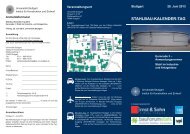
Road bridge over the<br />
A16 motorway, France<br />
5
3. Steel and Composite <strong>Bridges</strong><br />
The planning and construction of bridges<br />
has continually exercised a strong influence<br />
on the development of the construction<br />
industry. Numerous iron and steel bridges<br />
are milestones in this development. Some of<br />
these constructions have brought world-wide<br />
Multiple span viaduct at Ditgesbaach, Luxembourg<br />
recognition to their creators, whilst others to this<br />
day bear silent witness to their achievement.<br />
Nowadays, long span suspension bridges,<br />
cablestayed bridges, truss girder and composite<br />
bridges figure among the high points of bridge<br />
construction. In addition to the spectacular<br />
constructions, there are also innumerable<br />
short and medium span bridges which attest<br />
to these continuous developments and<br />
highlight the fact that steel is the best choice<br />
of material in the construction of bridges.
Advantages of Steel and<br />
Composite <strong>Bridges</strong><br />
Experience shows again and again that, in<br />
comparison with other solutions, steel bridges<br />
and composite bridges offer significant benefits:<br />
• they are economical, from the point of view<br />
of construction and operation, in addition to<br />
being well suited for easy, environmentally<br />
friendly, demolition and recycling;<br />
• they offer numerous possibilities in<br />
terms of architectural design;<br />
• they result in shorter construction times;<br />
• they are also suited to restricted<br />
construction depths;<br />
• they enable the approach ramps to be<br />
shortened, resulting in cost savings;<br />
• they help reduce construction costs, because<br />
the reduced weight of the bridges enables<br />
the use of smaller supports and foundations;<br />
• they can be easily adapted to the<br />
replacement of older superstructures and,<br />
on account of their reduced weight, enable<br />
the reuse of existing abutments, etc.;<br />
• they enable the industrial fabrication of<br />
construction components under strict<br />
quality control conditions in workshops<br />
sheltered from bad weather;<br />
• they seldom disrupt traffic circulation<br />
because the delivery and erection of<br />
the pre-fabricated steel parts can be<br />
carried out during off-peak hours;<br />
• they do not obstruct traffic because they do<br />
not require scaffolding or temporary supports;<br />
• they are easy to maintain, because the<br />
structural components are readily accessible<br />
for inspection and maintenance work;<br />
• they are flexible because they can be<br />
adapted at any time and at low cost to<br />
changes in requirements (for example,<br />
the widening of traffic lanes or the<br />
strengthening of the structure).<br />
Advantages of rolled girders in<br />
the construction of bridges<br />
Rolled girders, used in the construction<br />
of steel bridges and composite bridges,<br />
offer the following distinct advantages:<br />
3. Steel and Composite <strong>Bridges</strong><br />
Road bridge in Differdingen, Luxembourg - Erection of two main girders of a composite bridge by crane. The rolled<br />
girders are curved along both cross-sectional axes in order to adapt them to the geometry of the road.<br />
• industrial production in the form<br />
of high-quality standard products,<br />
offering superior availability;<br />
• cost savings due to minimal fabrication costs;<br />
• high fatigue resistance of the<br />
hot-rolled products;<br />
• availability of long pieces, reducing<br />
the number of site jointing;<br />
• possibility of carrying out finishing work<br />
in the rolling mill and consequently of<br />
delivering ready-to-install components<br />
to the construction site operations.<br />
7
4. Design and Appearance<br />
Footbridge in Saint-Quentin-en-<br />
Yvelines, France - Sophistically<br />
designed cable-stayed bridge.
With bridges, as with any construction project, the choice of<br />
construction materials is influenced or even decided on during<br />
the preliminary project phase. It is therefore essential at this stage<br />
to take into account the possibilities offered by the use of rolled<br />
sections, in order to reap the full benefits of construction using<br />
this method. Experience shows that the subsequent elaboration<br />
of counterproposals rarely leads to optimised solutions.<br />
During the preliminary planning phase, the specifications<br />
and the conditions which will have a decisive effect<br />
on the design of the bridge become clear:<br />
• high traffic loads must be safely and reliably carried<br />
over the whole service life of the bridge;<br />
• constraints, such as the geometry of the traffic lanes,<br />
the clearances, the construction depth, the angle of<br />
crossing, etc. demand suitably adapted solutions;<br />
• requirements with respect to the aesthetics of the<br />
construction work demand careful design;<br />
• the bridge must often be constructed under difficult<br />
conditions, within very tight deadlines and, as far as<br />
possible, without disrupting existing traffic circulation;<br />
• all forms of environmental pollution must be avoided;<br />
• the overall profitability of the project must be ensured, while<br />
taking into account not only the cost of the construction<br />
itself but also the indirect costs, such as maintenance costs<br />
and the cost of demolition at the end of its service life.<br />
The planning and design of a construction project constitutes<br />
a complex process and demands the full collaboration of all<br />
the partners involved, as well as calling upon their professional<br />
competence, In particular, there must be a good mutual<br />
understanding between engineers and architects.<br />
The purely technical and economical aspects are not dealt<br />
with here. They will be tackled in the following chapters<br />
where the different construction methods are presented.<br />
Road bridge in Calais,<br />
France - The abutments,<br />
bearing piles, load bearing<br />
structure, facing plates<br />
and guard rails form<br />
a harmonised enrity<br />
plates which lends to the<br />
aesthetic quality of the<br />
construction work.<br />
Aesthetics<br />
4. Design and Appearance<br />
In recent years, increasing demands have been made with respect<br />
to the aesthetics of bridges. This trend has also been seen with<br />
small construction works which do not come under the category<br />
of prestigious projects. A bridge should now be attractive to look<br />
at as well as functional. However, there is no standard solution for<br />
satisfying this requirement. Careful design must lie at the heart of<br />
every construction work and each project has its own parameters,<br />
within which the designer can exercise his creative freedom.<br />
The solution sought can be highly diverse, for example:<br />
• fitting the new construction to the surrounding<br />
environment, so that it does not dominate visually;<br />
• design of an architecturally uniform work, of<br />
which the bridge forms an integral part;<br />
• expression of the stand-alone quality of the bridge;<br />
• harmonisation of the structure with a given living space;<br />
• possibility of adapting the work to future developments.<br />
With rolled sections, the designer has at his disposal a very<br />
powerful tool. By making use of their basic properties - in<br />
particular high strength coupled with cost effectiveness<br />
- he can also include these in a visual statement.<br />
9
Rolled sections have a simple linear form and feature even<br />
surfaces. They lend a clean and precise form to the structure,<br />
which is enhanced by the fine aesthetic nuances of the different<br />
surfaces. Stiffeners, which are often seen as disruptive to the<br />
aesthetic harmony of a work, are in general not required due<br />
to the excellent static properties of these rolled sections.<br />
<strong>Bridges</strong> constructed using rolled sections are distinguished by<br />
their lightness. As the ratio of span to apparent deck depth is high,<br />
the bridges have a slender profile and the resulting impression of<br />
transparency plays a major role in the overall aesthetics of the work.<br />
4. Design and Appearance<br />
By bending the beams, it is possible to adapt them to the desired<br />
line. Moreover, the designer can make use of the possibilities to<br />
construct more pronounced curves, notably for footbridges.<br />
Structures built using rolled sections are visible and easy<br />
to “decipher “. The observer unconsciously visualises how<br />
the loads are carried by the structure and appreciates<br />
both the functionality and aesthetics of the work.<br />
The general form of a bridge is essentially conditioned by the form of its<br />
components and its proportions, in terms of span, construction depth,<br />
height of opening, and pier and abutment volumes.<br />
Footbridge near<br />
Schifflange, Luxembourg<br />
– Principle beams with an<br />
extreme curvature.
The characteristics of rolled sections offers great flexibility, which<br />
opens up numerous possibilities with respect to spans, slenderness,<br />
choice of line and reduced dead weight of the load bearing structure.<br />
The load bearing structure and other bridge parts should work<br />
in harmony. On account of their form and the visual quality of<br />
their surface, steel sections harmonise perfectly with guard<br />
rails, safety barriers, acoustic screens and face plates.<br />
Footbridge over the A13<br />
motorway at Soleuvre,<br />
Luxembourg – Design<br />
combining steel and colour.<br />
4. Design and Appearance<br />
Composite bridge with concrete<br />
crossbeams at Bentwisch, Germany –<br />
Design combining steel and colour.<br />
The visual impact of a construction work is often influenced to a large<br />
extent by the choice of colours used. In this field, endless possibilities<br />
for making an aesthetic statement are opened up by painting the<br />
metal. Following the development of new types of paint, this use<br />
of visual expression is today being used more and more often. The<br />
final result depends both on the choice of colours for the different<br />
components and on their harmonisation with each other and with<br />
the surrounding environment. Furthermore, if the bridge is repainted<br />
during the course of maintenance work, new colours can be used in<br />
order to give it an appearance which is at once new and different.<br />
11
5. Composite <strong>Bridges</strong><br />
Principle<br />
Composite deck construction consists of steel girders which support<br />
a reinforced concrete slab. Composite action is achieved by connecting<br />
both materials by shear studs. Transverse bracing over supports provides<br />
lateral restraint.<br />
Applications<br />
Road bridge over the A16<br />
motorway, France -<br />
Composite deck with<br />
two main girders in high<br />
strength steel S 460 M.<br />
Composite deck construction is recommended wherever construction<br />
depth is not, or only slightly, restricted. Feasible spans for<br />
road bridges range up to about 35m for simply supported<br />
spans and up to about 40 m for continuous spans.
Cross section<br />
For a narrow deck, two main girders are<br />
required. When the deck is wider or when<br />
construction depth is restricted, more<br />
than two girders will be needed.<br />
If an extraordinary torsional stiffness of<br />
the main beams is needed box sections<br />
can be used as alternative to single beams.<br />
These box sections are built from two<br />
parallel rolled girders joined longitudinal<br />
with a weld between the flanges or by a<br />
concrete infill in the chambers of the beam.<br />
Bridge link with two<br />
spans of 23.9 m to La<br />
Sarre, Luxembourg – The<br />
composite bridge is a<br />
twin-girder bridge with<br />
box sections of two<br />
longitudinally welded<br />
rolled beams.<br />
prefabricated reinforced<br />
concrete slab<br />
half cross-section over pier half cross-section within span<br />
Example of twin girder arrangement (cross section<br />
of A16 overbridge)<br />
Bridge link to La Sarre,<br />
Luxembourg - The large<br />
cantilevers have been<br />
designed to support the<br />
prefabricated concrete<br />
elements during construction<br />
without any scaffolding,<br />
the box sections have<br />
been designed to resist the<br />
resulting torsional moment.<br />
5. Composite <strong>Bridges</strong><br />
HL 1100 R<br />
S 420 M<br />
half cross-section over support half cross-section within span<br />
Example of a 6 girder arrangement (cross section<br />
of roadbridge, by-pass for the town of Luxembourg)<br />
13
Gosnat bridge in Vitry, France<br />
Statical system of main girders<br />
Girders of single span bridges are simply<br />
supported on the abutments. Multiple span<br />
bridges are designed either as successive<br />
simply supported or as continuous structures.<br />
Continuous girders are statically better<br />
suited: bending moments are lower and<br />
deflections are smaller. In addition they<br />
offer a major constructional advantage:<br />
the number of bearings and expansion<br />
joints, which cause high costs by the need<br />
for regular maintenance, is reduced.<br />
Continuity<br />
Depending on the overall bridge length and<br />
transport conditions the beams may be<br />
erected as unspliced pieces (delivered ex<br />
works in lengths up to 34 m or in exceptional<br />
cases up to 45 m) or site splicing will be<br />
necessary. In the latter case both splicing by<br />
butt welding and by bolting (high strength<br />
friction grip bolts) have proved successful.<br />
VDN bridge in Dakar, Senegal<br />
An alternative method consists in connecting<br />
the beams to a concrete cross girder<br />
through end plates and additional slab<br />
reinforcement (see page 15 Transverse<br />
bracing ensuring continuity).<br />
Cambering and bending of main girders<br />
Girders are cambered to compensate<br />
for deflections under permanent loads.<br />
Additional bending may be required to form<br />
the girders to the shape of the longitudinal<br />
profile. If the bridge is horizontally curved<br />
bending along the weak axis may be<br />
necessary. Both cambering and bending are<br />
carried out in the rolling mill on a press.<br />
Steel grades<br />
Steel with a yield strength of<br />
355 N/mm 2 (S 355) and more recently of<br />
460 N/mm 2 (S 460) are used primarily.<br />
With the latter type, special attention should<br />
be paid to the stiffness requirements.<br />
The use of S 460 high-strength steel in place of<br />
the more traditional S 355 results in a substantial<br />
reduction in weight and corresponding savings<br />
in material costs. Fabrication costs are also<br />
lower, with a full butt joint, for example,<br />
the weld volume is considerably reduced.<br />
Steel subgrades<br />
The use of fine grain structural steel is<br />
particularly advantageous: for example, grade S<br />
355 M/ML or grade S 460 M/ML in accordance<br />
with EN 10025-4 and HISTAR Trademark Steels.<br />
More information on HISTAR can be found on<br />
our website: www.arcelormittal.com/sections<br />
Shapes made from these low alloy fine-grained<br />
steel are produced using a thermo-mechanical<br />
rolling process with an increased cooling rate<br />
and subsequent self-tempering. These grades<br />
demonstrate excellent toughness at low<br />
temperatures and are characterised by their<br />
outstanding weldability. Due to the low carbon<br />
equivalent value, pre-heating is not required<br />
before flame cutting and welding.<br />
Also steels for low temperatures and<br />
weathering steels are available.
Transverse bracing at supports<br />
At supports, bracing is required to transfer<br />
horizontal loads to the bearings and to provide<br />
lateral and torsional restraint to the girders.<br />
Bracing is often designed to carry additional<br />
jacking loads in case of replacement of bearings.<br />
Bracing consists of:<br />
• either steel beams which are<br />
moment - connected to the main<br />
girders by bolting or welding<br />
• or reinforced concrete cross beams,<br />
where the reinforcing steel passes through<br />
drilled holes in the web of the longitudinal<br />
girders. Concrete cross beams are used<br />
with direct or indirect support.<br />
Road bridge in Bremgarten, Germany - With concrete<br />
cross beams and indirect support.<br />
longitudinal reinforcement<br />
main girder<br />
bearing<br />
shear studs<br />
end plate<br />
load distribution plate<br />
Concrete connection of main girders - Cross section<br />
through bracing (schematic)<br />
Structural<br />
steel<br />
weight<br />
( kg/<br />
m2)<br />
Mean span Lm (m)<br />
Composite road bridges. Structural steel weight per square meter of deck area.<br />
5. Composite <strong>Bridges</strong><br />
Railway bridge over the A23 motorway in Fretin, France - Four-span bridge with spans of 16.9 - 21.9 - 23.0 -<br />
17.8 meters. The two continuous main girders and the bracings within spans are rolled beams; the cross beams at<br />
supports are made of reinforced concrete.<br />
Transverse bracing ensuring continuity<br />
Reinforced concrete bracing over<br />
intermediate supports of multiple span<br />
bridges may be designed as splices of<br />
longitudinal girders. This construction method<br />
combines the following advantages:<br />
• the longitudinal girders are erected<br />
as single span girders;<br />
• there is no need for welded or bolted splices.<br />
Continuity is achieved by the use of vertical<br />
end plates and additional reinforcing bars in the<br />
deck slab. During concreting loads due to the<br />
dead weight of steel girders, formwork and wet<br />
Bridge in Schwedt, Germany - Concrete connection<br />
of main girders.<br />
concrete are carried by simply supported beams.<br />
After the concrete has hardened, moment<br />
resistance is provided at splices and subsequent<br />
loads are supported by continuous girders.<br />
Thus hogging bending is produced at supports<br />
only by super-imposed dead loads and variable<br />
actions. Forces are transmitted as follows:<br />
The compressive force is directed through<br />
the end plate from the lower flange to the<br />
concrete. The tensile force flows from the upper<br />
beam flange through the shear studs into the<br />
longitudinal slab reinforcement. Studs welded to<br />
the vertical end plates transfer the shear force<br />
from the steel beams to the concrete bracing.<br />
15
Intermediate transverse bracing<br />
Vertical loads are laterally distributed by the<br />
means of the deck slab. Bracing within the<br />
span is needed to stabilise the girders, but<br />
does not participate in load distribution.<br />
During construction, bracing prevents girders<br />
from lateral torsional buckling in sagging<br />
moment regions. After hardening of the<br />
Deck slab<br />
The deck consists of a non prestressed<br />
concrete slab with longitudinal and transverse<br />
reinforcement. Longitudinal reinforcement<br />
of continuous decks must be specially<br />
designed for crack width control.<br />
Hogging moments of two and three span bridges<br />
may be reduced by lowering the structure at<br />
intermediate supports after concrete hardening.<br />
Bearings and supports<br />
In general, simple elastomeric bearing pads are<br />
used with composite bridges. The advantage<br />
of the low construction weight of composite<br />
construction results in smaller dimensions<br />
for the sub-structure, including abutments,<br />
piers and foundations (in particular,<br />
pile foundations). The resulting savings<br />
in construction costs are characteristic<br />
for this construction method.<br />
Fabrication, transport and erection<br />
Fabrication consists of the finishing of the rolled<br />
beams, i.e. cutting to length, drilling, cambering<br />
or bending about the strong axis and, if required,<br />
about the weak axis, welding of shear studs<br />
and bearing plates, surface preparation and<br />
application of a corrosion protection system.<br />
concrete, the slab takes over this stabilizing<br />
action and bracing may be removed. With<br />
continuous girders, lateral buckling of the<br />
lower compression flange in hogging moment<br />
regions must be avoided. This is achieved using<br />
the bracing at the supports and, if needed,<br />
additional intermediate permanent bracing.<br />
New public transport system in Oberhausen,<br />
Germany - Crossing the DB railway line.<br />
Composite bridge over busy railway line<br />
in Choisy, France – A pair of ready-toerect<br />
girders are transported to the<br />
construction by rail.<br />
These operations can be carried out at the<br />
rolling mill’s finishing department in a both<br />
cost effective and time-saving process.<br />
Alternatively the work can also be carried out<br />
fully or partially in a steel fabricators’ workshop.<br />
The ready-to-erect girders are transported<br />
to the construction site by rail or by lorry.<br />
The single components are relatively<br />
light and therefore only low capacity<br />
lifting equipment is required on site.<br />
The girders are often pre-assembled in pairs<br />
in order to get erection units with increased<br />
stability. The girders or pairs of girders are<br />
lifted into final position by mobile cranes.<br />
Alternatively elements are assembled in a<br />
nearly area and subsequently launched.<br />
The low masses of steel components enable<br />
rapid assembly of the structure. In most cases,<br />
there is no need for temporary supports. When<br />
the routes crossed are in service, disruption to<br />
traffic can be kept to a minimum, especially if<br />
works are scheduled during off-peak hours.<br />
Composite bridge in Choisy, France –<br />
Lifting in of two pre-assembled girders<br />
early in the morning.<br />
Railway bridge over the A23 motorway<br />
in Fretin, France - Launching of the steel<br />
structure and assembled formwork.
The Horlofftalbridge in Hungen, Germany<br />
17
In-situ Concrete Slab<br />
The concrete slab can be cast in situ either<br />
on reusable formwork, or on precast<br />
concrete planks or profiled steel sheeting.<br />
If certain conditions relating to construction<br />
and reinforcement are complied with,<br />
the precast planks contribute to carrying<br />
loads in the transverse direction, together<br />
with in situ concrete. For cantilever parts,<br />
traditional formwork is generally used, with<br />
supports attached to the edge beams.<br />
5. Composite <strong>Bridges</strong><br />
Precast reinforced concrete panels used for permanent formwork. Example of formwork support for cantilever part of slab.<br />
C 30/37<br />
Concrete element<br />
Wire mesh<br />
Overlapping bars<br />
Prefabricated slab. Example of transverse joint detailing.<br />
Prefabricated Slab<br />
As an alternative to in-site concreting,<br />
precast deck elements can be used. The main<br />
advantage of this method consists in the<br />
reduction of the number of site operations and<br />
a substantial saving in the construction time.<br />
With twin girder - type bridges, the<br />
precast elements span the full width of<br />
the bridge as a single component. To allow<br />
connection with steel girders, slab elements<br />
may have pockets for shear studs.<br />
C 40/50 in-situ concrete<br />
Sealant<br />
The prefabricated elements are placed in<br />
a mortar bedding on the girder flanges.<br />
Alternatively support may be designed<br />
with a small gap between flange and<br />
slab which is later filled in with grout.<br />
Consequently transverse joints and<br />
pockets are filled with concrete to connect<br />
the slab to the steel structure.<br />
Hogging moments in continuous span girders can<br />
be reduced by lowering (jacking) the structure<br />
or intermediate supports after hardening of the<br />
concrete. The slab is prestressed longitudinally.<br />
Prefabricated slab – erection of a precast concrete<br />
element.
The Horlofftalbridge in Hungen (Germany) with eight spans constructed in 2006. For five spans partially prefabricated concrete beams with heavy rolled<br />
beams in S460 have been used.<br />
Prefabricated composite beams<br />
Short construction time is essential if<br />
disturbance to existing traffic should<br />
be minimized. This requirement is met<br />
through prefabrication of composite<br />
elements which are light, and therefore<br />
easy to handle and to transport.<br />
The main advantages of the prefabricated<br />
concrete flange hereby are:<br />
• Stabilizes beam (transport and construction),<br />
• Braces not needed for casting of concrete,<br />
• Scaffolding not necessary,<br />
• Stiffeners usually not required.<br />
The Horlofftalbridge in Hungen, Germany - Lifting in of a partially prefabricated beam.<br />
Further benefits for this type of construction are:<br />
• Steel contractor on-site superfluous,<br />
• Manufactured in workshop conditions,<br />
• Composite actions already in<br />
construction period.<br />
5. Composite <strong>Bridges</strong><br />
Thus the quality of the structure increases<br />
substantially. The elements can still be lifted and<br />
placed with a light-weight crane (compared<br />
to the heavy weight of pre-stressed concrete<br />
girders). The overall construction is extremely<br />
efficient and the construction time is optimized.<br />
19
6. Filler Beam Decks<br />
Bridge at<br />
Sète-Frontignan,<br />
France
Principle<br />
A filler beam deck consists of a concrete<br />
slab with stiff longitudinal reinforcement<br />
made of rolled beams and transverse<br />
reinforcement of steel bars.<br />
Closely spaced steel beams and concrete<br />
act compositely. Specific mechanical shear<br />
connection is not required provided that<br />
beams are cleaned to remove mill scale<br />
and that certain, mainly mill geometrical<br />
requirements, are met (refer to codes).<br />
Typical cross-section of a single track railway bridge.<br />
Multiple track railway bridge in Nienburg, Germany -<br />
The longitudinal profile of the road and the tracks<br />
greatly restrict the available construction depth.<br />
Formwork Transverse reinforcement<br />
Construction of a filler beam railway bridge as part<br />
of the Puymorens road tunnel link between France<br />
and Spain.<br />
Applications<br />
6. Filler Beam Decks<br />
Originally developed only for railway bridges,<br />
over the last few decades filler beam decks<br />
have also been widely and effectively used<br />
for road bridges. It offers a robust, simple and<br />
durable construction which does not require<br />
any highly specialised labour. Due to their high<br />
load carrying capacity, there are now a large<br />
number of decks of this type still in use even<br />
where the service conditions have changed.<br />
Filler beam construction is recommended:<br />
• for bridge decks with restricted<br />
or very shallow depths;<br />
• for bridges crossing roads with high traffic<br />
density: erection is both quick and easy;<br />
temporary supports and falsework are<br />
not required, so that disruption of traffic<br />
can be avoided to a large extent;<br />
• when replacing decks in existing structures:<br />
the shallow slab thickness facilitates<br />
adaptation to the geometrical constraints.<br />
Furthermore, the monolithic construction is<br />
also well suited to erection by launching.<br />
The span covered by filler beam decks range<br />
• up to 40 (50) meters for road bridges;<br />
• up to 30 (35) meters for railway bridges;<br />
(figures in brackets apply for<br />
continuous multiple span bridges).<br />
Multiple span filler beam bridge for the approach<br />
viaducts to the crossing of the high speed railway line<br />
LGV Est over the Moselle river.<br />
21
Overbridge at motorway Interchange in Fameck, France -<br />
Beams are bent horizontal to match road curvature.<br />
6. Filler Beam Decks
Filler beam deck bridge in Esch-sur-Alzette, Luxembourg - 19 m span; 0.65 m deck depth.<br />
For aesthetic reasons the edge beams are not encased in concrete on the outer side.<br />
Design<br />
Considering the bridge deck in the longitudinal<br />
direction, a composite structure is assumed<br />
for the design. In the transverse direction<br />
the deck behaves as a reinforced slab.<br />
For ultimate limit state, plastic moment<br />
resistance may generally be considered with<br />
concrete in tension being neglected. For<br />
the calculation of the deflections due to<br />
superimposed dead loads and live loads, a partial<br />
contribution of concrete in tension to flexural<br />
stiffness is taken into account. Fatigue strength<br />
of non-welded parts need not to be checked.<br />
Steel grades S 235, S 275 and S 355 are<br />
commonly used. For long spans, vertical<br />
deflection under traffic loads usually does not<br />
govern the design. Hence high strength grades<br />
S 420 and S 460 provide cost advantages.<br />
Beams<br />
Longitudinal reinforcement of the slab consists<br />
of rolled I-beams. The web spacing does not<br />
exceed 75 cm. A clear distance of at least 15<br />
cm between flanges is needed to allow pouring<br />
of concrete. The upper flange is encased in<br />
concrete with a cover of 7 to 15 cm, but<br />
not exceeding 1/3 of the nominal section<br />
depth. After completion of the deck, only the<br />
soffit of the lower flanges remains visible.<br />
Beams need to be cambered for two reasons:<br />
to compensate for dead load deflection<br />
and to allow the deck shape to follow the<br />
longitudinal profile of the road or track. In<br />
case of a curved deck supplementary bending<br />
about the weak axis may be required. Both<br />
cambering and bending may be carried out<br />
at the rolling mill’s finishing department.<br />
With multiple span bridges, structural continuity<br />
is generally preferred to simply supported<br />
decks. For this purpose beams are either:<br />
• delivered to site and erected in full<br />
length, if allowed for by production,<br />
transport and erection possibilities;<br />
• or spliced on site.<br />
Lower side of a filler beam deck - Only the bottom flanges of beams are visible.<br />
Connections may be carried out as bolted cover<br />
plate splices or as butt-welded splices. Usually<br />
they are located within spans at a section with<br />
low bending moment, and they are staggered.<br />
In order to maintain beams in position during<br />
concreting, spacers (for example threaded rods)<br />
should be provided. Stability against lateral<br />
torsional buckling under dead load (of steel and<br />
wet concrete) must be checked. Concreting<br />
may be carried out in more than one stage and/<br />
or transverse and plan bracing may be needed.<br />
23
Reinforcement<br />
In transverse direction non-prestressed<br />
reinforcing bars contribute to carry the loads.<br />
The lower bars are threaded through holes<br />
in the steel webs whereas the upper bars<br />
pass over the beams. Both reinforcements<br />
are anchored beyond the outer beams.<br />
Stirrups and reinforcing bars in longitudinal<br />
direction are added according to the statical<br />
requirement or for the control of cracking.<br />
Filler beam deck bridge in<br />
Amsterdam (Dutch State<br />
Railway Company).<br />
6. Filler Beam Decks<br />
Bridge for the high-speed<br />
track of the LGV Ouest,<br />
France
Bearings<br />
Simple elastic bearing pads are provided for<br />
each beam. The number of bearings may be<br />
reduced by the use of an integrated cross beam<br />
which requires additional reinforcement bars.<br />
Pont de Cyrnos in Senegal - Bottom view on the filler beam deck and support.<br />
Fabrication, transport and erection<br />
Fabrication consists in finishing of beams in a<br />
few simple operations which may all be carried<br />
out at the rolling mill’s finishing department:<br />
cutting to length, drilling of holes, cambering,<br />
welding of bearing plates (if any) and application<br />
of corrosion protection on lower flange.<br />
Pont de Cyrnos in Senegal -<br />
Detail of the support.<br />
6. Filler Beam Decks<br />
Beams are delivered to site ready for erection.<br />
Beam length may reach commonly 34 m.<br />
In exceptional cases they can be supplied<br />
(by rail) in lengths of up to 45 m. Due to low<br />
unit weight, only small cranes are needed.<br />
25
Railway bridge at Berchem, Luxembourg<br />
There are various proven methods for<br />
the construction of the bridge decks.<br />
These include the following:<br />
• lifting of beams into final position and<br />
assembling of spacers and bracing;<br />
• assembling of beams on an area<br />
located behind the abutment<br />
and subsequent launching;<br />
• erection of beams alongside final location<br />
on temporary supports, concreting of the<br />
deck and finally sliding into position.<br />
The last method is often used for<br />
the replacement of old decks.<br />
All these methods cause only minimal<br />
disruption to existing traffic.<br />
Railway bridge of the TGV Atlantique high speed line in<br />
Massy, France – Launching of the beams over the A10<br />
motorway interchange.<br />
Construction of an overbridge of A104 motorway, France – Falsework is not required.<br />
Disruption of motorway traffic is minimal.<br />
Formwork and concrete<br />
The formwork consists of prefabricated<br />
fibrecement or concrete planks which are<br />
placed on the lower flanges of the beams. A<br />
sealing mortar bed or rubber strip is used at the<br />
support. For the slab edges traditional formwork<br />
is attached to temporary supports. Prefabricated<br />
permanent formwork units may also be used.<br />
The space between beams is entirely filled<br />
up with concrete and the upper flanges are<br />
encased with a minimum cover of 7 cm.<br />
With deeper beams concreting is carried<br />
out in two or more steps with a first layer<br />
of at least 15 cm thickness. This helps<br />
to prevent beams from lateral torsional<br />
buckling. Temporary props are not needed<br />
and construction can be completed without<br />
disturbing traffic under the bridge.
Full moment rotation joint with botted cover plates.<br />
View on support. Assembled first span over the existing railway line.<br />
6. Filler Beam Decks<br />
Railway bridge at Sète-Frontignan, France -<br />
Lifting in of a pre-assembled part over<br />
an existing railway line.<br />
Railway bridge at Sète-Frontignan, France<br />
27
7. PreCoBeam <strong>Bridges</strong><br />
Cross Section alternative of the PreCoBeam designed by<br />
SSF Ingenieure, Munich.<br />
The PreCoBeam (Prefabricated Composite<br />
Beam) solution is a new bridge construction<br />
method invented in the beginning of the<br />
new millennium. It is again an example for<br />
economic bridge solutions with rolled beams<br />
and a high degree of prefabrication. This<br />
method is based on a rolled steel beam, oxycut<br />
longitudinally in two T-sections with a<br />
special shape. This shape works as a continuous<br />
shear connector which allows for the shear<br />
connection between profile and slab without<br />
the use of studs, and thus without any welding.<br />
PreCoBeam used for the bridge at Vigaun, Austria.<br />
Oxycutting of a rolled beam (HD 400x421 in S460)<br />
with the shark fin shape for the PreCoBeam bridge at<br />
Vigaun, Austria.<br />
After cutting, corrosion protection on the<br />
profiles on the parts exposed to the atmosphere<br />
in the final stage. In the next step reinforcement<br />
bars are placed through the cutting shape<br />
and a concrete top chord is concreted in<br />
the shop to produce a prefabricated bridge<br />
element. Subsequently the prefabricated<br />
bridge elements are transported to the site,<br />
placed on the abutments and, finally, the<br />
residual concrete chord is added on-site.<br />
The method is a very flexible solution offering<br />
various cross section possibilities according<br />
Lifting-in of a PreCoBeam for the bridge at Vigaun,<br />
Austria.<br />
Separation of a PreCoBeam in the finishing shop of<br />
<strong>ArcelorMittal</strong>.<br />
to the design requirements. As a result, the<br />
PreCoBeam, with the use of State-of-the-Art<br />
continous shear connectors and integrating<br />
the advantages of prefabricated element<br />
bridges, meet the following targets for<br />
competitive and sustainable construction:<br />
• high safety standard for vehicle<br />
impact, especially for bridges with<br />
only two girders (shock),<br />
• reduction of coating surface,<br />
• elementary steel construction<br />
nearly without any welding,<br />
• sparse maintenance and easy monitoring.<br />
The Vigaun bridge made of PreCoBeams with three<br />
spans of 26.15 m and a slenderness ratio of 1/23.
8. Prestressed Composite Girders<br />
Single span bridge in Kerpen Horrem, Germany - 41.25 m long HE 1000 A beams used for prestressed composite girders of “ Preflex “ type.<br />
Principle<br />
When a rolled beam is bent the tension<br />
flange is elastically stressed. In this state it<br />
is encased in concrete. Shear connections<br />
are provided for composite action.<br />
After hardening of the concrete, bending<br />
is released. The concrete part is thus<br />
compressed - it is prestressed.<br />
After erection on-site the other flange is<br />
connected to the concrete slab. By this<br />
procedure double composite action is given.<br />
A two-fold aim is achieved:<br />
• the concrete slab increases the bending<br />
capacity and stiffness of the girder;<br />
• under service load pre-compression stress in<br />
the concrete of the lower flange is reduced,<br />
but not totally. Thus no cracking occurs;<br />
concrete of the lower flange increases the<br />
flexural stiffness and reduces deflection.<br />
Applications<br />
Prestressed composite girders have:<br />
• a very high moment capacity; they are suited<br />
to the construction of bridges carrying<br />
heavy loads, in particular railway bridges;<br />
• a very high stiffness; deflections<br />
under service loading are small.<br />
Due to these properties, prestressed girders<br />
are particularly suited to structures when<br />
the available construction depth is highly<br />
restricted. The slenderness ratio value<br />
(ratio of the span divided by the structural<br />
depth) may reach 45 for road bridges.<br />
29
Fabrication of prestressed composite girder.<br />
Fabrication and Erection<br />
Beams are cambered at the rolling mill.<br />
At the fabrication shop shear connectors and<br />
additional cover plates (if any) are welded to<br />
the flanges. Then elastic bending, encasing of<br />
lower flange with concrete and prestressing<br />
are carried out as described above.<br />
cambered beam<br />
elastic bending<br />
lower flange is encased in concrete<br />
after hardening concrete is prestressed<br />
by releasing of bending load<br />
on site slab is cast and steel web<br />
is encased in concrete<br />
Most prestressed composite girders are simply<br />
supported beams. Sometimes girders are<br />
spliced at supports for continuous action.<br />
After erection of the prefabricated girders<br />
formwork elements are placed on the lower<br />
flanges. They are specially shaped for casting<br />
of the slab and simultaneous encasing of<br />
the steel webs. Thus a protective treatment<br />
against corrosion is not necessary.<br />
8. Prestressed Composite Girders<br />
If particularly high loads are to be carried (for<br />
example railway loads) prestressed composite<br />
girders may be arranged side by side. No<br />
formwork is needed. By encasing in concrete<br />
girders are integrated into a massive slab.
9. Half-through Girder Railway <strong>Bridges</strong><br />
Half-through girder<br />
railway bridge at Orgon, France<br />
31
Railway bridge over the Emile Mark street in Differdange, Luxembourg - The<br />
replacement of an old deck with direct track fastening by a ballasted track bridge<br />
required a structural system with minimized construction depth. A half-through<br />
girder deck solved the problem. The picture shows the assembled steel framework<br />
before concreting.<br />
Principle<br />
Main girders are arranged on both sides of the track. Their<br />
lower flanges support a floor with a ballasted track.<br />
Applications<br />
Half-through construction is appropriate if available construction depth<br />
is very small. Rolled beams used as main girders cover single spans<br />
up to about 16 m for standard track. For multiple track lines separate<br />
decks may be built without a need for increasing the track spacing.<br />
This construction method is suited for both the construction<br />
of new bridges and the replacement of existing decks. Also old<br />
decks with direct fastening of the track can be replaced in decks<br />
of modern form with ballasted track. Single span decks may<br />
be completely prefabricated and brought into position during<br />
temporary possession with minimal disruption to trains.<br />
9. Half-through Girder Railway <strong>Bridges</strong><br />
Reconstruction of the railway bridge over EmileMark street in Differdange,<br />
Luxembourg - Because of the very restricted construction depth, two single track<br />
half-through type bridges were implemented.<br />
Renovation of the platform in the main station in Zürich - The new<br />
5-span decks for ballasted track are of half through girder type<br />
with rolled beams and a reinforced concrete slab supported on lower<br />
flanges. Available time and space dictated the erection procedure.<br />
The 69 m long beams were lifted into position with portal cranes.<br />
This example shows a bow-string bridge for the Mediterranean high speed railway line over the French highway A7 near Avignon (F). A filler beam deck has been used to span<br />
transversally to the bridge axis.
Design and construction<br />
Main girders of short span are rolled beams. For longer<br />
spans built-up sections have to be used.<br />
The floor between the girders is of filler beam type. Rolled beams<br />
are arranged as cross girders in a close spacing and are encased in<br />
concrete. Only the lower flanges that carry the permanent formwork<br />
are left exposed. This method minimizes the construction depth of<br />
the floor which transfers the loads to the main girders. Filler beam<br />
floors are therefore well suited also for double track bridges.<br />
The inner side of the web of the main girder web is also encased<br />
in concrete. The resulting concrete trough maintains the ballasted<br />
track. For lateral stability of main girders, part of the cross beams<br />
are rigidly connected to the main girders to form U-frames.<br />
The floor may also be a common reinforced concrete slab. A few cross<br />
beams and bracing are then required for stability during construction.<br />
The prestressing method described may be applied to the main girders and the encasing slab in order to<br />
reload the concrete (SNCB-NMBS system). The resulting structure is extremely stiff.<br />
Extension of the Brussels - South Station for the Eurostar trains - A launching gantry<br />
is used for fast erection of prefabricated prestressed composite decks.<br />
9. Half-through Girder Railway <strong>Bridges</strong><br />
LGV Est bridge, France<br />
A half-through girder deck during launching. It carries the new Mediterranean High<br />
Speed Railway Line which was opened to traffic in 2002. The exposed flanges of the<br />
transverse filler beams can be seen at the bottom side. The blue coloured part is the<br />
launching nose.<br />
Rolled beam bent<br />
for prestressing<br />
Concrete (1st stage)<br />
Tension cable<br />
Ballasted track<br />
Concrete<br />
(2nd stage)<br />
Typical cross-section of a half-through prestressed composite deck - This system<br />
of prefabricated deck has been developed by the National Belgian Railway Company<br />
(SNCB-NMBS).<br />
33
La Savoureuse bridge, France
10. Truss Girder <strong>Bridges</strong><br />
Steel truss girders are particularly well suited to the construction<br />
of medium span bridges, offering high strength and stiffness<br />
combined with low dead weight. They consist of slender elements<br />
opening up a wide range of possibilities in terms of overall<br />
shape and resulting in a light and transparent structure.<br />
Steel trusses have also proved effective and economic<br />
in the construction of short span bridges in remote<br />
sites which are not readily accessible. The low weight of<br />
components greatly facilitates transport and erection.<br />
Design and construction<br />
The easiest arrangement of the deck is at top chord level. The concrete<br />
deck slab, if connected to the steel girders, acts compositely.<br />
If available construction depth is limited, through<br />
or half-through arrangements are chosen.<br />
Reconstruction of the bridges over the Muota river,<br />
Gotthard -line of the Swiss Federal Railway Company -<br />
Diagonals and upper chords are made of rolled beams<br />
(HD and HE shapes). Thermomechanically rolled steel<br />
was used for enhanced weldability.<br />
Nowadays, parallel chord trusses are often preferred. Typically diagonals<br />
are inclined at the same angle. There are no verticals. Connections<br />
are standardised as far as possible for cost-effective fabrication.<br />
An alternative method to traditional design of truss member<br />
connections arises from the geometric properties of rolled beams.<br />
35
Chord and diagonal sections with different sectional areas but<br />
the same inner depth between flanges are arranged in a way to<br />
allow butt welding of flanges without requiring gusset plates.<br />
Rolled beams are most appropriate for chords and diagonals:<br />
they are produced industrially with a high quality standard and<br />
are available at low cost and in a wide range of sizes. As a hot<br />
rolled product they have a good fatigue resistance. They may<br />
easily be hot dip galvanized for corrosion protection.<br />
The open shape of rolled beams facilitates connections. The wide<br />
flange beams, and especially the HD 360 and HD 400 shapes,<br />
have a high buckling resistance which is particularly required for<br />
compression members. Available flange thicknesses of these<br />
shapes range from 18 to 125 mm. All rolled sections can be<br />
delivered in high quality steel grades with high yield strength,<br />
good toughness properties and excellent weldability.<br />
Bridge over the Alzette river in Cruchten, Luxembourg – Transparent<br />
truss structure in composite action without gusset plates – S460<br />
rolled steel sections have been used as truss members.<br />
10. Truss Girder <strong>Bridges</strong><br />
Costa Martina road bridge, Spain - Rolled beam truss girders, continuous over 3 span<br />
of 60.6 - 121.2 - 60.6 m. The picture shows the bridge before the erection of the<br />
precast slab elements on the upper chords.
11. Footbridges and Cycle Track <strong>Bridges</strong><br />
Footbridge over the<br />
expressway at Soleuvre,<br />
Luxembourg<br />
37
Pedestrian crossing of<br />
Kirchberg, Luxembourg<br />
Conceptual design of footbridges and<br />
cycle track bridges is often governed by<br />
requirements which are not purely functional<br />
such as span and intended use. Integration<br />
to the environment, alignment to existing<br />
footpaths or cycle tracks, arrangement of<br />
access ramps, possible adding of a roof are<br />
all factors which can exercise a determining<br />
influence on the choice of the structure type.<br />
Hence the wide range of requirements with<br />
respect to design and aesthetics results in a<br />
number of possible forms of construction.<br />
The floor may be arranged at the top level of<br />
the structure or at lower level if the structure<br />
is of the through or half-through type.<br />
Main girders may be straight or curved.<br />
Bottom view on the footbridge at<br />
Soleuvre, Luxembourg – Sheet piles<br />
are used for the abutments.
Footbridge for the visitors of a leisure park in Wavre, Belgium - Through type bridge with thematic enclosure.<br />
Footbridge over the national road at Wasserbillig, Luxembourg<br />
Floor at top level<br />
Most frequently the floor slab is<br />
supported by two main girders.<br />
Wooden decks have proved successful with<br />
small spacing of girders. Steel cross beams and<br />
bracings are then required. A reinforced concrete<br />
floor offers the advantages of composite<br />
construction if connected structurally to the<br />
steel girders. For narrow decks precasting<br />
of slab units speeds up construction.<br />
Design and detailing are similar to those<br />
for road bridges. Girder dimensions are<br />
comparatively smaller and the span range<br />
covered with rolled beams is wider.<br />
Bottom view on the twin-girder, composite footbridge<br />
at Wasserbillig, Luxembourg<br />
11. Footbridges and Cycle Track <strong>Bridges</strong><br />
39
Access footbridge to the building of the Court of Justice of the European Communities, Luxembourg - Architectural design based on lattice girders.<br />
Half-through construction<br />
Half-through cross sections with the floor at<br />
bottom level are often used because the shallow<br />
construction depth provides the shortest lengths<br />
of ramps. Main girders may also act as a parapet.<br />
Cross beams are rigidly connected to<br />
main girders for lateral stabilization<br />
through U-frame action.<br />
The cross beams carry the floor made of<br />
wooden or steel planks, precast concrete units or<br />
in-situ concrete cast on permanent formwork.<br />
Horizontal bracing is located underneath.<br />
Transport and erection<br />
Main girders, cross beams and bracing are<br />
usually transported to site as individual<br />
components. Long beams are site spliced.<br />
The bridge may be erected in final position<br />
or alternatively be completely assembled<br />
next to the final site and then lifted or<br />
launched into position in one unit. The<br />
last method requires heavier equipment<br />
but permits very fast erection with<br />
minimal disruption to existing traffic.<br />
Equipment<br />
Footbridges are looked at from both short<br />
and long distances. Therefore the design for<br />
appearance of equipment, such as parapets,<br />
lighting, etc. are particularly important.<br />
Footbridges built to interconnect buildings<br />
are mostly of the covered type. A lattice<br />
girder form with the roof attached to<br />
the top chords is then suitable.<br />
Other construction types<br />
For different reasons other construction types<br />
may be used: suspended, cable stayed, truss,<br />
arch, etc. For all types the wide range of rolled<br />
sections offers a variety of design possibilities.<br />
Conclusion<br />
The use of rolled beams in the construction<br />
of footbridges and cycle track bridges<br />
offers a number of advantages: simple<br />
design, low fabrication costs, fast<br />
erection, minimized disruption to existing<br />
traffic, attractive forms and colours.<br />
Erection of half-through type<br />
structure - Pre-assembled<br />
framework including permanent<br />
steel shuttering is lifted into<br />
position by crane.
Footbridge over the Sûre at Steinheim, Luxembourg<br />
View on the wooden walkway of the half-through bridge with<br />
rolled sections in Steinheim, Luxembourg<br />
Bottom view on the stiffening elements<br />
of the bridge in Steinheim, Luxembourg<br />
41
12. Finishing Work at <strong>ArcelorMittal</strong><br />
Commercial Sections<br />
Cutting of PreCoBeams<br />
with the full-automatic<br />
oxy-cutting process in the<br />
finishing workshop.
Finishing workshop - Cambering of bridge girders on<br />
the press.<br />
The finishing workshop at <strong>ArcelorMittal</strong><br />
Commercial Sections is equipped to fabricate<br />
long lengths, heavy rolled beams, and in<br />
particular for operations required in the<br />
manufacture of bridge girders. These including<br />
sawing, bending about one or both main axes,<br />
the welding of shear stud connectors and end<br />
12. Finishing Work at <strong>ArcelorMittal</strong> Commercial Sections<br />
Finishing workshop - Welding of shear stud connectors. Automatic surface treatment equipment - Shot blasting<br />
and protective coating of beams.<br />
plates, and the drilling of the web and flanges.<br />
Longitudinal cutting, notching, machining<br />
and welding work can also be carried out.<br />
Surface treatment by shot blast cleaning and metal<br />
spraying or the application of partial or full paint<br />
systems can also be carried out in the factory.<br />
In this way, steel components can be<br />
delivered directly from the rolling mill to<br />
the site, resulting in reduced costs and<br />
improved construction deadlines.<br />
43
Surface Treatment<br />
In addition to the significant aesthetic function (see chapter Design and Appearance)<br />
surface treatment has to provide an effective protection against corrosion.<br />
The following are conditions for a durable protection:<br />
• careful surface preparation<br />
• controlled application of the protective coating<br />
• regular inspection during the life of the bridge and immediate repair of any damage.<br />
Over the last few years, much progress has been made with respect to paint formulations,<br />
their application, their durability and their environmental friendliness. In general,<br />
modern coating systems last for at least 20 years before major maintenance.<br />
Surface preparation<br />
Blast clean SA 3<br />
Coatings<br />
Example of protective treatment for composite decks.<br />
Protective coating systems<br />
The choice of a suitable system and<br />
the correct application are essential<br />
for effectiveness and durability.<br />
The available protective systems<br />
include the following:<br />
• painting<br />
• metal spraying<br />
• hot-dip galvanizing<br />
• galvanizing + painting (duplex system)<br />
Primer and intermediate coat to be applied in the workshop, top coat on site,<br />
after completion of deck slab.<br />
12. Finishing Work at <strong>ArcelorMittal</strong> Commercial Sections<br />
Surface preparation<br />
Example of protective treatment for filler beam decks.<br />
Whole surface of beam: blast clean SA 2 1/2<br />
Lower flange: blast clean SA 3<br />
Coating of lower flange<br />
Filler beam bridge built over a heavy traffic railway line -<br />
High quality coating provides durable protection to<br />
lower flanges.<br />
A number of aspects have to be considered<br />
for the choice of the appropriate system: type<br />
and expected life of the bridge, local climate<br />
and other environmental site conditions,<br />
constraints relating to maintenance, possibilities<br />
of surface preparation and painting, metal<br />
spraying or galvanizing at workshop, and<br />
feasibility of applying the final coating on site.<br />
Steel components which are encased in<br />
concrete do not require coating. However<br />
transition zones must be carefully designed.<br />
It is recommended to carry out as much<br />
of the surface treatment as possible in the<br />
controlled environment of a workshop.<br />
Usually only the finishing coat is applied after<br />
erection on site. Here, rolled beams can offer<br />
the advantage of already being coated with<br />
the required systems in the rolling mill.<br />
Primer and intermediate coats to be applied in the workshops,<br />
top coat on site after concreting
13. Pre-design Software ACOBRI<br />
ACOBRI (<strong>ArcelorMittal</strong> Composite <strong>Bridges</strong>)<br />
is a pre-design software for composite<br />
bridges with a superstructure based on rolled<br />
sections. ACOBRI applies to road-, railway-<br />
and footbridges with single as well as multiple<br />
spans. Various alternatives of cross-section<br />
types like conventional deck, deck with<br />
prefabricated composite beams, box girder<br />
deck, concrete-filled box girder and fillerbeam<br />
deck are included. The pre-design is<br />
carried out according to the French, German<br />
or Eurocode (EN) regulations. The software is<br />
available as French, English and German version.<br />
Please check our website for download<br />
and recent updates of our software:<br />
www.arcelormittal.com/sections<br />
45
14. Sustainable <strong>Bridges</strong> with<br />
the Use of Rolled Sections<br />
Sustainable bridges with the<br />
use of rolled sections<br />
The preservation of natural resources in our<br />
industrialized societies has become priority<br />
in creation of built environment. As a result,<br />
construction concepts have to comply with<br />
changing economical parameters like the<br />
incorporation of life cycle analyses in the design<br />
of structures as well as with technological<br />
changes in considering sustainability goals in<br />
respect to the environment and society.<br />
These sustainability goals are in nature:<br />
• ecological,<br />
• economical,<br />
• socio-cultural,<br />
• technical oriented,<br />
• process oriented.<br />
They are interdependent as well as<br />
ambivalent, providing a coherent response<br />
to complex questions and ensuring future<br />
generations a pleasant environment.<br />
<strong>Bridges</strong> are of vital importance to the transport<br />
infrastructure of societies. Growth in traffic<br />
density during recent decades has been<br />
tremendous. As a consequence, numerous new<br />
roads and railway lines were built or are planned<br />
to be realized in the near future. Meanwhile,<br />
existing bridges must carry the increased traffic;<br />
considering all bridges, short span bridges are<br />
the most frequent category. Therein, the use<br />
of rolled sections can play a significant role.<br />
Sustainable bridges using rolled steel<br />
sections provide the opportunity to give<br />
an answer to the infrastructural demand<br />
while being fully consistent with the<br />
various aspects of sustainability goals.<br />
Ecological aspects of sustainability<br />
The main ecological goals aim at using<br />
construction materials that are safe from health<br />
and environmental points of view, reducing<br />
waste when dismantling the structure at the end<br />
of their service life, and at preserving as best<br />
possible the energy content in the construction<br />
materials, thus maintaining their ideal efficiency.<br />
Here, structural steels offer high material<br />
efficiency and rolled sections constitute the<br />
most recycled construction material in the world.<br />
In the modern electric arc furnace (EAF) route,<br />
steel is produced using 100% scrap as a raw<br />
material (upcycling). In addition, EAF technology<br />
allows for significant reductions of noise, particle<br />
and CO 2 -emissions as well as water and primary<br />
energy consumption in the production mills.<br />
<strong>Bridges</strong> using rolled sections are maintenancefriendly<br />
structures, easy in deconstruction<br />
and excellent to preserve the resources for<br />
recycling at the end-of-life. The recovery rate<br />
of rolled sections in bridges is 99%. Also, steel<br />
elements can be re-used after dismantling.<br />
Due to their low weight, the possibility to<br />
use detachable connections and fast erection<br />
schemes e.g. mobile bridge designs have been<br />
developed with the use of rolled beams.<br />
Economical aspects of sustainability<br />
Besides being interested in the reduction of<br />
investment costs, investors are also concerned<br />
about the optimization of operational<br />
costs and the achievement of the longest<br />
possible service life in combination with<br />
high flexibility in use of the structure.<br />
Rolled sections in bridge construction allow<br />
architects and designers to easily fulfill the<br />
requirements of investors by combining<br />
high quality, functionality, aesthetics, low<br />
weight and short construction times.<br />
Slender superstructures can be designed which<br />
decrease construction height and earthworks<br />
leading to a further decrease of material,<br />
fabrication, transport and construction costs.
Reconstruction of bridge over the Nahe near Bad Münster am Stein, Germany - This bridge is located in a nature reserve.<br />
A composite deck was constructed on the existing piers.<br />
Short construction times and therefore<br />
reduced traffic disturbance save user costs<br />
during construction, enabling public savings<br />
to be achieved. Tenders including the life<br />
cycle costs prove the competitiveness and<br />
sustainability of composite construction for<br />
bridges with short and medium spans.<br />
In addition to economic constructional<br />
costs, steel and composite bridges are<br />
also operationally economical. They are<br />
easy to maintain, because the structural<br />
components are readily accessible for<br />
inspection and maintenance work. Inspecting<br />
composite bridges is simple and reliable.<br />
<strong>Bridges</strong> using rolled sections can be repaired.<br />
Composite bridges are a flexible and low<br />
cost method in adapting to changes in<br />
requirements e.g. the widening of traffic<br />
lanes or the strengthening of the structure.<br />
Socio-cultural aspects of sustainability<br />
Bridge design has also to take into account<br />
aesthetic demands with the social expectations<br />
of its surrounding environment, either by<br />
design of an architecturally uniform work<br />
or structures which do not over-dominate<br />
visually. <strong>Bridges</strong> with the use of rolled steel<br />
sections lead to transparent and lean structures<br />
combined with robustness and safety. Local<br />
inhabitants and their social environment<br />
remain clean in uncontaminated surroundings<br />
as steel in structures does not release any<br />
harmful substances into the environment.<br />
Technical aspects of sustainability<br />
Composite bridges with rolled beams have the<br />
advantage of being able to resist high level<br />
utilization and are adaptable to changes in<br />
use. These robust construction solutions are<br />
capable of coping well with variations in use<br />
during service life without damage or loss of<br />
functionality. Especially for the refurbishment<br />
of bridges, intelligent solutions are required.<br />
On the one hand the public economy has<br />
to be satisfied to a certain extent;<br />
on the other hand technical, economic and<br />
political boundaries have to be respected.<br />
In this regard, composite construction is<br />
providing the potential with the possibility to<br />
use cost-effective construction techniques and<br />
advanced construction procedures providing<br />
adaptability of the available bridge systems.<br />
Process aspects of sustainability<br />
Steel construction offers many advantages<br />
through its flexibility, lightness and cost<br />
effectiveness. In composite construction for<br />
short and medium span bridges, rolled beams<br />
are used as primary bearing elements. They<br />
are industrially produced to a high quality,<br />
offer good availability in a full range of sizes<br />
and steel grades, including the high strength<br />
grades (e.g Histar). With long lengths possible<br />
the end product is accordingly delivered to<br />
site ready for erection. Quality control has<br />
already been carried out at the producing<br />
rolling mill. Smaller construction sites and<br />
plant equipment are therefore needed whilst<br />
minimal noise and dust disturbance on site<br />
are characteristics for steel construction.<br />
The bridge solutions using hot rolled sections<br />
can reduce erection times. Hence, cost for<br />
traffic control measures are saved as well as<br />
accident potential is reduced. These bridges are<br />
designed to be constructed without essential<br />
interference to the traffic under the bridge<br />
as well as to incorporate minimized traffic<br />
disturbance throughout their maintenance.<br />
47
Technical<br />
Advisory<br />
& Finishing<br />
Technical advisory<br />
We are happy to provide free technical advice to<br />
optimise the use of our products and solutions<br />
in your projects and to answer your questions<br />
about the use of sections and merchant bars.<br />
This technical advice covers the design of<br />
structural elements, construction details, surface<br />
protection, fire safety, metallurgy and welding.<br />
Our specialists are ready to support your<br />
initiatives anywhere in the world.<br />
Contact: sections.tecom@arcelormittal.com<br />
To facilitate the design of your projects, we also<br />
offer software and technical documentation that<br />
you can consult or download from our website:<br />
www.arcelormittal.com/sections<br />
Finishing<br />
As a complement to the technical capacities<br />
of our partners, we are equipped with<br />
high-performance finishing tools and<br />
offer a wide range of services, such as:<br />
l drilling<br />
l flame cutting<br />
l T cut-outs<br />
l notching<br />
l cambering<br />
l curving<br />
l straightening<br />
l cold sawing to exact length<br />
l welding and fitting of studs<br />
l shot and sand blasting<br />
l surface treatment<br />
Innovation & Construction<br />
Development<br />
At <strong>ArcelorMittal</strong> we also have a team of<br />
multi-product professionals specialising in<br />
the construction market: the Innovation &<br />
Construction Development (ICD) division.<br />
A complete range of products and<br />
solutions dedicated to construction in all<br />
its forms: structures, façades, roofing,<br />
etc. is available from the website<br />
www.constructalia.com<br />
Photos:<br />
SNCF, Nederlandse Spoorwegen, Christmann & Pfeifer, TUC RAIL, Fietz, Carlo Hommel, Oliver Hechler, Jean-Pierre Jacqueton,<br />
Andreas Girkes, Falk Satzger, Claudine Bosseler, URSSA, Paul Wurth, IMW, SSF Ingenieure, Milestone Consulting Engineers…
Your Partners<br />
<strong>ArcelorMittal</strong><br />
Commercial Sections<br />
66, rue de Luxembourg<br />
L-4221 Esch-sur-Alzette<br />
Luxembourg<br />
Tel: +352 5313 3014<br />
Fax: +352 5313 3087<br />
www.arcelormittal.com/sections<br />
We operate in more than 60 countries<br />
on all five continents. Please have a look<br />
at our website under “About us” to find<br />
our local agency in your country.<br />
Although every care has been taken during the production of this brochure, we regret<br />
that we cannot accept any liability in respect of any incorrect information it may contain<br />
or any damages which may arise through the misinterpretation of its contents.
<strong>ArcelorMittal</strong><br />
Commercial Sections<br />
66, rue de Luxembourg<br />
L-4221 Esch-sur-Alzette<br />
LUXEMBOURG<br />
Tel.: + 352 5313 3014<br />
Fax: + 352 5313 3087<br />
www.arcelormittal.com/sections<br />
Version 2009-1