Trespa Meteon - Technical Brochure - Facades - Ravago
Trespa Meteon - Technical Brochure - Facades - Ravago
Trespa Meteon - Technical Brochure - Facades - Ravago

Create successful ePaper yourself
Turn your PDF publications into a flip-book with our unique Google optimized e-Paper software.
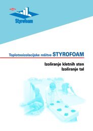
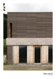
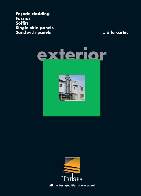
Façade cladding<br />
Fascias<br />
Soffits<br />
Single-skin panels<br />
Sandwich panels ...à la carte.<br />
exterior<br />
All the best qualities in one panel
D1<br />
2<br />
Contents<br />
General information 3<br />
Product data <strong>Trespa</strong> <strong>Meteon</strong> 4<br />
Application and delivery programme 5<br />
Fabrication and installation of <strong>Trespa</strong> <strong>Meteon</strong> Metallics 6<br />
Service and guarantee 6<br />
The technological quality 7<br />
The technical quality 8<br />
Façade applications 9<br />
Ventilated façade cladding 9<br />
Ventilation 10<br />
Fire precautions 10<br />
Joints 11<br />
Corner solutions 12<br />
General guidelines façade cladding 13<br />
Fixing systems 13<br />
General guidelines fixing systems 13<br />
TS150: Visible fixing with screws on a timber subframe 15<br />
TS700: Visible fixing with blind rivets on an aluminium<br />
subframe 19<br />
TS200: Invisible fixing with screws or inserts 25<br />
TS400: Invisible fixing with adhesive and screws 29<br />
TS300: Blind fixing using profiled edges 32<br />
TS650: Blind fixing with clips (Sidings) 33<br />
Panels in frames 35<br />
Single-skin panels in frames 35<br />
Sandwich panels in frames 37<br />
System 700 for overcladding 38<br />
Special fixings 39<br />
Building regulations 40<br />
Standards 40<br />
Auxiliary profiles 40<br />
Fixings 41<br />
Deflection 43<br />
Wind loads and load bearing 44<br />
Addresses 48
General information.<br />
<strong>Trespa</strong> <strong>Meteon</strong> ® is ■ a high-quality building product from <strong>Trespa</strong> International B.V.<br />
■ specifically developed for durable exterior cladding<br />
■ architecturally versatile<br />
■ technically advanced<br />
■ economical<br />
■ environmentally friendly<br />
D1<br />
3
D1<br />
4<br />
Product data <strong>Trespa</strong> <strong>Meteon</strong>.<br />
Material properties <strong>Trespa</strong> <strong>Meteon</strong><br />
Properties Value Unit Standard<br />
Physical properties<br />
Specific gravity ≥ 1.350 kg/m3 ISO 1183<br />
Dimensional stability ≤ 2,5 mm/m EN 438<br />
Resistance to wet conditions<br />
in water of 65°C after 48 hours<br />
EN 438<br />
– Mass increase ≤ 3 %<br />
– Appearance ≥ 4 Rating<br />
Optical properties<br />
Colour stability 4-5 (3000 hrs; Xenon test) Grey Scale ISO 105 A02-93<br />
Mechanical properties<br />
Modulus of elasticity ≥ 9.000 N/mm 2 ISO 178<br />
Tensile strength ≥ 70 N/mm 2 ISO 527-2<br />
Flexural strength ≥ 120 N/mm2 ISO 178<br />
Resistance to impact<br />
by large diameter ball<br />
EN 438<br />
– Drop height 1800 mm<br />
– Diameter of indentation ≤ 6 mm<br />
Scratch resistance ≥ 3 Rating EN 438<br />
Chemical properties<br />
SO2-resistance<br />
Fire behaviour<br />
4-5 (50 cycles;<br />
approx. 0.0067%)<br />
Grey Scale DIN 50018<br />
Great Britain Type FR: Class 0 BS 476 Part 6<br />
Type FR: Class 1 BS 476 Part 7<br />
Fire classification Type Standard: Class 2 BS 476 Part 7<br />
Netherlands Type FR: Klasse 1 NEN 6065<br />
Brandklasse Type Standaard: Klasse 2 NEN 6065<br />
Germany Typ FR: Klasse B1 DIN 4102-1<br />
Baustoffklasse Typ Standard: Klasse B2 DIN 4102-1<br />
France Type FR: Classement M1 NF P 92-501<br />
Réaction au feu Type Standard: Classement M3 NF P 92-501<br />
Indice de fumée Type FR: Classement F1 NF X 10-702 / NF X 70-100<br />
Toxicité des gaz de combustion Type Standard: Classement F1 NF X 10-702 / NF X 70-100<br />
Belgium Type FR: Klasse A1 NBN S21-203<br />
Type Standard: Klasse A2 NBN S21-203<br />
Europe Type FR: Euroclass B-s2, d0 EN13501-1<br />
Type Standard: Euroclass D-s2, d0 EN13501-1<br />
06/2007
Application and delivery programme.<br />
Unique and special <strong>Trespa</strong> <strong>Meteon</strong> is a flat panel, based on thermosetting resins,<br />
homogeneously reinforced with wood fibres and manufactured<br />
under high pressure and at high temperatures, using a<br />
proprietary technology (EBC). The panels have an integrated<br />
decorative surface.<br />
<strong>Trespa</strong> <strong>Meteon</strong> is used for façade cladding, fascias, soffits,<br />
balcony panels and balustrades, urban furniture, sandwich<br />
panels and a wide range of other exterior applications.<br />
<strong>Trespa</strong> <strong>Meteon</strong> is highly suited for ventilated facade systems.<br />
These “breathing” or envelope systems offer possibilities for<br />
high insulation values, perfect building physics and contribute<br />
to a healthy indoor climate.<br />
In Summer, excessive solar heat can be vented away through the<br />
ventilation between the panels and the insulation materials.<br />
<strong>Trespa</strong> <strong>Meteon</strong> is more than just a façade-cladding panel. Over 50<br />
standard colours and the option to choose a decorative surface<br />
on one or both sides make it possible to create any imaginable<br />
modern design. This is complemented by an assortment of<br />
themed decorative surfaces, such as <strong>Meteon</strong> Naturals which<br />
have the colours of natural building materials, <strong>Meteon</strong> Metallics<br />
which have a modern metallic gloss effect, <strong>Meteon</strong> Wood Decors<br />
which have warm wood shades and <strong>Meteon</strong> Originals which<br />
have unique designs. Within this comprehensive range of colours<br />
and textures, you can also choose from various surface textures<br />
in certain product lines with names that speak for themselves:<br />
“Satin” gives a satin gloss, “Gloss” carries a shiny gloss and<br />
“Rock” has a rock texture.<br />
(Different assembly guidelines apply to the Gloss texture).<br />
<strong>Trespa</strong> <strong>Meteon</strong> is available in the standard (non-FR) version<br />
(complies with Euro classification D-s2, d0) and a fire-retardant<br />
(FR) version (complies with Euro classification B-s2, d0). Both<br />
versions have a black core. The fire-retardant version of <strong>Trespa</strong><br />
<strong>Meteon</strong> with a decorative layer on one side is provided with an<br />
identification print on the reverse side of the panel, in addition to<br />
the sticker on the panel. The identification for <strong>Meteon</strong> material<br />
with decorative layers on both sides remains unchanged. The<br />
sticker on the panel enables you to easily distinguish between<br />
standard <strong>Trespa</strong> material (non-FR) and fire-retardant <strong>Trespa</strong><br />
material.<br />
<strong>Trespa</strong> <strong>Meteon</strong> is available in the following sizes:<br />
■ 3650 x 1860 mm<br />
■ 3050 x 1530 mm<br />
■ 2550 x 1860 mm<br />
<strong>Trespa</strong> also offers <strong>Meteon</strong> corner profile elements that meet the<br />
same high standards of <strong>Trespa</strong> <strong>Meteon</strong> flat panels. They are<br />
available with double-sided colour and Satin structure. Standard<br />
corner profile element sizes: 3650 x 300 x 300, radius 20 mm.<br />
Standard corner profile element thicknesses: 8 and 10 mm.<br />
D1<br />
5
D1<br />
6<br />
Fabrication and installation<br />
of <strong>Trespa</strong> <strong>Meteon</strong> Metallics.<br />
Optimizing<br />
Fixing<br />
<strong>Trespa</strong> <strong>Meteon</strong> Metallics<br />
corner profiles<br />
Ordering <strong>Trespa</strong><br />
<strong>Meteon</strong> Metallics<br />
Service and guarantees.<br />
Warranties<br />
<strong>Trespa</strong> <strong>Meteon</strong> Metallics panels feature a directional coloured<br />
surface. In order to achieve te same orientation of the panels<br />
please take notice of the following points:<br />
When optimizing <strong>Trespa</strong> <strong>Meteon</strong> Metallics panels the direction<br />
should always be taken into account. Arrows on the back side<br />
of the fullsize panels have been applied by <strong>Trespa</strong> to indicate the<br />
direction the sheets have been produced (illustration 1)<br />
When cutting the sheets we advise you to temporarily mark the<br />
original production direction on the visible side of the<br />
individual panels. The fixing of the panels in the same direction<br />
wil be easier and this way there will be no undesirable colour<br />
distinction (illustration 2). All other instructions for processing<br />
and fixing are as standard <strong>Trespa</strong> <strong>Meteon</strong> panels.<br />
Corner profile and sheet lenghts have corresponding direction.<br />
The quantity of <strong>Trespa</strong> <strong>Meteon</strong> Metallics sheets required for a<br />
project should be ordered and supplied as a single instruction.<br />
Thanks to practical experience over many years and the high<br />
quality of <strong>Trespa</strong> <strong>Meteon</strong> panels, warranties are available both<br />
for the product range in general and for specific projects. More<br />
information can be obtained from your local <strong>Trespa</strong> office or<br />
representative.<br />
Illustration 1<br />
Illustration 2
The technological quality.<br />
Environmental<br />
considerations<br />
Building<br />
certificates<br />
CE marking<br />
Environmental considerations play a significant role in the<br />
development and manufacture of <strong>Trespa</strong> <strong>Meteon</strong>. Panels consist<br />
of approximately 70% softwood fibre and 30% thermosetting<br />
resin. The wood fibre comes from fast-growing pine wood<br />
from European production forests. Overall some 85% of the<br />
used raw materials are rapidly renewable. In addition up to<br />
10% of residual materials from production are recycled to<br />
produce new <strong>Trespa</strong> construction panels.<br />
<strong>Trespa</strong> International was one of the first producers of panel<br />
material to be certified according to ISO 14001, awarded by<br />
Lloyd’s Register. The ISO 14001 standard describes the steps<br />
required for setting up, implementing, maintaining and improving<br />
a completely integrated environmental management system.<br />
At end of their life cycle <strong>Trespa</strong> <strong>Meteon</strong> panels can be thermally<br />
recycled with energy recovery locally in an industrial incinerator<br />
as they contain no heavy metals, halogens or biocides.<br />
<strong>Trespa</strong> International is able to provide information about the<br />
characteristics of <strong>Trespa</strong> <strong>Meteon</strong>, its safety and effect on the<br />
environment – and has available full product Life Cycle Analyses<br />
(LCAs).<br />
All major European certification institutes which form the<br />
“European Union of Agrément (UEATC)” have certified both<br />
<strong>Trespa</strong> <strong>Meteon</strong> and its recommended fixing systems. Certificates<br />
are issued by amongst others: KOMO; DIBt; BUtgb; BBA;<br />
CSTB and TORROJA.<br />
<strong>Trespa</strong> International has introduced the new CE marking for its<br />
products. <strong>Trespa</strong> <strong>Meteon</strong> fully complies with the requirements<br />
of the new EU standard.<br />
D1<br />
7
D1<br />
8<br />
The technical quality.<br />
Easy to keep clean<br />
Vandalism<br />
Safe fire behaviour<br />
The smooth panel surface has a closed non-porous structure,<br />
ensuring that practically no dirt accumulates. Neither the surface<br />
nor the sawn edges need to be painted or provided with a<br />
protective cover. <strong>Trespa</strong> <strong>Meteon</strong> is completely unaffected by<br />
household cleaning agents or strong organic solvents.<br />
The favourable combination of flexural strength and elasticity<br />
make the panel material highly impact resistant. It is therefore<br />
highly suitable for application in environments that are<br />
exposed to vandalism.<br />
Graffiti can easily be removed without altering the properties<br />
of <strong>Trespa</strong> <strong>Meteon</strong>.<br />
In a fire, <strong>Trespa</strong> <strong>Meteon</strong> does not melt, drip or explode and<br />
retains its stability for a long time.<br />
Key European testing bodies have awarded <strong>Trespa</strong> <strong>Meteon</strong> FR<br />
grade the most favourable classifications for organic material<br />
fire behaviour.
FAÇADE APPLICATIONS.<br />
Ventilated façade cladding.<br />
The load-bearing structure of a building with an exterior<br />
insulation layer can be simply protected from weather<br />
influences by <strong>Trespa</strong> façade cladding.<br />
A ventilated cavity between the façade cladding and the<br />
insulation layer prevents rainwater from penetrating and<br />
diffuses water vapour from the inside to the outside.<br />
The presence of ventilation prevents damp from accumulating<br />
behind the panels. The subframe will not be affected or rot<br />
and the insulation material is prevented from getting wet.<br />
Good ventilation demands that there are openings in the<br />
upper and lower edges of the façade cladding. These are also<br />
necessary at the upper and lower edges of window and door<br />
openings.<br />
Joint profiles usually have an aesthetic function and are able<br />
to limit the amount of moisture that penetrates. However,<br />
these profiles are not essential to guarantee the water tightness<br />
of the façade. Moisture that penetrates is discharged through<br />
the ventilated cavity.<br />
A ventilated façade has the following physical and structural<br />
advantages:<br />
■ No moisture problems in the façade structure as a result of<br />
internal condensation or rain penetration.<br />
■ Movement of the main load-bearing structure is kept to a<br />
minimum by low temperature fluctuations.<br />
■ Local cold bridges are kept to a minimum because the loadbearing<br />
structure is insulated on the outside.<br />
TEMPERATURE DEVELOPMENT IN SUMMER AND WINTER<br />
Rain<br />
Ps<br />
Pw<br />
-10°C<br />
RV = 80%<br />
VENTILATION<br />
Temperature development in summer<br />
Temperature development in winter<br />
MOISTURE LOADS ON FAÇADE STRUCTURE<br />
VENTILATION<br />
Ps = maximum vapour tension<br />
Pw = actual vapour tension<br />
Ps>Pw no internal condensation<br />
+70°C<br />
+60°C<br />
+50°C<br />
+40°C<br />
+30°C<br />
+20°C<br />
+10°C<br />
0°C<br />
- 10°C<br />
+20°C<br />
RV = 60%<br />
Residential<br />
moisture<br />
D1<br />
9
D1<br />
10<br />
Ventilation.<br />
Good ventilation of the <strong>Trespa</strong> façade cladding may be<br />
obtained by following the guidelines listed below:<br />
■ A continuous ventilated cavity of at least 20 mm should be<br />
present behind the façade cladding to prevent damage to the<br />
façade as a result of condensation in the cavity<br />
and/or rain penetration.<br />
■ Ventilation openings may be reduced locally to 5 mm.<br />
■ The upper and lower sides of the façade cladding and<br />
door and window openings should have ventilation<br />
openings that are in direct contact with the outside air.<br />
■ On the one hand the size of the ventilation opening is<br />
determined by the height of the façade cladding, and on the<br />
other hand by local circumstances. Every linear metre<br />
should have at least:<br />
■ 20 square cm/m of ventilation for façade cladding<br />
heights up to 1 metre;<br />
■ 50 square cm/m of ventilation for façade cladding<br />
heights exceeding 1 metre.<br />
■ Ventilation openings that are larger than 10 mm should be<br />
made in such a way that insects and vermin cannot get<br />
behind the façade cladding.<br />
Fire precautions.<br />
Movement of fire within the cavity and/or insulation<br />
materials can possibly take place for multi- storey façades.<br />
Proven systems are developed to prevent this.<br />
These systems are constructed with incombustible insulation<br />
materials and continuous horizontal stainless steel fire<br />
breaks; <strong>Trespa</strong> panels contribute to the required resistance<br />
of fire breaking through.<br />
BETWEEN THE<br />
VERTICAL BATTENS<br />
BETWEEN THE<br />
HORIZONTAL BATTENS
Joints.<br />
The following guidelines apply to joints and panel connections:<br />
■ The panels should be able to move 2.5 mm per metre in the<br />
length and the width. Therefore sufficient space should be<br />
allowed for around the panels.<br />
■ Panel, assembly and building tolerances play an important<br />
role in the joint details. The panels should also be able to<br />
move. Therefore a minimum joint width of 10 mm is required.<br />
■ The joints should be such that sufficient ventilation and/or<br />
drainage is ensured in order to prevent damage as a result of<br />
retained moisture.<br />
■ Insects and vermin may nestle behind the façade cladding.<br />
Joints that are larger than 10 mm should therefore be fixed<br />
with grilles, wire netting, etc.<br />
OPEN JOINTS<br />
The panel connections may either be open or sealed. If an open<br />
joint system is used for vertical and/or horizontal joints, specific<br />
attention should be paid to possible rain or moisture penetration.<br />
When the insulation becomes wet the insulation value decreases<br />
so no longer complies with standards. Moisture resistant<br />
insulation materials and subframes are therefore required.<br />
A vapour open foil can be used as a second water barrier.<br />
CLOSED JOINTS<br />
Tongued-and-grooved and halved joints<br />
With a minimum of 8 mm thick panel it is possible to have<br />
tongue-and-grooved joints on vertical edges or halved joints on<br />
the horizontal edges. This effects a closed joint system. The<br />
minimum dimensions for the joints are:<br />
■ groove: 2.2 x 15 mm for closed aluminium tongues<br />
(panel thickness ≥ 8 mm)<br />
3.2 x 15 mm for <strong>Trespa</strong> tongues<br />
(panel thickness ≥ 10 mm)<br />
■ tongue: 2 x 30 mm for aluminium tongues<br />
3 x 30 mm for <strong>Trespa</strong> tongues<br />
■ height of halved joint: 20 mm<br />
Joint profiles<br />
Joints may be closed by fixing metal, plastic or rubber profiles.<br />
The profiles should not impede the movement of the panels<br />
and should be fixed free of tension.<br />
Mastic joints<br />
Mastic joints impede the movement of the panels and may lead<br />
to excessive dirt on the panel edges. This type of joint sealing is<br />
therefore specifically not recommended.<br />
f<br />
HORIZONTAL JOINTS<br />
Open joint Halved joint Joint profile<br />
a<br />
a 10 mm<br />
f 8 mm<br />
e<br />
≤<br />
≤<br />
a<br />
a<br />
a<br />
VERTICAL JOINTS<br />
Omega profile<br />
Joint gasket<br />
Tongue-and-groove<br />
Open joint<br />
a ≥a 10 mm 10 mm c ≥c 2.9 2,9 mm mm e e ≥ 2 mm 2 mm<br />
b ≥b 15 mm 15 mm d ≥d 2.2 2,2 mm mm f ≥f 8 mm<br />
8 mm<br />
≤<br />
≤<br />
≤<br />
≤<br />
f<br />
a<br />
2<br />
a<br />
2<br />
a<br />
a<br />
a<br />
≤<br />
≤<br />
b<br />
a<br />
2<br />
a<br />
2<br />
a<br />
c<br />
c d<br />
D1<br />
11
D1<br />
12<br />
Corner solutions.<br />
Panel connections at the corners of buildings may have either<br />
open or closed joints. Panels from 8 mm thickness are suitable<br />
for a fixed corner connection where a metal corner profile is<br />
fixed to the back of the panel with screws or inserts. Special<br />
allowances should be made for the differences in length.<br />
If one of the panels is then not able to move in one or more<br />
directions the width of the section in question may not exceed<br />
300 mm. The delivery programme offers a <strong>Trespa</strong> corner profile<br />
element which can be used for a smooth corner detail.<br />
Open corner Corner profile<br />
a<br />
<strong>Trespa</strong> corner<br />
Joint gasket profile element<br />
a<br />
a ≥ 5 mm<br />
a<br />
r<br />
b = 300 mm<br />
3650<br />
r = 20 mm<br />
Fixed corner Corner profile<br />
c<br />
b<br />
Tongue-and groove<br />
c<br />
a a ≥ 5 mm b ≤ 300 mm c ≥ 8 mm<br />
a
General guidelines<br />
façade cladding.<br />
The following aspects should receive attention when a façade<br />
construction consisting of <strong>Trespa</strong> panels, subframes and<br />
fixings are dimensioned:<br />
■ The panels should be suitable for use as self-supporting,<br />
façade cladding.<br />
■ When combined with the subframe the panel strength and<br />
rigidity should be sufficient to withstand normal loads such<br />
as wind, dead weight and/or impact, without being<br />
damaged.<br />
■ The façade cladding should not have a structural function.<br />
■ If heavy objects are to be suspended from the panels,<br />
additional facilities are usually required.<br />
■ The maximum permissible impact loads on the panels and<br />
subframes can be determined by means of specific tests<br />
(usually the sandbag swing test).<br />
■ <strong>Trespa</strong> <strong>Meteon</strong> Metallic panels feature a directional coloured<br />
surface. See page 6 for further information.<br />
FIXING SYSTEMS.<br />
General guidelines<br />
fixing systems.<br />
<strong>Trespa</strong> is assembled with corrosion resistant fixings on a<br />
suitable subframe in such a way that the panels are not under<br />
tension and are able to move freely. When determining the<br />
subframe the following should be kept in mind:<br />
■ wind loading<br />
■ the maximum fixing centres for the panels<br />
■ the required ventilation provisions<br />
■ unimpeded movement of the panels<br />
■ the available panel dimensions<br />
■ thickness of insulation material used, if any<br />
■ the anchoring possibilities in the structural (wall)<br />
construction<br />
■ legal requirements<br />
Fixing<br />
<strong>Trespa</strong> panels may be fixed by the means given below.<br />
Variations and combinations of the methods are optional.<br />
The details in this brochure give the principles of the fixing<br />
systems and do not refer to trade names. Treating of panel<br />
edges is not required as shown in the details.<br />
• fixed visibly with screws<br />
• fixed visibly with rivets<br />
• invisible fixing with screws or (conical) inserts<br />
• invisible fixing with adhesive and screws<br />
• single-skin panel in frame<br />
• sandwich panel in frame<br />
D1<br />
13
D1<br />
14
TS150: Visible fixing with screws on a timber subframe.<br />
Panels with a thickness of 6 mm or more can be fixed onto<br />
a timber subframe. This subframe must consist of battens of<br />
sufficient strength and permanent durability.*<br />
Powdercoated screws or plastic cover caps are available in<br />
all standard <strong>Trespa</strong> colours.<br />
* See chapter ‘Standards’<br />
General<br />
Joints: at least 10 mm<br />
Panel thickness: from 6 mm<br />
Fixing centres and edge clearances<br />
a = horizontal fixing centre (see table)<br />
b = edge clearance<br />
■ minimum 20 mm<br />
■ maximum 10 x panel thickness<br />
c = vertical fixing centre (see table)<br />
maximum fixing centres (in mm)* panel thickness (in mm)<br />
6 8 10 13<br />
2 fixings in one direction 450 600 750 950<br />
3 or more fixings in one direction 550 750 900 1,200<br />
* See also chapters ‘Deflection’ and ‘Wind loads’<br />
Fixing detail<br />
Fast fixing screw for <strong>Trespa</strong> for 6 mm to 10 mm panels.<br />
Diameter of the hole for all fixing points:<br />
■ 8 mm for fast fixing screw for <strong>Trespa</strong><br />
■ shank diameter of the screw + 3 mm for other screws<br />
Timber battens should be at least:<br />
■ 34 x 75 mm for joints between two panels<br />
■ 34 x 45 mm for inner and end battens<br />
Screws should be centered in the holes and not be<br />
overtightened.<br />
b a a b<br />
b<br />
c<br />
c<br />
c<br />
c<br />
b<br />
D1<br />
15
D1<br />
16<br />
TS150: Visible fixing with screws on a timber subframe.<br />
HORIZONTAL CROSS-SECTION<br />
1. <strong>Trespa</strong> <strong>Meteon</strong> corner profile<br />
2. <strong>Trespa</strong> <strong>Meteon</strong> panel<br />
3. Cavity<br />
4. Timber batten<br />
5. <strong>Trespa</strong> 'fast fix' screw<br />
6. Gasket<br />
7. Insulation<br />
8. Coping profile<br />
7<br />
6<br />
4<br />
3<br />
2<br />
1<br />
5<br />
Façade details<br />
Façade<br />
details<br />
8<br />
5<br />
2 3<br />
VERTICAL<br />
CROSS-SECTION<br />
7<br />
Window<br />
details
TS150: Visible fixing with screws on a timber subframe.<br />
VERTICAL CROSS-SECTION<br />
Window<br />
details<br />
1. <strong>Trespa</strong> <strong>Meteon</strong> panel<br />
2. Screw (in the same colour<br />
as the panel)<br />
3. Vertical batten<br />
4. Horizontal batten<br />
5. Cavity<br />
6. Insulation<br />
7. Coping profile<br />
8<br />
8. Sill<br />
9. Ventilation profile<br />
2<br />
7<br />
Façade details<br />
3<br />
1 5 6<br />
9<br />
4<br />
D1<br />
17
D1<br />
18<br />
TS150: Visible fixing with screws on a timber subframe.<br />
VERTICAL CROSS-SECTION<br />
Soffit details<br />
1. <strong>Trespa</strong> <strong>Meteon</strong> panel<br />
2. Screw (in the same colour as the panel)<br />
3. Horizontal batten<br />
4. Gasket<br />
5. Cavity<br />
6. Insulation<br />
1<br />
3<br />
2<br />
4<br />
6<br />
5<br />
3
TS700: Visible fixing with blind rivets on an aluminium<br />
subframe.<br />
Panels that are of minimum 6 mm thickness may be fixed<br />
with rivets. The subframe should preferably consist of vertical<br />
profiles which are fixed to the structure with special wall<br />
brackets.* Horizontal and/or vertical adjusting tolerances are<br />
essential.<br />
* See chapter ‘Standards’<br />
General<br />
Joints: at least 10 mm<br />
Panel thickness: from 6 mm<br />
Fixing centres and edge clearances<br />
a = horizontal fixing centre (see table)<br />
b = edge clearance<br />
■ minimum 20 mm<br />
■ maximimum 10 x panel thickness<br />
c = vertical fixing centre (see table)<br />
x = maximum 3050 mm<br />
y = maximum 3050 mm<br />
a= fixed point in panel centre<br />
s= sliding point<br />
maximum fixing centres (in mm)* panel thickness (in mm)<br />
6 8 10 13<br />
2 fixings in one direction 450 600 750 950<br />
3 or more fixings in one direction 550 750 900 1,200<br />
* See also chapters ‘Deflection’ and ‘Wind loads’.<br />
Fixing detail<br />
Diameter of the hole:<br />
■ fixed point = 5.1 mm<br />
■ sliding points = 10 mm<br />
If the fixed point cannot be placed at the centre of the panel,<br />
2 fixed points may made next to each other. The associated<br />
diameter of the hole should then be 1 mm larger than the rivet<br />
diameter.<br />
A neoprene gasket of 1.5 mm thickness on the subframe can<br />
also be used when the fixed point is not in the centre of the<br />
panel.<br />
The rivet head should be 0.3 mm free from the panel surface<br />
by using a special tool.<br />
b b<br />
a<br />
c<br />
c<br />
c<br />
c<br />
b<br />
b<br />
b b<br />
a<br />
a<br />
Fixing point Sliding point<br />
x<br />
c<br />
c<br />
c<br />
c<br />
b<br />
b<br />
y<br />
D1<br />
19
D1<br />
20
TS700: Visible fixing with blind rivets on an aluminium<br />
subframe.<br />
HORIZONTAL CROSS-SECTION<br />
9<br />
1. <strong>Trespa</strong> <strong>Meteon</strong> panel<br />
2. Aluminium corner profile<br />
3. Aluminium rivet<br />
(with coloured head)<br />
4. Aluminium L-profile<br />
5. Aluminium T-profile<br />
6. Cavity<br />
7. Insulation<br />
4<br />
8<br />
7<br />
5<br />
6<br />
2<br />
1<br />
2<br />
3<br />
Façade details Window details<br />
8. Aluminium rivet<br />
9. Anchor bolt<br />
D1<br />
21
D1<br />
22<br />
TS700: Visible fixing with blind rivets on an aluminium<br />
subframe.<br />
VERTICAL CROSS-SECTION<br />
Window details Façade details<br />
9<br />
1. <strong>Trespa</strong> <strong>Meteon</strong> panel<br />
2. Aluminium rivet<br />
(with coloured head)<br />
3. Aluminium L-profile<br />
4. Fixed point<br />
5. Sliding point<br />
6. Cavity<br />
7. Insulation<br />
3<br />
8. Coping profile<br />
9. Sill<br />
10. Ventilation profile<br />
11. Anchor bolt<br />
8<br />
2<br />
1<br />
6 7<br />
4<br />
5<br />
5<br />
10<br />
11
TS700: Visible fixing with blind rivets on an aluminium<br />
subframe.<br />
VERTICAL CROSS-SECTION<br />
Soffit<br />
details<br />
1<br />
1. <strong>Trespa</strong> <strong>Meteon</strong> panel<br />
2. Aluminium rivet<br />
(with coloured head)<br />
3. Aluminium L-profile<br />
4. Aluminium T-profile<br />
5. Fixed point<br />
6. Sliding point<br />
7. Cavity<br />
2<br />
3<br />
10<br />
9<br />
4<br />
8. Insulation<br />
9. Aluminium rivet<br />
10. Anchor bolt<br />
5 6 5<br />
8<br />
7<br />
5<br />
D1<br />
23
D1<br />
24
TS200: Invisible fixing with<br />
screws or inserts.<br />
Panels of minimum 8 mm thickness may be fixed invisibly by<br />
fixing metal hanging brackets with inserts or screws to the back<br />
of the panel. Invisible fixings for 8 mm panels are possible to a<br />
limited extent. The panels are fixed to metal subframe.<br />
Each panel has two adjusting points and a fixed point at the<br />
top; so adjusting is possible and unwanted movement of the<br />
whole panel can not happen.<br />
General<br />
Joints: at least 10 mm<br />
Panel thickness: from 8 mm<br />
Shortest panel leg of assembled corner panels may not exceed<br />
300 mm if not, a fixed point in the angle is necessary.<br />
Fixing and edge clearances<br />
a = horizontal fixing centre (see table)<br />
b = edge clearance<br />
■ minimum 80 mm<br />
■ maximum 10 x panel thickness<br />
c = vertical fixing centre (see table)<br />
a= fixed point<br />
✕ = adjusting point<br />
s= sliding point:<br />
Lower brackets fixed higher at such a level as to<br />
facilitate downward panel movement (2.5 mm/m 1 )<br />
maximum fixing centres ( in mm)* panel thickness (in mm)<br />
8 10 13<br />
2 fixings in one direction 600 750 950<br />
3 or more fixings in one direction 750 900 1,200<br />
* See also chapters ‘Deflection’ and ‘Wind loads’.<br />
Fixing detail<br />
Fixing method (see also chapter ‘Accessories’)<br />
■ straight insert<br />
■ thread cutting screw<br />
■ conical insert<br />
Remaining panel thickness: at least 2.5 mm.<br />
Anchoring depth: panel thickness - 3 mm.<br />
x x b x x<br />
b b<br />
a<br />
c<br />
c<br />
c<br />
c<br />
b<br />
b b<br />
a<br />
a<br />
c<br />
c<br />
c<br />
c<br />
b<br />
b<br />
D1<br />
25
D1<br />
26<br />
TS200: Invisible fixing with<br />
screws or inserts.<br />
HORIZONTAL CROSS-SECTION<br />
13<br />
14<br />
1. <strong>Trespa</strong> <strong>Meteon</strong> panel<br />
2. Aluminium profile<br />
3. Insert<br />
4. Aluminium rail<br />
5. Adjusting screw<br />
6. Fixed point<br />
7. Aluminium bracket<br />
8. <strong>Trespa</strong> tongue<br />
11 5<br />
7<br />
2<br />
10<br />
9<br />
12<br />
4<br />
6<br />
1<br />
3<br />
8<br />
Façade details Window details<br />
3<br />
9. Aluminium angle<br />
10. Cavity<br />
11. Insulation<br />
12. Aluminium rivet<br />
(with coloured head)<br />
13. Anchor bolt<br />
14. Aluminium wall bracket<br />
5<br />
4
TS200: Invisible fixing with<br />
screws or inserts.<br />
VERTICAL CROSS-SECTION<br />
Window details Façade details<br />
13<br />
1. <strong>Trespa</strong> <strong>Meteon</strong> panel<br />
2. Vertical batten<br />
3. Insert<br />
4. Adjusting screw<br />
5. Aluminium rail<br />
6. Aluminium bracket<br />
7. Aluminium angle<br />
8. Fixed point<br />
3<br />
7<br />
9. Sliding point<br />
10. Cavity<br />
11. Insulation<br />
12. Coping profile<br />
13. Sill<br />
14. Ventilation profile<br />
15. Wood screw<br />
12<br />
8<br />
1 2 11<br />
3<br />
10<br />
4<br />
5<br />
9<br />
14<br />
6<br />
15<br />
D1<br />
27
D1<br />
28<br />
TS200: Invisible fixing with<br />
screws or inserts.<br />
VERTICAL CROSS-SECTION<br />
Soffit<br />
details<br />
1<br />
9<br />
1. <strong>Trespa</strong> <strong>Meteon</strong> panel<br />
2. Vertical batten<br />
3. Insert<br />
4. Adjusting screw<br />
5. Aluminium rail<br />
6. Aluminium bracket<br />
7. <strong>Trespa</strong> tongue<br />
8. Fixed point<br />
7<br />
9. Sliding point<br />
10. Cavity<br />
11. Insulation<br />
12. Wood screw<br />
8<br />
3<br />
11<br />
10 2<br />
4<br />
5<br />
6<br />
12
TS400: Invisible fixing with<br />
adhesive and screws.<br />
The effectiveness of an adhesive fixed panel is determined<br />
mainly by the weather conditions at the time of fixing. Damp,<br />
cold and/or dusty conditions may have a negative effect.<br />
Fixing the <strong>Trespa</strong> panels to wood or metal subframes is<br />
therefore only possible when:<br />
■ for reasons of safety two screws or rivets are fixed to the<br />
top edge of every panel<br />
■ the maximum specified panel dimensions have not been<br />
exceeded so that the panels are able to move freely<br />
■ the bonded joint is made vertically<br />
■ the guidelines specified by the adhesive manufacturers and<br />
advised by <strong>Trespa</strong> are adhered to<br />
General<br />
Joints: minimum 10 mm<br />
Panel thickness: from 6 mm<br />
Panel dimensions: maximum length 2550 mm,<br />
maximum surface 2.5 m 2 .<br />
Fixing and distances from the edge<br />
a = horizontal fixing centre (see table)<br />
d = edge clearance: minimum 20 mm<br />
x = panel width<br />
y = panel height<br />
maximum fixing centres ( in mm)* panel thickness (in mm)<br />
6 8 10<br />
2 fixings in one direction 450 600 650<br />
3 or more fixings in one direction 550 650 650<br />
* See also chapters ‘Deflection’ and ‘Wind loads’.<br />
Fixing detail<br />
Diameter of the hole for the screws:<br />
■ 8 mm for fast fixing screw for <strong>Trespa</strong><br />
■ shank diameter of the screw + 3mm for other screws<br />
Planed timber battens minimum:<br />
■ end battens: 45 x 28 mm<br />
■ intermediate battens: 55 x 28 mm<br />
■ intermediate panel jointing battens: 85 x 28 mm<br />
d<br />
a<br />
x<br />
a<br />
y<br />
D1<br />
29
D1<br />
30
TS400: Invisible fixing with<br />
adhesive and screws.<br />
HORIZONTAL CROSS-SECTION<br />
3<br />
6<br />
5<br />
4<br />
1<br />
1. <strong>Trespa</strong> <strong>Meteon</strong> panel<br />
2. Screw (in the colour of the panel)<br />
3. Vertical batten (planed)<br />
4. Adhesive bead<br />
5. Double-sided adhesive tape<br />
6. Cavity<br />
7. Coping profile<br />
8. Ventilation profile<br />
Façade details<br />
Window details<br />
VERTICAL<br />
CROSS-SECTION<br />
Façade details<br />
7<br />
2<br />
1 3<br />
6<br />
8<br />
D1<br />
31
D1<br />
32<br />
TS300: Blind fixing using<br />
profiled edges<br />
8, 10 and 13mm thick panels can be installed by fitting their<br />
specially grooved horizontal edges into continuous aluminium<br />
TS-300 rails.<br />
The horizontal aluminium TS-300 rails can be fixed to a vertical<br />
timber or aluminium support construction.<br />
The grooved horizontal edges enable the panels to be attached<br />
to the aluminium rails, while hiding the rails from sight.<br />
The TS-300 fixing method is typically suited to install large<br />
uninterrupted façade surfaces with horizontal lines.<br />
General<br />
Joints: 10 mm<br />
Panel thicknesses: 8, 10 and 13mm<br />
Panel size<br />
The TS-300 fixing method can only be used for single-field<br />
spans. As a result, the maximum panel height is limited as<br />
indicated in the table below. The maximum panel width is<br />
1500 mm.<br />
Panel thickness Maximum panel height (in mm)*<br />
8 mm 600 mm<br />
10 mm 750 mm<br />
13 mm 900 mm<br />
* Also see the chapters on ‘Deflection’ and ‘Wind Loads’<br />
TRESPA SYSTEM 300
TS650: Blind fixing with<br />
clips (Sidings)<br />
8mm thick <strong>Trespa</strong> panels have a groove in their bottom edge<br />
enabling them to be attached using special stainless steel fixing<br />
clamps.<br />
The panels are installed from the bottom upwards, with the<br />
first line of clamps being fixed to adjusting blocks or to an<br />
8mm thick adjusting batten (see details). The panels in the top<br />
row are screwed at their top edge.<br />
General<br />
Joints: minimum 10mm<br />
Panel thickness: 8mm<br />
Fixing and edge distances<br />
The panel overlap is approx. 25 mm.<br />
The panel height can vary from 200 to 300 mm; the max. panel<br />
length is 3650 mm. The horizontal clamp fixing distance is max.<br />
600 mm centre-to-centre.<br />
Max. building height 8 m:<br />
Panel thickness Hor. fixing distance Panel height<br />
8 mm 600 mm 200 - 300 mm<br />
Fixing detail<br />
The <strong>Trespa</strong> panels are fixed to vertical timber battens with centre-to-centre<br />
distances of max. 600 mm. The minimum batten<br />
width at the joints must be 75 mm. A width of 50 mm is sufficient<br />
for the other battens.<br />
Every panel is secured in the centre once to prevent it shifting<br />
horizontally.<br />
VERTICAL CROSS-SECTION<br />
1<br />
5<br />
6<br />
4<br />
1. Stainless steel clamp screwed onto timber<br />
2. Thermal insulation<br />
3. Breather foil<br />
4. Ventilated cavity<br />
5. <strong>Trespa</strong> 8 mm<br />
6. Adjustment block thickness 8 mm<br />
7. Ventilation strip<br />
3<br />
7<br />
2<br />
D1<br />
33
D1<br />
34
PANELS IN FRAMES.<br />
Single-skin panels<br />
in frames.<br />
Panels with a thickness from 6 mm can be placed into wood,<br />
metal and plastic frames. Single-skin panels are suitable for<br />
insulated as well as non-insulated walls. Ventilation behind<br />
the panel is always required. Therefore, cavities are made in<br />
the lower and upper horizontal profile. Water drains are also<br />
necessary in the lower horizontal profile. Durable EPDM<br />
gaskets close the gap between profile and panel, mastic and<br />
tape are not allowed for this.<br />
General<br />
Panel thickness: from 6 mm<br />
Panel edge: 6 mm free from the frame at three sides<br />
Fixing centres<br />
x = smallest panel span<br />
y = largest panel span<br />
maximum spans x (in mm)<br />
relation _y<br />
x<br />
panel thickness (in mm)<br />
6 8 10 13<br />
1.0 620 830 1,040 1,350<br />
1.2 580 780 970 1,260<br />
1.4 550 730 910 1,190<br />
1.6 520 690 860 1,130<br />
1.8 490 660 820 1,070<br />
2.0 470 630 780 1,020<br />
≥2.5 450 600 750 980<br />
Fixing detail<br />
Groove in profile: 20 mm deep<br />
EPDM gasket: minimum 4 mm after installation<br />
Water drains / ventilation horizontal profiles:<br />
■ hole diameter 8 mm<br />
■ slotted holes 5 x 25 mm; total 20 cm 2 /m 1<br />
Two supports per panel: minimum 5 x 50 mm<br />
D1<br />
35
D1<br />
36
Sandwich panels<br />
in frames.<br />
<strong>Trespa</strong> sandwich panels are composed of a core of insulating<br />
material and <strong>Trespa</strong> sheets glued on both sides. Panels can be<br />
placed into wood, metal and plastic frames. Sandwich panels are<br />
very suitable for thermal insulation, fire retardant and acoustical<br />
use. Water drains are necessary in the lower horizontal profile<br />
always. Durable EPDM gaskets close the gap between profile<br />
and panel; mastic and tape are not recommended for this.<br />
General<br />
Panel thickness: minimum 16 mm<br />
Panel edge: 6 mm free from the frame at three sides<br />
Composition: 3mm <strong>Trespa</strong> decor; PUR or PS as insulation<br />
Maximum spans on request<br />
Total thickness U-value with PUR-insulation<br />
(mm) (λ = 0.030 W/mK)<br />
16 1.91<br />
21 1.45<br />
26 1.17<br />
31 0.98<br />
36 0.84<br />
46 0.66<br />
56 0.54<br />
66 0.46<br />
Fixing detail<br />
Groove in profile: 20 mm deep<br />
EPDM gasket: minimum 4 mm thickness after installation<br />
Water drains horizontal profiles:<br />
■ hole diameter 8 mm<br />
■ slotted holes 5 x 25 mm<br />
Two supports per panel: minimum 5 x 50 mm<br />
D1<br />
37
D1<br />
38<br />
System 700 for overcladding.<br />
Window pools<br />
Horizontal joint with rebated panels<br />
Fire break
SPECIAL FIXINGS.<br />
Special fixings.<br />
FASCIAS<br />
COMPRIAL<br />
TRESPA SYSTEM 300 (TS 300)<br />
D1<br />
39
D1<br />
40<br />
BUILDING REGULATIONS.<br />
Standards.<br />
The Building Regulations 1991<br />
A1; Loading<br />
A3 & A4; Disproportionate collapse<br />
B1; Means of escape<br />
B4; External fire spread<br />
C4; Resistance to weather and ground moisture<br />
D1; Cavity insulation<br />
E1; Airborne sound (walls)<br />
F1; Means of ventilation<br />
F2; Condensation<br />
L; Conservation of fuel and power<br />
K2; Protection from falling<br />
REG 7; Materials and workmanship<br />
BS 476; Fire tests on building materials and structures.<br />
Part 6. Method of test for fire propagation for products<br />
Part 7. Method for classification of the surface spread of<br />
flame of products<br />
Auxiliary profiles.<br />
Auxiliary profiles are available to close the joints in between<br />
the <strong>Trespa</strong> panels. The most common are pictured below.<br />
The profiles can be supplied by third parties in various colours<br />
and dimensions. The addresses of suppliers will be supplied on<br />
request.<br />
1. Plastic or aluminium corner profile<br />
2. Plastic or aluminium H profile for horizontal joints<br />
(please note that dirt marks are easily made)<br />
3. Plastic or metal ventilation profile<br />
BS 4471; Sizes of sawn and processed softwood<br />
BS 5268; Structural use of timber. Part 5. Code of practice<br />
for the preservative treatment of structural timber<br />
BS 6180; Protective barriers in and about buildings<br />
BS 6206; Impact performance requirements for flat safety<br />
glass and safety plastics for use in buildings<br />
BS 8200; Design of non-loadbearing external vertical<br />
enclosures of buildings<br />
CP3, Chapter V; Part 2: Basic data for the design of buildings.<br />
PD 6484; Commentary on corrosion at bimetallic contact<br />
and its alleviation<br />
1<br />
3<br />
2
Fixings.<br />
Visible fixing<br />
1. Fast fixing screw for <strong>Trespa</strong>, stainless-steel,<br />
for 6 mm to 10 mm panels<br />
• Material: A2 or A4<br />
• Diameter: 4.8 mm<br />
• Length: minimum 36 mm<br />
• Head diameter: 12 mm<br />
• Head height: 2.5 mm<br />
• Hole diameter: 8 mm<br />
• Available in all <strong>Trespa</strong> <strong>Meteon</strong> colours<br />
• For use of other screws keep minimum 4 mm for<br />
diameter and 35 mm for length<br />
2. Aluminium or stainless steel blind rivet for panel<br />
thicknesses from 6 mm<br />
• Material: AlMg5 or A2 or A4<br />
• Diameter: 5 mm<br />
• Head diameter: 14 mm (with cap in <strong>Trespa</strong> <strong>Meteon</strong><br />
colours: 16 mm)<br />
• Head diameter: 16 mm on request (in <strong>Trespa</strong> <strong>Meteon</strong><br />
colours)<br />
• Hole diameter: 10 mm<br />
• Length: panel thickness + subframe + 5 mm minimum<br />
Fast fixing srew for <strong>Trespa</strong><br />
Blind rivet<br />
D1<br />
41
D1<br />
42<br />
Fixings.<br />
Invisible fixing:<br />
1. M6 straight insert for panel thickness of 10 mm and more<br />
• Material:<br />
Insert: brass<br />
Srew: A2 or A4<br />
• Diameter:<br />
Insert: 8.0 mm<br />
Screw: M6<br />
• Length:<br />
Panel thickness 10: 7.5 mm<br />
Panel thickness 13: 10.5 mm<br />
• Hole diameter: 8.0 mm<br />
• Hole depth: special drill with depth stop<br />
2. Thread cutting screw for panel thickness of 8 mm and more<br />
• Typ: EJOT PT S 60xL<br />
• Material: A4<br />
• Diameter: 6.0 mm<br />
• Length:<br />
Panel thickness 8 : 9.5 mm<br />
Panel thickness 10: 11.5 mm<br />
Panel thickness 13: 14.5 mm<br />
(inclusive 5 mm for bracket thickness)<br />
• Hole diameter: 4.9 mm (DF-core)<br />
• Hole diameter: 5.3 mm (kraft-core)<br />
• Hole depth: special drill with depth stop<br />
Panel thickness 8 : 5.5 mm<br />
Panel thickness 10: 7.5 mm<br />
Panel thickness 13: 10.5 mm<br />
3. Stainless-steel conical screw insert<br />
• Typ: Keil Hinterschnittdübel M6<br />
• Material: A4<br />
• Hole depth:<br />
Panel thickness 8 : 5 mm<br />
Panel thickness 10: 7 mm<br />
Panel thickness 13: 10 mm<br />
• Hole diameter: 7 mm/9 mm<br />
to be drilled with a special machine and drill<br />
4. Stainless-steel conical rivet insert<br />
• Typ: Fischer - Zykon - Panelanchor FZP<br />
• Material: A4<br />
• Hole depth:<br />
Panel thickness 8 : 5 mm<br />
Panel thickness 10: 7 mm<br />
Panel thickness 13: 10 mm<br />
• Hole diameter: 9 mm/11 mm<br />
to be drilled with a special machine and drill<br />
Straight insert<br />
Thread cutting screw<br />
Conical screw insert<br />
Conical rivet insert
Deflection.<br />
The maximum flexure (f) limit,<br />
measured at the horizontal<br />
surface of a façade panel<br />
between two fixing points (L),<br />
has been laid down. A minimum<br />
(wind) load should be taken<br />
into account to prevent the<br />
façade structure from not being<br />
strong enough.<br />
Façade cladding flexure:<br />
f ≤ L/200<br />
Wind loads may be multiplied<br />
with 0.70 for calculating panel<br />
deflections, with respect to a<br />
minimum (wind) load of<br />
p ≥ 600 N/m 2 .<br />
Four sided supported<br />
panels:<br />
The graphs can be used for<br />
determining the thickness of<br />
a four sided supported panel.<br />
Determining the thickness, the<br />
shortest panel length (lx) may<br />
be multiplied by correction<br />
factors below after reading the<br />
graph:<br />
Relation correction factor<br />
_l_y for lx<br />
lx<br />
1.0 1.4<br />
1.2 1.3<br />
1.4 1.2<br />
1.6 1.15<br />
1.8 1.10<br />
2.0 1.05<br />
≥ 2.5 1.0<br />
ADMITTED WIND LOAD (N/M 2 )<br />
ADMITTED WIND LOAD (N/M 2 )<br />
2.100<br />
2.000<br />
1.900<br />
1.800<br />
1.700<br />
1.600<br />
1.500<br />
1.400<br />
1.300<br />
1.200<br />
1.100<br />
1.000<br />
900<br />
800<br />
700<br />
600<br />
2.100<br />
2.000<br />
1.900<br />
1.800<br />
1.700<br />
1.600<br />
1.500<br />
1.400<br />
1.300<br />
1.200<br />
1.100<br />
1.000<br />
900<br />
800<br />
700<br />
600<br />
DEFLECTION FOR 2-SUPPORTS (f=L/200)<br />
6 mm 8 mm 10 mm 13 mm<br />
300 400 500 600 700 800 900 1000 1100 1200<br />
350 450 550 650 750 850 950 1050 1150<br />
PANEL SPAN (MM)<br />
DEFLECTION FOR MORE THAN 2-SUPPORTS (f=L/200)<br />
6 mm 8 mm 10 mm<br />
13 mm<br />
300 400 500 600 700 800 900 1000 1100 1200<br />
350 450 550 650 750 850 950 1050 1150<br />
PANEL SPAN (MM)<br />
L<br />
L<br />
L L<br />
D1<br />
43
D1<br />
44<br />
Wind loads and load bearing.<br />
Wind loads:<br />
Pw = c * v 2 / 1.6<br />
p = wind pressure<br />
c = pressure coefficient<br />
v = wind speed<br />
Load bearing:<br />
Load bearing of panels, supports<br />
and fixings included, has to take<br />
place in such a way that maximum<br />
loads do not exceed admitted<br />
strengths.<br />
The weight of a panel will be<br />
spread over several fixings and<br />
can be ignored in the calculation<br />
when a minimum (wind) load of<br />
600 N/m2 is respected.<br />
Visible fixing:<br />
Maximum admittable pull-out<br />
strength for visible fixing with<br />
srews and rivets, depending<br />
on fixing position in panel:<br />
56<br />
54<br />
Londonderry<br />
52 •<br />
50<br />
48<br />
46<br />
Pull-out strength Fixing position in panel<br />
Panel thickness centre edge corner<br />
6 mm 480N 300N 240N<br />
8 mm 500N* 500N* 430N*<br />
10 mm 500N* 500N* 500N*<br />
* maximum pull-out strength for pine wood respectively<br />
aluminium rivet<br />
- including safety factor = 3; for screw, rivet and <strong>Trespa</strong> panel<br />
- safety factor = 4 for pull-out strength in wood<br />
Corner Edge<br />
Centre<br />
46<br />
•<br />
Belfast<br />
50 48<br />
48<br />
60<br />
52<br />
50<br />
Dundee •<br />
• Oban<br />
Perth<br />
•<br />
• Edinburgh 46<br />
• Glasgow<br />
Plymouth<br />
•<br />
Blind fixing:<br />
• Inverness<br />
Aberdeen •<br />
Newcastle•<br />
•Carlisle<br />
Bornemouth•<br />
46<br />
48<br />
56 54<br />
44<br />
48<br />
York<br />
•<br />
•<br />
Preston<br />
• Leeds<br />
Manchester<br />
Kingston/•<br />
• Hull<br />
• Liverpool<br />
• Sheffield<br />
Stoke• Nottingham<br />
•<br />
Birmingham•<br />
Norwich•<br />
• Leicester<br />
• Aberystwyth<br />
Northampton•<br />
Bedford•<br />
Ipswich•<br />
40<br />
Swansea<br />
Cardiff<br />
Oxford<br />
• •<br />
•<br />
•<br />
Bristol<br />
London<br />
38 •<br />
Brighton<br />
•<br />
42<br />
Maximum admittable pull-out strength for blind fixing with<br />
inserts.<br />
panel thickness Pull-out strength<br />
straight thread cutting conical<br />
insert screw insert<br />
8 mm 250N 350N 300N<br />
10 mm 350N 650N 400N<br />
13 mm 550N 1150N 950N<br />
- including safety factor = 3; for insert and <strong>Trespa</strong> panel<br />
- including excentricity factor = 2; for brackets (leverage effect)<br />
41<br />
42
Note<br />
D1<br />
45
D1<br />
46<br />
Note
Note<br />
D1<br />
47
VISIT OUR WEBSITE<br />
WWW.TRESPA.COM<br />
Quality. Design à la carte.<br />
<strong>Trespa</strong><br />
International BV<br />
Four perfect<br />
product lines<br />
Conditions of Sale<br />
Registered<br />
trademarks<br />
<strong>Trespa</strong> International BV specializes in high<br />
quality panel material for façade cladding and<br />
interior use. <strong>Trespa</strong> has both the expertise and<br />
the means to develop products for specific<br />
segments of the market. <strong>Trespa</strong> is continually<br />
looking for ways to protect the environment<br />
even more effectively.<br />
Production of the façade cladding material<br />
<strong>Trespa</strong> <strong>Meteon</strong> is based on unique, patented<br />
techniques, which guarantee excellent weather<br />
resistance and colourfastness. <strong>Trespa</strong> Athlon,<br />
which offers you outstanding moisture<br />
resistance along with scratch and wear<br />
resistance, is particularly suitable for interior<br />
use. <strong>Trespa</strong> Virtuon is aesthetically pleasing<br />
and the perfect product for interior<br />
applications where durability, hygiene,<br />
cleanability are required. And <strong>Trespa</strong><br />
TopLabPLUS , highly resistant to chemicals and<br />
designed for use as laboratory worktops,<br />
completes the product programme.<br />
<strong>Trespa</strong> guarantees quality of both products and<br />
services. We offer our customers optimal<br />
technical support as well as straightforward<br />
documentation. Proof of this approach is the<br />
award of the ISO 9001 and ISO 14001<br />
certificates.<br />
Whatever your requirements, <strong>Trespa</strong> offers a<br />
full support service. Please contact us for<br />
further information.<br />
To all our offers, quotations, sales, deliveries<br />
and supplies and/or agreements, and to all<br />
related services and activities the <strong>Trespa</strong><br />
International B.V. General Conditions of Sale<br />
apply, filed at the Venlo Chamber of<br />
Commerce on 1 January 2004, registered under<br />
number 24270677, and appearing on the<br />
website at www.trespa.com. The text of these<br />
General Terms and Conditions will be sent to<br />
you upon request.<br />
® <strong>Trespa</strong>, <strong>Meteon</strong>, Athlon, Toplab, Virtuon,<br />
Volkern, Ioniq and Inspirations are registered<br />
trademarks of <strong>Trespa</strong> International BV.<br />
<strong>Trespa</strong> UK Ltd<br />
Grosvenor House<br />
Hollinswood Road<br />
Central Park, Telford<br />
TF2 9TW<br />
Tel.: 44 (0) 1952 290707<br />
Fax: 44 (0) 1952 290101<br />
info@trespa.co.uk<br />
<strong>Trespa</strong> International BV<br />
P.O. Box 110, 6000 AC Weert<br />
Wetering 20, 6002 SM Weert<br />
The Netherlands<br />
infoexport@trespa.com<br />
Verkoop Nederland<br />
Tel.: 31 (0) 495 458 850<br />
Fax: 31 (0) 495 540 535<br />
infonederland@trespa.com<br />
EMEA Export<br />
Tel.: 31 (0) 495 458 359 / 285<br />
Fax: 31 (0) 495 458 383<br />
infoexport@trespa.com<br />
Asia/Pacific Sales Support<br />
Tel.: 31 (0) 495 458 538<br />
Fax: 31 (0) 495 458 383<br />
infoapac@trespa.com<br />
<strong>Trespa</strong> Belgium bvba/Sprl<br />
H. van Veldekesingel 150 B. 19<br />
3500 Hasselt<br />
Tel.: 0800 - 15501<br />
Fax: 0800 - 15503<br />
infobelgium@trespa.com<br />
Grand Duché de Luxembourg<br />
Tel.: 31 (0) 495 458 308<br />
<strong>Trespa</strong> Deutschland GmbH<br />
Europaallee 27, D-50226 Frechen<br />
Tel.: 0800 - 186 04 22<br />
Fax: 0800 - 186 07 33<br />
infodeutschland@trespa.com<br />
<strong>Trespa</strong> France<br />
18 rue Chartran<br />
92200 Neuilly sur Seine<br />
Tel.: 33 (0) 1 41 92 04 80<br />
Fax: 33 (0) 1 41 92 04 89<br />
infofrance@trespa.com<br />
GET s.l.<br />
Gran Via, 680 ático<br />
08010 Barcelona<br />
Tel.: (34) 93 488 03 18<br />
Fax: (34) 93 487 32 36<br />
consultatrespa@getsl.com<br />
www.getsl.com<br />
Inpek Srl<br />
Via Val di Vizze 57/e<br />
39040 Prati/Vipiteno (BZ)<br />
Italia<br />
Tel.: +39 0472 76 05 76<br />
Fax: +39 0472 76 35 75<br />
info@inpek.it<br />
www.inpek.it<br />
All the best qualities in one panel<br />
<strong>Trespa</strong> North America Ltd.<br />
12267 Crosthwaite Circle<br />
Poway, CA 92064<br />
Tel.: (1)-800-4-TRESPA<br />
Fax: (1)-858-679-0440<br />
info@trespanorthamerica.com<br />
<strong>Trespa</strong> China Co. Ltd.<br />
Room 2604-05, HuaiHai Plaza<br />
No. 1045 HuaiHai Road (central)<br />
ShangHai 200031, P.R. China<br />
Tel.: 86 (0) 21 6288 1299<br />
Fax: 86 (0) 21 6288 1296<br />
infochina@trespa.com<br />
CSD Asia/Pacific<br />
Tel.: 86 (0) 21 5465 8388<br />
Fax: 86 (0) 21 5465 6989<br />
<strong>Trespa</strong> Singapore Pte Ltd.<br />
UOB Plaza 1<br />
80 Raffles Place<br />
Level 35 Room 8<br />
Singapore 048624<br />
Tel.: 65 6248 4613<br />
Fax: 65 6248 4501<br />
infoapac@trespa.com<br />
Responsibility<br />
All information is based on our current<br />
state of knowledge. It is intended as<br />
information concerning our products and<br />
their application possibilities, and is<br />
therefore not intended as any form of<br />
guarantee with regard to any specific<br />
product characteristic.<br />
Colours<br />
The colours in this document are printed,<br />
and therefore, may vary slightly from the<br />
original <strong>Trespa</strong> panel colours with respect<br />
to gloss, colour shades and surface<br />
texture. Original samples are available on<br />
request.<br />
Copyrights<br />
© All rights reserved. No part of this<br />
publication may be reproduced, stored in<br />
a retrieval system, or made public, in any<br />
form or by any means, either graphic,<br />
electronic or mechanical, including<br />
photocopying, recording or otherwise,<br />
without the prior written permission of<br />
<strong>Trespa</strong> International BV.<br />
www.trespa.com<br />
U001<br />
Zandbeek Communication Group (NL) 1107/2.500