ePowerSwitch 8G Quick Start Guide - LEUNIG GmbH
ePowerSwitch 8G Quick Start Guide - LEUNIG GmbH
ePowerSwitch 8G Quick Start Guide - LEUNIG GmbH

Create successful ePaper yourself
Turn your PDF publications into a flip-book with our unique Google optimized e-Paper software.
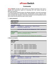
<strong>ePowerSwitch</strong> <strong>8G</strong><br />
Power Management and<br />
Server Monitoring<br />
V.11/2006<br />
<strong>Quick</strong> <strong>Start</strong> <strong>Guide</strong>
© Copyright 2001-2006 by <strong>LEUNIG</strong> <strong>GmbH</strong>, Wilhelm-Ostwald-Straße 17, 53721 Siegburg, Germany<br />
Printed in Germany<br />
All rights reserved. No part of this documentation, accompanying software or other components of the described product<br />
may be reproduced or transmitted in any form or by any means, electronic or mechanical, including photocopying and<br />
recording, for any purpose other than the personal use of the purchaser without the express written permission of Leunig<br />
<strong>GmbH</strong>.<br />
This documentation, the <strong>ePowerSwitch</strong> and its accessories (sensors, I/O extension board, power supply…) and<br />
accompanying software were produced with great care, yet errors are possible.<br />
Leunig <strong>GmbH</strong> assumes no responsibility for errors within the documentation, the hardware or the software.<br />
Leunig <strong>GmbH</strong> reserves the right to change programs or the documentation from time to time without informing the user,<br />
errors and omissions excepted.<br />
Trademarks<br />
All other brand names and product names used in this book are trade names, service marks, trademarks, or<br />
registered trademarks of their respective owners.<br />
WEEE-Reg.-Nr. DE 89822908<br />
<strong>Quick</strong> <strong>Start</strong> <strong>Guide</strong> <strong>ePowerSwitch</strong>-<strong>8G</strong> V.11/2006 Page 2 / 20
<strong>ePowerSwitch</strong> <strong>8G</strong><br />
<strong>Quick</strong> <strong>Start</strong> <strong>Guide</strong><br />
<strong>ePowerSwitch</strong> <strong>8G</strong> is a power control unit with a built-in Web server, an Ethernet port and a<br />
serial RS 232 port. It can be used for switching up to eight power outlets on and off either<br />
remotely through a network (an intranet or the Internet) or locally through a serial connection.<br />
Its special Guard function uses the Ping and Scan functions to allow the <strong>ePowerSwitch</strong> <strong>8G</strong> to<br />
monitor eight separate IP devices (such as servers or routers) and automatically reboot them in<br />
case of a lock-up.<br />
Contents<br />
1. Safety guidelines: Read before use! ........................................................................................4<br />
2. Configuring the <strong>ePowerSwitch</strong> <strong>8G</strong> ...........................................................................................5<br />
2.1 Configuration using the epsFinder program ...........................................................................6<br />
2.2 Configuration using a Web browser .......................................................................................8<br />
2.3 Configuration using a Terminal Connection .........................................................................10<br />
3. Configuring the security settings ............................................................................................12<br />
4. Pinging and Scanning ............................................................................................................14<br />
5. Serial port pin assignment......................................................................................................15<br />
6. Controlling the power outlets through a Web browser............................................................16<br />
7. Controlling the power outlets through a serial connection......................................................17<br />
7.1 Switching the power outlets .................................................................................................17<br />
7.2 Reading out the status of the power outlets .........................................................................18<br />
8. Technical specifications .........................................................................................................19<br />
Konformitätserklärung................................................................................................................20<br />
Declaration of Conformity...........................................................................................................20<br />
<strong>Quick</strong> <strong>Start</strong> <strong>Guide</strong> <strong>ePowerSwitch</strong>-<strong>8G</strong> V.11/2006 Page 3 / 20
1. Safety guidelines: Read before use!<br />
� The <strong>ePowerSwitch</strong> <strong>8G</strong> must be installed and used only by qualified personnel using the<br />
following operating and installation instructions. The manufacturer accepts no responsibility<br />
for damage or injury – either direct or indirect – resulting from improper use of the<br />
<strong>ePowerSwitch</strong> <strong>8G</strong>.<br />
� This equipment is designed for use in a dedicated circuit equipped with a circuit breaker or<br />
fuse protection.<br />
� The electrical mains socket to which the power cables of the <strong>ePowerSwitch</strong> <strong>8G</strong> is connected<br />
must be easily accessible and close to the <strong>ePowerSwitch</strong>.<br />
� Check that the power cords, plugs and sockets are in good condition.<br />
� Connect the <strong>ePowerSwitch</strong> <strong>8G</strong> only to three-wire 230 V AC, 50–60 Hz mains outlets.<br />
� Always plug the <strong>ePowerSwitch</strong> <strong>8G</strong> into properly grounded power outlets (two poles plus<br />
ground).<br />
� The total load for each power input must never exceed 10 amperes.<br />
� This device does not have its own fuse. The electrical installation and/or the connected<br />
consumer must therefore be designed and connected in such a way that the maximum<br />
permissible current of 10 amps for IEC 320 connectors is not exceeded.<br />
� The <strong>ePowerSwitch</strong> <strong>8G</strong> is intended for indoor use only. Do not install it in an area where<br />
excessive moisture or heat is present.<br />
� The power outlets of the <strong>ePowerSwitch</strong> <strong>8G</strong> do not act as circuit breakers! Always disconnect<br />
the mains plug before opening any devices connected to the <strong>ePowerSwitch</strong>.<br />
� The <strong>ePowerSwitch</strong> <strong>8G</strong> contains potentially hazardous voltages. Do not attempt to<br />
disassemble it.<br />
� The <strong>ePowerSwitch</strong> <strong>8G</strong> does not contain any user-serviceable parts. Repairs must be<br />
performed by factory-trained service personnel.<br />
<strong>Quick</strong> <strong>Start</strong> <strong>Guide</strong> <strong>ePowerSwitch</strong>-<strong>8G</strong> V.11/2006 Page 4 / 20
2. Configuring the <strong>ePowerSwitch</strong> <strong>8G</strong><br />
Before you can use the <strong>ePowerSwitch</strong> <strong>8G</strong> in your network, you must configure its network<br />
settings. Ask your network administrator for the correct settings..<br />
You can configure the <strong>ePowerSwitch</strong> <strong>8G</strong> by one of three different methods:<br />
Method 1: Through a network using the epsFinder Program.<br />
This is the simplest and fastest configuration method, but you need access to a PC running the<br />
Windows operating system. You should use this program at least for the first configuration,<br />
because it lets you configure your <strong>ePowerSwitch</strong> through your local network even if its network<br />
settings (IP address, subnet mask and port number) are not the same as those of your PC or<br />
your local network.<br />
This method is described in detail in section 2.1, “Configuration using the epsFinder program”.<br />
The epsFinder Program is included on the supplied CD.<br />
Method 2: Through a network using a Web browser<br />
(Your Web browser must be Internet Explorer 6.0 or higher or Netscape 6.1 or higher.)<br />
This method can be used only if the network settings of the <strong>ePowerSwitch</strong> (IP address, subnet<br />
mask, etc.) have already been configured either using the epsFinder program (method 1) or<br />
using a terminal program (method 3).<br />
During the first configuration, you can also change the network settings of your PC to the default<br />
settings of the <strong>ePowerSwitch</strong>.<br />
Default Network setting of the <strong>ePowerSwitch</strong> are:<br />
IP address: 192.168.100.100<br />
Subnet mask: 255.255.255.0<br />
Gateway: 0.0.0.0<br />
Port number: 80<br />
If you decide to use this method, go to section 2.2, “Configuration using a Web browser”.<br />
Method 3: Through an RS 232 serial connection using a terminal program<br />
(For the pin assignment of the serial connector, see section 5, “Serial port pin assignment”).<br />
If you are using a PC, use the supplied serial cable and a terminal program, such as<br />
HyperTerminal, which is a component of Windows.<br />
If you decide to use this method, go to section 2.3, “Configuration using a terminal connection”.<br />
<strong>Quick</strong> <strong>Start</strong> <strong>Guide</strong> <strong>ePowerSwitch</strong>-<strong>8G</strong> V.11/2006 Page 5 / 20
2.1 Configuration using the epsFinder program<br />
Notes:<br />
∇ The <strong>ePowerSwitch</strong> and the PC used to configure it must be connected to the same network<br />
segment. Because the protocol of the epsFinder program can not be routed, it can not be<br />
used to configure the <strong>ePowerSwitch</strong> through a WAN or the Internet.<br />
∇ The epsFinder program does not work if the administrator has deactivated it in the<br />
<strong>ePowerSwitch</strong> configuration settings (for example for security reasons).<br />
1. <strong>Start</strong> the program epsFinder.exe on the CD-ROM. The <strong>ePowerSwitch</strong> Finder window<br />
appears:<br />
2. On the toolbar, click the first button on the left or select Scan from the File menu. The<br />
program scans the network segment to which your PC is connected and displays the name,<br />
type and IP and MAC addresses of the connected <strong>ePowerSwitch</strong>.<br />
3. on the toolbar, click the second button from the left or select Configure from the File<br />
menu. In the Properties dialog box that appears, enter the required network settings. To set<br />
the remaining parameters, click the Options button at the bottom of the dialog box.<br />
<strong>Quick</strong> <strong>Start</strong> <strong>Guide</strong> <strong>ePowerSwitch</strong>-<strong>8G</strong> V.11/2006 Page 6 / 20
General Tab<br />
On this tab you can make the required network settings (IP address, subnet mask, gateway and<br />
port number) and authorise or deny the configuration of the <strong>ePowerSwitch</strong> <strong>8G</strong> either using the<br />
Finder program or through HTTP.<br />
Labels Tab<br />
On this tab, you can assign a name to the device and its eight controlled power outlets.<br />
Note: Never use inverted commas (") in the name field.<br />
Accounts Tab<br />
On this tab, you can assign a name and a password to the administrator and to up to eight<br />
users. You can also define which outlet(s) each user can control.<br />
Note: Never use inverted commas (") in these fields.<br />
Security Tab<br />
On this tab, enter the IP addresses that are allowed or denied access to the <strong>ePowerSwitch</strong> <strong>8G</strong><br />
over the network. For details about this features, see section 3, “Configuring the security<br />
settings”.<br />
Supervision<br />
On this tab, you can define the IP addresses of the connected devices to be monitored and the<br />
corresponding parameters. The <strong>ePowerSwitch</strong> can monitor IP devices by pinging specific IP<br />
addresses and/or by scanning specific port numbers (see explanation in section 4 “Pinging and<br />
Scanning”).<br />
Note: The guard function works only if the corresponding power outlet is switched On.<br />
Options Tab<br />
On this tab, define individually the default states of each power outlet after power-up and the<br />
delay for the restart function for each power outlet.<br />
Miscellaneous Tab<br />
This tab indicates the firmware version and the number of power-ups and On–Off switching<br />
cycles for each power outlet.<br />
These values can be reset to 0 through a terminal connection using the /RC (Reset Counter)<br />
function (see section 2.3, “Configuration using a Terminal Connection”).<br />
<strong>Quick</strong> <strong>Start</strong> <strong>Guide</strong> <strong>ePowerSwitch</strong>-<strong>8G</strong> V.11/2006 Page 7 / 20
2.2 Configuration using a Web browser<br />
Notes:<br />
∇ Before you can access the Web server of the <strong>ePowerSwitch</strong>, you must define the<br />
<strong>ePowerSwitch</strong>’s network settings. Ask your network administrator for the correct settings).<br />
∇ The Web server of the <strong>ePowerSwitch</strong> works with Internet Explorer version 6.0 or higher and<br />
with Netscape version 6.1 or higher.<br />
1. <strong>Start</strong> your Web browser.<br />
2. Enter the IP address of your <strong>ePowerSwitch</strong>. The browser displays the login dialog.<br />
Enter the administrator name (default: “admin”) and password (default: “admin”) and click<br />
OK. The browser now displays the homepage of the <strong>ePowerSwitch</strong>, where you can define<br />
the settings of the <strong>ePowerSwitch</strong> <strong>8G</strong>.<br />
<strong>Quick</strong> <strong>Start</strong> <strong>Guide</strong> <strong>ePowerSwitch</strong>-<strong>8G</strong> V.11/2006 Page 8 / 20
Home Tab<br />
On this tab, you can switch on, off and restart the controlled power outlets.<br />
General Tab<br />
On this tab, you can:<br />
- assign a label to the <strong>ePowerSwitch</strong> <strong>8G</strong> and its eight controlled power outlets,<br />
- define the IP parameters (IP address, subnet mask, gateway and port number),<br />
- enable or disable the use of the <strong>ePowerSwitch</strong> Finder program,<br />
- enable or disable the configuration of the <strong>ePowerSwitch</strong> using HTTP.<br />
Accounts Tab<br />
On this tab, you can assign a name and password to the administrator and up to eight users<br />
and specify the power outlets each user can control.<br />
Security Tab<br />
On this tab, define your network security masks. For details about this feature, see section 3,<br />
“Configuring the security settings”.<br />
Options Tab<br />
On this tab, define the default states (On, Off or last memorised state) of each power outlet after<br />
power-up and the delay for the restart function for each power outlet.<br />
Misc Tab<br />
This tab displays the number of power-ups and the number of switching cycles from Off to On<br />
for each controlled power outlet.<br />
These values can be reset to 0 through a terminal connection using the /RC (Reset Counter)<br />
function (see section 2.3, “Configuration using a Terminal Connection”).<br />
Supervision 1 to Supervision 8 Tab<br />
On these tabs, enter the IP addresses of the devices to be monitored and the corresponding<br />
settings. The <strong>ePowerSwitch</strong> can monitor IP devices by pinging specific IP addresses and/or by<br />
scanning specific port numbers.<br />
Note: the supervision function works only if the corresponding power outlet is switched On.<br />
To save your settings, click Apply changes.<br />
To cancel the changes, click Discard changes.<br />
To exit without saving the settings, click Exit.<br />
<strong>Quick</strong> <strong>Start</strong> <strong>Guide</strong> <strong>ePowerSwitch</strong>-<strong>8G</strong> V.11/2006 Page 9 / 20
2.3 Configuration using a Terminal Connection<br />
You can also control the <strong>ePowerSwitch</strong>’s power outlets and configure its Web server through its<br />
RS 232 serial port.<br />
To configure the Web server:<br />
1. Using the supplied RS 232 serial cable, connect the <strong>ePowerSwitch</strong> <strong>8G</strong> to a free serial port of<br />
your PC.<br />
2. Run a terminal program such as Windows HyperTerminal or MicroTerminal.<br />
3. Configure the appropriate serial port with the following settings:<br />
Bits per second: 9600<br />
Data bits: 8<br />
Parity: None<br />
Stop bits: 1<br />
Flow control: None<br />
4. On your computer, press until the prompt “>” appears on your screen.<br />
Note: The <strong>ePowerSwitch</strong> is now in Command mode and is waiting for commands to control<br />
the power outlets.<br />
5. Press the key on your keyboard.<br />
The Configuration menu appears on your screen and the <strong>ePowerSwitch</strong> is now in<br />
Configuration mode. Configure the Web server of your <strong>ePowerSwitch</strong> <strong>8G</strong> using the<br />
commands listed on screen.<br />
All commands start with the slash (/).<br />
<strong>Quick</strong> <strong>Start</strong> <strong>Guide</strong> <strong>ePowerSwitch</strong>-<strong>8G</strong> V.11/2006 Page 10 / 20
Examples: To go to the Network Parameters settings menu, type “/NP”<br />
and press .<br />
To display the current menu again, press .<br />
To return to the previous menu, press .<br />
Note: to exit Configuration mode and activate the new configuration, type the restart command<br />
/RS. This is particularly important if you want to control the power outlet later through the serial<br />
connection.<br />
<strong>Quick</strong> <strong>Start</strong> <strong>Guide</strong> <strong>ePowerSwitch</strong>-<strong>8G</strong> V.11/2006 Page 11 / 20
3. Configuring the security settings<br />
Explanation of the mask settings<br />
∇ Each mask consists of an IP address or an IP address range and defines the access rights<br />
to the <strong>ePowerSwitch</strong>’s Web server for those addresses or address ranges.<br />
∇ Each mask can be activated or deactivated.<br />
∇ Each IP address consists of a series of four eight-bit numbers. The number 255 is a wildcard<br />
representing any number.<br />
∇ Masks are listed in order of descending priority; mask 1 has the highest priority.<br />
∇ Higher-priority masks override lower-priority ones.<br />
Example 1<br />
⇒ Deny access to all IP addresses except 192.168.001.015<br />
Example 2<br />
Mask IP address Permit Deny Activated<br />
1 192.168.001.015 � �<br />
2 255.255.255.255 � �<br />
⇒ Permit access only to IP addresses beginning with 192<br />
Example 3<br />
Mask IP address Permit Deny Activated<br />
1 192.255.255.255 � �<br />
2 255.255.255.255 � �<br />
⇒ Permit access only to IP addresses beginning with 192<br />
⇒ Deny access to IP address 192.168.001.010<br />
Mask IP address Permit Deny Activated<br />
1 192.168.001.010 � �<br />
2 192.255.255.255 � �<br />
3 255.255.255.255 � �<br />
<strong>Quick</strong> <strong>Start</strong> <strong>Guide</strong> <strong>ePowerSwitch</strong>-<strong>8G</strong> V.11/2006 Page 12 / 20
Example 4<br />
⇒ Permit access to IP addresses beginning with 192<br />
⇒ Deny access to address 192.168.001.010<br />
⇒ Permit access to IP addresses beginning with 217.128.103<br />
Mask IP address Permit Deny Activated<br />
1 192.168.001.010 � �<br />
2 192.255.255.255 � �<br />
4 217.128.103.255 � �<br />
3 255.255.255.255 � �<br />
<strong>Quick</strong> <strong>Start</strong> <strong>Guide</strong> <strong>ePowerSwitch</strong>-<strong>8G</strong> V.11/2006 Page 13 / 20
4. Pinging and Scanning<br />
The <strong>ePowerSwitch</strong> <strong>8G</strong> uses two methods to check whether IP devices (PCs, servers, routers,<br />
web cams, etc.) are still alive.<br />
Address pinging<br />
The first method uses the well-known Ping command whereby a request is sent to a specific IP<br />
address. The Ping command is an echo request that uses ICMP (Internet Control Message<br />
Protocol) to determine whether an IP device is available on the network. If the system responds<br />
to the request, the <strong>ePowerSwitch</strong> knows that a TCP/IP connection is established. If the system<br />
does not respond to requests, <strong>ePowerSwitch</strong> <strong>8G</strong> can automatically restart the device by cutting<br />
the power to this device and switching it on again after a specified delay.<br />
Port scanning<br />
The second method uses the Port Scan command to test a specific TCP/IP port. This command<br />
allows you to find out if a specific protocol is available on a server (for example HTTP, FTP,<br />
Telnet, SMTP, or POP). The <strong>ePowerSwitch</strong> simply tries a connection to a specific server port. If<br />
the connection is possible, the <strong>ePowerSwitch</strong> knows that a server program is running there. If<br />
the connection is not possible, the <strong>ePowerSwitch</strong> can automatically restart the device by cutting<br />
the power to this device and switching it on again after a specified delay.<br />
Notes:<br />
− The Ping and Scan functions can be used either separately or together.<br />
− The network route between the <strong>ePowerSwitch</strong> <strong>8G</strong> and the monitored IP device should be as<br />
direct as possible: avoid unnecessary routers and complex wiring. A router or wiring fault<br />
could cause an accidental reboot of the monitored IP device.<br />
− Execute several Pings and/or Scans before running the Reboot function. It could be possible<br />
that the monitored IP device does not respond even though it is operational.<br />
− Choose a realistic monitoring cycle. An interval of one second is possible, but this may<br />
overload the network with Ping and Scan requests.<br />
Recommended values:<br />
Interval between requests: at least 10 seconds<br />
Number of unsuccessful requests before reboot: at least 3<br />
Delay before reboot: at least 10 seconds<br />
Delay before first request after reboot: at least 120 seconds<br />
<strong>Quick</strong> <strong>Start</strong> <strong>Guide</strong> <strong>ePowerSwitch</strong>-<strong>8G</strong> V.11/2006 Page 14 / 20
5. Serial port pin assignment<br />
The 9-pin Sub-D connector for the serial connection has the following pin assignment:<br />
Pin 2: TxD (transmit data to the PC)<br />
Pin 3: RxD (receive commands)<br />
Pin 5: GnD (ground)<br />
The port settings are:<br />
Bits per second: 9600<br />
Data bits: 8<br />
Parity: None<br />
Stop bits: 1<br />
Flow control: None<br />
<strong>Quick</strong> <strong>Start</strong> <strong>Guide</strong> <strong>ePowerSwitch</strong>-<strong>8G</strong> V.11/2006 Page 15 / 20
6. Controlling the power outlets through a Web browser<br />
1. <strong>Start</strong> your Web browser.<br />
Enter the IP address of your <strong>ePowerSwitch</strong>.<br />
The browser displays the login dialog box.<br />
2. Enter a user name and its corresponding password.<br />
− If you log on as administrator (default name: “admin”, default password: “admin”), you can<br />
control all power sockets and change all <strong>ePowerSwitch</strong> settings.<br />
− If you log on as a user (default names: “user1”, “user2”, “user3”, ... “user8”; corresponding<br />
default passwords: “user1”, “user2”, “user3”, ... “user8”), you can control only the sockets to<br />
which this user has authorized access.<br />
Use the ON and OFF button to switch the socket On and Off.<br />
Use the Restart button switches the socket Off. It is automatically switched on again after a<br />
delay specified by the administrator (default value: 5 seconds).<br />
The IP monitoring status is shown below the command button.<br />
− If monitoring is deactivated, the message “Supervision deactivated” is displayed.<br />
− If monitoring is active, the message “Supervision activated” is displayed.<br />
This setting can be changed only by the administrator.<br />
Note: If you switch the socket Off, monitoring is temporarily deactivated and the message<br />
“Supervision temporarily deactivated” is displayed.<br />
<strong>Quick</strong> <strong>Start</strong> <strong>Guide</strong> <strong>ePowerSwitch</strong>-<strong>8G</strong> V.11/2006 Page 16 / 20
7. Controlling the power outlets through a serial connection<br />
The power outlets of the <strong>ePowerSwitch</strong> <strong>8G</strong> can also be controlled through an RS 232 serial<br />
connection using a simple ASCII protocol.<br />
To control the power outlets:<br />
1. With the supplied RS 232 serial cable, connect the <strong>ePowerSwitch</strong> <strong>8G</strong> to an available serial<br />
port of your PC.<br />
2. Run a terminal program such as Windows HyperTerminal or MicroTerminal.<br />
3. Configure the appropriate serial port with the following settings:<br />
Bits per second: 9600<br />
Data bits: 8<br />
Parity: None<br />
Stop bits: 1<br />
Flow control: None<br />
4. On your computer, press until the prompt (>) appears on your screen.<br />
The <strong>ePowerSwitch</strong> <strong>8G</strong> is now in command mode and is waiting for user input to switch the<br />
power outlets.<br />
Note: The power outlets of the <strong>ePowerSwitch</strong> can be controlled only if the <strong>ePowerSwitch</strong> is in<br />
Command mode and not in Configuration mode. To exit Configuration mode and activate the<br />
new configuration, enter /RS. By default, the <strong>ePowerSwitch</strong> is in Command mode after a powerup.<br />
7.1 Switching the power outlets<br />
The command syntax is Px=y<br />
Where x = power outlet number (0 to 8):<br />
0: all power outlets together<br />
1: power outlet 1<br />
2: power outlet 2<br />
3: power outlet 3<br />
4: power outlet 4<br />
5: power outlet 5<br />
6: power outlet 6<br />
7: power outlet 7<br />
8: power outlet 8<br />
and y defines the action to be performed:<br />
0: switch power outlet(s) Off<br />
1: switch power outlet(s) On<br />
r: restart power outlet(s)<br />
t: toggle power outlet(s)<br />
<strong>Quick</strong> <strong>Start</strong> <strong>Guide</strong> <strong>ePowerSwitch</strong>-<strong>8G</strong> V.11/2006 Page 17 / 20
Examples:<br />
Switch power outlet 1 On: p1=1<br />
Switch power outlet 2 Off: p2=0<br />
Restart power outlet 1: p1=r<br />
Restart power outlet 4: p4=r<br />
Toggle power outlet 3: p3=t<br />
Switch all power outlets On: p0=1<br />
Restart all power outlets: p0=r<br />
The commands are not case-sensitive, i.e. you can use upper- and lower-case letters.<br />
To display the firmware version, type “?” followed by .<br />
7.2 Reading out the status of the power outlets<br />
In the same way, the status of the power outlets can be read out using the following syntax:<br />
Rx <br />
The <strong>ePowerSwitch</strong> then sends the status with the following syntax:<br />
Px=y">"<br />
y = 0 if the power outlet is Off<br />
y = 1 if the power outlet is On<br />
= Carriage Return<br />
= Line Feed<br />
">" = ">" character as prompt<br />
Examples:<br />
Read out the status of power outlet 1:<br />
R1 <br />
Read out the status of power outlet 2:<br />
R2 <br />
<strong>Quick</strong> <strong>Start</strong> <strong>Guide</strong> <strong>ePowerSwitch</strong>-<strong>8G</strong> V.11/2006 Page 18 / 20
8. Technical specifications<br />
Network standards IEEE 802.3, 10Base-T<br />
Network protocols TCP/IP, HTTP<br />
Network connection RJ-45 connector for UTP CAT5<br />
Max. network cable length 100 meters (not included)<br />
Serial connection RS232, SUB-D 9-pin female<br />
Nominal input voltage 230 V/50 Hz<br />
Input power socket IEC-320<br />
Output voltage 230 V/50 Hz<br />
Output power sockets IEC-320<br />
Maximum total current 2 x 10 A<br />
LEDs 1 for Power and Network Traffic (PL)<br />
1 for Power Supply Group A (outlet 1 to 4) (PA)<br />
1 for Power Supply Group B (outlet 5 to 8) (PB)<br />
1 for Supervision Activity in progress for group A (SA)<br />
1 for Supervision Activity in progress for group B (SB)<br />
8 for power outlet status<br />
Operating temperature 0 °C to +40 °C<br />
Operating humidity 10 % to 80 %<br />
Dimensions 437 x 107 x 42 mm<br />
Weight 2 kg<br />
Approvals CE, EN 55022 & EN 55024<br />
Warranty 2 years repair or replace<br />
<strong>Quick</strong> <strong>Start</strong> <strong>Guide</strong> <strong>ePowerSwitch</strong>-<strong>8G</strong> V.11/2006 Page 19 / 20
Konformitätserklärung<br />
Für unser Erzeugnis ”<strong>ePowerSwitch</strong>” in den Varianten <strong>ePowerSwitch</strong>-4, <strong>ePowerSwitch</strong> 1G, <strong>ePowerSwitch</strong> 4G,<br />
<strong>ePowerSwitch</strong> <strong>8G</strong>, <strong>ePowerSwitch</strong> M8, <strong>ePowerSwitch</strong> S8, <strong>ePowerSwitch</strong> 4XM, <strong>ePowerSwitch</strong> 8XM, <strong>ePowerSwitch</strong> 8XS<br />
wird hiermit bestätigt, dass es den wesentlichen Schutzanforderungen entspricht, die in den Richtlinien des Rates über<br />
elektrische und elektronische Produkte festgelegt sind:<br />
1. 89/336/EWG EMV-Richtlinie<br />
2. 73/23, bzw. 93/68 Niederspannungsrichtlinie<br />
Zur Beurteilung wurden folgende Normen herangezogen:<br />
Zu 1. Elektromagnetische Verträglichkeit nach<br />
EN55022 Klasse B (1998) + A1, A2<br />
EN55024 (1998) + A1, A2<br />
EN61000-3-2 (2000) +A2<br />
EN61000-3-3 (1995) + A1<br />
Zu 2. Elektrische Sicherheit nach<br />
EN60950-1 (2001)<br />
Diese Erklärung wird verantwortlich für den Hersteller abgegeben durch (siehe unten):<br />
Declaration of Conformity<br />
We hereby declare that the versions <strong>ePowerSwitch</strong>-4, <strong>ePowerSwitch</strong> 1G, <strong>ePowerSwitch</strong> 4G, <strong>ePowerSwitch</strong> <strong>8G</strong>,<br />
<strong>ePowerSwitch</strong> M8, <strong>ePowerSwitch</strong> S8, <strong>ePowerSwitch</strong> 4XM, <strong>ePowerSwitch</strong> 8XM, <strong>ePowerSwitch</strong> 8XS of our <strong>ePowerSwitch</strong><br />
product meet the safety requirements specified in the European Union directives relating to electrical and electronic products:<br />
1. EMC Directive 89/336/EEC<br />
2. Low Voltage Directive 73/23/EEC and 93/68/EEC<br />
The following standards were used in assessing conformity:<br />
Electromagnetic compatibility<br />
EN 55022 Class B (1998) + A1, A2<br />
EN 55024 (1998) + A1, A2<br />
EN 61000-3-2 (2000) +A2<br />
EN 61000-3-3 (1995) + A1<br />
Electrical safety<br />
EN 60950-1 (2001)<br />
This Declaration is issued by:<br />
<strong>LEUNIG</strong> GMBH<br />
D-53721 Siegburg<br />
Siegburg, 14.12.2006<br />
Peter H. Leunig<br />
General Manager<br />
All modifications reserved<br />
EPS-<strong>8G</strong>_2006_11_EN<br />
15/12/2006<br />
<strong>Quick</strong> <strong>Start</strong> <strong>Guide</strong> <strong>ePowerSwitch</strong>-<strong>8G</strong> V.11/2006 Page 20 / 20