

INCUBADORA SANYO MCO-17AC SERVICE MANUAL

You also want an ePaper? Increase the reach of your titles
YUMPU automatically turns print PDFs into web optimized ePapers that Google loves.
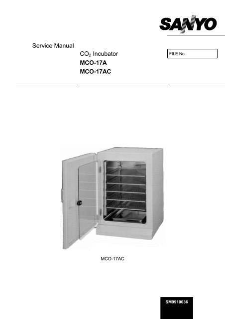
Service Manual<br />
CO 2 Incubator<br />
<strong>MCO</strong>-17A<br />
<strong>MCO</strong>-<strong>17AC</strong><br />
FILE No.<br />
<strong>MCO</strong>-<strong>17AC</strong><br />
<br />
SM9910036
Effective models<br />
This service manual is effective following models.<br />
Model name Product code Voltage and Frequency<br />
<strong>MCO</strong>-17A 823 247 51 110-120V 60Hz<br />
823 247 52 220-240V 50/60Hz<br />
823 247 53 220-240V 50/60Hz<br />
823 247 54 110-120V 60Hz<br />
823 247 55 240V 50Hz<br />
823 247 56 220V 50Hz<br />
823 247 57 220-240V 50/60Hz<br />
823 247 58 110-120V 50/60Hz<br />
823 247 59 220V 50/60Hz<br />
823 247 60 220-240V 50/60Hz<br />
823 247 61 220-240V 50/60Hz<br />
<strong>MCO</strong>-<strong>17AC</strong> 823 272 51 110-120V 60Hz<br />
823 272 53 220-240V 50/60Hz<br />
823 272 54 220-240V 50Hz<br />
823 272 56 110-120V 60Hz<br />
823 272 57 110-120V 60Hz
Features<br />
1. PID temperature controls with micro-computer.<br />
This unit has PID control (Proportional Integrate Differential) accurate controls internal<br />
temperature, as well as air sensor system monitoring internal temperature.<br />
2. Easy install.<br />
This unit use air jacket type chamber which is no need to feed water. It is possible easy to<br />
install and easy to maintenance.<br />
3. Warning system.<br />
This model has temperature (include over heating protection) and CO 2 density alarm<br />
system.<br />
4. CFC-FREE insulation.<br />
Insulation system of model <strong>MCO</strong>-<strong>17AC</strong> uses CFC-FREE type rigid polyurethane foam in<br />
place and glass wool.<br />
5. Rounded Ball corners.<br />
Inside chamber wall made by stainless steel and its corner made rounded type.<br />
This made cleaning easier and de-contamination.<br />
Note; Model name<br />
M CO – 17 A C<br />
Copper alloyed stainless steel<br />
Air jacket type<br />
Chamber capacity 164L<br />
CO 2 Incubator<br />
Medical equipment<br />
NOTICE<br />
In general, stainless steel is known that it is not easy (hard) to rust.<br />
However, depends on conditions, rust might generate.<br />
When you remove rust, we recommend the following agents.<br />
Besides, the surface may become foggy.<br />
Recommended agent:<br />
1.Cream creanser “Gif” (Unilever)<br />
2.Picasso #SUS300-W (Chemical YAMAMOTO)<br />
* Picasso has greater capability of clean for rust than “Gif”.<br />
1
Specifications<br />
<br />
Name<br />
CO 2 incubator<br />
Model <strong>MCO</strong>-17A <strong>MCO</strong>-<strong>17AC</strong><br />
External dimensions<br />
W620 x D605 x H900 (mm)<br />
Internal dimensions<br />
Interior volume<br />
W490 x D505 x H665 (mm)<br />
164 L<br />
Tray<br />
Stainless steel containing copper<br />
5 (standard), 17 (maximum)<br />
Exterior<br />
Acrylic finish baked on galvanized steel<br />
Interior Stainless steel (SUS-304) Stainless steel containing copper<br />
Outer door<br />
Inner door<br />
Insulation<br />
Heating system<br />
Humidifying system<br />
Temperature controller<br />
CO 2 controller<br />
Air circulation<br />
Acrylic finish baked on galvanized steel<br />
Tempered glass<br />
Rigid polyurethane foam in place (CFC-FREE)<br />
DHA (heater jacket + air jacket system)<br />
Natural evaporation with humidifying pan<br />
PID control<br />
ON-OFF control system<br />
Stir up of breeze<br />
Air filter 0.3m, Efficiency 99.97%<br />
Alarm<br />
Capacity of contact point<br />
for remote alarm<br />
Output of recorder<br />
terminal<br />
CO 2 connecting inlet<br />
Weight<br />
Accessories<br />
Optional component<br />
Temperature alarm, CO 2 density alarm, upper limit temperature alarm,<br />
door alarm<br />
AC125V, 0.4A; DC30V, 2A<br />
0~100mV (temperature, CO 2 density)<br />
4~6 mm tube<br />
84kg<br />
5trays, 5sets of tray support, 1gas tube, 1humidifying pan<br />
CO 2 pressure regulator (<strong>MCO</strong>-100L), stainless tray (<strong>MCO</strong>-46ST),<br />
Stack kit (<strong>MCO</strong>-18PS)<br />
<br />
Usable environment condition<br />
0~+35<br />
Temperature control range<br />
Ambient temperature +5~+50<br />
Temperature variation<br />
0.1<br />
Temperature distribution<br />
0.2*<br />
CO 2 control range 0~20.0%<br />
CO 2 variation<br />
0.15%*<br />
Chamber humidity<br />
955%R.H.<br />
CO 2 secondary pressure 0.03MpaG (0.3kg/cm 2 G)<br />
Maximum power consumption<br />
380W<br />
Noise level<br />
33dB (A scale)<br />
* Value measured at 37, CO 2 density of 5.0%, ambient temperature 20. It is based on<br />
<strong>SANYO</strong> measuring method.<br />
2
Dimensions<br />
3
Electrical Parts<br />
<strong>MCO</strong>-17A,<strong>17AC</strong><br />
AC110120V, 50/60Hz<br />
AC220240V, 50/60Hz<br />
Power transformer Type ATR-HN231UT ATR-HN235T<br />
Rating 115V 8.5/18.0V 230V 8.5/18.0V<br />
Bottom heater Type 14.0W (4pcs) 14.0W (4pcs)<br />
Rating 945 115V 377 115V<br />
Side heater R Type 22.0W (2pcs) 22.0W (2pcs)<br />
Rating 601 115V 2404 230V<br />
Side heater L Type 22.0W (2pcs) 22.0W (2pcs)<br />
Rating 601 115V 2404 230V<br />
Flange heater Type 45.0W 45.0W<br />
Rating 294 115V 1176 230V<br />
Back heater Type 23.0W 23.0W<br />
Rating 586 115V 2344 230V<br />
Front heater Type 35.0W 23.0W<br />
Rating 378 115V 1511 230V<br />
Door heater Type 120.0W 120.0W<br />
Rating 110 115V 441 230V<br />
Door heater (sub2) Type 17.0W 14.0W<br />
Rating 945 115V 3779 230V<br />
Door heater (sub3) Type 17.0W 14.0W<br />
Rating 945 115V 3779 230V<br />
Fan motor Type FL2-011Y1M FL2-011Y5M<br />
Rating 1 110V 50/60Hz 1 230V 50/60Hz<br />
Power switch Type AJ921000B AJ921000B<br />
Rating AC250V 16A AC250V 16A<br />
Noise filter Type ZCE2203-11 ZCE2203-11<br />
Rating AC250V 3A 50/60Hz AC250V 3A 50/60Hz<br />
Solenoid valve Type FAB11-X1528 FAB11-X1528<br />
Rating Coil: DC24V 1.8W Coil: DC24V 1.8W<br />
Temperature control sensor Type 103-AT1 103-AT1<br />
(Thermistor sensor) Rating 10k 10k<br />
Overheat protect sensor Type 103-AT1 103-AT1<br />
(Thermistor sensor) Rating 10k 10k<br />
AT sensor Type 103-AT1 103-AT1<br />
(Thermistor sensor) Rating 10k 10k<br />
P.C.B.<br />
Type CO-17AI CO-17AI<br />
Door switch<br />
Type SS160-A15 SS160-A15<br />
CO 2 sensor Type HS-3C-S2 HS-3C-S2<br />
Rating 100% 100mV 100% 100mV<br />
4
Control specifications<br />
1. Key and switch<br />
BUZZER: When number is flashing and the buzzer does not sound,<br />
Buzzer and remote alarm output<br />
Forced ON<br />
When number is flashing and the buzzer sounds,<br />
Buzzer and remote alarm output<br />
Forced OFF<br />
SET : The first time you press SET the apparatus goes into temperature setting mode.<br />
The second time into CO 2 density setting mode, the third time into excessive<br />
temperature rise prevention/checking mode, and the forth time it reverts to internal<br />
temperature display mode.<br />
: When you press this key in setting mode the highlighted number changes from/to<br />
the tens place, one place and the tenths place. Also, holding this key down for<br />
about 5 seconds in internal temperature display mode activates key lock mode.<br />
: Press this key in setting mode to increase the flashing number.<br />
CAL : Hold this key down for about 5 seconds in internal temperature display mode to<br />
switch into temperature calibration mode. Press it once again to switch to CO 2<br />
calibration mode. Also keying in FXX in temperature calibration mode switches to<br />
function mode.<br />
ENT : Press this key in setting mode, CAL mode and Function mode to memorize the<br />
number.<br />
2. Temperature control<br />
Setting range : 050<br />
Setting method : Press SET key once, and set temperature using key and key.<br />
When you press ENT key, the temperature setting is memorized and the<br />
apparatus goes into CO 2 setting mode.<br />
Outside permitted<br />
range:<br />
If you key in a temperature outside the setting range and press ENT, the<br />
buzzer sounds (for about 1second continuously) and it stays in<br />
temperature setting mode.<br />
Control : PID control<br />
Alarm : If the internal temperature is 1 higher/lower than setting, the number<br />
flashes and after a delay of 15minutes the buzzer comes on.<br />
3. CO 2 control<br />
Setting range : 0%~20%<br />
Setting method : Press SET key twice to set CO 2 density with key and key.<br />
When you press ENT key to memorize the CO 2 setting and the apparatus<br />
goes into excessive temperature rise prevention/checking mode.<br />
Out of permitted<br />
range:<br />
If you key in a figure outside the setting range and press ENT, the buzzer<br />
sounds (for about 1second continuously) and it stays in CO 2 setting mode.<br />
5
Control : ON-OFF type<br />
(Valve is closed if the CO 2 density is setting –0.02% or higher, opens if it is<br />
setting –0.06% or lower)<br />
Control OFF : If you set it at 0.0%, the CO 2 density display vanishes and control is OFF.<br />
Alarm : If the CO 2 density is 1% higher/lower than the setting, the number flashes<br />
and after a delay of 15minutes the buzzer and remote output come on.<br />
4. Excessive temperature rise prevention / checking<br />
Setting range : +35+51<br />
Setting method : Press SET key 3times to display excessive temperature rise prevention<br />
setting in temperature display and “HI” in CO 2 display. This setting value<br />
can be changed by tuning the volume.<br />
When you press SET key again to revert the apparatus to internal<br />
temperature display mode.<br />
5. Self-diagnostic function<br />
In sensors are malfunctions or CO 2 cylinder is detected empty, an error code and the<br />
temperature are displayed alternately. Also the buzzer and remote alarm output come on.<br />
<br />
E01: CO 2 cylinder empty<br />
E02: Internal temperature sensor wiring open-circuiting or short-circuiting<br />
E03: CO 2 sensor output abnormality<br />
E04: Ambient temperature sensor wiring open-circuiting or short-circuiting<br />
Note) If 2 errors occur (2error codes are generated) simultaneously, only the code<br />
for the one with the bigger number is displayed.<br />
6. Lock function<br />
Key lock mode :<br />
Note)<br />
To switch to lock mode, hold the key (shift key) down for about 5<br />
seconds when the current internal temperature is being displayed.<br />
When lock mode is activated “L0” is displayed in the temperature display<br />
Press<br />
key to change the key lock status:<br />
L1 ……… Key lock ON<br />
L0 ……… Key lock OFF<br />
Press ENT to memorize the current condition and revert to internal<br />
display mode.<br />
7. Door alarm<br />
Display<br />
Safety operation :<br />
: When the door is open ……… DOOR lamp ON<br />
When the door is closed …….. DOOR lamp OFF<br />
When the door is open, the fan motor is turned off, the CO 2 valve is<br />
closed, and if it stays open for more than 60seconds the heater is also<br />
turned off.<br />
6
8. Auto return function<br />
If no keys are pressed for 90 seconds in setting mode, lock mode or<br />
function mode, the apparatus automatically exits these modes.<br />
9. Calibration function<br />
Temperature : Hold the CAL key down for about 5 seconds in internal temperature<br />
display mode to switch into temperature calibration mode.<br />
When you input the correct temperature using the and keys and<br />
press ENT key, the temperature is memorized and the incubator reverts<br />
to internal temperature display mode.<br />
CO 2 : To activate CO 2 calibration mode, hold the CAL key down for about<br />
5seconds in internal temperature display mode to switch to temperature<br />
calibration mode, and then press the CAL key once more.<br />
If you then key in 00.0 using the and key and press ENT key,<br />
the apparatus memorizes the current internal concentration detected,<br />
calls it 0.0%, and it reverts to internal temperature display mode.<br />
Alternatively, if you key in correct concentration when CO 2 control is<br />
operational and press ENT, it memorizes this as the span calibration<br />
value and reverts to internal temperature display mode.<br />
10. Function mode<br />
Function mode incorporates the following functions:<br />
F00: A ROM version display<br />
F01: Demo (demonstration) mode setting<br />
F02: Humidity heater degree of energizing set<br />
F03: Temperature analogue output calibration<br />
F04: CO 2 analogue output calibration<br />
F05: CO 2 sensor output voltage (A/D input) display<br />
F06: Ambient temperature display<br />
F09: Memory initialization<br />
Direction for use: In internal temperature display mode, hold the CAL key down for about<br />
5seconds to switch to temperature calibration mode. Key in desired<br />
function code in temperature display section and press ENT key.<br />
F00: Displays a ROM version in the CO 2 display.<br />
F01: Sets demo mode.<br />
Key in X1X in the CO 2 display and press ENT to go into demo mode.<br />
In demo mode, the settings are displayed continuously, and energizing of the<br />
heater/valve stops. Also, all alarms are cancelled.<br />
To exit demo mode, key in X0X and press ENT.<br />
(X= any number)<br />
F02: Sets degree of energizing for humidity heater’s main heater<br />
Key in a number between 0 and 9 after the decimal point in the CO 2 display and<br />
press ENT key. The bigger the number you key in, the greater the degree of<br />
energizing, the higher the internal humidity.<br />
F03: Calibrates the temperature analogue output<br />
Key in a number twice of actual temperature analogue output voltage in the CO 2<br />
display and press ENT key.<br />
7
F04: Calibrates the CO 2 analogue output<br />
Key in a number of actual CO 2 analogue output voltage in the CO 2 display and<br />
press ENT key.<br />
F05: Displays the CO 2 sensor input voltage (A/D input)<br />
Displays the CO 2 sensor input voltage in the display. Unit = <br />
F06: Displays ambient temperature<br />
Indicates the present temperature sensor.<br />
F09: Initializes the CO 2 calibration value and the non-volatile memory<br />
Key in XX5 in the CO 2 display and press ENT key to initialize the CO 2 zero<br />
adjustment value and the span adjustment value.<br />
Key in XX9 in the CO 2 display and press ENT key to initialize all the data in the<br />
non-volatile memory.<br />
The initial values in the non-volatile memory are as follows:<br />
Temperature setting 37.0<br />
CO 2 setting 0.0%<br />
Humidity heater balance 4<br />
Temperature Zero Adjustment data 0.0<br />
CO 2 Zero adjustment data 0.0<br />
CO 2 span data 1.0<br />
Temperature analogue calibration value 220<br />
CO 2 Analogue calibration value 110<br />
Key lock data<br />
Key lock OFF<br />
Demo data<br />
Demo OFF<br />
This function is used when non-volatile data has been destroyed as a result, for<br />
example, of unavoidable noise, and cannot be repaired/recovered. Hence, it is<br />
not used in normal circumstances.<br />
11. Humidifying heater control<br />
The humidifying heater is energized, as described below, in order to reduce humidity recovery<br />
time. If the internal temperature is between SV-0.4 and SV-0.8 degrees, the humidifying heater<br />
is energized continuously for a maximum of 1 minute. In all other circumstances, it is energized<br />
according to the degree of energizing set using F02.<br />
However, it is not energized continuously in the following circumstances:<br />
1) After the power is switched on, until the internal temperature reaches the (-0.2 degrees)<br />
setting.<br />
2) After the door has been open for more than 60 seconds, until the internal temperature<br />
reaches the (-0.2 degrees) setting.<br />
12. Offset<br />
In order to compensate for the difference between the temperature detected by the<br />
temperature control sensor and center of internal chamber temperature, the following offset is<br />
applied:<br />
Detected temperature + 0.4 degrees<br />
13. Remote alarm<br />
In normal circumstances ……... Remote alarm contact is OPEN<br />
In alarm or power failure ……… Remote alarm contact is CLOSE<br />
8
Circuit diagram<br />
9
Components on PCB<br />
10
Specification of sensor<br />
The following shows temperature and resistance characteristics on thermistor sensor<br />
103AT-1.<br />
Temperature<br />
()<br />
Resistance<br />
(k)<br />
Temperature<br />
()<br />
Resistance<br />
(k)<br />
Temperature<br />
()<br />
Resistance<br />
(k)<br />
0 27.28 17 13.57 34 7.19<br />
1 26.13 18 13.06 35 6.94<br />
2 25.03 19 12.56 36 6.70<br />
3 23.99 20 12.09 37 6.47<br />
4 22.99 21 11.63 38 6.25<br />
5 22.05 22 11.20 39 6.03<br />
6 21.15 23 10.78 40 5.83<br />
7 20.29 24 10.38 41 5.63<br />
8 19.48 25 10.00 42 5.44<br />
9 18.70 26 9.63 43 5.26<br />
10 17.96 27 9.28 44 5.08<br />
11 17.24 28 8.94 45 4.91<br />
12 16.55 29 8.62 46 4.75<br />
13 15.90 30 8.31 47 4.59<br />
14 15.28 31 8.02 48 4.44<br />
15 14.68 32 7.73 49 4.30<br />
16 14.12 33 7.46 50 4.16<br />
11
Test data<br />
Temperature unifomity<br />
Test condition<br />
Amdient temperature :20<br />
Amidient humidity :45RH<br />
CO 2 level seting :5.0<br />
Water in humidity pan :<br />
Measurewens<br />
Shelf position<br />
position<br />
<br />
Upper Shelf <br />
Middle Shelf <br />
Lower Shelf <br />
Note: This data does not represent a guarantee of product perfomance.<br />
12
Test data<br />
<br />
<br />
<br />
<br />
<br />
<br />
<br />
<br />
<br />
<br />
<br />
<br />
<br />
<br />
<br />
<br />
<br />
<br />
<br />
<br />
<br />
<br />
<br />
<br />
<br />
<br />
<br />
13
Test data<br />
<br />
<br />
<br />
<br />
<br />
<br />
<br />
<br />
<br />
<br />
<br />
<br />
<br />
<br />
<br />
<br />
<br />
<br />
<br />
<br />
<br />
<br />
<br />
<br />
<br />
<br />
<br />
<br />
<br />
14
Instruction manual<br />
This section is extracted and printed from Instruction Manual.<br />
If you find out “Refer to page ” in them, this page means not page in service manual<br />
but page in the lower corner of each page in the extract from Instruction Manual.<br />
This page number is not corresponded with serial number in Service Manual.<br />
15