CMA-100 Counter Measures Amplifier Owner's Guide Research ...
CMA-100 Counter Measures Amplifier Owner's Guide Research ...
CMA-100 Counter Measures Amplifier Owner's Guide Research ...

Create successful ePaper yourself
Turn your PDF publications into a flip-book with our unique Google optimized e-Paper software.
<strong>CMA</strong>-<strong>100</strong><br />
<strong>Counter</strong> <strong>Measures</strong> <strong>Amplifier</strong><br />
Owner’s <strong>Guide</strong><br />
<strong>Research</strong> Electronics International<br />
455 Security Place<br />
Algood, TN 38506<br />
931-537-3359<br />
www.reiusa.net
INTRODUCTION: REI<br />
Thank you for purchasing the <strong>CMA</strong>-<strong>100</strong> <strong>Counter</strong>measures <strong>Amplifier</strong>. When doing a<br />
<strong>Counter</strong>-surveillance investigation, it is important to analyze all of the wiring in the<br />
environment to ensure that building wiring is not being utilized to transport audio or<br />
video information. This wiring may include but is not limited to AC power lines,<br />
telephone wiring, LAN wiring, security system or access control wiring, intercom<br />
speaker wiring, heating and cooling wiring, etc… The main reason for analyzing suspect<br />
wiring is that a microphone that is well shielded is very difficult to detect with an<br />
ORION. Also, an OSCOR will not detect a hard-wired microphone because there is no<br />
radiated signal. The <strong>CMA</strong>-<strong>100</strong> is an ideal tool to analyze miscellaneous wiring for audio<br />
content. Some scenarios of problems that can be discovered with a <strong>CMA</strong> are:<br />
1. Utilizing an unused pair of telephone wires or LAN wiring to connect directly to a<br />
shielded microphone in the suspect environment<br />
2. A phone set with a hot microphone or hot earpiece used as a microphone.<br />
3. Microphones can easily be installed in miscellaneous wiring such as thermostats,<br />
motion detectors, Intercom speakers, AC Junction boxes, etc…<br />
4. Many digital phone systems have audio leakage that occurs on the digital lines<br />
due to cross talk within the phone set. A <strong>CMA</strong> can be used to expose this type of<br />
vulnerability.<br />
The <strong>CMA</strong>-<strong>100</strong> can be connected to wiring (assuming that the AC voltage does not exceed<br />
40 VAC or 250 VDC) and the audio content can be accessed. Furthermore, if there is<br />
video content on the wiring, the video synchronization pulses can be heard and identified<br />
through the <strong>CMA</strong>.<br />
The <strong>CMA</strong>-<strong>100</strong> is a high gain audio amplifier that is used to detect and identify certain<br />
types of surveillance devices connected to building wiring including telephone wiring,<br />
LAN, Server systems, de-energized AC power, etc....<br />
This multi-functional amplifier has a built in AC/DC digital voltmeter, selectable audio<br />
filters, and an extremely wide dynamic range.<br />
Balanced and unbalanced high impedance input provides connectivity to a wide variety<br />
of suspect wiring.<br />
The <strong>CMA</strong>-<strong>100</strong> also provides a bias voltage adjustable between –14.5V to +14.5V DC<br />
that is used to possibly activate devices that are voltage or current sensitive.<br />
All of these functions employ a sophisticated automatic gain control circuitry that is<br />
unmatched by any other audio amplifier.<br />
This instruction manual covers the operation and specifications of the <strong>CMA</strong>-<strong>100</strong>.
PRECAUTIONS: REI<br />
1. Although the maximum input voltage rating indicates that connection to power<br />
lines would not be detrimental to the equipment or user, it is NOT recommend<br />
maintaining connection to such circuits. Extreme care should be taken when<br />
connecting the <strong>CMA</strong>-<strong>100</strong> to an unknown electrical source. Always check line<br />
voltage with a multimeter first to determine the risk.<br />
2. Although the maximum input voltage is 250 volts, the meter will only be able<br />
to read 199.9 volts.<br />
3. REI products are designed and intended for legal commercial applications,<br />
however because laws and regulations vary from state to state and country to<br />
country, it is the sole responsibility of the purchaser and user/operator to check<br />
and comply with all applicable laws and regulations for the possession and<br />
operation of this equipment before and after making a purchase.
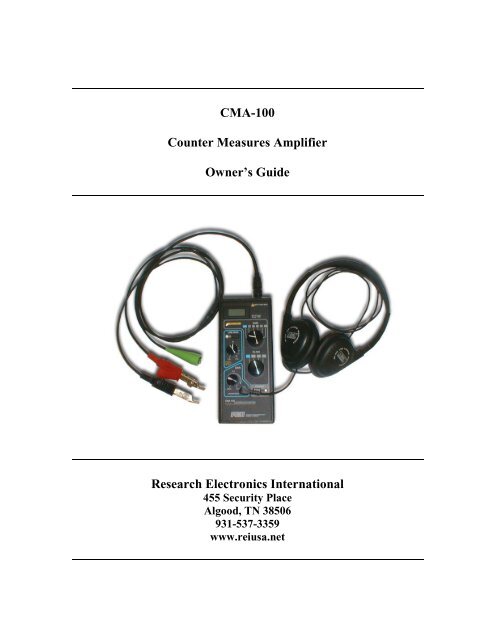
CONTROLS: REI<br />
1. On/Low Battery Indicator<br />
2. Power Switch<br />
3. Filter Selector<br />
4. Gain Selector<br />
5. Test Lead Cable Connector<br />
6. Line Out Jack - 3.5mm<br />
7. Meter<br />
Figure 1<br />
8. Input Attenuator Indicator<br />
9. Line Bias Indicator<br />
10. Line Bias Switch<br />
11. Line Bias Voltage Adjust<br />
12. Headphone Gain<br />
13. Headphone Jack - 3.5mm
CONTROLS: REI<br />
IDENTIFICATION<br />
Please refer to Figure 1 for the following function descriptions.<br />
1. The Power On Indicator is used to identify when the unit is turned on. If the battery<br />
voltage falls below 6.9V, then the LED will extinguish and the battery should be<br />
replaced.<br />
2. The Power Switch turns the unit on and off.<br />
3. The Filter Selector is a 4 position rotary switch, provides different options of filtering<br />
the input audio signal.<br />
A. Flat - Does not filter the input signal, providing a full bandwidth inspection<br />
between 25 and 44kHz.<br />
B. Bandpass - Combines the Lowpass and Highpass in series to create a 3dB<br />
bandpass from 320Hz to 3.2kHz.<br />
C. Low Pass - Allows the passage of frequencies below 3.2kHz and attenuation of<br />
higher frequencies. The effect of this filter is to remove high frequency noise such<br />
as machinery noise, etc…<br />
D. High Pass - Allows the passage of frequencies above 320Hz and attenuation of<br />
lower frequencies. The effect of this filter is to remove low frequency noise such<br />
as AC power line noise.<br />
4. The Gain Selector gives the user two operation modes.<br />
A. Auto - This is automatic gain control (AGC) provides up to 105dB of gain. The<br />
AGC circuit increases the gain during low input signal conditions and decreases<br />
the gain for high input signal conditions. This circuit adapts to provide a proper<br />
audio listening level regardless of the change in input audio level.<br />
B. Manual<br />
1.) Fixed gain setting of 0(unity), 25, 50, 75, and <strong>100</strong>dB.<br />
2.) Useful for situations where signal level has large dynamic range that the user<br />
wants to utilize.<br />
C. In either case, the Input Attenuator will automatically initiate if the input level<br />
exceeds 300 millivolts peak-peak. This will provide up to 30dB of attenuation.<br />
5. The Test Lead Cable Connector is a three-pin keyed connector that insures proper<br />
polarity of the test leads.<br />
6. The Line Out Jack provides a signal out, controlled by the "Headphone Gain ", and<br />
has an output impedance of 600 ohms.
CONTROLS: REI<br />
7. When the Line Bias Generator is turned off, the voltage meter can measure both AC<br />
and DC volts (Note: AC volts are read as RMS values).<br />
Note: When the Line Bias Generator is turned on, the voltage meter will measure a<br />
combination of the voltage in the circuit that the test leads are connected to and the<br />
voltage presented from the Bias Generator. To read only the Bias Generator, remove<br />
the Test Leads from any circuit.<br />
8. The red colored Input Attenuation Indicator will indicate that the input signal is of<br />
sufficiently high level to automatically initiate the input attenuation circuit. This<br />
important function provides attenuation to a high power audio signal so that the gain<br />
circuit will not distort the signal. This automatic attenuator circuit provides<br />
attenuation for audio levels between 300 millivolts and 31 volts. For signals that<br />
exceed 31volts peak-to-peak, distortion will occur.<br />
9. A yellow Line Bias Indicator will indicate the Bias Generator is turned on.<br />
10. The Line Bias Switch will turn the Bias Generator on or off.<br />
11. The Line Bias Voltage Adjust will control the magnitude of the bias voltage. The<br />
mid-position will generate 0V. Turn to the left to generate a negative voltage and<br />
turn to the right to generate a positive voltage. This function is provided specifically<br />
to provide DC voltage to power a potential threat such as an electret microphone or<br />
wiretap device that may be connected to a line. By activating a potential threat, it is<br />
much easier to identify.<br />
12. The Headphone Gain is a volume level control for both the Headphones and the Line<br />
Out. This level control provides up to 15 dB of additional gain.<br />
13. The Headphone Jack is for use with the included headphones.<br />
USING THE <strong>CMA</strong>: REI<br />
Testing for Voltage levels<br />
Unknown wiring should first be evaluated using a voltmeter to ensure that the voltage<br />
does not exceed the ability of the <strong>CMA</strong>. However, if the wiring is known to be lowvoltage<br />
wiring such as Telephone, LAN system, or security system wiring, then the <strong>CMA</strong><br />
can be connected directly to the wiring using the <strong>CMA</strong> test leads and voltage levels will<br />
be displayed directly on the <strong>CMA</strong>.
USING THE <strong>CMA</strong>: REI<br />
Single Line and Balanced Line Connections<br />
The <strong>CMA</strong> provides for connections to either single line systems (typically a single line<br />
with a ground such as coax) or a balanced pair line such as telephone or LAN wiring.<br />
For Single Line systems:<br />
• Connect the Green grounding connector to the Black connector.<br />
• Connect the Black connector to wiring ground.<br />
• Connect the Red connector to the single line to be tested.<br />
For Balanced Pair systems:<br />
• Connect the Green grounding connector to earth ground if available (if not<br />
available, do not connect to anything).<br />
• Connect the Black connect one of the wires to be tested.<br />
• Connect the Red connector to the other wire to be tested.<br />
Signal Power Levels<br />
Signal power levels may vary dramatically. The <strong>CMA</strong> has two systems that allow the unit<br />
to respond automatically to a wide range of audio levels. The automatic input attenuator<br />
prevents gain distortion for situations when the input voltage levels exceed 0.3 volts.<br />
But, more importantly the Automatic Gain Control Function has a dynamic range of<br />
105dB. In basic terms, this means that that the unit can automatically adjust to audio<br />
signals ranging from 2 microvolts to 0.3 volts.<br />
Strong Signal Interference<br />
If the input is attached to an AC voltage greater than 40 volts, the audio content will be<br />
masked.<br />
Signal Frequency Interference<br />
Wiring in a building is very susceptible to interference from ambient electromagnetic<br />
noise sources. The most common type of audio interference is from the AC power lines.<br />
This noise is typically either 50 or 60Hz fundamental frequency; however, there are<br />
harmonic frequency components that also cause interference at <strong>100</strong>/120Hz, 150/180Hz,<br />
and possible up to 200/240Hz. For this reason, the <strong>CMA</strong> has a built-in High Pass filter<br />
that filters out audio noise below 320Hz.<br />
Also, high frequency electromagnetic noise can interfere with audio signals. This type of<br />
higher frequency noise can be generated from industrial machinery, computers, fax<br />
machines, and digital phone systems. Hence, the <strong>CMA</strong> has a built-in High Pass filter that<br />
filters out audio noise above 3,200Hz.<br />
Providing DC Bias<br />
It is a common practice to utilize electret type microphones for audio surveillance, and<br />
electret microphones require a voltage supply in order to function. Therefore, when<br />
evaluating suspect wiring, if the wiring does not have any voltage on the line, it is
ecommended to apply a DC bias voltage to activate any potential microphones. The DC<br />
Bias Voltage should only be used after ensuring that the line does not have an active<br />
USING THE <strong>CMA</strong>: REI<br />
voltage supply. Then, the DC Bias voltage can be switched on and the control knob<br />
slowly turned to both negative and positive directions while listening with the<br />
headphones to see if a microphone is activated.<br />
Using the <strong>CMA</strong> with other probes<br />
The <strong>CMA</strong> can be connected to a variety of other probes.<br />
• Inductive coil - for coupling to an audio signal without making a metallic<br />
connection.<br />
• Contact microphone - for detecting sound within physical structures.<br />
Over voltage protection<br />
If the <strong>CMA</strong>'s input voltage limit is exceeded, then damage will most likely occur that will<br />
make the <strong>CMA</strong> require repairs. The <strong>CMA</strong> case is isolated from an input up to 500V.<br />
Therefore, if the input is allowed to exceed 500 volts then a shock hazard will exist.<br />
Over current protection<br />
When connected to an AC power line, the BIAS GENERATOR should not be activated.<br />
In the event that it is, there are input current limiting devices that will protect the delicate<br />
parts of the <strong>CMA</strong>. After disconnecting the input, it will take several seconds for the<br />
<strong>CMA</strong> to work properly again.
SPECIFICATIONS REI<br />
INPUT IMPEDANCE: 50k ohm balanced<br />
COMMON MODE REJECTION: >75 dB<br />
MAXIMUM USABLE INPUT: 31 Vp-p<br />
PREAMP AUTO ATTENUATOR: 0 to –40 dB (with Input Atten LED)<br />
DYNAMIC RANGE: 145 dB min.<br />
MANUAL GAIN CONTROL: 0,25,50,75,<strong>100</strong> dB<br />
HEADPHONE GAIN CONTROL: 0 to 15 dB<br />
MAXIMUM SYSTEM GAIN: 115 dB<br />
FREQUENCY RESPONSE: 25 Hz to 44 kHz<br />
HIGH PASS FILTER: 320 Hz to 44 kHz<br />
LOW PASS FILTER: 25 Hz to 3.2 kHz<br />
BAND PASS FILTER: 320 Hz to 3.2 kHz<br />
HEADPHONE AUDIO OUTPUT: 16 ohm, 105dB SPL limited<br />
LINEOUT AUDIO OUTPUT: 600 ohm<br />
BIAS CONTROL: 0 to +/-14.5 VDC, 5 mA max (Over current protected,<br />
input Impedance is reduced to 3.6k ohms when bias is<br />
active)<br />
DIGITAL VOLTMETER: 3.5 digit, auto zero, auto polarity, +/-199.9V AC or DC<br />
POWER ON/LOW BATTERY LED LED off @ 6.9V<br />
BATTERY: 9 V ALKALINE (5-30 Hrs typical run time)<br />
MAXIMUM INPUT VOLTAGE: 250 AC/DC<br />
LEAKAGE RESISTANCE TO CASE: >10M ohms<br />
SIZE: 7.3” (185.4mm) x 2.75” (69.8mm) x 1.75” (44.5 mm)<br />
WEIGHT: 12.1-oz (343g)