Technical Paper - Timken
Technical Paper - Timken
Technical Paper - Timken

You also want an ePaper? Increase the reach of your titles
YUMPU automatically turns print PDFs into web optimized ePapers that Google loves.
But, for just about all equipment types, economics<br />
dictate the need for increased power density and im-<br />
proved reliability. A common approach is to attempt to<br />
build in more planets, thereby reducing forces and stress-<br />
es at each mesh point. But, as planets are added, so is<br />
uncertainty about just how much power each planet is<br />
transmitting. Therefore, the safety factors (for example,<br />
K gamma) are applied to maintain conservatism of de-<br />
sign that defeats some of the effort to achieve more pow-<br />
er density.<br />
Alternatively, designers have applied a number of nov-<br />
el designs with various levels of success to build epicy-<br />
clical gearing systems that help distribute loading among<br />
planets more evenly, thereby increasing power density. In<br />
general, such improvements employ components in the<br />
gear train that are elastically compliant and are intended<br />
to compensate for clearance variations without imparting<br />
any negative operating characteristics. Some include:<br />
(1) Flexible ring gears have been applied, but the effective-<br />
ness of this approach is not universal because the radi-<br />
al deflections of the ring gear are not enough to compen-<br />
sate for the clearance (backlash) variations present at the<br />
various mesh points<br />
(2) Floating ring gear system (used in some off-highway<br />
applications)<br />
(3) Floating sun gear<br />
(4) Floating planet carrier<br />
(5) Double helical gear with floating members<br />
(6) Floating planetary gear, also called flexible pin or ab-<br />
breviated to flexpin. [1]<br />
The remainder of this paper will focus around ad-<br />
vancement of number 6 in the form of a new product<br />
called the Integrated Flexpin Bearing (to be referred to<br />
from this point on as the IFB).<br />
What is the Integrated Flexpin<br />
Bearing?<br />
The flexible pin design mentioned on line 8 above was<br />
created in the mid-1960s by British inventor Ray Hicks. It<br />
is based on achieving an equal load distribution among<br />
planets by anchoring them onto a planetary carrier in a<br />
torsionally compliant fashion. Instead of fixing the an-<br />
gular positions of the planet gears, the flexible pins were<br />
designed so that they could deflect independently in a<br />
circumferential direction, which ultimately helps equalize<br />
the force distribution among the planets while transmit-<br />
ting torque at various levels. This feature will be referred<br />
to henceforth in this paper as torsional compliancy.<br />
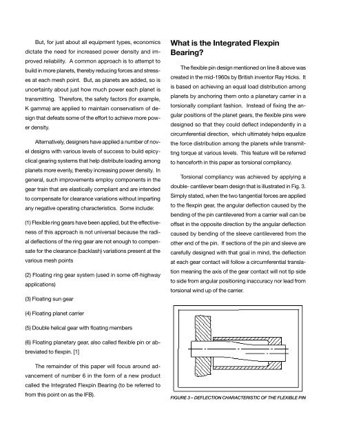
Torsional compliancy was achieved by applying a<br />
double- cantilever beam design that is illustrated in Fig. 3.<br />
Simply stated, when the two tangential forces are applied<br />
to the flexpin gear, the angular deflection caused by the<br />
bending of the pin cantilevered from a carrier wall can be<br />
offset in the opposite direction by the angular deflection<br />
caused by bending of the sleeve cantilevered from the<br />
other end of the pin. If sections of the pin and sleeve are<br />
carefully designed with that goal in mind, the deflection<br />
at each gear contact will follow a circumferential transla-<br />
tion meaning the axis of the gear contact will not tip side<br />
to side from angular positioning inaccuracy nor lead from<br />
torsional wind up of the carrier.<br />
FIGURE 3 – DEFLECTION CHARACTERISTIC OF THE FLEXIBLE PIN