installing the composite post sleeve assemble and install ... - Fiberon
installing the composite post sleeve assemble and install ... - Fiberon
installing the composite post sleeve assemble and install ... - Fiberon

You also want an ePaper? Increase the reach of your titles
YUMPU automatically turns print PDFs into web optimized ePapers that Google loves.
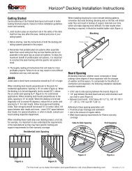
INSTALLING THE COMPOSITE POST SLEEVE<br />
Walking surface<br />
Base Cove<br />
Moulding<br />
Prior to <strong>install</strong>ation consult building code requirements for proper <strong>post</strong> <strong>install</strong>ation. Local building codes supersede any <strong>and</strong> all recommendations in <strong>the</strong> following<br />
guide. Before <strong><strong>install</strong>ing</strong> <strong>the</strong> Composite Post Sleeve, review <strong>the</strong> <strong>install</strong>ation instructions of <strong>the</strong> railing system planned for <strong>the</strong> project.<br />
THE COMPOSITE POST SLEEVE IS A NON-LOAD BEARING POST AND<br />
SHOULD NOT BE USED AS A STRUCTURAL SUPPORT OF ANY KIND.<br />
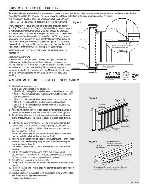
The Composite Post Sleeve is designed to slide over a structurally sound 4” x<br />
4” (3.5” x 3.5” actual) wood <strong>post</strong>. The wood <strong>post</strong> should be plumb <strong>and</strong> true prior<br />
to <strong><strong>install</strong>ing</strong> <strong>the</strong> Composite Post Sleeve. When fully <strong>install</strong>ed <strong>the</strong> Composite<br />
Post Sleeve should sit flush on <strong>the</strong> walking surface <strong>and</strong> should not extend more<br />
than 1” above <strong>the</strong> top of <strong>the</strong> wood support <strong>post</strong> (figure 1). Trim wood <strong>post</strong> as<br />
appropriate. Before attaching <strong>the</strong> guard rail to <strong>the</strong> Composite Post Sleeve, be<br />
sure to <strong>install</strong> <strong>the</strong> Base Cove Moulding as shown in figure 2. The Guard Rail<br />
System should only be secured to code compliant <strong>post</strong>s. Securing <strong>the</strong> Guard<br />
Rail System to ano<strong>the</strong>r structure (i.e. building) is not recommended.<br />
BASE COVE MOULDING CANNOT BE INSTALLED AFTER RAILING IS<br />
ATTACHED!<br />
CODE CONSIDERATIONS<br />
The Base Cove Moulding requires a minimum spacing of 3” between <strong>the</strong><br />
walking surface <strong>and</strong> <strong>the</strong> lower subrail. Some building codes may require a<br />
spacing of less than 3”. In <strong>the</strong>se instances, <strong>the</strong> lower subrail mounting brackets<br />
will interfere with <strong>the</strong> Base Cove Moulding. The <strong>install</strong>er has two ways to<br />
overcome this situation: (1) Notch <strong>the</strong> Base Cove Moulding to allow <strong>the</strong> lower<br />
leg of <strong>the</strong> bracket to sit against <strong>the</strong> <strong>post</strong>, or (2) Do not use <strong>the</strong> Base Cove<br />
Moulding.<br />
ASSEMBLE AND INSTALL THE COMPOSITE RAILING SYSTEM<br />
1. Identify all hardware components:<br />
a. (4) In-Line Brackets (<strong>post</strong> to rail connections)<br />
b. (8) #10 - 3/4 inch long Phillip’s head screws (bracket to lower subrail only)<br />
c. (8) # 10 - 1 3/8 inch long Phillip’s head screws (bracket to top rail & upper<br />
subrail assembly only)<br />
d. (8) # 10 - 1 3/8 inch long Phillip’s head screws (upper subrail to top rail)<br />
e. (17) # 10 - 2 inch long Phillip’s head screws (bracket to <strong>post</strong> only)<br />
f. (42) # 10 - 1 3/4 inch long Phillip’s head screws (rails to balusters only)<br />
g. (1) Phillip’s head driver<br />
2. Measure <strong>the</strong> distance between <strong>install</strong>ed <strong>post</strong>s at various heights. Check to<br />
determine <strong>the</strong> distance does not vary more than 1/16 of an inch (figure 3).<br />
3. Trim <strong>the</strong> three rail components to fit between <strong>the</strong> <strong>post</strong>s, i.e., top rail, upper<br />
subrail <strong>and</strong> lower subrail. Cut should be square to insure a good fit with <strong>the</strong><br />
<strong>post</strong>.<br />
4. Determine <strong>the</strong> spacing for balusters. For a full 8 feet guardrail length, <strong>the</strong><br />
baluster spacing is 4.5” on center <strong>and</strong> equal spacing at both ends of <strong>the</strong><br />
guardrail (3 inches). Typically, building codes requires spacing between<br />
balusters less than 4 inches.<br />
NOTE: Don’t position screws near <strong>the</strong> end of <strong>the</strong> rails which is reserved for<br />
rail/<strong>post</strong> bracket <strong>install</strong>ation (minium distance = 2-1/4”).<br />
5. Mark <strong>the</strong> center location for each baluster on <strong>the</strong> upper subrail. Transfer <strong>the</strong>se<br />
locations to <strong>the</strong> lower subrail by laying <strong>the</strong> lower subrail beside <strong>the</strong> upper<br />
subrail as shown in figure 4.<br />
6. Drill clearance holes using a 7/32 inch diameter drill bit for all pre-marked<br />
locations.<br />
7. Drill 3/8 inch counter-bored holes from bottom side of lower subrail<br />
approximately 1/2 inch deep for all hole locations in <strong>the</strong> lower subrail (figure<br />
5). This step is optional if attempting to hide <strong>the</strong> screw heads.<br />
8. Trim all 32 inch balusters to <strong>the</strong> desired length.<br />
9. Using a 1/8” bit, drill holes that are 2 inches long, centered in each end of <strong>the</strong><br />
baluster<br />
10. Place#10 -1 ¾ inch long Phillip’s screw into each of <strong>the</strong> counter-bored holes in<br />
<strong>the</strong> lower subrail.<br />
11. Secure a baluster in each location of <strong>the</strong> lower subrail. In <strong>the</strong> two part system,<br />
ensure balusters are against <strong>the</strong> baluster stop.<br />
**Do Not Over Tighten Screws**<br />
Figure 1<br />
Post Cap<br />
Post<br />
Walking surface<br />
4“x4” Wood Post<br />
Base Cove<br />
Moulding<br />
Figure 3<br />
Post<br />
Figure 4<br />
Distance depends on<br />
code requirements<br />
Distance depends on<br />
Two code Part requirements System<br />
Measure Width<br />
Accurately in three<br />
different places<br />
Balusters<br />
Marked<br />
Screw Locations<br />
Figure 3<br />
Two Part System<br />
Measurement (a)<br />
(a)<br />
4.5”<br />
Post<br />
Top<br />
Rail<br />
Baluster Stop<br />
Upper<br />
Measure Width<br />
Subrail Lower<br />
Accurately in three<br />
Subrail<br />
different places<br />
Post<br />
Be sure to transfer measurements from Upper to<br />
Lower Subrail with rails oriented as shown.<br />
Balusters<br />
Interference<br />
Walking surface<br />
If distance is less than 3”, moulding<br />
will interfere with brackets.<br />
(a)<br />
Post<br />
Figure 2<br />
Top<br />
Rail<br />
Upper<br />
Subrail<br />
Lower<br />
Subrail<br />
(a)<br />
should be same.<br />
Check building<br />
codes for<br />
baluster spacing<br />
Use <strong>the</strong> V-Notch to<br />
locate baluster holes<br />
with desired spacing.<br />
Upper<br />
Subrail<br />
Lower<br />
Subrail<br />
(a)<br />
REV 12/09<br />
Measurement (a)<br />
should be same.<br />
Check building<br />
codes for<br />
baluster spacing
Assemble <strong>and</strong> Install Composite Railing System Continued<br />
12. Secure <strong>the</strong> balusters in each corresponding location of <strong>the</strong> subrail using #10<br />
- 1 ¾ inch long Phillip’s screws. In <strong>the</strong> two part system, ensure balusters are<br />
against <strong>the</strong> baluster stop.<br />
**Do Not Over Tighten Screws**<br />
13. Mark 8 hole locations equally spaced on <strong>the</strong> top surface of <strong>the</strong> subrail. Choose<br />
locations mid-point between <strong>the</strong> balusters.<br />
14. Drill using a 7/32 inch diameter drill bit through <strong>the</strong> subrail.<br />
15. Drill 3/8 inch counter-bored holes from <strong>the</strong> baluster side of <strong>the</strong> upper subrail,<br />
approximately 1/2 inch deep for <strong>the</strong> eight hole locations in <strong>the</strong> upper subrail.<br />
This step is optional if attempting to hide <strong>the</strong> screw heads (figure 5).<br />
16. Center <strong>the</strong> top rail on <strong>the</strong> upper subrail. The baluster screw heads will help you<br />
with proper alignment.<br />
17. Using <strong>the</strong> holes created in step 14, mark hole positions on <strong>the</strong> top rail.<br />
18. Using a 1/8” bit, drill holes that are 3/4 inch deep into <strong>the</strong> top rail.<br />
19. Secure <strong>the</strong> top rail to <strong>the</strong> assembly using 8 # 10 -1 3/8 inch long Phillip’s<br />
screws.<br />
**Do NOT Over Tighten Screws**<br />
** NOTE: If you are using <strong>the</strong> Composite Post Sleeve Moulding, it must<br />
be <strong>install</strong>ed on <strong>the</strong> <strong>post</strong> before continuing <strong>the</strong> rail <strong>install</strong>ation. It cannot be<br />
<strong>install</strong>ed after <strong>the</strong> railing is attached to <strong>the</strong> <strong>post</strong>! Refer to “Installing Composite<br />
Post Sleeve” on o<strong>the</strong>r side of this page.<br />
20. Using mounting bracket as a template, center <strong>the</strong> bracket on <strong>the</strong> bottom<br />
surface of <strong>the</strong> lower subrail <strong>and</strong> 1/16 inch from <strong>the</strong> end of <strong>the</strong> lower subrail<br />
(figure 6). This promotes a tight fit when securing <strong>the</strong> rail section to <strong>the</strong> <strong>post</strong>.<br />
21. Mark <strong>the</strong> four hole locations on <strong>the</strong> lower subrail <strong>and</strong> pre-drill using a 1/8” drill<br />
bit, approximately ½ inch deep.<br />
22. Attach <strong>the</strong> bracket to <strong>the</strong> lower subrail using 4 -#10 - ¾ inch long screws,<br />
**Do Not Over Tighten Screws**<br />
**NOTE: If longer screws are used, <strong>the</strong> screws may be exposed on <strong>the</strong> top<br />
surface of <strong>the</strong> lower subrail. **<br />
23. Repeat steps 20 - 22 for <strong>the</strong> o<strong>the</strong>r end of <strong>the</strong> bottom guardrail.<br />
24. Repeat steps 20- 23 for top rail & upper subrail assembly by centering <strong>the</strong><br />
bracket on <strong>the</strong> bottom surface of <strong>the</strong> top rail & upper subrail assembly. Use<br />
4 - #10 - 1 3/8 inch long screws to secure <strong>the</strong> bracket to <strong>the</strong> top rail & upper<br />
subrail assembly.<br />
25. Cut two crush blocks from excess baluster materials. Check building code<br />
requirements for maximum spacing between <strong>the</strong> walking surface <strong>and</strong> <strong>the</strong> lower<br />
subrail; typically <strong>the</strong> maximum heights range between 2 - 4 inches.<br />
26. Space <strong>the</strong> crush blocks equidistant between <strong>the</strong> <strong>post</strong>s (figure 7).<br />
27. Center <strong>the</strong> <strong>assemble</strong>d section between <strong>the</strong> <strong>post</strong>s while laying <strong>the</strong> <strong>assemble</strong>d<br />
section onto <strong>the</strong> crush blocks.<br />
28. Ensure <strong>the</strong> top rail & lower subrail are level.<br />
29. Mark <strong>the</strong> screw locations on <strong>the</strong> <strong>post</strong>s for both ends of <strong>the</strong> lower subrail using<br />
<strong>the</strong> mounting brackets as templates.<br />
30. Drill holes using a 1/8” drill bit at marked screw locations approximately 2<br />
inches deep. If needed, remove <strong>assemble</strong>d section for ease of drilling.<br />
31. Attach brackets to <strong>the</strong> <strong>post</strong> with 4 - 2” long screws at each end of <strong>the</strong> lower<br />
subrail.<br />
**Do Not Over Tighten Screws**<br />
32. Center <strong>the</strong> top rail <strong>and</strong> upper subrail on <strong>the</strong> <strong>post</strong>. Mark hole locations on <strong>the</strong><br />
<strong>post</strong>s using <strong>the</strong> brackets as a template.<br />
33. Drill holes using a 1/8”drill bit at marked screw locations approximately 2<br />
inches deep. If needed, slightly pull <strong>the</strong> <strong>assemble</strong>d section inward toward <strong>the</strong><br />
deck to accommodate drilling into <strong>the</strong> <strong>post</strong>.<br />
34. Attach <strong>the</strong> rail bracket to <strong>the</strong> <strong>post</strong> with 4 - 2” long screws at each end of <strong>the</strong><br />
upper subrail.<br />
**Do Not Over Tighten Screws**<br />
35. Repeat 33 & 34 steps for <strong>the</strong> o<strong>the</strong>r upper subrail bracket.<br />
36. Apply adhesive to <strong>the</strong> crush blocks <strong>and</strong> secure to <strong>the</strong> lower subrail.<br />
37. Secure <strong>post</strong> caps using adhesive on <strong>the</strong> inside corners of <strong>the</strong> <strong>post</strong> cap.<br />
38. Push caps firmly onto <strong>the</strong> <strong>post</strong>. Wipe excess adhesive off <strong>the</strong> <strong>post</strong> <strong>sleeve</strong>.<br />
Figure 5<br />
Baluster<br />
Stop<br />
Baluster<br />
Stop<br />
V-notch<br />
center line<br />
Figure 6<br />
Lower<br />
Subrail<br />
Figure 7<br />
(a)<br />
Crush<br />
Blocks<br />
Step 15<br />
Step 7<br />
Distance (a) should be same.<br />
(a)<br />
(a)<br />
Top Rail<br />
Upper<br />
Subrail<br />
Drill 3/8” counter bore holes 1/2” deep prior to fastening<br />
in steps 12 & 19 (this step is not required, but if you want to<br />
<strong>install</strong> <strong>the</strong> crush block directly under <strong>the</strong> balluster, you<br />
must counter bore those holes).<br />
Baluster<br />
Lower<br />
Subrail<br />
REV 12/09
ASSEMBLE AND INSTALL THE COMPOSITE STAIR SYSTEM<br />
1. Identify all hardware components:<br />
a. (4) Hinged Brackets (<strong>post</strong> to rail connections)<br />
b. (8) #10 - 3/4 inch long Phillip’s head screws (bracket to lower subrail only)<br />
c. (8) #10 - 1 3/8 inch long Phillip’s head screws (bracket to upper subrail<br />
only)<br />
d. (8) #10 - 1 3/8 inch long Phillip’s head screws (upper subrail to top rail)<br />
e. (17) #10 - 2 inch long Phillip’s head screws (bracket to <strong>post</strong> only)<br />
f. (42) #10 - 1 3/4 inch long Phillip’s head screws (rails to balusters only)<br />
g. (1) Phillip’s head driver<br />
2. Measure <strong>the</strong> distance between <strong>install</strong>ed <strong>post</strong>s at various heights. Check to<br />
determine <strong>the</strong> distance does not vary more than 1/16 of an inch.<br />
3. Lay lower subrail on stairs. Mark angle on rail (figure 3).<br />
4. Cut <strong>the</strong> lower subrail to <strong>the</strong> marked angle <strong>and</strong> to proper length. Check fit at<br />
both ends.<br />
5. Using <strong>the</strong> same angle, cut <strong>the</strong> upper subrail <strong>and</strong> top rail to length <strong>and</strong> check<br />
fit.<br />
6. Determine <strong>the</strong> spacing for balusters. The baluster spacing is 4.5” on center<br />
<strong>and</strong> equal spacing at <strong>the</strong> guardrail ends. Typically, building codes requires<br />
spacing between balusters less than 4 inches.<br />
7. Mark <strong>the</strong> location for each baluster on <strong>the</strong> top surface of <strong>the</strong> upper subrail.<br />
Use <strong>the</strong> V-notch on <strong>the</strong> two part system. Transfer <strong>the</strong> baluster locations<br />
from <strong>the</strong> upper subrail to <strong>the</strong> top surface of <strong>the</strong> lower subrail. Make sure <strong>the</strong><br />
distance from <strong>the</strong> baluster stop can accommodate <strong>the</strong> location of <strong>the</strong> baluster<br />
on <strong>the</strong> two part system.<br />
NOTE: Don’t position screws near <strong>the</strong> end of <strong>the</strong> rails which is reserved for<br />
rail/<strong>post</strong> bracket <strong>install</strong>ation (minium distance = 2-1/4”).<br />
NOTE: The hole locations should be <strong>the</strong> same on <strong>the</strong> top surface of <strong>the</strong> upper<br />
<strong>and</strong> lower subrails with respect to <strong>the</strong> end of <strong>the</strong> rail <strong>and</strong> baluster stop (figure<br />
4).<br />
8. Drill clearance holes at <strong>the</strong> appropriate angle through <strong>the</strong> upper subrail using a<br />
7/32 inch diameter drill bit for all hole locations.<br />
9. Drill clearance holes at <strong>the</strong> appropriate angle through <strong>the</strong> lower subrail using a<br />
7/32 inch diameter drill bit for all hole locations.<br />
10. Drill 3/8 inch counter-bored holes on <strong>the</strong> bottom surface of <strong>the</strong> lower subrail<br />
1/2 inch deep for all hole locations. This step is optional if attempting to hide<br />
<strong>the</strong> head of <strong>the</strong> screws (figure 5).<br />
11. Trim all 32 inch balusters to <strong>the</strong> desired length at <strong>the</strong> appropriate angle.<br />
12. Drill 1/8” holes that are 2 inches long, centered in each end of <strong>the</strong> baluster.<br />
The drilled holes should follow <strong>the</strong> centerline of <strong>the</strong> baluster.<br />
13. Place #10 -1 ¾ inch long Phillip’s screws into each counter-bored hole in <strong>the</strong><br />
lower subrail.<br />
14. Secure a baluster in each location of <strong>the</strong> lower subrail. On <strong>the</strong> two part<br />
system, be sure <strong>the</strong> baluster rests firmly against <strong>the</strong> raised baluster stop on<br />
<strong>the</strong> lower subrail.<br />
15. Secure <strong>the</strong> balusters in each corresponding location on <strong>the</strong> upper subrail.<br />
On <strong>the</strong> two part system, be sure <strong>the</strong> baluster rests firmly against <strong>the</strong> raised<br />
baluster stop on <strong>the</strong> upper subrail.<br />
16. Mark 8 hole locations equally spaced along <strong>the</strong> top surface of <strong>the</strong> upper<br />
subrail. Use <strong>the</strong> v-notch of <strong>the</strong> two part system for a center line. The marked<br />
locations should be near mid-point between balusters. After drilling, <strong>the</strong> hole<br />
should be at <strong>the</strong> midpoint between balusters on <strong>the</strong> bottom surface of <strong>the</strong><br />
upper subrail.<br />
17. Drill clearance holes using a 7/32 inch diameter drill bit in <strong>the</strong> upper subrail at<br />
<strong>the</strong> appropriate angle for <strong>the</strong> staircase.<br />
18. Drill 3/8 inch counter-bored holes on <strong>the</strong> bottom surface of <strong>the</strong> upper subrail<br />
1/2 inch deep for all hole locations. This step is optional if attempting to hide<br />
<strong>the</strong> head of <strong>the</strong> screws (figure 5).<br />
19. Place <strong>the</strong> top rail on <strong>the</strong> subrail/baluster assembly (figure 5).<br />
Figure 3<br />
Lower<br />
Subrail<br />
Figure 4<br />
Deck<br />
Marked<br />
Screw Locations<br />
Stair Surface<br />
Stringers<br />
Use <strong>the</strong> V-Notch to<br />
locate baluster holes<br />
with desired spacing.<br />
4.5”<br />
Lower<br />
Subrail Upper<br />
Subrail<br />
Cut Angle<br />
Baluster Stop<br />
Figure 5<br />
Baluster<br />
Stop<br />
Baluster<br />
Stop<br />
V-notch<br />
center line<br />
Figure 6<br />
Rim Joists<br />
Typical Stair Layout:<br />
� 7-inch rise<br />
� 11-inch run<br />
� 32-degree angle<br />
Be sure to transfer measurements from Sub-Rail to<br />
Bottom Rail with rails oriented as shown.<br />
Step 18<br />
Step 10<br />
Drill 3/8” counter bore holes 1/2” deep<br />
prior to fastening in steps 14 & 22 (optional)<br />
Top Rail<br />
Upper<br />
Subrail<br />
Baluster<br />
Lower<br />
Subrail<br />
REV 12/09
Assemble <strong>and</strong> Install Composite Stair System Continued<br />
20. Mark hole positions on <strong>the</strong> bottom of <strong>the</strong> top rail.<br />
21. Using a 1/8” bit, drill holes at <strong>the</strong> appropriate angle that are 1 inch deep into<br />
<strong>the</strong> top rail.<br />
22. Secure <strong>the</strong> top rail to <strong>the</strong> assembly using 8 #10 - 1 3/8 inch long Phillip’s<br />
screws.<br />
**Do Not Over Tighten Screws**<br />
** NOTE: If you are using <strong>the</strong> Composite Post Sleeve Moulding, it must<br />
be <strong>install</strong>ed on <strong>the</strong> <strong>post</strong> before continuing <strong>the</strong> rail <strong>install</strong>ation. It cannot be<br />
<strong>install</strong>ed after <strong>the</strong> railing is attached to <strong>the</strong> <strong>post</strong>! Refer to “Installing Composite<br />
Post Sleeve” on o<strong>the</strong>r side of this page.<br />
23. Using hinged bracket as a template, place <strong>the</strong> bracket on <strong>the</strong> bottom surface<br />
of <strong>the</strong> lower subrail 1/16 inch from <strong>the</strong> rail edge. The 1/16 inch spacing<br />
promotes a tight fit when securing <strong>the</strong> rail to <strong>the</strong> <strong>post</strong> (figure 6).<br />
24. Mark <strong>the</strong> four hole locations on <strong>the</strong> lower subrail <strong>and</strong> pre-drill a ¾ inch deep<br />
hole using a 1/8” drill bit.<br />
25. Attach <strong>the</strong> bracket to <strong>the</strong> lower subrail using 4 -#10 - ¾ inch long screws.<br />
**Do Not Over Tighten Screws**<br />
26. Repeat steps 23 -25 for <strong>the</strong> o<strong>the</strong>r end of <strong>the</strong> lower subrail.<br />
27. Repeat steps 23 -26 for upper subrail/top rail assembly by placing <strong>the</strong> bracket<br />
on <strong>the</strong> bottom surface of <strong>the</strong> upper subrail.<br />
28. Lay <strong>the</strong> <strong>assemble</strong>d section on a ½ inch thick wood spacer to facilitate <strong>the</strong><br />
<strong>install</strong>ation (figure 7).<br />
29. Center <strong>the</strong> <strong>assemble</strong>d section between <strong>the</strong> <strong>post</strong>s. Check building code<br />
requirements for maximum spacing for staircase between <strong>the</strong> stairs <strong>and</strong><br />
guardrail; typically it is limited to a 6 inch sphere.<br />
30. Mark <strong>the</strong> screw locations of <strong>the</strong> lower subrail on <strong>the</strong> <strong>post</strong>s using <strong>the</strong> brackets<br />
as templates.<br />
31. Drill holes using a 1/8” drill bit at marked screw locations. If needed, remove<br />
<strong>assemble</strong>d section for ease of drilling.<br />
32. Attach lower subrail/<strong>post</strong> brackets to <strong>the</strong> <strong>post</strong>s with 4 #10- 2” long screws on<br />
each end of <strong>the</strong> guardrail.<br />
**Do Not Over Tighten Screws**<br />
33. Center <strong>the</strong> top rail on <strong>the</strong> <strong>post</strong>. Mark hole locations on <strong>the</strong> <strong>post</strong>s using <strong>the</strong><br />
brackets as templates.<br />
34. Drill holes using a 1/8”drill bit at marked screw locations. If needed, pull <strong>the</strong><br />
<strong>assemble</strong>d section towards <strong>the</strong> stairs for ease of drilling.<br />
35. Attach top rail/<strong>post</strong> brackets to <strong>the</strong> <strong>post</strong>s with 4 #10- 2” long screws on each<br />
end of guardrail.<br />
**Do Not Over Tighten Screws**<br />
36. Secure <strong>post</strong> caps using adhesive on <strong>the</strong> inside corners of <strong>the</strong> <strong>post</strong> cap <strong>and</strong><br />
position <strong>the</strong> cap onto <strong>the</strong> <strong>post</strong>.<br />
37. Push <strong>the</strong> caps firmly onto <strong>the</strong> <strong>post</strong>. Wipe excess adhesive off <strong>the</strong> <strong>post</strong>.<br />
center line Lower<br />
Subrail<br />
Figure 6<br />
Lower<br />
Subrail<br />
Figure 7<br />
Post<br />
Step 10<br />
Drill 3/8” counter bore holes 1/2” deep<br />
prior to fastening in steps 14 & 22 (optional)<br />
MAKE SURE POSTS ARE PLUMB<br />
Center <strong>the</strong> rail<br />
between <strong>post</strong>s<br />
Lower<br />
Subrail<br />
Top Rail<br />
1/2” Wood Spacer<br />
Post<br />
Cap<br />
Post<br />
Stair<br />
Brackets<br />
Balusters<br />
Base Cove<br />
Moulding<br />
REV 12/09