Agent Release Control Panel - SEVO Systems
Agent Release Control Panel - SEVO Systems
Agent Release Control Panel - SEVO Systems
You also want an ePaper? Increase the reach of your titles
YUMPU automatically turns print PDFs into web optimized ePapers that Google loves.
<strong>Agent</strong> <strong>Release</strong> <strong>Control</strong> <strong>Panel</strong><br />
Designed with:<br />
3M Novec 1230<br />
Fire Protection Fluid<br />
System Capacity<br />
• Annunciators: 8<br />
Electrical Specifi cations<br />
• RP-2002 (FLPS-7 Power Supply): 120 VAC, 60 Hz, 3.66 amps<br />
• RP-2002E (FLPS-7 Power Supply): 240 VAC, 50 Hz, 2.085 amps<br />
• Wire size: minimum 14 AWG (2.0 mm²) with 600 V insulation, supervised,<br />
nonpower-limited<br />
Cabinet Specifi cations<br />
Door: 19.26” (48.92 cm.) high x 16.82” (42.73 cm.) wide x 0.72” (1.82 cm.)<br />
deep. Backbox: 19.00” (48.26 cm.) high x 16.65” (42.29 cm.) wide x 5.25”<br />
(13.34 cm.) deep. Trim Ring (TR- CE): 22.00” (55.88 cm.) high x 19.65”<br />
(49.91 cm.) wide.<br />
Shipping Specifi cations<br />
Dimensions:<br />
– Height 20.00” (50.80cm)<br />
– Width 22.50” (57.15cm)<br />
– Depth 8.50” (21.59cm)<br />
Temperature and Humidity Ranges<br />
This system meets NFPA requirements for operation at 0 – 49°C/32 – 120°F<br />
and at a relative humidity 93% ± 2% RH (noncondensing) at 32°C ± 2°C (90°F<br />
± 3°F). However, the useful life of the system’s standby batteries and the<br />
electronic components may be adversely affected by extreme temperature<br />
ranges and humidity. Therefore, it is recommended that this system and its<br />
peripherals be installed in an environment with a normal room temperature of<br />
15 – 27°C/60 – 80°F.<br />
NFPA Standards<br />
The RP-2002(E) complies with the following NFPA 72 Fire Alarm <strong>Systems</strong><br />
requirements:<br />
– NFPA 12 CO2 Extinguishing <strong>Systems</strong><br />
– NFPA 12A Halon 1301 Extinguishing <strong>Systems</strong><br />
– NFPA 12B Halon 1211 Extinguishing <strong>Systems</strong><br />
– NFPA 72 National Fire Alarm Code for Local Fire Alarm<br />
<strong>Systems</strong> and Remote Station Fire Alarm <strong>Systems</strong> (requires an optional<br />
Remote Station Output Module)<br />
– NFPA 2001 Clean <strong>Agent</strong> Fire Extinguishing <strong>Systems</strong><br />
Agency Listings and Approvals<br />
The listings and approvals below apply to the basic RP- 2002(E) control<br />
panels. In some cases, certain modules may not be listed by certain approval<br />
agencies, or listing may be in process. Consult factory for latest listing status.<br />
• UL: S635<br />
• FM approved<br />
• CSFM: 7165-0028:0245<br />
• MEA: 333-07-E<br />
• Seismic Listing: Reference certifi ciate of compliance<br />
VMA - 45894-01 by the VMC Group<br />
NOTE: For ULC-listed model, see DN-60444.<br />
RP-2002(E)<br />
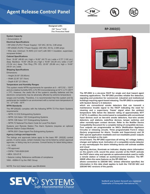
The RP-2002 is a six-zone FACP for single and dual hazard agent<br />
releasing applications. The RP-2002 provides reliable fi re detection,<br />
signaling and protection for commercial, industrial and institutional<br />
buildings requiring agent-based releasing. The RP-2002 is compatible<br />
with System Sensor’s i3 detectors<br />
which are conventional smoke detectors that can transmit a<br />
maintenance trouble signal to the FACP indicating the need for<br />
cleaning and a supervisory ‘freeze’ signal when the ambient<br />
temperature falls below the detector rating of approximately 45°F<br />
(7.22°C). In addition, the control panel is compatible with conventional<br />
input devices such as two-wire smoke detectors, four-wire smoke<br />
detectors, pull stations, waterfl ow devices, tamper switches and<br />
other normally-open contact devices. Refer to the Notifi er Device<br />
Compatibility Document for a complete listing of compatible devices.<br />
Four outputs are programmable as NACs (Notifi cation Appliance<br />
Circuits) or releasing circuits. Three programmable Form-C relays<br />
(factory programmed for Alarm, Trouble and Supervisory) and 24<br />
VDC special application resettable and non-resettable power outputs<br />
are also included on the main<br />
circuit board. The RP-2002 supervises all wiring, AC voltage, battery<br />
charger and battery level. Activation of a compatible smoke detector<br />
or any normallyopen fi re alarm initiating device will activate audible<br />
and visual<br />
signaling devices, illuminate an indicator, display alarm information<br />
on the panel’s LCD, sound the piezo sounder at the FACP, activate<br />
the FACP alarm relay and operate an optionalmmodule used to notify<br />
a remote station or initiate an auxiliarymcontrol function. The RP-<br />
2002E offers the same features as the RP-2002 but<br />
allows connection to 220/240 VAC. Unless otherwise specifi ed, the<br />
information in this data sheet applies to both the 110/120 VAC and<br />
220/240 VAC versions of the panels.<br />
Notifi er® and System Sensor® are registered<br />
trademarks of Honeywell International Inc.
<strong>Agent</strong> <strong>Release</strong> <strong>Control</strong> <strong>Panel</strong><br />
Designed with:<br />
3M Novec 1230<br />
Fire Protection Fluid<br />
Features<br />
• Listed to UL Standard 864, 9th edition.<br />
• FM Approved.<br />
• Designed for agent releasing standards NFPA 12, 12A,<br />
12B, and 2001.<br />
• Meets International Building Code (IBC) seismic requirements.<br />
• Disable/Enable control per input zone and output zone.<br />
• Extensive transient protection.<br />
• Dual hazard operation.<br />
• Adjustable pre-discharge, discharge and waterfl ow delay<br />
timers.<br />
• Cross-zone (double-interlock) capability.<br />
• Six programmable Style B (Class B) IDCs (Initiating Device<br />
Circuit).<br />
• System Sensor i3 series detector compatible.<br />
• Four programmable Style Y (Class B) output circuits - (special<br />
application power).<br />
• Strobe synchronization:<br />
– System Sensor<br />
– Wheelock<br />
– Gentex<br />
– Faraday<br />
– Amseco<br />
• Three programmable Form-C relays.<br />
• 7.0 amps total 24 VDC output current.<br />
• Resettable and non-resettable output power.<br />
• Built-in Programmer.<br />
• ANN-BUS connector for communication with optional<br />
devices (up to 8 total of any of the following):<br />
– N-ANN-80 Remote LCD Annunciator<br />
– N-ANN-I/O LED Driver<br />
– N-ANN-S/PG Printer Module<br />
– N-ANN-RLY Relay Module<br />
– N-ANN-LED Annunciator Module<br />
• 80-character LCD display (backlit).<br />
• Real-time clock/calendar with daylight savings time control.<br />
• History log with 256 event storage.<br />
• Piezo sounder for alarm, trouble and supervisory.<br />
• 24 volt operation.<br />
• Low AC voltage sense.<br />
• Outputs Programmable for:<br />
– Releasing Circuits or NACS<br />
RP-2002(E)<br />
• NACs programmable for:<br />
– Silence Inhibit<br />
– Auto-Silence<br />
– Strobe Synchronization<br />
– Selective Silence (horn-strobe mute)<br />
– Temporal or Steady Signal<br />
– Silenceable or Non-silenceable<br />
– <strong>Release</strong> Stage Sounder<br />
Page 2 of 4 — DN-60240:C1 • 06/14/2011<br />
• Automatic battery charger with charger supervision.<br />
• Optional Dress <strong>Panel</strong> DP-51050 (red).<br />
• Optional Trim Ring TR-CE (red) for semi-fl ush mounting the<br />
cabinet.<br />
• Optional N-CAC-5X Class A Converter Module for Outputs<br />
and IDCs.<br />
• Optional 4XTM Municipal Box Transmitter Module.<br />
• Optional Digital Alarm Communicators (411, 411UD,<br />
411UDAC).<br />
• Optional ANN-SEC card for a secondary ANN-BUS.<br />
PROGRAMMING AND SOFTWARE:<br />
• Custom English labels (per point) may be manually entered<br />
or selected from an internal library fi le.<br />
• Programmable Abort operation.<br />
• Three programmable Form-C relay outputs.<br />
• Pre-programmed and custom application templates.<br />
• Continuous fi re protection during online programming at the<br />
front panel.<br />
• Program Check automatically catches common errors not<br />
linked to any zone or input point.<br />
USER INTERFACE:<br />
• Integral 80-character LCD display with backlighting.<br />
• Real-time clock/calendar with automatic daylight savings<br />
adjustments.<br />
• ANN-Bus for connection to remote annunciators.<br />
• Audible or silent walk test capabilities.<br />
• Piezo sounder for alarm, trouble, and supervisory.<br />
Notifi er® and System Sensor® are registered<br />
trademarks of Honeywell International Inc.
<strong>Agent</strong> <strong>Release</strong> <strong>Control</strong> <strong>Panel</strong><br />
Designed with:<br />
3M Novec 1230<br />
Fire Protection Fluid<br />
<strong>Control</strong>s and Indicators<br />
LED INDICATORS<br />
• FIRE ALARM (red).<br />
• SUPERVISORY (yellow).<br />
• TROUBLE (yellow).<br />
• AC POWER (green).<br />
• ALARM SILENCED (yellow).<br />
• DISCHARGED (red).<br />
• PRE-DISCHARGE (red indicator).<br />
• ABORT (yellow indicator).<br />
CONTROL BUTTONS<br />
• ACKNOWLEDGE.<br />
• ALARM SILENCE.<br />
• SYSTEM RESET (lamp test).<br />
• DRILL.<br />
AC Power – TB1<br />
• RP-2002: 120 VAC, 60 Hz, 3.66 amps.<br />
• RP-2002E: 240 VAC, 50 Hz, 2.085 amps.<br />
• Wire size: minimum #14 AWG (2.0 mm2) with 600V insulation.<br />
• Supervised, nonpower-limited.<br />
Battery (sealed lead acid only) – J12:<br />
• Maximum Charging Circuit - Normal Flat Charge: 27.6<br />
VDC @ 1.4 amp. Supervised, nonpower-limited.<br />
• Maximum Charger Capacity: 26 Amp Hour battery (two<br />
18 Amp Hour batteries can be housed in the FACP cabinet.<br />
Larger batteries require separate battery box such as the<br />
BB-26 or NFS-LBBR).<br />
• Minimum Battery Size: 7 Amp Hour.<br />
Initiating Device Circuits - TB4 and TB6<br />
• Zones 1 - 5 on TB4.<br />
• Zone 6 on TB6.<br />
• Supervised and power-limited circuitry.<br />
• Style B (Class B) wiring with Style D (Class A) option.<br />
• Normal Operating Voltage: Nominal 20 VDC.<br />
• Alarm Current: 15 mA minimum.<br />
• Short Circuit Current: 40 mA max.<br />
• Maximum Loop Resistance: 100 Ohms.<br />
• End-of-Line Resistor: 4.7K Ohms, 1/2 watt (PN 71252).<br />
• Standby Current: 4 mA.<br />
Refer to the Notifi er Device Compatibility Document for listed<br />
compatible devices.<br />
Notifi cation Appliance and Releasing Circuit(s) - TB5 and<br />
RP-2002(E)<br />
TB7<br />
• Four Output Circuits.<br />
• Style Y (Class B) or Style Z (Class A) with optional converter<br />
module.<br />
• Special Application power.<br />
• Supervised and power-limited circuitry.<br />
• Normal Operating Voltage: Nominal 24 VDC.<br />
• Maximum Signaling Current: 7.0 amps (3.0 amps maximum<br />
per NAC).<br />
• End-of-Line Resistor: 4.7K Ohms, 1/2 watt (PN 71252).<br />
• Max. Wiring Voltage Drop: 2 VDC.<br />
Refer to the Notifi er Device Compatibility Document for compatible<br />
listed devices.<br />
Form-C Relays - Programmable - TB8<br />
• Relay 1 (factory default programmed as Alarm Relay)<br />
• Relay 2 (factory default programmed as fail-safe Trouble<br />
Relay)<br />
• Relay 3 (factory default programmed as Supervisory Relay)<br />
• Relay Contact Ratings:<br />
– 2 amps @ 30 VDC (resistive)<br />
– 0.5 amps @ 30 VAC (resistive)<br />
Auxiliary Trouble Input – J6<br />
The Auxiliary Trouble Input is an open collector circuit which<br />
can be used to monitor external devices for trouble conditions.<br />
It can be connected to the trouble bus of a peripheral, such as<br />
a power supply, which is compatible with open collector circuits.<br />
Special Application Resettable Power - TB9<br />
• Operating Voltage: Nominal 24 VDC.<br />
• Maximum Available Current: 500 mA - appropriate for<br />
powering 4-wire smoke detectors (see note).<br />
• Power-limited Circuitry.<br />
Refer to the Notifi er Device Compatibility Document for compatible<br />
listed devices.<br />
NOTE: Total current for resettable power, nonresettable power and<br />
Output Circuits must not exceed 7.0 amps.<br />
Special Application Resettable or Nonresettable Power -<br />
TB9<br />
• Operating Voltage: Nominal 24 VDC.<br />
• Maximum Available Current: 500 mA (see note 1).<br />
• Power-limited Circuitry.<br />
• Jumper selectable by JP31 for resettable or nonresettable<br />
power.<br />
Refer to the Notifi er Device Compatibility Document for compatible<br />
listed devices.<br />
Notifi er® and System Sensor® are registered<br />
trademarks of Honeywell International Inc.
<strong>Agent</strong> <strong>Release</strong> <strong>Control</strong> <strong>Panel</strong><br />
Designed with:<br />
3M Novec 1230<br />
Fire Protection Fluid<br />
Product Line Information<br />
RP-2002: Six-zone, 24 volt <strong>Agent</strong> <strong>Release</strong> <strong>Control</strong> <strong>Panel</strong><br />
(includes backbox, power supply, technical manual, and a<br />
frame & post operating instruction sheet) for single and dual<br />
hazard agent releasing applications.<br />
RP-2002E: Same as above but allows connection to 220/240<br />
VAC.<br />
N-CAC-5X: Class A Converter Module can be used to convert<br />
the Style B (Class B) Initiating Device Circuits to Style D<br />
(Class A) and Style Y (Class B) Output Circuits to Style Z<br />
(Class A).<br />
NOTE: Two Class A Converter modules are required to convert all<br />
four Output Circuits and six Initiating Device Circuits.<br />
4XTM: Transmitter Module provides a supervised output for<br />
local energy municipal box transmitter and alarm and trouble<br />
reverse polarity. It includes a disable switch and disable trouble<br />
LED.<br />
N-ANN-80(-W): LCD Annunciator is a remote LCD annunciator<br />
that mimics the information displayed on the FACP LCD<br />
display. Recommended wire type is un-shielded. (Basic model<br />
is black; order -W version for white; see DN-7114.)<br />
N-ANN-LED: Annunciator Module provides three LEDs for<br />
each zone: Alarm, Trouble and Supervisory. Ships with red or<br />
black enclosure (see DN-60242).<br />
N-ANN-RLED: Provides alarm (red) indicators for up to 30<br />
input zones or addressable points. (See DN-60242).<br />
N-ANN-RLY (16911): Relay Module, which can be mounted<br />
RP-2002(E)<br />
inside or outside the cabinet, provides 10 programmable<br />
Form-C relays. (See DN-7107).<br />
N-ANN-S/PG: Serial/Parallel Printer Gateway module provides<br />
a connection for a serial or parallel printer. (See DN-<br />
7103).<br />
N-ANN-I/O: LED Driver Module provides connections to a<br />
user supplied graphic annunciator. (See DN-7105).<br />
ANN-SEC: Optional card for a secondary ANN-BUS. See<br />
53944.<br />
DP-51050: Dress panel (red) is available as an option. The<br />
dress panel restricts access to the system wiring while allowing<br />
access to the membrane switch panel.<br />
TR-CE: Trim-ring (red) is available as an option. The trim-ring<br />
allows semi-fl ushing mounting of the cabinet.<br />
BB-26: Battery box, holds up to two 26 Amp Hour batteries<br />
and CHG-75.<br />
NFS-LBBR: Battery box, houses two 55 Amp Hour batteries,<br />
red.<br />
SEISKIT-COMMENC: Seismic mounting kit; required for seismiccertifi<br />
ed installations.<br />
BAT Series Batteries: Refer to DN-6933.<br />
PRN-6: UL-listed compatible event printer. Dot-matrix, tractorfed<br />
paper, 120 VAC.<br />
PRT-PK-CABLE: Programming cable. Used to update the<br />
FACP’s fl ash fi rmware. (Also requires an RS485 to RS232<br />
converter).<br />
Notifi er® and System Sensor® are registered<br />
trademarks of Honeywell International Inc.
Photoelectric Smoke Detector<br />
Designed with:<br />
3M Novec 1230<br />
Fire Protection Fluid<br />
General<br />
System Sensor’s i³ Series photoelectric and photoelectric/thermal smoke<br />
detectors represent a signifi cant advancement in conventional detection,<br />
incorporating three key features: installation ease, intelligence, and instant<br />
inspection.<br />
Installation ease. The i³ Series redefi nes installation ease with its plug-in<br />
design. This allows an installer to pre-wire the bases included with the heads.<br />
The large wire-entry port and in-line terminals provide ample room for neatly<br />
routing the wiring inside the base. The base accommodates a variety of<br />
backbox mounting methods, as well as direct mounting with drywall anchors.<br />
To complete the installation, i³ Series heads plug into the base with a simple<br />
Stop-Drop ’N Lock action.<br />
Intelligence. i³ Series detectors offer a number of intelligent features to<br />
simplify testing and maintenance. Drift compensation and smoothing<br />
algorithms, to minimize nuisance alarms, are standard in the i³ Series. When<br />
connected to the 2W-MOD loop test/maintenance module, an SFP-2402/-2404<br />
panel, SFP-5UD/10UD, or RP-2001/2002 two-wire i³ detectors are capable of<br />
generating a remote maintenance signal when they need cleaning. This signal<br />
is indicated by LEDs located at the module and at the panel. To read the<br />
sensitivity of i³ detectors, the SENS-RDR is a wireless device that displays<br />
sensitivity in terms of percent-per-foot obscuration.<br />
Instant inspection. The i³ Series provides wide-angle red and green LED indicators<br />
for instant inspection of detector condition. The LEDs indicate: normal<br />
standby, out-of-sensitivity, alarm, or freeze trouble conditions. The “EZ Walk”<br />
loop test feature is available on two-wire i³ Series detectors when connected<br />
to the 2W-MOD loop test/maintenance module. The “EZ Walk” feature verifi es<br />
the initiating loop wiring by providing LED status indication at each detector.<br />
Features<br />
• Plug-in detector line — mounting base included.<br />
• Large wire-entry port.<br />
• In-line terminals with SEMS screws.<br />
• Mounts to octagonal and single-gang backboxes, 4” (101.6 mm) square<br />
backboxes, or directly to ceiling.<br />
• Stop-Drop ’N Lock attachment to base.<br />
• Removable detector cover and chamber for easy cleaning.<br />
• Built-in remote maintenance signaling.<br />
• Drift compensation and smoothing algorithms.<br />
• Simplifi ed sensitivity measurement.<br />
• Wide-angle, dual-color LED indication.<br />
• Loop testing via “EZ Walk” feature.<br />
• Built-in test switch.<br />
Specifi cations<br />
i 3 Series<br />
PHYSICAL SPECIFICATIONS<br />
Operating Temperature Range: For models 2W-B and 4WB: 32°F to<br />
120°F (0°C to 49°C); for thermal models 2WT-B and 4WT-B: 32°F to<br />
100°F (0°C to 37.8°C).<br />
Operating Humidity Range: 0% – 95% RH, non-condensing.<br />
Thermal Sensor: 135°F (57.2°C) fi xed (models 2WT-B, 4WT-B).<br />
Freeze Trouble: 41°F (5°C) (models 2WT-B and 4WT-B).<br />
Sensitivity: 2.5%/foot (0.762%/meter) nominal.<br />
Input Terminals: Utilize 14 to 22 AWG wire.<br />
Dimensions (including base): 5.3” (134.62 mm) diameter,2.0” inches<br />
(50.8 mm) high.<br />
Weight: 6.3 oz. (178.6 grams).<br />
Mounting Options: 3.5” (88.9 mm) octagonal backbox; 4”<br />
(101.6 mm) octagonal backbox; single-gang backbox; 4”<br />
(101.6 mm) square backbox with a plaster ring; or direct mount to ceiling.<br />
ELECTRICAL SPECIFICATIONS<br />
Operating Voltage: 12/24 V non-polarized nominal; 8.5 V minimum; 35<br />
V maximum.<br />
Maximum Alarm Current: For two-wire models: 130 mA limited by control<br />
panel; For four-wire models: 20 mA @ 12 V, 23 mA @ 24 V.<br />
Alarm Contact Ratings: For four-wire models: 0.5 A @ 30 VAC/VDC; not<br />
applicable for two-wire models.<br />
Notifi er® and System Sensor® are registered<br />
trademarks of Honeywell International Inc.
Photoelectric Smoke Detector<br />
Designed with:<br />
Agency Listings and Approvals<br />
In some cases, certain modules may not be listed<br />
by certain approval agencies, or listing may be in<br />
process. Consult factory for latest listing status.<br />
• UL: S911<br />
• FM approved<br />
• CSFM: 7272-1653:152<br />
• MEA: 290-01-E<br />
• Maryaldn State Fire Marshal: Permit # 2093<br />
3M Novec 1230<br />
Fire Protection Fluid<br />
Architectural/EngineeringSpecifi cations<br />
Smoke detector shall be a System Sensor i³ Series model number<br />
________, Listed to Underwriters Laboratories UL 268 Fire Protection<br />
Signaling <strong>Systems</strong>. The detector shall be a photoelectric type (models 2W-<br />
B, 4W-B) or a combination photoelectric/thermal (models 2WT-B, 4WT-B)<br />
with thermal sensor rated at 135°F (57.2°C). The detector shall include a<br />
mounting base for mounting to 3.5” (88.9 mm) and 4” (101.6 mm) octagonal,<br />
single-gang, and 4” (101.6 mm) square backboxes with a plaster ring, or<br />
directly mount to the ceiling using drywall anchors. Wiring connections shall<br />
be made by means of SEMS screws. The detector shall allow pre-wiring of<br />
the baseand the head shall be a plug-in type. The detector shall have a nominal<br />
sensitivity of 2.5%/foot (0.762%/meter) as measured in the UL smoke<br />
box. The detector shall be capable of automaticallyadjusting its sensitivity<br />
by means of drift compensation and smoothing algorithms. The detector<br />
shall provide dual-color LED indication which blinks to indicate power-up,<br />
normal standby, out-of-sensitivity, alarm, and freeze trouble (models 2WT-B,<br />
4WT-B) conditions. When used in conjunction with the 2W-MOD module,<br />
two-wire moduels shall include a maintenance signal to indicate the need<br />
for maintenance at the alarm control panel, and shall provide a loop testing<br />
capability to verify the circuit without testing each detector individually.<br />
i 3 Series<br />
LED Modes Green LED Red LED<br />
Power Up Blink every<br />
10 seconds<br />
Normal (Standby) Blink every 5<br />
seconds<br />
Blink every 10<br />
seconds<br />
OFF<br />
Out of Sensitivity OFF Blink every 5<br />
seconds<br />
Freeze Trouble OFF Blink every 10<br />
seconds<br />
Alarm OFF Solid ON<br />
Condition<br />
Power up Sequence for LED Indication<br />
Duration<br />
Initial LED Status Indication 80 Seconds<br />
Product Line Information<br />
2W-B: Two-wire photoelectric smoke detector.<br />
C2W-BA: Same as 2W-B, ULC listing.<br />
2WT-B: Two-wire photoelectric smoke detector with 135°F<br />
(57.2°C) fi xed thermal sensor.<br />
C2WT-BA: Same as 2WT-B, ULC listing.<br />
4W-B: Four-wire photoelectric smoke detector.<br />
C4W-BA: Same as 4W-B, ULC listing.<br />
4WT-B: Four-wire photoelectric smoke detector with 135°F<br />
(57.2°C) fi xed thermal sensor.<br />
C4WT-BA: Same as 4WT-B, ULC listing.<br />
ACCESSORIES:<br />
2W-MOD2: Two-wire loop test/maintenance module.<br />
SENS-RDR: Sensitivity reader.<br />
A77-AB2: Retrofi t adapter bracket, 6.6” (167.7cm) diameter.<br />
Notifi er® and System Sensor® are registered<br />
trademarks of Honeywell International Inc.
Dual Ac� on <strong>Agent</strong><br />
<strong>Release</strong> Sta� on<br />
Designed with:<br />
3M Novec 1230<br />
Fire Protection Fluid<br />
General<br />
The NBG-12LR is an <strong>Agent</strong> <strong>Release</strong> Station designed for use with<br />
Notifi er Fire Alarm <strong>Control</strong> <strong>Panel</strong>s with releasing capabilities and<br />
RP Series Releasing <strong>Systems</strong>.<br />
Features<br />
• Non-Coded, dual action operation<br />
• Made with durable polycarbonate<br />
• Optional surface backbox<br />
Applications<br />
The NBG-12LR is ideal for areas such as clean rooms and computer<br />
rooms where a chemical agent is used to extinguish a fi re.<br />
Product Line Information<br />
NBG-12LRA: <strong>Agent</strong> <strong>Release</strong> station with abort swtich, release LED,<br />
Normal LED<br />
NBG-12LR: Dual action agent release station<br />
SBA-10: Surface backbox for NBG-12LRA<br />
SB-10: Surface backbox for NBG-12LR<br />
NBG-12LR<br />
Notifi er® and System Sensor® are registered<br />
trademarks of Honeywell International Inc.
Dual Ac� on <strong>Agent</strong><br />
<strong>Release</strong> Sta� on<br />
Designed with:<br />
3M Novec 1230<br />
Fire Protection Fluid<br />
NBG-12LR<br />
Notifi er® and System Sensor® are registered<br />
trademarks of Honeywell International Inc.
Horns and Strobes<br />
Designed with:<br />
3M Novec 1230<br />
Fire Protection Fluid<br />
General<br />
System Sensor® SpectrAlert® Advance selectable-output<br />
horns, strobes and horn/strobes are rich with features guaranteed<br />
to cut installation times and maximize profi ts. The SpectrAlert<br />
Advance series of notifi cation appliances is designed to<br />
simplify your installations, with features such as: plug-in<br />
designs, instant feedback messages to ensure correct installation<br />
of individual devices, and eleven fi eld-selectable candela<br />
settings for wall and ceiling strobes and horn/strobes.<br />
More specifi cally, when installing Advance products, fi rst<br />
attach a universal mounting plate to a four-inch square, fourinch<br />
octagon, or double-gang junction box. The two-wire<br />
mounting plate attaches to a single-gang junction box.<br />
Then, connect the notifi cation appliance circuit wiring to the<br />
SEMS terminals on the mounting plate.<br />
Finally, attach the horn, strobe, or horn/strobe to the mounting<br />
plate by inserting the product’s tabs in the mounting plate’s<br />
grooves. The device will rotate into position, locking the product’s<br />
pins into the mounting plate’s terminals. The device will<br />
temporarily hold in place with a catch until it is secured with a<br />
captured mounting screw.<br />
SpectrAlert Advance products allow you to choose:<br />
• 12 or 24 volts.<br />
• At 24 volts, 15, 15/75, 30, 75, 95, 110, 115, 135, 150, 177,<br />
or 185 candela by way of a rear-mounted slide switch and<br />
front viewing window.<br />
• Horn tones and volume by way of a rotary switch.<br />
• The SpectrAlert Advance series includes outdoor notifi cation<br />
appliances. Outdoor strobes and horn/strobes (twowire<br />
and four-wire) are available for wall or ceiling. Outdoor<br />
horns are available for wall only. All System Sensor outdoor<br />
products are rated between –40°F and 151°F (–40°C and<br />
66°C) in wet or dry applications.<br />
Models available:<br />
• Indoor wall-mount: horn, strobe, 2-wire horn/strobe, 4-wire<br />
horn/strobe.<br />
• Indoor ceiling-mount: strobe, 2-wire horn/strobe, 4-wire<br />
horn/strobe.<br />
• Outdoor wall-mount: horn, strobe, 2-wire horn/strobe, 4wire<br />
horn/strobe.<br />
• Outdoor ceiling-mount: strobe, 2-wire horn/strobe, 4-wire<br />
horn/strobe.<br />
Features<br />
• Plug-in design.<br />
• Same mounting plate for wall- and ceiling-mount units.<br />
• Shorting spring on mounting plate for continuity check before<br />
installation.<br />
• Captive mounting screw.<br />
• Tamper-resistance capability.<br />
• Field-selectable candela settings on wall and ceiling units:<br />
15, 15/75, 30, 75, 95, 110, 115, 135, 150, 177, 185.<br />
• Automatic selection of 12 or 24 volt operation at 15 and 15/<br />
75 candela.<br />
• Outdoor wall and ceiling products.<br />
• Outdoor products rated from –40°F and 151°F (–40°C and<br />
66°C).<br />
• Outdoor products rainproof per UL50 (NEMA 3R) and weatherproof<br />
per NEMA 4X, IP56<br />
• Minimal intrusion into the backbox.<br />
• Horn rated at 88+ dbA at 16 volts.<br />
• Rotary switch for tone selection.<br />
• Three horn volume settings.<br />
• Electrically compatible with existing SpectrAlert products.<br />
Agency Listings and Approvals<br />
The listings and approvals below apply to SpectrAlert Advance Selectable Output Notifi cation Devices. In some cases, certain modules may not be listed by<br />
certain approval agencies, or listing may be in process. Consult factory for latest listing status.<br />
• UL Listed: S4011; S5512; S3593.<br />
• ULC Listed: S4011; S5512<br />
• FM approved<br />
• MEA: 452-05-E<br />
• CSFM: 7125-1653:0186; 7300-1653:0188; 7135-1653:0189; 7300-1653:0187.<br />
Notifi er® and System Sensor® are registered<br />
trademarks of Honeywell International Inc.
Hornes and Strobes<br />
Engineering Specifi cations<br />
Designed with:<br />
3M Novec 1230<br />
Fire Protection Fluid<br />
SpectrAlert Advance horns, strobes, and horn/strobes shall<br />
mount to a standard 4.0” x 4.0” x 1.5” (10.16 x 10.16 x 3.81<br />
cm) backbox, 4.0” (10.16 cm) octagonal backbox, or a doublegang<br />
backbox. Two-wire products shall also mount to a singlegang<br />
2.0” x 4.0” x 1.875” (5.08 x 10.16 x 4.763 cm) backbox. A<br />
universal mounting plate shall be used for mounting ceiling<br />
and wall products. The notifi cation appliance circuit wiring<br />
shall terminate at the universal mounting plate. Also, SpectrAlert<br />
Advance products, when used with the Sync•Circuit<br />
Module accessory, shall be powered from a non-coded notifi cation<br />
appliance circuit output and shall operate on a nominal<br />
12 or 24 volts. When used with the Sync•Circuit Module, 12volt<br />
rated notifi cation appliance circuit outputs shall operate<br />
between 9 and 17.5 volts; 24-volt rated notifi cation appliance<br />
circuit outputs shall operate between 17 and 33 volts. Indoor<br />
SpectrAlert Advance products shall operate between 32°F and<br />
120°F (0°C and 49°C) from a regulated DC, or full-wave-rectifi ed,<br />
unfi ltered power supply. Strobes and horn/strobes shall<br />
have fi eld-selectable candela settings including 15, 15/75, 30,<br />
75, 95, 110, 115, 135, 150, 177, 185.<br />
STROBE<br />
The strobe shall be a System Sensor SpectrAlert Advance<br />
Model _______ listed to UL 1971 and shall be approved for fi re<br />
protective service. The strobe shall be wired as a primary-signaling<br />
notifi cation appliance and comply with the Americans<br />
with Disabilities Act requirements for visible signaling appliances,<br />
fl ashing at 1 Hz over the strobe’s entire operating voltage<br />
range. The strobe light shall consist of a xenon fl ash tube<br />
and associated lens/refl ector system.<br />
HORN/STROBE COMBINATION<br />
The horn/strobe shall be a System Sensor SpectrAlert<br />
Advance Model _______ listed to UL 1971 and UL 464 and<br />
shall be approved for fi re protective service. The horn/strobe<br />
shall be wired as a primary-signaling notifi cation appliance<br />
and comply with the Americans with Disabilities Act requirements<br />
for visible signaling appliances, fl ashing at 1 Hz over the<br />
strobe’s entire operating voltage range. The strobe light shall<br />
consist of a xenon fl ash tube and associated lens/refl ector system.<br />
The horn shall have three audibility options and an option<br />
to switch between a Temporal 3 pattern and a Non-Temporal<br />
(continuous) pattern. These options are set by a multiple position<br />
switch. On four-wire products, the strobe shall be powered<br />
independently of the sounder. The horn on horn/strobe models<br />
shall operate on a coded or non-coded power supply.<br />
OUTDOOR PRODUCTS<br />
SpectrAlert Advance outdoor horns, strobes and horn/strobes<br />
shall be listed for outdoor use by UL and shall operate<br />
between –40°F and 151°F (–40°C and 66°C). The products<br />
shall be listed for use with a System Sensor outdoor/weatherproof<br />
backbox with half-inch and three-fourths-inch conduit<br />
entries.<br />
SYNCHRONIZATION MODULE<br />
The module shall be a System Sensor Sync•Circuit MDL3R or<br />
MDL3W listed to UL 464 and shall be approved for fi re protective<br />
service. The module shall synchronize SpectrAlert strobes<br />
at 1 Hz and horns at Temporal 3. Also, while operating the<br />
strobes, the module shall silence the horns on horn/strobe<br />
models over a single pair of wires. The module shall mount to<br />
a 4.688” x 4.688” x 2.125” (11.906 x 11.906 x 5.398 cm) backbox.<br />
The module shall also control two Style Y (class B) circuits<br />
or one Style Z (Class A) circuit. The module shall<br />
synchronize multiple zones. Daisy-chaining two or more synchronization<br />
modules together will synchronize all the zones<br />
they control. The module shall not operate on a coded power<br />
supply.<br />
Operating Specifi cations<br />
• Standard operating temperature: 32°F to 120°F (0°C to<br />
49°C).<br />
• K Series operating temperature: –40°F to 151°F (–40°C<br />
to 66°C).<br />
• Humidity range: 10% to 93% non-condensing (indoor<br />
products).<br />
• Strobe fl ash rate: 1 fl ash per second.<br />
• Nominal voltage: regulated 12 VDC/FWR or regulated 24<br />
VDC/FWR. NOTE: Full Wave Rectifi ed (FWR) voltage is a<br />
non-regulated, time-varying power source that is used on<br />
some power supply and panel outputs.<br />
• Operating voltage range: 8 V to 17.5 V (12 V nominal); or<br />
16 V to 33 V (24 V nominal). NOTE: P, S, PC, and SC products<br />
will operate at 12 V nominal only for 15 cd and 15/75<br />
cd.<br />
• Input terminal wire gauge: 12 to 18 AWG (3.31 to 0.821<br />
mm²).<br />
• Ceiling-mount dimensions (including lens): 6.8” diameter<br />
x 2.5” deep (17.3 cm diameter x 6.4 cm deep).<br />
• Wall-mount dimensions (including lens): 5.6” H x 4.7” W<br />
x 2.5” D (14.2 cm H x 11.9 cm W x 6.4 cm D).<br />
• Horn dimensions: 5.6” H x 4.7” W x 1.3” D (14.2 cm H x<br />
11.9 cm W x 3.3 cm D).<br />
Notifi er® and System Sensor® are registered<br />
trademarks of Honeywell International Inc.


