Programmer V5 EN
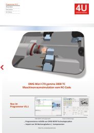
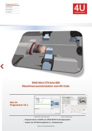
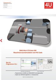
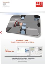
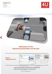
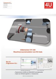
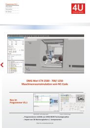
This is a multi-channel programming system for turning / milling machines with 3D machine room simulation. ● You create NC programs on the basis of an NC editor with machine macros and an integrated 2.5D CAD / CAM system. ● Templates are stored for different types of processing (bar / chuck ...). ● Program structures are generated automatically. ● The 3D machine space simulation shows the real machining process simultaneously. ● The actual implementation of the NC program is simulated. ● In the event of a collision, the relevant machine components and the associated NC blocks are displayed. What are the extensions of the V5.1 programmer? ● Project history and additional windows for further machine conditions ● Main and subprogram names are displayed in the simulation ● 3D blank (prismatic, rotationally symmetrical) is to be read in the STL format into the simulation ● The current workpiece is to be generated from the simulation as a 3D blank in the STL format ● Gaps can be measured in three dimensions ● NC block run times can be displayed as an EXCEL table
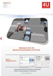
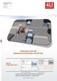
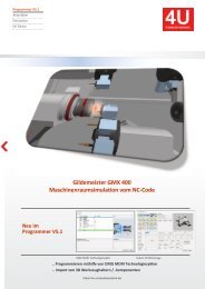
This is a multi-channel programming system for turning / milling machines with 3D machine room simulation.
● You create NC programs on the basis of an NC editor with machine macros and an integrated 2.5D CAD / CAM system.
● Templates are stored for different types of processing (bar / chuck ...).
● Program structures are generated automatically.
● The 3D machine space simulation shows the real machining process simultaneously.
● The actual implementation of the NC program is simulated.
● In the event of a collision, the relevant machine components and the associated NC blocks are displayed.
What are the extensions of the V5.1 programmer?
● Project history and additional windows for further machine conditions
● Main and subprogram names are displayed in the simulation
● 3D blank (prismatic, rotationally symmetrical) is to be read in the STL format into the simulation
● The current workpiece is to be generated from the simulation as a 3D blank in the STL format
● Gaps can be measured in three dimensions
● NC block run times can be displayed as an EXCEL table
You also want an ePaper? Increase the reach of your titles
YUMPU automatically turns print PDFs into web optimized ePapers that Google loves.
www.dmgmori.com
Turning technology
DMG Programmer 3D Turning V5
Programming
Training – The decisive know-how advantage
Training Manual
CONTROL
DMG Programmer V5
A-D821UK-1
Programmer 3D Turning V5
Programming and Operation
DMG MORI Academy GmbH
Gildemeisterstraße 60, D-33689 Bielefeld, Phone: +49 (0) 52 05 / 74 - 25 01,
Fax: +49 (0) 52 05 / 74 - 25 02, training@dmgmori.com, www.dmgmori.com
Disclaimer of warranty:
The information in this document has been compiled to the best of our knowledge.
However, we do not assume any responsibility for possible errors and consequential damage.
© 2020 DMG MORI Academy GmbH, Bielefeld
All rights reserved, including photocopies, filming, reproduction through image and sound carrier of any kind and
partial copies. According to the copyright law, it is prohibited to reproduce copyrighted works or part of them, even
for teaching or training purposes, except after consent from the publisher and, if applicable, against payment of a
fee for the use of foreign intellectual property. According to the copyright law, "those who reproduce a work without
the beneficiary's consent in cases other than those legally allowed" will be penalised with a prison term of up to one
year or with a money fine.
2
Dear customer!
Quality is our program.
We guarantee a high training standard by constantly optimising the course structures and regularly updating the
documents used for teaching.
The present teaching document has been designed to complement the machine's operating instructions and the
programming instructions of the control unit manufacturer. It does not and cannot replace them!
This document was didactically-methodically elaborated by the DMG MORI Academy. Its contents are oriented
towards your requirements, so that you hold in your hands an accompanying working tool during the course with
us and later on in your job.
In order to save what you have learned, write down your own notes on the margins provided for that purpose. This
will provide you with a useful way to brush up your knowledge.
We hope you are satisfied with our course and wish you the best possible success on your job.
Bielefeld, February 2020
3
Table of Contents
1 Table of Contents
1 DMG Programmer 3D Turning 8
1.1 Basic menu 9
1.2 Program management 10
1.3 New project 10
1.3.1 Defining a new project 11
1.3.2 Entering setting data 12
1.4 Defining operations 16
1.5 Defining a tool 17
1.5.1 Defining a new tool 18
1.6 Executing a tool change sequence 20
2 Simulation 26
2.1 Simulation toolbar 27
2.2 Zooming, rotating and moving using the mouse buttons 28
2.3 Simulation settings 29
3 Operation plan manager 32
4 CAD/CAM operations 36
4.1 Plane definition 36
4.2 Computer-aided design (CAD) 37
4.2.1 Setting the intersection snap function 38
4.2.2 Creating a new contour 38
4.2.3 Form elements and undercuts 39
4.2.4 Deleting elements 40
4.3 Generate operations in CAM 41
4.3.1 2D simulation 45
4.3.2 3D simulation 46
4.3.3 Generating an NC code 46
4.4 Turning cycles 48
4.4.1 Hiding elements 50
4.5 Operation on counter spindle 51
4.5.1 Generating the contour for counter spindle 52
4.5.2 Construction lines 53
4.6 Recesses 55
4.7 Generating an operation in channel 1 with B axis 57
4.7.1 Recess machining 58
4.8 Thread definition 59
4.9 Milling operation 61
4.9.1 Chamfering face contours 66
4.10 Face drilling 68
4.11 Milling using mechanical Y axis 70
4.12 Pocket milling using the CAM function 73
4.13 Y-axis machining – direct programming on turret machines (recess) 76
4.13.1 Y-axis machining – programming on turret machines using CAD/CAM (circular pocket) 79
4
Table of Contents
4.14 Cylindrical interpolation 84
4.14.1 Groove without macro 87
5 Machining with tailstock on the 4A TWIN machine model 92
5.1 Case 1 Machining on long zero point 92
5.2 Case 2 Short zero point 96
6 4-axis machining 100
7 Defining the raw part 108
7.1 Creation of the raw part in the CAD/CAM module 111
7.2 Reading in the raw part as STL 113
7.2.1 Loading of the STL file as raw part 114
9 G codes 124
9.1 Syntax explanation 124
9.2 High-level language and G codes relating to Programmer 125
9.2.1 Commands not supported (examples) 127
5
6
B
78
E
30°
F
36
32
0
1
45
57
14
25
20
M 42
32
31
40
18
R5
2
28
0
3
B
4
E
F
1 2 3
4
A
51,8
100±0,05
72,1
76,9
94,5
A
22,5°
DIN 76 - A
1,6x45°
2x45°
18 -0 ,05
- 0,01
x1,5
70 ±0,05
R 2,5
C
6± 0,05
C
6
2
D
48H7
D
167°
DIN ISO 13715
DMG-TA
36,5±0,02
+0,4 -0,4 Allgemeintoleranz ISO 2768-m
Verantwortl. Abt. Technische Referenz Erstellt durch Genehmigt von
DMG-TA
Dokumentenart
Fertigungszeichnung
Rohmaterial : Rd 80x102
Alle Kanten gebrochen
Nicht bemaßte Radien/ Fasen 1 mm
Dokumentenstatus
freigegeben
Titel, zusätzlicher Titel Material
Änd. Ausgabedatum
Übung 4
M 1:1
EN AW-Al Cu 4 PB Mg
Spr.
de
Blatt
1
1
Chapter
3D Preparation programs
1 | DMG Programmer 3D Turning
Memo
1 DMG Programmer 3D Turning
This training document shall be used in conjunction with a training course provided by
DMG MORI Academy only and makes no claim to be complete.
It describes the complete step-by-step programming procedure from the entry of a
new workpiece to the finished machining program.
To make yourself familiar with the steps described, we recommend reading the individual
topics page by page and then repeating them by hands-on experience at Programmer
3D.
8
A-D821UK-1_200420
1 | DMG Programmer 3D Turning
1.1 Basic menu
Most operations can be executed by means of appropriate icons. In addition, menu
sequences are available (e.g. FILE, BASIC MENU instead of the respective icon).
Memo
DMG Programmer 3D Turning
1
9
Projects - e.g. definition of a new workpiece
Waitmarks manager (for 4-axis machining only)
ISO converter - conversion of the programmed sequences into Siemens high-level
language
Simulation - 3D simulation with collision monitoring
Tool setting sheet - management of the tools for the current (selected) workpiece
Workpiece settings - zero points, chuck data, raw parts, etc.
Operation plan manager - definition of a new tool based on the Gildemeister work
plan
Macros catalogue
Tools catalogue - all tools stored are listed here. Program management
A-D821UK-1_200420
9
1 | DMG Programmer 3D Turning
Memo
1.2 Program management
Programmer automatically opens an overview window that comprises 4 individual windows.
On the left, you will find a list of all workpieces and of the installed machines.
In Channel 1 and Channel 2, the operations (=programs) are displayed while the part
of the program that has just been clicked in Channel 1 or Channel 2 is shown on the
right. Here, the NC code can be edited directly.
1.3 New project
In the following sections, you can learn step by step how to define and generate
a project with its machining processes.
To make the procedure valid for all machines, the workpiece of this first project is
manufactured at spindle 4 with channel 2 only.
As an example, the first exercise from the Annex is used.
10
A-D821UK-1_200420
1 | DMG Programmer 3D Turning
1.3.1 Defining a new project
To define a new project, select the tab "Projects" from the basic menu.
Then select the appropriate machine and open the pop-up menu using
the right mouse button.
Memo
1
11
DMG Programmer 3D Turning
The following window appears for the entry of further data.
Here, you can enter global project information.
The minimum input requirements are the project name and the model. In this dialogue,
a model can only be entered once.
After the data have been entered in the required fields, close the window using
"OK".
A-D821UK-1_200420
11
1 | DMG Programmer 3D Turning
Memo
1.3.2 Entering setting data
Next, you should specify the setting data such as fixtures, workpiece,
jaws and transfer parameters. To do so, click the icon for entry of
workpiece settings.
All the parameters being relevant for the workpiece are transferred into the loading
program for variables via the workpiece settings function. Moreover, the clamping
and workpiece data are entered for 3D simulation. In detail, this refers to the following
data:
Base body of the
clamping device
Clamping elements
such as jaws
Define workpiece or
read in STL file
RG738 = raw part diameter
RG725 = finished part length
Minimum Ø = hole diameter
Add-on Z - Rear = allowance on left side (SP3)
Add-on Z - Front = face allowance on right side (SP4)
Send to other spindle
Delete
Save data
Design your own chuck
Accept the settings by pressing OK.
12
A-D821UK-1_200420
1 | DMG Programmer 3D Turning
If data shall be entered for all the spindles, you can select the appropriate tab to
change over to the desired spindle. Similar data are entered for the spindles 3 and 4.
Memo
1
13
Tabs for change-over
Base body of the
clamping device
DMG Programmer 3D Turning
Clamping elements
such as jaws
Some parameters may not apply and others may be added depending on the machine
options.
If you want to define one of the fixtures or the raw part as a contour, this can be done
as well here in the setting manager (design your own chuck). You still need to set the
parameters for zero-point definition and transfer position in the "Parameter" tab.
A-D821UK-1_200420
13
1 | DMG Programmer 3D Turning
Memo
RG720 = dimension between front edge of jaw / collet and workpice zero point
RG712 = cut-off width + allowance
RG724 = jaw overtravel length sp.3
RG713 = machining compartment length sp4. to sp.3
14
A-D821UK-1_200420
1 | DMG Programmer 3D Turning
Memo
1
15
DMG Programmer 3D Turning
The appropriate parameters can be taken from the Help screen.
After the completion of setting data input, the sequence of operations can be defined.
Make sure the two channels contain the same number of machining processes. Operations
that do not contain machining processes are designated as NOP-OP and must
be defined accordingly.
A-D821UK-1_200420
15
1 | DMG Programmer 3D Turning
Memo
1.4 Defining operations
Each operation is stored in a separate program. In general, the first operation is defined
after the start program.
To do so, select the start program and open the pull-down menu by clicking the right
mouse button.
In this menu, select "New Operation".
The following screen form appears.
Depending on the machine type,
it is important to set the correct
operation templates
and planes.
RG720, RG722 (short part)
RG730 (X3 top)
RG823 (Z3 front)
The same applies when working
with the counter spindle and with
the tailstock.
Assign a name of your choice to the operation, e.g. Schruppen_sp4.
Check any further fields and adjust their contents if necessary.
16
A-D821UK-1_200420
1 | DMG Programmer 3D Turning
1.5 Defining a tool
The next input window requests a tool for the new operation.
Select the appropriate tool from the tool management list or define a new one.
Memo
1
17
DMG Programmer 3D Turning
Copy
tool
Delete tool
Import tool from
catalogue
Save selected tool
in file
Read in selected tool
from file
3D display
New
tool
Edit
properties
Move
tool
Tool
export
Tool export
Export all tools into
Excel file
channel/spindle specification
A-D821UK-1_200420
17
1 | DMG Programmer 3D Turning
Memo
1.5.1 Defining a new tool
Upon clicking "New Tool", the selection screen shown below appears.
3 4
1
2
5
6
Item
Description
1 Tool type selection
2 Cutting edge geometry
3 Prepare kit or use available kits
4
3D view of the selected tool. By selecting one of the radio buttons Cutter, Holder
or Clamp below the view, you can display only the view concerned. All selected =
entire list
5 Input of cutting edge geometry data
6 Input of tool parameter data
When all the parameters have been set, the tool is defined with OK. The newly
defined tool must now be selected. (Mark and select with OK.)
18
A-D821UK-1_200420
1 | DMG Programmer 3D Turning
Finally, the tool offset can be defined under "Tool correction".
Memo
1
19
DMG Programmer 3D Turning
A complete operation always consists of machining process and tool that are combined
to nodes which can be expanded using the "+".
Accept the entries by pressing OK.
A-D821UK-1_200420
19
1 | DMG Programmer 3D Turning
Memo
1.6 Executing a tool change sequence
The new operation has now been defined with the appropriate tool.
In the NC Code field, place the mouse pointer to the position where the tool
change process shall be inserted. (Here: block 11 - red cursor)
Select the tab "Common Macros".
Here, you will find common macros for turning and drilling operations as well as for
the insertion of tool changing processes.
Select the "Tool change" macro.
The following tool change screen appears.
20
A-D821UK-1_200420
1 | DMG Programmer 3D Turning
You can confirm the subsequent queries using the ENTER or TAB key.
Memo
1
21
DMG Programmer 3D Turning
With each confirmation with the Enter key, the appropriate program line (marked in
blue) is inserted in the lower field.
Finally, click "FINAL" to display the result which is inserted in the NC code by pressing
"OK".
A-D821UK-1_200420
21
1 | DMG Programmer 3D Turning
Memo
The NC code is inserted at the position selected beforehand.
Manual entry in NC editor
In the NC editor, data can also be entered manually. This e.g. may be helpful to face a
workpiece at high speed. To do so, go to the NC editor, select the desired position and
enter the NC code.
Example: Inserting a cutting cycle
Go to the Macros area.
Select the subitem Turn Cycles.
Select the cutting cycle CYCLE95.
The screen form for parameter definition appears.
22
A-D821UK-1_200420
1 | DMG Programmer 3D Turning
Memo
1
23
DMG Programmer 3D Turning
Define the values for the cycle and go to the next parameter using the ENTER key.
When the "FINAL" point has been reached, the cycle is inserted in the editor by
confirming with "Yes".
The NC code will then look as follows:
Finally, the contour must be defined.
Place the cursor at the positions between Begin and End labels and press the
common macro "Countour Definition".
A-D821UK-1_200420
23
1 | DMG Programmer 3D Turning
Memo
The displayed NC code is transferred to the editor and inserted between the Begin
and End labels by pressing OK.
The Contour elements Point, Line or Lines at an angle are used to define the contour.
At the end, the entire program can be renumbered using the "Numbering of lines"
macro.
24
A-D821UK-1_200420
2
Chapter
Simulation
2 | Simulation
Memo
2 Simulation
Select the Simulation item in the basic menu.
Simulation is loaded upon confirmation with "OK".
1
2
3
4
5
Item
Description
1 Toolbar used to control simulation
2 Status display per channel
3 Main simulation window
4 Program run display
26
A-D821UK-1_200420
2 | Simulation
2.1 Simulation toolbar
Memo
2
27
Single block F6
Fast forward F8
Reload Crl+R
Focus on collision
(active only in case of
collision)
Simulation
Start F7
Break F5
Focus on workpiece
Focus on machine
Feedrate and rapid
speed setting
Change detail degree
Measurement ON/OFF
Change view
Set contour
mode
Hiding mode ON/OFF
Half section ON/OFF
Insert
new view
A-D821UK-1_200420
27
2 | Simulation
Memo
2.2 Zooming, rotating and moving using the mouse buttons
Keep the left mouse button pressed and move the mouse in circles to the left:
rotating the simulation to the left.
Keep the left mouse button pressed and move the mouse in circles to the right:
rotating the simulation to the right.
Keep the right mouse button pressed (same function as the scroll wheel) and move
the mouse upwards: zooming in simulation.
Move the mouse down: zooming out simulation.
Scroll wheel: turn upwards -> zooming in simulation
Turn downwards -> zooming out simulation
Keep pressed -> Rotating around the machine axis to the right
or left.
Positioning of the mouse pointer and left double-click will move the point clicked towards
the simulation centre.
Keep both mouse buttons pressed: moving the machine to the right or left or up or
down.
28
A-D821UK-1_200420
2 | Simulation
2.3 Simulation settings
Memo
Simulation settings are stored related to the project When clicking the "Sensitivity"
item, a drop-down menu appears in which User-defined can be selected. Parameters
can now be enabled or disabled if desired.
2
29
Simulation
A-D821UK-1_200420
29
2 | Simulation
Memo
30
A-D821UK-1_200420
3
Chapter
Operation plan
manager
3 | Operation plan manager
Memo
3 Operation plan manager
The Operation plan manager is used to schedule operations and assign them to channel and
spindle.
The procedure is the same as described above for manual generation of operations -
with graphical channel and spindle display.
Procedure:
New workpiece
Workpiece settings
Operation plan manager
Creating operations
Create a new operation using "New".
Confirm with "Yes".
Define the channel.
As already described in the previous sections,
define the required settings. (Basic settings
and tool) Optionally, select NOP_OP for an
empty operation at this spindle/in this channel.
32
A-D821UK-1_200420
3 | Operation plan manager
Memo
3
33
The new operation is now defined in the operation plan designer. The synchronous
operation can be moved using the drag&drop function. By clicking the Edit icon, it can
be defined.
Operation plan manager
Define the synchronous operation by clicking the "Edit" icon.
You will be automatically enquired whether you want to define an empty operation. If
your answer is No, you will return to the known basic settings menu.
Icon
Description
Insert a new operation after an operation already programmed.
Delete operation
Insert a new line above the selected one with a simultaneous NOP_OP synchronous
operation.
Edit
A-D821UK-1_200420
33
3 | Operation plan manager
Memo
Define the entire workpiece operation and finally press "OK". The operation plan manager
is solely used to define the sequence of operations. Then, the appropriate cycles
and parameters for the machining process must be created.
Define the machining processes as described in the previous chapter.
34
A-D821UK-1_200420
4
Chapter
CAD / CAM
4 | CAD/CAM operations
Memo
4 CAD/CAM operations
4.1 Plane definition
The sequence of operations has been defined (through operation plan manager or
manually).
Open the first machining operation by double-click.
Select the geometry item.
A window appears in which the machining plane "Create new worlds" can be selected.
Operation
Rotation
Front
C/Y Surface
B/Y Axis
Y Front
Plane
Plane of rotation (G18)
Face milling, creates a TRANSMIT_S4 or S3 (G17)
Cylindrical interpolation, creates a TRACYL_S4 or S3 (G19)
B axis (G17)
Mechanical Y axis (G17)
36
A-D821UK-1_200420
4 | CAD/CAM operations
4.2 Computer-aided design (CAD)
Memo
For a turning contour, select the Rotation field. The following design screen appears.
1
2
3
4
37
CAD/CAM operations
Item
Description
1 Design toolbar
2 Design and machining sequence
3 Drawing plane
Icons
Description
Geometry generation:
Generation of auxiliary designs by means of
• Point definition
• Line definition
• Circle definition
Generate a contour:
• New contours, contour expansion, holes
• Macros: Undercut, recess, groove, circle and rectangle
• Point, line, arc, chamfers, radii
• Join with line, join with arc, close
Change a contour:
• Chamfers/radii, delete element, change radii, elongate
• Factor, offset, shift start / end, join/separate contour
• Working direction, soft on contour, attribute,
restore geometry elements
Edit:
Contours: Copy, mirror, shift, set zero point, rotate, delete
Measurement:
Contours: Measure distance, display element, measure
perimeter
A-D821UK-1_200420
37
4 | CAD/CAM operations
Memo
4.2.1 Setting the intersection snap function
Select the design surface by clicking the right mouse button. You can now select the
desired intersection snap options. This is always possible during the design process.
4.2.2 Creating a new contour
Select Contour new.
There are several ways of generating a contour.
By means of direct entry of the dimensions using F9.
By means of the Line contour definition.
Use Point definition to define the start point first
and then define the next contour point.
With the "Linie" contour definition, you can promptly verify the entered values since
they are immediately displayed. (green)
38
A-D821UK-1_200420
4 | CAD/CAM operations
Memo
4
39
CAD/CAM operations
4.2.3 Form elements and undercuts
Form elements such as radii or chamfers are inserted once the actual contour has
been generated.
Press the Chamfer/Radius softkey and select the contour.
Then select the adjacent elements.
The information bar at the bottom of the screen contains accurate instructions about
how to execute the selected operation.
Press the Undercut softkey and select the shape.
Select the appropriate corner.
A window for data entry appears.
A-D821UK-1_200420
39
4 | CAD/CAM operations
Memo
Define the parameters and press
"OK".
4.2.4 Deleting elements
There are two possibilities to delete programmed elements:
Delete element
Delete it using the "Eraser".
Procedure
Select the contour.
Select the element to be deleted.
To delete the entire contour, select the eraser. Select the contour and confirm with
Enter. The contour is deleted.
40
A-D821UK-1_200420
4 | CAD/CAM operations
4.3 Generate operations in CAM
Memo
After the contour has been generated, the machining process must be defined
in the CAM area.
To do so, select the CAM tab.
The following screen appears.
4
41
CAD/CAM operations
Select the "CAM" item in the toolbar.
The screen form for raw-part definition appears.
If all the parameters have been correctly defined in the machine setting sheet beforehand,
they are automatically entered in the screen form for raw-part definition and
can be accepted.
A-D821UK-1_200420
41
4 | CAD/CAM operations
Memo
The defined raw part is laid over the programmed contour and highlighted by hatching.
Select "New Operation".
Select New Operation and assign
a name.
Confirm the selection with OK.
42
A-D821UK-1_200420
4 | CAD/CAM operations
A tool selection screen for the operation defined in the operation manager (here: drilling)
appears.
Memo
4
43
CAD/CAM operations
Select the appropriate tool and confirm the selection with "OK".
A pop-up menu appears. Here, the tool change process must be selected.
Confirm the selection with OK.
The tool change menu, that has already been described above, appears.
The tool change process is now displayed under the CAM operation "Drilling".
A-D821UK-1_200420
43
4 | CAD/CAM operations
Memo
Since the toolbar depends on the currently selected operation, only the cycles shown
here are enabled.
Drilling cycle
Approach/retraction cycles
Loading a
defined macro
Free movement and storage of the paths
Select a drilling cycle. The menu shown here appears:
Define the parameters and confirm the entry
with "OK". The cycle will also appear in the
tree structure below the defined tool.
The NC code function can be used to
show the selected cycle as NC code in
the side menu.
If you select the topmost operation, the entire
NC code for this operation is displayed.
44
A-D821UK-1_200420
4 | CAD/CAM operations
The 2D or 3D simulation function can be used to simulate any cycles already programmed
or the selected operation.
Memo
To do so, press 2D or 3D Simulation. The screen shown here
appears.
4
45
4.3.1 2D simulation
CAD/CAM operations
4
1
2 3
Item
Description
1 Simulation window
2 Start / Stop, Forward / Backward
3 Speed regulation
4 NC code moving along. The current block is highlighted (green).
A-D821UK-1_200420
45
4 | CAD/CAM operations
Memo
4.3.2 3D simulation
2
1
3
Item
Description
1 Simulation window
2 Select view X, Y, Z, Coordinate plane ON / OFF as well as various views
3 Start / Stop, Forward / Backward, speed regulation
4.3.3 Generating an NC code
Finally, the NC code must be generated. To do so, press the softkey for NC
code generation. A preview window containing the generated code appears.
If the NC code is ok, it can be entered
into the machining subroutine by pressing
the "Insert" button.
46
A-D821UK-1_200420
4 | CAD/CAM operations
Memo
4
47
CAD/CAM operations
The operation can now be loaded into machine
simulation or displayed as an ISO file
Creating the subsequent operation:
Call the main screen and select the next operation.
Click Geometry and select the previous operation.
Upon confirmation, you will return to the CAM screen.
A-D821UK-1_200420
47
4 | CAD/CAM operations
Memo
4.4 Turning cycles
Once again, tool-dependent cycles are available. In this case,
you can select from cutting cycles for face machining and longitudinal machining.
Select Face Cut and enter the parameters in the screen form.
For roughing, start and end points on the contour must be defined first.
The selected start and end points are marked with a yellow circle. The selected contour
in between is marked in yellow as shown in the picture below. This is the selected
roughing contour.
After the selection of the end point, the parameter definition menu shown below
appears automatically.
48
A-D821UK-1_200420
4 | CAD/CAM operations
Memo
Define the parameters and confirm the entry with "OK".
If the cycle shall be defined as Machine Cycle
(CYCLE95 in this example), check the appropriate check
box in this screen form.
4
49
When all the values have been entered, confirm the entry
with "OK". The machine cycle screen form appears.
CAD/CAM operations
You can exit the menu with "Ja" and then simulate the new operation just created.
Finally, generate the NC code. Repeat this procedure for each operation that follows.
A-D821UK-1_200420
49
4 | CAD/CAM operations
Memo
4.4.1 Hiding elements
It may become necessary to hide contour elements for a specific operation. The "Linear"
function is provided for this purpose.
Select the "Linear" option.
Call the context menu using the right mouse button and e.g. select
the "Intersection" function.
Snap the intersection.
Select the end point as the next element.
The contour to be hidden is displayed in yellow.
After the selection of the end point, the linear element just as the contour are displayed
in magenta.
Referring to the roughing cycle described above, the undercut is now hidden for the
roughing operation, i.e. undercuts are not realized.
Using "All Fade In, any hidden elements can be shown again. When
selecting a subsequent finishing cycle,
the elements that were hidden in the roughing cycle will be shown
again automatically.
50
A-D821UK-1_200420
4 | CAD/CAM operations
4.5 Operation on counter spindle
Memo
First, a tool must be defined for the B axis. See section 1.5.1.
The tool is defined in the same way as turret tools. That's why only the properties of
B-axis tools are described here.
4
51
CAD/CAM operations
Function
Tool T
Tool name
Tool offset
Milling 1 / Turning 2
Tool position
B and C
Description
Opening the tool parameters
Can be defined under the tool parameters
1-4, depending on the defined cutting edge
Definition of whether the tool is clamped (2) or not (1 = milling operation)
Definition of the B and C axis angles of the tool. Using the "Open" button
, a help window appears in which the entered data are visualized
in the form of a graph.
A-D821UK-1_200420
51
4 | CAD/CAM operations
Memo
4.5.1 Generating the contour for counter spindle
Under "Geometry", select spindle 3 and confirm the selection with "OK".
The choice of machining geometries is displayed.
Here, select the "Rotation" item and confirm the selection with "OK".
The design window for contour definition appears.
Define the desired contour using construction lines in accordance with exercise 2
in the Annex.
52
A-D821UK-1_200420
4 | CAD/CAM operations
4.5.2 Construction lines
Memo
Construction lines are used to define diameters and Z end points with the aid of vertical
and horizontal lines in order to generate intersections which are used later to define
the contour.
The function can be called via "Line" or F9.
4
53
CAD/CAM operations
In the sub-menu of the "Line" function (click the small black arrow), the functions
shown can be called directly.
Once all the construction lines have been defined, describe the contour
geometry using "New contour". First, however, select "Intersection" in the context
menu of the right mouse button.
A-D821UK-1_200420
53
4 | CAD/CAM operations
Memo
Confirm the entries by pressing OK. The defined
recess can then be picked up by mouse click and positioned
using F9 (direct specification of dimensions).
Use the intersections to define the contour. Furthermore, the direct specification of
dimensions can be enabled with F9.
At the end, define the form elements according to the drawing by means of the
"Chamfer/Radius" function.
54
A-D821UK-1_200420
4 | CAD/CAM operations
4.6 Recesses
Memo
Using the "Recess" function, you can define the recess parameters in the
called screen form.
4
55
CAD/CAM operations
The completed contour is as follows:
A-D821UK-1_200420
55
4 | CAD/CAM operations
Memo
The contour described should now be loaded into the CAM area.
Use "CAM" to load the contour into the CAM area.
Answer the enquiry "Rohteil aus bestehender Operation laden" with "Ja".
An overview of the operations already defined on the main spindle appears. Select
the last operation (Schruppen_Innen in this example) and confirm the selection
with "OK".
The operations already programmed are laid over the new contour and highlighted by
hatching.
56
A-D821UK-1_200420
4 | CAD/CAM operations
Memo
4
57
CAD/CAM operations
4.7 Generating an operation in channel 1 with B axis
Select "New Operation".
Insert a tool change process.
When the tool change has been executed, the window used to define cutting edge
position, machining direction as well as clearance angle and lead angle appears
automatically.
2
1
Item
Description
3
1 Cutting edge position
2 Machining direction
3 Setting angles
4
4 Help view
Define all the machining data for the counter spindle.
Hide the recess for roughing and finishing and the undercut for roughing.
A-D821UK-1_200420
57
4 | CAD/CAM operations
Memo
4.7.1 Recess machining
Insert a tool change process.
Define a new tool orientation.
Open "Recess".
The shown selection window appears.
Here, you can select how the recess tool shall recess referring to the defined cutting
edge.
Define the start and end points of the recess in the contour.
The screen form for parameter definition automatically appears.
58
A-D821UK-1_200420
4 | CAD/CAM operations
Memo
4
59
Define the contour extension mode here and
define the start and end points in the subsequent
step in the contour editor.
CAD/CAM operations
At the end, the screen form used to enter the entry and exit movements of the tool appears.
A-D821UK-1_200420
59
4 | CAD/CAM operations
Memo
4.8 Thread definition
Threads are solely defined in the editor.
Select the "Turn Cycle" macro under Common Macros. The sub-menu contains
the item Thread cutting (G97).
First, generate a tool change process.
Call the thread cutting cycle. The following screen form appears.
60
A-D821UK-1_200420
4 | CAD/CAM operations
4.9 Milling operation
Memo
Exercise 4 explains some of the usual milling operations.
Use a "New Operation" to select and define the selection dialog for the machining
plane.
4
61
CAD/CAM operations
After having entered all parameters, the ToolManager automatically appears. Here, you
can define a new milling cutter (D=20 mm) as shown in the figure.
A-D821UK-1_200420
61
4 | CAD/CAM operations
Memo
Accept the tool setting.
Define the
tool offset
under "Tool
correction"
and confirm
the entry
with "OK".
Go to the CAM module and define the machining plane.
The rectangle to be generated can be generated by means of the "Square" function.
However, it can also be designed with the aid of construction lines. Since a hexagon
remains to be generated later, the design approach shall be explained here.
Design the square as shown below.
62
A-D821UK-1_200420
4 | CAD/CAM operations
Define the square using the intersection snap function as already described above.
Memo
4
63
CAD/CAM operations
The arrow on the square specifies the machining direction. It thus defines whether
down-cut milling or up-cut milling shall be adopted, If down-cut milling is executed, as
is done in this example, it can be reverted with the "Workdirection" function.
A-D821UK-1_200420
63
4 | CAD/CAM operations
Memo
Go to the CAM module and define the machining plane.
Execute a tool change process.
Select the "Contour Milling" cycle.
Select the desired contour.
Define the start and end points. (They are congruent in our example.)
The screen form for parameter definition appears.
64
A-D821UK-1_200420
4 | CAD/CAM operations
Now define the approach and retraction movements. First, however, you should
select the contour extension method.
Memo
4
65
CAD/CAM operations
Now define the points on the contour.
The milling cycle can now be simulated.
Finally, generate the NC code.
A-D821UK-1_200420
65
4 | CAD/CAM operations
Memo
4.9.1 Chamfering face contours
Use a "New Operation" to select and define the selection dialog for the machining
plane.
Define an NC spot drill.
Enter the appropriate tool settings.
Go to CAM area.
Select the previous operation.
The square is loaded.
Call the design mode (F6).
Select the "Contour allowance" option and define the
machining side and the distance.
The offset is generated.
66
A-D821UK-1_200420
4 | CAD/CAM operations
Memo
4
67
CAD/CAM operations
Go to CAM area.
Generate a new operation.
Execute a tool change process.
Select the desired tool.
Select the the milling cycle.
Define the contour and enter the parameters as shown in the figure.
A-D821UK-1_200420
67
4 | CAD/CAM operations
Memo
Define the approach and retraction movements.
Now, the simulation can be executed.
Generate the NC code.
4.10 Face drilling
Use "New Operation" to select and define the selection dialog for the machining
plane.
Define a drill with D=8.5 mm.
Enter the appropriate tool settings.
Go to CAM area.
Insert a tool change process.
68
A-D821UK-1_200420
4 | CAD/CAM operations
Select the "Drilling Front C-Axis" macro under "Common Macros".
Memo
The following screen form appears; here, enter the data specified in the drawing.
4
69
CAD/CAM operations
Accept the entries.
The NC code is inserted in the editor.
A-D821UK-1_200420
69
4 | CAD/CAM operations
Memo
4.11 Milling using mechanical Y axis
Use "New Operation" to select and define the selection dialog for the machining
plane.
Define a mill with D=50 mm.
Enter the appropriate tool settings.
Call the editor.
Insert a tool change process.
Position the C axis at 90° (G0 C4=90 M412).
The shift must be programmed next.
Open the "Shift" subroutine and jump to a vacant position in the subroutine.
Use the macro "Commands for displacement" to insert a new
shift in the editor. The input menu shown below
appears.
70
A-D821UK-1_200420
4 | CAD/CAM operations
Memo
4
71
CAD/CAM operations
Assign a name to the shift and confirm the entries. Only the ATRAS and AROT
commands are inserted in the editor.
The shift values must be entered manually in the editor. When doing so, make sure that
"Z" is selected as the infeed axis.
Go to the surface milling operation.
Use the "Shift" macro -> "Shift choose" to call the shift, that has been defined
previously, in the editor.
A-D821UK-1_200420
71
4 | CAD/CAM operations
Memo
Call the already programmed shifts in the first input field by pressing the Return or
Enter key.
Confirm the entries by pressing "OK".
The shift is inserted in the editor.
Finally, the traverse movement must be programmed.
72
A-D821UK-1_200420
4 | CAD/CAM operations
4.12 Pocket milling using the CAM function
Memo
Use "New Operation" to select and define the selection dialog for the machining
plane.
Define an 8 mm mill.
Enter the appropriate tool settings.
Go to the CAM area.
Select "None" in the "Previous operation" dialog.
Select B-Axis in the "Create new worlds" dialog.
4
73
CAD/CAM operations
Assign a name to the operation. It can be changed at will, e.g. to Pocket.
In the design window, select "Circle" and enter the circle diameter.
Select the intersection function and arrange the circle with its centre at the intersection
of the coordinate axes (0/0).
A-D821UK-1_200420
73
4 | CAD/CAM operations
Memo
Since the pocket milling function is not yet available at the moment, the contour milling
cycle with allowance must be used and programmed repeatedly.
Select "New Operation" in the CAM window.
Tool selection.
Execute the tool change process.
Select the contour milling cycle.
Select the contour and define the start and end points.
Define the parameters as shown below.
74
A-D821UK-1_200420
4 | CAD/CAM operations
In the last step, set the allowance to "0" (under "Overmeasure").
Check the check box "Insert last values".
Memo
4
75
CAD/CAM operations
Apply the data and confirm the "Clamp C axis" enquiry.
Finally, simulate the operation and generate the NC code.
Then manually enter the C-axis position into the editor and define the shift.
A-D821UK-1_200420
75
4 | CAD/CAM operations
Memo
4.13 Y-axis machining – direct programming on
turret machines (recess)
Select New Operation and set the G19 machining plane (Driven surface).
Apply the entries by pressing OK.
76
A-D821UK-1_200420
4 | CAD/CAM operations
Define a new tool for lateral surface machining. Cutter head D=30.
Memo
4
77
CAD/CAM operations
Select the operation and confirm the enquiry regarding tool change by pressing
Yes.
A-D821UK-1_200420
77
4 | CAD/CAM operations
Memo
The actual machining process is now inserted below the technology. Make sure the Y
axis is returned to 0 after the machining process; otherwise, the X axis would reach the
software limit switch when it is moved to the TCP. Moreover, the C axis should be positioned
and additionally be clamped.
78
A-D821UK-1_200420
4 | CAD/CAM operations
4.13.1 Y-axis machining – programming on turret machines using CAD/CAM
(circular pocket)
Memo
4
79
CAD/CAM operations
Select New Operation and set the G19 machining plane (Driven surface).
Apply the entries by pressing OK.
A-D821UK-1_200420
79
4 | CAD/CAM operations
Memo
Define a new tool for lateral surface machining. End mill D=8.
Select the operation and answer the enquiry regarding tool change with No.
Go to the geometry settings function.
Create a new world with the following settings: Y-Surface, C=180, Dist. from centre=20
and Depth plane (absolute)=15.
Confirm both enquiry dialogs by pressing OK. The CAD/CAM view with the Surface
plane appears.
80
A-D821UK-1_200420
4 | CAD/CAM operations
Memo
4
81
CAD/CAM operations
1
1 = Coordinate system for Y surface machining
Select the circle macro in the design window.
Enter the pocket radius.
Position the circular pocket with F9.
Go to CAM area.
Define the raw part.
Select tool change as new operation.
Mill the pocket.
Select the pocket and confirm it with Enter.
A-D821UK-1_200420
81
4 | CAD/CAM operations
Memo
Define the pocked based on the drawing.
Confirm the 4. Axis Clamp enquiry with OK.
Finish the procedure with a simulation with the entered data.
82
A-D821UK-1_200420
4 | CAD/CAM operations
Memo
4
83
CAD/CAM operations
Generate the NC code.
Insert the NC code in the machining process.
Go to 3D Simulation and check the programming as well as the
traversing paths.
A-D821UK-1_200420
83
4 | CAD/CAM operations
Memo
4.14 Cylindrical interpolation
Select New Operation and set the G19 machining plane (Driven surface).
Apply the selection with OK.
Define a new tool for lateral surface machining. End mill D=8.
84
A-D821UK-1_200420
4 | CAD/CAM operations
Memo
4
85
CAD/CAM operations
Select the operation and answer the enquiry regarding tool change with No.
Go to the geometry settings function.
Create a new world with the following settings: C Surface D=60.
Confirm both enquiry dialogs by pressing OK. The CAD/CAM view with the Surface
A-D821UK-1_200420
85
4 | CAD/CAM operations
Memo
1
plane appears.
1 = Coordinate system for C surface machining
Select "Interactive" in the "Line" menu.
Define the groove insertion point with F9.
Use the longitudinal groove to define the groove based on
the drawing.
Define the groove type.
Position the groove centre by means of the "Intersection" snap mode.
86
A-D821UK-1_200420
4 | CAD/CAM operations
Memo
4
87
CAD/CAM operations
4.14.1 Groove without macro
If you want to generate a groove without macro, proceed as follows:
Define the groove insertion point, parallel lines and auxiliary circles.
A-D821UK-1_200420
87
4 | CAD/CAM operations
Memo
Define a new contour with the right mouse button and define the intersection as the start point.
Change over to the object mode.
Select contour elements.
Go to CAM area.
Define the raw part.
Select tool change as new operation.
Mill the groove.
Select the groove.
Define the insertion point (upper or lower centre point).
88
A-D821UK-1_200420
4 | CAD/CAM operations
Memo
4
89
CAD/CAM operations
Enter the cycle data based on the drawing.
Finish the procedure with a simulation with the entered data.
Generate the NC code.
Insert the NC code in the machining process.
Go to 3D Simulation and check the programming as well as the
traversing paths.
A-D821UK-1_200420
89
3 | CAD/CAM operations
Memo
90
A-D821UK-1_200420
5
Chapter
Machining with
tailstock 4A TWIN
4 | Machining with tailstock on the 4A TWIN machine model
Memo
5 Machining with tailstock on the 4A TWIN machine model
5.1 Case 1 Machining on long zero point
This section describes the generation of standard machining processes with tailstock
centre sleeve in Programmer, provided that there is still no appropriate template program.
In the first variant, we will show a structure without structure at the part advanced.
First, define a new project.
Select the model.
First, choose an appropriate model from the TEMPLATE folder. When doing so, please
observe bar loader and remnant disposal.
In addition to the usual set-up parameters, a tailstock centre and other tailstock-related
data must be input.
92
A-D821UK-1_200420
4 | Machining with tailstock on the 4A TWIN machine model
Call the workpiece settings and go to the tailstock settings.
Memo
The structure that is now available must be supplemented by the standard centre sleeve
machining processes. In general, these processes are:
Channel1: - Pre-positioning of X3 and Z3
- Machining at Sp3 or Sp4.
Channel2: - Centring at Sp4
- Centre sleeve advance at Sp4
- Machining with tailstock centre at Sp4
- Centre sleeve retraction at Sp4
RG771 = workpiece-specic centre sleeve stroke
RG772 = tolerance window
RG774 = depth of penetration of centre sleeve
into the workpiece
RG771 = feed distance
5
93
Machining with tailstock on the 4A TWIN machine model
The first machining process in
channel 1 moves the X3 axis upwards
and advances the Z3 axis
to the supporting position.
Make sure RG730 and the correct
template program are called.
A-D821UK-1_200420
93
4 | Machining with tailstock on the 4A TWIN machine model
Memo
Now, program the following machining operations in the channel.
Then advance the centre sleeve using a new template.
The first actual machining process can now be executed at the main spindle. In our example,
this is a simple roughing process. For this process, program Longitudinal Machining.
As a last standard machining process, the centre sleeve is retracted. For this process
as well, there is an appropriate operation template. Once again, the subsequent tool
selection is suppressed.
The finished operation plan for channel 2 will be as follows:
94
A-D821UK-1_200420
4 | Machining with tailstock on the 4A TWIN machine model
Memo
5
95
Machining with tailstock on the 4A TWIN machine model
Finish the procedure with a simulation of all steps.
A-D821UK-1_200420
95
4 | Machining with tailstock on the 4A TWIN machine model
Memo
The generated program can be saved as a template in the program manager. To do so,
click the program with the right mouse button and select "Create template".
The new template is then automatically saved in the Templates field.
5.2 Case 2 Short zero point
In this section, we will present a bar machining process using centre sleeve and centring
on a short part that has not been advanced yet. Topics such as positioning of X3 / Z3 or
advance and retraction of centre sleeve will not be discussed in further detail here. The
template previously created will be used as a basis for the new program.
Define a new project to be able to perform the changes; here, select the "Langer
Nullpunkt" template.
In V-INIT, define the calculation of the short zero point.
Select the short zero point (RG722) for facing and centring in the existing program.
96
A-D821UK-1_200420
4 | Machining with tailstock on the 4A TWIN machine model
Memo
5
97
Define a new operation to advance the material.
Confirm the entry with OK and select the bar stop as the tool.
Machining with tailstock on the 4A TWIN machine model
Delete the marked standard lines from the defined program.
A-D821UK-1_200420
97
4 | Machining with tailstock on the 4A TWIN machine model
Memo
Cut the marked contents from "Material in Hauptspindel" by pressing Ctrl+X and
paste them in "Material_Vorschieben".
Now, add the following NC blocks to the operation "Material in Hauptspindel"´.
Simulate the program.
Finish the procedure by saving the program as a template.
98
A-D821UK-1_200420
6
Chapter
4-axis
machining
4 | 4-axis machining
Memo
6 4-axis machining
The machining at the main spindle using slide 1 for face and longitudinal roughing operations
and slide 2 for drilling operations serves as an example.
Make sure machining is only possible with the spindle rotating in one direction!
100
A-D821UK-1_200420
4 | 4-axis machining
Tool selection for channel1:
When using a right-hand cutting drill for channel 2, we will
need the direction of rotation 3 Clockwise (CW). For TC
machines, the right-hand roughing tool is swivelled to the
correct position with B1=90 and C1=180.
Memo
!!! For the technology input, the identical rotation value and
the same direction of rotation must be used by all means.
6
101
4-axis machining
The tool for channel 2 is a drill with D=20.
A-D821UK-1_200420
101
4 | 4-axis machining
Memo
2 machining programs in channel 1 and channel 2 are obtained in this way. They are
inserted and highlighted in red; this does not indicate a fault but shall hint to the fact that
this machining is a 4-axis machining process.
First, create the machining processes in the appropriate programs, independent of each
other. Use CAD/CAM for roughing and the fixed cycles for drilling. You will obtain two
machining programs. In general, a collision will be detected during the simulation.
102
A-D821UK-1_200420
4 | 4-axis machining
Memo
6
103
4-axis machining
To avoid this collision, wait marks must be inserted to synchronize both channels.
Call the waitmarks manager in the program management screen.
First, select the two programs to which wait marks shall be assigned in the upper two
windows.
Icon
Description
From the left to the right:
Insert new wait mark, delete wait mark, indicate Wait in the other
channel, shift wait mark upwards/downwards
A-D821UK-1_200420
103
4 | 4-axis machining
Memo
Select the block behind which the new wait mark shall be inserted.
Insert a new wait mark.
Select an arbitrary wait mark and confirm the selection with OK.
The new wait mark is inserted and marked in red.
Use the same procedure to insert the wait mark in channel 2 of the respective program.
The wait mark used in channel 1 is highlighted in yellow.
104
A-D821UK-1_200420
4 | 4-axis machining
Once the insertion is finished, this wait mark as well can be seen in the program.
Memo
5
105
4-axis machining
The inserted wait marks will automatically be written into the dummy program.
Machining result with wait marks in 3D simulation:
A-D821UK-1_200420
105
4 | 4-axis machining
Memo
106
A-D821UK-1_200420
7
Chapter
Raw part definition
4 | Defining the raw part
Memo
7 Defining the raw part
Caution: This example applies to the TC machine series!
For smaller machines, use smaller values for workpiece setting..
Call the workpiece settings.
Once having defined a clamping means, select one of the raw parts highlighted in red
from the list of the specified raw parts, change its name and save it.
108
A-D821UK-1_200420
4 | Defining the raw part
Use the edit function to edit the values in Profil Editor.
Memo
7
109
Delete all existing values.
Defining the raw part
Now, enter the raw part dimensions from the drawing into the table Here, it should be
observed that the zero point must be on the left-hand side of the finished part and that
all other dimensions refer to it!! Make sure the X-axis coordinates are specified as a
radius value.
Please do not forget to adjust the RG parameters to your modifications!
The 3D representation of the raw part can be rotated using the mouse.
A-D821UK-1_200420
109
4 | Defining the raw part
Memo
Apply the dialog with OK.
Once all setting data have been input, you should check the result in the object simulation.
This procedure can also be used to design your clamping means such as chuck, collets,
jaws, tailstock centre (if available), etc. at will.
110
A-D821UK-1_200420
4 | Defining the raw part
7.1 Creation of the raw part in the CAD/CAM module
Memo
De ne a new operation under the name "Raw Part".
7
111
Defining the raw part
Uncheck the check box "Managed from main program".
Finish the procedure by loading an operation and selecting CAM.
The contour is created by CAD. Important: It must be created and saved in positive
direction.
In the menu "NC-Code erzeugen", select Transform All.
A-D821UK-1_200420
111
4 | Defining the raw part
Memo
For their application in the machine setting sheet, the NC blocks must be marked and
copied.
Call the workpiece settings.
Select a raw part marked in red, rename it and then click Edit.
Delete all values.
Click the ISO import function.
Paste the copied code.
Apply the entries.
112
A-D821UK-1_200420
4 | Defining the raw part
7.2 Reading in the raw part as STL
Memo
Workpieces with finished programming can be saved in Programmer as STL files and
continued to be used for instance as raw part.
Have the component processed in the simulation function.
7
113
Defining the raw part
By setting the camera accordingly, the finished component can be viewed - it is
located behind the machine.
File -> Export workpiece as .stl -> Selection of machining process -> Select storage
location
A-D821UK-1_200420
113
4 | Defining the raw part
Memo
7.2.1 Loading of the STL file as raw part
Call the workpiece settings.
Check the item "External Workpiece".
Load the .stl file.
Adjust the coordinate system for machining (set axis).
Confirm the entries with OK and then perform a simulation.
114
A-D821UK-1_200420
3x45˚
70˚
8
R2
R2
35
M16
25
58
DIN 76 – A
A
1 2 3
4
Übung 1
Rohteil: Ø 60x78
25
SW28
A
Übung 5
1 2 3
4
Rohteil: Ø 120x104
B
A
B
A
Übung 4
Rohteil: Ø 80x78
A
B
2 3
43
30
1 4
C
B
C
76
A
B
C
C
D
B
unbemaßte Fasen = 1x45°
D
C
unbemaßte Radien = 1
D
unbemaßte Fasen = 1x45°
unbemaßte Radien = 1
E
D
C
D
unbemaßte Fasen = 1x45°
unbemaßte Radien = 1
DIN ISO 13715
-0,4
+0,4 Allgemeintoleranz ISO 2768-m
E
E
Verantwortl. Abt. Technische Referenz Erstellt durch Genehmigt von
F
DMG-TA
DMG-TA
DIN ISO 13715
Dokumentenart
Fertigungszeichnung
Titel, zusätzlicher Titel Material
DMG-TA
E
Verantwortl. Abt. Technische Referenz Erstellt durch Genehmigt von
Dokumentenstatus
freigegeben
D
E
F
DIN ISO 13715
DMG-TA
-0,4
1
+0,4 Allgemeintoleranz ISO 2768-m
Dokumentenstatus
DMG-TA
Dokumentenart
Fertigungszeichnung
freigegeben
Verantwortl. Abt. Technische Referenz Erstellt durch Genehmigt von
F
Übung 1
Änd.
EN AW-Al Cu 4 PB Mg
-0,4
Ausgabedatum
2
3
4
EN AW-Al Cu 4 PB Mg
Titel, zusätzlicher Titel Material
Änd. Ausgabedatum
Chapter
1
2
Übung 5
3
1
Spr.
de
4
Blatt
1
F
2
+0,4 Allgemeintoleranz ISO 2768-m
Spr.
de
DMG-TA
Dokumentenart
Fertigungszeichnung
Blatt
Titel, zusätzlicher Titel Material
Übung 4
3
1
F
Änd.
Dokumentenstatus
freigegeben
EN AW-Al Cu 4 PB Mg
Exercises 8
Ausgabedatum
Spr.
de
4
1
Blatt
F
E
1 2 3
4
A
A
Raw part 115 x 70
B
B
C
C
D
D
E
E
DIN ISO 13715
-0,4
+0,4 Allgemeintoleranz ISO 2768-m
Verantwortl. Abt. Technische Referenz
Erstellt durch
DMGMORI AC
DMGMORI AC
Genehmigt von
F
1
2
Dokumentenart
Fertigungszeichnung
Titel, zusätzlicher Titel
Exercise 1
3
Dokumentenstatus
freigegeben
Material
EN AW-Al Cu 4 PB Mg
Änd. Ausgabedatum Spr.
de
4
Blatt
1
F
116
1 2 3
4
A
Raw part 160 x 78
A
8 H7
B
B
8
117
C
C
Defining the raw part
Exercise 2b
∅110x78
Raw part 110 x 78
8 H7
D
D
E
E
DIN ISO 13715
-0,4
+0,4 Allgemeintoleranz ISO 2768-m
Verantwortl. Abt. Technische Referenz
Erstellt durch
DMGMORI AC
DMGMORI AC
Genehmigt von
F
1
2
Dokumentenart
Fertigungszeichnung
Titel, zusätzlicher Titel
Exercise 2
3
Dokumentenstatus
freigegeben
Material
EN AW-Al Cu 4 PB Mg
Änd. Ausgabedatum Spr.
de
4
Blatt
1
F
117
1 2 3
4
A
Raw part 115 x 70
A
B
B
C
C
D
10 tief
D
E
E
DIN ISO 13715
-0,4
+0,4 Allgemeintoleranz ISO 2768-m
Verantwortl. Abt. Technische Referenz
Erstellt durch
DMGMORI AC
DMGMORI AC
Genehmigt von
F
1
2
Dokumentenart
Fertigungszeichnung
Titel, zusätzlicher Titel
Exercises 3 and 4
3
Dokumentenstatus
freigegeben
Material
EN AW-Al Cu 4 PB Mg
Änd. Ausgabedatum Spr.
de
4
Blatt
1
F
118
1 2 3
4
A
A
7.5 tief
B
B
8
119
C
C
Defining the raw part
4 tief
D
D
E
E
DIN ISO 13715
-0,4
+0,4 Allgemeintoleranz ISO 2768-m
Verantwortl. Abt. Technische Referenz
Erstellt durch
DMGMORI AC
DMGMORI AC
Genehmigt von
F
1
2
Dokumentenart
Fertigungszeichnung
Titel, zusätzlicher Titel
Exercises 4b and c
3
Dokumentenstatus
freigegeben
Material
EN AW-Al Cu 4 PB Mg
Änd. Ausgabedatum Spr.
de
4
Blatt
1
F
119
1 2 3
4
A
A
B
B
C
g
C
D
D
E
E
DIN ISO 13715
-0,4
+0,4 Allgemeintoleranz ISO 2768-m
Verantwortl. Abt. Technische Referenz
Erstellt durch
DMGMORI AC
DMGMORI AC
Genehmigt von
F
1
2
Dokumentenart
Fertigungszeichnung
Titel, zusätzlicher Titel
Exercises 5 and 5b
3
Dokumentenstatus
freigegeben
Material
EN AW-Al Cu 4 PB Mg
Änd. Ausgabedatum Spr.
de
4
Blatt
1
F
120
1 2 3
4
A
A
B
B
8
121
C
C
Defining the raw part
D
D
E
E
DIN ISO 13715
+0,4 -0,4 Allgemeintoleranz Raw part 75 x ISO 78 2768-m
Verantwortl. Abt. Technische Referenz
Erstellt durch
DMGMORI AC
DMGMORI AC
Genehmigt von
F
1
2
Dokumentenart
Fertigungszeichnung
Titel, zusätzlicher Titel
Exercise 6
3
Dokumentenstatus
freigegeben
Material
EN AW-Al Cu 4 PB Mg
Änd. Ausgabedatum Spr.
de
4
Blatt
1
F
121
Memo
122
A-D821UK-1_200420
T M336 G153 G96 G95 G94 WA
NS DIAM90 DIAMON EXTERN G0 G2 G3
ET M336 G153 G96 G95 G94 WAITS WAITP TURN
G42 G54 G55 G56 G57 G58 G59 G63 G70 G71 G90 GG94 G5G
RET M336 G153 G96 G95 G94 WAITS WAITP TURN TRAORI SPOS SPC
TRANS DIAM90 DIAMON EXTERN G0 G2 G3 G4 G17 G18 G19 AC() AROT ATRANS
F S RET M336 G153 G96 G95 G94 WAITS WAITP TURN TRAORI SPOS SPCOF S RET M336 G
G41 G42 G54 G55 G56 G57 G58 G59 G63 G70 G71 G90 GG94 G5G26 G40 G41 G42 G54 G55 G56 G5
OF S RET M336 G153 G96 G95 G94 WAITS WAITP TURN TRAORI SPOS SPCOF S RET M336 G153 G96 G95 G94
OT ATRANS DIAM90 DIAMON EXTERN G0 G2 G3 G4 G17 G18 G19 AC() AROT ATRANS DIAM90 DIAMON EXTERN G
PCOF S RET M336 G153 G96 G95 G94 WAITS WAITP TURN TRAORI SPOS SPCOF S RET M336 G153 G96 G95 G94 W
40 G41 G42 G54 G55 G56 G57 G58 G59 G63 G70 G71 G90 GG94 G5G26 G40 G41 G42 G54 G55 G56 G57 G58 G59
SPCOF S RET M336 G153 G96 G95 G94 WAITS WAITP TURN TRAORI SPOS SPCOF S RET M336 G153 G96 G95 G94
AROT ATRANS DIAM90 DIAMON EXTERN G0 G2 G3 G4 G17 G18 G19 AC() AROT ATRANS DIAM90 DIAMON EXTER
S SPCOF S RET M336 G153 G96 G95 G94 WAITS WAITP TURN TRAORI SPOS SPCOF S RET M336 G153 G96 G95 G9
6 G40 G41 G42 G54 G55 G56 G57 G58 G59 G63 G70 G71 G90 GG94 G5G26 G40 G41 G42 G54 G55 G56 G57 G58
POS SPCOF S RET M336 G153 G96 G95 G94 WAITS WAITP TURN TRAORI SPOS SPCOF S RET M336 G153 G96 G95 G
AC() AROT ATRANS DIAM90 DIAMON EXTERN G0 G2 G3 G4 G17 G18 G19 AC() AROT ATRANS DIAM90 DIAMON EX
SPOS SPCOF S RET M336 G153 G96 G95 G94 WAITS WAITP TURN TRAORI SPOS SPCOF S RET M336 G153 G96 G95
G26 G40 G41 G42 G54 G55 G56 G57 G58 G59 G63 G70 G71 G90 GG94 G5G26 G40 G41 G42 G54 G55 G56 G57 G
SPOS SPCOF S RET M336 G153 G96 G95 G94 WAITS WAITP TURN TRAORI SPOS SPCOF S RET M336 G153 G96 G
AC() AROT ATRANS DIAM90 DIAMON EXTERN G0 G2 G3 G4 G17 G18 G19 AC() AROT ATRANS DIAM90 DIAMO
SPOS SPCOF S RET M336 G153 G96 G95 G94 WAITS WAITP TURN TRAORI SPOS SPCOF S RET M336 G153 G96
G26 G40 G41 G42 G54 G55 G56 G57 G58 G59 G63 G70 G71 G90 GG94 G5G26 G40 G41 G42 G54 G55 G56 G
SPOS SPCOF S RET M336 G153 G96 G95 G94 WAITS WAITP TURN TRAORI SPOS SPCOF S RET M336 G153 G9
T ATRANS DIAM90 DIAMON EXTERN G0 G2 G3 G4 G17 G18 G19 AC() AROT ATRANS DIAM90 DIA
M336 G153 G96 G95 G94 WAITS WAITP TURN TRAORI SPOS SPCOF S RET M336 G153
5 G56 G57 G58 G59 G63 G70 G71 G90 GG94 G5G26 G40 G41 G42 G54 G55 G5
N EXTERN G0 G2 G3 G4 G17 G18 G19 AC() AROT ATRANS DIAM90 D
59 G63 G70 G71 G90 GG94 G5G26 G40 G41 G42 G54 G55
TURN TRAORI SPOS SPCOF S
4 G17 G18 G19 AC() AROT ATRANS DIA
P TURN TRAORI SPOS SPCOF S RET M336 G153 G
G71 G90 GG94 G5G26 G40 G41 G42 G54 G55 G56 G57 G58
TP TURN TRAORI SPOS SPCOF S RET M336 G153 G96 G95 G94 WAIT
3 G4 G17 G18 G19 AC() AROT ATRANS DIAM90 DIAMON EXTERN G0 G2 G3 G4
WAITP TURN TRAORI SPOS SPCOF S RET M336 G153 G96 G95 G94 WAITS WAITP TURN TR
70 G71 G90 GG94 G5G26 G40 G41 G42 G54 G55 G56 G57 G58 G59 G63 G70 G71 G90 GG94 G5G2
WAITP TURN TRAORI SPOS SPCOF S RET M336 G153 G96 G95 G94 WAITS WAITP TURN TRAORI SPOS SPCO
G2 G3 G4 G17 G18 G19 AC() AROT ATRANS DIAM90 DIAMON EXTERN G0 G2 G3 G4 G17 G18 G19 AC() AROT ATRANS
TS WAITP TURN TRAORI SPOS SPCOF S RET M336 G153 G96 G95 G94 WAITS WAITP TURN TRAORI SPOS SPCOF S RET M336 G15
63 G70 G71 G90 GG94 G5G26 G40 G41 G42 G54 G55 G56 G57 G58 G59 G63 G70 G71 G90 GG94 G5G26 G40 G41 G42 G54 G55 G56 G57
AITS WAITP TURN TRAORI SPOS SPCOF S RET M336 G153 G96 G95 G94 WAITS WAITP TURN TRAORI SPOS SPCOF S RET M336 G153 G96 G95 G94 W
G0 G2 G3 G4 G17 G18 G19 AC() AROT ATRANS DIAM90 DIAMON EXTERN G0 G2 G3 G4 G17 G18 G19 AC() AROT ATRANS DIAM90 DIAMON EXTERN G0 G2 G3
WAITS WAITP TURN TRAORI SPOS SPCOF S RET M336 G153 G96 G95 G94 WAITS WAITP TURN TRAORI SPOS SPCOF S RET M336 G153 G96 G95 G94 WAITS WAITP TURN
9 G63 G70 G71 G90 GG94 G5G26 G40 G41 G42 G54 G55 G56 G57 G58 G59 G63 G70 G71 G90 GG94 G5G26 G40 G41 G42 G54 G55 G56 G57 G58 G59 G63 G70 G71 G90 GG94 G
4 WAITS WAITP TURN TRAORI SPOS SPCOF S RET M336 G153 G96 G95 G94 WAITS WAITP TURN TRAORI SPOS SPCOF S RET M336 G153 G96 G95 G94 WAITS WAITP TURN TRAORI
RN G0 G2 G3 G4 G17 G18 G19 AC() AROT ATRANS DIAM90 DIAMON EXTERN G0 G2 G3 G4 G17 G18 G19 AC() AROT ATRANS DIAM90 DIAMON EXTERN G0 G2 G3 G4 G17 G18 G19
94 WAITS WAITP TURN TRAORI SPOS SPCOF S RET M336 G153 G96 G95 G94 WAITS WAITP TURN TRAORI SPOS SPCOF S RET M336 G153 G96 G95 G94 WAITS WAITP TURN TRAORI
8 G59 G63 G70 G71 G90 GG94 G5G26 G40 G41 G42 G54 G55 G56 G57 G58 G59 G63 G70 G71 G90 GG94 G5G26 G40 G41 G42 G54 G55 G56 G57 G58 G59 G63 G70 G71 G90 GG94 G5
G94 WAITS WAITP TURN TRAORI SPOS SPCOF S RET M336 G153 G96 G95 G94 WAITS WAITP TURN TRAORI SPOS SPCOF S RET M336 G153 G96 G95 G94 WAITS WAITP TURN TRAORI
EXTERN G0 G2 G3 G4 G17 G18 G19 AC() AROT ATRANS DIAM90 DIAMON EXTERN G0 G2 G3 G4 G17 G18 G19 AC() AROT ATRANS DIAM90 DIAMON EXTERN G0 G2 G3 G4 G17 G18 G19
95 G94 WAITS WAITP TURN TRAORI SPOS SPCOF S RET M336 G153 G96 G95 G94 WAITS WAITP TURN TRAORI SPOS SPCOF S RET M336 G153 G96 G95 G94 WAITS WAITP TURN TRAORI
G58 G59 G63 G70 G71 G90 GG94 G5G26 G40 G41 G42 G54 G55 G56 G57 G58 G59 G63 G70 G71 G90 GG94 G5G26 G40 G41 G42 G54 G55 G56 G57 G58 G59 G63 G70 G71 G90 GG94 G5
5 G94 WAITS WAITP TURN TRAORI SPOS SPCOF S RET M336 G153 G96 G95 G94 WAITS WAITP TURN TRAORI SPOS SPCOF S RET M336 G153 G96 G95 G94 WAITS WAITP TURN TRAORI
0 G2G3 G4 G17 G18 G19 AC() AROT ATRANS DIAM90 DIAMON EXTERN G0 G2 G3 G4 G17 G18 G19 AC() AROT ATRANS DIAM90 DIAMON EXTERN G0 G2 G3 G4 G17 G18 G19
TP TURN TRAORI SPOS SPCOF S RET M336 G153 G96 G95 G94 WAITS WAITP TURN TRAORI SPOS SPCOF S RET M336 G153 G96 G95 G94 WAITS WAITP TURN TRAOR
GG94 G5G26 G40 G41 G42 G54 G55 G56 G57 G58 G59 G63 G70 G71 G90 GG94 G5G26 G40 G41 G42 G54 G55 G56 G57 G58 G59 G63 G70 G71 G90 GG94
AC() AROT ATRANS DIAM90 DIAMON EXTERN G0 G2 G3 G4 G17 G18 G19 AC() AROT ATRANS DIAM90 DIAMON EXTERN G0 G2 G3 G4 G17 G18
G41 G42 G54 G55 G56 G57 G58 G59 G63 G70 G71 G90 GG94 G5G26 G40 G41 G42 G54 G55 G56 G57 G58 G59 G63 G70 G71 G90 GG
Chapter
G codes 9
9 | G codes
Memo
9 G codes
9.1 Syntax explanation
For syntax explanation, we are using the following notation.
Syntax
Gxy
X
[Y]
A|B
C/D
[X=foo]
Description
X [Y] A|B C/D (E [F|G])|H
The reference G code xy in question
a mandatory code word
an optional code word
either A or B; one of these two codes must be programmed
C, D or both of them; at least one of these two codes must be programmed
X is optional; the standard value is foo
Example:
(E [F|G])|H either H or (E and optionally, (either F or G))
This syntax notation is also used for other command types (if necessary).
The supplementary remark "without effect in simulation" refers to commands that are
ignored during simulation. If required and technically feasible, they can be implemented
later.
124
A-D821UK-1_200420
9 | G codes
9.2 High-level language and G codes relating to Programmer
Memo
AC()
AROT
ATRANS
C
D
DIAM90
DIAMON
EXTERN
G0
G1
G2
G3
G4
G17
G18
G19
G26
G41
G42
G54
G55 to G57
G58
G59
G63
G70
G74
located.
G94
Absolute programming for axes (X,Y,Z,C,...) and lengths (I,J,K,...) is not
yet supported.
Order of Z,Y,X rotations. No restriction regarding the
value range.
Zero offset for c axes restricted to the current machining spindle.
Programming with rapid speed only. DC, ACP, ACN are not supported.
Infeed always along the shortest path.
If the selected compensation has not been defined, it has the same
effect as D0 (without compensation).
Standard setting; cannot be deselected.
Is only effective for absolute programming.
Procedures are registered and reloaded from the template_twin500.tnc
file if necessary.
Rapid speed programming of linear and rotary axes is permitted within
a block but is fragmented in two blocks for simulation. In this case, the
rotary axes are fed in first, G0 B180 X100 is converted to G0 B180 \n
G0 X100. The C axis of the current machining spindle is the sole axis
that can be programmed. The same is true for the movement of the
counter spindle with Z3, provided that it is not programmed in a separate
block.
Linear interpolation of Z3 and another axis - is not supported at the moment.
Arcs can be programmed by specifying both the centre point and the
radius. Centre points are always incremental, i.e. G2 X100 I=AC(10)
corresponds to G2 X100 I10. Full circles with centre point programming
are not supported yet.
See G2
Dwell in number of rotations (G4 S10) is not supported.
Is not enabled until spindle 1 or 2 has been activated.
Turns off TRANSMIT and TRACYL.
Turns off TRANSMIT and TRACYL.
Is not enabled until spindle 1 or 2 has been activated.
One speed limit only may be programmed per block.
Changeover of compensation or modification of the offset value not
until the compensation function has been deselected meanwhile.
See G41
Effect for FINE shift not yet clear
See G54
One C-axis zero offset only is accepted per block. Zero offsets of the
B and Z3 axes are not possible.
See G58
Is modal
Will be fully supported only in the inch version.
Implementation after having clarified where the reference points are
In one block, only the C axis of the current machining spindle or that of
the milling spindle can be approached..
Disables G96 internally, i.e. G94 corresponds to G94 G97. Has only an
effect on the linear axes but not on the rotary axes.
9
125
G codes
A-D821UK-1_200420
125
9 | G codes
Memo
G95 Disables G96 internally, i.e. G95 corresponds to G95 G97.
G96
Enables G95 internally and then may apply the feedrate value in mm/
min.
G153 The reference point in channel 1 (milling spindle) is the centre of rotation
of the B axis and that in channel 2 (disc-type turret) is the tool
mounting.
GOTOB Jump is omitted if the specified label does not exist. A distinction
between jump in forward and backward direction is not made, i.e. GO-
TOB and GOTOF can be used both to jump forwards and backwards.
GOTOF See GOTOB
IC()
Incremental programming is supported for axes (X,Y,Z,C,...) but not for
lengths (I,J,K,...) and the axis of counter spindle Z3.
IF
Condition may only contain arithmetical comparisons of numbers and
'normal' variables. Enquiries e.g. about the machine status or system
variables are not possible. The conditional execution is limited to jump
commands.
L
Jump is omitted if the specified subroutine does not exist. The nesting
depth is not controlled. At the moment, parameter transfer is supported
only for standard subroutines from template_twin500.tnc. The
SAVE option and the repeated run of a subroutine when being called
are not supported.
M336 The chuck is unclamped /even with the spindle running). The spindle
is not clamped, i.e. M336 has the same function as M333.
RET Works in the same way as M17.
S
Assignment of the spindle speed to the active spindle only
(see SETMS)
SPCOF Only the current machining spindle can be addressed.
Position control for spindles 1 and 2 (driven tools) has no effect during
simulation.
SPOS Only the current machining spindle can be addressed.
Position control for spindles 1 and 2 (driven tools) has no effect during
simulation.
126
A-D821UK-1_200420
9 | G codes
9.2.1 Commands not supported (examples)
Memo
The following NC commands are not implemented. If required and technically feasible,
they can be implemented later (if required for specific machine models).
General commands:
ACN
Absolute dimensions for rotary axes, negative direction of rotation
ACP
Absolute dimensions for rotary axes, positive direction of rotation
AMIRROR
ANG
AP
AR
ASCALE
CASE
CHF
CHR
CIP
DC
DITE
DITS
FA
FFWOF
FGROUP
FL
FXS
MIRROR
P
POS
POSA
POSP
REPEAT
REPEATB
RND
RNDM
RP
MRP
SCALE
SETAL
SUPA
TOFRAME
TRAANG
TRAORI
TURN
WAITP
WAITS
Mirror image on the specified axis is not supported yet. The assignment
of MD10610 and MD 10612 is not clear.
Contour angle
Polar angle when programming with polar coordinates
Opening angle for arcs
Scaling of the specified axes
Branching
Length of chamfer for contours
Length of chamfer in direction of movement for contours
Circular interpolation via intermediate point
Absolute dimensions for rotary axes, shortest path
Thread run-out path
Thread run-in path
Axial feed
Pilot control OFF (by analogy, FFWON)
Feedrate value applies all axes specified
Limit speed for synchronous axes
Retraction from fixed stop ON (by analogy, FXST, FXSW)
Mirror image on the specified axis is not supported yet.
The assignment of MD10610 and MD 10612 is not clear.
Repetitive call of subroutines
Positioning of the specified axis (axes) without block advance
Positioning of the specified axis (axes) with block advance
Positioning of the specified axis (axes) via intermediate points
Repetitive execution of a specific part of the program
Repetitive execution of the specified block
Contour corner rounding
Contour corner rounding (modal)
Polar radius when programming with polar coordinates
Rotation of machining plane with ROT or AROT
Scaling of the specified axis (axes)
Setting an alarm
Disabling all zero offsets block by block
Frame generation after tool orientation
Transformation to inclined axis
three, four and five-axis transformation
Selection of additional circular passes for G2/G3
Waiting for end of traverse movement
Waiting for reaching the spindle position
9
127
G codes
A-D821UK-1_200420
127
DMG MORI LifeCycle Services
DMGMORI.COM
DMG MORI Academy – Our locations for your training!
Chicago
Bielefeld
Seebach
Leonberg
Geretsried
Wernau
Pfronten
Winterthur Klaus
Moscow
Ulyanovsk
Iga
Shanghai
Singapore
Excellence
REALIZER
Center
Bielefeld
Wernau
Chicago
2400 Huntington
Gildemeisterstraße 60
Antoniusstraße 14
Blvd., IL- 60192
D - 33689 Bielefeld
D - 73249 Wernau
Hoffman Estates
Geretsried
Klaus
Moscow
Lausitzer Straße 7
Oberes Ried 11
ul. Novohohlovskaya 23 / 1
D - 82538 Geretsried
A - 6833 Klaus
RU - 109052 Moscow
Leonberg
Winterthur
Ulyanovsk
Riedwiesenstraße 19
Sulzer-Allee 70
DMG MORI Street 1
D - 71229 Leonberg
CH - 8404 Winterthur
RU - 433400 Ulyanovsk
Excellence
REALIZER
Shanghai
Center
Pfronten
Singapore
No. 331 Guangzhong
Tiroler Straße 85
3 Tuas Link 1
Road, Minhang District
D - 87459 Pfronten
SG - 638584
Shanghai 201108, China
Seebach
Iga
Neue Straße 61
201 Midai, Iga City
D - 99846 Seebach
Mie, 519-1414, Japan
DMG MORI Academy GmbH
Gildemeisterstraße 60, D - 33689 Bielefeld
fon: +49 (0) 52 05 / 74 25 01, fax: +49 (0) 52 05 / 74 25 02
training@dmgmori.com, www.dmgmori.com


