IPL documentation by Scanco
IPL documentation by Scanco
IPL documentation by Scanco

You also want an ePaper? Increase the reach of your titles
YUMPU automatically turns print PDFs into web optimized ePapers that Google loves.
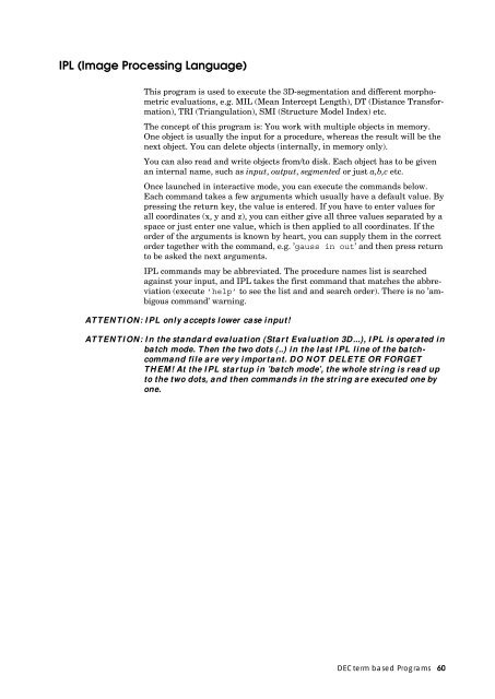
<strong>IPL</strong> (Image Processing Language)<br />
This program is used to execute the 3D-segmentation and different morphometric<br />
evaluations, e.g. MIL (Mean Intercept Length), DT (Distance Transformation),<br />
TRI (Triangulation), SMI (Structure Model Index) etc.<br />
The concept of this program is: You work with multiple objects in memory.<br />
One object is usually the input for a procedure, whereas the result will be the<br />
next object. You can delete objects (internally, in memory only).<br />
You can also read and write objects from/to disk. Each object has to be given<br />
an internal name, such as input, output, segmented or just a,b,c etc.<br />
Once launched in interactive mode, you can execute the commands below.<br />
Each command takes a few arguments which usually have a default value. By<br />
pressing the return key, the value is entered. If you have to enter values for<br />
all coordinates (x, y and z), you can either give all three values separated <strong>by</strong> a<br />
space or just enter one value, which is then applied to all coordinates. If the<br />
order of the arguments is known <strong>by</strong> heart, you can supply them in the correct<br />
order together with the command, e.g. ’gauss in out’ and then press return<br />
to be asked the next arguments.<br />
<strong>IPL</strong> commands may be abbreviated. The procedure names list is searched<br />
against your input, and <strong>IPL</strong> takes the first command that matches the abbreviation<br />
(execute ’help’ to see the list and and search order). There is no ’ambigous<br />
command’ warning.<br />
ATTENTION: <strong>IPL</strong> only accepts lower case input!<br />
ATTENTION: In the standard evaluation (Start Evaluation 3D...), <strong>IPL</strong> is operated in<br />
batch mode. Then the two dots (..) in the last <strong>IPL</strong> line of the batchcommand<br />
file are very important. DO NOT DELETE OR FORGET<br />
THEM! At the <strong>IPL</strong> startup in ’batch mode’, the whole string is read up<br />
to the two dots, and then commands in the string are executed one <strong>by</strong><br />
one.������������������������������������������������������������������<br />
������������������������������������������������������������������������������������<br />
DECterm based Programs 60
help<br />
Gives the list of all available procedures or a short description of a procedure<br />
if ’help xxxx’ is typed.<br />
quit<br />
Quits the program<br />
ipl> quit (or q)<br />
list<br />
Lists all objects currently in memory or lists all procedures, optionally only<br />
items starting with beggining_with.<br />
ipl> list<br />
-objects [true] ><br />
-procedures [false] ><br />
-beginning_with [] ><br />
read<br />
Reads an object from disk. The file type has to be *.aim. By reading an object<br />
from disk, you have to give it an internal name.<br />
ipl> read<br />
-name [in] > a<br />
-filename [default_file_name] > DISK3:[DATA]C0000372.AIM<br />
-type [aim] ><br />
-uncompress [true] ><br />
aim_read<br />
Shortcut for reading an AIM from disk. The file type has to be *.aim. By reading<br />
an object from disk, you have to give it an internal name. Same function<br />
as read, but type and uncompress are assumed to be aim and true.<br />
ipl> aim<br />
-name [in] > a<br />
-filename [default_file_name] > DISK3:[DATA]C0000372.AIM<br />
or on one line only:<br />
ipl> aim in DISK3:[DATA]C0000372.AIM<br />
DECterm based Programs 61
isq_to_aim<br />
Reads an .ISQ from disk and puts the requested volume of interest into memory<br />
as an aim object. The volume of interest is given <strong>by</strong> pos (upper left corner)<br />
and dim (dimension of aim object).<br />
ipl> isq<br />
-aim_name [in] >a<br />
-isq_filename [default_file_name] >DISK3:[DATA]C0000372.ISQ<br />
-pos [0 0 0] >150 240 0<br />
-dim [-1 -1 -1] >210 210 210<br />
write<br />
Writes an object to disk. The file type should be *.aim. You can compress segmented<br />
files using run_length or binary compression. Default is binary, but<br />
for gray-scale images the compress type is always switched internally to none.<br />
ipl> write<br />
-name [default_name] > a<br />
-filename [default_file_name] > DISK3:[DATA]XYZ.AIM<br />
-compress_type [bin] > r<br />
delete<br />
This command is used to delete an internal object, i.e. to free memory.<br />
ipl> delete<br />
-name [] > a<br />
examine<br />
Use this command to examine different things of an object and show the results<br />
on the screen. Possible values are: geometry, histogram, statistics, number,<br />
log, and z_mean_max (mean and max values of each slice along z-axis).<br />
ipl> examine<br />
-input [default_name] > a<br />
-item [geometry] ><br />
!> dim 504 122 223<br />
!> off 0 0 0<br />
!> pos 266 308 0<br />
.<br />
.<br />
sup_divide<br />
This command is used to subdivide an object into smaller objects. This is helpful<br />
in examining only a small part of the complete object or for segmenting the<br />
whole object using small subobjects to save memory. You can either define the<br />
subvolume(s) <strong>by</strong> entering the number of subvolumes (supdim, in all directions)<br />
or their size in pixels (subdim). Suppos is the offset of the object in pix-<br />
DECterm based Programs 62
els in local coordinates. If you leave the value at -1, the object(s) will be centered.<br />
testoff is used for overlapping the small subobjects in case of a procedure<br />
such as a gauss-filter. If supdim_numbers is not a divisor of the original<br />
object’s dimensions, a few voxels may be discarded, at most subdim_number<br />
voxels per direction x, y or z.<br />
ipl> sup_divide<br />
-input [in] > a<br />
-supdim_numbers [-1 -1 -1] > 4<br />
-testoff_pixels [0 0 0] > 2<br />
-suppos_pixels_local [-1 -1 -1] ><br />
-subdim_pixels [-1 -1 -1] ><br />
sub_get<br />
Extracts a sub volume that has the position and size as entered <strong>by</strong> pos and<br />
dim. The flag global_pos_flag controls whether pos is the global position<br />
(given <strong>by</strong> the original measurement) or the local position in the input object.<br />
ipl> sub_get<br />
-input [in] >a<br />
-output [sub] >s<br />
-pos [0 0 0] >10 30 10<br />
-dim [0 0 0] >120<br />
-global_pos_flag [false] ><br />
sub_pick<br />
Is an older version of sub_get, that needs previous execution of sup_divide<br />
to enter the positions and sizes in the grid. subpos_numbers is the (0-based)<br />
position in numbers in the suppos-grid.<br />
ipl> sub_pick<br />
-input [in] >a<br />
-output [sub] >s<br />
-subpos_numbers [0 0 0] ><br />
gauss_lp<br />
This is the command to gauss-filter an object. The shape of the filter can be<br />
given using sigma and support. You have to give an internal name for the output<br />
object.<br />
2 sigma<br />
2 support + 1<br />
ipl> gauss<br />
-input [in] > a<br />
-output [gauss] > b<br />
-sigma [1.000000] > 1.2<br />
-support [2] ><br />
DECterm based Programs 63
threshold<br />
Using this command, you can binarize an object. All voxels below<br />
lower_in_perm and above upper_in_perm will be set to value 0, the rest (the<br />
object) will be given a value of value_in_range, usually 127. The values for the<br />
lower and upper threshold are given in 1/1000, covering the whole range of<br />
the data values (0 to 32767 for gray-scale AIMs, -128 to 127 for char AIMs).<br />
ipl> thresh<br />
-input [gauss] > b<br />
-output [th] > c<br />
-lower_in_perm [300] > 220<br />
-upper_in_perm [1000] ><br />
-value_in_range [127] ><br />
gauss_seg and seg_gauss<br />
Use this command to do the gauss_lp and the threshold in one step. This<br />
saves memory and reduces the computing time. However, you have no access<br />
to the intermediate object.<br />
ipl> gauss_seg (or seg)<br />
-input [in] > a<br />
-output [seg] > b<br />
-sigma [1.000000] > 1.2<br />
-support [2] ><br />
-lower_in_perm [300] > 220<br />
-upper_in_perm [1000] > 1000<br />
-value_in_range [127] ><br />
adaptive_threshold<br />
Using this command, you can find out which threshold leads to the best segmentation<br />
of the bone. The program examines the BV/TV parameter at different<br />
threshold values (given <strong>by</strong> first_threshold, last_threshold and nr_steps). It<br />
then tries to find the threshold with the least change, which it considers to be<br />
the best choice. At the end, this value is applied to the input and written to<br />
the output object using the value_in_range as in threshold.<br />
ipl> adaptive_thresh<br />
-input [gauss] > a<br />
-output [th_adp] > c<br />
-first_threshold [100] > 200<br />
-last_threshold [400] > 300<br />
-nr_steps [30] > 50<br />
-value_in_range [127] ><br />
fft_laplace_hamming<br />
Segmentation of an object based on zero crossing of second derivative. The<br />
second derivative is calculated in the fourier domain <strong>by</strong> applying a w 2 filter,<br />
for noise smoothing a Hamming filter is simultaneously applied. To ensure<br />
that regions with high attenuation are segmented as foreground, the original<br />
image is added with variable weight 1–laplace_epsilon. The result is an object<br />
of type ’float’ that has to be normed to ’short’ again with norm_max.<br />
DECterm based Programs 64
Redim_pow2 can be used to simultaneously interpolate the object to a new<br />
voxel-size <strong>by</strong> fourier interpolation in powers of 2 ( redim_pow2 = 2 -> 4 times<br />
interpolation). Laplace_epsilon controls the weight of the curvature image, the<br />
higher the epsilon, the more ’edge-enhanced’ the image appears.<br />
Lp_cut_off_freq is the Hamming filter low-pass frequency in units half the Nyquist<br />
frequency: 0.5 is a filter rolling off to 0 just at the Nyquist boundary.<br />
Hamming_amp is the amplitude of the Hamming filter, its default is best not<br />
varied.<br />
ipl> fft_laplace<br />
-input [in] >in<br />
-output [lh] >out<br />
-redim_pow2 [0 0 0] ><br />
-laplace_eps [0.900000] ><br />
-lp_cut_off_freq [0.400000] ><br />
-hamming_amp [1.000000] ><br />
norm_max<br />
Norm_max has to be applied after fft_laplace_hamming to convert the<br />
’float’ values to ’short’ again. Max in the input will be set to the maximal possible<br />
value of the chosen data output type type_out (32767 for short), as will<br />
all values above max. The values from zero to max will be scaled to the data<br />
range available for the output data type. With ’examine lh histo’ the histogram<br />
of the fft_laplace output can be viewed, and a suitable max can<br />
thus be chosen, normally a value at the upper end of the main distribution.<br />
The range of the fft_laplace output can vary greatly for different types of<br />
objects, since the curvature can be very different. It is advised, however, to<br />
use the same value for max for one type of sample, i.e. within one study population.<br />
The value is not very crucial, as long as it is above the respective value<br />
that is thresholded afterwards to produce a binary image.<br />
ipl> norm<br />
-input [lh] ><br />
-output [norm] ><br />
-max [50000.000000] ><br />
-type_out [short] ><br />
gobj_maskaimpeel_ow<br />
Performs a masking of an object with a GOBJ (or a AIM-mask, needs more<br />
memory and time with AIM, though). Voxels outside the mask are set to Zero.<br />
Peel_iter gives the number of two-dimensional peel iteration applied to the<br />
contours. The operation is working directly on the object, i.e. it is overwriting<br />
Zeros on it. NB: Gobj_maskaimpeel_ow may be repeatedly used on the same<br />
object, but using a smaller peel_iter number does not restore the region set to<br />
Zero anymore, i.e. while trying out different peel_iters, go from small numbers<br />
upwards. The relative volume of the mask is stored in the proceeding log,<br />
which may be shown with ’examine in log’ afterwards.<br />
ipl> gobj_mask<br />
-input_output [in] >in<br />
-gobj_filename [default_file_name] >U0001977.GOBJ<br />
-peel_iter [0] ><br />
DECterm based Programs 65
cortex_maskoff<br />
Expert function.<br />
Combines a GOBJ contour (e.g. the outer bone contour) with a cortexsegmentation<br />
mask. The resulting AIM-mask is then the region inside the<br />
GOBJ, but without the cortex, i.e. only the trabecular region. The input is a<br />
GOBJ file and a volume that should represent the cortex: input_mask. This<br />
input_mask has to be produces with seg_gauss beforehand (e.g. with a high<br />
sigma 10.0 and support 6, and an approriate threshold 150 or 300.) cortex_peel_iter<br />
gives a minimal cortex thickness, i.e. the minimal boundary of<br />
the outer contour that is excluded in the mask. A component labeling is performed<br />
for every slice for the cortex (-> cl_cortex in percent) and then for the<br />
inner mask (-> cl_inner in percent), in the example below, fro every slice only<br />
parts of the cortex that take up more than 50% are considered for the<br />
slicewise exclusion, and then only parts making up more than 60% are taken<br />
for the mask.<br />
ipl> cortex_mask<br />
-input_mask [in] ><br />
-gobj_filename [default_file_name] >u0001234.GOBJ<br />
-output [out] ><br />
-cortex_peel_iter [5] ><br />
-cl_cortex [10.000000] >50.<br />
-cl_inner [10.000000] >60.<br />
gobj_to_aim<br />
Produces a solid, filled volume from a GOBJ file, i.e. the inside of the GOBJ<br />
mask. This function is needed if the element-size (voxelsize) of the original<br />
volume or segmented volume has been changed with scale_el_size, e.g. to<br />
make the voxels cubic. Then the GOBJ produced on the original ISQ file does<br />
not match anymore, but the AIM-mask produced with gobj_to_aim can be<br />
scaled to the appropriate voxel size (scale with integrate false), written to<br />
disk and then used in gobj_maskaimpeel_ow. Also any other <strong>IPL</strong> commands<br />
can be applied to the AIM-mask like to any other binary volume.<br />
ipl> gobj_to_aim<br />
-gobj_filename [default_file_name] >U0001977.GOBJ<br />
-output [out] >out<br />
-peel_iter [0] ><br />
cut2d_shape_ow<br />
Cut a two-dimensional ellipse, circle, or rectangle extended along the z-axis<br />
from an object and set all points lying outside to zero. The size of the shape<br />
type_of_shape is adjusted to the biggest size lying within the x-y plane, if -1 is<br />
chosen for halfaxes_x_y, otherwise to the given size (may overlap the boundary).<br />
Cutborder controls whether the border of the shape is set to zero (true)<br />
or not (false). The operation is overwriting, i.e. the input object is altered !<br />
ipl> cut2d_shape<br />
-input_output [in] ><br />
-type_of_gobj [circle] ><br />
-halfaxes_x_y [-1 -1] ><br />
-midpos_x_y [-1 -1] ><br />
-cutborder [false] ><br />
DECterm based Programs 66
cl_ow_rank_extract<br />
Component labeling (CL) of a segmented image. Faces have to touch for voxels<br />
to be considered connected, i.e. a voxel can have 6 connected neighbours. Extracts<br />
the regions with the given rank in the size-ordered table. Overwrites<br />
the input. Usually used with rank 1 to 1 to remove any small noisy speckels<br />
not connected to the main structure. Connect_boundary controls whether the<br />
whole boundary of the box containing the object acts as a connector of surface<br />
points.<br />
ipl> cl<br />
-input_output [seg] >a<br />
-first_rank [1] ><br />
-last_rank [1] ><br />
-connect_boundary [false] ><br />
-value_in_range [127] ><br />
cl_rank_extract<br />
Same as above, but not overwriting the input. Uses more memory.<br />
ipl> cl_rank<br />
-input [seg] ><br />
-output [cl] ><br />
-first_rank [1] ><br />
-last_rank [1] ><br />
-connect_boundary [false] ><br />
-value_in_range [127] ><br />
cl26_rank_extract<br />
Similar as above, but also voxels only touching <strong>by</strong> an edge are considered connected.<br />
ipl> cl26_rank<br />
-input [seg] ><br />
-output [cl] ><br />
-first_rank [1] ><br />
-last_rank [1] ><br />
-connect_boundary [false] ><br />
-value_in_range [127] ><br />
cl_extract<br />
Same as cl_rank_extract, but extracting according to fractional volume of<br />
components. Not available with connect_boundary flag.<br />
ipl> cl_extract<br />
-input [seg] ><br />
-output [cl] ><br />
-lo_vol_fract_in_perc [1] ><br />
-up_vol_fract_in_perc [1] ><br />
-value_in_range [127] ><br />
DECterm based Programs 67
cl_nr_extract<br />
Same as cl_rank_extract, but extracting according to number of voxels of components.<br />
Not available with connect_boundary flag.<br />
ipl> cl_nr_extract<br />
-input [seg] ><br />
-output [cl] ><br />
-min_number [10] ><br />
-max_number [0] ><br />
-value_in_range [127] ><br />
cl_image<br />
Gives the component labeled image as output, with value 127 for biggest connected<br />
part, 126 for second biggest etc.<br />
ipl> cl_image<br />
-input [seg] ><br />
-output [cl] ><br />
db_scanco_activate<br />
Activates (or deactivates) the database for writing all subsequent evaluation<br />
results into it. It stays activated until db_scanco_activate false is entered.<br />
ipl> db_scanco_activate<br />
-write [true] ><br />
tri_da_metric_db<br />
This command triangulates a segmented object and calculates object volume<br />
and surface as well as the structure model index (SMI). Using the plate<br />
model, trabecular number, thickness and separation are derived.<br />
Tri_da_metric_db uses the contours of a GOBJ or AIM-mask if it finds the<br />
GOBJ filename in the proceedings log. Otherwise, the whole box region is<br />
evaluated. The results are written into the database (->db), if the database<br />
was activated, see db_scanco_activate.<br />
You should usually not modify the default values of the arguments ip_sigma,<br />
ip_support, ip_threshold, interpolate, nr-ave_iter, t_dir_radius, epsilon.<br />
The output is an object with nr_views different 3D views of the triangulated<br />
object. This output may be written to disk with ’msq_from_aim’ and viewed<br />
with the 3D-Disply program.<br />
ipl> tri<br />
-input [th] >seg<br />
-output [tri] ><br />
-gobj_filename [gobj_from_log] ><br />
-peel_iter [-1] ><br />
-ip_sigma [2.000000] ><br />
-ip_support [1] ><br />
-ip_threshold [64] ><br />
-interpolate [true] ><br />
-nr_ave_iter [0] ><br />
DECterm based Programs 68
-t_dir_radius [2] ><br />
-epsilon [1.200000] ><br />
-size_image [512 512] ><br />
-scale_image [0.700000] ><br />
-edges [false] ><br />
-nr_views [0] ><br />
dt_object_param<br />
Calculates the mean thickness of the structure with the distance transformation<br />
(DT) method <strong>by</strong> filling largest spheres into the object and calculating<br />
their mean diameter (volume weighted mean). Mean thickness and standard<br />
deviation are written to the database, if activated. The output object shows<br />
the spheres fitting inside the structure with the voxel values being their diameter<br />
in voxel units. Dt_object_param uses the contours of a GOBJ or<br />
AIM-mask if it finds the GOBJ filename in the proceedings log.<br />
Roi_radius_factor controls whether only a sphere is evaluated or the whole region<br />
(default). DT also works with GOBJ-masked objects. The epsilons are<br />
used for suppressing artefacts due to rough surfaces. You should ususally not<br />
modify the default values. (For very coarse voxel sizes above 100 µm, assign_epsilon<br />
0.9 may be chosen.) Histogram_or_screen controls whether a histogram<br />
of the thickness distribution is written to a textfile and/or shown on<br />
the screen.<br />
ipl> dt_obj<br />
-input [in] ><br />
-output [out] ><br />
-gobj_filename [gobj_from_log]<br />
-peel_iter [-1]<br />
-roi_radius_factor [10000.0] ><br />
-ridge_epsilon [0.900000] ><br />
-assign_epsilon [1.800000] ><br />
-histofile_or_screen [none] >samp012_thickness.tab<br />
dt_background_param<br />
Calculates the mean separation of the structure with the distance transformation<br />
(DT) method <strong>by</strong> filling largest spheres into the background of the object<br />
and calculating their mean diameter (volume weighted mean). Mean sparation<br />
and standard deviation are written to the database, if activated. The output<br />
object shows the spheres fitting inside the background with the voxel values<br />
being their diameter in voxel units. Dt_background_param uses the<br />
contours of a GOBJ or AIM-mask if it finds the GOBJ filename in the proceedings<br />
log. Roi_radius_factor controls whether only a sphere is evaluated or the<br />
whole region (default). DT also works with GOBJ-masked objects. The epsilons<br />
are used for suppressing artefacts due to rough surfaces. You should<br />
ususally not modify the default values. (For very coarse voxel sizes above<br />
100 µm, assign_epsilon 0.9 may be chosen.) Histogram_or_screen controls<br />
whether a histogram of the thickness distribution is written to a textfile<br />
and/or shown on the screen.<br />
ipl> dt_back<br />
-input [in] ><br />
-output [out] ><br />
-gobj_filename [gobj_from_log]<br />
-peel_iter [-1]<br />
-roi_radius_factor [10000.0] ><br />
-ridge_epsilon [0.900000] ><br />
DECterm based Programs 69
-assign_epsilon [1.800000] ><br />
-histofile_or_screen [none] ><br />
dt_mat_param<br />
Calculates the mean trabecular number of the structure with the distance<br />
transformation (DT) method <strong>by</strong> filling largest spheres into the background of<br />
the mid axis transformed object (->mat) and calculating their mean diameter<br />
(volume weighted mean). Mean number and standard deviation are written to<br />
the database, if activated. The output object shows the spheres fitting inbetween<br />
the mid axis structure with the voxel values being their diameter in<br />
voxel units. Dt_mat_param uses the contours of a GOBJ or AIM-mask if it<br />
finds the GOBJ filename in the proceedings log.Roi_radius_factor controls<br />
whether only a sphere is evaluated or the whole region (default). DT also<br />
works with GOBJ-masked objects. The epsilons are used for suppressing artefacts<br />
due to rough surfaces. You should ususally not modify the default values.<br />
(For very coarse voxel sizes above 100 µm, assign_epsilon 0.9 may be chosen.)<br />
Histogram_or_screen controls whether a histogram of the thickness<br />
distribution is written to a textfile and/or shown on the screen.<br />
ipl> dt_mat<br />
-input [in] ><br />
-output [out] ><br />
-gobj_filename [gobj_from_log]<br />
-peel_iter [-1]<br />
-roi_radius_factor [10000.0] ><br />
-ridge_epsilon [0.900000] ><br />
-assign_epsilon [1.800000] ><br />
-histofile_or_screen [none] ><br />
dt_mat_output<br />
Performs the mid axis transformation of the structure and saves the mid axes<br />
in the output.<br />
ipl> dt_mat_output<br />
-input [in] ><br />
-output [out] ><br />
-ridge_epsilon [0.900000] ><br />
connectivity<br />
Calculates the connectivity density of a segmented object, according to Odgaard<br />
and Gundersen (Bone 14:173-182;1993). The insure that only one connected<br />
object and one connected background is evaluated, a component labeling<br />
and extraction of the dominant component is performed for both the<br />
foreground and the background. Use conn_nocl and conn_bgcl if you wish<br />
no component labeling or only a background component labeling/extraction,<br />
e.g. if a component labeling is already incorporated into the segmentation.<br />
Attention: the component labeling and extraction changes the input volume !<br />
ipl> connectivity<br />
-in_out [in] ><br />
DECterm based Programs 70
conn_nocl<br />
Calculates the connectivity density of a segmented object without prior component<br />
labeling. If the object consists of more than one unconnected part, you<br />
would have to add the number of components minus one to the connectivity,<br />
and then calculate the connectivity density. Likewise, if the background is<br />
made up of more than one part, you would have to add the number of backround<br />
components minus one.<br />
ipl> conn_nocl<br />
-in_out [in] ><br />
conn_bgcl<br />
Calculates the connectivity density of a segmented object with only component<br />
labeling and extraction of the background. If the object consists of more than<br />
one unconnected part, you would have to add the number of components minus<br />
one to the connectivity, and then calculate the connectivity density.<br />
Attention: the component labeling and extraction changes the input volume !<br />
ipl> conn_bgcl<br />
-in_out [in] ><br />
voxgobj_scanco_param<br />
Evaluates a segmented image for the fraction of voxels set and writes result to<br />
the database (if activated). For gray scale (original) images, mean attenuation<br />
coefficient is written to database. The object is masked again with the given<br />
GOBJ or AIM-mask. By default, the GOBJ filename is taken from the proceedings<br />
log (last occurence of a GOBJ filename). If the GOBJ file is not<br />
found, vox_scanco_param (see below) is applied. Peel_iter controls the number<br />
of 2D peel iterations for the mask. By default, peel_iter is taken from the<br />
proceedings log.<br />
ipl> vox<br />
-input seg<br />
-gobj_filename gobj_from_log<br />
-peel_iter -1<br />
vox_scanco_param<br />
Evaluates a segmented image for the fraction of voxels set and writes result to<br />
the database (if activated). For gray scale (original) images, mean attenuation<br />
coefficient is written to database. If the proceedings log of the object contains<br />
a GOBJ mask operation, the relative volume of the masked region is incorporated<br />
into the calculation.<br />
ipl> vox_scanco seg<br />
DECterm based Programs 71
mil_param<br />
This command executes the MIL-calculations (Mean Intercept Length, Parfitt).<br />
You should usually not modify the default values. If the database is activated,<br />
the result of the calculations are written to the evaluation-database.<br />
ipl> mil_param<br />
-input [default_name] > a<br />
-ray_plane_scale [2.000000] ><br />
-roi_radius_factor [1.000000] ><br />
-t_dir_ortho [no] ><br />
-t_dir_ortho_nr [8] ><br />
-t_dir_radius [2] ><br />
-fabric_tensor [yes] ><br />
milv1_param<br />
This command executes the MIL-calculations in its first version (different border<br />
handling). You should usually not modify the default values. If the database<br />
is activated, the result of the calculations are written to the evaluationdatabase.<br />
ipl> milv1<br />
-input [default_name] > a<br />
-ray_plane_scale [2.000000] ><br />
-roi_radius_factor [1.000000] ><br />
-t_dir_ortho [no] ><br />
-t_dir_ortho_nr [8] ><br />
-t_dir_radius [2] ><br />
-fabric_tensor [yes] ><br />
histo<br />
Gives a histogram of an object. With the default arguments same effect as<br />
’examine in histo’. Optionally, the histogram is shown from from_val to<br />
to_val, default from minimal value to maximal value found in input volume.<br />
Optionally, a tabulated version of the histogram is printed to a file (given with<br />
fileout_or_screentab) or the screen (fileout_or_screentab screen, in addition to<br />
the bar-column representation) with the number of bins given with<br />
nr_bins_in_tab. The number of bins in the bar-column representation is not<br />
affected <strong>by</strong> nr_bins_in_tab !<br />
ipl> histo<br />
-input [in] >rat<br />
-fileout_or_screentab [none] > my_histo.tab<br />
-from_val [-1] >1500<br />
-to_val [-1] >3000<br />
-nr_bins_in_tab [-1] ><br />
scale_elsize<br />
Using this command you can change the voxelsize of your object. down_scale<br />
enlarges the voxelsize (reduces the resolution), up_scale makes the voxelsize<br />
finer. Non-integer scaling can either be given directly, e.g. with down_scale<br />
1.5; or with a combination of down_scale 3 and up_scale 2. The effect is exactly<br />
the same, the latter may just save you a division <strong>by</strong> hand. The integrate<br />
DECterm based Programs 72
flag controls whether averaging of voxels is done in downscaling (and potential<br />
interpolation of partial voxels) and whether interpolation is done in upscaling.<br />
It is suggested to use integrate true for gray-scale images, but integrate<br />
false for binary segmented images to preserve the binary status.<br />
Otherwise a subsequent thresholding operation may be needed to ensure a binary<br />
image again.<br />
Scale_elsize automatically selects among the below described procedures<br />
ipscale_elsize and noipscale_elsize, according to whether there are<br />
fractional voxels who may then be interpolated (->ip): For integer downscalings<br />
noipscale is chosen, for non-integer down-scalings and any upscalings<br />
ipscale is chosen. The exception is non-averaging scaling of binary<br />
objects always with noipscale to maintain the binary status, if the integrate<br />
flag is put on false.<br />
If a GOBJ mask is used for the evaluation of an object, the GOBJ mask has to<br />
be transformed into an AIM mask with gobj_to_aim, and this AIM mask<br />
can then be scaled to the same voxelsize as the original object. Use integrate<br />
false for the mask scaling to preserve the binary status of the mask (alternatively,<br />
after masking with integrate true, perform a threshold operation to<br />
produce a binary mask again).<br />
ipl> scale<br />
-input [in] > a<br />
-output [sca]> x<br />
-down_scale [2.000 2.000 2.000] ><br />
-up_scale [1.000 1.000 1.000] ><br />
-integrate [true] ><br />
ipscale_elsize<br />
One constituent of scale_elsize. If the new voxel-grid is not a integer multiple<br />
of the original voxel-grid, then the new values lying between old voxels<br />
points are interpolated (-> ip), and depending on the integrate flag also averaged<br />
over the voxelvolume. The center flag controls whether the center of the<br />
object is still in the center of the scaled object, or whether the upper left top<br />
corner is also the beginning of the scaled object (center false). The computation<br />
time and memeory needed is larger than for noipscale_elsize.<br />
ipl> ipscale_elsize<br />
-input [in] >a<br />
-output [sca] >b<br />
-down_scale[2.000 2.000 2.000] >1<br />
-up_scale [1.000 1.000 1.000] >2<br />
-center [false] ><br />
-integrate [true] ><br />
noipscale_elsize<br />
Scales the objects without interpolating non-integer voxel locations in the<br />
scaled object, but takes nearest neighbour approach. Computationally faster<br />
and uses less memory, but nearest neighbour choice may create less accurate<br />
scaling. Does not account for fractional voxels for non-integer scaling, even if<br />
average flag is true, e.g. for down_scale 2.6 and average true, only 2 voxels are<br />
averaged (per direction).<br />
ipl> noipscale<br />
-input [in] > a<br />
DECterm based Programs 73
-output [sca] x<br />
-down_scale [2.000 2.000 2.000] ><br />
-up_scale [1.000 1.000 1.000] ><br />
-average [true] ><br />
scale_ow_elsize_noip<br />
Same as noipscale_elsize, but overwrites input. Saves memory. Does not<br />
work for increasing resolution, since output memory would have to be bigger<br />
than input memory.<br />
ipl> noipscale<br />
-input_output [in] > a<br />
-down_scale [2.000 2.000 2.000] ><br />
-up_scale [1.000 1.000 1.000] ><br />
-average [true] ><br />
set_value<br />
With this command you can set the value of all non-zero voxels of a segmented<br />
object to a given value and all zero voxels to another. Useful for inverting<br />
foreground/background of the object and for producing a negative image<br />
(value_object -127).<br />
ipl> set_val<br />
-input [in] ><br />
-value_object [127] ><br />
-value_background [0] ><br />
concat<br />
Concatenates two objects. Common_region_only: if two objects with unequal<br />
dimensions or unequal positions are chosen, this flag controls whether the region<br />
common to both objects is taken; or whether the box region surrounding<br />
both objects is produced. Add_not_overlay: Controls whether voxel values of<br />
second object are added to the first object - with overflow taken care of, i.e.<br />
60+90=127+50=127 for char images; or wheter non-zero values are layed over<br />
the first object, useful for mapping the segmented image onto the original<br />
gray-scale data. Make_edge: controls whether edges are made of second object<br />
(or first, if second is gray-scale and first is char). The second object can be<br />
shifted with shift_ofin2 and turned in the x-y plane with turnangle.<br />
Turnpoint_global is tried to be set to the original rotation center of the scanner,<br />
i.e. for 512x512 images to 256,256 etc. The turned image2 is mapped into<br />
the same box as image2, thus for larger angles the image may be cut at the<br />
boundary if there is not enough free space left around the object to contain the<br />
turned image2. Subtraction of two binary images can be performed <strong>by</strong> a combination<br />
of /set_value of input2 to -127 and then concat it with input1, flag<br />
add true.<br />
ipl> concat<br />
-input1 [in] >a<br />
-input2 [in1] >b<br />
-output [out] >c<br />
-common_region_only [true] ><br />
-add_not_overlay [true] ><br />
DECterm based Programs 74
-make_edge [false] ><br />
-shift_ofin2 [0 0 0] ><br />
-turnangle [0.000000] ><br />
-turnpoint_global [-1 -1] ><br />
join_uncompress<br />
This operation joins two segmented volumes directly while reading and uncompressing<br />
from the disk, thus only needs the memory of the output volume<br />
once. It may be useful if concat does not work because of too small virtual<br />
memory. The compressed files are read from disk and the uncompressing is<br />
done directly into the correct memory location in the output. The volumes<br />
may be overlapping, but then the respective part of file2 is overwritten (including<br />
zeros) onto file1.<br />
NOTE: Join_uncompress only works for compressed files on disk and only<br />
works for volumes with the same dimensions in x and y direction !<br />
ipl> /join<br />
-file1 [file1] >rat_seg_part1.aim<br />
-file2 [file2] >rat_seg_part2.aim<br />
-output [out] ><br />
-shift_ofin2_z [0] ><br />
bounding_box_cut<br />
This operation determines the smallest box around the object of non-zero<br />
voxels. An additional boundary can be chosen with border. z_only controls if<br />
only the bounding box in z direction is determined and cut out with a given<br />
border.<br />
ipl> /bounding_box_cut<br />
-input1 [in] ><br />
-output [out] ><br />
-z_only [false] ><br />
-border [0 0 0] ><br />
flip_aim<br />
Flips an object to a side, i.e. x y and z direction are switched according to<br />
new_xydir (NB: it is not necessarily a proper rotation of the object in 3D<br />
space !). The new x direction is the first letter given in new_xydir, the new y<br />
direction is the second letter, the new z direction is the remaining direction.<br />
ipl> flip_aim<br />
-input [in] >a<br />
-output [out] >f<br />
-new_xydir [yz] >xz<br />
offset_add<br />
Changes the offset around the object. The offset is the same for the beginning<br />
and the end for one direction (voxels run from +off.x to dim.x-off.x), but may<br />
DECterm based Programs 75
e different for the different directions x, y and z. The offset is then disregarded<br />
in subsequent image processing or statistical examinations.<br />
ipl> offset_add<br />
-input [in] >a<br />
-add_offset [0 0 0] >0 0 4<br />
offset_set<br />
Changes the offset around the object, independent of what it was before.<br />
ipl> offset_set<br />
-input [in] >b<br />
-new_offset [0 0 0] >2 2 1<br />
clear_offset<br />
Sets all voxels in the (optionally new) offset to zero.<br />
ipl> offset_set<br />
-input [in] >b<br />
-new_offset [-1 -1 -1] >2 2 1<br />
fill_offset_mirror<br />
Fills the offset of an object with the mirrored values just to the inside of the<br />
offset. May be used after operations that ’steal’ from the image, e.g. gaussfilter.<br />
Be aware that voxel information is just duplicated and that values calculated<br />
afterwards can be biased.<br />
ipl> fill_offset_mirror<br />
-input [in] > in<br />
convert_to_type<br />
This converts objects from one input type to another, e.g. a ’char’ image to a<br />
’short’ image. The output type is given <strong>by</strong> out_type.<br />
ipl> convert_to_type<br />
-input [in] ><br />
-output [out] ><br />
-out_type [short] ><br />
xray<br />
Produces a virtual (linear) xray image of the object along the z-axis (flip the<br />
object with ’flip_aim’ first for other desired orientations). The output is a<br />
’char’ image. The voxel values (for every x and y) are added along the z-axis<br />
from startslice for number_of_slices, and the sum is either normalized with<br />
the largest occuring voxelsum (fixed_norm_char false) or to a fixed norm for<br />
binary input volumes (fixed_norm_char true).<br />
DECterm based Programs 76
ipl> xray<br />
-input [in] ><br />
-output [out] ><br />
-startslice [0] ><br />
-number_of_slices [16] ><br />
-fixed_norm_char [true] ><br />
msq_from_aim<br />
Write an object in memory to disk in the .MSQ format, e.g. to view it with the<br />
3D-Display program.<br />
ipl> msq<br />
-aim_name [out] ><br />
-msq_filename [default_file_name] ><br />
from_aim_to_isq<br />
Write an object in memory to disk in the .ISQ format, e.g. to produce a GOBJ<br />
with the Evaluation program again. The object will be at its original (global)<br />
position.<br />
ipl> from_aim_to_isq<br />
-aim_name [out] ><br />
-isq_filename [default_file_name] ><br />
For an extensive discussion of the obtained structural indices see Appendix<br />
(Explanation of Structural Indices, p.100).<br />
Use this program to recreate a 3D-result-sheet including the 3D-image and<br />
the histomorphometry-values calculated <strong>by</strong> <strong>IPL</strong>.<br />
DECterm based Programs 77