Thyristor Controlled Battery Chargers.pdf - Schaefer Converters
Thyristor Controlled Battery Chargers.pdf - Schaefer Converters
Thyristor Controlled Battery Chargers.pdf - Schaefer Converters

You also want an ePaper? Increase the reach of your titles
YUMPU automatically turns print PDFs into web optimized ePapers that Google loves.
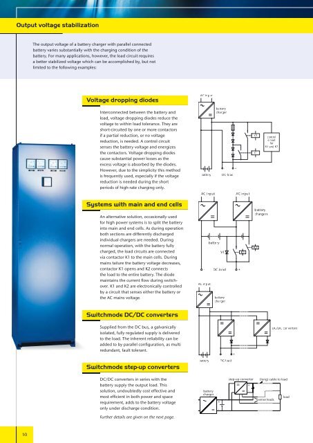
Output voltage stabilization<br />
10<br />
The output voltage of a battery charger with parallel connected<br />
battery varies substantially with the charging condition of the<br />
battery. For many applications, however, the load circuit requires<br />
a better stabilized voltage which can be accomplished by, but not<br />
limited to the following examples:<br />
Voltage dropping diodes<br />
Interconnected between the battery and<br />
load, voltage dropping diodes reduce the<br />
voltage to within load tolerance. They are<br />
short-circuited by one or more contactors<br />
if a partial reduction, or no voltage<br />
reduction, is needed. A control circuit<br />
senses the battery voltage and energizes<br />
the contactors. Voltage dropping diodes<br />
cause substantial power losses as the<br />
excess voltage is absorbed by the diodes.<br />
However, due to the simplicity this method<br />
is frequently used, especially if the voltage<br />
reduction is needed during the short<br />
periods of high-rate charging only.<br />
Systems with main and end cells<br />
An alternative solution, occasionally used<br />
for high power systems is to split the battery<br />
into main and end cells. As during operation<br />
both sections are differently discharged<br />
individual chargers are needed. During<br />
normal operation, with the battery fully<br />
charged, the load circuits are connected<br />
via contactor K1 to the main cells. During<br />
mains failure the battery voltage decreases,<br />
contactor K1 opens and K2 connects<br />
the load to the entire battery. The diode<br />
maintains the current fl ow during switchover.<br />
K1 and K2 are electronically controlled<br />
by a circuit that senses either the battery or<br />
the AC mains voltage.<br />
Switchmode DC/DC converters<br />
Supplied from the DC bus, a galvanically<br />
isolated, fully regulated supply is delivered<br />
to the load. The inherent reliability can be<br />
added to by parallel confi guration, as multi<br />
redundant, fault tolerant.<br />
Switchmode step-up converters<br />
DC/DC converters in series with the<br />
battery supply the output load. This<br />
solution, undoubtedly cost effective and<br />
most effi cient in both power and space<br />
requirement, adds to the battery voltage<br />
only under discharge condition.<br />
Further details are given on the next page.<br />
AC input<br />
battery r<br />
AC input<br />
battery r<br />
www.schaeferpower.de<br />
battery r<br />
charger<br />
V1<br />
- +<br />
DC-load<br />
- DC-load +<br />
AC input<br />
battery r<br />
battery<br />
charger<br />
battery r<br />
charger<br />
+<br />
-<br />
- +<br />
DC-load<br />
AC input<br />
K1<br />
K2<br />
K1<br />
battery r<br />
chargers<br />
K2<br />
control<br />
circuit<br />
for<br />
K1 and K2<br />
step-up converter (long) cable to load<br />
+<br />
-<br />
sense leads<br />
DC/DC converters<br />
load