Thyristor Controlled Battery Chargers.pdf - Schaefer Converters
Thyristor Controlled Battery Chargers.pdf - Schaefer Converters
Thyristor Controlled Battery Chargers.pdf - Schaefer Converters

Create successful ePaper yourself
Turn your PDF publications into a flip-book with our unique Google optimized e-Paper software.
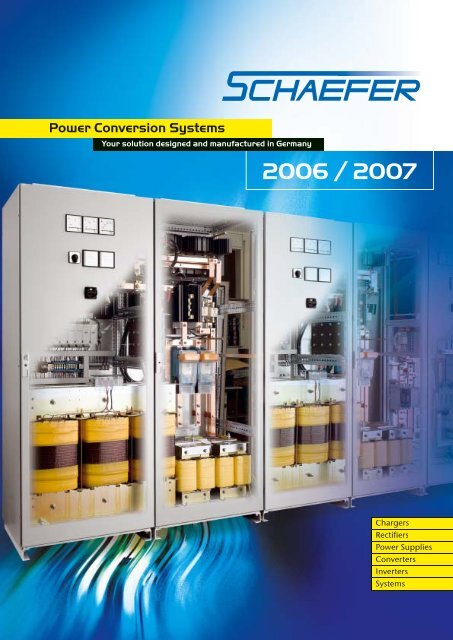
Power Conversion Systems<br />
Your solution designed and manufactured in Germany<br />
2006 / 2007<br />
<strong>Chargers</strong><br />
Rectifi ers<br />
Power Supplies<br />
<strong>Converters</strong><br />
Inverters<br />
Systems
Company profi le<br />
workforce<br />
experience<br />
client orientation<br />
fl exibility<br />
reliability<br />
quality<br />
contact<br />
and has grown to a dedicated workforce of 140 people.<br />
Thanks to decades of experience in design and<br />
manufacturing of power supplies, <strong>Schaefer</strong> offers a large<br />
variety of products, options, and enhancement features. In<br />
the fi eld of high power requirements, <strong>Schaefer</strong> has achieved<br />
and continues to command a leading position.<br />
Consultation and co-operation between the <strong>Schaefer</strong> team<br />
and the client / clients’ representatives or consultants, aims to<br />
choose or adapt a <strong>Schaefer</strong> solution to the clients’ needs.<br />
With the production located next to the development<br />
department an optimum reaction can be accomplished<br />
during all stages of a project. Hence the client gets tailormade<br />
solutions for large or small quantity requirements.<br />
<strong>Schaefer</strong> power solutions are used for applications which<br />
often demand a high level of reliability under severe<br />
environmental conditions such as, but not limited to:<br />
■ Power generation plants<br />
■ Oil & Gas industry<br />
■ Desalination plants<br />
■ Chemical plants<br />
■ Industrial automation<br />
■ Telecommunication<br />
■ Transport on board & way side<br />
■ Military industry<br />
Development guidelines, arduous selection of industrial<br />
components regarding their load criteria and temperature<br />
performance as well as many test procedures during all steps<br />
of production ensure the highest product quality. In addition,<br />
<strong>Schaefer</strong> pursues a full supplier management according to<br />
ISO 9001 which guarantees permanent improvement of the<br />
products especially within the turbulent market of electronic<br />
components.<br />
Through headquarters in Germany, a local branch offi ce in<br />
the UAE and an inter national network of representatives,<br />
<strong>Schaefer</strong> can offer prompt technical support worldwide.
<strong>Thyristor</strong>-controlled power supplies and battery chargers<br />
1<br />
Specifi cations<br />
Input<br />
Voltage. . . . . . . . . . . . . . . . . . . . 230 VAC ±10 %, 1-phase or<br />
400 VAC ±10 %, 3-phase<br />
(other voltages upon request)<br />
Frequency . . . . . . . . . . . . . . . . . 50 or 60 Hz ±5 %<br />
Current. . . . . . . . . . . . . . . . . . . . see tables of page 6 / 7<br />
Protection. . . . . . . . . . . . . . . . . . by fuse<br />
Output<br />
Nominal voltage . . . . . . . . . . . . see tables of page 6 / 7<br />
(other voltages upon request),<br />
adjustable from 90 – 120 % of Unom Line regulation (±10 %) . . . . . . ±0.5 %<br />
Load regulation (10 – 90 %). . . ±1 %<br />
Dynamic load (10 - 90 - 10 %) . . ±10 % typical<br />
Ripple. . . . . . . . . . . . . . . . . . . . . ≤ 5 % rms without battery, optional:<br />
< 2 % rms or 2 mV frequency weighted<br />
Nominal current t . . . . . . . . . . . . see tables of page 6 / 7,<br />
electronic current limitation<br />
adjustable from 60 – 105 % of Inom Overload protection . . . . . . . . . short circuit protected by fuse,<br />
optional: by electronic fuse<br />
Charging characteristic . . . . . . . IU acc. to DIN 41773 for Pb batteries /<br />
DIN 41774 for NiCd batteries<br />
Charging voltage<br />
- fl oat t . . . . . . . . . . . . . . . . . . . . . 2.23 – 2.27 V/cell for Pb batteries /<br />
1.4 V/cell for NiCd batteries<br />
- equalize . . . . . . . . . . . . . . . . . . 2.35 – 2.4 V/cell for Pb batteries /<br />
1.55 V/cell for NiCd batteries<br />
- boost (manual activated) . . . . 2.7 V/cell for Pb batteries /<br />
1.7 V/cell for NiCd batteries<br />
General<br />
Effi ciency<br />
- Series QE . . . . . . . . . . . . . . . . . 78 – 90 %<br />
- Series QD . . . . . . . . . . . . . . . . . 82 – 92 % for models < 48 VDC<br />
85 – 95 % for models ≥ 48 VDC<br />
Operating temperature. . . . . . . –10 to + 40 °C, optional up to + 65 °C<br />
Humidity . . . . . . . . . . . . . . . . . . up to 95 % RH, non-condensing<br />
Altitude . . . . . . . . . . . . . . . . . . . up to 1000 m asl<br />
Cooling . . . . . . . . . . . . . . . . . . . natural convection<br />
Audible noise. . . . . . . . . . . . . . . 50 – 70 dB(A) depending on power<br />
Safety / Construction. . . . . . . . . acc. to DIN / EN 60950-1: 2003<br />
EMI. . . . . . . . . . . . . . . . . . . . . . . acc. to EN 55022, class A<br />
Enclosure<br />
- Protection category . . . . . . . . . IP20 acc. to EN 60529,<br />
optional up to IP55<br />
- Color r . . . . . . . . . . . . . . . . . . . . RAL 7035, others upon request<br />
Transformer r . . . . . . . . . . . . . . . . acc. to IEC 76 / IEC 14 / EN 60591 /<br />
DIN VDE 0532
2<br />
Type test certifi cates<br />
<strong>Battery</strong> charger<br />
<strong>Battery</strong> charger<br />
Submittal of chargers to<br />
an independent laboratory<br />
for Type Test Certifi cation<br />
has been required for both<br />
small and large capacity<br />
chargers.<br />
The manufacturer reserves the right<br />
to deviate from technical details given.
DIN EN ISO 9001 Certifi cate<br />
<strong>Battery</strong> charger<br />
Table of contents<br />
<strong>Thyristor</strong>-controlled<br />
<strong>Thyristor</strong>-controlled power supplies<br />
and battery chargers<br />
from 100 W to 500 kW<br />
with isolation<br />
Page<br />
Specifi cations 1<br />
Type test certifi cates 2<br />
General information & Design solutions 4<br />
QE series, 1-phase thyristor-controlled rectifi ers 6<br />
QD series, 3-phase thyristor-controlled rectifi ers 7<br />
Options & Accessories 8<br />
Control & Supervision 9<br />
Output voltage stabilization 10<br />
Switchmode<br />
DC/DC Step-up converters 11<br />
from 50 W to 10 kW<br />
without isolation<br />
DC/DC converters 12<br />
from 50 W to 40 kW<br />
with isolation<br />
AC/DC power supplies and battery chargers 13<br />
from 50 W to 40 kW<br />
with isolation<br />
DC/AC inverters, AC/AC frequency<br />
converters and static switches<br />
from 200 VA to 36 kVA<br />
with isolation<br />
Design solutions 15<br />
1<br />
14<br />
3
<strong>Thyristor</strong>-controlled power supplies and battery chargers<br />
4<br />
■ Input voltage: 115 / 230 VAC, single phase, 50 / 60 Hz<br />
or 208 / 400 / 480 VAC, 3-phase, 50 / 60 Hz<br />
■ Output voltage: 12 / 24 / 48 / 60 / 72 / 110 / 220 / 400 VDC<br />
■ Output current: up to 3250 A<br />
■ Output power: 100 W - 500 kW<br />
The thyristor-controlled power supplies and battery chargers<br />
present the conventional method of rectifying and controlling<br />
electric power. The advantages of thyristor-controlled units a<br />
given by a simple technical concept resulting in robustness<br />
and reliability.<br />
Typical applications<br />
■ Power generation plants<br />
■ Switch gear stations<br />
■ Oil & Gas industry<br />
- pumping stations<br />
- valve stations<br />
- corrosion protection systems<br />
- DC systems<br />
■ Desalination plants<br />
■ Chemical plants<br />
■ Industrial automation<br />
■ Telecommunication<br />
■ Transport on board & way side<br />
■ Hospitals<br />
www.schaeferpower.de
www.schaeferpower.de<br />
Design Solutions<br />
400 kW Aircraft Starter System<br />
wer Supply System<br />
onfi guration<br />
nductive turbine load<br />
200 kW DC Power Network<br />
■ 110 VDC Power Supply System<br />
■ Dual 800 A confi guration<br />
■ Fully operational up to +55 °C<br />
■ IP42<br />
5
QE Series single phase thyristor-controlled rectifi ers, 100 W – 5 kW<br />
6<br />
L1<br />
Q1<br />
V1<br />
V2<br />
L-<br />
- BATTERY<br />
F1<br />
T1<br />
enclosure<br />
size 1)<br />
R2<br />
R3<br />
R4<br />
R5<br />
R5+<br />
L1<br />
C1<br />
V3<br />
V4<br />
N<br />
R5<br />
F4<br />
F6<br />
A P5<br />
L+<br />
+ BATTERY<br />
THYRISTOR CONTROL<br />
A1<br />
F31 F32<br />
1L- 1L+<br />
DC-LOAD<br />
P6<br />
V<br />
nominal output voltage approx. line<br />
12 V 24 V 48 V 60 V 110 V 220 V<br />
max. output current [A]<br />
current 2)<br />
[A]<br />
www.schaeferpower.de<br />
approx.<br />
weight 3)<br />
[kg]<br />
4 2.5 1.2 1 – – 0.6 12<br />
6 4 2.5 2 1 – 1 14<br />
9 6 – – – – 1.4 15<br />
12 8 4 3.5 2 1 1.6 18<br />
16 11 – – – – 2 22<br />
22 14 7 6 3.2 1.6 2.7 26<br />
30 20 10 8 5 2.5 4 28<br />
36 25 12.5 10 6 3 5 31<br />
50 32 16 14 8 4 6.5 40<br />
60 40 20 18 10 5 8 46<br />
80 55 30 25 14 7 11 60<br />
110 75 40 35 18 9 15 73<br />
– 100 55 45 25 12.5 20 88<br />
– 130 70 60 32 16 26 98<br />
1) Larger size may be required for optional equipment.<br />
2) Line current is referred to nominal input voltage of 230 VAC.<br />
3) Weight is referred to thyristor-controlled rectifi er on a mounting plate without enclosure.<br />
Enclosures<br />
wall-mounted<br />
enclosure<br />
designation<br />
weight<br />
(empty)<br />
[kg]<br />
R2 9 300<br />
R3 12<br />
R4 17<br />
height width depth<br />
380<br />
R4+ 26 600<br />
R4T 22 380<br />
R5 31 600<br />
R5+ 38 760<br />
dimensions [mm]<br />
380<br />
600<br />
210<br />
350<br />
Model designation (example): QE 24 / 20<br />
single phase input<br />
nominal output voltage [V]<br />
max. output current [A]<br />
fl oor-mounted<br />
enclosure<br />
designation<br />
weight<br />
(empty)<br />
[kg]<br />
height* width depth<br />
dimensions [mm]<br />
R6 66<br />
600<br />
1200<br />
R6+ 80 800<br />
R7 127<br />
600<br />
1800<br />
R7+ 150 800<br />
R8 147<br />
600<br />
R8+ 175 2000 800<br />
400<br />
500<br />
R9 250 1200 600<br />
*) The height of the base frame, elevated roof<br />
and suspension eyes is to be added, if needed.
QD Series 3-phase thyristor-controlled rectifi ers, 1 – 500 kW<br />
L1<br />
Q1<br />
V1<br />
V2<br />
V3<br />
F1-F3<br />
L-<br />
- BATTERY<br />
T1<br />
enclosure<br />
size 1)<br />
L1 L2 L3<br />
V4<br />
V5<br />
V6<br />
C1<br />
F4<br />
F6<br />
R5 A P5<br />
L+<br />
+ BATTERY<br />
THYRISTOR CONTROL<br />
A1<br />
F31 F32<br />
1L- 1L+<br />
DC-LOAD<br />
P6<br />
V<br />
nominal output voltage approx. line<br />
24 V 48 V 60 V 110 V 220 V<br />
max. output current [A]<br />
current 2)<br />
[A]<br />
www.schaeferpower.de<br />
approx.<br />
weight 3)<br />
[kg]<br />
R4<br />
25<br />
40<br />
12<br />
20<br />
10<br />
16<br />
5<br />
8<br />
2.5<br />
4<br />
1.1<br />
2<br />
48<br />
62<br />
60 30 25 12 6 3 74<br />
R5 80 40 32 16 8 4 78<br />
100 50 40 20 10 5 85<br />
R5+ 125 60 50 25 12 6 95<br />
R6<br />
160<br />
200<br />
80<br />
100<br />
65<br />
80<br />
32<br />
40<br />
16<br />
20<br />
8<br />
10<br />
130<br />
150<br />
R6+<br />
240<br />
300<br />
120<br />
150<br />
100<br />
120<br />
50<br />
60<br />
25<br />
30<br />
11<br />
14<br />
180<br />
260<br />
R7<br />
350<br />
400<br />
170<br />
200<br />
140<br />
160<br />
70<br />
80<br />
35<br />
40<br />
16<br />
19<br />
310<br />
340<br />
R7+<br />
500<br />
600<br />
250<br />
300<br />
200<br />
240<br />
100<br />
120<br />
50<br />
60<br />
24<br />
28<br />
390<br />
420<br />
R8 700 350 280 140 70 33 450<br />
R8+ 800 400 320 160 80 38 510<br />
R9 1000 500 400 200 100 48 620<br />
1200 600 500 250 120 57 680<br />
1600 800 600 300 150 76 740<br />
2 x R8+<br />
2000<br />
2250<br />
1000<br />
1125<br />
800<br />
900<br />
400<br />
500<br />
200<br />
250<br />
95<br />
120<br />
780<br />
920<br />
2750 1375 1100 600 300 142 1000<br />
3250 1625 1300 700 350 166 1180<br />
– 1800 1450 800 400 190 1300<br />
2 x R9 – 2250 1800 1000 500 238 1450<br />
– – 2750 1500 750 356 1630<br />
3 x R9 – – – 2000 1000 475 1875<br />
4 x R9 – – – – 2000 950 2390<br />
1) Larger size may be required for optional equipment.<br />
2) Line current is referred to nominal input voltage of 3 x 400 VAC.<br />
3) Weight is referred to thyristor-controlled rectifi er on a mounting plate without enclosure.<br />
Model designation (example): QD 60 / 32<br />
three phases input<br />
nominal output voltage [V]<br />
max. output current [A]<br />
7
Options & Accessories<br />
8<br />
Input<br />
■ MCB, MCCB or isolator<br />
■ soft-start<br />
Output<br />
■ parallel operation<br />
■ redundant operation<br />
■ overload protection by<br />
electronic fuse<br />
■ 6 or 12-pulse performa<br />
■ fi ltering up to 0.1 % pp<br />
(corresponding to<br />
0.035 % rms) or 2 mV<br />
frequency weighted<br />
■ voltage stabilization<br />
Control<br />
IU characteristic acc. to D<br />
■ manual selection of cha<br />
(fl oat / equalize / boost<br />
■ automatic selection of c<br />
■ temperature compensa<br />
Supervision<br />
analogue or micro-proces<br />
■ input voltage<br />
■ output voltage<br />
■ battery circuit<br />
■ ground insulation failu<br />
■ over temperature<br />
■ fuses<br />
Interface card<br />
■ RS 232<br />
■ LAN<br />
■ TCP/IP<br />
■ others available on req<br />
<strong>Battery</strong><br />
■ MCB, MCCB or isolator<br />
■ deep discharge protect<br />
DC distribution panel<br />
wired acc. to client’s spec<br />
Mechanics / environment<br />
■ enclosures, IP 20 up to<br />
■ analogue or digital met<br />
■ operating temperature<br />
■ tropical protection<br />
■ earthquake-proof<br />
■ vermin-proof<br />
<strong>Converters</strong> and Inverters<br />
■ switchmode DC/DC co<br />
■ switchmode DC/AC inv<br />
and static switches from<br />
www.schaeferpower.de
Control & Supervision<br />
Control<br />
<strong>Thyristor</strong>-controlled units provide constant output<br />
voltage with current limiting according to the<br />
IU characteristic:<br />
voltage<br />
3<br />
2<br />
1<br />
voltage limiting<br />
(boost charging)<br />
equalize charging<br />
float charging<br />
current current limiting<br />
boost charging current<br />
Supervision<br />
www.schaeferpower.de<br />
The charger and battery may be monitored through<br />
the use of a variety of plug-in design Supervision Cards.<br />
They have LEDs to indicate alarm detection. Additionally,<br />
a LED panel is available, typically mounted on the<br />
front door of the enclosure. Potential free contacts are<br />
provided for remote alarm. A timer circuit for delaying<br />
the alarm, or an electronic memory for storing the alarm<br />
until it is reset, by pressing a push button, is optionally<br />
available.<br />
Supervised Alarm Alarm Criteria / Utilization<br />
Input Mains Failure/<br />
AC low voltage<br />
Output<br />
<strong>Battery</strong><br />
Ground<br />
Insulation<br />
Temperature<br />
Fuse<br />
Voltage of one or more phases drops<br />
below an adjustable level.<br />
Mains Failure/ Voltage of one or more phases exceeds<br />
e<br />
e<br />
.<br />
e<br />
t<br />
y<br />
s<br />
9
Output voltage stabilization<br />
10<br />
The output voltage of a battery charger with parallel connected<br />
battery varies substantially with the charging condition of the<br />
battery. For many applications, however, the load circuit requires<br />
a better stabilized voltage which can be accomplished by, but not<br />
limited to the following examples:<br />
Voltage dropping diodes<br />
Interconnected between the battery and<br />
load, voltage dropping diodes reduce the<br />
voltage to within load tolerance. They are<br />
short-circuited by one or more contactors<br />
if a partial reduction, or no voltage<br />
reduction, is needed. A control circuit<br />
senses the battery voltage and energizes<br />
the contactors. Voltage dropping diodes<br />
cause substantial power losses as the<br />
excess voltage is absorbed by the diodes.<br />
However, due to the simplicity this method<br />
is frequently used, especially if the voltage<br />
reduction is needed during the short<br />
periods of high-rate charging only.<br />
Systems with main and end cells<br />
An alternative solution, occasionally used<br />
for high power systems is to split the battery<br />
into main and end cells. As during operation<br />
both sections are differently discharged<br />
individual chargers are needed. During<br />
normal operation, with the battery fully<br />
charged, the load circuits are connected<br />
via contactor K1 to the main cells. During<br />
mains failure the battery voltage decreases,<br />
contactor K1 opens and K2 connects<br />
the load to the entire battery. The diode<br />
maintains the current fl ow during switchover.<br />
K1 and K2 are electronically controlled<br />
by a circuit that senses either the battery or<br />
the AC mains voltage.<br />
Switchmode DC/DC converters<br />
Supplied from the DC bus, a galvanically<br />
isolated, fully regulated supply is delivered<br />
to the load. The inherent reliability can be<br />
added to by parallel confi guration, as multi<br />
redundant, fault tolerant.<br />
Switchmode step-up converters<br />
DC/DC converters in series with the<br />
battery supply the output load. This<br />
solution, undoubtedly cost effective and<br />
most effi cient in both power and space<br />
requirement, adds to the battery voltage<br />
only under discharge condition.<br />
Further details are given on the next page.<br />
AC input<br />
battery r<br />
AC input<br />
battery r<br />
www.schaeferpower.de<br />
battery r<br />
charger<br />
V1<br />
- +<br />
DC-load<br />
- DC-load +<br />
AC input<br />
battery r<br />
battery<br />
charger<br />
battery r<br />
charger<br />
+<br />
-<br />
- +<br />
DC-load<br />
AC input<br />
K1<br />
K2<br />
K1<br />
battery r<br />
chargers<br />
K2<br />
control<br />
circuit<br />
for<br />
K1 and K2<br />
step-up converter (long) cable to load<br />
+<br />
-<br />
sense leads<br />
DC/DC converters<br />
load
Step-up converter with common negative line<br />
The following circuit diagram shows a step-up converter<br />
which can be grounded on the negative side. The voltage<br />
will be added at the positive side and the negative line is<br />
common for input and output.<br />
Operation diagram<br />
■ During normal operation no voltage needs to be added and<br />
the converter runs with a minimum of power losses. The<br />
voltage at the load is slightly reduced as the current fl ows<br />
through the bypass diode. The bypass diode also allows the<br />
replacement of the step-up converter and should therefore<br />
be installed externally.<br />
■ During battery discharge the converter adds the voltage that<br />
is needed to maintain the required output voltage level.<br />
■ The maximum voltage to be added is normally less than<br />
20 % of the total voltage. Therefore, the step-up converter<br />
needs to be designed for only 20 % of the total power.<br />
voltage<br />
battery<br />
charger<br />
battery r voltage<br />
time<br />
+<br />
-<br />
normal<br />
operation,<br />
no voltage<br />
added<br />
step-up converter (long) cable to load<br />
+<br />
-<br />
voltage<br />
at load<br />
discharge<br />
of battery r<br />
sense leads<br />
voltage added by<br />
step-up converter<br />
The photo shows a system consisting of three<br />
step-up converters with input and output<br />
fuses installed in a sub-rack, designed for<br />
■ Input: 40 – 56 VDC (battery)<br />
load<br />
■ Output: 0 – 10 VDC (step-up voltage) @ 3 x 100 A,<br />
output voltage regulated to 50 V<br />
■ Size: 266 mm H x 600 mm W x 3<br />
The output voltage stabilization has<br />
achieved an energy effi ciency of 98%.<br />
battery r<br />
charger<br />
battery r<br />
charger<br />
=<br />
battery r<br />
charger<br />
=<br />
=<br />
+<br />
-<br />
+<br />
-<br />
+<br />
-<br />
=<br />
step-up converter<br />
= +<br />
= -<br />
=<br />
www.schaeferpower.de<br />
Step-up converter with common positive line<br />
The following circuit diagram shows a step-up converter which<br />
can be grounded on the positive side. The voltage will be<br />
added at the negative side and the positive line is common for<br />
input and output.<br />
sense leads<br />
step-up converters<br />
current<br />
sharing signal<br />
step-up converters<br />
= =<br />
=<br />
=<br />
sense leads sense leads<br />
=<br />
=<br />
loads<br />
load<br />
Parallel operation of step-up converters<br />
For more power or redundancy, step-up converters may be<br />
connected in parallel with active current sharing, individually<br />
protected by fuses at the input and decoupling diodes or fuses<br />
at the outputs. Such systems have already been realized for<br />
2,000 Amps.<br />
sense leads<br />
load<br />
Individual load supply<br />
For applications that require individually stabilized voltages<br />
across the loads, the step-converters will be connected as<br />
shown in the following drawing and may be of different<br />
power ratings.<br />
11
Switchmode DC/DC converters<br />
12<br />
■ Input voltage: 10 - 800 VDC<br />
■ Output voltage: up to 800 VDC<br />
■ Output current: up to 500 A<br />
■ Output power: 50 W - 40 kW<br />
■ Additional outputs: 5 / 12 / 15 / 24 VDC upon request<br />
Features<br />
■ continuous short circuit protection<br />
■ overvoltage protection<br />
■ thermal shutdown with auto-restart 1)<br />
■ operational from – 40 to +75 °C<br />
■ industrial grade components<br />
■ compact and robust design<br />
Plug-in modules for 19” sub-racks<br />
with natural convection<br />
POWER 2)<br />
[WATTS]<br />
WIDTH<br />
[TE]<br />
DEPTH<br />
[mm]<br />
50 10<br />
150<br />
250<br />
10 or 14<br />
21<br />
160<br />
500 42<br />
400 21<br />
600 28 220<br />
800 42<br />
200 10<br />
400<br />
600<br />
14<br />
21<br />
160<br />
1200 42<br />
850 21<br />
1250<br />
1700<br />
28<br />
42<br />
220<br />
2500 56<br />
1600 21<br />
2500 28 300<br />
5000 56<br />
1 TE = 5.08 mm, 1 U = 44.45 mm<br />
High power modules with fan cooling<br />
POWER 2)<br />
[kW]<br />
WIDTH<br />
[inch]<br />
DEPTH<br />
[mm]<br />
HEIGHT<br />
[U]<br />
3<br />
6<br />
HEIGHT<br />
[U]<br />
5 / 7.5 / 10 19” 600 4<br />
6 / 8 / 12 19” 360 or 460 3) 6 or 9 3)<br />
22 19” 600 8<br />
30 19” 600 12<br />
High power modules with water cooling<br />
POWER 2)<br />
[kW]<br />
WIDTH<br />
[inch]<br />
DEPTH<br />
[mm]<br />
HEIGHT<br />
[U]<br />
8 / 15 / 30 / 40 19” 600 5 / 5 / 9 / 11<br />
19” = 482.6 mm, 1 U = 44.45 mm<br />
Specifi cations:<br />
Input<br />
Immunity<br />
- Fast transients<br />
- Surges<br />
Output<br />
www.schaeferpower.de<br />
acc. to EN 61000-4-4 level 3<br />
acc. to EN 61000-4-5 level 3<br />
Line regulation<br />
(±10%) 0.1%<br />
Load regulation (10 - 90%) 0.2%<br />
Ripple and noise < 1% + 30 mV pk-pk<br />
Overload protection current limited to 105-110%<br />
of full load<br />
Overvoltage protection OVP switches off module with<br />
automatic return to operation<br />
Remote sense up to 3 V per wire<br />
General<br />
Effi ciency 80 - 95% typical<br />
for low input / output voltage:<br />
75% typical<br />
Operating temperature -20 to +75°C<br />
optional: -40 to +75°C<br />
above +50/55°C derating 2.5%/°C<br />
Storage temperature -40 to +85°C<br />
I/O isolation voltage 2100 VDC (V in < 60 VDC)<br />
3500 VDC (V in > 60 VDC)<br />
Safety acc. to EN 60950, class 1<br />
EMI acc. to EN 55022, class A<br />
optional: class B<br />
Connector H15 acc. to DIN 41612<br />
or terminals / bolts / bars<br />
Options<br />
■ Inrush current limiting<br />
■ Input polarity protection<br />
■ Output decoupling diode for redundant / parallel operation<br />
■ Active current sharing for parallel operation<br />
■ Remote on / off (inhibit)<br />
■ Output programmable via analogue signal<br />
■ Monitoring of input and output voltage<br />
■ RS232 or IEEE488 interface<br />
■ Wall mount, chassis mount or DIN rail mount<br />
■ Increased mechanical strength<br />
■ Tropical protection<br />
1) applicable to power ratings > 800 Watts<br />
2) for low input and output voltages there will be less power<br />
in relation to the size<br />
3) depending on output current
Switchmode AC/DC power supplies and battery chargers<br />
■ Input voltage: 115 / 230 VAC, single phase (with or without PFC) or 200 / 400 / 480 VAC, three phases<br />
■ Output voltage: up to 800 VDC<br />
■ Output current: up to 500 A<br />
■ Output power: 50 W - 40 kW<br />
■ Additional outputs: 5 / 12 / 15 / 24 VDC upon request<br />
Features<br />
■ continuous short circuit protection<br />
■ overvoltage protection<br />
■ thermal shutdown with auto-restart 1)<br />
■ operational from – 40 to +75 °C<br />
■ industrial grade components<br />
■ compact and robust design<br />
Plug-in modules for 19” sub-racks<br />
with natural convection<br />
POWER 2)<br />
[WATTS]<br />
WIDTH<br />
[TE]<br />
DEPTH<br />
[mm]<br />
50 10<br />
150<br />
250<br />
10 or 14<br />
21<br />
160<br />
500 42<br />
400 21<br />
600 28 220<br />
800 42<br />
200 10<br />
400<br />
600<br />
14<br />
21<br />
160<br />
1200 42<br />
850 21<br />
1250<br />
1700<br />
28<br />
42<br />
220<br />
2500 56<br />
1600 21<br />
2500 28 300<br />
5000 56<br />
1 TE = 5.08 mm, 1 U = 44.45 mm<br />
High power modules with fan cooling<br />
POWER 2)<br />
[kW]<br />
WIDTH<br />
[inch]<br />
DEPTH<br />
[mm]<br />
HEIGHT<br />
[U]<br />
3<br />
6<br />
HEIGHT<br />
[U]<br />
5 / 7.5 / 10 19” 600 4<br />
6 / 8 / 12 19” 360 or 460 3) 6 or 9 3)<br />
22 19” 600 8<br />
30 19” 600 12<br />
High power modules with water cooling<br />
POWER 2)<br />
[kW]<br />
WIDTH<br />
[inch]<br />
DEPTH<br />
[mm]<br />
HEIGHT<br />
[U]<br />
8 / 15 / 30 / 40 19” 600 5 / 5 / 9 / 11<br />
19” = 482.6 mm, 1 U = 44.45 mm<br />
Specifi cations:<br />
Input<br />
Frequency 47 - 400 Hz<br />
Immunity<br />
- Fast transients<br />
- Surges<br />
Output<br />
www.schaeferpower.de<br />
acc. to EN 61000-4-4 level 3<br />
acc. to EN 61000-4-5 level 3<br />
Line regulation<br />
(±10%) 0.1%<br />
Load regulation (10 - 90%) 0.2%<br />
Ripple and noise < 1% + 30 mV pk-pk<br />
Overload protection current limited to 105-110%<br />
of full load<br />
Overvoltage protection OVP switches off module with<br />
automatic return to operation<br />
Remote sense up to 3 V per wire<br />
General<br />
Effi ciency 80 - 95% typical<br />
Operating temperature -20 to +75°C<br />
optional: -40 to +75°C<br />
above +50/55°C derating 2.5%/°C<br />
Storage temperature -40 to +85°C<br />
I/O isolation voltage 3500 VDC<br />
Safety acc. to EN 60950, class 1<br />
EMI acc. to EN 55022, class A<br />
optional: class B<br />
Connector H15 acc. to DIN 41612<br />
or terminals / bolts / bars<br />
Options<br />
■ Inrush current limiting<br />
■ Automatic selection of 115 / 230 VAC input<br />
■ Power factor correction for single phase input<br />
■ Output decoupling diode for redundant / parallel operation<br />
■ Active current sharing for parallel operation<br />
■ Remote on / off (inhibit)<br />
■ Output programmable by analogue signal<br />
■ Automatic / manual selection of charging characteristic<br />
■ Temperature compensated charging voltage<br />
■ Monitoring of input and output voltage<br />
■ RS232 or IEEE488 interface<br />
■ Wall mount, chassis mount or DIN rail mount<br />
■ Increased mechanical strength<br />
■ Tropical protection<br />
13
Switchmode DC/AC inverters and AC/AC frequency converters<br />
14<br />
■ Input voltage: 10 - 800 VDC or 115 / 230 VAC, single phase, 47 - 400 Hz<br />
or 200 / 400 / 480 VAC, three phases, 47 - 400 Hz<br />
■ Output voltage: 115 / 230 VAC, single phase or 200 / 400 / 480 VAC, three phases<br />
■ Output frequency: 50 / 60 / 400 Hz or programmable within 40 - 400 Hz<br />
■ Output power: 200 VA - 36 kVA<br />
Features<br />
■ Sine wave<br />
■ Continuous short circuit protection<br />
■ Thermal shutdown with auto restart for inverters > 1 kVA<br />
■ Suitable for complex load<br />
■ Surge power capability<br />
■ Industrial grade components<br />
■ Compact and robust design<br />
■ Unsymmetrical load permissible for 3-phase systems<br />
Modules with 1-phase output<br />
POWER 1)<br />
[kVA]<br />
DEPTH<br />
[mm]<br />
up to 0.6<br />
up to 1.2<br />
up to 1.6<br />
up to 2.5<br />
160<br />
220<br />
300<br />
42 TE<br />
56 TE<br />
up to 12 2) 460 19“<br />
WIDTH HEIGHT<br />
1 TE = 5.08 mm, 19“ = 483 mm, 6 U = 267 mm<br />
Modules with 3-phase output<br />
1) 2) POWER<br />
[kVA]<br />
DEPTH<br />
[mm]<br />
6 U<br />
WIDTH HEIGHT<br />
0.6 - 10 460 19” 6 U<br />
up to 36 460 19” 3 x 6 U<br />
1) for low input voltage there will be less power in relation<br />
to the size<br />
2) for power ratings > 3.6 kVA the transformer needs to be<br />
installed externally because of weight and size<br />
Specifi cations:<br />
Input<br />
No-load input power 10 - 30 W<br />
Immunity<br />
- Fast transients<br />
- Surges<br />
Output<br />
www.schaeferpower.de<br />
acc. to EN 61000-4-4 level 3<br />
acc. to EN 61000-4-5 level 3<br />
Line regulation<br />
(±10%) 2% typical<br />
Load regulation (10 - 90%) 1% typical, 3% max.<br />
(3% typ. 5% max. @ 400 Hz)<br />
Distortion 3% typical (5% @ 400 Hz)<br />
Overload protection<br />
(steady state)<br />
current limited to 105%<br />
of full load<br />
Short circuit protection electronically limited to 3 x<br />
nominal current<br />
Surge power 2 x nominal power for 1 sec.<br />
Crest factor approx. 3<br />
Power factor cos ϕ ≥ 0.7 inductive / capacitive<br />
General<br />
Effi ciency 75 - 94% typical<br />
Operating temperature -20 to +75°C<br />
optional: -40 to +75°C<br />
above +55°C derating 2.5%/°C<br />
Storage temperature -40 to +85°C<br />
I/O isolation voltage 3500 VDC<br />
Safety acc. to EN 60950, class 1<br />
EMI acc. to EN 55022, class A<br />
optional: class B<br />
Connector H15 and F24H7 acc. to DIN 41612<br />
or terminals<br />
Options<br />
■ Inrush current limiting<br />
■ Input polarity protection for DC input<br />
■ Automatic selection for 115 / 230 VAC input<br />
■ Power factor correction for single phase input<br />
■ Remote on / off (inhibit)<br />
■ Monitoring of input and output voltage<br />
■ Output programmable via analogue signal<br />
■ RS232 or IEEE488 interface<br />
■ Wall mount<br />
■ Increased mechanical strength<br />
■ Tropical protection<br />
■ Static Switch for uninterruptible power supply<br />
from 800 VA to 10 kVA
Design solutions<br />
500 W power supply in paperback size<br />
40 kW liquid cooled power supply<br />
■ for mobile telecommunication networks<br />
■ UMTS / GSM / DCS applications<br />
■ compact and robust design<br />
■ thermal discharge through heat pipes<br />
■ for semiconductor manufacturing<br />
industry<br />
■ highly demanding environment<br />
■ extreme load variations<br />
■ transfer of thermal energy into a fl uid<br />
for heat exchange re-capture<br />
Dual redundant, fault tolerant, power supply system<br />
■ for installation in explosive environments<br />
(hazardous area 1)<br />
■ assisting the industry in the search for<br />
mineral resources<br />
■ allowing the failure of a single power<br />
supply, not affecting the controlled<br />
output<br />
■ the overall power supply unit is housed<br />
within a certifi ed Exd enclosure<br />
■ an Exe enclosure being attached to the<br />
Exd enclosure contains all terminations,<br />
operator indications and switches<br />
www.schaeferpower.de<br />
15
The Portal – www.schaeferpower.de<br />
Represented by:<br />
Schäfer Elektronik GmbH<br />
Oststrasse 17, Gamshurst<br />
77855 Achern<br />
Germany<br />
Phone: +49 (0)7841-2052-0<br />
Fax: +49 (0)7841-2052-52<br />
mail@schaeferpower.de<br />
www.schaeferpower.de