R&S ® FSL Spectrum Analyzer - Data sheet - Rohde & Schwarz
R&S ® FSL Spectrum Analyzer - Data sheet - Rohde & Schwarz
R&S ® FSL Spectrum Analyzer - Data sheet - Rohde & Schwarz

You also want an ePaper? Increase the reach of your titles
YUMPU automatically turns print PDFs into web optimized ePapers that Google loves.
R&S<strong>®</strong><strong>FSL</strong><br />
<strong>Spectrum</strong> <strong>Analyzer</strong><br />
Specifications<br />
Test & Measurement<br />
<strong>Data</strong> Sheet | 10.00
Version 10.00, February 2010<br />
CONTENTS<br />
Frequency........................................................................................................................................................................ 5<br />
Sweep time ...................................................................................................................................................................... 5<br />
Resolution bandwidths................................................................................................................................................... 6<br />
Level................................................................................................................................................................................. 7<br />
Trigger functions ............................................................................................................................................................ 9<br />
I/Q data............................................................................................................................................................................. 9<br />
Inputs and outputs........................................................................................................................................................ 10<br />
General specifications.................................................................................................................................................. 11<br />
R&S <strong>®</strong> <strong>FSL</strong>-B5 additional interfaces .............................................................................................................................. 12<br />
R&S <strong>®</strong> <strong>FSL</strong>-K7 AM/FM/φM measurement demodulator ................................................................................................ 13<br />
R&S <strong>®</strong> <strong>FSL</strong>-K8 Bluetooth <strong>®</strong> TX measurements...............................................................................................................15<br />
R&S <strong>®</strong> <strong>FSL</strong>-K20 cable TV measurements ...................................................................................................................... 17<br />
2<br />
General .................................................................................................................................................................................................17<br />
Analog TV .............................................................................................................................................................................................17<br />
Analog TV measurement ranges and measurement uncertainty..........................................................................................................18<br />
Digital TV ..............................................................................................................................................................................................19<br />
Digital TV measurement ranges and measurement uncertainty...........................................................................................................19<br />
TV analyzer...........................................................................................................................................................................................19<br />
R&S <strong>®</strong> <strong>FSL</strong>-K30 application firmware for noise figure and gain measurements....................................................... 20<br />
Frequency .............................................................................................................................................................................................20<br />
Noise figure and gain measurement .....................................................................................................................................................20<br />
Required hardware ...............................................................................................................................................................................20<br />
R&S <strong>®</strong> <strong>FSL</strong>-K72 3GPP FDD base station test ................................................................................................................ 21<br />
Frequency error ....................................................................................................................................................................................21<br />
Frequency error ....................................................................................................................................................................................21<br />
Output RF spectrum emissions.............................................................................................................................................................21<br />
Transmit modulation .............................................................................................................................................................................22<br />
R&S <strong>®</strong> <strong>FSL</strong>-K82 application firmware for CDMA2000 <strong>®</strong> base station measurements ................................................ 23<br />
Frequency .............................................................................................................................................................................................23<br />
Level .....................................................................................................................................................................................................23<br />
Signal acquisition ..................................................................................................................................................................................23<br />
Measurement parameters.....................................................................................................................................................................23<br />
Result display........................................................................................................................................................................................23<br />
Measurement specification (nominal) ...................................................................................................................................................24<br />
<strong>Rohde</strong> & <strong>Schwarz</strong> R&S <strong>®</strong> <strong>FSL</strong> <strong>Spectrum</strong> <strong>Analyzer</strong>
Version 10.00, February 2010<br />
R&S <strong>®</strong> <strong>FSL</strong>-K84 1xEV-DO base station measurement.................................................................................................. 25<br />
Frequency .............................................................................................................................................................................................25<br />
Level .....................................................................................................................................................................................................25<br />
Signal acquisition ..................................................................................................................................................................................25<br />
Measurement parameters.....................................................................................................................................................................25<br />
Result display........................................................................................................................................................................................25<br />
Measurement specification (nominal) ...................................................................................................................................................26<br />
R&S <strong>®</strong> <strong>FSL</strong>-K91 WLAN IEEE 802.11a/b/g/j OFDM analysis R&S <strong>®</strong> <strong>FSL</strong>-K91n WLAN IEEE 802.11n OFDM analysis.. 28<br />
OFDM analysis (IEEE 802.11a, IEEE 802.11g OFDM, IEEE 802.11j, IEEE 802.11n)........................................................................28<br />
Frequency .........................................................................................................................................................................................28<br />
Level..................................................................................................................................................................................................28<br />
Signal acquisition ..............................................................................................................................................................................28<br />
Result display ....................................................................................................................................................................................29<br />
Adjustable parameters ......................................................................................................................................................................29<br />
Measurement uncertainty (nominal) .................................................................................................................................................29<br />
DSSS/CCK/PBCC analysis (IEEE 802.11b, IEEE 802.11g CCK) ........................................................................................................30<br />
Frequency .........................................................................................................................................................................................30<br />
Level..................................................................................................................................................................................................30<br />
Signal acquisition ..............................................................................................................................................................................30<br />
Result display ....................................................................................................................................................................................31<br />
Adjustable parameters ......................................................................................................................................................................31<br />
Measurement uncertainty (nominal)..................................................................................................................................................31<br />
R&S <strong>®</strong> <strong>FSL</strong>-K92 WiMAX IEEE 802.16 OFDM analysis (IEEE 802.16-2004, IEEE 802.16-2004/Cor1-2005,<br />
IEEE 802.16e-2005, P802.16-Rev2/D3 WiMAX) ........................................................................................................ 32<br />
Frequency .............................................................................................................................................................................................32<br />
Level .....................................................................................................................................................................................................32<br />
Signal acquisition ..................................................................................................................................................................................33<br />
Measurement parameters.....................................................................................................................................................................33<br />
Result display........................................................................................................................................................................................33<br />
Measurement uncertainty R&S <strong>®</strong> <strong>FSL</strong> (nominal).....................................................................................................................................34<br />
Measurement uncertainty R&S <strong>®</strong> ETL (nominal).....................................................................................................................................35<br />
R&S <strong>®</strong> <strong>FSL</strong>-K93 WiMAX/WiBro IEEE 802.16 OFDMA SISO analysis (IEEE 802.16-2004, IEEE 802.16-2004/Cor1-<br />
2005, IEEE 802.16e-2005, P802.16-Rev2/D3 WiMAX and WiBro) ........................................................................... 36<br />
Frequency .............................................................................................................................................................................................36<br />
Level .....................................................................................................................................................................................................36<br />
Signal acquisition ..................................................................................................................................................................................37<br />
Measurement parameters.....................................................................................................................................................................37<br />
Result display........................................................................................................................................................................................38<br />
Measurement uncertainty R&S <strong>®</strong> <strong>FSL</strong> (nominal).....................................................................................................................................39<br />
Measurement uncertainty R&S <strong>®</strong> ETL (nominal).....................................................................................................................................40<br />
References............................................................................................................................................................................................40<br />
<strong>Rohde</strong> & <strong>Schwarz</strong> R&S <strong>®</strong> <strong>FSL</strong> <strong>Spectrum</strong> <strong>Analyzer</strong> 3
Version 10.00, February 2010<br />
Ordering information .................................................................................................................................................... 41<br />
4<br />
Options..................................................................................................................................................................................................41<br />
Recommended extras...........................................................................................................................................................................42<br />
Power sensors supported by R&S <strong>®</strong> <strong>FSL</strong>-K9 ..........................................................................................................................................43<br />
Specifications apply under the following conditions:<br />
15 minutes warm-up time at ambient temperature, specified environmental conditions met, calibration cycle adhered to.<br />
<strong>Data</strong> without tolerances: typical values only. <strong>Data</strong> designated 'nominal' applies to design parameters and is not assured by<br />
<strong>Rohde</strong> & <strong>Schwarz</strong>.<br />
The Bluetooth <strong>®</strong> word mark and logos are owned by the Bluetooth SIG, Inc. and any use of such marks by <strong>Rohde</strong> & <strong>Schwarz</strong> is under<br />
license.<br />
CDMA2000 <strong>®</strong> is a registered trademark of the Telecommunications Industry Association (TIA-USA).<br />
“WiMAX Forum“ is a registered trademark of the WiMAX Forum. “WiMAX,“ the WiMAX Forum logo, “WiMAX Forum Certified,“ and the<br />
WiMAX Forum Certified logo are trademarks of the WiMAX Forum.<br />
<strong>Rohde</strong> & <strong>Schwarz</strong> R&S <strong>®</strong> <strong>FSL</strong> <strong>Spectrum</strong> <strong>Analyzer</strong>
Frequency<br />
Version 10.00, February 2010<br />
R&S <strong>®</strong> <strong>FSL</strong>3 9 kHz to 3 GHz<br />
R&S <strong>®</strong> Frequency range<br />
<strong>FSL</strong>6 9 kHz to 6 GHz<br />
R&S <strong>®</strong> <strong>FSL</strong>18 9 kHz to 18 GHz (overrange 20 GHz)<br />
Frequency resolution 1 Hz<br />
Reference frequency, internal, nominal<br />
Aging per year 1 × 10 –6<br />
Temperature drift 0 °C to +50 °C 1 × 10 –6<br />
Reference frequency, internal, nominal R&S <strong>®</strong> <strong>FSL</strong>-B4 OCXO reference frequency<br />
option, standard with the R&S <strong>®</strong> <strong>FSL</strong>18<br />
Aging per year 1 × 10 –7<br />
Temperature drift 0 °C to +50 °C 1 × 10 –7<br />
Frequency readout<br />
Marker resolution 1 Hz<br />
Uncertainty ±(marker frequency × reference<br />
uncertainty + 10 % × resolution bandwidth<br />
+ ½ (span / (sweep points – 1)) + 1 Hz)<br />
Marker tuning frequency step size default span / 500<br />
marker step size = sweep points span / (sweep points – 1)<br />
Frequency counter resolution 1 Hz<br />
Count uncertainty S/N > 25 dB ±(frequency × reference uncertainty +<br />
½ (last digit))<br />
Frequency span 0 Hz, 10 Hz to 3/6/20 GHz<br />
Span uncertainty 3 %<br />
Spectral purity SSB phase noise f = 500 MHz<br />
Carrier offset<br />
1 kHz typ. –95 dBc (1 Hz)<br />
10 kHz < –98 dBc (1 Hz), typ. –103 dBc (1 Hz)<br />
100 kHz < –98 dBc (1 Hz), typ. –105 dBc (1 Hz)<br />
1 MHz < –115 dBc (1 Hz), typ. –120 dBc (1 Hz)<br />
Sweep time<br />
Sweep time<br />
Uncertainty<br />
span = 0 Hz 1 µs to 5 µs in 125 ns steps<br />
5 µs to 16000 s in 5 % steps<br />
10 Hz ≤ span ≤ 3.2 kHz 2.5 ms to 5 s/Hz × span<br />
3.2 kHz < span ≤ 1.5 GHz 2.5 ms to 16000 s<br />
1.5 GHz < span ≤ 3 GHz 5 ms to 16000 s<br />
span > 3 GHz 10 ms to 16000 s<br />
span = 0 Hz nominal 0.1 %<br />
span ≥ 10 Hz nominal 3 %<br />
<strong>Rohde</strong> & <strong>Schwarz</strong> R&S <strong>®</strong> <strong>FSL</strong> <strong>Spectrum</strong> <strong>Analyzer</strong> 5
Version 10.00, February 2010<br />
Resolution bandwidths<br />
Sweep filters<br />
300 Hz to 10 MHz (–3 dB) in<br />
1/3 sequence<br />
with R&S <strong>®</strong> Resolution bandwidths<br />
<strong>FSL</strong>-B7 option 10 Hz to 10 MHz (–3 dB) in 1/3 sequence<br />
zero span 20 MHz (–3 dB) additionally<br />
Resolution bandwidth uncertainty nominal < 3 %<br />
Resolution filter shape factor 60 dB : 3 dB nominal < 5 (Gaussian type filters)<br />
EMI filters<br />
6 dB bandwidths<br />
9 kHz, 120 kHz, 1 MHz<br />
with R&S <strong>®</strong> <strong>FSL</strong>-B7 option 200 Hz, 9 kHz, 120 kHz, 1 MHz<br />
Bandwidth uncertainty nominal < 3 %<br />
Shape factor 60 dB : 3 dB nominal < 6<br />
FFT filters<br />
3 dB bandwidths<br />
300 Hz to 30 kHz in 1/3 sequence<br />
with R&S <strong>®</strong> <strong>FSL</strong>-B7 option 1 Hz to 30 kHz in 1/3 sequence<br />
Bandwidth uncertainty nominal 5 %<br />
Shape factor 60 dB : 3 dB nominal 2.5<br />
6<br />
Channel filters<br />
Bandwidths<br />
<strong>Rohde</strong> & <strong>Schwarz</strong> R&S <strong>®</strong> <strong>FSL</strong> <strong>Spectrum</strong> <strong>Analyzer</strong><br />
300; 500 Hz;<br />
1; 1.5; 2; 2.4; 2.7; 3; 3.4; 4; 4.5; 5; 6; 8.5; 9 kHz<br />
10; 12.5; 14; 15; 16; 18 (RRC); 20; 21; 24.3 (RRC); 25; 30; 50; 100; 150; 192; 200; 300;<br />
500 kHz<br />
1; 1.228; 1.28 (RRC); 1.5; 2; 3; 3.84 (RRC); 4.096 (RRC); 5 MHz<br />
(RRC = root raised cosine)<br />
with R&S <strong>®</strong> <strong>FSL</strong>-B7 option 100 Hz, 200 Hz additionally<br />
Video bandwidths 1-pole lowpass RC filters 1 Hz to 10 MHz in 1/3 sequence<br />
Demodulation bandwidth nominal 28 MHz
Level<br />
Version 10.00, February 2010<br />
Display range displayed noise floor to +20 dBm<br />
Maximum rated input level R&S <strong>®</strong> <strong>FSL</strong>3 and R&S <strong>®</strong> <strong>FSL</strong>6<br />
DC voltage 50 V<br />
CW RF power 30 dBm (= 1 W)<br />
Peak RF power 36 dBm (= 4 W) < 3 s<br />
Max. pulse voltage 150 V<br />
Max. pulse energy pulse width 10 µs 10 mWs<br />
Maximum rated input level R&S <strong>®</strong> <strong>FSL</strong>18 with RF attenuation ≥ 10 dB<br />
DC voltage 50 V<br />
CW RF power 30 dBm (= 1 W)<br />
Peak RF power 36 dBm (= 4 W) < 3 s<br />
Max. pulse voltage 100 V<br />
Max. pulse energy pulse width 10 µs 2 mWs<br />
Maximum rated input level R&S <strong>®</strong> <strong>FSL</strong>18 with RF attenuation < 10 dB<br />
DC voltage 30 V<br />
CW RF power 20 dBm (= 100 mW)<br />
Peak RF power 26 dBm (= 400 mW)<br />
Max. pulse voltage 30 V<br />
Max. pulse energy pulse width 10 µs 0.2 mWs<br />
Intermodulation R&S <strong>®</strong> <strong>FSL</strong>3 and R&S <strong>®</strong> <strong>FSL</strong>6<br />
Third-order intermodulation (TOI)<br />
intermodulation-free dynamic range, level 2 × –20 dBm, reference level –10 dBm<br />
fin < 30 MHz > 54 dBc (TOI +7 dBm, typ. +12 dBm)<br />
fin ≥ 30 MHz > 60 dBc (TOI +10 dBm, typ +18 dBm)<br />
Second harmonic intercept (SHI) fin = 20 MHz to 3 GHz nominal +35 dBm<br />
1 dB compression of input mixer 0 dB RF attenuation, f > 200 MHz nominal +5 dBm<br />
Intermodulation R&S <strong>®</strong> <strong>FSL</strong>18<br />
Third-order intermodulation (TOI)<br />
intermodulation-free dynamic range, level 2 × –20 dBm, reference level –10 dBm<br />
fin < 50 MHz > 54 dBc (TOI +7 dBm, typ. +10 dBm)<br />
50 MHz ≤ fin ≤ 6 GHz > 60 dBc (TOI +10 dBm, typ +13 dBm)<br />
fin > 6 GHz nominal 60 dBc (TOI +10 dBm)<br />
Second harmonic intercept (SHI) fin = 20 MHz to 9 GHz nominal +35 dBm<br />
1 dB compression of input mixer 0 dB RF attenuation, f > 200 MHz nominal +5 dBm<br />
Displayed average noise level R&S <strong>®</strong> <strong>FSL</strong>3 and R&S <strong>®</strong> <strong>FSL</strong>6<br />
0 dB RF attenuation, termination 50 Ω, RBW = 1 kHz, VBW = 1 Hz,<br />
sample detector, log scaling, tracking generator OFF, normalized to 1 Hz<br />
frequency preamplifier = OFF<br />
9 kHz to 1 MHz < –100 dBm (1 Hz)<br />
1 MHz to 10 MHz < –115 dBm (1 Hz)<br />
10 MHz to 50 MHz < –130 dBm (1 Hz)<br />
50 MHz to 3 GHz < –140 dBm (1 Hz)<br />
3 GHz to 5 GHz < –136 dBm (1 Hz)<br />
5 GHz to 6 GHz < –130 dBm (1 Hz)<br />
frequency preamplifier = ON<br />
9 kHz to 1 MHz < –115 dBm (1 Hz)<br />
1 MHz to 10 MHz < –130 dBm (1 Hz)<br />
10 MHz to 50 MHz < –145 dBm (1 Hz)<br />
50 MHz to 3 GHz < –152 dBm (1 Hz)<br />
3 GHz to 5 GHz < –146 dBm (1 Hz)<br />
5 GHz to 6 GHz < –140 dBm (1 Hz)<br />
frequency preamplifier = ON, typical values<br />
500 MHz –162 dBm (1 Hz)<br />
1 GHz –160 dBm (1 Hz)<br />
3 GHz –158 dBm (1 Hz)<br />
6 GHz –147 dBm (1 Hz)<br />
<strong>Rohde</strong> & <strong>Schwarz</strong> R&S <strong>®</strong> <strong>FSL</strong> <strong>Spectrum</strong> <strong>Analyzer</strong> 7
Version 10.00, February 2010<br />
8<br />
Displayed average noise level R&S <strong>®</strong> <strong>FSL</strong>18<br />
0 dB RF attenuation, termination 50 Ω, RBW = 1 kHz, VBW = 1 Hz,<br />
sample detector, log scaling, tracking generator OFF, normalized to 1 Hz<br />
frequency preamplifier = OFF<br />
9 kHz to 1 MHz < –100 dBm (1 Hz)<br />
1 MHz to 10 MHz < –115 dBm (1 Hz)<br />
10 MHz to 50 MHz < –130 dBm (1 Hz)<br />
50 MHz to 3 GHz < –140 dBm (1 Hz)<br />
3 GHz to 12 GHz < –136 dBm (1 Hz)<br />
12 GHz to 18 GHz < –130 dBm (1 Hz)<br />
18 GHz to 20 GHz < –123 dBm (1 Hz)<br />
frequency preamplifier = ON<br />
9 kHz to 1 MHz < –115 dBm (1 Hz)<br />
1 MHz to 10 MHz < –130 dBm (1 Hz)<br />
10 MHz to 50 MHz < –145 dBm (1 Hz)<br />
50 MHz to 3 GHz < –152 dBm (1 Hz)<br />
3 GHz to 5 GHz < –149 dBm (1 Hz)<br />
5 GHz to 6 GHz < –145 dBm (1 Hz)<br />
frequency preamplifier = ON, typical values<br />
500 MHz –162 dBm (1 Hz)<br />
1 GHz –161 dBm (1 Hz)<br />
3 GHz –158 dBm (1 Hz)<br />
6 GHz –152 dBm (1 Hz)<br />
Immunity to interference<br />
Image frequency<br />
fin – 2 × 48.375 MHz < –80 dBc, typ. –90 dBc<br />
fin – 2 × 838.375 MHz < –60 dBc, typ. –80 dBc<br />
fin – 2 × 7158.375 MHz typ. –60 dBc<br />
Intermediate frequency 48.375 MHz, 838.375 MHz,<br />
7158.375 MHz<br />
< –60 dBc, typ. –80 dBc<br />
Spurious response, inherent f > 30 MHz, without input signal,<br />
RF attenuation = 0 dB, RBW ≤ 10 kHz<br />
< –90 dBm<br />
Spurious response<br />
related to local oscillators<br />
f ≤ 6 GHz<br />
∆f < 100 kHz typ. –60 dBc<br />
∆f ≥ 100 kHz<br />
f > 6 GHz<br />
< –60 dBc<br />
∆f < 100 kHz typ. –48 dBc<br />
∆f ≥ 100 kHz<br />
f = receive frequency<br />
< –48 dBc<br />
Spurious response related to A/D conversion typ. < –70 dBc<br />
Spurious response related to subharmonic of first LO<br />
(spur at 7158.375 MHz – 2 × fin )<br />
typ. –60 dBc<br />
Spurious response<br />
related to harmonic of first LO<br />
typ. –60 dBc<br />
at mixer level < –10 dBm<br />
(spur at fin – 3579.1875 MHz)<br />
Level display<br />
Logarithmic level axis 10 dB to 100 dB<br />
Linear level axis 0 % to 100 %/10 divisions<br />
Number of traces 4<br />
Trace detectors max peak, min peak, auto peak, sample,<br />
RMS, quasi peak, average<br />
Number of measurement points<br />
default value 501<br />
range 125 to 32001<br />
in steps of about a factor of 2<br />
Trace functions clear/write, max hold, average, min hold,<br />
view<br />
Setting range of reference level<br />
logarithmic level display –80 dBm to 20 dBm<br />
in steps of 2 dB, 5 dB or 10 dB<br />
linear level display –80 dBm to 20 dBm, 0 % to 100 %<br />
Units of level axis<br />
logarithmic level display dBm, dBmV, dBµV, dBµA, dBpW<br />
linear level display µV, mV, V, µA, mA, A, pW, nW, µW,<br />
mW, W<br />
<strong>Rohde</strong> & <strong>Schwarz</strong> R&S <strong>®</strong> <strong>FSL</strong> <strong>Spectrum</strong> <strong>Analyzer</strong>
Level measurement uncertainty<br />
95 % confidence level, +20 °C to +30 °C,<br />
S/N > 16 dB, 0 dB to –50 dB from reference level<br />
10 MHz < f ≤ 3 GHz < 0.5 dB<br />
3 GHz < f ≤ 6 GHz < 0.8 dB<br />
6 GHz < f ≤ 18 GHz < 1.2 dB<br />
Absolute uncertainty at 65.83 MHz < 0.3 dB<br />
Frequency response (+20 °C to +30 °C) 9 kHz ≤ f < 30 kHz nominal 1.5 dB<br />
30 kHz ≤ f ≤ 3 GHz < 0.5 dB, typ. 0.3 dB<br />
3 GHz < f ≤ 6 GHz < 0.8 dB, typ. 0.3 dB<br />
6 GHz < f ≤ 18 GHz < 1.2 dB, typ. 0.6 dB<br />
f > 18 GHz nominal 2 dB<br />
Attenuator uncertainty < 0.3 dB<br />
Uncertainty of reference level setting nominal < 0.1 dB<br />
Display nonlinearity<br />
Logarithmic level display S/N > 16 dB<br />
0 dB to –50 dB<br />
< 0.2 dB<br />
Bandwidth switching uncertainty reference: RBW = 10 kHz nominal < 0.1 dB<br />
Trigger functions<br />
Version 10.00, February 2010<br />
Trigger<br />
Trigger source free run, video, external, IF power<br />
External trigger level TTL level<br />
I/Q data<br />
Interface<br />
LAN<br />
R&S <strong>®</strong> <strong>FSL</strong>-B10 LAN or GPIB<br />
Memory length max. 512 ksample I and Q<br />
Sample rate 10 kHz to 65.8 MHz<br />
Signal bandwidth sample rate 65.8 MHz nominal 28 MHz<br />
<strong>Rohde</strong> & <strong>Schwarz</strong> R&S <strong>®</strong> <strong>FSL</strong> <strong>Spectrum</strong> <strong>Analyzer</strong> 9
Version 10.00, February 2010<br />
Inputs and outputs<br />
RF input R&S <strong>®</strong> <strong>FSL</strong>3 and R&S <strong>®</strong> <strong>FSL</strong>6<br />
Impedance 50 Ω<br />
Connector N female<br />
VSWR<br />
RF attenuation ≥ 10 dB<br />
10 MHz ≤ f ≤ 1 GHz nominal 1.2<br />
1 GHz < f ≤ 6 GHz nominal 1.5<br />
Input attenuator 0 dB to 50 dB in 5 dB steps<br />
RF input R&S <strong>®</strong> <strong>FSL</strong>18<br />
Impedance 50 Ω<br />
Connector N female<br />
VSWR<br />
RF attenuation ≥ 10 dB<br />
10 MHz ≤ f ≤ 8 GHz nominal 1.2<br />
8 GHz < f ≤ 16 GHz nominal 1.5<br />
f > 16 GHz nominal 2<br />
Input attenuator 0 dB to 40 dB in 5 dB steps<br />
AF output<br />
Connector 3.5 mm mini jack<br />
Output impedance < 100 Ω<br />
Open-circuit voltage up to 1.5 V, adjustable<br />
Tracking generator (models .13, .16 and .28 only)<br />
Connector N female, 50 Ω<br />
R&S <strong>®</strong> <strong>FSL</strong>3, R&S <strong>®</strong> Output power setting range<br />
<strong>FSL</strong>6 –50 dBm to 0 dBm in 1 dB steps<br />
R&S <strong>®</strong> <strong>FSL</strong>18 –30 dBm to 0 dBm in 10 dB steps<br />
R&S <strong>®</strong> <strong>FSL</strong>3 1 MHz to 3 GHz<br />
R&S <strong>®</strong> Frequency range<br />
<strong>FSL</strong>6 1 MHz to 6 GHz<br />
R&S <strong>®</strong> <strong>FSL</strong>18 10 MHz to 18 GHz<br />
Dynamic range for isolation<br />
RF attenuation = 0 dB, source power 0 dBm<br />
measurements<br />
10 MHz to 2 GHz nominal 80 dB<br />
Reverse power<br />
2 GHz to fmax<br />
nominal 60 dB<br />
DC voltage 50 V<br />
CW RF power 30 dBm (= 1 W)<br />
Max. pulse voltage 150 V<br />
Max. pulse energy (10 µs) 10 mWs<br />
External reference<br />
Connector BNC female, 50 Ω<br />
Input level 0 dBm to +10 dBm<br />
Output level with R&S <strong>®</strong> <strong>FSL</strong>-B4 typ. 0 dBm<br />
Frequency 10 MHz ±5 ppm<br />
External trigger/gate input<br />
Connector BNC female, 50 Ω<br />
Input level TTL compatible<br />
Probe power +15 V DC, –12.6 V DC and ground,<br />
max. 150 mA, nominal<br />
External monitor<br />
Connector DVI-D<br />
10<br />
<strong>Rohde</strong> & <strong>Schwarz</strong> R&S <strong>®</strong> <strong>FSL</strong> <strong>Spectrum</strong> <strong>Analyzer</strong>
General specifications<br />
Remote control<br />
LAN interface 10/100BaseT, RJ-45<br />
IEC/IEEE bus (GPIB) R&S <strong>®</strong> <strong>FSL</strong>-B10 SCPI 1997.0<br />
Display<br />
Resolution 640 × 480 pixels<br />
Pixel failure rate < 2 × 10 –5<br />
Version 10.00, February 2010<br />
Mass memory<br />
Mass memory flash disk (internal), USB memory stick<br />
(not supplied)<br />
<strong>Data</strong> storage > 500 instrument settings and traces<br />
Temperature<br />
operating temperature range +0 °C to +50 °C<br />
permissible temperature range +0 °C to +55 °C<br />
storage temperature range –40 °C to +70 °C<br />
Climatic loading +25 °C/+40 °C at 85 % relative humidity<br />
(IEC 60068-2-30)<br />
Mechanical resistance<br />
Vibration<br />
sinusoidal IEC 60068-2-6<br />
random IEC 60068-2-64<br />
Shock 40 g shock spectrum,<br />
in line with MIL-STD-810E, method 516.4<br />
procedure 1, IEC 60068-2-27<br />
Power supply<br />
Input voltage range, AC, nominal 100 V to 240 V<br />
AC supply frequency 50 Hz to 400 Hz<br />
Input current, AC 0.9 A to 0.3 A<br />
Input voltage range, DC, nominal R&S <strong>®</strong> <strong>FSL</strong>-B30 10 V to 28 V<br />
Input current, DC R&S <strong>®</strong> <strong>FSL</strong>-B30 8.0 A to 2.2 A<br />
Power consumption typ. 45 W, max. 65 W with all options<br />
Safety IEC 61010-1, EN 61010-1, UL 61010B-1,<br />
CSA C22.2 No. 1010-1<br />
Test mark VDE, GS, CSA, CSA-NRTL<br />
EMC EMC Directive 2004/108/EC<br />
including:<br />
- IEC/EN 61326 class B (emission)<br />
- CISPR 11/EN 55011/group 1<br />
class B (emission)<br />
- IEC/EN 61326 Table A.1 (immunity,<br />
industrial)<br />
Dimensions (W × H × D)<br />
with handle 408.8 mm × 158.1 mm × 465.3 mm<br />
(16.09 in × 6.22 in × 18.32 in)<br />
without handle 342.3 mm × 158.1 mm × 367.0 mm<br />
(13.48 in × 6.22 in × 14.45 in)<br />
Weight<br />
without options < 7 kg (< 15.43 lb)<br />
with battery pack < 8 kg (< 17.64 lb)<br />
Recommended calibration interval<br />
1 year<br />
operation with external reference 2 years<br />
<strong>Rohde</strong> & <strong>Schwarz</strong> R&S <strong>®</strong> <strong>FSL</strong> <strong>Spectrum</strong> <strong>Analyzer</strong> 11
Version 10.00, February 2010<br />
R&S <strong>®</strong> <strong>FSL</strong>-B5 additional interfaces<br />
User port<br />
Connector 9-pin D-Sub male<br />
Output TTL-compatible, 0 V/5 V, max. 15 mA<br />
Input TTL-compatible, max. 5 V<br />
Noise source control<br />
Connector BNC female<br />
Output 0 V/28 V, max. 100 mA, switchable,<br />
supply for noise source<br />
Power sensor<br />
Connector 6-pin LEMOSA female for supported<br />
R&S <strong>®</strong> NRP-Zxx power sensors<br />
IF/video out<br />
Connector<br />
IF out<br />
BNC female, 50 Ω<br />
Bandwidth nominal 28 MHz<br />
IF frequency RBW 20 MHz,<br />
17.45833 MHz (nominal) ±2 MHz,<br />
center frequency > 20 MHz, span 0 Hz dependent on center frequency<br />
Output level (gain versus RF input) RF attenuation 0 dB, RF preamplifier = OFF, span 0 Hz, RBW 20 MHz<br />
center frequency<br />
100 MHz approx. +3 dB<br />
3 GHz approx. –1 dB<br />
6 GHz approx. –7 dB<br />
Video out<br />
Bandwidth equal to VBW setting, max. RBW/2<br />
Output scaling log scaling with display scale set to log,<br />
lin scaling with display scale set to lin<br />
Output level<br />
center frequency > 10 MHz, span 0 Hz, signal at reference level and center frequency<br />
video 1 V 1 V ±10 % (open circuit) (nominal)<br />
video 200 mV 200 mV ±10 % (open circuit) (nominal)<br />
12<br />
<strong>Rohde</strong> & <strong>Schwarz</strong> R&S <strong>®</strong> <strong>FSL</strong> <strong>Spectrum</strong> <strong>Analyzer</strong>
R&S <strong>®</strong> <strong>FSL</strong>-K7 AM/FM/φM measurement demodulator<br />
Version 10.00, February 2010<br />
Measurement of analog modulation signals<br />
Demodulation bandwidth 100 Hz to 6.4 kHz, binary steps<br />
12.5 kHz to 1.6 MHz, binary steps<br />
3 MHz, 5 MHz, 8 MHz, 10 MHz, 18 MHz<br />
Recording length maximum 512 ksample<br />
Recording time<br />
demodulation bandwidth<br />
100 Hz 3276.8 s<br />
6.4 kHz 51.2 s<br />
12.5 kHz 26.6 s<br />
1.6 MHz 200 ms<br />
3 MHz 100 ms<br />
5 MHz 50 ms<br />
8 MHz 25 ms<br />
10 MHz 12.5 ms<br />
18 MHz 12.5 ms<br />
Display frequency versus time (FM), amplitude versus time (AM), phase versus time (φM),<br />
RF power versus time, RF spectrum (FFT), AF spectrum (FFT),<br />
table with numeric values for: modulation deviation (peak, RMS), modulation<br />
frequency, carrier offset, carrier power (power of unmodulated carrier), THD, SINAD<br />
AF (modulation frequency)<br />
Range ≤ 9 MHz<br />
max. 0.5 × demodulation bandwidth<br />
Resolution 5 digits<br />
Measurement uncertainty 0.1 %<br />
AF filters<br />
Lowpass 3 kHz, 15 kHz, 150 kHz,<br />
5 %, 10 %, 25 % of demodulation<br />
bandwidth<br />
Highpass 50 Hz, 300 Hz<br />
Deemphasis 25 µs, 50 µs, 75 µs, 750 µs<br />
AM demodulation<br />
Measurement range modulation depth 0 % to 100 %<br />
Modulation depth uncertainty AF ≤ 1 MHz < 3 % of reading + residual AM<br />
Residual AM demodulation bandwidth ≤ 200 kHz, RMS,<br />
RF ≤ 3 GHz, RF input level ≥<br />
(RF attenuation/dB – 30) dBm<br />
0.2 %<br />
Distortion 10 Hz ≤ AF ≤ 100 kHz 0.3 %<br />
FM rejection AF ≤ 1 MHz and<br />
AF + deviation ≤ 0.5 × demodulation<br />
bandwidth<br />
typ. 1 % + residual AM<br />
FM demodulation<br />
Measurement range frequency deviation ≤ 9 MHz<br />
Deviation uncertainty AF ≤ 1 MHz and<br />
AF + deviation ≤ 0.5 × demodulation<br />
bandwidth<br />
< 3 % of reading + residual FM<br />
Residual FM<br />
demodulation bandwidth ≤ 100 kHz,<br />
RMS, RF input level ≥<br />
(RF attenuation/dB – 30) dBm<br />
RF ≤ 1 GHz 150 Hz<br />
RF = 3 GHz 200 Hz<br />
Distortion 10 Hz ≤ AF ≤ 100 kHz,<br />
deviation < 400 kHz<br />
0.3 %<br />
AM rejection 100 Hz ≤ AF ≤ 1 kHz,<br />
modulation depth 50 %<br />
30 Hz<br />
<strong>Rohde</strong> & <strong>Schwarz</strong> R&S <strong>®</strong> <strong>FSL</strong> <strong>Spectrum</strong> <strong>Analyzer</strong> 13
Version 10.00, February 2010<br />
ϕM demodulation<br />
AF ≤ 5 MHz,<br />
max. 0.5 × demodulation bandwidth<br />
Measurement range phase deviation < 1000 rad<br />
Residual ϕM demodulation bandwidth ≤ 100 kHz, RMS,<br />
RF = 1 GHz, highpass 300 Hz,<br />
RF input level ≥ (RF attenuation/dB<br />
– 30) dBm<br />
5 mrad<br />
Deviation uncertainty AF ≤ 1 MHz and<br />
AF + deviation ≤ 0.5 × demodulation<br />
bandwidth<br />
3 % of reading + residual ϕm<br />
Carrier power versus time<br />
Display range noise floor to +20 dBm<br />
Measurement uncertainty unmodulated carrier, S/N > 16 dB,<br />
RF: 50 kHz to 3 GHz<br />
typ. 1 dB<br />
Maximum dynamic range demodulation bandwidth 200 kHz typ. 75 dB<br />
Display linearity S/N > 16 dB typ. 0.2 dB<br />
AF spectrum<br />
Span ≤ 9 MHz<br />
Resolution bandwidth 1 Hz to 10 MHz<br />
RF spectrum<br />
Span ≤ 18 MHz<br />
Resolution bandwidth 1 Hz to 10 MHz<br />
Shape factor 60 dB : 3 dB 2.5, nominal<br />
Modulation distortion<br />
Measurement functions THD, SINAD<br />
Measurement range –100 dB to 0 dB<br />
Resolution 0.01 dB<br />
Measurement uncertainty typ. 0.5 dB<br />
AF frequency range 10 Hz to 5 MHz<br />
Trigger<br />
Trigger functions RF level, AM, FM, ϕM demodulation<br />
14<br />
<strong>Rohde</strong> & <strong>Schwarz</strong> R&S <strong>®</strong> <strong>FSL</strong> <strong>Spectrum</strong> <strong>Analyzer</strong>
R&S <strong>®</strong> <strong>FSL</strong>-K8 Bluetooth <strong>®</strong> TX measurements<br />
Version 10.00, February 2010<br />
The specifications below are based on the data <strong>sheet</strong> specifications of the R&S <strong>®</strong> <strong>FSL</strong> spectrum analyzer and have not been checked<br />
separately. Specifications apply under the following conditions: Unless otherwise stated, these specifications are with RF input<br />
level +20 dBm to –40 dBm within the Bluetooth <strong>®</strong> band (ISM) 2400 MHz to 2483.5 MHz and default settings.<br />
Output power<br />
Measurements average and peak power in line with<br />
Bluetooth <strong>®</strong> RF test specification 2.0.E.3,<br />
5.1.3<br />
Level range –40 dBm to + 20 dBm<br />
Level uncertainty < 0.7 dB<br />
Packet type longest supported (DH1, DH3, DH5)<br />
Payload PRBS9<br />
Synchronization RF burst, access code<br />
Trigger IF power, external, free run<br />
Modulation characteristics<br />
Measurements FM deviation in line with Bluetooth <strong>®</strong><br />
RF test specification 2.0.E.3, 5.1.9<br />
Δf1max, Δf2max, Δf1avg, Δf2avg and Δf2avg/Δf1avg<br />
Deviation range ±250 kHz<br />
Deviation uncertainty signal level > –25 dBm, 10 averages < 6 kHz<br />
Packet type all supported (DH1, DH3, DH5)<br />
Payload 10101010 and 11110000, auto detect<br />
Synchronization access code<br />
Trigger IF power, external, free run<br />
Initial carrier frequency tolerance (ICFT)<br />
Measurements ICFT in line with Bluetooth <strong>®</strong> RF test<br />
specification 2.0.E.3, 5.1.10<br />
Measurement range ±250 kHz<br />
Measurement uncertainty signal level > –30 dBm < 3 kHz + carrier frequency × reference<br />
error<br />
Packet type DH1 and all supported (DH1, DH3, DH5)<br />
Payload PRBS9<br />
Synchronization access code<br />
Trigger IF power, external, free run<br />
Carrier frequency drift<br />
Measurements carrier frequency drift in line with<br />
Bluetooth <strong>®</strong> RF test specification 2.0.E.3,<br />
5.1.11 drift/packet and drift/50 µs<br />
Measurement range ±250 kHz<br />
Uncertainty signal level > –30 dBm < 5 kHz<br />
Packet type all supported (DH1, DH3, DH5)<br />
Payload 10101010<br />
Synchronization access code<br />
Trigger IF power, external, free run<br />
Adjacent channel power (ACP)<br />
Measurements adjacent channel power in line with<br />
Bluetooth <strong>®</strong> RF test specification 2.0.E.3,<br />
5.1.8<br />
Level range max. +20 dBm<br />
Packet type DH1<br />
Payload PRBS9<br />
Synchronization none<br />
Trigger external, free run<br />
<strong>Rohde</strong> & <strong>Schwarz</strong> R&S <strong>®</strong> <strong>FSL</strong> <strong>Spectrum</strong> <strong>Analyzer</strong> 15
Version 10.00, February 2010<br />
EDR relative TX power<br />
Measurements GFSK and DPSK power in line with<br />
Bluetooth <strong>®</strong> RF test specification 2.0.E.3,<br />
5.1.12<br />
Measurement range –40 dBm to +20 dBm<br />
Level uncertainty < 0.7 dB<br />
Packet type 2-DHx, 3-DHx, 2-EVx, 3-EVx<br />
Payload PRBS9<br />
Synchronization GFSK access code and DPSK<br />
synchronization sequence<br />
Trigger IF power, external, free run<br />
EDR frequency stability<br />
Measurements frequency error initial (ωi), per block (ω0)<br />
and total (ωi + ω0) in line with Bluetooth <strong>®</strong><br />
RF test specification 2.0.E.3, 5.1.13<br />
Measurement range ±250 kHz<br />
Uncertainty<br />
frequency error initial,<br />
< 1 kHz + carrier frequency × reference<br />
signal level > –25 dBm<br />
error<br />
frequency error per block,<br />
signal level > –25 dBm<br />
< 1 kHz<br />
Packet type 2-DHx, 3-DHx, 2-EVx, 3-EVx<br />
Payload<br />
Synchronization<br />
PRBS9<br />
Trigger IF power, external, free run<br />
EDR modulation accuracy<br />
Measurements RMS, peak and 99 % DEVM in line with<br />
Bluetooth <strong>®</strong> RF test specification 2.0.E.3,<br />
5.1.13<br />
Uncertainty<br />
RMS, signal level > –25 dBm < 3 %<br />
peak, signal level > –25 dBm < 8 %<br />
Packet type 2-DHx, 3-DHx, 2-EVx, 3-EVx<br />
Payload PRBS9<br />
Synchronization GFSK access code and DPSK<br />
synchronization sequence<br />
Trigger IF power, external, free run<br />
EDR differential phase encoding<br />
Measurements bit error detection in line with Bluetooth <strong>®</strong><br />
RF test specification 2.0.E.3, 5.1.14<br />
Packet type 2-DHx, 3-DHx, 2-EVx, 3-EVx<br />
Payload PRBS9<br />
Synchronization GFSK access code and DPSK<br />
synchronization sequence<br />
Trigger IF power, external, free run<br />
EDR in-band spurious emissions<br />
Measurements adjacent channel power and power<br />
between 1 MHz and 1.5 MHz from carrier<br />
in line with Bluetooth <strong>®</strong> RF test<br />
specification 2.0.E.3, 5.1.15<br />
Level range max. +10 dBm<br />
Packet type 2-DHx, 3-DHx, 2-EVx, 3-EVx<br />
Payload PRBS9<br />
Synchronization gated measurement<br />
Trigger IF power, external, free run<br />
16<br />
<strong>Rohde</strong> & <strong>Schwarz</strong> R&S <strong>®</strong> <strong>FSL</strong> <strong>Spectrum</strong> <strong>Analyzer</strong>
R&S <strong>®</strong> <strong>FSL</strong>-K20 cable TV measurements<br />
Version 10.00, February 2010<br />
The R&S <strong>®</strong> <strong>FSL</strong>-K20 option for the R&S <strong>®</strong> <strong>FSL</strong> spectrum analyzer makes it possible to perform measurements on analog and digital<br />
modulated TV signals in cable networks and also simplifies such measurements.<br />
The option includes a software demodulator for analyzing digital TV signals and an internal TV trigger for analyzing analog TV signals.<br />
General<br />
Frequency<br />
Range vision carrier frequency with analog<br />
modulation or carrier frequency with digital<br />
modulation<br />
5 MHz to 1.5 GHz<br />
Selection of measurement frequency a channel table is used selection of a channel and/or<br />
direct input of frequency<br />
Channel tables<br />
no channel table is used direct input of frequency<br />
Characteristics The number of channel tables that can be saved is limited only by the memory capacity<br />
of the instrument.<br />
Max. 400 channels in each channel table.<br />
Channel bandwidths from 0.1 MHz to 10 MHz.<br />
Max. 50 modulation standards, i.e. signal characteristic sets, can be present in each<br />
channel table. The modulation standard assigned to the active channel automatically<br />
configures each measurement.<br />
Channel tables can be generated and edited on the instrument at any time.<br />
The most important standard channel tables and modulation standards are included.<br />
Manual measurements Operation is also possible without channel tables, in which case the user must select<br />
the measurement parameters.<br />
Analog TV<br />
TV standards B/G, D/K, I, K1, L, M, N<br />
Color system PAL/SECAM/NTSC<br />
Sound systems<br />
B/G<br />
D/K/K1<br />
I<br />
L<br />
M, N<br />
FM 5.5 MONO<br />
FM 5.5/FM 5.742<br />
FM 5.5/NICAM 5.85<br />
FM 6.5 MONO<br />
FM 6.5/FM 6.742<br />
FM 6.5/FM 6.258<br />
FM 6.5/NICAM 5.85<br />
FM 6.0 MONO<br />
FM 6.0/NICAM 6.552<br />
AM 6.5 MONO<br />
AM 6.5/NICAM 5.85<br />
FM 4.5 MONO<br />
FM 4.5/FM 4.724<br />
FM 4.5 BTSC<br />
FM 4.5 EIA-J<br />
<strong>Rohde</strong> & <strong>Schwarz</strong> R&S <strong>®</strong> <strong>FSL</strong> <strong>Spectrum</strong> <strong>Analyzer</strong> 17
Version 10.00, February 2010<br />
Measurements<br />
<strong>Spectrum</strong> active channel/signal spectrum<br />
Carriers<br />
vision carrier frequency and level absolute; display of<br />
deviation from nominal values<br />
one or two sound carriers frequency and level relative to vision<br />
carrier; display of deviation from nominal<br />
values<br />
C/N<br />
carrier to noise; peak level of vision carrier relative to noise in selectable bandwidth;<br />
noise floor correction can be activated<br />
channel switched ON in-service mode, measurement next to<br />
signal<br />
channel switched OFF off-service mode<br />
channel switched ON, no scrambling quiet-line mode, measurement during<br />
unmodulated line<br />
CSO<br />
composite second order (beat); peak level of vision carrier relative to second-order<br />
intermodulation product; noise floor correction can be activated<br />
channel switched OFF off-service mode<br />
channel switched ON, no scrambling, quiet-line mode, measurement during<br />
unmodulated video line present<br />
unmodulated line<br />
CTB composite triple beat; channel switched OFF; peak level of vision carrier relative to<br />
third-order intermodulation product; noise floor correction can be activated<br />
Video scope no scrambling, SWT = 25 µs to 100 µs, luminance signal of a selectable video line<br />
offset = –50 µs to +50 µs<br />
versus time<br />
Vision modulation white-reference test line, no scrambling modulation depth and residual carrier of<br />
vision carrier<br />
Hum no scrambling modulation depth of unwanted AM,<br />
modulation frequency < 1 kHz<br />
Analog TV measurement ranges and measurement uncertainty<br />
Standards<br />
Measurements<br />
Carriers<br />
All specified tolerances refer to a modulated TV signal in line with the PAL B/G<br />
standard. FM carriers are at 5.5 MHz and 5.742 MHz relative to the vision carrier, each<br />
modulated with 3 kHz. Vision carrier frequency range: 10 MHz < f ≤ 1.5 GHz.<br />
Vision carrier power, absolute S/N (vision carrier) > 16 dB typ. < 0.5 dB<br />
Vision carrier frequency offset │frequency offset│ < 10 kHz ±(vision carrier frequency × reference<br />
uncertainty + 0.5 Hz)<br />
Sound carrier 1 power, relative S/N (sound carrier 1) > 16 dB typ. < 0.7 dB<br />
Intercarrier 1 frequency offset │intercarrier 1 frequency offset│ < 100 Hz ±(intercarrier 1 frequency offset ×<br />
S/N (sound carrier 1) > 25 dB<br />
reference uncertainty + 0.5 Hz)<br />
Sound carrier 2 power, relative S/N (sound carrier 2) > 16 dB typ. < 0.7 dB<br />
Intercarrier 2 frequency offset │intercarrier 2 frequency offset│ < 100 Hz ±(intercarrier 2 frequency offset ×<br />
S/N (sound carrier 2) > 25 dB<br />
reference uncertainty + 0.5 Hz)<br />
C/N channel with vision carrier peak power –2 dBm; noise-reference bandwidth = 4 MHz;<br />
carrier and noise with 0 dB attenuation<br />
C/N (off-service)<br />
preamp = OFF<br />
C/N < 54 dB, typ. < 1 dB<br />
C/N < 59 dB, typ. < 3 dB<br />
preamp = ON for noise measurement C/N < 69 dB, typ. < 1 dB<br />
C/N < 74 dB, typ. < 3 dB<br />
18<br />
<strong>Rohde</strong> & <strong>Schwarz</strong> R&S <strong>®</strong> <strong>FSL</strong> <strong>Spectrum</strong> <strong>Analyzer</strong>
Digital TV<br />
Version 10.00, February 2010<br />
QAM demodulator user-configurable, block-based, open-loop software demodulator<br />
Standards<br />
Measurements<br />
J.83/A (DVB-C Europe)<br />
J.83/B (US cable)<br />
J.83/C (Japanese cable)<br />
<strong>Spectrum</strong> active channel/signal spectrum<br />
Overview<br />
result table, zoom of individual parameters possible<br />
modulation error rate (peak and RMS value)<br />
error vector magnitude (peak and RMS value)<br />
frequency offset<br />
symbol rate offset<br />
Constellation color constellation diagram with zoom capability<br />
Modulation errors<br />
result table, zoom of individual parameters possible<br />
amplitude imbalance<br />
quadrature error<br />
carrier suppression<br />
phase jitter<br />
modulation error rate (peak and RMS value)<br />
error vector magnitude (peak and RMS value)<br />
Channel analysis –20 × symbol duration to<br />
magnitude of channel impulse response,<br />
+100 × symbol duration<br />
zoom<br />
Channel power measurement of channel power<br />
APD amplitude probability distribution, special channel filters<br />
(5 MHz, 6 MHz, 7 MHz, 8 MHz, 10 MHz)<br />
CCDF complementary cumulative distribution function, special channel filters<br />
(5 MHz, 6 MHz, 7 MHz, 8 MHz, 10 MHz)<br />
Digital TV measurement ranges and measurement uncertainty<br />
Demodulator<br />
Adjustable symbol rate 0.1 Hz steps 0.1 MHz to 7.15 MHz<br />
Permissible symbol rate error referenced to symbol rate typ. ±0.1 %<br />
Permissible frequency error typ. ±30 kHz<br />
Modulation formats QAM 4/16/32/64/128/256/512/1024<br />
Equalizer ON/OFF/freeze/reset; fractionally spaced; taps from –5 symbols to +25 symbols<br />
Receive filter<br />
Measurements<br />
Overview<br />
root raised cosine roll-off factor = 0.12/0.13/0.15/0.18<br />
MER<br />
TV analyzer<br />
64QAM, roll-off factor = 0.15,<br />
symbol rate = 6.9 MHz, equalizer OFF,<br />
R&S <strong>®</strong> <strong>FSL</strong>-B4 OCXO option<br />
at 200 MHz, 400 MHz, 600 MHz, 800 MHz<br />
256QAM, roll-off factor = 0.12,<br />
symbol rate = 5.3605369 MHz, equalizer<br />
OFF, R&S <strong>®</strong> <strong>FSL</strong>-B4 OCXO option<br />
at 200 MHz, 400 MHz, 600 MHz, 800 MHz<br />
typ. residual MER RMS greater (95 %)<br />
than<br />
42.0 dB, 39.2 dB, 38.6 dB, 41.6 dB<br />
typ. residual MER RMS greater (95 %)<br />
than<br />
42.3 dB, 40.8 dB, 39.3 dB, 41.9 dB<br />
Standards see “Analog TV” and “Digital TV”<br />
Measurements<br />
Tilt Display of the power of many channels versus frequency allows<br />
level differences/tilt to be detected. Channels are selected by<br />
specifying the frequency range and/or modulation characteristics.<br />
<strong>Rohde</strong> & <strong>Schwarz</strong> R&S <strong>®</strong> <strong>FSL</strong> <strong>Spectrum</strong> <strong>Analyzer</strong> 19
Version 10.00, February 2010<br />
R&S <strong>®</strong> <strong>FSL</strong>-K30 application firmware<br />
for noise figure and gain measurements<br />
Frequency<br />
Frequency range<br />
Measurement bandwidth<br />
Noise figure and gain measurement<br />
20<br />
<strong>Rohde</strong> & <strong>Schwarz</strong> R&S <strong>®</strong> <strong>FSL</strong> <strong>Spectrum</strong> <strong>Analyzer</strong><br />
R&S <strong>®</strong> <strong>FSL</strong>3 100 kHz to 3 GHz<br />
R&S <strong>®</strong> <strong>FSL</strong>6 100 kHz to 6 GHz<br />
R&S <strong>®</strong> <strong>FSL</strong>18 100 kHz to 18 GHz (overrange 20 GHz)<br />
R&S <strong>®</strong> <strong>FSL</strong>3/6 300 Hz to 10 MHz (–3 dB) in 1/3 sequence<br />
R&S <strong>®</strong> <strong>FSL</strong>3/6 with R&S <strong>®</strong> <strong>FSL</strong>-B7 option 10 Hz to 10 MHz (–3 dB) in 1/3 sequence<br />
Noise figure<br />
Measurement range 0 dB to 35 dB<br />
Resolution 0.01 dB<br />
instrument uncertainty (95 % confidence level)<br />
frequency range 100 kHz to 10 MHz<br />
measurement with external preamplifier<br />
(gain 50 dB, noise figure < 5 dB),<br />
RBW < 10 kHz, DUT noise figure<br />
1 dB to 10 dB and gain >10 dB<br />
frequency range >10 MHz to 6 GHz<br />
0.3 dB<br />
measurement with external preamplifier<br />
(gain 30 dB, noise figure < 5 dB),<br />
RBW 1 MHz, DUT noise figure<br />
1 dB to 10 dB and gain >10 dB<br />
0.3 dB<br />
R&S <strong>®</strong> Accuracy<br />
<strong>FSL</strong>-B22 (internal preamplifier)<br />
active, measurement with external<br />
preamplifier (gain 20 dB,<br />
noise figure < 5 dB),<br />
RBW 1 MHz, DUT noise figure<br />
1 dB to 10 dB and gain >10 dB<br />
frequency range >6 GHz to 18 GHz<br />
0.3 dB<br />
measurement with external preamplifier<br />
(gain 30 dB, noise figure < 5 dB),<br />
RBW 1 MHz, DUT noise figure<br />
1 dB to 10 dB and gain >10 dB<br />
0.3 dB<br />
Gain<br />
Measurement range 0 dB to 60 dB<br />
Resolution 0.01 dB<br />
Accuracy<br />
frequency range 100 kHz to 10 MHz<br />
measurement with external preamplifier<br />
(gain 50 dB, noise figure < 5 dB),<br />
RBW < 10 kHz<br />
frequency range > 10 MHz to 18 GHz<br />
0.2 dB<br />
measurement with external preamplifier<br />
(gain 30 dB, noise figure < 5 dB),<br />
RBW 1 MHz<br />
0.2 dB<br />
Required hardware<br />
<strong>Spectrum</strong> analyzer<br />
Noise source supply via 28 V connector on R&S <strong>®</strong> <strong>FSL</strong> rear<br />
panel<br />
R&S <strong>®</strong> <strong>FSL</strong>-B5<br />
Noise source recommendation NoiseCom NC346<br />
Preamplifier, external frequency range 100 kHz to 3/6/18 GHz gain approx. 30 dB, noise figure max. 5 dB
R&S <strong>®</strong> <strong>FSL</strong>-K72 3GPP FDD base station test<br />
Version 10.00, February 2010<br />
The specifications below are based on the data <strong>sheet</strong> specifications of the R&S <strong>®</strong> <strong>FSL</strong> spectrum analyzer and have not been checked<br />
separately. Specifications apply under the following conditions: 15 minutes warm-up time at ambient temperature, specified<br />
environmental conditions met, calibration cycle adhered to and internal calibration performed. <strong>Data</strong> with tolerances are measurement<br />
uncertainties with a confidence level of 95 %. The specified level measurement errors do not take into account systematic errors due<br />
to reduced S/N ratio.<br />
PMU = permissible measurement uncertainty in line with test specification 3GPP TS 25.141.<br />
Frequency error<br />
Base station output power test case 6.2.1<br />
Level range −70 dBm to +30 dBm<br />
Level uncertainty total power Ptotal > −60 dBm < 0.5 dB<br />
PMU: < 0.7 dB<br />
CPICH power accuracy test case 6.2.2<br />
Level range of total power −40 dBm to +30 dBm<br />
Level range of CPICH −40 dB to 0 dB<br />
Level uncertainty (absolute power) PCPICH ≥ −10 dB < 0.52 dB (σ = 0.019)<br />
PMU: < 0.8 dB<br />
PCPICH ≥ −20 dB < 0.59 dB (σ = 0.024)<br />
Level uncertainty (relative power)<br />
PCPICH ≥ −10 dB < 0.021 dB (σ = 0.006)<br />
PMU: < 0.3 dB<br />
PCPICH ≥ −20 dB < 0.088 dB (σ = 0.022)<br />
Frequency error<br />
Frequency error test case 6.3<br />
Measurement range<br />
CPICH synchronous ±5 kHz<br />
PMU: ±1 kHz<br />
SCH synchronous ±1 kHz<br />
Measurement uncertainty SNR > 40 dB<br />
1<br />
< 5 Hz + Δfref (σ = 2 Hz)<br />
Output RF spectrum emissions<br />
PMU: < 12 Hz + Δfref 1<br />
Measured (R&S <strong>®</strong> <strong>FSL</strong>) with RBW = 30 kHz, VBW = 300 kHz, OBW = 99 %, SWT = 200 ms, span = 11 MHz<br />
Occupied bandwidth test case 6.5.1 R&S <strong>®</strong> <strong>FSL</strong><br />
Measurement uncertainty P > −40 dBm, span ≤ 10 MHz < 38 kHz (σ = 18 kHz)<br />
PMU: < 100 kHz<br />
Measured (R&S <strong>®</strong> <strong>FSL</strong>) with RBW = 30 kHz, VBW = 300 kHz, span = 11 MHz<br />
<strong>Spectrum</strong> emission mask test case 6.5.2.1<br />
Dynamic range Ptotal > −20 dBm 55 dB<br />
Relative level uncertainty < 0.25 dB + 2σ (Tsweep) 1<br />
PMU: < 1.5 dB<br />
Absolute level uncertainty < 0.75 dB + 2σ (Tsweep) 1<br />
PMU: < 1.5 dB<br />
1<br />
The standard deviation σ (Tsweep) of Gaussian-distributed signals depends on the selected sweep time (Tsweep). Increasing the sweep time decreases<br />
the standard deviation (σ).<br />
<strong>Rohde</strong> & <strong>Schwarz</strong> R&S <strong>®</strong> <strong>FSL</strong> <strong>Spectrum</strong> <strong>Analyzer</strong> 21
Version 10.00, February 2010<br />
22<br />
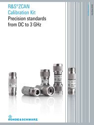
Standard deviation σ in dB<br />
2.5<br />
2<br />
1.5<br />
1<br />
0.5<br />
0<br />
10 2<br />
Standard deviation σ of spectrum emission mask measurement as a function of sweep time (Tsweep)<br />
Transmit modulation<br />
Composite EVM test case 6.7.1<br />
Measurement range 1.0 % to 25 %<br />
Inherent EVM < 1.9 %<br />
Measurement uncertainty test models 1 to 5<br />
P > –40 dBm<br />
<strong>Rohde</strong> & <strong>Schwarz</strong> R&S <strong>®</strong> <strong>FSL</strong> <strong>Spectrum</strong> <strong>Analyzer</strong><br />
T sw eep in ms<br />
< 1 % (σ = 0.3 %)<br />
PMU: < 2.5 %<br />
Peak code domain error power<br />
(PCDEP)<br />
test case 6.7.2<br />
Measurement range –50 dB to 0 dB 0 dB to –50 dB<br />
Inherent PCDEP < −50 dB (σ = 0.95 dB)<br />
Measurement uncertainty<br />
–30 dB < PCDEP < 0.15 dB (σ = 0.05 dB)<br />
PMU: < 1.0 dB<br />
–40 dB < PCDEP < –30 dB < 0.15 dB (σ = 0.05 dB)<br />
PMU: < 1.0 dB<br />
–50 dB < PCDEP < –40 dB < 0.15 dB (σ = 0.05 dB)<br />
PMU: < 1.0 dB<br />
–60 dB < PCDEP < –50 dB < 0.15 dB (σ = 0.05 dB)<br />
PMU:
R&S <strong>®</strong> <strong>FSL</strong>-K82 application firmware<br />
for CDMA2000 <strong>®</strong> base station measurements<br />
Frequency<br />
Frequency range<br />
Level<br />
RF input<br />
R&S <strong>®</strong> <strong>FSL</strong>3 3 MHz to 3 GHz<br />
R&S <strong>®</strong> <strong>FSL</strong>6 3 MHz to 6 GHz 2<br />
R&S <strong>®</strong> <strong>FSL</strong>18 3 MHz to 18 GHz 2<br />
Level range RF input −60 dBm to +30 dBm<br />
Level setting auto, manual<br />
Signal acquisition<br />
Version 10.00, February 2010<br />
Supported standards CDMA2000 <strong>®</strong> BTS<br />
IS-95 BTS<br />
Capture length 2 to 12 power control groups<br />
Sweep time<br />
spectrum mask max. 16000 s, auto<br />
ACPR (adjacent channel power ratio) max. 16000 s<br />
Sweep count 1 to 32767<br />
Trigger modes RF input free run, external<br />
Measurement parameters<br />
Frequency band<br />
predefined bands band classes 0 to 17<br />
unspecified limits can be user-specified<br />
Link mode downlink (DL)<br />
Modulation detection BPSK, QPSK, 8PSK, 16QAM<br />
Predefined channel table code domain analyzer The predefined channel table allows the<br />
complete channel setup of the user signal<br />
for the code domain analyzer.<br />
<strong>Spectrum</strong> emission mask<br />
standard in line with band classes 0 to 17<br />
user The spectrum emission mask<br />
measurement is performed based on<br />
either a manual user setting or a userspecified<br />
XML file.<br />
Result display<br />
Result summary min./mean/current/max. values<br />
Code domain power clear write, max. hold, min. hold, average,<br />
view<br />
Peak code domain error clear write, max. hold, min. hold, average,<br />
view<br />
Power versus power control group clear write, max. hold, min. hold, average,<br />
view<br />
2 All the values specified for R&S <strong>®</strong> <strong>FSL</strong>-K82 in this data <strong>sheet</strong> are valid up to 3 GHz.<br />
global results:<br />
carrier frequency error (reading in Hz and<br />
ppm), chip rate error, trigger to frame,<br />
number of active channels<br />
results for selected power control group:<br />
total power, pilot power, rho, composite<br />
EVM, I/Q imbalance, I/Q offset<br />
results for selected power control group:<br />
absolute power, relative power, symbol<br />
EVM, modulation type, timing offset,<br />
phase offset<br />
code domain power versus channel<br />
code domain error power versus channel<br />
peak code domain error power versus<br />
power control group<br />
power versus power control group for<br />
selected channel<br />
<strong>Rohde</strong> & <strong>Schwarz</strong> R&S <strong>®</strong> <strong>FSL</strong> <strong>Spectrum</strong> <strong>Analyzer</strong> 23
Version 10.00, February 2010<br />
Channel table clear write, max. hold, min. hold, average,<br />
view<br />
24<br />
<strong>Rohde</strong> & <strong>Schwarz</strong> R&S <strong>®</strong> <strong>FSL</strong> <strong>Spectrum</strong> <strong>Analyzer</strong><br />
numeric result table for all channels<br />
including the following readings per<br />
channel:<br />
channel type, channel number, spreading<br />
factor, symbol rate, radio configuration,<br />
state, absolute power, relative power,<br />
timing offset, phase offset<br />
EVM versus power control group<br />
Composite EVM clear write, max. hold, min. hold, average,<br />
view<br />
EVM versus symbol clear write, max. hold, min. hold, average, EVM versus symbol for selected channel<br />
view<br />
and power control group<br />
Power versus symbol clear write, max. hold, min. hold, average, power versus symbol for selected channel<br />
view<br />
and power control group<br />
Channel constellation clear write constellation diagram for selected channel<br />
and power control group<br />
Composite constellation clear write constellation diagram for composite signal<br />
Bit stream clear write bit stream for selected channel and power<br />
control group<br />
Output power clear write, max. hold, min. hold, average, integrated signal power over channel<br />
view, blank<br />
bandwidth<br />
Adjacent channel power<br />
clear write, max. hold, min. hold, average, absolute and relative adjacent channel<br />
Multicarrier adjacent channel power view, blank<br />
power<br />
<strong>Spectrum</strong> emission mask clear write, max. hold, min. hold, average, spectrum mask limit check<br />
view, blank<br />
peak list evaluation<br />
Occupied bandwidth clear write, max. hold, min. hold, average, occupied bandwidth measured in<br />
view, blank<br />
frequency domain<br />
CCDF clear write, view, blank CCDF<br />
Measurement specification (nominal)<br />
Composite EVM<br />
Measurement range 1.7 % to 25 %<br />
Inherent EVM < 1.7 %<br />
Measurement uncertainty<br />
Code domain power<br />
< 0.7 % of reading<br />
Measurement range –60 dBm + 10 dBm<br />
Level uncertainty, total power < 0.7 dB<br />
Level uncertainty, pilot power < 0.7 dB<br />
Level uncertainty, channel power,<br />
absolute<br />
< 0.7 dB<br />
Level uncertainty, channel power, relative<br />
Frequency error measurement<br />
< 0.2 dB<br />
Lock range ±1 kHz<br />
Measurement uncertainty<br />
Peak code domain error<br />
4 Hz + reference frequency uncertainty<br />
Measurement range 0 dB to –50 dB<br />
Inherent PCDE<br />
Trigger to frame<br />
–50 dB<br />
Measurement range < 100 µs<br />
Accuracy<br />
Rho<br />
relative ±110 ns<br />
Measurement uncertainty 0.9 to 1.0 ±5 × 10 –4<br />
Occupied bandwidth<br />
Measurement uncertainty<br />
<strong>Spectrum</strong> emission mask<br />
99 % power bandwidth, span 4.2 MHz ±38 kHz<br />
Dynamic range Ptotal > –20 dBm, ∆f = 750 kHz 60 dB<br />
Level uncertainty<br />
Adjacent channel leakage ratio<br />
0.5 dB<br />
Dynamic range Ptotal > –20 dBm 60 dB<br />
Level uncertainty 0.5 dB
R&S <strong>®</strong> <strong>FSL</strong>-K84 1xEV-DO base station measurement<br />
Frequency<br />
Frequency range<br />
Level<br />
RF input<br />
R&S <strong>®</strong> <strong>FSL</strong>3 3 MHz to 3 GHz<br />
R&S <strong>®</strong> <strong>FSL</strong>6 3 MHz to 6 GHz 3<br />
R&S <strong>®</strong> <strong>FSL</strong>18 3 MHz to 18 GHz 3<br />
Level range RF input −60 dBm to +30 dBm<br />
Level setting auto, manual<br />
Signal acquisition<br />
Version 10.00, February 2010<br />
Supported standards 1xEV-DO Revision 0<br />
1xEV-DO Revision A<br />
Capture length 2 to 12 power control groups<br />
Sweep time spectrum mask<br />
max. 16000 s, auto<br />
adjacent channel power ratio (ACPR) max. 16000 s<br />
Sweep count 1 to 32767<br />
Trigger modes RF input free run, external<br />
Measurement parameters<br />
Frequency band<br />
predefined bands band classes 0 to 17,<br />
unspecified limits can be user-specified<br />
Link mode downlink (DL)<br />
Modulation detection automatic detection of BPSK, QPSK,<br />
8PSK, 16QAM<br />
Predefined channel table code domain analyzer The predefined channel table allows the<br />
complete channel setup of the user signal<br />
for the code domain analyzer<br />
<strong>Spectrum</strong> emission mask<br />
standard in line with band classes 0 to 17<br />
user The spectrum emission mask<br />
measurement is performed based on<br />
either a manual user setting or a userspecified<br />
XML file<br />
Result display<br />
General results clear write, max. hold, min. hold, average,<br />
view<br />
3 All the values specified for R&S <strong>®</strong> <strong>FSL</strong>-K84 in this data <strong>sheet</strong> are valid up to 3 GHz.<br />
global results over all slots:<br />
carrier frequency error (reading in Hz and<br />
ppm), chip rate error, trigger to frame, rho<br />
of pilot channel over all slots, rho of MAC<br />
channel over all slots, rho of data channel<br />
over all slots, rho overall-1 (halfslot<br />
boundary), rho overall-2 (quarterslot<br />
boundary)<br />
results for selected slot:<br />
total power, pilot power, MAC power, data<br />
power, preamble power, rho, composite<br />
EVM<br />
<strong>Rohde</strong> & <strong>Schwarz</strong> R&S <strong>®</strong> <strong>FSL</strong> <strong>Spectrum</strong> <strong>Analyzer</strong> 25
Version 10.00, February 2010<br />
Channel results clear write, max. hold, min. hold, average,<br />
view<br />
26<br />
<strong>Rohde</strong> & <strong>Schwarz</strong> R&S <strong>®</strong> <strong>FSL</strong> <strong>Spectrum</strong> <strong>Analyzer</strong><br />
results for pilot channel:<br />
absolute power, peak code domain error,<br />
I/Q imbalance, IQ offset<br />
Code domain power clear write, max. hold, min. hold, average,<br />
results for selected channel:<br />
symbol rate, timing offset, spreading<br />
factor, symbol EVM (reading in % RMS<br />
and % peak), modulation type, timing<br />
offset, phase offset, absolute channel<br />
power, relative channel power<br />
code domain power versus channel<br />
view<br />
code domain error power versus channel<br />
Peak code domain error clear write, max. hold, min. hold, average,<br />
view<br />
peak code domain error power versus slot<br />
Channel table clear write, max. hold, min. hold, average, numeric result table for all active channels<br />
view<br />
including the following readings per<br />
channel:<br />
channel type, channel number, spreading<br />
factor, symbol rate, modulation type,<br />
absolute power, relative power, timing<br />
offset, phase offset<br />
Composite EVM clear write, max. hold, min. hold, average,<br />
view<br />
EVM versus slot<br />
EVM versus symbol clear write, max. hold, min. hold, average, EVM versus symbol for selected channel<br />
view<br />
and slot<br />
Power versus symbol clear write, max. hold, min. hold, average, power versus symbol for selected channel<br />
view<br />
and slot<br />
Channel constellation clear write constellation diagram for selected channel<br />
and slot<br />
Composite constellation clear write constellation diagram for composite signal<br />
Bit stream clear write bit stream for selected channel and slot<br />
Output power clear write, max. hold, min. hold, average, integrated signal power over channel<br />
view, blank<br />
bandwidth<br />
Adjacent channel power<br />
clear write, max. hold, min. hold, average, absolute and relative adjacent channel<br />
Multicarrier adjacent channel power view, blank<br />
power<br />
<strong>Spectrum</strong> emission mask clear write, max. hold, min. hold, average, spectrum mask limit check<br />
view, blank<br />
peak list evaluation<br />
Occupied bandwidth clear write, max. hold, min. hold, average, occupied bandwidth measured in<br />
view, blank<br />
frequency domain<br />
CCDF clear write, view, blank CCDF<br />
Power versus time clear write, max. hold, min. hold, average, check averaged halfslots against a limit<br />
view, blank<br />
mask in time domain; check separate<br />
limits for full slots and idle slots<br />
Measurement specification (nominal)<br />
Composite EVM<br />
Measurement range 1.7 % to 25 %<br />
Inherent EVM < 1.7 %<br />
Measurement uncertainty<br />
Code domain power<br />
< 0.7 %<br />
Measurement range –60 dBm to +10 dBm<br />
Level uncertainty, total power < 0.7 dB<br />
Level uncertainty, pilot power < 0.7 dB<br />
Level uncertainty, channel power<br />
absolute < 0.7 dB<br />
Frequency error measurement<br />
relative < 0.2 dB<br />
Lock range ±7 kHz<br />
Measurement uncertainty<br />
Peak code domain error<br />
4 Hz + reference frequency uncertainty<br />
Measurement range 0 dB to –53 dB<br />
Inherent PCDE<br />
pilot –50 dB<br />
MAC –47 dB<br />
data –53 dB<br />
preamble –50 dB
Trigger to frame<br />
Measurement range < 100 µs<br />
Accuracy relative ±110 ns<br />
Rho<br />
Measurement uncertainty 0.9 to 1.0 ±5 × 10 –4<br />
Occupied bandwidth<br />
Measurement uncertainty 99 % power bandwidth, span 4.2 MHz ±38 kHz<br />
<strong>Spectrum</strong> emission mask<br />
Dynamic range Ptotal > –20 dBm, ∆f = 750 kHz 60 dB<br />
Level uncertainty < 0.5 dB<br />
Adjacent channel leakage ratio<br />
Dynamic range Ptotal > –20 dBm 60 dB<br />
Level uncertainty < 0.5 dB<br />
Version 10.00, February 2010<br />
<strong>Rohde</strong> & <strong>Schwarz</strong> R&S <strong>®</strong> <strong>FSL</strong> <strong>Spectrum</strong> <strong>Analyzer</strong> 27
Version 10.00, February 2010<br />
R&S <strong>®</strong> <strong>FSL</strong>-K91 WLAN IEEE 802.11a/b/g/j OFDM analysis<br />
R&S <strong>®</strong> <strong>FSL</strong>-K91n WLAN IEEE 802.11n OFDM analysis<br />
The specifications of the R&S <strong>®</strong> <strong>FSL</strong>-K91 and R&S <strong>®</strong> <strong>FSL</strong>-K91n options are based on the data <strong>sheet</strong> of the R&S <strong>®</strong> <strong>FSL</strong> spectrum analyzer.<br />
Specifications apply under the following conditions: 30 minutes warm-up time at ambient temperature, specified environmental<br />
conditions met, calibration cycle adhered to, and all internal automatic adjustments performed. "Typical values" are designated with<br />
the abbreviation "typ." These values are verified during the final test but are not assured by <strong>Rohde</strong> & <strong>Schwarz</strong>. "Nominal values" are<br />
design parameters that are not assured by <strong>Rohde</strong> & <strong>Schwarz</strong>. These values are verified during product development but are not<br />
specifically tested during production.<br />
OFDM analysis<br />
(IEEE 802.11a, IEEE 802.11g OFDM, IEEE 802.11j, IEEE 802.11n)<br />
Frequency<br />
Frequency range<br />
RF input<br />
Frequency setting<br />
Level<br />
28<br />
<strong>Rohde</strong> & <strong>Schwarz</strong> R&S <strong>®</strong> <strong>FSL</strong> <strong>Spectrum</strong> <strong>Analyzer</strong><br />
R&S <strong>®</strong> <strong>FSL</strong>3 50 MHz 4 to 3 GHz<br />
R&S <strong>®</strong> <strong>FSL</strong>6 50 MHz 4 to 6 GHz<br />
R&S <strong>®</strong> <strong>FSL</strong>18 50 MHz 4 to 18 GHz (overrange 20 GHz)<br />
frequency<br />
channel number<br />
Level range RF input up to +30 dBm<br />
Level setting<br />
autorange<br />
manual<br />
Signal acquisition<br />
Supported standards IEEE 802.11a, IEEE 802.11g (OFDM),<br />
IEEE 802.11n (20 MHz), IEEE 802.11j<br />
(10 MHz), IEEE 802.11j (20 MHz)<br />
Modulation format BPSK, QPSK, 16QAM, 64QAM<br />
Demodulator setting auto, manual with/without test of signal<br />
field<br />
Capture length<br />
continuous<br />
IEEE 802.11a, j 24 µs to 15 ms<br />
IEEE 802.11g, n 24 µs to 11.9 ms<br />
Number of bursts that can be analyzed manual 1 to 10922<br />
Result length<br />
PVT, spectrum FFT, CCDF capture length, 1 to 10922 bursts or gate<br />
length<br />
EVM versus symbol and versus carrier,<br />
constellation versus symbol/versus carrier<br />
spectrum flatness, bit stream, signal field<br />
capture length, 1 to 10922 bursts<br />
Burst length<br />
automatic detection of number of data<br />
symbols<br />
1 to 1366 data symbols<br />
manual 1 to 1366 data symbols<br />
Triggering free run, IF power, external<br />
4 1 MHz to 50 MHz with restricted functionality depending on bandwidth (power trigger, auto level, IF overload).
Result display<br />
Result list min./mean/max. values<br />
Power versus time<br />
EVM<br />
Error versus preamble<br />
<strong>Spectrum</strong><br />
Constellation<br />
Statistics<br />
Limit check values in line with standard<br />
Adjustable parameters<br />
Pilot tracking<br />
Channel estimation<br />
Measurement uncertainty (nominal) 5<br />
Version 10.00, February 2010<br />
EVM all carriers<br />
EVM pilots<br />
EVM payload<br />
I/Q offset<br />
gain imbalance<br />
quadrature error<br />
center frequency error<br />
symbol clock error<br />
mean burst power<br />
crest factor<br />
full burst<br />
rising/falling edge<br />
EVM versus symbol<br />
EVM versus carrier<br />
frequency error versus preamble<br />
phase error versus preamble<br />
spectrum mask (IEEE & ETSI),<br />
ACP (IEEE 802.11j: abs./rel.), spectrum<br />
FFT<br />
spectrum flatness<br />
constellation diagram<br />
constellation versus carrier<br />
bit stream<br />
signal field<br />
CCDF<br />
result list<br />
EVM<br />
spectrum mask<br />
ACP<br />
phase ON/OFF<br />
timing ON/OFF<br />
level ON/OFF<br />
data<br />
preamble<br />
Residual EVM<br />
level −23 dBm to +15 dBm,<br />
average of 20 bursts<br />
input RF, f = 2.4 GHz/5 GHz<br />
IEEE 802.11a/g/j signal IEEE 802.11n signal 20 MHz<br />
channel estimation =<br />
preamble<br />
–37 dB/–35 dB –36 dB/–33 dB<br />
Frequency error<br />
channel estimation = data –40 dB/–38 dB –40 dB/–36 dB<br />
Lock range 40 ppm<br />
Uncertainty 1 Hz + reference frequency uncertainty<br />
Level uncertainty<br />
test of spectrum mask<br />
output power<br />
0.2 dB<br />
f < 3 GHz 0.5 dB<br />
3 GHz ≤ f ≤ 6 GHz 0.8 dB<br />
ACPR 0.5 dB<br />
<strong>Spectrum</strong> flatness 0.5 dB<br />
5 Valid for R&S <strong>®</strong> <strong>FSL</strong>3 without tracking generator: serial number ≥ 100838, R&S <strong>®</strong> <strong>FSL</strong>6 without tracking generator: serial number ≥ 100675,<br />
R&S <strong>®</strong> <strong>FSL</strong>3 with tracking generator: serial number ≥ 100704, R&S <strong>®</strong> <strong>FSL</strong>6 with tracking generator: serial number ≥ 100605.<br />
<strong>Rohde</strong> & <strong>Schwarz</strong> R&S <strong>®</strong> <strong>FSL</strong> <strong>Spectrum</strong> <strong>Analyzer</strong> 29
Version 10.00, February 2010<br />
DSSS/CCK/PBCC analysis (IEEE 802.11b, IEEE 802.11g CCK)<br />
Frequency<br />
Frequency range<br />
RF input<br />
Frequency setting<br />
Level<br />
30<br />
<strong>Rohde</strong> & <strong>Schwarz</strong> R&S <strong>®</strong> <strong>FSL</strong> <strong>Spectrum</strong> <strong>Analyzer</strong><br />
R&S <strong>®</strong> <strong>FSL</strong>3 50 MHz 6 to 3 GHz<br />
R&S <strong>®</strong> <strong>FSL</strong>6 50 MHz 6 to 6 GHz<br />
R&S <strong>®</strong> <strong>FSL</strong>18 50 MHz 6 to 18 GHz (overrange 20 GHz)<br />
frequency<br />
channel number<br />
Level range RF input up to +30 dBm<br />
Level setting<br />
autorange<br />
manual<br />
Signal acquisition<br />
Supported standards IEEE 802.11b, IEEE 802.11g (CCK)<br />
Modulation format DBPSK, DQPSK, CCK,<br />
short PLCP, long PLCP<br />
5.5 Mbps, 11 Mbps PBCC<br />
Demodulator setting<br />
auto<br />
manual with/without test of signal field<br />
Capture length continuous 24 µs to 11.9 ms<br />
Number of bursts that can be analyzed manual 1 to 10922<br />
Result length<br />
PVT, spectrum FFT, CCDF capture length, 1 to 10922 bursts or gate<br />
length<br />
EVM versus symbol and versus carrier<br />
constellation versus symbol<br />
bit stream<br />
PLCP header<br />
capture length, 1 to 10922 bursts<br />
Burst length<br />
automatic detection of number of data<br />
symbols<br />
1 to 4095 bytes<br />
manual 1 to 4095 bytes<br />
Triggering free run, IF power, external<br />
6 1 MHz to 50 MHz with restricted functionality depending on bandwidth (power trigger, auto level, IF overload).
Result display<br />
Version 10.00, February 2010<br />
Result list<br />
min./mean/max. values peak vector error<br />
min./mean/max. values burst EVM<br />
I/Q offset<br />
gain imbalance<br />
quadrature error<br />
center frequency error<br />
chip clock error<br />
rise time<br />
fall time<br />
mean burst power<br />
peak burst power<br />
crest factor<br />
Power versus time up ramp/down ramp<br />
EVM EVM versus symbol<br />
Error versus preamble frequency error versus preamble<br />
phase error versus preamble<br />
<strong>Spectrum</strong> spectrum mask, ACPR, spectrum FFT<br />
Constellation constellation diagram<br />
Statistics bit stream<br />
PLCP header<br />
CCDF<br />
Limit check values in line with standard result list, power versus time, EVM,<br />
spectrum mask, ACP<br />
Adjustable parameters<br />
Tracking phase ON/OFF<br />
timing ON/OFF<br />
level ON/OFF<br />
Measurement uncertainty (nominal)<br />
Residual EVM<br />
level −23 dBm to +15 dBm<br />
average of 20 bursts, 11 Mbps CCK with short PLCP, burst EVM<br />
f = 2.442 GHz 1.8 %<br />
Frequency error<br />
Lock range ±0.6 MHz<br />
Uncertainty 1 Hz + reference frequency uncertainty<br />
Level uncertainty<br />
test of spectrum mask<br />
output power<br />
0.2 dB<br />
f < 3 GHz 0.5 dB<br />
3 GHz ≤ f ≤ 6 GHz 0.8 dB<br />
ACPR 0.5 dB<br />
<strong>Rohde</strong> & <strong>Schwarz</strong> R&S <strong>®</strong> <strong>FSL</strong> <strong>Spectrum</strong> <strong>Analyzer</strong> 31
Version 10.00, February 2010<br />
R&S <strong>®</strong> <strong>FSL</strong>-K92 WiMAX IEEE 802.16 OFDM analysis<br />
(IEEE 802.16-2004, IEEE 802.16-2004/Cor1-2005,<br />
IEEE 802.16e-2005, P802.16-Rev2/D3 WiMAX)<br />
The specifications of the R&S <strong>®</strong> <strong>FSL</strong>-K92 WiMAX measurement application are based on the data <strong>sheet</strong> specifications of the R&S <strong>®</strong> <strong>FSL</strong><br />
and R&S <strong>®</strong> ETL signal and spectrum analyzers, have not been checked separately and are not verified during instrument calibration.<br />
The specified level measurement errors do not take into account systematic errors due to reduced signal to noise ratio (S/N).<br />
Specifications apply under the following conditions: 30 minutes warm-up time at ambient temperature, specified environmental<br />
conditions met, calibration cycle adhered to, and all internal automatic adjustments performed.<br />
"Typical values" are designated with the abbreviation "typ.". These values are verified during the final test but are not assured by<br />
<strong>Rohde</strong> & <strong>Schwarz</strong>.<br />
"Nominal values" are design parameters that are not assured by <strong>Rohde</strong> & <strong>Schwarz</strong>. These values are verified during product<br />
development but are not specifically tested during production.<br />
<strong>Data</strong> without tolerance limits is not binding.<br />
Frequency<br />
RF input<br />
R&S <strong>®</strong> <strong>FSL</strong>3 9 kHz 7 to 3 GHz<br />
R&S <strong>®</strong> <strong>FSL</strong>6 9 kHz 7 to 6 GHz<br />
R&S <strong>®</strong> <strong>FSL</strong>18 9 kHz 7 Frequency range<br />
to 18 GHz<br />
R&S <strong>®</strong> ETL 500 kHz 7 to 3 GHz<br />
Frequency setting frequency, channel number<br />
model serial number or lower<br />
R&S <strong>®</strong> <strong>FSL</strong>3 8 100703<br />
R&S <strong>®</strong> <strong>FSL</strong>6 8 100604<br />
R&S <strong>®</strong> <strong>FSL</strong>3 100945<br />
R&S <strong>®</strong> <strong>FSL</strong>6<br />
R&S<br />
100759<br />
<strong>®</strong> 1.44 MHz to 20 MHz<br />
ETL<br />
model serial number or higher<br />
R&S <strong>®</strong> <strong>FSL</strong>3 8 100704<br />
R&S <strong>®</strong> <strong>FSL</strong>6 8 100605<br />
R&S <strong>®</strong> <strong>FSL</strong>3 100946<br />
R&S <strong>®</strong> Sampling rate Fs<br />
1.44 MHz to 32 MHz<br />
<strong>FSL</strong>6 100760<br />
R&S <strong>®</strong> <strong>FSL</strong>18 1.44 MHz to 32 MHz<br />
Level<br />
Level range RF input −60 dBm to +30 dBm<br />
Level setting auto, manual<br />
7 Restricted IF overload, power trigger and auto level functionality depending on carrier frequency and bandwidth at carrier frequencies < 50MHz.<br />
8 With tracking generator.<br />
32<br />
<strong>Rohde</strong> & <strong>Schwarz</strong> R&S <strong>®</strong> <strong>FSL</strong> <strong>Spectrum</strong> <strong>Analyzer</strong>
Signal acquisition<br />
Version 10.00, February 2010<br />
Supported standards IEEE 802.16-2004 OFDM,<br />
IEEE 802.16e-2005 OFDM<br />
P802.16-Rev2/D3 OFDM<br />
Capture length 24 µs to 15.6 ms<br />
Gate length 24 µs to capture length<br />
Number of analyzed bursts 1 to 10922 bursts<br />
power versus time, EVM versus symbol,<br />
EVM versus carrier, frequency error<br />
versus preamble, phase error versus<br />
preamble, constellation versus symbol,<br />
constellation versus carrier, spectrum<br />
flatness, spectrum flatness difference,<br />
group delay, bit stream, burst summary<br />
capture length 9<br />
Result length<br />
FFT spectrum, CCDF capture length or gate length<br />
result summary capture length 9 or 1 to 10922 bursts<br />
Burst length number of data symbols automatically<br />
detected, manually adjustable<br />
1 to 2425<br />
Sweep time<br />
spectrum mask 2.5 ms to 16000 s, auto<br />
adjacent channel power ratio (ACPR) 10 ms to 16000 s<br />
Sweep count 1 to 32767<br />
Trigger modes RF input free run, external, power<br />
Measurement parameters<br />
Frequency band<br />
Sampling rate (Fs),<br />
channel bandwidth (BW)<br />
predefined bands preset combinations of sampling rate (Fs)<br />
and nominal channel bandwidth (BW) in<br />
line with standard<br />
unspecified standard-compliant or user-defined<br />
Fs /BW ratios<br />
If one of the parameters is set, the other is<br />
automatically set as required for the<br />
selected standard. The frequency band<br />
setting is taken into account<br />
Guard period ratio G = Tg/Tb 1/4, 1/8, 1/16, 1/32<br />
Link mode downlink (DL), uplink (UL)<br />
Modulation detection none, first symbol, user, all (auto demod.)<br />
Modulation format BPSK, QPSK, 16QAM, 64QAM<br />
Subchannelization uplink ON/OFF<br />
Subchannel index uplink 1 to 31<br />
UL physical modifier uplink 0 to 255<br />
Pilot tracking<br />
phase ON/OFF<br />
timing ON/OFF<br />
level ON/OFF<br />
Channel estimation preamble, preamble and payload<br />
<strong>Spectrum</strong> emission mask<br />
standard IEEE, ETSI<br />
user-definable The spectrum emission mask is measured<br />
in line with the user setting files<br />
Result display<br />
Result summary min./mean/max. values EVM all carriers, EVM data carriers,<br />
EVM pilot carriers, I/Q offset,<br />
gain imbalance, quadrature error,<br />
frequency error, clock error, burst power,<br />
crest factor, RSSI, RSSI standard<br />
deviation, CINR, CINR standard deviation<br />
Power versus time<br />
full burst<br />
start/end<br />
burst view depending on selected burst<br />
EVM min./mean/max. values<br />
EVM versus symbol<br />
EVM versus carrier<br />
9 Max. 2000 bursts per capture buffer.<br />
<strong>Rohde</strong> & <strong>Schwarz</strong> R&S <strong>®</strong> <strong>FSL</strong> <strong>Spectrum</strong> <strong>Analyzer</strong> 33
Version 10.00, February 2010<br />
Error versus preamble min./mean/max. values<br />
frequency error versus preamble<br />
phase error versus preamble<br />
min./mean/max. values<br />
spectrum flatness<br />
spectrum flatness difference<br />
min./mean/max. values group delay<br />
clear write, max. hold IEEE 10 , ETSI 11 <strong>Spectrum</strong><br />
, user-definable spectrum<br />
mask<br />
clear write, max. hold ACPR (absolute/relative)<br />
clear write FFT spectrum<br />
Constellation<br />
constellation versus symbol<br />
constellation versus carrier<br />
Statistics<br />
CCDF<br />
bit stream<br />
burst summary list<br />
modulation format, burst length in<br />
symbols, power, EVM<br />
Limit check values in line with standard<br />
Measurement uncertainty R&S <strong>®</strong> <strong>FSL</strong> (nominal)<br />
34<br />
<strong>Rohde</strong> & <strong>Schwarz</strong> R&S <strong>®</strong> <strong>FSL</strong> <strong>Spectrum</strong> <strong>Analyzer</strong><br />
result list<br />
EVM, I/Q offset, frequency error, clock<br />
error<br />
spectrum flatness<br />
spectrum flatness difference<br />
spectrum mask<br />
IEEE 12 , ETSI 13 , user-definable<br />
level −30 dBm to +15 dBm, average of 20 bursts<br />
f = 2.4 GHz<br />
DL 15 , UL 16<br />
Residual EVM<br />
channel estimation: preamble and<br />
payload<br />
f = 5 GHz<br />
−40 dB<br />
14<br />
DL 15 , UL 16<br />
channel estimation: preamble and<br />
payload<br />
−37 dB<br />
Frequency error<br />
Max. measurement frequency window DL 15 , UL 16 50 ppm<br />
Uncertainty 1 Hz + R&S <strong>®</strong> <strong>FSL</strong> frequency uncertainty<br />
(see R&S <strong>®</strong> <strong>FSL</strong> reference frequency)<br />
test of spectrum mask like the R&S <strong>®</strong> <strong>FSL</strong><br />
(see R&S <strong>®</strong> <strong>FSL</strong> total measurement<br />
uncertainty)<br />
output power like the R&S <strong>®</strong> <strong>FSL</strong><br />
(see R&S <strong>®</strong> Level uncertainty<br />
<strong>FSL</strong> total measurement<br />
uncertainty)<br />
adjacent channel power ratio (ACPR) like the R&S <strong>®</strong> <strong>FSL</strong><br />
(see R&S <strong>®</strong> <strong>FSL</strong> total measurement<br />
uncertainty)<br />
10<br />
In line with [1] IEEE 802.16-2004.<br />
11<br />
In line with [10] ETSI EN 301 021 V1.6.1 (2003-07).<br />
12<br />
In line with [1] IEEE 802.16-2004.<br />
13<br />
In line with [10] ETSI EN 301 021 V1.6.1 (2003-07).<br />
14 <strong>®</strong> <strong>®</strong><br />
Valid for R&S <strong>FSL</strong>3 with tracking generator serial number ≥ 100704, R&S <strong>FSL</strong>6 with tracking generator serial number ≥ 100605,<br />
R&S <strong>®</strong> <strong>FSL</strong>3 serial number ≥ 100946, R&S <strong>®</strong> <strong>FSL</strong>6 serial number ≥ 100760, R&S <strong>®</strong> <strong>FSL</strong>18.<br />
15<br />
This result is based on the following downlink signal: BW = 10 MHz, Tg/Tb = 1/8. The downlink subframe contains one burst of 30 OFDM symbols<br />
using a QPSK modulation format.<br />
16<br />
This result is based on the following uplink signal: BW = 10 MHz, Tg/Tb = 1/8. The uplink subframe contains one burst of 30 OFDM symbols using a<br />
QPSK modulation format.
Measurement uncertainty R&S <strong>®</strong> ETL 17 (nominal)<br />
Version 10.00, February 2010<br />
Residual EVM<br />
level −30 dBm to +10 dBm, average of 20 bursts<br />
f = 2.4 GHz<br />
DL 15 , UL 16<br />
channel estimation: preamble and<br />
payload<br />
−39 dB<br />
Frequency error<br />
Max. measurement frequency window DL 15 , UL 16 50 ppm<br />
Uncertainty 1 Hz + R&S <strong>®</strong> ETL frequency uncertainty<br />
(see R&S <strong>®</strong> ETL reference frequency)<br />
test of spectrum mask like the R&S <strong>®</strong> ETL (see R&S <strong>®</strong> ETL total<br />
measurement uncertainty)<br />
output power like the R&S <strong>®</strong> ETL (see R&S <strong>®</strong> Level uncertainty<br />
ETL total<br />
measurement uncertainty)<br />
adjacent channel power ratio (ACPR) like the R&S <strong>®</strong> ETL (see R&S <strong>®</strong> ETL total<br />
measurement uncertainty)<br />
17 Valid for R&S <strong>®</strong> ETL fitted with preselector option R&S <strong>®</strong> ETL-B203. The preselector state is off.<br />
<strong>Rohde</strong> & <strong>Schwarz</strong> R&S <strong>®</strong> <strong>FSL</strong> <strong>Spectrum</strong> <strong>Analyzer</strong> 35
Version 10.00, February 2010<br />
R&S <strong>®</strong> <strong>FSL</strong>-K93 WiMAX/WiBro IEEE 802.16 OFDMA SISO<br />
analysis (IEEE 802.16-2004, IEEE 802.16-2004/Cor1-2005,<br />
IEEE 802.16e-2005, P802.16-Rev2/D3 WiMAX and WiBro)<br />
The specifications of the R&S <strong>®</strong> <strong>FSL</strong>-K93 WiMAX measurement application are based on the data <strong>sheet</strong> specifications of the R&S <strong>®</strong> <strong>FSL</strong><br />
and R&S <strong>®</strong> ETL signal and spectrum analyzers, have not been checked separately and are not verified during instrument calibration. The<br />
specified level measurement errors do not take into account systematic errors due to reduced signal to noise ratio (S/N). Specifications<br />
apply under the following conditions: 30 minutes warm-up time at ambient temperature, specified environmental conditions met, calibration<br />
cycle adhered to, and all internal automatic adjustments performed.<br />
"Typical values" are designated with the abbreviation "typ.". These values are verified during the final test but are not assured by<br />
<strong>Rohde</strong> & <strong>Schwarz</strong>.<br />
"Nominal values" are design parameters that are not assured by <strong>Rohde</strong> & <strong>Schwarz</strong>. These values are verified during product<br />
development but are not specifically tested during production.<br />
<strong>Data</strong> without tolerance limits is not binding.<br />
Frequency<br />
Frequency range<br />
Sampling rate Fs<br />
Level<br />
36<br />
<strong>Rohde</strong> & <strong>Schwarz</strong> R&S <strong>®</strong> <strong>FSL</strong> <strong>Spectrum</strong> <strong>Analyzer</strong><br />
RF input<br />
R&S <strong>®</strong> <strong>FSL</strong>3 9 kHz 18 to 3 GHz<br />
R&S <strong>®</strong> <strong>FSL</strong>6 9 kHz 18 to 6 GHz<br />
R&S <strong>®</strong> <strong>FSL</strong>18 9 kHz 18 to 18 GHz<br />
R&S <strong>®</strong> ETL 500 kHz 18 to 3 GHz<br />
model serial number or lower<br />
R&S <strong>®</strong> <strong>FSL</strong>3 19 100703<br />
R&S <strong>®</strong> <strong>FSL</strong>6 19 100604<br />
R&S <strong>®</strong> <strong>FSL</strong>3 100945<br />
R&S <strong>®</strong> <strong>FSL</strong>6<br />
R&S<br />
100759<br />
<strong>®</strong> 1.44 MHz to 20 MHz<br />
ETL<br />
model serial number or higher<br />
R&S <strong>®</strong> <strong>FSL</strong>3 19 100704<br />
R&S <strong>®</strong> <strong>FSL</strong>6 19 100605<br />
R&S <strong>®</strong> <strong>FSL</strong>3 100946<br />
R&S <strong>®</strong> 1.44 MHz to 32 MHz<br />
<strong>FSL</strong>6 100760<br />
R&S <strong>®</strong> <strong>FSL</strong>18 1.44 MHz to 32 MHz<br />
Level range RF input −60 dBm to +30 dBm<br />
Level setting<br />
auto<br />
manual<br />
18 Restricted IF overload, power trigger and auto level functionality depending on carrier frequency and bandwidth at carrier frequencies < 50MHz.<br />
19 With tracking generator.
Signal acquisition<br />
Version 10.00, February 2010<br />
Supported standards<br />
IEEE 802.16-2004 OFDMA SISO<br />
IEEE 802.16-2004/Cor1-2005 OFDMA<br />
SISO<br />
IEEE 802.16e-2005 OFDMA SISO<br />
P802.16-Rev2/D3 OFDMA SISO<br />
IEEE 802.16e-2005 based WiBro<br />
Capture length 24 µs to 15.6 ms<br />
Gate length 24 µs to capture length<br />
Number of analyzed subframes 1 to 10922 subframes<br />
EVM versus symbol, burst summary list,<br />
constellation versus symbol, bit stream<br />
capture length 20<br />
Result length<br />
FFT spectrum, CCDF capture length or gate length<br />
result summary, power versus time, EVM<br />
versus carrier, spectrum flatness,<br />
spectrum flatness difference, group delay,<br />
frequency error versus sample, phase<br />
error versus sample<br />
capture length 20 or<br />
1 to 10922 subframes<br />
Frame length 2 ms to 15 ms<br />
Sweep time<br />
spectrum mask 2.5 ms to 16000 s, auto<br />
adjacent channel power ratio (ACPR) 10 ms to 16000 s<br />
Sweep count 1 to 32767<br />
Trigger modes RF input free run, external, power<br />
Measurement parameters<br />
Frequency band<br />
Sampling rate (Fs),<br />
channel bandwidth (BW)<br />
predefined bands preset combinations of sampling rate (Fs)<br />
and nominal channel bandwidth (BW) in<br />
line with standard<br />
unspecified standard-compliant or user-defined Fs/BW<br />
ratios<br />
If one of the parameters is set, the other is<br />
automatically set as required for the<br />
selected standard. The frequency band<br />
setting is taken into account<br />
Guard period ratio G = Tg/Tb 1/4, 1/8, 1/16, 1/32<br />
NFFT 128, 512, 1024, 2048<br />
Zones<br />
downlink (DL) DL-PUSC, DL-FUSC, DL-AMC 2×3<br />
uplink (UL) UL-PUSC, UL-AMC 2×3<br />
Signal analysis<br />
DL in line with signal DL-MAP (auto demod.),<br />
normal DL-MAP, compressed DL-MAP<br />
DL, UL in line with user-defined frame<br />
configuration<br />
IDcell 0 to 31<br />
Segments DL-PUSC 0, 1, 2<br />
Preamble<br />
preamble mode, auto derived from IDcell and segment setting in<br />
line with standard<br />
preamble mode, user defined by preamble index in line with<br />
standard<br />
Subchannel bitmap used DL-PUSC 6-bit mask allocating subchannel groups to<br />
a segment<br />
Burst modulation format BPSK (pilots only), QPSK, 16QAM,<br />
64QAM<br />
DL, UL phase ON/OFF, timing ON/OFF,<br />
level ON/OFF<br />
use pilots in line with standard 21<br />
Pilot tracking<br />
DL, UL<br />
use detected pilots 22<br />
20 Max. 100 zones/subframes per capture buffer, max. 1000 bursts per capture buffer.<br />
21 The application computes the pilot modulation sequence used for tracking in line with the standard.<br />
22 The application detects the pilot modulation sequence used for tracking the signal to be analyzed.<br />
<strong>Rohde</strong> & <strong>Schwarz</strong> R&S <strong>®</strong> <strong>FSL</strong> <strong>Spectrum</strong> <strong>Analyzer</strong> 37
Version 10.00, February 2010<br />
Channel estimation range<br />
DL<br />
preamble only<br />
preamble and payload<br />
payload only<br />
Zone editor<br />
UL payload only<br />
Zone/segment list<br />
DL, UL zone type, segment, length in symbols,<br />
offset in symbols, PermBase<br />
DL PRBS_ID<br />
Zone/segment map graphical display of frame content defined<br />
by zone/segment list<br />
Max. number of zones/segments per<br />
subframe/frame<br />
Burst editor<br />
26<br />
Burst list<br />
DL modulation, number of subchannels,<br />
number of symbols, offset in subchannels,<br />
offset in symbols, boosting,<br />
burst type:<br />
FCH, DL-MAP, data, restricted HARQ<br />
UL modulation, duration in slots, offset in<br />
subchannels, offset in symbols,<br />
burst type:<br />
data, restricted fast feedback<br />
Burst map graphical display of zone/segment content<br />
defined by burst list<br />
Max. number of bursts per<br />
zone/segment<br />
32<br />
<strong>Spectrum</strong> emission mask<br />
standard IEEE, ETSI, TTA<br />
user-definable The spectrum emission mask is measured<br />
in line with the user setting files.<br />
Result display<br />
Frame configuration auto demodulation burst map in line with decoded signal map<br />
Result summary<br />
analyzed subframes<br />
center frequency error, clock error, TD<br />
min./mean/max. values<br />
power DL preamble, TD power subframe,<br />
TD power zone, crest factor, RSSI, RSSI<br />
standard deviation, CINR, CINR standard<br />
deviation<br />
analyzed zones/segments<br />
BER pilots, EVM data and pilots, EVM<br />
min./mean/max. values<br />
data, EVM pilots, unmodulated subcarrier<br />
error, I/Q offset, gain imbalance,<br />
quadrature error, power DL preamble,<br />
power data and pilots, power data, power<br />
pilots<br />
Power versus time min./mean/max. values<br />
full subframe<br />
rising/falling<br />
EVM min./mean/max. values<br />
EVM versus symbol<br />
EVM versus carrier<br />
Error versus sample min./mean/max. values<br />
frequency error versus sample<br />
phase error versus sample<br />
min./mean/max. values<br />
spectrum flatness<br />
spectrum flatness difference<br />
min./mean/max. values group delay<br />
clear write, max. hold IEEE 23 , ETSI 24 <strong>Spectrum</strong><br />
, TTA, user-definable<br />
spectrum mask<br />
clear write, max. hold ACP (absolute/relative)<br />
clear write FFT spectrum<br />
Constellation constellation diagram versus symbol<br />
23 In line with [1] IEEE 802.16-2004.<br />
24 In line with [10] ETSI EN 301 021 V1.6.1 (2003-07).<br />
38<br />
<strong>Rohde</strong> & <strong>Schwarz</strong> R&S <strong>®</strong> <strong>FSL</strong> <strong>Spectrum</strong> <strong>Analyzer</strong>
Statistics<br />
Limit check values in line with standard<br />
Measurement uncertainty R&S <strong>®</strong> <strong>FSL</strong> (nominal)<br />
Version 10.00, February 2010<br />
CCDF<br />
bit stream<br />
downlink, uplink erroneous pilots are highlighted 25<br />
burst summary:<br />
modulation format, burst area in slots,<br />
power, EVM<br />
result list<br />
center frequency error, clock error,<br />
EVM data and pilots, EVM data, I/Q<br />
offset<br />
spectrum flatness<br />
spectrum flatness difference<br />
spectrum mask<br />
IEEE 26 , ETSI 27 , TTA, user-definable<br />
level −30 dBm to +15 dBm, average of 20 bursts<br />
f = 2.4 GHz<br />
DL 29 , UL 30<br />
Residual EVM<br />
channel estimation: preamble and payload<br />
f = 5 GHz<br />
−40 dB<br />
28<br />
DL 29 , UL 30<br />
channel estimation: payload<br />
−37 dB<br />
Frequency error<br />
Max. measurement frequency window DL 29 , UL 30 30 ppm<br />
Uncertainty 1 Hz + R&S <strong>®</strong> <strong>FSL</strong> frequency uncertainty<br />
(see R&S <strong>®</strong> <strong>FSL</strong> reference frequency)<br />
test of spectrum mask like the R&S <strong>®</strong> <strong>FSL</strong><br />
(see R&S <strong>®</strong> <strong>FSL</strong> total measurement<br />
uncertainty)<br />
output power like the R&S <strong>®</strong> <strong>FSL</strong><br />
(see R&S <strong>®</strong> Level uncertainty<br />
<strong>FSL</strong> total measurement<br />
uncertainty)<br />
ACPR (adjacent channel power ratio) like the R&S <strong>®</strong> <strong>FSL</strong><br />
(see R&S <strong>®</strong> <strong>FSL</strong> total measurement<br />
uncertainty)<br />
25<br />
The detected pilot sequence is compared with the standard-conforming pilot sequence. The standard-conforming pilot sequence depends on the<br />
IDcell, frame number [UL], PRBS_ID [DL], PermBase [DL] user settings.<br />
26<br />
In line with [1] IEEE 802.16-2004.<br />
27<br />
In line with [10] ETSI EN 301 021 V1.6.1 (2003-07).<br />
28 <strong>®</strong> <strong>®</strong><br />
Valid for R&S <strong>FSL</strong>3 with tracking generator serial number ≥ 100704, R&S <strong>FSL</strong>6 with tracking generator serial number ≥ 100605,<br />
R&S <strong>®</strong> <strong>FSL</strong>3 serial number ≥ 100946, R&S <strong>®</strong> <strong>FSL</strong>6 serial number ≥ 100760, R&S <strong>®</strong> <strong>FSL</strong>18.<br />
29<br />
This result is based on the following downlink signal: BW = 8.75 MHz, NFFT = 1024, all 30 subchannels assigned to segment 0.<br />
The segment contains a downlink PUSC zone with one burst of 30 subchannels and 30 OFDMA symbols using a QPSK modulation format.<br />
30<br />
This result is based on the following uplink signal: BW = 8.75 MHz, NFFT = 1024, all 35 subchannels being used.<br />
The uplink PUSC zone contains one burst of 35 subchannels and 30 OFDMA symbols using a QPSK modulation format.<br />
<strong>Rohde</strong> & <strong>Schwarz</strong> R&S <strong>®</strong> <strong>FSL</strong> <strong>Spectrum</strong> <strong>Analyzer</strong> 39
Version 10.00, February 2010<br />
Measurement uncertainty R&S <strong>®</strong> ETL 31 (nominal)<br />
Residual EVM<br />
level −30 dBm to +10 dBm, average of 20 bursts<br />
f = 2.4 GHz<br />
DL 29 , UL 30<br />
channel estimation: preamble and payload −39 dB<br />
Frequency error<br />
Max. measurement frequency window DL 29 , UL 30 30 ppm<br />
Uncertainty 1 Hz + R&S <strong>®</strong> ETL frequency uncertainty<br />
(see R&S <strong>®</strong> ETL reference frequency)<br />
test of spectrum mask like the R&S <strong>®</strong> ETL<br />
(see R&S <strong>®</strong> ETL total measurement<br />
uncertainty)<br />
output power like the R&S <strong>®</strong> ETL<br />
(see R&S <strong>®</strong> Level uncertainty<br />
ETL total measurement<br />
uncertainty)<br />
ACPR (adjacent channel power ratio) like the R&S <strong>®</strong> ETL<br />
(see R&S <strong>®</strong> ETL total measurement<br />
uncertainty)<br />
References<br />
[1] IEEE 802.16-2004, IEEE Standard for Local and Metropolitan Area Networks. October 1, 2004.<br />
[2] IEEE 802.16e-2005 and IEEE 802.16-2004/Cor1-2005. February 28, 2006. Amendment 2: Physical and Medium Access Control<br />
Layers for Combined Fixed and Mobile Operation in Licensed Bands and Corrigendum 1.<br />
[3] P802.16-Rev2/D2 (December 2007) (is a revision of IEEE 802.16-2004 and consolidates material from IEEE 802.16e-2005, IEEE<br />
802.16-2004/Cor1-2005, IEEE 802.16f-2005 and IEEE 802.16g-2007).<br />
[4] P802.16-Rev2/D3 (February 2008) (is a revision of IEEE 802.16-2004 and consolidates material from IEEE 802.16e-2005, IEEE<br />
802.16-2004/Cor1-2005, IEEE 802.16f-2005 and IEEE 802.16g-2007).<br />
[10] ETSI EN 301 021 V1.6.1 (2003-07). Fixed radio systems; point-to-multipoint equipment; time division multiple access (TDMA);<br />
point-to-multipoint digital radio systems in frequency bands in the range 3 GHz to 11 GHz.<br />
31 Valid for R&S <strong>®</strong> ETL fitted with preselector option R&S <strong>®</strong> ETL-B203. The preselector state is off.<br />
40<br />
<strong>Rohde</strong> & <strong>Schwarz</strong> R&S <strong>®</strong> <strong>FSL</strong> <strong>Spectrum</strong> <strong>Analyzer</strong>
Ordering information<br />
Designation Type Order No.<br />
<strong>Spectrum</strong> <strong>Analyzer</strong>, 9 kHz to 3 GHz R&S <strong>®</strong> <strong>FSL</strong>3 1300.2502.03<br />
<strong>Spectrum</strong> <strong>Analyzer</strong>, 9 kHz to 3 GHz,<br />
with tracking generator<br />
R&S <strong>®</strong> <strong>FSL</strong>3 1300.2502.13<br />
<strong>Spectrum</strong> <strong>Analyzer</strong>, 9 kHz to 6 GHz R&S <strong>®</strong> <strong>FSL</strong>6 1300.2502.06<br />
<strong>Spectrum</strong> <strong>Analyzer</strong>, 9 kHz to 6 GHz,<br />
with tracking generator<br />
R&S <strong>®</strong> <strong>FSL</strong>6 1300.2502.16<br />
<strong>Spectrum</strong> <strong>Analyzer</strong>, 9 kHz to 18 GHz R&S <strong>®</strong> <strong>FSL</strong>18 1300.2502.18<br />
<strong>Spectrum</strong> <strong>Analyzer</strong>, 9 kHz to 18 GHz,<br />
with tracking generator<br />
R&S <strong>®</strong> <strong>FSL</strong>18 1300.2502.28<br />
TV <strong>Analyzer</strong>, 500 kHz to 3 GHz,<br />
with tracking generator<br />
R&S <strong>®</strong> Accessories supplied<br />
ETL 2112.0004.13<br />
Power cable, quick start guide and CD-ROM (with operating manual and service manual)<br />
Recommended extras<br />
Printed manual (includes operating<br />
manual and service manual)<br />
1300.3338.32<br />
Options<br />
Version 10.00, February 2010<br />
Designation<br />
Options<br />
Type Order No. Retrofittable Remarks<br />
OCXO Reference Frequency R&S <strong>®</strong> <strong>FSL</strong>-B4 1300.6008.02 yes standard with the<br />
R&S <strong>®</strong> <strong>FSL</strong>18<br />
Additional Interfaces R&S <strong>®</strong> <strong>FSL</strong>-B5 1300.6108.02 yes video out, IF out, noise<br />
source control, AUX port,<br />
R&S <strong>®</strong> NRP-Zxx power<br />
sensor<br />
TV Trigger R&S <strong>®</strong> <strong>FSL</strong>-B6 1300.5901.02 yes<br />
Narrow Resolution Filters R&S <strong>®</strong> <strong>FSL</strong>-B7 1300.5601.02 yes<br />
Gated Sweep R&S <strong>®</strong> <strong>FSL</strong>-B8 1300.5701.02 yes<br />
GPIB Interface R&S <strong>®</strong> <strong>FSL</strong>-B10 1300.6208.02 yes<br />
RF Preamplifier (3/6 GHz) R&S <strong>®</strong> <strong>FSL</strong>-B22 1300.5953.02 yes<br />
DC Power Supply R&S <strong>®</strong> <strong>FSL</strong>-B30 1300.6308.02 yes<br />
NiMH Battery Pack 4.5 Ah R&S <strong>®</strong> <strong>FSL</strong>-B31 1300.6408.02 yes requires R&S <strong>®</strong> <strong>FSL</strong>-B30<br />
Li-Ion Battery Pack 10 Ah with<br />
Battery Charger<br />
R&S <strong>®</strong> ETL-B235 2112.0262.02 yes requires R&S <strong>®</strong> Firmware/Software<br />
<strong>FSL</strong>-B30<br />
AM/FM/φM Measurement Demodulator R&S <strong>®</strong> <strong>FSL</strong>-K7 1301.9246.02<br />
Bluetooth <strong>®</strong> TX Measurements<br />
(1.1 and 2.0 + EDR)<br />
R&S <strong>®</strong> <strong>FSL</strong>-K8 1301.9398.02<br />
Power Sensor Support R&S <strong>®</strong> <strong>FSL</strong>-K9 1301.9530.02 requires R&S <strong>®</strong> <strong>FSL</strong>-B5 or<br />
R&S <strong>®</strong> NRP-Z3/4<br />
Spectrogram Measurements R&S <strong>®</strong> <strong>FSL</strong>-K14 1302.0913.02<br />
Cable TV and TV Measurements R&S <strong>®</strong> <strong>FSL</strong>-K20 1301.9675.02<br />
Application Firmware for Noise Figure and R&S<br />
Gain Measurements<br />
<strong>®</strong> <strong>FSL</strong>-K30 1301.9817.02 requires R&S <strong>®</strong> <strong>FSL</strong>-B5 and<br />
preamplifier<br />
3GPP FDD BTS Application Firmware R&S <strong>®</strong> <strong>FSL</strong>-K72 1302.0620.02<br />
CDMA2000 <strong>®</strong> Base Station Analysis R&S <strong>FSL</strong>-K82 1308.7803.02<br />
1xEV-DO Base Station Measurement R&S <strong>FSL</strong>-K84 1302.0159.02<br />
WLAN IEEE 802.11a/b/g/j Application<br />
Firmware<br />
R&S <strong>®</strong> <strong>FSL</strong>-K91 1302.0094.02<br />
Upgrade of R&S<strong>®</strong><strong>FSL</strong>-K91 to<br />
IEEE 802.11n<br />
R&S <strong>®</strong> <strong>FSL</strong>-K91n 1308.7903.02<br />
WiMAX IEEE 802.16 OFDM Application<br />
Firmware<br />
R&S <strong>®</strong> <strong>FSL</strong>-K92 1302.0236.02<br />
WiMAX IEEE 802.16 OFDM/OFDMA<br />
Application Firmware<br />
R&S <strong>®</strong> <strong>FSL</strong>-K93 1302.0736.02<br />
Upgrade from R&S <strong>®</strong> <strong>FSL</strong>-K92 to<br />
R&S <strong>®</strong> <strong>FSL</strong>-K93<br />
R&S <strong>®</strong> <strong>FSL</strong>-K92U 1302.0307.02<br />
<strong>Rohde</strong> & <strong>Schwarz</strong> R&S <strong>®</strong> <strong>FSL</strong> <strong>Spectrum</strong> <strong>Analyzer</strong> 41
Version 10.00, February 2010<br />
Recommended extras<br />
Designation Type Order No.<br />
19’’ Rackmount Adapter R&S <strong>®</strong> ZZA-S334 1109.4487.00<br />
Soft Carrying Bag R&S <strong>®</strong> <strong>FSL</strong>-Z3 1300.5401.00<br />
Protective Hard Cover R&S <strong>®</strong> EVS-Z6 5201.7760.00<br />
Additional Charger Unit R&S <strong>®</strong> <strong>FSL</strong>-Z4 1300.5430.02<br />
Matching Pad 75 Ω, L section R&S <strong>®</strong> RAM 0358.5414.02<br />
Matching Pad 75 Ω, series resistor 25 Ω R&S <strong>®</strong> RAZ 0358.5714.02<br />
Matching Pad 75 Ω, L section, N to BNC R&S <strong>®</strong> FSH-Z38 1300.7740.02<br />
SWR Bridge, 5 MHz to 3 GHz R&S <strong>®</strong> ZRB2 0373.9017.52<br />
SWR Bridge, 40 kHz to 4 GHz R&S <strong>®</strong> ZRC 1039.9492.52<br />
SWR Bridge, 10 MHz to 3 GHz (incl.<br />
Open, Short, Load calibration standards)<br />
R&S <strong>®</strong> FSH-Z2 1145.5767.02<br />
42<br />
<strong>Rohde</strong> & <strong>Schwarz</strong> R&S <strong>®</strong> <strong>FSL</strong> <strong>Spectrum</strong> <strong>Analyzer</strong>
Power sensors supported by R&S <strong>®</strong> <strong>FSL</strong>-K9<br />
Designation Type Order No.<br />
Average Power Sensor<br />
10 MHz to 8 GHz, 200 mW<br />
R&S <strong>®</strong> NRP-Z11 1138.3004.02<br />
Average Power Sensor<br />
10 MHz to 18 GHz, 200 mW<br />
R&S <strong>®</strong> NRP-Z21 1137.6000.02<br />
Average Power Sensor<br />
10 MHz to 18 GHz, 2 W<br />
R&S <strong>®</strong> NRP-Z22 1137.7506.02<br />
Average Power Sensor<br />
10 MHz to 18 GHz, 15 W<br />
R&S <strong>®</strong> NRP-Z23 1137.8002.02<br />
Average Power Sensor<br />
10 MHz to 18 GHz, 30 W<br />
R&S <strong>®</strong> NRP-Z24 1137.8502.02<br />
Power Sensor Module with Power Splitter<br />
DC to 18 GHz, 500 mW<br />
R&S <strong>®</strong> NRP-Z27 1169.4102.02<br />
Power Sensor Module with Power Splitter<br />
DC to 26.5 GHz, 500 mW<br />
R&S <strong>®</strong> NRP-Z37 1169.3206.02<br />
Average Power Sensor<br />
9 kHz to 6 GHz, 200 mW<br />
R&S <strong>®</strong> NRP-Z91 1168.8004.02<br />
Thermal Power Sensor<br />
0 Hz to 18 GHz, 100 mW<br />
R&S <strong>®</strong> NRP-Z51 1138.0005.02<br />
Thermal Power Sensor<br />
0 Hz to 40 GHz, 100 mW<br />
R&S <strong>®</strong> NRP-Z55 1138.2008.02<br />
Wideband Power Sensor<br />
50 MHz to 18 GHz, 100 mW<br />
R&S <strong>®</strong> NRP-Z81 1137.9009.02<br />
Version 10.00, February 2010<br />
<strong>Rohde</strong> & <strong>Schwarz</strong> R&S <strong>®</strong> <strong>FSL</strong> <strong>Spectrum</strong> <strong>Analyzer</strong> 43
Service you can rely on<br />
J Worldwide<br />
J Local and personalized<br />
J Customized and flexible<br />
J Uncompromising quality<br />
J Long-term dependability<br />
About <strong>Rohde</strong> & <strong>Schwarz</strong><br />
<strong>Rohde</strong> & <strong>Schwarz</strong> is an independent group of companies<br />
specializing in electronics. It is a leading supplier of solutions<br />
in the fields of test and measurement, broadcasting,<br />
radiomonitoring and radiolocation, as well as secure<br />
communications. Established more than 75 years ago,<br />
<strong>Rohde</strong> & <strong>Schwarz</strong> has a global presence and a dedicated<br />
service network in over 70 countries. Company headquarters<br />
are in Munich, Germany.<br />
Environmental commitment<br />
❙ Energy-efficient products<br />
❙ Continuous improvement in environmental sustainability<br />
❙ ISO14001-certified environmental management system<br />
Certified Quality System<br />
ISO 9001<br />
<strong>Rohde</strong> & <strong>Schwarz</strong> GmbH & Co. KG<br />
www.rohde-schwarz.com<br />
Regional contact<br />
❙ Europe, Africa, Middle East<br />
+49 89 4129 137 74<br />
customersupport@rohde-schwarz.com<br />
❙ North America<br />
1 888 TEST RSA (1 888 837 87 72)<br />
customer.support@rsa.rohde-schwarz.com<br />
❙ Latin America<br />
+1 410 910 79 88<br />
customersupport.la@rohde-schwarz.com<br />
❙ Asia/Pacific<br />
+65 65 13 04 88<br />
customersupport.asia@rohde-schwarz.com<br />
R&S<strong>®</strong> is a registered trademark of <strong>Rohde</strong> & <strong>Schwarz</strong> GmbH & Co. KG<br />
Trade names are trademarks of the owners | Printed in Germany (as)<br />
PD 0758.2790.22 | Version 10.00 | February 2010 | R&S<strong>®</strong><strong>FSL</strong><br />
Subject to change<br />
© 2008 - 2010 <strong>Rohde</strong> & <strong>Schwarz</strong> GmbH Co. KG | 81671 München, Germany