Size Depressurization and Relief Devices for Pressurized Segments ...
Size Depressurization and Relief Devices for Pressurized Segments ...
Size Depressurization and Relief Devices for Pressurized Segments ...

Create successful ePaper yourself
Turn your PDF publications into a flip-book with our unique Google optimized e-Paper software.
Required in<strong>for</strong>mation prior to relief-calculation iteration<br />
- Description of the fire scenarios (type of fire, duration,<br />
heat fluxes, size)<br />
- <strong>Relief</strong> segment geometry (system volume, area, weight, etc.)<br />
- Ultimate tensile strength at elevated temperature of<br />
materials in the relief section<br />
- Acceptance criteria <strong>for</strong> rupture<br />
Add insulation if required. Calculate the process segment<br />
pressure profile. Use the fire with the largest heat input (kW).<br />
Calculate the wall-temperature profile <strong>for</strong> all pipes <strong>and</strong> equipment.<br />
Use the local fire with the highest heat flux (kW/m 2 ).<br />
Use the temperature profile to calculate the rupture pressure <strong>for</strong><br />
all pipes <strong>and</strong> equipment. Compare with the actual pressure.<br />
Acceptance criteria:<br />
- Pipe rupture pressure<br />
- Equipment rupture pressure<br />
- Released flammable fluid<br />
at rupture<br />
- Time to rupture<br />
- No rupture<br />
Are the<br />
acceptance<br />
criteria <strong>for</strong> rupture<br />
met?<br />
The design of this section fire-relief valve<br />
<strong>and</strong> fire-insulation requirements is finished.<br />
■ Figure 3. Sizing procedure <strong>for</strong> fire-relief valves is similar to that <strong>for</strong> orifices.<br />
pressurization segment meet the acceptance criteria, then<br />
the fire insulation is completed. Go to Step 7 <strong>for</strong> low-temperature<br />
calculation, otherwise go to Step 6 <strong>and</strong> add in insulation.<br />
Alternatively, go back to Step 1 <strong>and</strong> increase the<br />
size of the orifice or increase the flare system capacity.<br />
Step 6: Decide which piping/equipment to fire-insulate.<br />
If any run of piping or piece of equipment does not<br />
meet the acceptance criteria, then add PFP to one or more<br />
of these components. It is recommended to add PFP to<br />
the corrosion-resistant pipe with the largest diameter. But,<br />
if there are pipes that are already insulated <strong>for</strong> reasons<br />
other than PFP, these should be fire-insulated first.<br />
The reasons <strong>for</strong> choosing the pipe with the largest diameter<br />
are it is the most critical with respect to reaction<br />
<strong>for</strong>ces <strong>and</strong> pressure waves when it ruptures, <strong>and</strong> it will require<br />
the largest amount of insulation per length. Large<br />
pipes are also cheaper to paint <strong>and</strong> insulate (per unit area)<br />
than smaller ones. The reason <strong>for</strong> insulating the corrosion-resistant<br />
pipes first is to avoid insulation on metals<br />
that corrode more easily. When partially insulating pipes,<br />
it is preferable to add the covering on an area where the<br />
possibility of a fire is largest <strong>and</strong> where inspection of the<br />
insulation <strong>and</strong> pipe can be per<strong>for</strong>med easily.<br />
Step 7: Calculate the design low-temperature limitation<br />
of the depressurization segment (this is known as<br />
the minimum design-temperature calculation) <strong>and</strong> in<br />
No<br />
Decide which<br />
pipe/equipment<br />
to fire insulate.<br />
the flare-system tail-pipe. This depressurization<br />
calculation should be per<strong>for</strong>med<br />
without fire input to the section.<br />
All planned types of insulation (not<br />
only fire insulation) should be taken<br />
into account. The initial temperature<br />
should be the minimum ambient temperature<br />
or minimum operating temperature,<br />
whichever is lower. The initial<br />
pressure is calculated from a cooldown<br />
of the system down to the start temperature,<br />
prior to depressurization. The<br />
cooldown calculation should be per<strong>for</strong>med<br />
using the trip pressure from the<br />
highest shutdown pressure. The minimum<br />
temperature in the flare tail-pipe<br />
should be calculated with the depressurization<br />
segment as the only source to<br />
the flare system.<br />
Other considerations<br />
Some key ones to note are:<br />
• The loss of bolt pre-tensioning due<br />
to bolt elongation as a result of increasing<br />
temperature is important when<br />
studying flange failure. The piping engineer<br />
should be consulted on this. Flanges<br />
are recommended to be fire-insulated.<br />
• Lines in the flare system having<br />
no flow during a fire depressurization (e.g., downstream<br />
pressure-control <strong>and</strong> pressure-relief valves) are usually<br />
fire-insulated because: they are thin-walled <strong>and</strong> can heat up<br />
rapidly; the depressurization gas flowing in the flare system<br />
does not cool these pipes; <strong>and</strong> the flare system will be<br />
pressurized to a value near its design pressure, at the same<br />
time that the pipe temperature is high.<br />
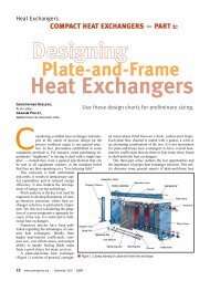
Fire-relief-valve sizing procedure<br />
Sizing of the fire-relief valves (Figure 3) should be<br />
per<strong>for</strong>med with the same minimum requirement as specified<br />
at the beginning of the article. Also, the procedure<br />
closely follows that <strong>for</strong> sizing depressurization orifices,<br />
with the exception, of course, that the pressure will increase<br />
until the relief valve opens. The size of the relief<br />
valve should be such that the minimum relief-rate<br />
equals the liquid boil-off <strong>and</strong> gas-expansion rates. This<br />
avoids a pressure increase above the set pressure of the<br />
relief valve.<br />
A fire-relief valve will usually not protect a pressurized<br />
system against rupture if the gas-filled part of the<br />
system is exposed to fire. The fire-relief valve will normally<br />
protect against rupture if the flame is exposed to<br />
the wetted wall only when the boiling liquid on the inside<br />
keeps the wall temperature at a reasonably low<br />
value. For multicomponent mixtures, the temperature<br />
CEP September 2002 www.cepmagazine.org 43