Size Depressurization and Relief Devices for Pressurized Segments ...
Size Depressurization and Relief Devices for Pressurized Segments ...
Size Depressurization and Relief Devices for Pressurized Segments ...

Create successful ePaper yourself
Turn your PDF publications into a flip-book with our unique Google optimized e-Paper software.
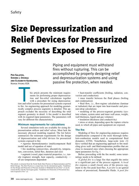
Safety<br />
<strong>Size</strong> <strong>Depressurization</strong> <strong>and</strong><br />
<strong>Relief</strong> <strong>Devices</strong> <strong>for</strong> <strong>Pressurized</strong><br />
<strong>Segments</strong> Exposed to Fire<br />
Per Salater,<br />
Sverre J. Overaa<br />
<strong>and</strong> Elisabeth Kjensjord,<br />
Norsk Hydro ASA<br />
T<br />
his article presents the minimum requirements<br />
<strong>for</strong> per<strong>for</strong>ming proper depressurization<br />
<strong>and</strong> fire-relief calculations together<br />
with a procedure <strong>for</strong> sizing depressurization<br />
<strong>and</strong> relief systems <strong>for</strong> pressurized systems exposed<br />
to fire. An engineering approach <strong>for</strong> modeling geometrically<br />
complex process segments is detailed. This approach<br />
excludes the necessity of describing the total<br />
segment geometry in detail. A fire model is described<br />
with its required input parameters. The parameters will<br />
vary <strong>for</strong> different fire characteristics.<br />
Minimum requirements <strong>for</strong> calculations<br />
Several simulation tools are available <strong>for</strong> sizing depressurization<br />
orifices <strong>and</strong> relief valves. Most lack the<br />
necessary physical modeling required. The list below<br />
summarizes the minimum requirements <strong>for</strong> the design<br />
of depressurization <strong>and</strong> relief devices <strong>for</strong> pressurized<br />
systems exposed to fire:<br />
• rigorous thermodynamics (multicomponent fluid<br />
model <strong>and</strong> use of equation of state)<br />
• fire modeling (emissivities, absorptivity, temperature,<br />
convection, initial flux, duration <strong>and</strong> size)<br />
• segment (vessel, pipe) material properties, i.e., tensile<br />
(rupture) strength, heat capacity, conductivity —<br />
all are temperature-dependent<br />
This article is extracted from the Norsk Hydro Best Practice on <strong>Depressurization</strong> <strong>and</strong> Fire<br />
<strong>Relief</strong> Design. This Best Practice is a major basis <strong>for</strong> the international guide, “Guidelines<br />
<strong>for</strong> the Design <strong>and</strong> Protection of Pressure Systems to Withst<strong>and</strong> Severe Fires” (1) (to be<br />
issued shortly) <strong>and</strong> the Norwegian guide, “Guidelines <strong>for</strong> Protection of <strong>Pressurized</strong> Systems<br />
Exposed to Fire” (2).<br />
38 www.cepmagazine.org September 2002 CEP<br />
Piping <strong>and</strong> equipment must withst<strong>and</strong><br />
fires without rupturing. This can be<br />
accomplished by properly designing relief<br />
<strong>and</strong> depressurization systems <strong>and</strong> using<br />
passive fire protection, when needed.<br />
• heat-transfer coefficients (boiling, radiation, convection<br />
<strong>and</strong> conduction)<br />
• mass transfer between the fluid phases (boiling<br />
<strong>and</strong> condensation)<br />
• fluid flow, i.e., flow-regime calculations (laminar<br />
or turbulent) that are input into heat-transfer <strong>and</strong> pressure-drop<br />
calculations<br />
• modeling of the process-segment geometry (system<br />
volume, system outer <strong>and</strong> inner wall areas, weight,<br />
wall thickness, liquid <strong>and</strong> gas volumes)<br />
• insulation (thickness <strong>and</strong> conductivity)<br />
• stress or strain, depending upon the rupture criteria<br />
used, to which all pipes <strong>and</strong> equipment are exposed.<br />
The fire<br />
Modeling of fires <strong>for</strong> engineering purposes requires<br />
simplifications compared to the more thorough turbulent-combustion<br />
models used in computational fluid<br />
dynamics (CFD). Nonetheless, large-scale tests (3)<br />
have verified that an engineering approach to fire modeling<br />
gives wall- <strong>and</strong> fluid-temperature profiles that are<br />
close to measured ones when choosing the appropriate<br />
input parameters <strong>for</strong> Eq. 1.<br />
Be<strong>for</strong>e proceeding with the fire model, some terminology<br />
needs to be defined:<br />
A global fire is a large fire that engulfs the entire<br />
or a significant part of the process segment. A local<br />
fire exposes a small (local) area of the process segment<br />
to the fire peak heat-flux. A jet fire is an ignited<br />
release of pressurized, flammable fluids. A pool fire
is the combustion of flammable or combustible<br />
fluids spilled <strong>and</strong> retained on a<br />
surface. The ventilation- <strong>and</strong> fuel-controlled<br />
fires are related to the stoichiometric<br />
ratio of air-to-fuel (Figure 1).<br />
Figure 1 is general <strong>for</strong> both a jet <strong>and</strong> a pool<br />
fire; the difference being a higher flux <strong>for</strong> the<br />
jet fire. For a pool fire, the API fire (4) is illustrated<br />
as the lower, dashed line to the right.<br />
Note that in the equation API RP 521 uses, increasing<br />
the area reduces the flux. The dashed<br />
lines represent the average heat flux. However,<br />
when studying the total volume of a fire,<br />
any point on the continuous curve will be<br />
found. A ventilation-controlled fire is to the<br />
left of the peak heat-flux in Figure 1 at a stoichiometry<br />
of < 1. The fuel-controlled fire is to<br />
the right, i.e., the stoichiometry is > 1.<br />
The fire equation<br />
The heat flux absorbed by a segment from a fire, q absorbed<br />
(kW/m 2 ), can be modeled as:<br />
4 4<br />
qabsorbed = κα ( segmentε fireT fire −εsegmentT<br />
segment )+<br />
h× T −T<br />
( gas segment )<br />
The absorbed heat flux will be reduced with increasing<br />
segment temperature, <strong>and</strong> a steady-state segment temperature<br />
will be reached when the heat influx from the fire<br />
equals the heat outflux from the segment.<br />
The view factor, which is not included in Eq. 1, is a<br />
scaling factor <strong>for</strong> the radiative terms. The view factor is<br />
≤ 1.0. It equals 1.0 when the segments that absorb radiation<br />
“see” nothing but an optical, thick flame. Calculation of<br />
view factors is difficult <strong>and</strong> a conservative assumption involves<br />
use of a view factor of 1.0, which results in Eq. 1.<br />
The incident heat flux is calculated by setting α segment =<br />
1.0 <strong>and</strong> disregarding the segment emissivity term. The<br />
“initial incident heat flux” from a fire is<br />
calculated by setting α segment = 1.0 <strong>and</strong><br />
T segment equal to the normal operating temperature<br />
(of the cold segment).<br />
Input to the fire equation<br />
The different terms in the fire equation<br />
are combined to achieve the required initial<br />
heat fluxes. Tables 1, 2 <strong>and</strong> 3 suggest<br />
values to be used. The segment absorptivity<br />
<strong>and</strong> emissivity in Eq. 1 are normally<br />
equal <strong>and</strong> depend upon the nature of the<br />
surface. Typical values are 0.7–0.9. A<br />
value of about 0.8 is typical <strong>for</strong> oxidized<br />
surfaces. The value will change as more<br />
Heat Flux<br />
(1)<br />
Globalventilationcontrolled<br />
1.0<br />
Local fire<br />
Global fuel-controlled<br />
Stochiometric Ratio<br />
Open-fuel-controlled<br />
pool fire<br />
■ Figure 1. The heat flux from a fire <strong>and</strong> its relation to the stoichiometric ratio.<br />
<strong>and</strong> more soot attaches to the surface. For more on absorptivity<br />
<strong>and</strong> emissivity, see Ref. 5.<br />
By combining the suggested highest or lowest typical values<br />
into the fire equation, the heat fluxes toward a cold segment<br />
are found (Table 4 (6)). Typical heat fluxes measured in<br />
large-scale jet fire <strong>and</strong> pool-fire tests are within the maximum<br />
<strong>and</strong> minimum values in Table 4. Norsok (7) recommends<br />
using the initial incident heat fluxes as specified in Table 5.<br />
Sizing procedures<br />
The fire-relief <strong>and</strong> depressurization calculations determine:<br />
• size of the relief valves <strong>and</strong> depressurization orifices<br />
• requirements <strong>for</strong> passive fire protection (PFP)<br />
• size of the pipes downstream from the relief <strong>and</strong> depressurization<br />
valves (if any)<br />
Table 1. Typical flame emissivities <strong>for</strong> global<br />
<strong>and</strong> local fires.<br />
Type of Fire Global Fire Local Fire<br />
εfire εfire Ventilation-controlled pool fire 0.6–0.75 0.7–0.9<br />
Fuel-controlled pool fire 0.6–0.75 0.7–0.8<br />
Jet fire 0.5–0.75 0.6–0.75<br />
Table 2. Typical temperatures <strong>and</strong> convective heat-transfer<br />
coefficients <strong>for</strong> a global fire.<br />
Type of Fire Tfire , °C Tgas , °C h, W/m2 ·K<br />
Ventilation-controlled pool fire 1,000–1,050 850–950 15–30<br />
Fuel-controlled pool fire 950–1,000 800–900 15–30<br />
Jet fire 1,000–1,150 950–1,050 50–125<br />
Table 3. Typical temperatures <strong>and</strong> convective heat-transfer<br />
coefficients <strong>for</strong> a local fire.<br />
Type of Fire Tfire , °C Tgas , °C h, W/m2 ·K<br />
Ventilation-controlled pool fire 1,050–1,125 Equal to T fire 20–30<br />
Fuel-controlled pool fire 1,000–1,050 Equal to T fire 20–30<br />
Jet fire 1,000–1,150 Equal to T fire 100–150<br />
CEP September 2002 www.cepmagazine.org 39
Safety<br />
Table 4. Minimum <strong>and</strong> maximum heat fluxes calculated by Eq. 1 <strong>for</strong> the suggested values of the<br />
input parameters toward a cold segment.<br />
Type of Fire Maximum Minimum Maximum Minimum<br />
Incident Flux, Incident Flux, Absorbed Flux, Absorbed Flux,<br />
kW/m 2 kW/m 2 kW/m 2 kW/m 2<br />
Global jet fire 326 121 306 98<br />
Local jet fire 367 187 347 160<br />
Global fuel-controlled pool fire 138 88 127 65<br />
Local fuel-controlled pool fire 187 124 171 92<br />
Global ventilation-controlled pool fire 158 101 145 75<br />
Local ventilation-controlled pool fire 228 142 208 105<br />
• optimum location of the system’s<br />
sectionalization valves<br />
• minimum design temperature <strong>for</strong><br />
the flare system (if any) <strong>and</strong> <strong>for</strong> the<br />
pressurized segment.<br />
The minimum design temperature may<br />
influence the materials selection of the<br />
system under evaluation. The design usually<br />
begins by considering carbon steel or<br />
stainless steel as the material of construction.<br />
However, temperature calculations<br />
may result in the need to use a different grade of steel, <strong>for</strong><br />
example, replacing a normal carbon steel with one suited<br />
<strong>for</strong> low temperatures.<br />
<strong>Depressurization</strong>-orifice-sizing procedure<br />
Prior to running depressurization calculations, the following<br />
must be established:<br />
• the fire scenarios (jet fire, pool fire, local fire, global<br />
fire, etc.); define the initial heat flux, the duration <strong>and</strong> the<br />
size (extent) of the fire(s)<br />
• the criteria <strong>for</strong> unacceptable rupture, which are usually<br />
one or more of the rupture pressures, the released<br />
flammable/toxic fluid at rupture, <strong>and</strong> the time to rupture<br />
• the time from the start of a fire until depressurization<br />
is initiated<br />
• the physical properties — ultimate tensile strength<br />
(UTS), heat capacity <strong>and</strong> thermal conductivity — at elevated<br />
temperatures (up to 800–1,000°C) <strong>for</strong> the materials of<br />
construction used in the depressurization segments<br />
• the depressurization segment geometry (system volume,<br />
wall area, weight, etc.).<br />
Once the above data are assembled, follow the iterative<br />
procedure in Figure 2. The goal of this depressurization<br />
design is to limit the use of passive fire protection<br />
(PFP) by depressurizing as fast as possible, while remaining<br />
within the discharge capacity of the flare system.<br />
PFP should be avoided due to the risk of the consequences<br />
of undetected corrosion under insulation, <strong>and</strong><br />
the additional installation <strong>and</strong> maintenance costs incurred<br />
by PFP systems.<br />
When designing a new plant, it is not recommended to<br />
consider using the entire flare-system capacity in the cal-<br />
40 www.cepmagazine.org September 2002 CEP<br />
Table 5. Initial incident heat fluxes against "cold" segment (7).<br />
Type of Fire Global Fire Local Fire<br />
(Average load) (Maximum point<br />
load)<br />
Pool fire, enclosed area, ventilation-controlled 130 kW/m2 200 kW/m2 Pool fire (crude), open or enclosed area, 100 kW/m2 150 kW/m2 fuel-controlled<br />
Jet fire 250 kW/m2 culations. This is to allow <strong>for</strong> future tie-ins <strong>and</strong> expected<br />
project growth. However, by increasing the design capacity<br />
of flare system, less PFP will usually be required.<br />
Although a local fire has a higher heat flux than a<br />
global fire, the global fire normally exposes the pressurized<br />
segment to the largest flux of heat energy, due to the<br />
larger area encompassed by a global fire. Hence, the<br />
global-fire parameters determine the rupture pressure. On<br />
the other h<strong>and</strong>, the local fire has the highest heat flux, so<br />
its parameters determine the rupture temperature of the<br />
process segment.<br />
Valves <strong>and</strong> flanges are not accounted <strong>for</strong> in the procedure.<br />
Also, it does not consider the mitigating effects of active fire<br />
protection (such as a deluge). The sizing criteria are set to<br />
avoid an unacceptable rupture that could escalate the fire.<br />
Step 1: Per<strong>for</strong>m an initial estimate of the size of all de-<br />
Nomenclature<br />
h = convection heat-transfer coefficient of air/flame in contact<br />
with segment, W/m 2·K<br />
qabsorbed = absorbed heat flux from the fire, W/m2 Tfire Tgas = flame temperature, K<br />
= temperature of air/flame in contact with segment, K<br />
Tsegment = segment temperature (time-dependent), K<br />
Greek letters:<br />
αsegment = segment absorptivity, dimensionless<br />
εfire = flame emissivity, dimensionless<br />
εsegment = segment emissivity, dimensionless<br />
κ = Stefan-Boltzmann constant = 5.67 × 10⁻⁸ W/m<br />
σaxial = longitudinal stress, MPa<br />
σhoop = hoop stress, MPa<br />
σVon Mises = equivalent stress (Von Mises), MPa<br />
2·K 4
Reduce the<br />
size of the<br />
orifice.<br />
No<br />
(Step 1)<br />
Is the flare system<br />
capacity utilized (when<br />
adding all of the simultaneous<br />
blowdown rates<br />
together)?<br />
Yes<br />
(Step 1)<br />
Is the blowdown<br />
rate less than<br />
maximum<br />
l-dP/dt l<br />
Yes<br />
■ Figure 2. Follow this sizing procedure<br />
to design depressurization orifices.<br />
Acceptance criteria:<br />
- Pipe rupture pressure<br />
- Equipment rupture pressure<br />
- Released fluid at rupture<br />
- Time to rupture<br />
- No rupture<br />
Required in<strong>for</strong>mation prior to blowdown Iteration<br />
- Description of the fire scenarios (type of fire, duration,<br />
heat fluxes, size)<br />
- Blowdown section geometry (system volume, area, weight, etc.)<br />
- Ultimate tensile strength at elevated temperature of<br />
materials in the blowdown section<br />
- Manual or automatic blowdown, i.e., time delay <strong>for</strong> start of<br />
depressurization<br />
- Acceptance criteria <strong>for</strong> rupture<br />
Step 1:<br />
Estimate the size of all orifices <strong>and</strong> calculate the pressure profile <strong>and</strong><br />
flare rates <strong>for</strong> all segments. Use the fire with the largest heat<br />
input (kW). No PFP in this initial iteration.<br />
No<br />
(Step 1) Evaluate to increase the blowdown rate,<br />
preferably <strong>for</strong> the most hazardous blowdown section.<br />
Step 2:<br />
Add insulation if required. Calculate the process segment pressure<br />
profile. Use the fire with the largest heat input (kW).<br />
Tip: Do several calculations with varying amounts of fire insulation.<br />
Step 3:<br />
Calculate the wall-temperature profile <strong>for</strong> all pipes <strong>and</strong> equipment.<br />
Use the local fire with the highest heat flux (kW/m 2 ).<br />
Step 4:<br />
Use the temperature profiles from Step 3 to calculate the rupture pressure<br />
<strong>for</strong> all pipes <strong>and</strong> equipment. Compare with the pressure profile from<br />
Step 2 (Step 1 in the first iteration).<br />
Step 5:<br />
Are the acceptance<br />
criteria <strong>for</strong> rupture<br />
met?<br />
Yes<br />
Step 7:<br />
Calculate the minimum design temperature (low-temperature design<br />
temperature) of the blowdown section <strong>and</strong> the flare system tail pipe.<br />
Is the<br />
minimum design<br />
temperature<br />
acceptable?<br />
Yes<br />
No<br />
No<br />
The design of this section blowdown orifice<br />
<strong>and</strong> fire insulation requirements is finished.<br />
In case of<br />
any of the "ORs"<br />
Step 6:<br />
Decide which pipe/equipment to fire insulate<br />
or<br />
Increase orifice diameter if available<br />
capacity in the flare system, or reduce system<br />
volume by relocation of sectionalization valves<br />
or increase the flare system capacity or change<br />
material quality or increase wall thickness.<br />
Start depressurization at a higher<br />
temperature (or change material).<br />
CEP September 2002 www.cepmagazine.org 41
Safety<br />
pressurization orifices, using the capacity of the flare system<br />
in the calculations. A recommended first estimate is an<br />
orifice diameter that takes the pressure below the “unacceptable”<br />
rupture pressure within the typical time to rupture. The<br />
initial pressure should be the highest normal operating pressure<br />
or an equalization pressure (settle-out pressure) <strong>for</strong> a<br />
compression segment. A global fire should be used. The typical<br />
time-to-rupture can be set at that interval it takes to reach a<br />
600–800°C wall-temperature, depending upon the wall thickness.<br />
A value of 5–10 min is typical <strong>for</strong> a dry wall exposed to<br />
a medium-heat-flux jet-fire, with no depressurization.<br />
One way of improving the safety of the plant is increase<br />
the rate of depressurization, as the hazardous aspects of the<br />
segment increase. The total blowdown rate can be kept unchanged<br />
by increasing the depressurization times of the<br />
less hazardous segments. A segment containing large<br />
amounts of light liquids (e.g., condensate or liquefied<br />
petroleum gas (LPG)), those that will result in boiling-liquid<br />
exp<strong>and</strong>ing-vapor explosions (BLEVEs) are regarded as<br />
a particularly hazardous section. In any case, there may be<br />
limitations on maximum pressure gradients <strong>for</strong> items such<br />
as compressors or gaskets.<br />
Step 2: Add insulation, if required, <strong>and</strong> simulate the<br />
pressure profile during depressurization when exposing<br />
the segment to the global fire. For the first iteration<br />
only, omit this step <strong>and</strong> go to Step 3. A global fire will add<br />
heat to the fire-exposed area without PFP. The initial pressure<br />
in this calculation should be equal to the highest normal<br />
operating or settle-out pressure. Credit <strong>for</strong> insulation<br />
should be given only <strong>for</strong> PFP. Piping <strong>and</strong> equipment with<br />
insulation used <strong>for</strong> purposes other than <strong>for</strong> PFP should be<br />
regarded as uninsulated.<br />
Unrealistic backpressure in the flare system may result<br />
in a too-rapid simulated depressurization. The orifice backpressure<br />
should be based on the time-dependent simultaneous<br />
depressurization rates.<br />
If a depressurization segment is 100% fire-insulated,<br />
then the integrity of the insulation <strong>and</strong> supports usually determines<br />
the maximum allowable depressurization time,<br />
which is typically 30–60 min. Account <strong>for</strong> the integrity of<br />
the insulation by extending the depressurization time <strong>for</strong> a<br />
100% fire-insulated section. The reduced depressurization<br />
rate <strong>for</strong> this section is used to allow <strong>for</strong> the increase of the<br />
rate from a most-hazardous depressurization-section. A reduced<br />
depressurization rate may increase the fire duration,<br />
if a leak in this section is the source of the fire.<br />
Step 3: Simulate the temperature profile <strong>for</strong> all<br />
piping <strong>and</strong> equipment in the depressurization segment<br />
when exposed to the local peak-heat flux. A jet<br />
fire is normally used in these calculations, but the local<br />
load <strong>for</strong> a pool fire should be used if the segment will<br />
not be exposed to a jet fire. “All piping” means all pipes<br />
with different diameters, pressure classes <strong>and</strong>/or material<br />
qualities. The temperature profile <strong>for</strong> one particular<br />
pipe usually is rather insensitive to pressure changes<br />
42 www.cepmagazine.org September 2002 CEP<br />
within a segment, i.e., the temperature profiles from the<br />
first iteration can be kept throughout the whole iteration<br />
procedure. A final update of the temperature profiles<br />
must be per<strong>for</strong>med prior to the last iteration.<br />
Step 4: Calculate whether or not rupture occurs. Determine<br />
the stress or strain that all pipes <strong>and</strong> equipment are<br />
exposed to <strong>for</strong> the temperatures <strong>and</strong> pressures seen during<br />
the depressurization (Calculated in Steps 1 or 2, <strong>and</strong> Step<br />
3) <strong>and</strong> determine whether the segment will rupture.<br />
Two failure (rupture) criteria are often used: the maximum<br />
stress or maximum strain (% elongation). The maximum<br />
stress criterion is usually the UTS. Rupture strain is a matter<br />
of definition. Strain calculations require finite-element modeling<br />
of the system, which is usually not per<strong>for</strong>med during<br />
this step-wise method. Such calculations should be per<strong>for</strong>med<br />
<strong>for</strong> verification purposes during the final design.<br />
The suggested approach is to calculate the stress<br />
from the internal pressure <strong>and</strong> add extra stress (margins)<br />
when calculating the longitudinal stress. The stresses of<br />
importance <strong>for</strong> a pipe are the hoop stress caused by internal<br />
pressure, <strong>and</strong> the longitudinal stress. The longitudinal<br />
stress is the sum of axial stresses due to pressure;<br />
the weight of the pipe, valves, fittings, branch pipes,<br />
etc; stress due to reaction <strong>for</strong>ces exerted on the pipe by<br />
pressure; <strong>and</strong> stress due to thermal elongation of the<br />
pipe. The equivalent stress (von Mises) is the stress to<br />
be compared with the temperature-dependent UTS to<br />
determine whether rupture occurs. The hoop stress,<br />
σ hoop , is equal to:<br />
Pressure × Outer dia.<br />
σhoop =<br />
2 × Wall thickness<br />
The longitudinal stress, σ long , is given by:<br />
σ long = 1/2σ hoop + x (3)<br />
The equivalent stress is given by:<br />
2 2<br />
Von Mises hoop axial hoop axial (4)<br />
σ _ = σ + σ − σ × σ<br />
The term x in Eq. 3 represents all stress except <strong>for</strong> that<br />
set up by the pressure. A piping engineer should be consulted<br />
when determining the value of x.<br />
It is recommended that the UTS by reduced by 20% or<br />
more, depending on the reliability of the UTS data. The<br />
20% is a safety margin. Reduce the wall thickness by accounting<br />
<strong>for</strong> the mill tolerance. It must be assumed that the<br />
lower mill tolerance is delivered. Reduce the strength by<br />
including the weld factor. Again, a piping engineer should<br />
be consulted.<br />
Step 5: Check the rupture pressure against the acceptance<br />
criteria. If all piping <strong>and</strong> equipment in the de-<br />
(2)
Required in<strong>for</strong>mation prior to relief-calculation iteration<br />
- Description of the fire scenarios (type of fire, duration,<br />
heat fluxes, size)<br />
- <strong>Relief</strong> segment geometry (system volume, area, weight, etc.)<br />
- Ultimate tensile strength at elevated temperature of<br />
materials in the relief section<br />
- Acceptance criteria <strong>for</strong> rupture<br />
Add insulation if required. Calculate the process segment<br />
pressure profile. Use the fire with the largest heat input (kW).<br />
Calculate the wall-temperature profile <strong>for</strong> all pipes <strong>and</strong> equipment.<br />
Use the local fire with the highest heat flux (kW/m 2 ).<br />
Use the temperature profile to calculate the rupture pressure <strong>for</strong><br />
all pipes <strong>and</strong> equipment. Compare with the actual pressure.<br />
Acceptance criteria:<br />
- Pipe rupture pressure<br />
- Equipment rupture pressure<br />
- Released flammable fluid<br />
at rupture<br />
- Time to rupture<br />
- No rupture<br />
Are the<br />
acceptance<br />
criteria <strong>for</strong> rupture<br />
met?<br />
The design of this section fire-relief valve<br />
<strong>and</strong> fire-insulation requirements is finished.<br />
■ Figure 3. Sizing procedure <strong>for</strong> fire-relief valves is similar to that <strong>for</strong> orifices.<br />
pressurization segment meet the acceptance criteria, then<br />
the fire insulation is completed. Go to Step 7 <strong>for</strong> low-temperature<br />
calculation, otherwise go to Step 6 <strong>and</strong> add in insulation.<br />
Alternatively, go back to Step 1 <strong>and</strong> increase the<br />
size of the orifice or increase the flare system capacity.<br />
Step 6: Decide which piping/equipment to fire-insulate.<br />
If any run of piping or piece of equipment does not<br />
meet the acceptance criteria, then add PFP to one or more<br />
of these components. It is recommended to add PFP to<br />
the corrosion-resistant pipe with the largest diameter. But,<br />
if there are pipes that are already insulated <strong>for</strong> reasons<br />
other than PFP, these should be fire-insulated first.<br />
The reasons <strong>for</strong> choosing the pipe with the largest diameter<br />
are it is the most critical with respect to reaction<br />
<strong>for</strong>ces <strong>and</strong> pressure waves when it ruptures, <strong>and</strong> it will require<br />
the largest amount of insulation per length. Large<br />
pipes are also cheaper to paint <strong>and</strong> insulate (per unit area)<br />
than smaller ones. The reason <strong>for</strong> insulating the corrosion-resistant<br />
pipes first is to avoid insulation on metals<br />
that corrode more easily. When partially insulating pipes,<br />
it is preferable to add the covering on an area where the<br />
possibility of a fire is largest <strong>and</strong> where inspection of the<br />
insulation <strong>and</strong> pipe can be per<strong>for</strong>med easily.<br />
Step 7: Calculate the design low-temperature limitation<br />
of the depressurization segment (this is known as<br />
the minimum design-temperature calculation) <strong>and</strong> in<br />
No<br />
Decide which<br />
pipe/equipment<br />
to fire insulate.<br />
the flare-system tail-pipe. This depressurization<br />
calculation should be per<strong>for</strong>med<br />
without fire input to the section.<br />
All planned types of insulation (not<br />
only fire insulation) should be taken<br />
into account. The initial temperature<br />
should be the minimum ambient temperature<br />
or minimum operating temperature,<br />
whichever is lower. The initial<br />
pressure is calculated from a cooldown<br />
of the system down to the start temperature,<br />
prior to depressurization. The<br />
cooldown calculation should be per<strong>for</strong>med<br />
using the trip pressure from the<br />
highest shutdown pressure. The minimum<br />
temperature in the flare tail-pipe<br />
should be calculated with the depressurization<br />
segment as the only source to<br />
the flare system.<br />
Other considerations<br />
Some key ones to note are:<br />
• The loss of bolt pre-tensioning due<br />
to bolt elongation as a result of increasing<br />
temperature is important when<br />
studying flange failure. The piping engineer<br />
should be consulted on this. Flanges<br />
are recommended to be fire-insulated.<br />
• Lines in the flare system having<br />
no flow during a fire depressurization (e.g., downstream<br />
pressure-control <strong>and</strong> pressure-relief valves) are usually<br />
fire-insulated because: they are thin-walled <strong>and</strong> can heat up<br />
rapidly; the depressurization gas flowing in the flare system<br />
does not cool these pipes; <strong>and</strong> the flare system will be<br />
pressurized to a value near its design pressure, at the same<br />
time that the pipe temperature is high.<br />
Fire-relief-valve sizing procedure<br />
Sizing of the fire-relief valves (Figure 3) should be<br />
per<strong>for</strong>med with the same minimum requirement as specified<br />
at the beginning of the article. Also, the procedure<br />
closely follows that <strong>for</strong> sizing depressurization orifices,<br />
with the exception, of course, that the pressure will increase<br />
until the relief valve opens. The size of the relief<br />
valve should be such that the minimum relief-rate<br />
equals the liquid boil-off <strong>and</strong> gas-expansion rates. This<br />
avoids a pressure increase above the set pressure of the<br />
relief valve.<br />
A fire-relief valve will usually not protect a pressurized<br />
system against rupture if the gas-filled part of the<br />
system is exposed to fire. The fire-relief valve will normally<br />
protect against rupture if the flame is exposed to<br />
the wetted wall only when the boiling liquid on the inside<br />
keeps the wall temperature at a reasonably low<br />
value. For multicomponent mixtures, the temperature<br />
CEP September 2002 www.cepmagazine.org 43
Safety<br />
Process<br />
Stream<br />
Sectionalization Valve<br />
EV or XV<br />
■ Figure 4. Modeling<br />
the real process segment<br />
as a hypothetical one<br />
simplifies sizing procedures.<br />
To the Flare System<br />
Cooler<br />
PSV<br />
PSV<br />
Scrubber<br />
will increase as the lighter components evaporate, <strong>and</strong><br />
the wall will eventually reach the rupture temperature,<br />
even if it is liquid-filled.<br />
Modeling process segments<br />
Here, we present an approach to modeling complex<br />
depressurization <strong>and</strong> relief segments. The method models<br />
the complete complex geometry by creating one hypothetical<br />
segment that represents the total system volume<br />
<strong>and</strong> heat-transfer areas, <strong>and</strong> several sub-segments that<br />
represent the “real” geometries of the segment.<br />
The hypothetical segment is used <strong>for</strong> calculation of the<br />
system pressure during depressurization or relief. The subsegments<br />
are used <strong>for</strong> calculation of the temperature response<br />
of each piece of piping <strong>and</strong> equipment within a process<br />
segment. The sub-segments are modeled with the<br />
same geometric in<strong>for</strong>mation that is required <strong>for</strong> a wall-temperature-response<br />
calculation — namely, the sub-segment<br />
wall thickness, segment or pipe diameter <strong>and</strong> inside fluid.<br />
44 www.cepmagazine.org September 2002 CEP<br />
D i<br />
Flare System<br />
Antisurge Valve<br />
Blowdown<br />
EV<br />
Length<br />
Compressor<br />
Sectionalization Valve<br />
EV or XV<br />
To the Flare System<br />
Blowdown<br />
Orifice<br />
Blowdown<br />
EV<br />
Process Stream<br />
Flare System<br />
Blowdown<br />
Orifice<br />
PSV = Pressure Safety Valve<br />
EV = Emergency Valve<br />
XV = Sectionalization Valve<br />
Sectionalization valves close<br />
in emergency situations.<br />
Blowdown valves open in<br />
fire situations.<br />
Sectionalization Valve<br />
EV or XV<br />
Process Stream<br />
The real geometry of any type of process segment (e.g., the above system drawn in continous<br />
lines) is trans<strong>for</strong>med into a hypothetical cylindrical vessel (the vessel below in continuous line).<br />
The hypothetical vessel is used in calculation of system pressure during depressurization <strong>and</strong> relief.<br />
The diameter <strong>and</strong> length are increased until the volume equals the volume of the original system<br />
(use the dominating diameter of the original system). The liquid level is adjusted to match the<br />
liquid volume of the original system, "Add or subtract" wet <strong>and</strong> dry areas to match the wet <strong>and</strong><br />
dry area of the original system. Set a wall thickness equal to the dominating wall thickness of<br />
the original system <strong>and</strong> adjust the weight until the weight matches the original sysem weight.<br />
Hence, we have a hypothetical segment where the system area <strong>and</strong> weight do not fit the<br />
hypothetical cylinder, but do fit the original system.<br />
Hypothetical segment used <strong>for</strong> system pressure<br />
The hypothetical segment is modeled with the real system<br />
volume, system outer-area, with <strong>and</strong> without PFP, system<br />
inside-area in contact with the gas, system inside-area<br />
in contact with the liquid, <strong>and</strong> system weight (of piping<br />
<strong>and</strong> equipment).<br />
The hypothetical segment is modeled as a cylinder.<br />
This shape is specified with a diameter equal to the mostdominating<br />
(volume) diameter of any item of piping or<br />
equipment in the original segment. The associated wall<br />
thickness <strong>for</strong> this diameter should be used. The length of<br />
the cylinder is set such that its volume equals the volume<br />
of the original segment. The liquid level is adjusted to obtain<br />
the actual liquid volume. The hypothetical cylinder<br />
now represents the correct system volume. However, the<br />
outer area of this cylinder must be corrected to the realsystem<br />
outer area by subtracting or adding gas <strong>and</strong> liquid<br />
area to the segment. There<strong>for</strong>e, heat transfer with the surroundings<br />
(fire, ambient air) will be modeled over the real
area. The system outside <strong>and</strong> inside areas may be different<br />
<strong>for</strong> a high-pressure system (typically, 100–150 bar), with<br />
large amount of small-diameter piping (usually, 3 in. <strong>and</strong><br />
below), <strong>and</strong> should similarly be corrected to the real system<br />
inside area. This effect is largest <strong>for</strong> pipes with a corrosion<br />
allowance, that is, those made of carbon steel, generally.<br />
The dominating (by weight) metal quality should<br />
be specified.<br />
Unique geometry used <strong>for</strong> wall-temperature calculations.<br />
The temperature response of a pipe or piece of<br />
equipment exposed to fire depends upon the metal wall<br />
thickness, metal properties (e.g., heat capacity <strong>and</strong> conductivity)<br />
<strong>and</strong> the thermal mass of the inside fluid. Each<br />
combination of these must be calculated individually to<br />
determine the possible different wall-temperature responses<br />
of the system.<br />
The exact inside <strong>and</strong> outside diameters (I.D.s <strong>and</strong><br />
O.D.s) should be used. The I.D. will determine the thermal<br />
mass of the inside fluid. The O.D. will enable calculation<br />
of the fire-exposed area. Any length can be used,<br />
since the sub-segment volume <strong>and</strong> mass are proportional<br />
to the length. The actual thickness, minus a corrosion allowance,<br />
should be used. The actual thickness is the<br />
nominal wall thickness, minus the allowable tolerance of<br />
the pipe thickness (the mill tolerance). The corrosion allowance<br />
should be accounted <strong>for</strong> after reduction by the<br />
mill tolerance. Typical values of the mill tolerance are<br />
1.5–3 mm <strong>for</strong> carbon steel, with the larger value being<br />
Literature Cited<br />
1. Institute of Petroleum, “Guidelines <strong>for</strong> the Design <strong>and</strong> Protection<br />
of <strong>Pressurized</strong> Systems to Withst<strong>and</strong> Severe Fires,” Inst. of<br />
Petroleum, U.K. (to be issued shortly).<br />
2. Sc<strong>and</strong>power Risk Management AS, “Guidelines <strong>for</strong> Protection of<br />
Pressurised Systems Exposed to Fire,” Sc<strong>and</strong>power AS, Norway<br />
(www.sc<strong>and</strong>power.com/?CatID=1071) (May 13, 2002).<br />
3. Stange, E., et al., “Determination of Temperatures <strong>and</strong> Flare<br />
Rates During <strong>Depressurization</strong> <strong>and</strong> Fire,” paper presented at 72nd<br />
Annual Gas Processors Association Convention, San Antonio, TX<br />
(1993).<br />
4. American Petroleum Institute, “Guide <strong>for</strong> Pressure-Relieving <strong>and</strong><br />
Depressurizing Systems,” API Recommended Practice (RP) 521,<br />
4th ed., API, Washington, DC (1997).<br />
5. Incropera, F. P., <strong>and</strong> D. P. DeWitt, “Fundamentals of Heat <strong>and</strong><br />
Mass Transfer,” 4th ed., John Wiley, New York (1996).<br />
6. Health <strong>and</strong> Safety Executive, “Joint Industry Project on Blast <strong>and</strong><br />
Fire Engineering of Topside Structures,” OTI 92 596/597/598,<br />
HSE, U.K.,(1991).<br />
7. Norsok St<strong>and</strong>ard, “Technical Safety,” S-001, Rev. 3, (www.nts.no/<br />
norsok) (2000).<br />
Acknowledgment<br />
We would like to thank Erik Odgaard, Jan A. Pappas <strong>and</strong> Geir Johansen<br />
(Norsk Hydro, safety <strong>and</strong> piping discipline) <strong>for</strong> their helpful<br />
discussions.<br />
more common. The mill tolerance is specified on the<br />
pipe data sheet. When this tolerance is not specified by<br />
the pipe supplier, consult a piping engineer.<br />
The correct metal or alloy composition must be used to<br />
obtain the correct material properties (i.e., heat capacity,<br />
conductivity <strong>and</strong> the UTS). If the UTS is not available at<br />
elevated temperatures, a preliminary tensile curve can be<br />
made based on the UTS at 20°C; this is usually available.<br />
When the strength at an elevated temperature is known <strong>for</strong><br />
a material that is close in physical properties (the same<br />
family of materials, such as two different carbon steels),<br />
then the percentage difference in the UTS at 20°C is kept<br />
at all temperatures. That is, the new tensile strength curve<br />
should have the same shape as the known curve. When the<br />
tensile strength at elevated temperatures is not known <strong>for</strong> a<br />
material in the same family, then the percentage difference<br />
between the UTS <strong>and</strong> yield at 20°C is reduced linearly between<br />
20 <strong>and</strong> 1,000°C. The UTS should be released by at<br />
least 30% (not 20%) in such an approximation. When the<br />
UTS is equal to the yield strength in the above calculation,<br />
then the UTS should be set equal to the yield strength at<br />
higher temperatures.<br />
Concluding remarks<br />
We believe that the calculation of longitudinal stress<br />
represents the major challenge when per<strong>for</strong>ming depressurization<br />
<strong>and</strong> fire relief design. Modeling of time-dependent<br />
fire characteristics (the extent <strong>and</strong> heat flux) also represents<br />
a challenge, since the plant layout is usually unknown during<br />
the design stage. Yield <strong>and</strong> UTS data at temperatures<br />
above 400–500°C often do not exist <strong>for</strong> the materials used<br />
in the system. ◆<br />
PER SALATER is a principal engineer in Norsk Hydro ASA (N-0246 Oslo,<br />
Norway; Phone: +47 22 53 76 91; Fax: +47 22 53 95 37; E-mail:<br />
per.salater@hydro.com). He has ten years of experience as a process <strong>and</strong><br />
system engineer <strong>for</strong> Norsk Hydro’s North Sea oil <strong>and</strong> gas facilities. His areas<br />
of expertise are system design, heat-exchanger thermal design <strong>and</strong> design<br />
of depressurization systems. He has with Sverre Overaa co-patented<br />
(PCT/NO99/00123, U.S. Patent 09/673467) a design that eliminates the<br />
flare system <strong>for</strong> oil-<strong>and</strong>-gas processing facilities <strong>and</strong> replaces it with a<br />
blowdown header connected to storage. He holds an MSc in mechanical<br />
engineering from the Norwegian Institute of Technology, Trondheim.<br />
SVERRE J. OVERAA is a principal engineer at Norsk Hydro ASA (Phone: +47 22<br />
53 81 00; Fax: +47 22 53 27 25; E-mail: Sverre.J.Overaa@hydro.com). He is a<br />
member of the GPA Technical Section F Research Committee. Overaa has 18<br />
years of experience as a process <strong>and</strong> systems engineer <strong>for</strong> Norsk Hydro’s<br />
North Sea oil-<strong>and</strong>-gas facilities <strong>and</strong> is currently head of technical systems<br />
<strong>for</strong> the Ormen Lange project under development by Norsk Hydro. His areas<br />
of expertise are simulation, fluid properties <strong>and</strong> system design. He has with<br />
Per Salater co-patented PCT/NO99/00123, U.S. Patent 09/673467.<br />
ELISABETH KJENSJORD is a process engineer with Norsk Hydro ASA (Phone:<br />
+47 22 53 81 00; Fax: +47 22 53 27 25; E-mail: elisabeth.kjensjord@<br />
hydro.com). She is involved in process design of Norsk Hydro’s oil-<strong>and</strong>-gas<br />
facilities <strong>and</strong> is presently engaged in the development of the Grane oil field<br />
located on the Norwegian Continental Shelf in the southern part of the<br />
North Sea. She holds an MSc in chemical engineering from the Norwegian<br />
Univ. of Science <strong>and</strong> Technology.<br />
CEP September 2002 www.cepmagazine.org 45