Manuel technique (pdf, 0.37 MB) - Niko
Manuel technique (pdf, 0.37 MB) - Niko
Manuel technique (pdf, 0.37 MB) - Niko

You also want an ePaper? Increase the reach of your titles
YUMPU automatically turns print PDFs into web optimized ePapers that Google loves.
05-091/05-092/05-093/05-094/05-095<br />
De IR-busdrukknop met identieke adressen: 05-091 / 05-092 / 05-093 / 05-094 / 05-095 (enkel met<br />
4 bedieningsknoppen)<br />
Dit product is een deel van het <strong>Niko</strong>bus-domoticasysteem. Voor een beschrijving van het totaalsysteem verwijzen<br />
wij U naar de <strong>Niko</strong>bus-catalogus en -handleiding of naar www.niko.be.<br />
1. WETTELIJKE WAARSCHUWINGEN<br />
- Lees de volledige handleiding vóór installatie en ingebruikname.<br />
- De installatie dient te worden uitgevoerd door een erkend installateur en met inachtname van de geldende<br />
voorschriften.<br />
- Deze handleiding dient aan de gebruiker te worden overhandigd. Zij moet bij het dossier van de elektrische<br />
installatie worden gevoegd en dient te worden overgedragen aan eventuele nieuwe eigenaars. Bijkomende<br />
exemplaren zijn verkrijgbaar via de <strong>Niko</strong>-website of -supportdienst.<br />
- Bij de installatie dient rekening gehouden te worden met (lijst is niet limitatief):<br />
- de geldende wetten, normen en reglementen;<br />
- de stand van de techniek op het ogenblik van de installatie;<br />
- het feit dat een handleiding alleen algemene bepalingen vermeldt en dient gelezen te worden binnen het<br />
kader van elke specifieke installatie;<br />
- de regels van goed vakmanschap.<br />
- Bij twijfel kan u de supportdienst van <strong>Niko</strong> raadplegen of contact opnemen met een erkend controleorganisme.<br />
Support België: Support Nederland:<br />
tel. + 32 3 760 14 82 tel. + 31 183 64 06 60<br />
website: http://www.niko.be website: http://www.niko.nl<br />
e-mail: support@niko.be e-mail: sales@niko.nl<br />
In geval van defect kan u uw product terugbezorgen aan een erkende <strong>Niko</strong>-groothandel samen met een duidelijke<br />
omschrijving van uw klacht (manier van gebruik, vastgestelde afwijking…).<br />
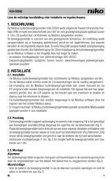
2. BESCHRIJVING<br />
Normaal heeft iedere busdrukknop en IR-busdrukknop een uniek adres. Dit wil zeggen dat iedere busdrukknop<br />
en IR-busdrukknop een verschillende functie kan oproepen. Als IR-busdrukknoppen dezelfde functies<br />
moeten oproepen vanop verschillende plaatsen zonder telkens te programmeren, kan u IR-busdrukknoppen<br />
met hetzelfde adres gebruiken. Op deze manier moet er maar één IR-busdrukknop geprogrammeerd worden.<br />
De overige IR-busdrukknoppen met hetzelfde adres nemen automatisch deze acties over. U bepaalt zelf het<br />
gewenste aantal IR-busdrukknoppen met identiek adres en bestelt ze onder één bestelreferentie (bv.: 05-091).<br />
Wenst u in één project meerdere acties te programmeren en daarbij gebruik te maken van IR-busdrukknoppen<br />
met identiek adres, dan kan u ze groeperen in max. 5 groepen met elk hun bestelreferentie: 05-091, 05-092,<br />
05-093, 05-094 en 05-095.<br />
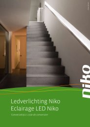
De busdrukknop is een driestandendrukknop: er is steeds een positie boven, de neutrale stand keert steeds<br />
automatisch terug (= geen bediening), met een geïntegreerde infraroodontvanger.<br />
De infraroodontvanger kan bediend worden met de IR-handzender (05-088), de IR-universele afstandsbediening<br />
(05-089) of de IR-Pronto (05-090).<br />
De busdrukknoppen hebben het vertrouwde uiterlijk van de <strong>Niko</strong>bus-schakelaars. In het <strong>Niko</strong>bus-systeem<br />
dienen ze echter niet als schakelaar, wel als informatiezender. Een <strong>Niko</strong>bus-drukknop wordt ingebouwd in een<br />
enkelvoudige standaardinbouwdoos voor schroefbevestiging. Voor montage onder meervoudige afdekplaten zijn<br />
geen bijkomende inbouwdozen noodzakelijk. De <strong>Niko</strong>bus-drukknoppen zijn uitbreidbaar zonder extra kap- of<br />
breekwerk. De <strong>Niko</strong>bus-drukknop vereist geen enkele instelling of afregeling.<br />
De functies van de busdrukknoppen worden niet bepaald door de busdrukknop zelf, maar door de instellingen<br />
die u maakt op de module. Tijdens het instellen van het systeem worden de functies van de busdrukknoppen<br />
vastgelegd door eenvoudige bediening van de knoppen. Bij het activeren wordt een telegram via de bus naar de<br />
module gestuurd. Het telegram bevat het adres van de busdrukknop en de informatie over wat moet gebeuren.<br />
Deze telegramoverdracht gebeurt door stroommodulatie. Wordt de busdrukknop langer dan 8s ingedrukt, dan<br />
wordt het telegram vanzelf onderbroken en komt de bus terug vrij.<br />
A<br />
TOP<br />
B<br />
IR-busdrukknop met identiek adres (4 bedieningsknoppen) 05-091 t.e.m. 05-095<br />
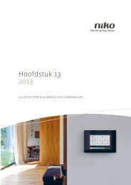
3. MONTAGE (fig. 2)<br />
Een <strong>Niko</strong>bus-drukknop kan op een enkelvoudige standaardinbouwdoos geschroefd worden, ongeacht enkelvoudige<br />
of meervoudige uitvoering van de muurprint. De busdrukknop wordt met een centrale schroef op de<br />
muurprint gemonteerd. Contactveren op de achterkant van de busdrukknoppen zorgen voor de elektrische<br />
verbinding tussen muurprint en drukknoppen. De muurprint wordt met de bus verbonden door een connector<br />
op de achterkant van de muurprint. Hierdoor zijn de busdrukknoppen afschroefbaar zonder dat het nodig is om<br />
de busbedrading los te maken.<br />
Installatievoorschriften<br />
- Meerdere ontvangers in dezelfde ruimte dienen buiten elkaars bereik te blijven.<br />
- Directe instraling van lichtbronnen zoals zon, verlichtingsarmaturen, HF TL-verlichting vermijden, want deze<br />
verminderen de gevoeligheid.<br />
- Er is geen combinatie mogelijk op de meervoudige muurprint met artikel 05-061.<br />
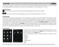
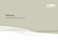
Aansluitschema IR-busdrukknoppen<br />
230V~<br />
230V~<br />
12V~<br />
C<br />
D<br />
L<br />
N<br />
aansluiting<br />
voor voeding<br />
muurprint (bv. 05-011-10)<br />
fig.1<br />
busaansluiting<br />
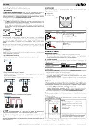
4. WERKING EN GEBRUIK<br />
LED licht continu op medium niveau in stand-by mode en doet dienst als nachtverlichting. Bij indrukken van<br />
één van de 4 lokale drukknoppen, licht de LED fel op zolang het bij deze toets horende <strong>Niko</strong>bus-telegram<br />
verstuurd wordt.<br />
Indien een toets langer dan ±8s ingedrukt wordt, stopt het zenden: de LED gaat naar stand-by mode.<br />
Als meerdere toetsen tegelijk ingedrukt worden, wordt het <strong>Niko</strong>bus-telegram van de laatst ingedrukte toets<br />
verzonden.<br />
Bij ontvangst van een correcte IR-signaalcode, knippert de LED:<br />
- traag knipperen bij ontvangst van een kanaalselectiecode: hierbij wordt geen <strong>Niko</strong>bus-telegram verstuurd, de<br />
LED knippert enkel ter indicatie van goede ontvangst.<br />
- snel knipperen bij ontvangst van een <strong>Niko</strong>bus-telegram: de LED knippert snel tijdens het versturen van het<br />
<strong>Niko</strong>bus-telegram dat hoort bij een ontvangen IR-signaalcode.<br />
Vooraleer er een <strong>Niko</strong>bus-telegram verstuurd wordt, wordt er gecheckt of de bus al dan niet bezet is. Indien<br />
ze bezet is, wordt er geen <strong>Niko</strong>bus-telegram verstuurd. De LED gaat naar stand-by mode. De ontvangen IRsignaalcode<br />
wordt niet bewaard en moet dus opnieuw gegeven worden als de bus weer vrij is. Bij ontvangst van<br />
een onbekende IR-signaalcode reageert de LED niet.<br />
5. TROUBLESHOOTING<br />
Probleem Oorzaak Oplossing<br />
- Algemene stroompanne?<br />
LED licht niet op. Geen voedingsspanning<br />
- Check hoofdzekering.<br />
- Check zekering van de beltrafo.<br />
LED reageert niet bij in- <strong>Niko</strong>bus is bezet. Wacht tot bus vrij is en druk opnieuw.<br />
drukken van de toets. Toets is reeds langer dan 8s ingedrukt. Laat toets los en druk opnieuw.<br />
<strong>Niko</strong>bus is bezet. Wacht tot bus vrij is en druk opnieuw.<br />
LED reageert niet op het<br />
- Druk eerst op <strong>Niko</strong>-toets (enkel voor uni-<br />
indrukken van een toets op<br />
de IR-afstandsbediening.<br />
Verkeerde IR-signaalcode<br />
versele afstandsbediening 05-089).<br />
- Gebruik enkel de kanaalselectie en/of<br />
commandotoetsen.<br />
De verzonden IR-signaalcode is een Gebruik de commandotoetsen voor<br />
LED reageert op het zen-<br />
kanaalselectiecode.<br />
acties.<br />
den van IR-code, maar er<br />
gebeurt niets.<br />
IR-signaalcode is niet geprogrammeerd - Selecteer eerst het juiste kanaal.<br />
in de <strong>Niko</strong>bus-modules.<br />
- Gebruik de juiste commandotoets.<br />
6. TECHNISCHE GEGEVENS<br />
Reikwijdte: ...............................10m<br />
Openingshoek: .........................45°<br />
Omgevingstemperatuur: ...........0 tot 50°C<br />
Rustspanning: ..........................9V DC (ZLVS, zeer lage veiligheidsspanning)<br />
Max. bedieningstijd: .................8s<br />
Aansluiting op de <strong>Niko</strong>bus: .......tweedraadsverbinding (fig.1)<br />
De <strong>Niko</strong>bus-IR-ontvanger-drukknop heeft een externe voedingsspanning nodig.<br />
Voedingsspanning: ...................9 - 12V~<br />
Stroomopname bij 12V~: .........10mA (stand-by; LED licht op medium niveau).<br />
30mA (piek als LED voluit oplicht).<br />
Opmerking: trafo dient gekeurd te zijn voor zeer lage veiligheidsspanning (ZLVS)<br />
7. GARANTIEBEPALINGEN<br />
- Garantietermijn: twee jaar vanaf leveringsdatum. Als leveringsdatum geldt de factuurdatum van aankoop van<br />
het goed door de consument. Indien geen factuur voorhanden is, geldt de productiedatum.<br />
- De consument is verplicht <strong>Niko</strong> schriftelijk over het gebrek aan overeenstemming te informeren, uiterlijk binnen<br />
de twee maanden na vaststelling.<br />
- In geval van een gebrek aan overeenstemming van het goed heeft de consument recht op een kosteloze<br />
herstelling of vervanging, wat door <strong>Niko</strong> bepaald wordt.<br />
- <strong>Niko</strong> is niet verantwoordelijk voor een gebrek of schade als gevolg van een foutieve installatie, oneigenlijk of<br />
onachtzaam gebruik of verkeerde bediening of transformatie van het goed.<br />
- De dwingende bepalingen van de nationale wetgevingen betreffende de verkoop van consumptiegoederen en de<br />
bescherming van de consumenten van de landen waarin <strong>Niko</strong> rechtstreeks of via zuster/dochtervennootschappen,<br />
filialen, distributeurs, agenten of vaste vertegenwoordigers verkoopt, hebben voorrang op bovenstaande<br />
bepalingen.<br />
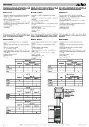
Voorbeeld van IR-busdrukknoppen met 05-091<br />
Adres op eerste IR-busdrukknop Andere IR-busdrukknoppen met een identiek adres (05-091)<br />
programmeren (bv. 05-091) nemen automatisch de acties van de reeds geprogrammeerde<br />
IR-busdrukknop over.<br />
fig.2<br />
A<br />
TOP<br />
B<br />
05-091 05-091 05-091<br />
inbouwdoos voor enkelvoudige<br />
schroefbevestiging muurprint afdekplaat busdrukknop toets<br />
nv <strong>Niko</strong> sa Industriepark West 40, BE-9100 Sint-Niklaas, Belgium — tel. +32 3 760 14 70 — fax +32 3 777 71 20 — e-mail: support@<strong>Niko</strong>.be — www.niko.be PM005-09100R07111<br />
C<br />
D<br />
A<br />
TOP<br />
B<br />
C<br />
D<br />
A<br />
TOP<br />
B<br />
C<br />
D
05-091/05-092/05-093/05-094/05-095<br />
Le bouton-poussoir IR avec une adresse identique: 05-091 / 05-092 / 05-093 / 05-094 / 05-095<br />
(seulement à 4 boutons de commande).<br />
Ce produit fait partie intégrante du système domotique <strong>Niko</strong>bus. Pour la description du sytème complet, veuillez<br />
consulter le catalogue <strong>Niko</strong>bus et le manuel d’installation.<br />
1. PRESCRIPTIONS LEGALES<br />
- Lisez entièrement le mode d’emploi avant toute installation et mise en service.<br />
- L’installation doit être effectuée par un installateur agréé et dans le respect des prescriptions en vigueur.<br />
- Ce mode d’emploi doit être remis à l’utilisateur. Il doit être joint au dossier de l’installation électrique et être<br />
remis à d’éventuels autres propriétaires. Des exemplaires supplémentaires peuvent être obtenus sur le site<br />
web ou auprès du service ‘support <strong>Niko</strong>’.<br />
- Il y a lieu de tenir compte des points suivants avant l’installation (liste non limitative):<br />
- les lois, normes et réglementations en vigueur;<br />
- l’état de la <strong>technique</strong> au moment de l’installation;<br />
- ce mode d’emploi qui doit être lu dans le cadre de toute installation spécifique;<br />
- les règles de l’art.<br />
- En cas de doute, vous pouvez appeler le service ‘support <strong>Niko</strong>’ ou vous adresser à un organisme de contrôle<br />
reconnu.<br />
Support Belgique: Support France:<br />
+ 32 3 760 14 82 + 33 4 78 66 66 20<br />
site web: http://www.niko.be site web: http://www.niko.fr<br />
e-mail: support@niko.be e-mail: ventes@niko.fr<br />
En cas de défaut de votre appareil, vous pouvez le retourner à un grossiste <strong>Niko</strong> agréé, accompagné d’une<br />
description détaillée de votre plainte (manière d’utilisation, divergence constatée…).<br />
2. DESCRIPTION<br />
Normalement chaque bouton-poussoir (B.P.) ainsi que chaque bouton-poussoir IR a une adresse unique. Cela<br />
signifie que chaque bouton-poussoir et chaque bouton-poussoir IR peuvent appeler une action différente. Si<br />
vous souhaitez que le bouton-poussoir IR appelle les mêmes actions depuis différents endroits sans pour autant<br />
devoir le reprogrammer à chaque fois, vous pouvez utiliser des boutons-poussoirs avec la même adresse. De<br />
cette manière seul un bouton-poussoir IR ne doit être programmé; les autres boutons-poussoirs IR, avec la<br />
même adresse, reprennent automatiquement les actions programmées. Vous déterminez le nombre souhaité de<br />
boutons-poussoirs IR avec adresse identique et vous les commandez sous une même référence (p. ex. 05-091).<br />
Souhaitez-vous programmer dans un même projet plusieurs actions et utiliser pour cela des boutons-poussoirs<br />
IR avec adresse identique, vous pouvez les grouper en 5 groupes max. ayant chacun leur propre référence:<br />
05-091, 05-092, 05-093, 05-094 et 05-095.<br />
Le bouton-poussoir (B.P.) possède 3 positions: haute, basse et médiane, avec récepteur infrarouge intégré. Ce<br />
récepteur IR est commandé par la télécommande infrarouge (05-088), la commande à distance universelle IR<br />
(05-089) ou le Pronto (05-090). Ces B.P. présentent le même aspect que les interrupteurs <strong>Niko</strong>bus, mais dans<br />
le système <strong>Niko</strong>bus ils n’ont pas la fonction d’interrupteur, mais d’émetteur d’information. Un B.P. <strong>Niko</strong>bus se<br />
visse sur un boîtier d'encastrement simple.<br />
Le raccordement de plusieurs B.P. sous une plaque de recouvrement multiple ne nécessite donc l’utilisation que<br />
d’un seul boîtier. Une extension des B.P. <strong>Niko</strong>bus s’effectue sans rainurage ou forage supplémentaire.<br />
Le B.P. <strong>Niko</strong>bus ne nécessite ni réglage ni adaptation. Les fonctions des B.P. ne sont pas déterminées par le B.P.<br />
lui-même, mais par la programmation que l’installateur effectue sur le module. Ces fonctions sont déterminées<br />
pendant la programmation du système, par simple pression sur les B.P.<br />
Une pression envoie un train d’impulsions (télégramme) sur le bus vers le module. Ce télégramme contient<br />
l’adresse du B.P. utilisé ainsi que l’information nécessaire à l‘exécution de l’ordre envoyé. Ce télégramme est<br />
véhiculé sur le bus par modulation de courant. Si le B.P. est maintenu en position enfoncée pendant plus de 8s,<br />
l’envoi du télégramme est interrompu et le câble-bus est libéré pour de nouvelles informations.<br />
A<br />
TOP<br />
B<br />
C<br />
D<br />
B.P. IR à 4 contacts avec adresse unique: 05-091 à 05-095<br />
3. MONTAGE (fig. 2)<br />
Un B.P. <strong>Niko</strong>bus peut être vissé sur une boîte d’encastrement standard simple, indépendamment de l’utilisation<br />
d’une platine murale simple ou multiple. Le B.P. est vissé au moyen d’une vis centrale sur la platine murale. Des<br />
ressorts de contact, situés sur la face arrière des B.P., assurent le contact électrique entre la platine murale et<br />
le B.P. La platine murale est reliée au câble-bus par un connecteur situé sur la face arrière de la platine murale.<br />
Ceci permet de dévisser des B.P. sans devoir déconnecter le raccordement du bus.<br />
Prescriptions d’installation<br />
- L’utilisation de plusieurs B.P. IR dans une même pièce doit s’effectuer de façon à ce que le faisceau IR n’atteigne<br />
qu’un B.P. à la fois.<br />
- Evitez que les B.P. ne soient soumis à une lumière directe du soleil, de lampes d’éclairage et HF TL, ce qui<br />
diminuerait la sensibilité des B.P.<br />
- Il n’est pas possible d’utiliser plusieurs B.P. IR sur une platine murale multiple 05-061.<br />
Raccordement des boutons-poussoirs IR<br />
230V~<br />
230V~<br />
12V~<br />
L<br />
N<br />
Raccordement<br />
de l'alimentation<br />
Platine murale (p.ex. 05-011-10)<br />
fig.1<br />
Raccordement du câble-bus<br />
4. FONCTIONNEMENT ET UTILISATION<br />
La LED reste allumée faiblement en position de médiane (stand-by) et fait office de point de repère dans le<br />
noir. En enfonçant une des 4 touches du B.P., la LED s’éclaire pleinement aussi longtemps que dure l’envoi<br />
du télégramme sur le bus. Si une touche est enfoncée plus de 8s, l’envoi du télégramme est interrompu et la<br />
LED reprend sa position de repos. Si l’on enfonce plusieurs touches simultanément, c’est le télégramme de la<br />
dernière touche enfoncée qui est envoyé.<br />
Lors de l’envoi d’un code IR correct, la LED clignote:<br />
- un clignotement lent pour l’envoi du code sélectif de canal; pas d’envoi de télégramme sur le bus, seulement<br />
une confirmation du choix du canal.<br />
- un clignotement rapide pour l’envoi d’un code de commande; en d’autres mots la LED clignote rapidement<br />
pendant l’envoi du télégramme de bus correspondant à l’envoi d’un signal code IR.<br />
Avant d’envoyer le télégramme sur le bus, le B.P. vérifie si le bus est libre. Si ce n’est pas le cas, aucun télégramme<br />
ne sera envoyé sur le bus et la LED se replace en position de repos. Le signal IR n’est pas mémorisé et il y a lieu<br />
de le réenvoyer dès que le bus est libéré. La LED ne réagit pas lors de l’envoi d’un signal code IR erroné.<br />
5. DERANGEMENTS<br />
Problème Cause Solution<br />
- Panne générale de courant?<br />
LED ne s’éclaire pas. Pas d’alimentation<br />
- Contrôlez le disjoncteur principal.<br />
- Contrôlez le fusible du transfo de sonnerie.<br />
LED ne réagit pas en <strong>Niko</strong>bus est occupé. Attendez que le bus se libère.<br />
enfonçant une touche<br />
du B.P.<br />
La touche est enfoncée depuis<br />
plus de 8s.<br />
Lachez la touche et réactivez.<br />
<strong>Niko</strong>bus est occupé. Attendez que le bus se libère.<br />
LED ne réagit pas en<br />
enfonçant une touche<br />
de la télécommande<br />
IR.<br />
LED réagit à l’envoi<br />
du code IR, mais rien<br />
ne se passe.<br />
Code IR erroné.<br />
Le code IR est un code de<br />
canal.<br />
Le code IR n'est pas<br />
programmé dans les modules<br />
<strong>Niko</strong>bus.<br />
- Enfoncez d'abord la touche <strong>Niko</strong> (seulement<br />
pour la commande universelle 05-089).<br />
- Utilisez uniquement la touche canal et/ou code<br />
IR.<br />
Utilisez la touche de ode IR.<br />
6. CARATERISTIQUES TECHNIQUES<br />
Portée: ....................................10m<br />
Angle de détection: ..................45°<br />
Température ambiante: ............0 à 50°C<br />
Tension de repos: .....................9V DC (TBTS)<br />
Temps de réponse max.: ..........8s<br />
Raccordement sur le <strong>Niko</strong>bus: ..2 fils (fig.1)<br />
Le B.P. IR <strong>Niko</strong>bus doit être alimenté séparémment.<br />
Alimentation: ...........................9 - 12V~<br />
Courant nominal sous 12V~: ....10mA (au repos, LED allumée faiblement).<br />
30mA (en pointe, LED allumée pleinement).<br />
Attention: le transfo doit être agréé pour tension TBTS.<br />
- Choisissez d'abord le canal adéquat.<br />
- Utlisez la touche de code IR correcte.<br />
7. CONDITIONS DE GARANTIE<br />
- Délai de garantie: 2 ans à partir de la date de livraison. La date de la facture d’achat par le consommateur fait<br />
office de date de livraison. Sans facture disponible, la date de fabrication est seule valable.<br />
- Le consommateur est tenu de prévenir <strong>Niko</strong> par écrit de tout manquement à la concordance des produits dans<br />
un délai max. de 2 mois après constatation.<br />
- Au cas ou pareil manquement serait constaté, le consommateur a droit à une réparation gratuite ou à un<br />
remplacement gratuit selon l’avis de <strong>Niko</strong>.<br />
- <strong>Niko</strong> ne peut être tenu pour responsable pour un défaut ou des dégâts suite à une installation fautive, à une<br />
utilisation contraire ou inadaptée ou à une transformation du produit.<br />
- Les dispositions contraignantes des législations nationales ayant trait à la vente de biens de consommation et la<br />
protection des consommateurs des différents pays où <strong>Niko</strong> procède à la vente directe ou par entreprises interposées,<br />
filiales, distributeurs, agents ou représentants fixes, prévalent sur les dispositions susmentionnées.<br />
Exemples de boutons-poussoirs IR qui ont l’adresse 05-091<br />
Programmez l'adresse au premier Les autres boutons-poussoirs IR, avec la même<br />
bouton-poussoir IR (p.ex. 05-091) adresse (05-091) reprennent automatiquement les<br />
actions du bouton-poussoir programmé.<br />
fig.2<br />
A<br />
TOP<br />
B<br />
05-091 05-091 05-091<br />
boîte<br />
d'encastrement pour platine murale plaque de<br />
raccordement par vis simple recouvrement bouton-poussoir manette<br />
nv <strong>Niko</strong> sa Industriepark West 40, BE-9100 Sint-Niklaas, Belgium — tel. +32 3 760 14 70 — fax +32 3 777 71 20 — e-mail: support@<strong>Niko</strong>.be — www.niko.be PM005-09100R07111<br />
C<br />
D<br />
A<br />
TOP<br />
B<br />
C<br />
D<br />
A<br />
TOP<br />
B<br />
C<br />
D
05-091/05-092/05-093/05-094/05-095<br />
Der IR-Bustaster mit identischen Adressen: 05-091 / 05-092 / 05-093 / 05-094 / 05-095 (nur mit 4<br />
Tastpunkten)<br />
Dieses Produkt ist ein Teil der <strong>Niko</strong>bus-Gebäudesystemtechnik. Zur technischen Beschreibung des gesamten<br />
Systems verweisen wir auf den <strong>Niko</strong>bus-Katalog sowie die <strong>Niko</strong>bus-Schulungsunterlage.<br />
1. GESETZLICHE BESTIMMUNGEN<br />
- Lesen Sie vor der Montage und Inbetriebnahme die vollständige Gebrauchsanleitung.<br />
- Die Installation darf ausschließlich von einem Fachmann des Elektrohandwerks unter Berücksichtigung der<br />
geltenden Vorschriften vorgenommen werden.<br />
- Übergeben Sie dem Benutzer diese Gebrauchsanleitung. Sie ist den Unterlagen der elektrischen Anlage beizufügen<br />
und muss auch eventuellen neuen Besitzern übergeben werden. Zusätzliche Exemplare erhalten Sie<br />
über unsere Website oder unseren Servicedienst.<br />
- Bei der Installation müssen Sie u.a. Folgendes berücksichtigen:<br />
- die geltenden Gesetze, Normen und Vorschriften;<br />
- den Stand der Technik zum Zeitpunkt der Installation;<br />
- diese Gebrauchsanleitung die im Zusammenhang mit jeder spezifischen Anlage gesehen werden muss;<br />
- die Regeln fachmännischen Könnens.<br />
- Sollten Sie Fragen haben, können Sie sich an die <strong>Niko</strong>-Hotline oder an eine anerkannte Kontrollstelle wenden:<br />
Web-site: http://www.niko.be; E-Mail: support@niko.be;<br />
Hotline Belgien: +32 3 760 14 82<br />
Hotline Moeller Deutschland:<br />
Berlin: +49 30 701902-46 Hamburg: +49 40 75019-281<br />
Düsseldorf: +49 2131 317-37 Frankfurt a.M.: +49 69 50089-263<br />
Stuttgart: +49 711 68789-51 München: +49 89 460 95-218<br />
Mail: gebaeudeautomation@moeller.net<br />
Österreich: Moeller Gebäudeautomation UG Schrems 0043-2853-702-0<br />
Hotline Slowakei: +421 263 825 155 – E-mail: niko@niko.sk<br />
Im Falle eines Defektes an Ihrem <strong>Niko</strong>-Produkt, können Sie dieses mit einer genauen Fehlerbeschreibung<br />
(Anwendungsproblem, festgestellter Fehler, usw.) an Ihren Moeller- oder <strong>Niko</strong>-EGH zurückbringen.<br />
2. BESCHREIBUNG<br />
Normalerweise besitzt jeder Bustaster und jeder IR-Bustaster eine eigene vorprogrammierte Adresse. Das heißt,<br />
dass jeder Bustaster und jeder IR-Bustaster eine andere Funktion enthalten kann. Möchten Sie, dass verschiedene<br />
IR-Bustaster die gleiche Funktion ausführen, ohne jeweils neu programmiert zu werden, können Sie IR-Bustaster<br />
mit identischer Adresse einsetzen. Auf diese Weise braucht nur ein IR-Bustaster programmiert zu werden. Die<br />
IR-Bustaster mit den identischen Adressen übernehmen diese Funktionen dann automatisch. Sie bestimmen die<br />
gewünschte Anzahl IR-Bustaster mit identischer Adressierung und bestellen diese unter einer Referenznummer (z.B.<br />
05-091). Möchten Sie in einem Projekt mehrere Funktionen programmieren unter Verwendung von IR-Bustaster<br />
mit identischer Adresse, so können Sie diese in Gruppen zusammenfassen, wobei maximal 5 Gruppen mit jeweils<br />
einer eigenen Bestellnummer zugeordnet sind: 05-091, 05-092, 05-093, 05-094 und 05-095.<br />
Der Bustaster ist ein Dreistellungstaster. Oben und unten sind die aktiven Stellungen, nicht betätigt ist die Wippe<br />
in neutraler Mittelstellung. Dieser Taster enthält einen integrierten IR-Empfänger.<br />
Der Infrarotempfänger kann mit dem IR-Handsender bedient werden (05-088), der universellen IR-Fernbedienung<br />
(05-089) oder dem IR-Pronto (05-090).<br />
Das Design der <strong>Niko</strong>bus-Taster entspricht dem der konventionellen <strong>Niko</strong>-Schalter. Im <strong>Niko</strong>bus-System dienen sie<br />
jedoch nicht als Schalter, sondern als Informationssender. Ein <strong>Niko</strong>bus-Taster wird mit der Montageleiterplatte auf<br />
eine Standard UP-Dose mit Schraubbefestigung montiert. Bei Mehrfachkombinationen sind keine zusätzlichen<br />
UP-Dosen erforderlich. Dadurch sind die <strong>Niko</strong>bus-Taster ohne zusätzliche Stemmarbeiten erweiterbar. Ein <strong>Niko</strong>bus-<br />
Taster benötigt keine Einstellungen. Die Funktionen des Bustasters wird nicht im Taster selbst festgelegt, sondern<br />
während der Programmierung auf/in dem Schalt-, Rolladenmodul oder Dimcontroller. Während der Einstellung<br />
des Systems werden die Funktionen der Bustaster durch einfaches Drücken von Tasten festgelegt. Beim Drücken<br />
der Wippe wird über den Bus ein Telegramm an das Modul gesendet, dass diese Adresse des Bustasters und<br />
eine Schaltinformation beinhaltet. Wird der Bustaster länger als 8s gedrückt, so wird das Telegramm automatisch<br />
unterbrochen und ist der Bus wieder frei. Die Telegrammübertragung geschieht durch Strommodulation.<br />
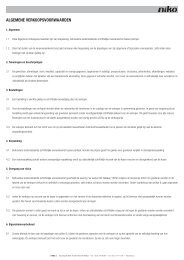
A<br />
TOP<br />
B<br />
C<br />
D<br />
IR-Bustaster mit identischen Adressen (4 Tastpunkten) 05-091 bis 05-095<br />
3. MONTAGE (Abb. 2)<br />
Ein <strong>Niko</strong>bus-Taster wird mit der Montageleiterplatte auf eine Standard-UP-Dose mit Schraubbefestigung montiert.<br />
Bei Mehrfachkombinationen sind keine zusätzlichen UP-Dosen erforderlich. Der <strong>Niko</strong>bus-Taster wird, unabhängig<br />
davon ob es sich um eine einfach- oder mehrfach- Leiterplatte handelt, mit einer zentralen Schraube auf den Bolzen<br />
der Leiterplatte geschraubt. Die auf der Rückseite des Bustasters angebrachten Kontaktfedern stellen die elektrische<br />
Verbindung zwischen Leiterplatte und Bustaster her. Die Anschlussklemmen auf der Rückseite der Leiterplatte werden<br />
mit der Busleitung verbunden. Damit ist es möglich, den Bustaster zu entfernen ohne die Busleitung zu lösen.<br />
Installationsvorschriften<br />
- Mehrere Empfänger im gleichen Raum dürfen ihren Empfangsbereich nicht überschneiden.<br />
- Direkten Lichteinfall wie z.B. Sonne, EVG- Leuchtmittel vermeiden, da diese die Empfindlichkeit verringern.<br />
- Auf einer Montageleiterplatte ist keine Kombination mit dem Bustaster mit LED 05-061 möglich.<br />
Anschlussschema IR-Bustaster<br />
230V~<br />
230V~<br />
12V~<br />
L<br />
N<br />
Anschluss für<br />
Stromversorgung<br />
Abb.1<br />
Busanschluss<br />
4. ARBEITSWEISE UND EINSATZ<br />
LED leuchtet im Stand-by Modus schwach und dient als Orientierungslicht. Beim Betätigen einer der Wippen<br />
leuchtet die LED so lange hell, wie das zu dieser Taste gehörende <strong>Niko</strong>bus-Telegramm gesendet wird.<br />
Wenn eine Taste länger als ± 8s gedrückt wird, so wird die Übertragung unterbrochen. Die LED geht in den<br />
Stand-by Modus zurück. Bei gleichzeitigem Drücken mehrerer Tasten wird das <strong>Niko</strong>bus-Telegramm der zuletzt<br />
gedrückten Taste gesendet.<br />
Beim Empfang eines korrekten IR-Signalcodes blinkt die LED wie folgt:<br />
- langsames Blinken beim Empfang eines Kanalwahlcodes: hierbei wird kein <strong>Niko</strong>bus-Telegramm gesendet, die<br />
LED blinkt nur zur Anzeige des einwandfreien Empfangs.<br />
- schnelles Blinken beim Empfang eines Bustelegramms: die LED blinkt während des Versendens des <strong>Niko</strong>bus-<br />
Telegramms schnell.<br />
Bevor ein <strong>Niko</strong>bus-Telegramm gesendet wird, wird untersucht ob der Bus frei ist. Ist der Bus besetzt, so wird<br />
kein <strong>Niko</strong>bus-Telegramm gesendet. Die LED geht dann in den stand-by-Modus. Das IR-Signal wird nicht im<br />
Empfänger gespeichert und muss deshalb erneut gesendet werden wenn der Bus wieder frei ist. Beim Empfang<br />
eines fremden IR-Signals reagiert die LED nicht.<br />
5. FEHLERBEHEBUNG<br />
Problem Ursache Ursache<br />
- Allgemeiner Stromausfall?<br />
LED leuchtet nicht auf. keine Versorgungsspannung - Hauptsicherung prüfen.<br />
- Sicherung des Klingeltrafos prüfen.<br />
LED reagiert nicht bei<br />
Drücken einer Taste.<br />
<strong>Niko</strong>bus ist besetzt.<br />
Taste ist bereits länger als 8s<br />
gedrückt.<br />
Warten, bis der Bus frei ist und erneut drücken.<br />
Warten, bis der Bus frei ist und erneut drücken.<br />
<strong>Niko</strong>bus ist besetzt. Warten, bis der Bus frei ist und erneut drücken.<br />
LED reagiert nicht auf<br />
IR-Fernbedienung. Falscher IR-Signalcode<br />
- Drücken Sie erst auf die <strong>Niko</strong>-Taste (nur für<br />
Fernbedienung 05-089).<br />
- Benutzen Sie nur die Kanalwahl und/oder die<br />
Befehlstasten.<br />
LED reagiert auf das<br />
Senden IR-Codes,<br />
jedoch keine Reaktion.<br />
Der versandte IR Signalcode ist<br />
ein Kanalwahlcode.<br />
IR- Signalcode ist nicht in den<br />
<strong>Niko</strong>bus-Modulen programmiert.<br />
Benutzen Sie die Befehlstasten.<br />
- Wählen Sie erst den richtigen Kanal.<br />
- Benutzen Sie die richtige Befehlstaste.<br />
6. TECHNISCHE DATEN<br />
Reichweite: ..............................10m<br />
Öffnungswinkel: .......................45°<br />
Umgebungstemperatur: ............0 bis 50°C<br />
Betriebsbusspannung: ..............9V DC (Sicherheitskleinspannung)<br />
Max. Bedienungszeit: ...............8s<br />
Anschluss an den <strong>Niko</strong>bus: .......Zwei-Draht-Leitung (Abb.1)<br />
Der <strong>Niko</strong>bus IR-Bustaster bedarf einer externen Strommversorgung.<br />
Externe Stromversorgung: ........9 - 12V~<br />
Stromaufnahme bei 12V~: .......10mA (stand-by; wenn die LED schwach leuchtet).<br />
30mA (Wenn die LED voll leuchtet).<br />
Bemerkung: Als Transformator darf nur ein Sicherheitstrafo nach VDE-Richtlinien eingesetzt werden.<br />
7. GARANTIEBESTIMMUNGEN<br />
- Garantiezeitraum: Zwei Jahre ab Lieferdatum. Als Lieferdatum gilt das Rechnungsdatum zu dem der Endkunde<br />
das Produkt gekauft hat. Falls keine Rechnung mehr vorhanden ist, gilt das Produktionsdatum.<br />
- Der Endkunde ist verpflichtet, <strong>Niko</strong> über den festgestellten Mangel innerhalb von zwei Monaten zu informieren.<br />
- Im Falle eines Mangels an dem Produkt hat der Endkunde das Recht auf eine kostenlose Reparatur oder Ersatz.<br />
Dies wird von <strong>Niko</strong> entschieden.<br />
- <strong>Niko</strong> ist nicht für einen Mangel oder Schaden verantwortlich, der durch unsachgemäße Installation, nicht bestimmungsgemäßen<br />
oder unvorsichtigen Gebrauch oder falsche Bedienung oder Anpassen/Ändern des Produktes entsteht.<br />
- Die zwingenden Vorschriften der nationalen Gesetzgebung bezüglich des Verkaufs von Konsumgütern und<br />
der Schutz des Kunden in den Ländern in denen <strong>Niko</strong> direkt oder über seine Tochtergesellschaften, Filialen,<br />
Distributoren, Handelsvertretungen oder Vertretern verkauft, haben Vorrang vor den obigen Bestimmungen.<br />
Beispiel IR-Bustaster mit 05-091<br />
Adresse in IR-Bustaster Die anderen IR-Bustaster mit identischen Adressen<br />
programmieren (z.B. 05-091) (05-091) übernehmen dann automatisch die Funktionen<br />
des bereits programmierten ersten Bustasters.<br />
Abb.2<br />
A<br />
TOP<br />
B<br />
05-091 05-091 05-091<br />
Einbaudose mit Leiterplatte<br />
Leiterplatte (z.B.: 05-011-10)<br />
Schraubbefestigung einfach Abdeckplatte Bustaster Taste<br />
nv <strong>Niko</strong> sa Industriepark West 40, BE-9100 Sint-Niklaas, Belgium — tel. +32 3 760 14 70 — fax +32 3 777 71 20 — e-mail: support@<strong>Niko</strong>.be — www.niko.be PM005-09100R07111<br />
C<br />
D<br />
A<br />
TOP<br />
B<br />
C<br />
D<br />
A<br />
TOP<br />
B<br />
C<br />
D
05-091/05-092/05-093/05-094/05-095<br />
IR bus push button with identical addresses: 05-091/05-092/05-093/05-094/05-095 (only with 4<br />
control points)<br />
This product is part of the <strong>Niko</strong>bus home automation system. For a description of the complete system, please<br />
consult the <strong>Niko</strong>bus catalogue and the installation manual or visit our website www.niko.be.<br />
1. LEGAL WARNINGS<br />
- Read the complete manual before attempting installation and activating the system.<br />
- The installation has to be carried out by a registered installer and in compliance with the statutory regulations.<br />
- This user manual has to be handed over to the user. It has to be included in the electrical installation file and<br />
has to be passed on to any new owners. Additional copies are available on the <strong>Niko</strong> website or via the support<br />
service.<br />
- During installation, the following has to be taken into account (not limited to list below):<br />
- The statutory laws, standards and regulations;<br />
- The state of the art <strong>technique</strong> at the moment of installation;<br />
- This user manual, which must be read within the scope of each specific installation, only states general<br />
regulations;<br />
- The rules of proper workmanship<br />
- In case of questions, you can consult <strong>Niko</strong>’s support service or contact a registered control organisation.<br />
Support Belgium: Support Slovakia:<br />
+32 3 760 14 82 +421 263 825 155<br />
website : http://www.niko.be e-mail: niko@niko.sk<br />
e-mail: support@niko.be<br />
In case of a defect, you can return your product to a registered <strong>Niko</strong> wholesaler, together with a clear description<br />
of your complaint (Conditions of use, stated defect…).<br />
2. DESCRIPTION<br />
Normally, each bus push button and IR bus push button has a unique number, which means that each bus push<br />
button and IR bus push button can call different actions. However, if you want the IR bus push button to call the<br />
same actions from different places without programming each time, you can use the IR bus push buttons with<br />
identical address. This way, only one IR bus push button needs to be programmed. The IR bus push buttons with<br />
identical address will automatically take over these actions. Determine the number of IR bus push buttons with<br />
identical address and order them under one reference (e.g. 05-091). If you want to program several actions in<br />
one project and want to use IR bus push buttons with identical address, you can group them in max. 5 groups<br />
with the following order numbers: 05-091,05-092, 05-093, 05-094 and 05-095.<br />
The bus push button is a three-position push button: it consists of an upper, a lower and a neutral (central)<br />
position, with an integrated infrared receiver. This infrared receiver functions in combination with infrared remote<br />
control (05-088), the IR universal remote control (05-089) or the IR Pronto (05-090). The bus push buttons have<br />
the familiar appearance of the <strong>Niko</strong>bus switches, but in the <strong>Niko</strong>bus system they are used not as switches but as<br />
data transmitters. A <strong>Niko</strong>bus push button is mounted in a single standard flush mounting box for screw fixing. For<br />
mounting under multiple cover plates, no additional flush mounting boxes are required. The number of <strong>Niko</strong>bus<br />
push buttons can be extended without drilling or channelling work. The <strong>Niko</strong>bus push button does not require any<br />
setting or adjustment whatsoever. The functions of the bus push buttons are determined not by the push button<br />
itself, but by the module settings performed by the installer. During the system setting, the functions of the bus<br />
push buttons are defined simply by operating the buttons. When activating a button, a telegram is sent via the<br />
bus to the module. This telegram contains the address of the bus push button and the information on the action<br />
to be carried out. This telegram transmission is accomplished by means of current modulation.<br />
If the bus push button is pressed for more than 8s, the telegram is automatically interrupted and the bus is<br />
free again.<br />
A<br />
TOP<br />
B<br />
C<br />
D<br />
IR bus push button with 4 keys: 05-091 — 05-095<br />
3. MOUNTING (fig. 2)<br />
A <strong>Niko</strong>bus push button can be screwed onto a single standard flush mounting box, irrespective of whether a<br />
single or multiple wall-mounted PCB is used. The bus push button is mounted on the wall-mounted PCB with a<br />
central screw. Contact springs on the back of the bus push buttons ensure the electrical connection between the<br />
wall-mounted PCB and the push buttons. The PCB is connected to the bus via a connector on the back of the PCB.<br />
This means that the bus push buttons can be screwed off without having to disconnect the bus wiring.<br />
Installation instructions<br />
- When using several receivers in the same room, they must be operated outside each other’s range.<br />
- The bus push buttons must not be exposed to direct radiation from light sources such as sunlight, incandescent<br />
lamps and HF TL lighting as this will reduce the sensitivity of the bus push buttons.<br />
- The combination of bus push buttons on the multiple wall-mounted printed circuit board (PCB) with reference<br />
05-061 is not possible.<br />
Wiring diagram for IR bus push buttons<br />
230V~<br />
230V~<br />
12V~<br />
L<br />
N<br />
power supply<br />
wall-mounted PCB (e.g. 05-011-10)<br />
fig.1<br />
bus connection<br />
4. OPERATION AND USE<br />
In stand-by mode, the LED is continuously half-lit and serves as night illumination. When pressing one of the 4<br />
local push buttons, the LED lights fully for as long as the corresponding <strong>Niko</strong> code is transmitted over the bus.<br />
If a button is pressed for more than ±8s, the transmission stops. The LED then returns to stand-by mode.<br />
When pressing several buttons simultaneously, the code of the last button pressed is transmitted.<br />
The LED blinks upon receipt of a correct IR code:<br />
- It blinks slowly upon receipt of a channel selection code: here, no <strong>Niko</strong> code is transmitted, the LED only blinks<br />
to indicate the correct receipt.<br />
- It blinks quickly upon receipt of a command code: the LED blinks quickly during transmission of the <strong>Niko</strong> code<br />
that corresponds to a received IR command code.<br />
Before a <strong>Niko</strong> code is transmitted, it checks whether the bus is free or not. If it is engaged, no <strong>Niko</strong> code is<br />
transmitted and the LED returns to stand-by mode. The received command is not saved and must therefore be<br />
repeated when the bus is free again.<br />
The LED does not respond when an unknown IR code is received.<br />
5. TROUBLESHOOTING<br />
Problem Cause Remedy<br />
- General power failure?<br />
LED does not lights. No supply voltage<br />
- Check main fuse.<br />
- Check fuse of bell transformer.<br />
LED does not respond <strong>Niko</strong>bus is busy. Wait until bus is free and press again.<br />
when pressing one of<br />
the keys.<br />
Button has been pressed for more<br />
than 8s.<br />
Let go of button and press again.<br />
LED does not respond <strong>Niko</strong>bus is busy. Wait until bus is free and press again.<br />
when pressing a key<br />
- First press <strong>Niko</strong> key (only for the universal<br />
on the IR remote Wrong IR code<br />
remote control /05-089).<br />
control.<br />
- Use only the channel and/or command keys.<br />
LED responds to the<br />
transmitted IR code,<br />
but nothing happens.<br />
Transmitted IR code is a channel<br />
selection code.<br />
IR code not programmed in the<br />
<strong>Niko</strong>bus modules.<br />
Use the action command keys.<br />
- First select the correct channel.<br />
- Use the correct command key.<br />
6. TECHNICAL DATA<br />
Range: ....................................10m<br />
Opening angle: ........................45°<br />
Operating temperature: ............0 to 50°C<br />
Open-circuit voltage: ................9V DC (VLSV, very low safety voltage)<br />
Max. control time: ....................8s<br />
Connection to the <strong>Niko</strong>bus: .......two-wire connection (fig.1)<br />
The <strong>Niko</strong>bus IR receiver push button requires an external power supply.<br />
Power supply: ..........................9 - 12V~<br />
Current consumption at 12V~: ..10mA (stand-by; LED half-lit).<br />
30mA (peak; LED fully lit).<br />
Note: The transformer has to be approved for very low safety voltage (VLSV)<br />
7. GUARANTEE PROVISIONS<br />
- Period of guarantee: 2 years from date of delivery. The delivery date is the invoice date of purchase of the<br />
product by the consumer. If there is no invoice, the date of production applies.<br />
- The consumer is obliged to inform <strong>Niko</strong> in writing about the defect, within two months after stating the defect.<br />
- In case of a failure to conform, the consumer has the right to a repair or replacement (decided by <strong>Niko</strong>) free of<br />
charge.<br />
- <strong>Niko</strong> cannot be held liable for a defect or damage as a result of an incorrect installation, improper or careless<br />
use or wrong usage or transformation of the goods.<br />
- The compulsory regulations of the national legislation concerning the sales of consumer goods and the protection<br />
of the consumers in the countries where <strong>Niko</strong> sells, directly or via sister or daughter companies, chain stores,<br />
distributors, agents or permanent sales representatives, take priority over the rules and regulations mentioned<br />
above.<br />
Example of IR bus push buttons with 05-091<br />
Program address on the first IR Other IR bus push buttons with identical address<br />
bus push button (e.g. 05-091) (05-091) automatically take over the actions<br />
of the programmed IR bus push button.<br />
fig.2<br />
A<br />
TOP<br />
B<br />
05-091 05-091 05-091<br />
flush mounting box single wallfor<br />
screwing mounted PCB cover plate bus push button rocker<br />
nv <strong>Niko</strong> sa Industriepark West 40, BE-9100 Sint-Niklaas, Belgium — tel. +32 3 760 14 70 — fax +32 3 777 71 20 — e-mail: support@<strong>Niko</strong>.be — www.niko.be PM005-09100R07111<br />
C<br />
D<br />
A<br />
TOP<br />
B<br />
C<br />
D<br />
A<br />
TOP<br />
B<br />
C<br />
D