Point Spread Function Protocol Olympus FV1000
Point Spread Function Protocol Olympus FV1000
Point Spread Function Protocol Olympus FV1000

You also want an ePaper? Increase the reach of your titles
YUMPU automatically turns print PDFs into web optimized ePapers that Google loves.
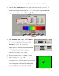
ABRF – Light Microscopy Research Group (LMRG) - <strong>Point</strong> <strong>Spread</strong> <strong>Function</strong> Measurements - <strong>Olympus</strong> <strong>FV1000</strong><br />
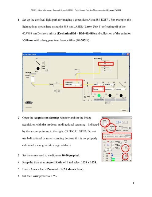
1 Set up the confocal light path for imaging a green dye (Alexa488-EGFP). For example, the<br />
light path as shown here using the 488 nm LASER (Laser Unit 1) reflecting off of the<br />
405/488 nm Dichroic mirror (ExcitationDM – DM405/488) and collection of the emission<br />
>510 nm with a long pass interference filter (BA505IF).<br />
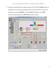
2 Open the Acquisition Settings window and set the image<br />
acquisition with the mode as unidirectional scanning - indicated<br />
by the arrows pointing to the right. CRITICAL STEP: Do not<br />
use bidirectional or raster scanning because if it is not properly<br />
calibrated it can generate image artifacts.<br />
3 Set the scan speed to medium or 10-20 μs/pixel.<br />
4 Keep the Size at an Aspect Ratio of 1 and select 1024 x 1024.<br />
5 Under Area select a Zoom of ~3 (2.7 shown here).<br />
6 Set the Laser power to 0.5%.<br />
1
ABRF – Light Microscopy Research Group (LMRG) - <strong>Point</strong> <strong>Spread</strong> <strong>Function</strong> Measurements - <strong>Olympus</strong> <strong>FV1000</strong><br />
7 Open the Image Acquisition<br />
Control window. Set up the Channel<br />
detection (CH1) so that it is at high<br />
detector sensitivity (HV ~700), low<br />
Gain (1) and low offset (~6%). Use<br />
the XY Repeat function and scan the<br />
bead sample. The image should<br />
default to a 12-Bit format. Set the confocal aperture (C.A.) or pinhole to 1 Airy Unit by<br />
clicking the Auto button. CRITICAL STEP: Under Filter Mode make sure the Kalman<br />
filtering is not selected as any image filtering can cause image artifacts. Use the Hi-Lo look<br />
up table (LUT) setting and make sure there are no blue pixels (measuring zero intensity), and<br />
no red pixels (measuring saturation). You can press Ctrl-H to select the Hi-Lo LUT. If there<br />
are blue pixels put down the offset, if there are red pixels reduce the LASER power. If you<br />
reach minimum LASER power you can reduce the HV voltage setting.<br />
8 Press the XY button on the<br />
Image Acquisition Control<br />
window to generate an image of<br />
the beads.<br />
2
ABRF – Light Microscopy Research Group (LMRG) - <strong>Point</strong> <strong>Spread</strong> <strong>Function</strong> Measurements - <strong>Olympus</strong> <strong>FV1000</strong><br />
9 Under the Acquisition Settings use the clip tool to select a single bead for imaging.<br />
10 Press the XY button on the Image Acquisition Control window and take an image of the<br />
single bead.<br />
11 Select the Image Information button on the Image<br />
Acquisition Control window. This will open up the<br />
Information window where the image pixel size and the clip<br />
region information will appear.<br />
3
ABRF – Light Microscopy Research Group (LMRG) - <strong>Point</strong> <strong>Spread</strong> <strong>Function</strong> Measurements - <strong>Olympus</strong> <strong>FV1000</strong><br />
12 Verify that the image pixel size is<br />
within the recommended settings in<br />
Table 1 of the main protocol (0.076<br />
µm or 76 nm for a 60X/1.4 NA oil<br />
immersion objective lens). If it is<br />
not adjust the zoom factor to obtain<br />
ideal sampling.<br />
13 Verify the image acquisition settings using the Hi-Lo LUT.<br />
14 See the main protocol paper for details on how to<br />
properly set the Z-image spacing. Under the<br />
Acquisition Setting window activate the<br />
Microscope window. Use the XY repeat or<br />
Focusx2 scanning mode and set the Z-Stack<br />
options. Manually focus or click on the yellow<br />
arrow buttons to focus below the beads. Click the<br />
Set button Start. Focus above the microsphere and<br />
click the Set button<br />
below End. Press the<br />
Stop button to stop<br />
scanning.<br />
4
ABRF – Light Microscopy Research Group (LMRG) - <strong>Point</strong> <strong>Spread</strong> <strong>Function</strong> Measurements - <strong>Olympus</strong> <strong>FV1000</strong><br />
15 Adjust the StepSize or the Slices to achieve ideal sampling in Z (see the main protocol).<br />
16 Perform the Z-Stack acquisition by selecting Depth and pressing on the XY button.<br />
17 Right click on the image to save the image stack as an OIF file and also a .tif file.<br />
18 Save all your files with your name and the name of the instrument you collected the data<br />
on. Send the following information to the ABRF-LMRG at abrf.lmrg@gmail.com:<br />
a) Summary of the measured resolution in X,Y,Z for at least 5 microspheres measured<br />
with the pinhole set to 1 Airy Unit.<br />
b) One representative MetroloJ report for data collected with the pinhole set to 1 Airy<br />
Unit.<br />
c) Summary of the measured resolution in X,Y,Z for at least 5 microspheres measured<br />
with the pinhole set to 5 Airy Units.<br />
d) One representative MetroloJ report for data collected with the pinhole set to 5 Airy<br />
Units.<br />
5