Analysis and design of slopes for Rajo Sur, an ... - SRK Consulting
Analysis and design of slopes for Rajo Sur, an ... - SRK Consulting
Analysis and design of slopes for Rajo Sur, an ... - SRK Consulting

You also want an ePaper? Increase the reach of your titles
YUMPU automatically turns print PDFs into web optimized ePapers that Google loves.
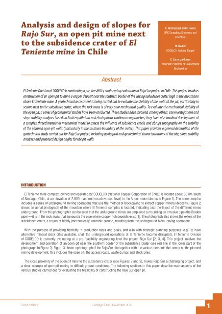
<strong>Analysis</strong> <strong><strong>an</strong>d</strong> <strong>design</strong> <strong>of</strong> <strong>slopes</strong> <strong>for</strong><br />
<strong>Rajo</strong> <strong>Sur</strong>, <strong>an</strong> open pit mine next<br />
to the subsidence crater <strong>of</strong> El<br />
Teniente mine in Chile<br />
INTRODUCTION<br />
Abstract<br />
El Teniente Division <strong>of</strong> CODELCO is conducting a pre-feasibility engineering evaluation <strong>of</strong> <strong>Rajo</strong> <strong>Sur</strong> project in Chile. This project involves<br />
construction <strong>of</strong> <strong>an</strong> open pit to mine a copper deposit near the southern border <strong>of</strong> the caving subsidence crater high in the mountains<br />
above El Teniente mine. A geotechnical assessment is being carried out to evaluate the stability <strong>of</strong> the walls <strong>of</strong> the pit, particularly in<br />
sectors next to the subsidence crater, where the rock mass is <strong>of</strong> very poor mech<strong>an</strong>ical quality. To evaluate the mech<strong>an</strong>ical stability <strong>of</strong><br />
the open pit, a series <strong>of</strong> geotechnical studies have been conducted. These studies have involved, among others, site investigations <strong><strong>an</strong>d</strong><br />
slope stability <strong>an</strong>alyses based on limit equilibrium <strong><strong>an</strong>d</strong> elastoplastic continuum approaches; they have also involved development <strong>of</strong><br />
a complex threedimensional mech<strong>an</strong>ical model to assess the influence <strong>of</strong> subsidence cracks <strong><strong>an</strong>d</strong> abrupt topography on the stability<br />
<strong>of</strong> the pl<strong>an</strong>ned open pit walls (particularly in the southern boundary <strong>of</strong> the crater). This paper provides a general description <strong>of</strong> the<br />
geotechnical study carried out <strong>for</strong> <strong>Rajo</strong> <strong>Sur</strong> project, including geological <strong><strong>an</strong>d</strong> geotechnical characterizations <strong>of</strong> the site, slope stability<br />
<strong>an</strong>alyses <strong><strong>an</strong>d</strong> proposed <strong>design</strong> <strong>an</strong>gles <strong>for</strong> the pit walls.<br />
El Teniente mine complex, owned <strong><strong>an</strong>d</strong> operated by CODELCO (National Copper Corporation <strong>of</strong> Chile), is located about 80 km south<br />
<strong>of</strong> S<strong>an</strong>tiago, Chile, at <strong>an</strong> elevation <strong>of</strong> 2,500 masl (meters above sea level) in the Andes mountains (see Figure 1). The mine complex<br />
includes a series <strong>of</strong> underground mining operations that use the method <strong>of</strong> blockcaving to extract copper mineral deposits. Figure 2<br />
shows <strong>an</strong> aerial photograph <strong>of</strong> the mountain where El Teniente complex is located, indicating also the layout <strong>of</strong> the different mines<br />
underground. From this photograph it c<strong>an</strong> be seen that the underground mines are emplaced surrounding <strong>an</strong> intrusive pipe (the Braden<br />
pipe) —it is in the rock mass that surrounds the pipe where copper rich deposits exist [1]. The photograph also shows the extent <strong>of</strong> the<br />
subsidence crater, a region <strong>of</strong> highly (mech<strong>an</strong>ically) unstable ground, resulting from the underground block-caving operations.<br />
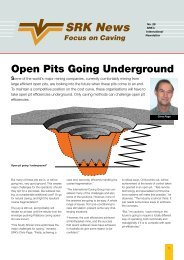
With the purpose <strong>of</strong> providing flexibility in production rates <strong><strong>an</strong>d</strong> goals, <strong><strong>an</strong>d</strong> also with strategic pl<strong>an</strong>ning purposes (e.g., to have<br />
alternative mineral stock piles available, shall the underground operations at El Teniente become disrupted), El Teniente Division<br />
<strong>of</strong> CODELCO is currently evaluating at a pre-feasibility engineering level the project <strong>Rajo</strong> <strong>Sur</strong> [2, 3, 4]. This project involves the<br />
development <strong><strong>an</strong>d</strong> operation <strong>of</strong> <strong>an</strong> open pit near the southern border <strong>of</strong> the subsidence crater (see red line in the lower part <strong>of</strong> the<br />
photograph in Figure 2). Figure 3 shows a photograph <strong>of</strong> the <strong>Rajo</strong> <strong>Sur</strong> site together with the various elements that comprise the pl<strong>an</strong>ned<br />
mining development; this includes the open pit, the access roads, waste dumps <strong><strong>an</strong>d</strong> stock piles.<br />
The close proximity <strong>of</strong> the open pit mine to the subsidence crater (see Figures 2 <strong><strong>an</strong>d</strong> 3), makes <strong>Rajo</strong> <strong>Sur</strong> a challenging project, <strong><strong>an</strong>d</strong><br />
a clear example <strong>of</strong> open pit mining in difficult ground conditions. The following sections in this paper describe main aspects <strong>of</strong> the<br />
various studies carried out <strong>for</strong> evaluating the feasibility <strong>of</strong> constructing the <strong>Rajo</strong> <strong>Sur</strong> open pit.<br />
Slope Stability S<strong>an</strong>tiago Chile, November 2009<br />
E. Hormazabal <strong><strong>an</strong>d</strong> F. Rovira<br />
<strong>SRK</strong> <strong>Consulting</strong>, Engineers <strong><strong>an</strong>d</strong><br />
Scientists<br />
M. Walker<br />
CODELCO, National Copper<br />
C. Carr<strong>an</strong>za-Torres<br />
Associate Pr<strong>of</strong>essor <strong>of</strong> Geotechnical<br />
Engineering
Figure 1 - El Teniente mine location, in relation to S<strong>an</strong>tiago <strong><strong>an</strong>d</strong> R<strong>an</strong>cagua cities in Chile.<br />
Figure 2 - Aerial photograph <strong>of</strong> subsidence crater at El Teniente —the photograph indicates the boundaries <strong>of</strong> the crater,<br />
underground mining works,<strong><strong>an</strong>d</strong> northern border <strong>of</strong> the pl<strong>an</strong>ned <strong>Rajo</strong> <strong>Sur</strong> open pit.<br />
S<strong>an</strong>tiago Chile, November 2009 Slope Stability
Figure 3 - Aerial photograph <strong>of</strong> <strong>Rajo</strong> <strong>Sur</strong> project site —dotted red lines indicate current subsidence crater boundary (see Figure 2);<br />
also indicated are waste dump alternatives (1A <strong><strong>an</strong>d</strong> 1B), stockpiles (2) <strong><strong>an</strong>d</strong> secondary road (3).<br />
GEOLOGICAL CHARACTERIZATION<br />
The main rock types at <strong>Rajo</strong> <strong>Sur</strong> site include micro-porphyric to porphyric rocks <strong>of</strong> <strong><strong>an</strong>d</strong>esite-basalt type, grey colored <strong><strong>an</strong>d</strong> <strong>of</strong> mafic composition,<br />
corresponding to CMET (‘Complejo Máfico El Teniente’) type; these CMET rocks present moderate to intense argillic <strong><strong>an</strong>d</strong>/or quarz-sericitic<br />
alteration, <strong><strong>an</strong>d</strong> light to moderate cloritization; other rocks at <strong>Rajo</strong> <strong>Sur</strong> site include Tonalite to Diorite <strong><strong>an</strong>d</strong> Tonalite to Diorite porphyry rocks, with<br />
moderate to intense argillic <strong><strong>an</strong>d</strong>/or quartz-sericitic alteration <strong>of</strong> difficult classification <strong><strong>an</strong>d</strong> characterization. In some sectors a ferrocrete stratum<br />
c<strong>an</strong> also be found overlying these rocks. Figure 4 shows a schematic representation <strong>of</strong> the lithology described above; the figure also indicates<br />
the boundaries <strong>of</strong> the pl<strong>an</strong>ned pit in the final excavation stage.<br />
According to the geotechnical in<strong>for</strong>mation gathered from mapping <strong><strong>an</strong>d</strong> logging <strong>of</strong> several campaigns in the years 2006, 2007 <strong><strong>an</strong>d</strong> 2008 in<br />
various sectors at <strong>Rajo</strong> <strong>Sur</strong> [5, 6], three structural domains c<strong>an</strong> be distinguished based on their predomin<strong>an</strong>t location: i) NW domain, located in the<br />
lower (altitude) zone <strong>of</strong> the pl<strong>an</strong>ned pit; ii) NE (central) domain, located in the medium (altitude) part <strong>of</strong> the pl<strong>an</strong>ned pit, <strong><strong>an</strong>d</strong> iii) SE domain, located<br />
in the higher (altitude) zone <strong>of</strong> the pl<strong>an</strong>ned open pit —the boundaries <strong>of</strong> the different domains, in relation to the boundaries <strong>of</strong> the pl<strong>an</strong>ned open<br />
pit (<strong>for</strong> the final excavation stage) are shown in a topographical map in Figure 5. In agreement with Figure 4, the main lithological units in the NW<br />
<strong><strong>an</strong>d</strong> SE domains correspond to CMET rock type, while in the NE (or central) domain, correspond to Tonalite <strong><strong>an</strong>d</strong> Diorite rock types.<br />
<strong>Sur</strong>face mapping <strong><strong>an</strong>d</strong> core log <strong>an</strong>alyses carried out by <strong>SRK</strong> <strong><strong>an</strong>d</strong> El Teniente division geologists <strong><strong>an</strong>d</strong> engineers, has led to conclude there<br />
are not first order (or mayor) faults in the area [5, 6]. The studies have also revealed that there are structural features <strong>of</strong> 2nd <strong><strong>an</strong>d</strong> 3rd order<br />
mainly (i.e., minor faults <strong><strong>an</strong>d</strong> joints). The occurrence <strong>of</strong> these structural features are summarized in the stereonets in Figure 5 —these<br />
represent distribution <strong>of</strong> poles <strong>of</strong> minor faults <strong><strong>an</strong>d</strong> joints, respectively, in a lower hemisphere projection.<br />
As part <strong>of</strong> the geological characterization, a hydrogeological conceptual model has also been developed based on piezometers, borehole<br />
loggings <strong><strong>an</strong>d</strong> outcrop in<strong>for</strong>mation at the site. Three main hydrogeological units have been identified, namely: i) <strong>an</strong> alluvial layer with<br />
a thickness <strong>of</strong> 5 to 10 m; ii) a permeable unit related to a secondary geotechnical unit with a thickness <strong>of</strong> 60 to 170 m; <strong><strong>an</strong>d</strong> iii) <strong>an</strong><br />
impermeable unit. The <strong>an</strong>nual fluctuation <strong>of</strong> (underground)water levels has shown a difference <strong>of</strong> 30mbetween winter (snow-icing) <strong><strong>an</strong>d</strong><br />
spring (snow melting) seasons. In the developed hydrogeological model, the equipotential curves show a higher hydraulic gradient towards<br />
the subsidence crater <strong><strong>an</strong>d</strong> parallel to the topographic surface as indicated in Figure 6.<br />
Slope Stability S<strong>an</strong>tiago Chile, November 2009
Figure 4 - Lithological units from geological interpretations <strong>for</strong> <strong>Rajo</strong> <strong>Sur</strong> site (level 2,800 masl represented).<br />
Blue line indicates projection <strong>of</strong> preliminary final pit outer boundaries at the level represented.<br />
Figure 5 - Structural domains from geological interpretations <strong>for</strong> <strong>Rajo</strong> <strong>Sur</strong> project. In the main plot, red lines indicate boundaries <strong>of</strong> structural domains.<br />
In the stereonets, red dots represent corresponding pole distributions <strong>of</strong> surveyed minor faults, while blue dots represent poles distributions <strong>of</strong><br />
surveyed joints —both corresponding to a lower hemisphere projection.<br />
S<strong>an</strong>tiago Chile, November 2009 Slope Stability
GEOTECHNICAL CHARACTERIZATION<br />
Figure 6 - Hydrological model developed <strong>for</strong> <strong>Rajo</strong> <strong>Sur</strong> according to site investigations.<br />
Blue lines represent equipotential (same water head) curves.<br />
The geotechnical characterization <strong>of</strong> the <strong>Rajo</strong> <strong>Sur</strong> site has been carried out based on geological-geotechnical borehole logging <strong><strong>an</strong>d</strong> surface<br />
mapping in<strong>for</strong>mation [5, 6, 7]. The quality <strong>of</strong> the rock mass has been rated using the Rock Mass Rating (RMRL) system by Laubscher [8].<br />
The rating has been done based on old drill cores (twenty seven drill cores <strong>of</strong> 1,155 m in total) <strong><strong>an</strong>d</strong> two drill core campaigns per<strong>for</strong>med in<br />
2006 (seven drill cores <strong>of</strong> 1,260 m in total) <strong><strong>an</strong>d</strong> 2007 (twenty four drill cores <strong>of</strong> 3,306 m in total). With this in<strong>for</strong>mation, <strong><strong>an</strong>d</strong> considering also<br />
interpreted in<strong>for</strong>mation on alteration <strong><strong>an</strong>d</strong> geological features such as geological structures, a geotechnical three-dimensional block model has<br />
been developed using the s<strong>of</strong>tware GEMCOM (available from www.gemcoms<strong>of</strong>tware.com). The geotechnical three-dimensional block model<br />
has been used to store all gathered <strong><strong>an</strong>d</strong> derived geotechnical in<strong>for</strong>mation <strong>for</strong> the project, starting with values <strong>of</strong> RMRL, RQD, <strong><strong>an</strong>d</strong> FF (frequency<br />
fractures per m), as shown in Figure 7 —this figure represents values <strong>of</strong> RMRL in the area <strong>of</strong> the pl<strong>an</strong>ned open pit. The rock mass mech<strong>an</strong>ical<br />
properties <strong>for</strong> the geotechnical units have been evaluated using the Hoek-Brown system [9] as implemented in the s<strong>of</strong>tware ROCLAB (available<br />
from wwww.rocscience.com), using also results <strong>of</strong> laboratory testing (unconfined <strong><strong>an</strong>d</strong> triaxial compression tests <strong>of</strong> intact rock). The effect <strong>of</strong><br />
uncertainties on the geotechnical data has been accounted <strong>for</strong> by carrying out Monte Carlo simulations <strong>of</strong> mech<strong>an</strong>ical parameters, based<br />
on recommendations by various authors [10, 11]. The Monte Carlo simulations have been implemented using the s<strong>of</strong>tware CRYSTAL BALL<br />
(available from www.oracle.com). Table 1 summarizes me<strong>an</strong> geotechnical properties parameters <strong>for</strong> the various rock mass units at the site, as<br />
interpreted with the aid <strong>of</strong> the three-dimensional block model developed to store <strong><strong>an</strong>d</strong> m<strong>an</strong>age the geotechnical in<strong>for</strong>mation <strong>for</strong> the project.<br />
Geotechnical<br />
unit<br />
γ<br />
[kN/m 3 ]<br />
σ –ci<br />
[MPa]<br />
m i<br />
[Å|]<br />
GSI<br />
[Å|]<br />
Slope Stability S<strong>an</strong>tiago Chile, November 2009<br />
ν<br />
[GPa]<br />
c<br />
[Å|] kPa<br />
CMET - Secondary 26 30 19 30 - 40 0.92 0.28 640 25<br />
ϕ<br />
[deg]<br />
25 - 35 0.74 0.29 550 23<br />
Tonalita - Secondary 25 46 25 30 - 40 0.76 0.28 820 31<br />
25 - 35 0.61 0.29 710 28<br />
CMET - Primary 28 95 19 50 - 60 7.57 0.23 1510 38<br />
Tonalita - Primary 27 126 25 50 - 60 6.57 0.23 1860 44<br />
Talus 18 - - - 0.16 0.30 0 39<br />
Broken material 20 - - - 0.50 0.29 150 38<br />
Notation: γ is the bulk unit weight <strong>of</strong> the rock mass; σ ci is the unconfined compression strength <strong>of</strong> intact rock; m i is the Hoek-Brown parameter;<br />
GSI is the Geological Strength Index; E the rock massYoung’s Modulus; ν is the Poisson’s ratio; c is the equivalent rock mass cohesion; φ is the<br />
equivalent rock mass internal friction <strong>an</strong>gle —parameters E, ν, c <strong><strong>an</strong>d</strong> φ computed with s<strong>of</strong>tware ROCLAB.<br />
Table 1 - Summary <strong>of</strong> geotechnical properties <strong>for</strong> various geotechnical units—me<strong>an</strong> values indicated.
Figure 7 - Geotechnical three-dimensional block model developed <strong>for</strong> <strong>Rajo</strong> <strong>Sur</strong> project —the model shown represents distribution <strong>of</strong> Rock<br />
Mass Rating values (according to Laubscher [8]) in relation to the preliminary <strong>design</strong> <strong>of</strong> the pit, <strong>for</strong> the final excavation phase.<br />
STABILITY ANALYSES AND DESIGN OF SLOPES<br />
To evaluate the stability <strong>of</strong> the open pit walls, approaches involving bench-berm <strong>design</strong>, <strong><strong>an</strong>d</strong> slope stability <strong>an</strong>alyses, at bench, interramp<br />
<strong><strong>an</strong>d</strong> global scales have been applied, following classical bibliography [12, 13, 14, 15, 16]. In particular, the <strong>an</strong>alyses <strong>of</strong> stability <strong>of</strong><br />
the pit walls have been per<strong>for</strong>med using limit equilibrium models <strong><strong>an</strong>d</strong> finite difference elasto-plastic continuum models, as explained later<br />
in the paper. For the <strong>design</strong> <strong>of</strong> the open pit walls, the mech<strong>an</strong>ical stability has been qu<strong>an</strong>tified in terms <strong>of</strong> a factor <strong>of</strong> safety (FOS) <strong><strong>an</strong>d</strong><br />
a probability <strong>of</strong> failure (POF) factor. The acceptability criterion <strong>for</strong> stability <strong>of</strong> the various elements con<strong>for</strong>ming the excavation have been<br />
chosen to be as follows:<br />
•<br />
•<br />
•<br />
Bench Scale: FOS > 1.1 <strong><strong>an</strong>d</strong> POF < 30%<br />
Inter-ramp Scale: FOS > 1.2 <strong><strong>an</strong>d</strong> POF < 10%<br />
Global Scale: FOS > 1.3 <strong><strong>an</strong>d</strong> POF < 5%<br />
The r<strong>an</strong>ges <strong>of</strong> values indicated above have been established based on experience in other open pit mining projects, <strong><strong>an</strong>d</strong> accounting <strong>for</strong><br />
various factors, among others, <strong>an</strong> acceptable degree <strong>of</strong> safety <strong>for</strong> personnel <strong><strong>an</strong>d</strong> equipment, the characteristics <strong>of</strong> the monitoring systems<br />
used, the availability <strong>of</strong> double access/exit from the open pit, etc., as described in Steffen <strong><strong>an</strong>d</strong> Contreras [11].<br />
The bench-berm <strong>design</strong>, that has been selected based on operational aspects, considers a bench height <strong>of</strong> 10 m in a double bench<br />
configuration (20 m total height). Based on stability <strong>an</strong>alyses, the bench face inclination has been determined to be 65 o .<br />
For all orientations <strong><strong>an</strong>d</strong> domains, stability <strong>an</strong>alyses <strong>of</strong> structurally controlled bench failures (i.e., pl<strong>an</strong>ar <strong><strong>an</strong>d</strong> wedge types <strong>of</strong> instabilities)<br />
have been conducted. The <strong>an</strong>alyses have been done using the computer codes DIPS, ROCPLANE <strong><strong>an</strong>d</strong> SWEDGE (available from www.<br />
rocscience.com). The berm width required <strong>for</strong> stability has been computed assuming recommendations by Gibson et al. [17], <strong><strong>an</strong>d</strong><br />
acceptability criteria determined <strong>for</strong> this particular project [6]. For the pl<strong>an</strong>ned open pit at <strong>Rajo</strong> <strong>Sur</strong>, the minimum berm width <strong>for</strong> the double<br />
benches results to be in the r<strong>an</strong>ge <strong>of</strong> 6.5 to 11.5 m.<br />
For the inter-ramp <strong><strong>an</strong>d</strong> global pit wall <strong>design</strong>, limit equilibrium models have been used to <strong>an</strong>alyze stability conditions. In doing so, two<br />
open pit configurations corresponding to <strong>an</strong> excavation phase 1 (expected to be reached in the year 2012) <strong><strong>an</strong>d</strong> <strong>an</strong> excavation phase 2<br />
(expected in the year 2018) have been considered —see Figure 8. The stability <strong>an</strong>alysis <strong>of</strong> inter-ramp <strong><strong>an</strong>d</strong> global <strong>slopes</strong> has been carried<br />
out <strong>for</strong> a total <strong>of</strong> nine cross sections (three <strong>for</strong> the excavation phase 1 <strong><strong>an</strong>d</strong> six <strong>for</strong> excavation phase 2). The location <strong>of</strong> these cross-sections<br />
are shown in the pl<strong>an</strong> view representation <strong>of</strong> Figure 8. Also, as <strong>an</strong> example, Figure 9 shows one <strong>of</strong> the nine geotechnical cross sections<br />
on which stability <strong>an</strong>alyses have been carried out.<br />
S<strong>an</strong>tiago Chile, November 2009 Slope Stability
Figure 8 - Pl<strong>an</strong> view <strong>of</strong> open pit site showing boundaries (in blue) <strong>of</strong> a)excavation phase 1, corresponding to year 2012; <strong><strong>an</strong>d</strong> <strong>of</strong><br />
b) excavation phase 2, corresponding to year 2018. The figure indicates the position <strong>of</strong> the various cross-sections considered <strong>for</strong> the stability <strong>an</strong>alyses.<br />
Figure 9 - Typical geotechnical cross-section used <strong>for</strong> the slope stability <strong>an</strong>alysis —the case represented corresponds to section P1 in Figure 8b.<br />
Slope Stability S<strong>an</strong>tiago Chile, November 2009
Two-dimensional limit equilibrium <strong>an</strong>alyses<br />
Each <strong>of</strong> the nine cross-sections has been <strong>an</strong>alyzed with the option Generalized Limit Equilibrium (GLE) in the s<strong>of</strong>tware SLIDE (available<br />
from www.rocscience.com).<br />
The following is a summary <strong>of</strong> the general features <strong>of</strong> the (limit equilibrium) models <strong><strong>an</strong>d</strong> a discussion <strong>of</strong> some results —the whole<br />
<strong>an</strong>alysis is reported in [6]: -To include the effect <strong>of</strong> rock bridges, probabilistic <strong>an</strong>alyses have been per<strong>for</strong>med to define a directional material<br />
strength. These <strong>an</strong>alyses have been carried out using the program STPSIM [18] considering me<strong>an</strong> <strong><strong>an</strong>d</strong> st<strong><strong>an</strong>d</strong>ard deviation values <strong>for</strong> the<br />
strength <strong>of</strong> rock <strong><strong>an</strong>d</strong> structures <strong>of</strong> the different geotechnical units. Also, length, dip <strong><strong>an</strong>d</strong> spacing <strong>of</strong> the structures in the rock mass have<br />
been accounted <strong>for</strong> in agreement with Baczynski [18].<br />
•<br />
•<br />
•<br />
For each section <strong>an</strong>alyzed, various possible modes <strong>of</strong> failure have been considered, including failure <strong>of</strong> lower <strong><strong>an</strong>d</strong> upper inter-ramps,<br />
failure <strong>of</strong> intermediate inter-ramps, <strong><strong>an</strong>d</strong> failure <strong>of</strong> the overall slope, accounting again <strong>for</strong> the various lithological units.<br />
Tension cracks have been considered to be totally filled with water; these are assumed to simulate the effect <strong>of</strong> snow/rain infiltrating<br />
into (cracks in) the ground.<br />
A ‘path search’ technique has been used to find the most critical failure surface in each <strong>of</strong> the sections <strong>an</strong>alyzed with the limit<br />
equilibrium model. For the most critical failure surface, the probability <strong>of</strong> failure has been computed using the methodology suggested<br />
by Dunc<strong>an</strong> [19], that in the case described in this paper, <strong><strong>an</strong>d</strong> as mentioned earlier, accounts <strong>for</strong> the uncertainty associated to values <strong>of</strong><br />
cohesion, internal friction <strong>an</strong>gle, dip <strong>an</strong>gle <strong>of</strong> structures <strong><strong>an</strong>d</strong> phreatic surface position.<br />
The results obtained from limit equilibrium models suggest that all <strong>slopes</strong> <strong>an</strong>alyzed are stable, with FOS > 1.4 <strong><strong>an</strong>d</strong> POF < 5%, <strong>for</strong> all<br />
cases considered. As <strong>an</strong> example, Table 2 summarizes values <strong>of</strong> FOS <strong><strong>an</strong>d</strong> POF computed <strong>for</strong> the various sections represented in Figure 8.<br />
Figure 10 shows a typical output from the limit equilibrium slope stability <strong>an</strong>alysis corresponding to section P1 in Figure 9.<br />
Excav.<br />
phase<br />
Pr<strong>of</strong>ile<br />
(in Fig. 8)<br />
Éø<br />
[deg]<br />
FOS<br />
[no-units]<br />
POF<br />
[%]<br />
H<br />
[m]<br />
W<br />
[MN/m]<br />
1 P1 37 1.78 2.1 300 767<br />
1 P2 37 1.57 3.9 335 1236<br />
1 P3 37 1.73 2.3 333 111<br />
2 P1 43 1.42 4.9 435 1869<br />
2 P2 44 1.53 3.0 275 1452<br />
2 P3 46 1.55 3.5 355 1006<br />
2 P4 46 1.53 2.9 325 1191<br />
2 P5 34 2.16 < 1 95 84<br />
2 P6 39 2.13 < 1 70 36<br />
Notation: α is the slope <strong>an</strong>gle; FOS is the factor <strong>of</strong> safety; POF is the probability <strong>of</strong> failure; H is the height <strong>of</strong> potential failure volume (measured<br />
from slope toe); W is the weight <strong>of</strong> potential failure volume, per unit length <strong>of</strong> failure surface.<br />
Table 2 - Summary <strong>of</strong> results <strong>of</strong> limit equilibrium slope stability <strong>an</strong>alyses <strong>for</strong> the various cross sections indicated in Figure 9.<br />
Figure 10 - Limit equilibrium stability <strong>an</strong>alysis (with s<strong>of</strong>tware SLIDE) <strong>of</strong> the geotechnical section represented in Figure 9.<br />
Results <strong>of</strong> the <strong>an</strong>alysis indicate that at limit equilibrium, the failure reaches a height <strong>of</strong> approximately 435 m.<br />
In the pl<strong>an</strong>ned condition, the geotechnical section has a FOS <strong>of</strong> 1.42 <strong><strong>an</strong>d</strong> a POF <strong>of</strong> less th<strong>an</strong> 5%.<br />
S<strong>an</strong>tiago Chile, November 2009 Slope Stability
Two-dimensional elasto-plastic continuum <strong>an</strong>alyses<br />
In addition to the limit equilibrium stability <strong>an</strong>alyses just described, continuum elasto-plastic <strong>an</strong>alyses have been carried out using the<br />
s<strong>of</strong>tware FLAC (available from www.itasca.com). In what follows, results <strong>for</strong> the section P1 (Figure 9) that showed a relatively low value <strong>of</strong><br />
FOS <strong><strong>an</strong>d</strong> a relatively high value <strong>of</strong> POF are described. This section (P1) has also been taken as the basis to <strong>an</strong>alyze expected de<strong>for</strong>mational<br />
behavior <strong>of</strong> the rock mass in the vicinity <strong>of</strong> the crater. The following is a summary <strong>of</strong> some general features <strong>of</strong> the (elasto-plastic continuum)<br />
models, as fully described in [6]:<br />
•<br />
•<br />
•<br />
•<br />
The in situ stress state has been considered to be consistent with measured regional ground (i.e., virgin) stresses in the area; this<br />
involves a lithostatic vertical stress, a ratio <strong>of</strong> horizontal-to-vertical stress in the EW direction equal to 1.2, <strong><strong>an</strong>d</strong> a ratio <strong>of</strong> horizontalto-vertical<br />
stress in theNSdirection equal to 0.8 —in the two-dimensional <strong>an</strong>alyses per<strong>for</strong>med with FLAC, the in situ stresses are the<br />
resolved components <strong>of</strong> the three-dimensional stress tensor mentioned above in the pl<strong>an</strong>e <strong>of</strong> <strong>an</strong>alysis.<br />
Jointing <strong>of</strong> the rock mass has been accounted <strong>for</strong> by using a ‘laminated’ or ubiquitous-joint constitutive model in the (FLAC) models.<br />
The same structural domains (with their corresponding strength <strong><strong>an</strong>d</strong> de<strong>for</strong>mability properties) <strong><strong>an</strong>d</strong> phreatic surface as considered in the<br />
limit equilibrium <strong>an</strong>alyses have been used in the continuum elasto-plastic models.<br />
The FOS in the continuum models has been computed based on the shear strength reduction technique —see, <strong>for</strong> example, [20, 21].<br />
The following are some results obtained from the continuum models, again, as fully reported in [6]:<br />
•<br />
•<br />
•<br />
•<br />
The maximum displacements occur locally in the lower benches, in the Tonalite unit, <strong><strong>an</strong>d</strong> these do not appear to exceed 1.25 m. Hence,<br />
the ratio between the slope crest horizontal displacements <strong><strong>an</strong>d</strong> the slope height is smaller th<strong>an</strong> 0.5%. Hoek <strong><strong>an</strong>d</strong> Karzulovic [22] suggest<br />
that <strong>slopes</strong> begin to show signs <strong>of</strong> instability when this ratio is greater th<strong>an</strong> 2%.<br />
Large de<strong>for</strong>mations are observed at the toe <strong>of</strong> the slope in areas <strong>of</strong> contact <strong>of</strong> secondary <strong><strong>an</strong>d</strong> primary lithological units —see Table 1.<br />
The plasticity indicators (failure through the rock mass by shearing <strong><strong>an</strong>d</strong>/or tensioning, <strong><strong>an</strong>d</strong> slipping along ubiquitous joints) indicate that<br />
tensile failure occur at the slope crest; also, they indicate that shear failure occurs mainly in the secondary/primary contact <strong>of</strong> the CMET<br />
unit (i.e. in rock mass <strong>of</strong> poor geotechnical quality) located at the slope toe (see Figure 11).<br />
The factor <strong>of</strong> safety computed with the strength reduction technique results to be 1.5; according to the computation, the failure surface<br />
that grows from the toe <strong>of</strong> the pit reaches 460 m <strong>of</strong> height at the time <strong>of</strong> failure (see Figure 12).<br />
Figure 11 - Two dimensional elasto-plastic continuum <strong>an</strong>alysis (with s<strong>of</strong>tware<br />
FLAC) <strong>for</strong> cross section P1, in Figure 9b. The figure represents mesh<br />
<strong>of</strong> elements <strong><strong>an</strong>d</strong> plasticity indicators in the final pit configuration, after the<br />
various successive excavation stages considered in the <strong>an</strong>alysis.<br />
Slope Stability S<strong>an</strong>tiago Chile, November 2009<br />
Figure 12 - Computation <strong>of</strong> factor <strong>of</strong> safety, FOS, <strong>for</strong> the same model<br />
represented in Figure 11, using the strength reduction technique.<br />
Three-dimensional elasto-plastic continuum <strong>an</strong>alyses<br />
As discussed in the introduction to this paper, the ground in the caving subsidence crater <strong>of</strong> El Teniente mine complex is <strong>of</strong> poor<br />
mech<strong>an</strong>ical quality, i.e., low strength <strong><strong>an</strong>d</strong> high de<strong>for</strong>mability.<br />
To assess the influence <strong>of</strong> the poor quality <strong>of</strong> the ground, the abrupt topography <strong><strong>an</strong>d</strong> material ch<strong>an</strong>ges at the boundary <strong>of</strong> the crater, in<br />
relation to the pl<strong>an</strong>ned emplacement <strong>of</strong> the pit, a three-dimensional elasto-plastic continuum model that incorporates realistic topographical<br />
<strong><strong>an</strong>d</strong> lithological features has been developed using the code FLAC3D (available from www.itasca.com). The characteristics <strong>of</strong> the model<br />
(initial stresses, lithological units, etc.) are similar as <strong>for</strong> the two-dimensional models discussed earlier —in particular, <strong>for</strong> the three-
0<br />
dimensional model, the topographical features have been constructed from existing digital elevation models. Figure 14 shows views <strong>of</strong><br />
the three-dimensional model.<br />
The following is a brief summary <strong>of</strong> some results obtained from the model, as reported in [6]:<br />
•<br />
•<br />
•<br />
•<br />
The largest ground displacements <strong>for</strong> the pl<strong>an</strong>ned open pit occur near the subsidence crater boundary, above Diablo Regimiento underground<br />
mine (see Figures 15 —also, see Figure 2).<br />
In general, maximum de<strong>for</strong>mations are localized next to the crater <strong><strong>an</strong>d</strong> at secondary/ primary contacts.<br />
In the north wall, <strong>an</strong> unconfined zone <strong>of</strong> 30 to 50 m (measured from the subsidence crater towards the south) c<strong>an</strong> be observed.<br />
Large displacements <strong><strong>an</strong>d</strong> tensile type <strong>of</strong> plastic failure are observed in the NE wall, in agreement with site observations.<br />
Figure 13 - Photograph (taken from helicopter) <strong>of</strong> the scarp wall at the subsidence boundary, as seen from inside the crater<br />
<strong><strong>an</strong>d</strong> looking towards the south —i.e., the pl<strong>an</strong>ned open pit is to be located behind the scarp wall.<br />
Figure 14 - a) General <strong><strong>an</strong>d</strong> b) close-up views <strong>of</strong> three dimensional elasto-plastic continuum model <strong>of</strong> the open pit <strong>for</strong> <strong>Rajo</strong> <strong>Sur</strong> project.<br />
Different colors indicate different geotechnical units, in agreement with Figure 4. The model shown is <strong>for</strong> the final stage <strong>of</strong> excavation<br />
(the model developed with the s<strong>of</strong>tware FLAC3D considers progressive excavation <strong>of</strong> the open pit).<br />
S<strong>an</strong>tiago Chile, November 2009 Slope Stability
Figure 15 - Contours <strong>of</strong> total displacements on a) model surface <strong><strong>an</strong>d</strong> b) cut-pl<strong>an</strong>e, <strong>for</strong> the final stage <strong>of</strong> excavation, represented in Figure 14.<br />
Large values <strong>of</strong> displacements are seen to be concentrated near the crater boundary.<br />
Slope <strong>an</strong>gles<br />
The different geotechnical <strong>an</strong>alyses discussed earlier on have allowed definition <strong>of</strong> geometrical characteristics <strong>for</strong> the open pit walls<br />
at <strong>Rajo</strong> <strong>Sur</strong> —in particular inclination <strong>an</strong>gles <strong>for</strong> the pit walls. Below, a summary <strong>of</strong> varios geometrical qu<strong>an</strong>tities are provided—a full<br />
discussion on recommended values, including their rationale, are provided in [6]:<br />
•<br />
•<br />
•<br />
•<br />
The inter-ramp slope <strong>an</strong>gles (toe to toe) vary, depending on the orientation <strong>of</strong> the walls <strong><strong>an</strong>d</strong> structural domain boundaries, between 46º to<br />
51º —this is <strong>for</strong> all walls in the pit except <strong>for</strong> those in the broken rock (next to the crater edge) <strong>for</strong> which the <strong>design</strong> <strong>an</strong>gle is 38º —see<br />
Figure 16.<br />
The bench face <strong>an</strong>gle is 70º <strong>for</strong> all rock units, except <strong>for</strong> the broken rock (next to the crater edge), <strong>for</strong> which it is 60º.<br />
The bench height is 20 m <strong>for</strong> all units, except <strong>for</strong> the broken rock, where it is 10m.<br />
The maximum inter-ramp height is 100 m (<strong>for</strong> most units) <strong><strong>an</strong>d</strong> 60 m <strong>for</strong> broken rock.<br />
Figure 16 - Summary <strong>of</strong> slope inclinations (inter-ramp toe-toe <strong>an</strong>gle) <strong>for</strong> excavation phase 2 (year 2018), resulting from the various stability <strong>an</strong>alyses.<br />
Blue line indicates expected location <strong>of</strong> subsidence boundary in the year 2018.<br />
Slope Stability S<strong>an</strong>tiago Chile, November 2009
FINAL COMMENTS<br />
This paper has presented a general description <strong>of</strong> studies conducted at the prefeasibility stage <strong>for</strong> <strong>Rajo</strong> <strong>Sur</strong> project in Chile. The main<br />
goal <strong>of</strong> the study has been to provide a preliminary geotechnical <strong>design</strong> <strong>for</strong> <strong>an</strong> open pit mine pl<strong>an</strong>ned in existing difficult ground conditions,<br />
next to the caving subsidence crater <strong>of</strong> El Teniente mine.<br />
Based on geological <strong><strong>an</strong>d</strong> geotechnical characterization <strong>of</strong> the site, <strong><strong>an</strong>d</strong> by application <strong>of</strong> limit equilibrium <strong><strong>an</strong>d</strong> elasto-plastic continuum<br />
models, including a complex threedimensional model that incorporates topographical <strong><strong>an</strong>d</strong> lithological features, the stability <strong>of</strong> the open<br />
pitwalls next to the subsidence crater has been assessed. Based on the results <strong>of</strong> the different <strong>an</strong>alyses per<strong>for</strong>med, <strong><strong>an</strong>d</strong> based on the<br />
available in<strong>for</strong>mation at the pre-feasibility stage, construction <strong>of</strong> the open results, in principle, technically feasible.<br />
In a next feasibility stage, it is recommended that the geotechnical site characterization is improved. For example, a more elaborated<br />
pl<strong>an</strong> <strong>of</strong> rock laboratory testing <strong>for</strong> the main geotechnical units identified in this study, particularly <strong>for</strong> the broken material next to subsidence<br />
crater, is recommended. Also, considering that subsidence due to underground caving operations is a dynamic process, <strong><strong>an</strong>d</strong> that the<br />
location <strong>of</strong> the crater boundary is seen to have a pronounced effect on the stability <strong>of</strong> the pl<strong>an</strong>ned pit walls, studies <strong>of</strong> propagation <strong>of</strong><br />
subsidence due to caving are recommended; such studies should consider different scenarios <strong>for</strong> underground mining development,<br />
including contingency pl<strong>an</strong>s. Associated to studies on caving propagation, it is recommended that the mech<strong>an</strong>ical behavior <strong>of</strong> the disturbed<br />
zone <strong>of</strong> loose material (that dislodges into the crater) <strong><strong>an</strong>d</strong> the extent <strong>of</strong> the areas to undergo large movement next to the boundary <strong>of</strong> the<br />
crater are also assessed in more detail.<br />
This shall be <strong>of</strong> particular relev<strong>an</strong>ce <strong>for</strong> taking necessary measures when excavating <strong><strong>an</strong>d</strong> operating the open pit mine, so as to guar<strong>an</strong>tee<br />
safety <strong>of</strong> the personnel working next to the crater boundary. Also, in a next feasibility stage, a detailed pl<strong>an</strong> <strong>of</strong> movement monitoring<br />
should be established <strong>for</strong> the project. This monitoring pl<strong>an</strong> should be <strong>an</strong> integral part <strong>of</strong> m<strong>an</strong>agement <strong><strong>an</strong>d</strong> supervision works —during<br />
construction <strong><strong>an</strong>d</strong> operation <strong>of</strong> the open pit mine. In this regard, operational protocols need to be m<strong><strong>an</strong>d</strong>ated by mine m<strong>an</strong>agement <strong>for</strong> each<br />
operating environment. These protocols should consider aspects such as backfilling to stabilize voids (caves) within the crater or slope<br />
rein<strong>for</strong>cement to improve stability <strong>of</strong> bench faces during operation <strong>of</strong> the pl<strong>an</strong>ned mine.<br />
ACKNOWLEDGEMENTS<br />
The authorswould like to th<strong>an</strong>k CODELCO(National Copper Corporation <strong>of</strong> Chile), <strong><strong>an</strong>d</strong> in particular, Mr. Gustavo Valenzuela, M<strong>an</strong>ager <strong>of</strong><br />
<strong>Rajo</strong> <strong>Sur</strong> Project, <strong>for</strong> gr<strong>an</strong>ting permission to publish this paper, allowing the authors to share with others the experience gained working<br />
on this challenging project.<br />
REFERENCES<br />
1. J. Skarmeta, M. Martínez <strong><strong>an</strong>d</strong> F. Ortiz, “Modelo estructural 3D del yacimiento El Teniente”, Internal Report, Superintendencia de<br />
Geología, Gerencia Corporativa de Exploraciones, División El Teniente, CODELCO, Chile, 2005.<br />
2. M. Walker <strong><strong>an</strong>d</strong> G. Reyes, “Estudios a nivel de ingeniería de prefactibilidad API T07E204 — Proyecto Explotación <strong>Rajo</strong> <strong>Sur</strong>”, Internal<br />
Report, Superintendencia General de Pl<strong>an</strong>ificación MINCO, División El Teniente, CODELCO, Chile, 2007.<br />
3. F. Villegas, “Influencia de la Subsidencia sobre el <strong>Rajo</strong> <strong>Sur</strong>, <strong>an</strong>álisis geométrico”, Internal Report SGM-045/2006, Superintendencia<br />
de Geomecánica División El Teniente, CODELCO, Chile, 2006.<br />
4. C. Pardo, “Estimación Subsidencia en Superficie Cavidad El Teniente Quinquenio 2008-2012”, Internal Report SGM-106/2007,<br />
Superintendencia de Geomecánica División El Teniente, CODELCO, Chile, 2007.<br />
5. <strong>SRK</strong>, “Estudio Geotécnico y Análisis Estructural Preliminar. Campaña de Sondajes 2006. Proyecto <strong>Rajo</strong> Abierto Quebrada Diablo”, <strong>SRK</strong><br />
<strong>Consulting</strong>. Engineers <strong><strong>an</strong>d</strong> Scientists, S<strong>an</strong>tiago, Chile, 2006.<br />
6. <strong>SRK</strong>, “Estudio Geomecánico e Hidrogeológico Proyecto <strong>Rajo</strong> <strong>Sur</strong>—Pre-feasibility Engineering Stage”, <strong>SRK</strong> <strong>Consulting</strong>. Engineers <strong><strong>an</strong>d</strong><br />
Scientists, S<strong>an</strong>tiago, Chile 2008.<br />
7. C. Kliche, Rock Slope Stability, SME, The Society <strong>for</strong> Mining, Metallurgy, <strong><strong>an</strong>d</strong> Exploration, 1999.<br />
8. D. H. Laubscher, “A Geomech<strong>an</strong>ics Classification System <strong>for</strong> the Rating <strong>of</strong> Rock Mass in Mine Design”, J. S. Afr. Inst. Metall., vol<br />
90(10), 1990.<br />
9. E. Hoek, C. Carr<strong>an</strong>za-Torres <strong><strong>an</strong>d</strong> B. Corkum, “Hoek-Brown Failure Criterion 2002 Edition”, 5th North Americ<strong>an</strong> Rock Mech<strong>an</strong>ics Symposium<br />
S<strong>an</strong>tiago Chile, November 2009 Slope Stability
<strong><strong>an</strong>d</strong> 17th Tunneling Association <strong>of</strong> C<strong>an</strong>ada Conference R. Hammah, W. Bawden, J. Curr<strong>an</strong> <strong><strong>an</strong>d</strong> M. Telesnicki, Eds., University <strong>of</strong> Toronto<br />
Press: Toronto, Vol 1, 2002, 267-273.<br />
10. E. Hoek, “Reliability <strong>of</strong> Hoek-Brown estimates <strong>of</strong> rock mass properties <strong><strong>an</strong>d</strong> their impact on <strong>design</strong>”, Int. J. Rock Mech. Min. Sci. 35(1),<br />
63-68, 1998.<br />
11. O. Steffen <strong><strong>an</strong>d</strong> L. Contreras, “Mine pl<strong>an</strong>ning-its relationship to risk m<strong>an</strong>agement”, International Symposium on Stability <strong>of</strong> Rock Slopes in<br />
Open Pit Mining <strong><strong>an</strong>d</strong> Civil Engineering, Perth, Australia, 2007.<br />
12. E. Hoek <strong><strong>an</strong>d</strong> J. Bray, Rock Slope Engineering, Revised Third Edition, The Institution <strong>of</strong> Mining <strong><strong>an</strong>d</strong> Metallurgy, London, 1977.<br />
13. J. Pereira <strong><strong>an</strong>d</strong> J. Seguel, “Estimación de propiedades geotécnicas de roca intacta y macizo rocoso para unidades gabro y pórfido<br />
diorítico en pilares C35-37/C31-33, para nivel de hundimiento mina Esmeralda”, Internal Report SGL-I-068-2005, Superintendencia<br />
de Geología, Gerencia Recursos Mineros y Desarrollo, División El Teniente CODELCO, Chile, 2005.<br />
14. E. Hoek, J, Read, A. Karzulovic <strong><strong>an</strong>d</strong> Z. Y. Chen “Rock <strong>slopes</strong> in civil <strong><strong>an</strong>d</strong> mining engineering”, GeoEng 2000, International Conference on<br />
Geotechnical <strong><strong>an</strong>d</strong> Geological Engineering, Melbourne, 2000, 19-24.<br />
15. C. Wyllie <strong><strong>an</strong>d</strong> C. Mah, Rock Slope Engineering: Civil <strong><strong>an</strong>d</strong> Mining, Taylor <strong><strong>an</strong>d</strong> Fr<strong>an</strong>cis, 2004.<br />
16. W. Pariseau, Design <strong>Analysis</strong> in Rock Mech<strong>an</strong>ics, Taylor <strong><strong>an</strong>d</strong> Fr<strong>an</strong>cis, 2006.<br />
17. W. Gibson, I. Bruyn <strong><strong>an</strong>d</strong> D. Walter, “Considerations in the Optimisation <strong>of</strong> Bench Face Angle <strong><strong>an</strong>d</strong> Berm Width Geometries <strong>for</strong> Open Pit<br />
Mines”, International Symposium on Stability <strong>of</strong> Rock Slopes in Open Pit Mining <strong><strong>an</strong>d</strong> Civil Engineering, The South Afric<strong>an</strong> Institute <strong>of</strong><br />
Mining <strong><strong>an</strong>d</strong> Metallurgy, Joh<strong>an</strong>nesburg, 2006, 557-578.<br />
18. N. Baczynski, “STEPSIM4 Step-Path Methods <strong>for</strong> Slope Risks”, GeoEng 2000, International Conference on Geotechnical <strong><strong>an</strong>d</strong> Geological<br />
Engineering, Melbourne, 2000, 6pp.<br />
19. J. M. Dunc<strong>an</strong> (2000): “Factors <strong>of</strong> safety <strong><strong>an</strong>d</strong> reliability in geotechnical engineering”, J. Geotechnical <strong><strong>an</strong>d</strong> Geoenvironmental<br />
Engineering, ASCE, 126(4), 2000, 307-316.<br />
20. J. M. Dunc<strong>an</strong>, “State <strong>of</strong> the art: limit equilibrium <strong><strong>an</strong>d</strong> finite-element <strong>an</strong>alysis <strong>of</strong> <strong>slopes</strong>”, Journal <strong>of</strong> Geotechnical Engineering, vol. 122,<br />
no. 7, 1996, 577-596.<br />
21. R. Hammah, J. Curr<strong>an</strong>, T. Yacoub <strong><strong>an</strong>d</strong> B. Corkum, “Stability <strong>Analysis</strong> <strong>of</strong> Rock Slopes using the Finite Element Method”, EUROCK 2004<br />
<strong><strong>an</strong>d</strong> 53rd Geomech<strong>an</strong>ics Colloquium, Schubert Ed., 2004.<br />
22. E. Hoek <strong><strong>an</strong>d</strong> A. Karzulovic, “Rock Mass Properties <strong>for</strong> <strong>Sur</strong>face Mines”, Slope Stability in <strong>Sur</strong>face Mining,W. A. Hustrulid, M.K.<br />
McCarter <strong><strong>an</strong>d</strong> D.J.A. v<strong>an</strong> Zyl, Eds, Society <strong>for</strong> Mining, Metallurgical <strong><strong>an</strong>d</strong> Exploration (SME), Littleton, CO, 2000, 59-70.<br />
Slope Stability S<strong>an</strong>tiago Chile, November 2009