TIRA Vibration Test Systems
TIRA Vibration Test Systems
TIRA Vibration Test Systems

You also want an ePaper? Increase the reach of your titles
YUMPU automatically turns print PDFs into web optimized ePapers that Google loves.
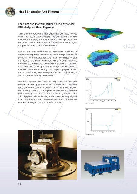
Head Expander And Fixtures<br />
Load Bearing Platform (guided head expander)<br />
FEM designed Head Expander<br />
<strong>TIRA</strong> offer a wide range of head expander, L and T-type fixtures,<br />
cubes and special support systems. The latest software for FEM<br />
calculation and analysis is used so that customers get specifically<br />
designed fixture assemblies with optimized and predicted dynamic<br />
performance to produce the best result.<br />
Fixtures are often main items of application conditions in<br />
industrial testing where specimens are tested to high standards of<br />
precision. This means that the fixture has to be optimized for both<br />
the specimen and the test parameters. Many customers, however,<br />
can't do these sophisticated calculations to produce a suitable fixture.<br />
<strong>TIRA</strong> has faced up to this challenge and will develop,<br />
calculate and manufacture any type of special-purpose fixtures<br />
for your application, with the emphasis on minimizing its weight<br />
and optimize its dynamic performance.<br />
Monobase systems with horizontal slip table and vertically<br />
guided load bearing platform make it possible to test extremely<br />
large and heavy loads in direction of x, y and z axis. Specialdesigned<br />
slip tables and loading bearing platforms are available<br />
with a working area of max. of 2,000 mm x 2,000 mm (78 x<br />
78"). Sip plate and load bearing platform are accurately aligned<br />
in a common base frame. Conversion from horizontal to vertical<br />
operation is easy and takes a minimum of time.<br />
20
<strong>TIRA</strong> head expanders are manufactured from magnesium and<br />
provide an expansion of the armature table up to a ratio of 2:1.<br />
The unique design of the head expanders allows tests up to<br />
2,000 Hz. Head Expanders especially provided with 'vibrodamp'<br />
can be subjected to test frequencies above 1,000 Hz. This<br />
damping process reduces amplification of upper frequency resonances.<br />
Apart from the range of standard head expanders <strong>TIRA</strong> also<br />
offer customer engineered fixtures for round, square or rectangular<br />
working areas.<br />
CIRCULAR VERSION without vibrodamp<br />
Size Typ Armature Height Weight<br />
mm inch mm/ø inch/ø mm inch kg lb<br />
250 10<br />
THR 25-120<br />
THR 25-180<br />
120<br />
180<br />
4.7<br />
7.1<br />
80<br />
80<br />
3.1<br />
3.1<br />
3.7<br />
4.3<br />
8.2<br />
9.5<br />
300 12<br />
THR 30-180<br />
THR 30-220<br />
180<br />
220<br />
7.1<br />
8.7<br />
80<br />
80<br />
3.1<br />
3.1<br />
5.6<br />
26.7<br />
12.3<br />
58.9<br />
400 16<br />
THR 40-180<br />
THR 40-220<br />
180<br />
220<br />
7.1<br />
8.7<br />
120<br />
120<br />
4.7<br />
4.7<br />
10.0<br />
12.0<br />
22.0<br />
26.5<br />
THR 50-180 180 7.1 150 5.9 20.0 44.1<br />
500 20 THR 50-220 220 8.7 150 5.9 24.0 52.9<br />
THR 50-330 340 13.4 150 5.9 28.0 61.7<br />
THR 60-180 180 7.1 210 8.3 29.0 63.9<br />
600 24 THR 60-220 220 8.7 210 8.3 40.0 88.2<br />
THR 60-330 340 13.4 210 8.3 48.0 105.8<br />
THR 80-330 340 13.4 230 9.1 69.0 152.1<br />
800 31 THR 80-440 440 17.3 245 9.6 82.0 180.8<br />
THR 80-640 640 25.2 180 7.1 67.0 147.7<br />
1000 39<br />
THR 100-440<br />
THR 100-640<br />
440<br />
640<br />
17.3<br />
25.2<br />
305<br />
235<br />
12.0<br />
9.3<br />
143.0<br />
126.0<br />
315.3<br />
277.8<br />
SQUARE VERSION without vibrodamp<br />
Size Typ Armature Height Weight<br />
mm inch mm/ø inch/ø mm inch kg lb<br />
250 x 250 10 x 10 THS 25-120 120 4.7 100 3.9 6.9 15.2<br />
300 x 300 12 x 12 THS 30-120 120 4.7 100 3.9 7.1 15.7<br />
THS 30-180 180 7.1 100 3.9 7.55 16.6<br />
400 x 400 16 x 16 THS 40-180 180 7.1 100 3.9 16 35.3<br />
THS 40-220 220 8.7 100 3.9 13.5 29.8<br />
500 x 500 20 x 20 THS 50-180 180 7.1 120 4.7 23.5 51.8<br />
THS 50-220 220 8.7 150 5.9 28 61.7<br />
THS 50-330 340 13.4 180 7.1 34 75.0<br />
600 x 600 24 x 24 THS 60-180 180 7.1 180 7.1 36 79.4<br />
THS 60-220 220 8.7 180 7.1 39 86.0<br />
THS 60-330 340 13.4 180 7.1 54 119.0<br />
THS 60-440 440 17.3 180 7.1 54 119.0<br />
800 x 800 31 x 31 THS 80-440 440 17.3 180 7.1 95 209.4<br />
THS 80-640 640 25.2 120 4.7 80 176.4<br />
1000 x 1000 39 x 39 THS 100-440 440 17.3 200 7.9 134 295.4<br />
THS 100-640 640 25.2 140 5.5 153 337.3<br />
Head Expanders<br />
CIRCULAR VERSION with vibrodamp<br />
Size Typ Armature Height Weight<br />
mm inch mm/ø inch/ø mm inch kg lb<br />
400 16<br />
THR 40-180V<br />
THR 40-220V<br />
180<br />
220<br />
7.1<br />
8.7<br />
120<br />
120<br />
4.7<br />
4.7<br />
15.0*<br />
18.0*<br />
33.1*<br />
39.7*<br />
THR 50-180V 180 7.1 150 5.9 30.0* 66.1*<br />
500 20 THR 50-220V 220 8.7 150 5.9 36.0* 79.4*<br />
THR 50-330V 340 13.4 150 5.9 42.0* 92.6*<br />
THR 60-180V 180 7.1 210 8.3 43.5* 95.9*<br />
600 24 THR 60-220V 220 8.7 210 8.3 60.0* 132.3*<br />
THR 60-330V 340 13.4 210 8.3 72.0* 158.7*<br />
THR 80-330V 340 13.4 230 9.1 103.5* 228.2*<br />
800 31 THR 80-440V 440 17.3 245 9.6 123.0* 271.2*<br />
THR 80-640V 640 25.2 180 7.1 100.5* 221.6*<br />
1000 39<br />
THR 100-440V<br />
THR 100-640V<br />
440<br />
640<br />
17.3<br />
25.2<br />
305<br />
235<br />
12.0<br />
9.3<br />
214.5*<br />
189.0*<br />
472.9*<br />
416.7*<br />
* may vary by 10 %<br />
SQUARE VERSION with vibrodamp<br />
Size Typ Armature Height Weight<br />
mm inch mm/ø inch/ø mm inch kg lb<br />
300 x 300 12 x 12 THS 30-120V 120 4.7 100 3.9 17.0* 37.5*<br />
THS 30-180V 180 7.1 100 3.9 24.0* 52.9*<br />
400 x 400 16 x 16 THS 40-180V 180 7.1 100 3.9 20.3* 44.8*<br />
THS 40-220V 220 8.7 120 4.7 35.3* 77.8*<br />
500 x 500 20 x 20 THS 50-180V 180 7.1 150 5.9 42.0* 92.6*<br />
THS 50-220V 220 8.7 180 7.1 51.0* 112.4*<br />
THS 50-330V 340 13.4 180 7.1 54.0* 119.0*<br />
600 x 600 24 x 24 THS 60-180V 180 7.1 180 7.1 58.5* 129.0*<br />
THS 60-220V 220 8.7 180 7.1 81.0* 178.6*<br />
THS 60-330V 340 13.4 180 7.1 81.0* 178.6*<br />
THS 60-440V 440 17.3 180 7.1 81.0* 178.6*<br />
800 x 800 31 x 31 THS 80-440V 440 17.3 180 7.1 142.5* 314.2*<br />
THS 80-640V 640 25.2 120 4.7 120.0* 264.6*<br />
1000 x 1000 39 x 39 THS 100-440 440 17.3 200 7.9 201.0* 443.1*<br />
THS 100-640 640 25.2 140 5.5 229.5* 506.0*<br />
* may vary by 10 %<br />
21
Fixtures<br />
To perform multi-axis vibration testing, L & T fixtures or cubic<br />
designs, as well as specially engineered support fixtures can be<br />
produced to meet any particular test requirements.<br />
The unique design of the fixtures allows tests up to 2,000 Hz.<br />
<strong>TIRA</strong> also offer customer engineered fixtures for round, square or<br />
rectangular working areas.<br />
22<br />
L-fixtures<br />
L - Fixture<br />
Type Size mm Size inch<br />
Fix-L 20 200 x 200 mm 8 x 8 inch<br />
Fix-L 26 260 x 260 mm 10 x 10 inch<br />
Fix-L 30 300 x 300 mm 12 x 12 inch<br />
Fix-L 40 400 x 400 mm 16 x 16 inch<br />
T-fixtures<br />
T - Fixture<br />
Type Size mm Size inch<br />
Fix-T 20 200 x 200 mm 8 x 8 inch<br />
Fix-T 26 260 x 260 mm 10 x 10 inch<br />
Fix-T 30 300 x 300 mm 12 x 12 inch<br />
Fix-T 40 400 x 400 mm 16 x 16 inch<br />
Cube<br />
Cube - Fixture<br />
Type Size mm Size inch<br />
Fix-C 20 200 x 200 mm 8 x 8 inch<br />
Fix-C 25 250 x 250 mm 10 x 10 inch<br />
Fix-C 30 300 x 300 mm 12 x 12 inch<br />
Fix-C 40 400 x 400 mm 16 x 16 inch
The Quality, reliability, and safety of products require utmost care<br />
from the concept to the end-user.<br />
To meet this pretentious requirement, one nowadays investigates<br />
the interactions between objects and their direct or indirect<br />
environment by means of environment testing systems. Based<br />
upon such experience, Products are developed with reference to<br />
specific applications as well as high quality and long lifetime<br />
achieved. Such flaws as material and production faults can be<br />
detected early and costly breakdowns or callback actions<br />
avoided.<br />
In practical use, the products are exposed to various environmental<br />
influences at the same time such as e.g. temperature,<br />
humidity, vibrations, and transport loads. User-specific one-sided<br />
test systems are used as combinations in the test setup and linked<br />
to form full test systems. <strong>TIRA</strong> delivers full test systems from one<br />
hand.<br />
Production program<br />
• Chambers for simulating environmental conditions<br />
(temperature, air humidity, pressure, irradiation, vibration)<br />
• Temperature shock testing installations<br />
(air/air, liquid/liquid, horizontal, vertical)<br />
• Corrosion test chambers and devices for artificial weathering<br />
(salt nebulization, air pollutants, ultraviolet irradiation<br />
• Combined vibration chamber systems<br />
(complete vertical and horizontal solutions)<br />
• Passable special installations<br />
(air-bag test chambers, sunlight simulation, open-plan cells)<br />
Temperature/Climatic <strong>Test</strong> <strong>Systems</strong><br />
With <strong>TIRA</strong>vibro a series of vibration testing<br />
chambers for combined testing procedures<br />
under climatic and thermic influences and<br />
mechanical and dynamic loading was developed.<br />
The climate- and temperature-testing chambers<br />
can be adapted to any vertical and horizontal<br />
vibration system. They are especially optimised<br />
for the operation with <strong>TIRA</strong> vibration testing<br />
installations and for the integration in complete<br />
<strong>TIRA</strong> systems. Due to the integration in system<br />
solutions the testing chamber and the shaker<br />
can by operated by a common test software<br />
(TEC). Exchangeable or fixed base plates are<br />
the interface for coupling the shaker to the test<br />
chamber. In dependence on the kind of vibration<br />
test a permanently installed base plate or<br />
two flexible base plates are inserted into the<br />
test chamber.<br />
� �<br />
�<br />
� Integration of vibration<br />
generator into<br />
climatic chamber<br />
� Head extender<br />
� Integration of slip<br />
table into climatic<br />
cabinet<br />
23
Temperature/Climatic <strong>Test</strong> <strong>Systems</strong><br />
If combined test problems with vibration and temperature conditions<br />
have to be solved we offer our customers complete solutions.<br />
With the help of the <strong>TIRA</strong> software for controlling the vibration<br />
testing installation and the vibration climatic chamber we have<br />
developed a comfortable software interface.<br />
Due to the simple operation of the software <strong>TIRA</strong> offers its<br />
customers a perfect solution for long-time tests. The simple entry<br />
of test parameters and the combination with test profiles of the<br />
vibration control system make a fast and individual test preparation<br />
possible.<br />
Seal test cabinet Head extender<br />
Thermobarrier<br />
The outstandingly designed screen presentation offers the customer<br />
a constant survey of<br />
the temperature testing the vibration testing<br />
o current test time o current test time<br />
o current temperature o current acceleration<br />
o current humidity values o current test rate<br />
o status of control unit<br />
The flexible drawing-up of reports offers you the possibility to display<br />
the test procedure graphically and in table form.<br />
24<br />
Climatic cabinet leadthroughs<br />
Size Height Weight<br />
mm inch mm inch kg lb<br />
120 4.7 160 6.3 2.5 5.5<br />
180 7.1 160 6.3 4 8.8<br />
220 8.7 160 6.3 5 11.0<br />
340 13.4 160 6.3 7.4 16.3<br />
440 17.3 160 6.3 20.8 45.9<br />
640 25.2 160 6.3 40.2 88.6<br />
Thermobarriers for fixtures<br />
Size Height Weight<br />
mm inch mm inch kg lb<br />
120 4.7 20 0.8 0.5 1.1<br />
180 7.1 20 0.8 1.1 2.4<br />
220 8.7 20 0.8 1.7 3.7<br />
340 13.4 20 0.8 3.8 8.4<br />
440 17.3 20 0.8 7.3 16.1<br />
640 25.2 20 0.8 15.4 34.0<br />
Thermobarriers for sliding plates<br />
Size Height Weight<br />
mm inch mm inch kg lb<br />
305 x 305 12 x 12 20 0.8 4.5 9.9<br />
458 x 458 18 x 18 20 0.8 10.1 22.3<br />
508 x 508 20 x 20 20 0.8 12.4 27.3<br />
610 x 610 24 x 24 20 0.8 17.9 39.5<br />
762 x 762 30 x 30 20 0.8 27.9 61.5<br />
915 x 915 36 x 36 20 0.8 40.2 88.6<br />
991 x 991 39 x 39 20 0.8 47.1 103.8<br />
1200 x 1200 48 x 48 20 0.8 72.1 159.0<br />
1500 x 1500 60 x 60 20 0.8 112.5 248.0<br />
1800 x1800 70 x 70 20 0.8 162.4 358.0<br />
Thermobarriers for clamping tables<br />
Size Height Weight<br />
mm inch mm inch kg lb<br />
300 x300 12 x 12 20 0.8 4.3 9.5<br />
400 x 400 16 x 16 20 0.8 7.7 17.0<br />
500 x 500 20 x 20 20 0.8 12 26.5<br />
600 x 600 24 x 24 20 0.8 17.3 38.1<br />
800 x 800 31 x 31 20 0.8 30.7 67.7<br />
1000 x 1000 39 x 39 20 0.8 51.1 112.7<br />
Thermobarriers for clamping tables<br />
Size Height Weight<br />
mm inch mm inch kg lb<br />
250 9.8 20 0.8 2.4 5.3<br />
300 11.8 20 0.8 3.4 7.5<br />
400 15.8 20 0.8 6 13.2<br />
500 19.7 20 0.8 9.4 20.7<br />
600 23.6 20 0.8 13.6 30.0<br />
800 31.5 20 0.8 24.1 53.1<br />
1000 39.4 20 0.8 37.7 83.1
Blowers are used for cooling the shakers. <strong>TIRA</strong> exclusively offers<br />
radial-flow fans that dispose of an above-average cooling performance<br />
in comparison with axial blowers.<br />
In addition to this, silencers for damping the blow-off noise are<br />
offered.<br />
An aerated sound-absorbing chamber is offered for installing the<br />
cooling blower in closed rooms. The low-maintenance blower can<br />
also be installed outdoors.<br />
Blower Engine Dimension Air Hose Weight Soundpressure<br />
Designation air amount Performance Phase Voltage Frequency A/B/C Diameter length Level<br />
m 3 /h kW V Hz mm inch mm inch m inch kg lb dB(A)<br />
SB 0080 80 0.37 1 115/230 50 246/256/247 9.7/10.1/9.7 40 1.57 3 118 10 22.0 58<br />
SB 0140 140 1.1 1 115/230 50 285/269/302 11.2/10.6/11.9 50 1.97 3 118 16 35.3 63<br />
SB 0200 210 1.3 3 230/400 50 334/314/337 13.1/12.4/13.3 60 2.36 5 197 20 44.1 66<br />
SB 0310 315 2.2 3 230/400 50 381/377/384 15/14.8/15.1 60 2.36 5 197 29 63.9 70<br />
SB 0530 500 5.5 3 230/400 50 498/496/516 19.6/19.5/20.3 60 2.36 5 197 112 246.9 71<br />
SD 9 870 7.0 3 400 50 560/695/650 22/27.4/25.6 100 3.94 5 197 104 229.3 84<br />
SD120 1140 11.5 3 400 50 600/676/675 23.6/26.6/26.6 100 3.94 5 197 131 288.8 84<br />
RD 8 3300 5.5 3 400 50 845/540/915 33.3/21.3/36 150 5.91 5 197 95 209.4 98<br />
HRD 7/FU/11 5820 11 3 400 50 611/692/700 24.1/27.2/27.6 150 5.91 5 197 157 346.1 98<br />
HRD 7/FU/20 5820 20 3 400 50 611/692/700 24.1/27.2/27.6 150 5.91 5 197 157 346.1 98<br />
Type: HRD<br />
Type: SE/SD<br />
A<br />
A<br />
C<br />
C<br />
B<br />
B<br />
enclosure<br />
Silencer<br />
Silencer<br />
Blower<br />
25
Linear Power Amplifiers<br />
<strong>TIRA</strong> offers a new series of analogue amplifiers with a rated<br />
sinusoidial power output up to 2,000 VA. The modules control all<br />
permanent magnetic shakers as well as shakers in connection<br />
with an internal field excitation up to 1,600 N.<br />
These amplifiers equipped with highly-advanced MOSFET transistors<br />
can be run in the current or the voltage mode, as desired.<br />
The amplifiers are user-friendly because of their background-lit<br />
multifunctional display.<br />
A safety management system monitors such functions like temperature,<br />
overcurrent and overtravel and avoids the destruction of<br />
the amplifier in case of short circuit.<br />
A high signal-to-noise ratio and a low distortion factor are<br />
outstanding features. Selectable ranges of operating voltage and<br />
current range limiting are preconditions for the fact that <strong>TIRA</strong><br />
amplifiers can be readily adapted to other shakers from other<br />
manufactures.<br />
According to standard, the amplifiers are designed for connecting<br />
the electronic zero-adjustment control unit TMC. Thus, even<br />
with small shakers a load compensation for achieving the nominal<br />
vibration<br />
Amplifer BAA60 BAA120 BAA500<br />
KVA Ratings 60 VA 120 VA 500 VA<br />
Frequenzy Range DC- 20 kHz DC- 20 kHz DC- 20 kHz<br />
Voltage-/Current mode yes/no yes/yes yes/yes<br />
Voltage, max. 16 V 22 V 45 V<br />
Current, max. 3.8 A 5.5 A 11.2 A<br />
Load Resistance 4 Ohm 4 Ohm 4 Ohm<br />
Input Voltage < 5V < 5V < 5V<br />
Distortion < 0.1 % < 0.1 % < 0.1 %<br />
Signal to Noise Ratio > 90 dB > 90 dB > 90 dB<br />
Field Supply no no no<br />
Voltage, max. – – –<br />
Current, max. – – –<br />
Weight (kg) (lb) 12 26.5 15 33.1 25 55.1<br />
Size (WxHXD) (mm) (inch) 483 x 90 x 450 19 x 3.5 x 17.7 483 x 90 x 450 19 x 3.5 x 17.7 483 x 90 x 450 19 x 3.5 x 17.7<br />
Interlocks Overload Overload Overload<br />
Temperature Temperature Temperature<br />
Clipping Clipping Clipping<br />
Amplifer BAA1000 BAA1000-E BAA 2000-E<br />
KVA Ratings 1000 VA 1000 VA 2000 VA<br />
Frequenzy Range DC- 20 kHz DC- 20 kHz DC- 4 kHz<br />
Voltage-/Current mode yes/yes yes/yes yes/opt.<br />
Voltage, max. 70 V 70 V 110 V<br />
Current, max. 18 A 18 A 18 A<br />
Load Resistance 4 Ohm 4 Ohm 4 Ohm<br />
Input Voltage < 5V < 5V 1/2/5/10 V<br />
Distortion < 0.1 % < 0.1 % < 0.1 %<br />
Signal to Noise Ratio > 90 dB > 90 dB > 70 dB<br />
Field Supply no yes yes<br />
Voltage, max. – 30 V 100 V<br />
Current, max. – 5 A 6 A<br />
Weight (kg) (lb) 45 99.2 72 158.7 230 507.1<br />
Size (WxHXD) (mm) (inch) 483 x 190 x 600 19 x 7.5 x 23.6 483 x 320x 600 19 x 12.6 x 23.6 600 x 1600 x 800 23.6 x 63 x 31.5<br />
Interlocks Overload Overload Overload<br />
Temperature Temperature Temperature<br />
Clipping Clipping Clipping<br />
Output stage<br />
26
<strong>TIRA</strong> power amplifiers are built with cascadable 6 kVA modules,<br />
designed according to the latest technological developments.<br />
Highly-advanced MOSFET power transistors combined with a<br />
complete module management guarantee a high output power at<br />
highest safety.<br />
On the LCD-Touch screen display the module status with current<br />
indication, the percental modulation of the modules and the error<br />
diagnostics are shown. A safety monitoring unit protects the<br />
amplifier from short circuit and from a possible destruction of the<br />
modules.<br />
Error indication and system parameters in plain text increase the<br />
availability due to a faster diagnostics. The high clock frequency<br />
of 80 kHz realizes test frequencies of more than 4,000 Hz without<br />
any decrease in power possible. The cascading of the modules<br />
allows an amplifier design up to 240 kVA at low floor space<br />
requirement.<br />
The output voltage of the modules can be modified so that <strong>TIRA</strong><br />
amplifiers can be adapted to almost all shakers existing on the<br />
market.<br />
Digital Power Amplifiers<br />
Amplifier A51260 A 51312 A 51324 A 52312<br />
KVA Ratings 6 KVA 12 kVA 24 KVA 12 KVA<br />
Frequenzy Range DC - 4 kHz DC - 4 kHz DC - 4 kHz DC - 4 kHz<br />
Voltage, max. 110 V 110 V 110 V 110 V<br />
Current, max. 55 A 110 A 220 A 110 A<br />
Load Resistance 2 Ohm 1 Ohm 2 Ohm 1 Ohm<br />
Input Voltage 1/2/5/10 V 1/2/5/10 V 1/2/5/10 V 1/2/5/10 V<br />
Distortion < 1 % < 1 % < 1 % < 1 %<br />
Signal to Noise Ratio > 70 dB > 70 dB > 70 dB > 70 dB<br />
Field Supply yes yes yes yes<br />
Voltage, max. 100/180V 180 V 180 V 280 V<br />
Current, max. 6 A 6 A 6 A 6 A<br />
Weight (Kg) / (lb) 230 507.1 280 617.3 350 771.6 290 639.3<br />
Size (W x H x D) (mm)/(inch) 600 x 1600 x 800 23.6 x 63.0 x 31.5 600 x 1600 x 800 23.6 x 63.0 x 31.5 600 x 2100 x 800 23.6 x 82.6 x 31.5 600 x 1600 x 800 23.6 x 63.0 x 31.5<br />
Interlocks Overload Overload Overload Overload<br />
Temperature Temperature Temperature Temperature<br />
Clipping Clipping Clipping Clipping<br />
Output stage Output stage Output stage Output stage<br />
Amplifier A 52318 A 52324 A 52330 A 53312<br />
KVA Ratings 18 kVA 24 kVA 30 kVA 12 kVA<br />
Frequenzy Range DC - 4 kHz DC - 4 kHz DC - 4 kHz DC - 4 kHz<br />
Voltage, max. 110 V 110 V 110 V 110 V<br />
Current, max. 150 A 220 A 330 A 110 A<br />
Load Resistance 0.7 Ohm 0.7 Ohm 0.5 Ohm 1 Ohm<br />
Input Voltage 1/2/5/10 V 1/2/5/10 V 1/2/5/10 V 1/2/5/10 V<br />
Distortion < 1 % < 1 % < 1 % < 1 %<br />
Signal to Noise Ratio > 70 dB > 70 dB > 70 dB > 70 dB<br />
Field Supply yes yes yes yes<br />
Voltage, max. 280 V 280 V 280 V 140 V<br />
Current, max. 6 A 6 A 6 A 8 A<br />
Weight (Kg) / (lb) 360 793.7 400 881.8 480 1058.2 290 639.3<br />
Size (W x H x D) (mm)/(inch) 600 x 1600 x 800 23.6 x 63.0 x 31.5 600 x 2100 x 800 23.6 x 82.6 x 31.5 600 x 2100 x 800 23.6 x 82.6 x 31.5 600 x 1600 x 800 23.6 x 63.0 x 31.5<br />
Interlocks Overload Overload Overload Overload<br />
Temperature Temperature Temperature Temperature<br />
Clipping Clipping Clipping Clipping<br />
Output stage Output stage Output stage Output stage<br />
27
Digital Power Amplifiers<br />
<strong>TIRA</strong> power amplifiers are built with cascadable 6 kVA modules,<br />
designed according to the latest technological developments.<br />
Highly-advanced MOSFET power transistors combined with a<br />
complete module management guarantee a high output power at<br />
highest safety.<br />
On the LCD-Touch screen display the module status with current<br />
indication, the percental modulation of the modules and the error<br />
diagnostics are shown. A safety monitoring unit protects the<br />
amplifier from short circuit and from a possible destruction of the<br />
modules.<br />
Error indication and system parameters in plain text increase the<br />
availability due to a faster diagnostics. The high clock frequency<br />
of 80 kHz realizes test frequencies of more than 4,000 Hz without<br />
any decrease in power possible. The cascading of the modules<br />
allows an amplifier design up to 240 kVA at low floor space<br />
requirement.<br />
The output voltage of the modules can be modified so that <strong>TIRA</strong><br />
amplifiers can be adapted to almost all shakers existing on the<br />
market.<br />
Amplifier A 53318 A 53330 A 53342 A 54324<br />
KVA Ratings 18 kVA 30 kVA 42 kVA 24 kVA<br />
Frequenzy Range DC - 4 kHz DC - 4 kHz DC - 4 kHz DC - 4 kHz<br />
Voltage, max. 110 V 110 V 110 V 110 V<br />
Current, max. 165 A 275 A 380 A 220 A<br />
Load Resistance 0.7 Ohm 0.5 Ohm 0.3 Ohm 0.5 Ohm<br />
Input Voltage 1/2/5/10 V 1/2/5/10 V 1/2/5/10 V 1/2/5/10 V<br />
Distortion < 1 % < 1 % < 1 % < 1 %<br />
Signal to Noise Ratio > 70 dB > 70 dB > 70 dB > 70 dB<br />
Field Supply yes yes yes yes<br />
Voltage, max. 140 V 140 V 140 V 70 V<br />
Current, max. 8 A 8 A 8 A 100 A<br />
Weight (Kg) / (lb) 380 837.8 490 1080.3 480 1058.2 350 771.6<br />
Size (W x H x D) (mm)/(inch) 600 x 1600 x 800 23.6 x 63.0 x 31.5 600 x 2100 x 800 23.6 x 82.6 x 31.5 600 x 2100 x 800 23.6 x 82.6 x 31.5 600 x 2100 x 800 23.6 x 82.6 x 31.5<br />
Interlocks Overload Overload Overload Overload<br />
Temperature Temperature Temperature Temperature<br />
Clipping Clipping Clipping Clipping<br />
Output stage Output stage Output stage Output stage<br />
Amplifier A 54336 A 54342 A 54372 A 54420<br />
KVA Ratings 36 kVA 42 kVA 72 kVA 192 kVA<br />
Frequenzy Range DC - 4 kHz DC - 4 kHz DC - 4 kHz DC - 4 kHz<br />
Voltage, max. 110 V 110 V 110 V 140 V<br />
Current, max. 330 A 385 A 660 A 1320 A<br />
Load Resistance 0.3 Ohm 0.3 Ohm 0.3 Ohm 0.3 Ohm<br />
Input Voltage 1/2/5/10 V 1/2/5/10 V 1/2/5/10 V 1/2/5/10 V<br />
Distortion < 1 % < 1 % < 1 % < 1 %<br />
Signal to Noise Ratio > 70 dB > 70 dB > 70 dB > 70 dB<br />
Field Supply yes yes yes yes<br />
Voltage, max. 100 V 100 V 100 V<br />
Current, max. 90 A 90 A 90 A<br />
Weight (Kg) / (lb) 540 1190.5 600 1322.8 750 1653.5 950 2094.4<br />
Size (W x H x D) (mm)/(inch) 600 x 2100 x 800 23.6 x 82.6 x 31.5 600 x 2100 x 800 23.6 x 82.6 x 31.5 600 x 2100 x 800 23.6 x 82.6 x 31.5 1800 x 2100 x 800 23.6 x 82.6 x 31.5<br />
Interlocks Overload Overload Overload Overload<br />
Temperature Temperature Temperature Temperature<br />
Clipping Clipping Clipping Clipping<br />
Output stage Output stage Output stage Output stage<br />
28
The Sine Controller Model SVC 01 incorporates the latest in<br />
microprocessor technology to provide an economical solution to<br />
modern sinusoidal vibration testing requirements with a remarkably<br />
convenient operator interface. A dual microprocessor<br />
design ensures that all commands bring immediate control<br />
response without degrading the performance of the testing<br />
system. DSP controlled digital synthesis and filtering insures that<br />
the SVC 01 has the performance specifications found only in the<br />
best controllers available.<br />
Two channel acceleration input meets the requirements for<br />
average control of large shakers, slip plates or large fixtures.<br />
The difference output makes transfer function determination and<br />
calibration tests as easy as running a simple sine test. Flexible<br />
programming allows internal storage of up to four independent<br />
1, 2, 3 or 4 level test profiles. Stored test profiles are easy to<br />
modify or replace and are maintained internally when the power<br />
is removed. This feature eliminates the need for external disks or<br />
memory cards and there are no batteries to wear down or replace.<br />
Large displays indicate the frequency, acceleration, and<br />
displacement at all times without the need to manually switch the<br />
display function after a cross-over. A programmable test cycle<br />
counter keeps track of the accumulated test time and can be set<br />
to terminate the test after a specific number of test sweep cycles.<br />
Optional the SVC 01 can be controlled remotely by PC via serial<br />
interface (RS 232, function includes programming and data transfer)<br />
Features:<br />
• Wide frequency range and high resolution:<br />
2.0 Hz to 6550 Hz with 0.1 resolution.<br />
• Two independent input channels/amplifiers. o<br />
• Frequency, acceleration and displacement with test cycle<br />
counter displayed on LCD display.<br />
• Control modes: Channel 1, Channel 2 or Average<br />
(Channel 1 + Channel 2)<br />
• Analysis data can be copied to a PC and displayed/printed<br />
as graphs or inclusion on other Windows based applications.<br />
• Convenient user interface: requires short documentation to set<br />
or run.<br />
• Integral input amplifier with adjustable sensitivity and current<br />
source accepts voltage acceleration signals or direct ICP<br />
accelerometer inputs.<br />
• Four program storage in internal non-volatile memory facilitates<br />
often used test.<br />
Digital Sine Control System<br />
29
<strong>Vibration</strong> Control System<br />
For sine, random, shock, mixed-mode<br />
and road simulation<br />
The computer-aided vibration control system meets all requirements<br />
for an advanced shaker control. It combines a highly-developed<br />
and powerful DSP hardware with a personal computer that<br />
is simple to operate. The system covers the entire test range with<br />
the modes of operation random, sine, shock and mixed-mode<br />
and offers a simple operation with an outstanding graphic user<br />
environment. Within the control system the PC carries out the test<br />
preparation, the indication of the test data and the very flexible<br />
report generation.<br />
30<br />
Sine wave<br />
Random<br />
Shock<br />
Transient<br />
SRS<br />
Sine wave-on-random<br />
random-on-random<br />
Road simulation
RANGES OF USE<br />
• Quality assurance in sensor production<br />
• Departments for the supervision of measuring instruments in<br />
research and industry as required by ISO 9000<br />
• DKD Calibration laboratories Applications<br />
• Reference calibration of back-to-back sensor<br />
• Working calibration of vibration sensors<br />
• Certification of sensor for fabricating shops, issuing of data<br />
sheets<br />
• Supervision of test equipment as required by ISO 9000 for<br />
sensors calibrators charge amplifiers measuring systems as a<br />
mobile system for testing stationary measuring and testing<br />
equipment in production lines in accordance with ISO 9000<br />
FEATURES<br />
There are three basic modes of operation of the Calibration<br />
System:<br />
• Calibration of vibration sensors by the method of comparing<br />
them with a stable high-precision back-to-back sensor or laser<br />
interferometer.<br />
• Calibration of measuring instruments and systems with indicators<br />
of their own by applying defined values of vibration<br />
quantities a, v, and d.<br />
• Calibration of Calibrators by absolute measurement of vibration<br />
quantities a, v and d.<br />
In these basic modes of operation the systems meets all demands<br />
for precision-class High Tech equipment such as<br />
• High precision - measuring uncertainty is 0.5% under reference<br />
conditions<br />
• Traceability to the national standard if desired, the system can<br />
be supplied with a calibration certificate or test record by the<br />
Physikalisch-Technische Bundesanstalt (PTB) of Germany.<br />
The System also meets all demands for streamlining test procedures:<br />
• Automatic test operation and automatic print-out of a user<br />
specific test record.<br />
• Means for processing measured data using a spread sheet<br />
program.<br />
Calibration report<br />
Calibration System<br />
31
Calibration Shaker<br />
In all fields of industry, in aviation, the automotive industry and in<br />
power stations vibration analyses and measurements for determining<br />
the vibration transmission are increasingly carried out.<br />
A large variety of measuring sensors is necessary to realize such<br />
investigations. These measuring sensors have to be checked for<br />
their accuracy and calibrated in defined time intervals.<br />
As most of the measuring sensors have a large measuring range<br />
and large frequency ranges special shakers for calibrating these<br />
sensors are required.<br />
<strong>TIRA</strong> has risen to this challenge and designed a unique shaker<br />
which meets these requirements. This newly developed shaker is<br />
equipped with a special guide system and a vibration system<br />
made of ceramic material. It is characterized by a very high<br />
utilizable frequency range up to 25 kHz and with the appropriate<br />
measuring equipment it is optimally suitable for professional<br />
calibration applications.<br />
System TV 51110-C TV 51120-C TV 51140-C<br />
Shaker S513-C S514-C S540-C<br />
Amplifier BAA 120 BAA 500 BAA 1000<br />
Blower – SB 0080 SB0140<br />
Metric American Metric American Metric American<br />
Rated peak force (N)/(lbf) Sine/Random 100/50 20/10 200/100 40/20 400/200 90/40<br />
Frequency range (Hz) 40 - 25000 40 - 25000 40 - 25000 40 - 25000 40 - 25000 40 - 25000<br />
Max. rated travel (mm)/(inch) Pk - Pk 4 0.2 4 0.2 4 0.2<br />
Max. velocity (m/s)/(inch/sec) Sine/Random 1.2/1.2 47/47 1.2/1.2 47/47 1.2/1.2 47/47<br />
Max. acceleration (g) Sine/Random 25/19 25/19 51/39 51/39 92/61 92/61<br />
Rated current (A) 5.5 5.5 11.2 11.2 18 18<br />
Nominal impedance (Ohm) 4 4 4 4 4 4<br />
Effective moving mass (kg)/(lb) 0.40 0.88 0.40 0.88 0.44 0.97<br />
Main resonance frequency (Hz) >25000 >25000 >25000 >25000 >19000 >19000<br />
Weight with trunnion (kg)/(lb) 33 72.8 33 72.8 16 35.3<br />
Armature (ø/mm)/(ø/inch) 54 2.1 54 2.1 54 2.1<br />
Cooling (m 3 /h)/(ft 3 /min) – – 40 24 80 47<br />
32
Long stroke Shaker with 100 mm displacement<br />
(pk-pk)<br />
Due to the ever increasing safety requirements the industry develops<br />
more and more sensor technology and components that<br />
have to be tested under extreme stress conditions.<br />
The test parameters are developing up to higher and higher<br />
accelerations in combination with large impact ranges. These<br />
tests cannot be realized with conventional standard systems with<br />
a displacement of 50.8 mm (2").<br />
<strong>TIRA</strong> has met the requirements of the industry to manufacture test<br />
installations that can imitate extreme shock simulations. It developed<br />
a series of long-stroke shakers with a displacement of<br />
100 mm (peak -peak).<br />
Apart from their application in laboratories for testing development<br />
problems the integration of these shakers in complete<br />
production lines has optimally proved.<br />
Long Stroke Shaker<br />
System TV 5550/LSS TV 56263/LSS TV 56280/LSS<br />
Shaker TV 5500/LSS S561/LSS TV 56280/+LSS<br />
Amplifier A 51324 A 52324 A 52330<br />
Blower SB 0310 SD 9 SD 9<br />
Metric American Metric American Metric American<br />
Rated peak force (N)/(lbf) Sine/Random/Shock 4000/4000/8000 900/900/1800 6300/6300/12600 1420/1420/2830 8000/8000/8000 1800/1800/1800<br />
Frequency range (Hz) DC - 1000 DC - 1000 DC - 1000 DC - 1000 DC - 1000 DC - 1000<br />
Max. rated travel (mm)/(inch) Pk - Pk 102 4.0 102 4.0 102 4.0<br />
Overtravel 107 4.21 107 4.21 107 4.21<br />
Mechanical stop 112 4.41 112 4.41 112 4.41<br />
Max. velocity (m/s)/(inch/sec) Sine/Random/Shock 3.0/3.0/4.5 118/118/177 3.0/3.0/4.5 118/118/177 3.0/3.0/4.5 118/118/177<br />
Max. acceleration (g) Sine/Random/Shock 37/37/74 37/37/74 54/54/107 54/54/107 68/68/136 68/68/136<br />
Rated current (A) 220 220 220 220 275 275<br />
Suspension Stiffness (N/mm) (lbf/inch) ** ** ** ** ** **<br />
Effective moving mass (kg)/(lb) 11.0 24.3 12.0 26.5 12.0 26.5<br />
Main resonance frequency (Hz) >2000 >2000 >2000 >2000 >2000 >2000<br />
Weight with trunnion (kg)/(lb) 750 1653 1000 2205 1000 2205<br />
Armature (ø/mm)/(ø/inch) 250 9.8 250 9.8 250 9.8<br />
Cooling (m 3 /h)/(ft 3 /min) 280 165 500 294 500 294<br />
System TV 51010/LSS TV 57315/LSS<br />
Shaker TV 51000/LSS S572/LSS<br />
Amplifier A 53330 A 53342<br />
Blower SD 120 SD 120<br />
Metric American Metric American<br />
Rated peak force (N)/(lbf) Sine/Random/Shock 11000/11000/22000 2470/2470/4950 15000/15000/15000 3370/3370/3370<br />
Frequency range (Hz) DC - 1000 DC - 1000 DC - 1000 DC - 1000<br />
Max. rated travel (mm)/(inch) Pk - Pk 102 4.0 102 4.0<br />
Overtravel 107 4.21 107 4.21<br />
Mechanical stop 112 4.41 112 4.41<br />
Max. velocity (m/s)/(inch/sec) Sine/Random/Shock 3.0/3.0/4.5 118/118/177 3.0/3.0/4.5 118/118/177<br />
Max. acceleration (g) Sine/Random/Shock 80/80/160 80/80/160 96/96/191 96/96/191<br />
Rated current (A) 275 275 385 385<br />
Suspension Stiffness (N/mm) (lbf/inch) ** ** ** **<br />
Effective moving mass (kg)/(lb) 14.0 30.9 16.0 35.3<br />
Main resonance frequency (Hz) >2000 >2000 >2000 >2000<br />
Weight with trunnion (kg)/(lb) 1450 3197 1450 3197<br />
Armature (ø/mm)/(ø/inch) 300 11.8 300 11.8<br />
Cooling (m3 /h)/ (ft3 /min) 500 294 500 294<br />
** Electronic 0 – pointregulation with adjustable stiffness<br />
33
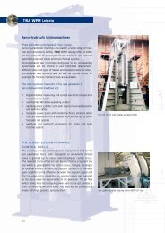
Servohydraulic <strong>Test</strong> <strong>Systems</strong><br />
Servo hydraulic test systems may be used in a wide range of<br />
material and component testing tasks. Therefor, <strong>TIRA</strong>-WPM offers<br />
a modular structured program of servo hydraulic test machines of<br />
the SHM series. Configuration of a servo hydraulic machines can<br />
be carried out according to the unitized construction principle.<br />
<strong>TIRA</strong>-WPM offers various sizes and design various of machine<br />
frames and clamping fixtures for tensile, compressive and bending<br />
tests. Special sample locations, e.g. for fracture mechanics<br />
testing are also available.<br />
Essential features of a new generation of servo hydraulic test<br />
systems are:<br />
• digital-modular electronic measuring and control equipment<br />
based upon a multi-processor system with VME bus<br />
• user-friendly WINDOWS Software<br />
• improved series of test cylinders with significantly better dynamics<br />
and functional safety<br />
• hydraulic power packs with the latest technical solutions<br />
capable of meeting the requirements for reliable and efficient<br />
operation of servo-hydraulic test system.<br />
TEST CYLINDER - A DECISIVE COMPONENT<br />
The standard series comprises a force range of 6 kN to 1000 kN.<br />
The respective sizes can easily be expanded according to<br />
demands. The nominal pressure is 210 bar. <strong>Test</strong> cylinders can<br />
also be delivered with a working pressure of 280 bar.<br />
<strong>Test</strong> cylinders are equipped with:<br />
• hydrostatic bearing with special metallic antifriction coating<br />
• leak proof sealing of piston rod<br />
• inductive displacement transducer<br />
• terminal block for reception from various servo valves of different<br />
dynamics and though put rates<br />
• accumulator and scavenging plate<br />
34
How Does an Exciter Work?<br />
In principle the electromagnetic vibration exciter operates like a<br />
loudspeaker, where the movement is produced by a current passing<br />
through a coil in a magnetic field. The force used to accelerate<br />
the moving element is proportional to the drive current and<br />
the magnetic flux. Therefore by controlling the current, the vibration<br />
level of the exciter can be controlled.<br />
In small exciters the magnetic field is produced by a permanent<br />
magnet, whereas in the larger ones electromagnets are necessary.<br />
The maximum current and the load determines the acceleration<br />
level which can be obtained. At low frequencies, however,<br />
this acceleration level will decrease due to displacement<br />
limitations of the moving element. Resonances in the moving<br />
element will set the upper frequency limit.<br />
The performance of an exciter is presented in a diagram, showing<br />
the maximum acceleration as a function of frequency. With<br />
double logarithmic scales the displacement limit will be represented<br />
by a straight line with a slope of 12 dB/octave. A velocity<br />
limit is often also found, especially with the larger exciters,<br />
and this is indicated by a line with a slope of 6 dB/octave.<br />
The Power Amplifier<br />
The frequency response for an exciter driven by a constant<br />
current will show three regions of different nature. The first two<br />
regions represent the spring-mass system of the moving element<br />
and its suspension with a resonance of typically 20 Hz. In the<br />
third region, typically above 3 kHz for big exciters, axial resonances<br />
in the moving element will occur, setting the upper<br />
operational frequency of the exciter.<br />
A response curve for an exciter with a constant voltage input will<br />
show the same regions of control, but the lower resonance is considerably<br />
damped, giving an easier control of the level. The<br />
voltage control, obtained by a low impedance amplifier is<br />
normally preferred. In some cases, however, a current control will<br />
be advantageous, primarily when the exciter is used as a force<br />
generator or where non-feedback control is required using the<br />
mid frequency range of the exciter. This demands a high impedance<br />
output and therefore amplifiers will often have selectable<br />
impedance outputs.<br />
The Exciter Control<br />
The use of a vibration exciter assumes a constant vibration level<br />
at the table. The frequency response curve is not flat, it contains<br />
resonances, and other resonances will be introduced when a test<br />
object is mounted on the exciter. When used throughout a frequency<br />
range the gain of the amplifier must consequently vary<br />
with frequency.<br />
<strong>Vibration</strong> Basic<br />
This gain is set by a controller, receiving feedback<br />
information from the test object. The main<br />
elements of an exciter control must therefore be<br />
a frequency generator, a vibration meter and a<br />
level controlling 4 circuit.
<strong>TIRA</strong> <strong>Vibration</strong> <strong>Test</strong> <strong>Systems</strong><br />
Member of the <strong>TIRA</strong> Group<br />
� <strong>TIRA</strong> <strong>Vibration</strong> <strong>Test</strong> <strong>Systems</strong><br />
� <strong>TIRA</strong> Balancing <strong>Systems</strong><br />
� <strong>TIRA</strong> Enviromental Simulation<br />
� <strong>TIRA</strong> WPM Leipzig<br />
Eisfelder Straße 23-25<br />
D-96528 Schalkau<br />
Telefon: +49 (0) 367 66 / 280-0<br />
Telefax: +49 (0) 367 66 / 280-99<br />
e-mail: mailinfo@tira-gmbh.de<br />
Internet: www.tira-gmbh.de<br />
Korbach<br />
Paderborn<br />
Marburg<br />
Giessen<br />
Frankfurt am Main<br />
Offenbach<br />
Kassel<br />
Weser<br />
���<br />
Alterations reservations · 10/2004<br />
Fulda<br />
Fulda<br />
��<br />
��<br />
Göttingen<br />
Werra<br />
T h Ÿ r ing e r W a l d<br />
� <strong>TIRA</strong> WPM Leipzig<br />
Gewerbegebiet Wachau<br />
Nordstraße 15<br />
D-04416 Markkleeberg<br />
Telefon: +49 (0) 3 42 97 / 14 35 - 0<br />
Telefax: +49 (0) 3 42 97 / 14 35 -10<br />
E-Mail: info@wpm-leipzig.de<br />
Internet: www.wpm-leipzig.de<br />
www.tirawpm-leipzig.de<br />
Eisenach<br />
���<br />
Schweinfurt<br />
Suhl<br />
���<br />
Nordhausen<br />
Erfurt<br />
Coburg<br />
Weimar<br />
Saale<br />
Bayreuth<br />
Naumburg<br />
Eisfeld SCHALKAU<br />
���<br />
��<br />
Halle<br />
� <strong>TIRA</strong> Enviromental Simulation<br />
Gewerbestraße 19<br />
D-08233 Treuen<br />
Telefon: +49 (0) 374 68 / 68 08-0<br />
Telefax: +49 (0) 374 68 / 68 08-21<br />
e-mail: mailinfo@tira-gmbh.de<br />
Internet: www.tira-gmbh.de<br />
��<br />
Hof<br />
��<br />
Gera<br />
Zwickau<br />
���<br />
LEIPZIG<br />
TREUEN<br />
Chemnitz