

Troubleshooting crude vacuum tower overhead ejector systems
Troubleshooting crude vacuum tower overhead ejector systems
Troubleshooting crude vacuum tower overhead ejector systems

You also want an ePaper? Increase the reach of your titles
YUMPU automatically turns print PDFs into web optimized ePapers that Google loves.
<strong>Troubleshooting</strong> <strong>crude</strong> <strong>vacuum</strong> <strong>tower</strong> <strong>overhead</strong> <strong>ejector</strong> <strong>systems</strong><br />
Use these guidelines to improve performance and product quality<br />
J. R. LINES AND L. L. FRENS, GRAHAM MANUFACTURING CO. INC., BATAVIA, NEW YORK<br />
Routinely surveying <strong>tower</strong> <strong>overhead</strong> <strong>vacuum</strong> <strong>systems</strong> can<br />
improve performance and product quality. These <strong>vacuum</strong> <strong>systems</strong><br />
normally provide reliable and consistent operation.<br />
However, process conditions, supplied utilities, corrosion, erosion<br />
and fouling all have an impact on <strong>ejector</strong> system performance.<br />
Refinery <strong>vacuum</strong> distillation <strong>tower</strong>s use <strong>ejector</strong> <strong>systems</strong> to maintain<br />
<strong>tower</strong> top pressure and remove <strong>overhead</strong> gases (Fig. 1).<br />
However, as with virtually all refinery equipment, performance<br />
may be affected by a number of variables. These variables may act<br />
independently or concurrently. It is important to understand<br />
basic operating principles of <strong>vacuum</strong> <strong>systems</strong> and how performance<br />
is affected by:<br />
• Utilities<br />
• Corrosion and erosion<br />
• Fouling<br />
• Process conditions.<br />
Reputable <strong>vacuum</strong>-system suppliers have service engineers that<br />
will come to a refinery to survey the system and troubleshoot performance<br />
or offer suggestions for improvement. A skilled<br />
<strong>vacuum</strong>-system engineer may be needed to diagnose and remedy<br />
system problems.<br />
UTILITIES<br />
When a <strong>vacuum</strong> system is initially designed, utilities are established<br />
and the most extreme conditions are usually used for the<br />
design basis. Once operating, actual utility supply conditions can<br />
be different than those set at the design stage and vary occasionally.<br />
Important utilities for <strong>ejector</strong> <strong>systems</strong> are motive steam and<br />
cooling water. Motive steam pressure, quality and temperature are<br />
critical variables. Flowrate and inlet temperature are important for<br />
cooling water.<br />
Motive steam conditions. These are very important and have a<br />
direct impact on an <strong>ejector</strong>’s operation. If motive steam supply<br />
pressure falls below design, then the nozzle will pass less steam.<br />
When this happens, the <strong>ejector</strong> is not provided with enough energy<br />
to compress the suction load to the design discharge pressure.<br />
The same problem occurs when the supply motive steam temperature<br />
rises above its design value. Result: Increased specific<br />
volume and, therefore, less steam passes through the nozzle.<br />
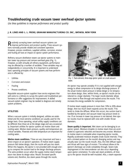
Fig. 1. Twin-element, three-stage <strong>ejector</strong> system on <strong>crude</strong> <strong>vacuum</strong><br />
<strong>tower</strong>.<br />
An <strong>ejector</strong> may operate unstably if it is not supplied with enough<br />
energy to allow compression to its design discharge pressure. If<br />
the actual motive steam pressure is below design or its temperature<br />
above design, then, within limits, an <strong>ejector</strong>’s nozzle can be<br />
rebored to a larger diameter. The larger nozzle diameter allows<br />
more steam to flow through and expand across the nozzle. This<br />
increases the energy available for compression.<br />
If motive steam supply pressure is more than 10% to 20% above<br />
design, then too much steam expands across the nozzle. This<br />
tends to choke the diffuser. When this occurs, less suction load is<br />
handled by the <strong>ejector</strong> and <strong>vacuum</strong> <strong>tower</strong> top pressure tends to<br />
rise. If an increase in <strong>tower</strong> top pressure is not desired, then <strong>ejector</strong><br />
nozzles must be replaced with ones with smaller throat<br />
diameters.<br />
Steam quality is important. Wet steam can be damaging to an<br />
<strong>ejector</strong> system. Moisture droplets in motive steam lines are accelerated<br />
to supersonic velocities and become very erosive. Moisture<br />
in motive steam is noticeable when inspecting <strong>ejector</strong> nozzles.<br />
Rapidly accelerated moisture droplets erode nozzle internals. They<br />
etch a striated pattern on the nozzle’s diverging section and may<br />
actually wear out the nozzle mouth. Also, the inlet diffuser tapers<br />
and throat will have signs of erosion. The exhaust elbow at the<br />
<strong>ejector</strong>’s discharge can erode completely through. Severe tube<br />
impingement in the intercondenser can also occur depending<br />
upon <strong>ejector</strong> orientation. To solve wet steam problems, all lines<br />
up to the <strong>ejector</strong> should be well insulated. Also, a steam separator<br />
Hydrocarbon Processing ® , March 1995 1
Fig. 2. Ejector components and pressure profile.<br />
with a trap should be installed immediately before an <strong>ejector</strong>’s<br />
motive steam inlet connection. In some cases, a steam superheater<br />
may be required.<br />
Wet steam can also cause performance problems. When water<br />
droplets pass through an <strong>ejector</strong> nozzle, they decrease the energy<br />
available for compression. The effect is a decrease in load handling<br />
ability. With extremely wet steam, the <strong>ejector</strong> may even<br />
break operation.<br />
Cooling water. Ejector system intercondensers and intercondensers<br />
are designed to condense steam and condensible<br />
hydrocarbons, and cool non-condensible gases. This occurs at a<br />
pressure corresponding to the preceding <strong>ejector</strong>’s design discharge<br />
pressure and the following <strong>ejector</strong>’s design suction pressure. When<br />
the cooling water supply temperature rises above its design value,<br />
<strong>ejector</strong> system performance is penalized. A rise in cooling water<br />
temperature drives down a condenser’s available log-mean temperature<br />
difference (LMTD). The condenser does not condense<br />
enough and more vapors are carried out with the non-condensible<br />
gases as saturation components. A pressure drop increase across<br />
the condenser is noticeable. The <strong>ejector</strong> following this condenser<br />
cannot handle the increased load at this pressure. Pressure rises<br />
and the preceding <strong>ejector</strong> does not have enough energy to discharge<br />
to the higher pressure. Result: The preceding <strong>ejector</strong><br />
breaks operation and the system may become unstable.<br />
This also occurs if the cooling water flowrate falls below design.<br />
At lower-than-design cooling water flowrates, there is a greater<br />
water temperature rise across a condenser. This also lowers<br />
LMTD and the above situation occurs.<br />
Problems with cooling water normally occur during summer<br />
months. This is when the water is at its warmest and demands on<br />
refinery equipment are highest. If the cooling water flowrate or<br />
temperature is off design then new <strong>ejector</strong>s or condensers may be<br />
required to provide satisfactory operation.<br />
EJECTOR FUNDAMENTALS<br />
The basic operating principle of an <strong>ejector</strong> is to convert pressure<br />
energy into velocity. This occurs with adiabatic expansion of<br />
motive steam across a converging/diverging nozzle from motive<br />
pressure to suction load operating pressure. Supersonic velocity<br />
from the nozzle mouth results. Typically, velocities of mach 3 to 4<br />
are achieved.<br />
In operation, motive steam expands to a pressure below the suction<br />
pressure. This creates a driving force to bring the suction load into<br />
the <strong>ejector</strong>. High-velocity motive steam entrains and mixes with<br />
the suction load gas. The resulting mixture is still supersonic. As<br />
this mixture enters the converging/diverging diffuser, high velocity<br />
is reconverted into pressure. A diffuser’s converging section reduces<br />
velocity as crossflow area is reduced. The diffuser’s throat is<br />
designed to create a normal shock wave. A dramatic increase in<br />
pressure occurs as the flow across the shock wave goes from supersonic<br />
to sonic to subsonic after the shock wave. In the diffuser’s<br />
diverging section, cross-sectional flow area is increased and velocity<br />
is further converted to pressure. Fig. 2 details <strong>ejector</strong> components<br />
and a pressure profile for an <strong>ejector</strong> having a compression ratio in<br />
excess of 2:1.<br />
Ejector <strong>systems</strong> are required to operate over a wide range of conditions—from<br />
very light loads to loads above design. An <strong>ejector</strong><br />
system must stably adapt to all anticipated operating conditions.<br />
Determining the design non-condensable and light-end hydrocarbon<br />
loading is essential for stable operation. Furthermore, an<br />
accurate understanding of system back pressure is important.<br />
Ejector <strong>systems</strong> may be configured a number of different ways to<br />
offer flexibility in handling various feedstocks and differing refinery<br />
operations. A single <strong>vacuum</strong> train with one set of <strong>ejector</strong>s and<br />
condensers has the lowest initial capital cost, but flexibility is limited.<br />
Often, parallel <strong>ejector</strong> trains are installed for each stage. Each<br />
parallel <strong>ejector</strong> will handle a percentage of the total loading. For<br />
example:<br />
• Twin element <strong>ejector</strong>s, each designed for 50% of total load<br />
• Triple element <strong>ejector</strong>s, each designed for 40% of total loading<br />
for 120% capacity<br />
• Twin element, 1 ⁄3: 2 ⁄3 <strong>ejector</strong> trains<br />
• Other configurations.<br />
Parallel <strong>ejector</strong> trains allow one train to be shut down for maintenance<br />
while the column operates at reduced conditions. Also, at<br />
light loadings, a train may be shut down to conserve refinery operating<br />
costs. Fig. 3 shows a typical <strong>vacuum</strong> <strong>tower</strong> <strong>ejector</strong> system<br />
with a triple element <strong>ejector</strong> and first intercondenser. The second<br />
intercondenser and aftercondenser are a single element.<br />
CORROSION AND EROSION<br />
Corrosion may occur in <strong>ejector</strong>s, condensers or <strong>vacuum</strong> piping.<br />
Extreme corrosion can cause holes and air leaks into the system.<br />
This destroys <strong>vacuum</strong> system performance.<br />
Erosion may occur within the <strong>ejector</strong>s. Poor steam quality and<br />
high velocities erode diffuser and motive nozzle internals. An<br />
<strong>ejector</strong> manufacturer will provide certified information that gives<br />
the motive nozzle and diffuser throat design diameters. If a routine<br />
inspection of these parts indicates an increase in<br />
cross-sectional area over 7%, then performance may be compromised<br />
and replacement parts will be necessary.<br />
Hydrocarbon Processing ® , March 1995 2
Corrosion is a result of improperly selected metallurgy. Ensure that<br />
the most appropriate materials are used before replacing parts. A<br />
common corrosion problem occurs when carbon steel tubing is<br />
used in condensers. Although carbon steel may be suitable for the<br />
<strong>crude</strong> feedstock handled, it is not always the best practical choice.<br />
It does offer the initial advantage of lower capital cost. However,<br />
operating problems far outweigh modest up-front savings.<br />
Vacuum <strong>tower</strong>s undergo periods of extended shutdown for routine<br />
maintenance, revamp or other reasons. During this period, a condenser<br />
with carbon steel tubing will be exposed to air and will rust<br />
and develop a scale buildup. When the system starts up, the condensers<br />
are severely fouled. They will not operate as designed and<br />
<strong>vacuum</strong> system operation is compromised. Modest savings in initial<br />
investment for steel tubing is quickly lost with less-thanoptimal<br />
<strong>tower</strong> operations due to rusted and scaled tubing. Vacuum<br />
system manufacturers often caution against using carbon steel tubing.<br />
Fouling. Intercondensers and aftercondensers are subject to fouling<br />
like all other refinery heat exchangers. This may occur on the<br />
tubeside, shellside or both. Fouling deters heat transfer and, at<br />
some point, may compromise system performance.<br />
Cooling <strong>tower</strong> water is most often used as the cooling fluid for <strong>vacuum</strong><br />
condensers. This water is normally on the tubeside. Typical<br />
fouling deposits on tubing internals cause a resistance to heat transfer.<br />
Over a prolonged period of time, actual fouling may exceed the<br />
design value and condenser performance falls short of design.<br />
Vacuum <strong>tower</strong> <strong>overhead</strong> gases, vapors and motive steam are normally<br />
on the condenser’s shellside. Depending on <strong>tower</strong><br />
fractionation and the type of <strong>crude</strong> processed, a hydrocarbon film<br />
may develop on the tube’s outside surface. This film is a resistance<br />
to heat transfer, and over time, this fouling will exceed design.<br />
Once this occurs, condenser performance falls short.<br />
Routine refinery procedures should include periodic cleaning of<br />
condenser bundles. Cleaning procedures must be for the condenser’s<br />
tubeside and shellside. To facilitate shellside cleaning, a<br />
common practice is to specify removable tube bundles (i.e.,<br />
TEMA designation BXU, AXS or AXT).<br />
Fig 4. Typical first-stage <strong>ejector</strong> operating curve.<br />
Fig 3. Typical multi-stage system.<br />
Process conditions. These are very important for reliable <strong>vacuum</strong><br />
system operation. Process conditions used in the design stage are<br />
rarely experienced during operation. Vacuum system performance<br />
may be affected by the following process condition variables that<br />
may act independently or concurrently:<br />
• Non-condensible gas loading, either air leaks or light-end<br />
hydrocarbons<br />
• Condensible hydrocarbons<br />
• Vacuum <strong>tower</strong> loading<br />
• Vacuum system back pressure<br />
• Condenser condensate barometric leg.<br />
Fig. 5. Preferred recycle control scheme to maintain <strong>tower</strong> pressure<br />
at design when handling <strong>overhead</strong>s below design.<br />
Hydrocarbon Processing ® , March 1995 3
Non-condensible loading. Vacuum <strong>systems</strong> are susceptible to<br />
poor performance when non-condensible loading increases above<br />
design. Non-condensible loading to a <strong>vacuum</strong> system consists of<br />
air leaking into the system, light-end hydrocarbons and cracked<br />
gases from the fired heater. The impact of higher-than-design<br />
non-condensible loading is severe. As non-condensible loading<br />
increases, the amount of saturated vapors discharging from the<br />
condenser increases. The <strong>ejector</strong> following a condenser may not<br />
handle increased loading at the condenser’s design operating pressure.<br />
The <strong>ejector</strong> before the condenser is not designed for a higher<br />
discharge pressure. This discontinuity in pressure causes the first<br />
<strong>ejector</strong> to break operation. When this occurs, the system will<br />
operate unstably and <strong>tower</strong> pressure may rapidly rise above design<br />
values.<br />
Non-condensible loadings must be accurately stated. If not, any<br />
<strong>vacuum</strong> system is subject to performance shortcomings. If noncondensible<br />
loadings are consistently above design, then new<br />
<strong>ejector</strong>s are required. New condensers may be required depending<br />
on severity.<br />
Condensible hydrocarbons. Tower <strong>overhead</strong> loading consists of<br />
steam, condensible hydrocarbons and noncondensibles. As different<br />
<strong>crude</strong> oils are processed or refinery operations change, the<br />
composition and amount of condensible hydrocarbons handled<br />
by the <strong>vacuum</strong> system vary. A situation may occur where the condensible<br />
hydrocarbon loading is so different from design that<br />
condenser or <strong>ejector</strong> performance is adversely affected.<br />
Hydrocarbon Processing ® , March 1995 4
This may occur a couple of different ways. If the<br />
condensing profile is such that condensible hydrocarbons<br />
are not condensed as they were designed<br />
to, then the amount vapor leaving the condenser<br />
increases. Ejectors may not tolerate this situation,<br />
resulting in unstable operation.<br />
Another possible effect of increased condensible<br />
hydrocarbon loading is an increased oil film on the<br />
tubes. This reduces the heat-transfer coefficient.<br />
Again, this situation may result in increased vapor<br />
and gas discharge from the condenser. Unstable<br />
operation of the entire system may also result.<br />
To remedy performance shortcomings, new condensers<br />
or <strong>ejector</strong>s may be necessary.<br />
Tower <strong>overhead</strong> loading. In general, a <strong>vacuum</strong> system will track<br />
<strong>tower</strong> <strong>overhead</strong> loading as long as noncondensible loading does<br />
not increase above design. Tower top pressure follows the firststage<br />
<strong>ejector</strong>’s performance curve. Fig. 4 shows a typical<br />
performance curve. At light <strong>tower</strong> <strong>overhead</strong> loads, the <strong>vacuum</strong><br />
system will pull <strong>tower</strong> top operating pressure down below design.<br />
This may adversely affect <strong>tower</strong> operating dynamics and pressure<br />
control may be necessary.<br />
Tower pressure control is possible with multiple element trains.<br />
At reduced <strong>overhead</strong> loading, one or more parallel elements may<br />
be shut off. This reduces handling capacity, permitting <strong>tower</strong><br />
pressure to rise to a satisfactory level. If multiple trains are not<br />
used, recycle control is another possible solution. Here, the discharge<br />
of an <strong>ejector</strong> is recycled to the system suction. This acts as<br />
an artificial load, driving the suction pressure up. With a multiple-stage<br />
<strong>ejector</strong> system, recycle control should be configured to<br />
recycle the load from before the first condenser back to system<br />
suction (Fig. 5). This way, noncondensible loading is not allowed<br />
to accumulate and negatively impact downstream <strong>ejector</strong>s.<br />
System back pressure. Vacuum system back pressure may have<br />
an overwhelming influence on satisfactory performance. Ejectors<br />
are designed to compress to a design discharge pressure. If the<br />
actual discharge pressure rises above design, the <strong>ejector</strong> will not<br />
have enough energy to reach the higher pressure. When this<br />
occurs, the <strong>ejector</strong> breaks operation and there is a sharp increase<br />
in suction pressure.<br />
When back pressure is above design, possible corrective actions are<br />
to lower the system back pressure, rebore the steam nozzle to permit<br />
the use of more motive steam or install a completely new <strong>ejector</strong>.<br />
Operating survey. The most practical way to troubleshoot a <strong>vacuum</strong><br />
system is to perform a pressure and temperature profile while<br />
the system is in normal operation. Then compare the readings<br />
with the origin design criteria. Before performing a survey, it is<br />
critical to have accurate instrumentation like calibrated thermometers,<br />
pressure gauges and an absolute pressure gauge for<br />
<strong>vacuum</strong> readings.<br />
Readings that should be taken include:<br />
• Motive steam pressure and temperature measured as close as<br />
possible to each <strong>ejector</strong>’s inlet<br />
• Suction and discharge pressure and temperature of each <strong>ejector</strong><br />
• Cooling water inlet and outlet temperature of each condenser<br />
• Tubeside pressure drop across each condenser<br />
• Condensate temperature from each condenser, if available.<br />
With these readings, a step-by-step comparison against the original<br />
design criteria should allow a determination of the cause for a<br />
deficiency in the system.<br />
Tables 1 and 2 will help in analyzing the system to determine any<br />
problems. Table 1 pertains to <strong>ejector</strong> performance and the areas<br />
that effect an <strong>ejector</strong>, namely, motive steam pressure and quality,<br />
suction load and discharge pressure. Table 2 relates to condenser<br />
performance.<br />
If there are still questions as to the exact problem after completing<br />
the above evaluation, it is advisable to contact the original<br />
manufacturer or have a qualified <strong>vacuum</strong> service engineer visit the<br />
site to help analyze the system.<br />
CASE HISTORY<br />
Operating survey of a <strong>vacuum</strong> system on a <strong>crude</strong> <strong>tower</strong> in a<br />
South American refinery. Problem: The refiner was dissatisfied<br />
with the <strong>vacuum</strong> <strong>tower</strong> operating pressure. Tower top pressure<br />
exceeded its design value. Table 3 shows the results of the system<br />
operating survey that was conducted.<br />
The system was shut down and equipment inspected.<br />
Dimensionally, the <strong>ejector</strong>s were in satisfactory condition, but the<br />
second-stage <strong>ejector</strong> showed signs of erosion. The second-stage<br />
<strong>ejector</strong> diffuser throat was 4% to 5% larger in diameter than<br />
design. Each <strong>ejector</strong> had a heavy hydrocarbon film on the motive<br />
steam nozzle exterior and air chamber.<br />
Hydrocarbon Processing ® , March 1995 5
The first intercondenser was heavily fouled on the tube and shellside.<br />
The tubeside had an excessive white scale that caused the<br />
high tubeside pressure drop. The shellside had a heavy black film<br />
coating the tubes. This was similar to what was noticed in the<br />
<strong>ejector</strong>s. The secondary condensers had similar fouling deposits.<br />
Solutions: The higher-than-design cooling water temperature<br />
and excessive fouling of the condensers affected condenser performance<br />
to the extent that inadequate condensation was taking<br />
place. The impact of this was with the <strong>ejector</strong>s. Higher vapor<br />
loads exiting the first intercondenser could not be handled by the<br />
second-stage <strong>ejector</strong> at 86 mmHg Abs. This forced the first-stage<br />
<strong>ejector</strong> to break operation resulting in a substantial increase in<br />
<strong>tower</strong> operating pressure.<br />
Quotes were made to replace existing condensers with new ones<br />
having higher design fouling factors and based on higher cooling<br />
water temperature. Once installed, <strong>tower</strong> top pressure was at<br />
design and operation was stable.<br />
THE AUTHORS<br />
James R. Lines is vice president of engineering<br />
for Graham Manufacturing Co., Inc., Batavia,<br />
New York. Since joining Graham in 1984, he<br />
has held positions as an application engineer,<br />
product supervisor and sales engineer focusing<br />
on <strong>vacuum</strong> and heat transfer processes. Mr<br />
Lines holds a BS degree in aerospace engineering<br />
from the University of Buffalo.<br />
Lance L. Frens is a senior contract engineer/<br />
technical services supervisor for Graham<br />
Manufacturing Co., Inc., Batavia, New York.<br />
Since joining Graham in 1967, he has held positions<br />
as a test technician and application engineer.<br />
Mr Frens has 27 years of hands-on experience<br />
surveying, revamping and troubleshooting <strong>vacuum</strong><br />
and heat transfer <strong>systems</strong> worldwide.<br />
Hydrocarbon Processing ® , March 1995 6
Reprinted from March 1995 Hydrocarbon Processing ® 7