Drilling with casing cuts top-hole time, sets length record
Drilling with casing cuts top-hole time, sets length record
Drilling with casing cuts top-hole time, sets length record

Create successful ePaper yourself
Turn your PDF publications into a flip-book with our unique Google optimized e-Paper software.
Originally appeared in World Oil ®<br />
CASING teChNoloGy<br />
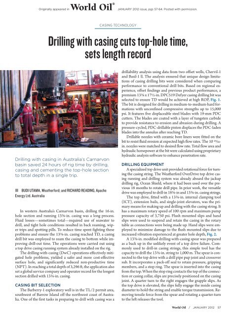
<strong>Drilling</strong> <strong>with</strong> <strong>casing</strong> <strong>cuts</strong> <strong>top</strong>-<strong>hole</strong> <strong>time</strong>,<br />
<strong>sets</strong> <strong>length</strong> <strong>record</strong><br />
<strong>Drilling</strong> <strong>with</strong> <strong>casing</strong> in Australia’s Carnarvon<br />
basin saved 24 hours of rig <strong>time</strong> by drilling,<br />
<strong>casing</strong> and cementing the <strong>top</strong>-<strong>hole</strong> section<br />
to total depth in a single trip.<br />
ŝŝBUDI UTAMA, Weatherford; and RICHARD READING, Apache<br />
Energy Ltd. Australia<br />
In western Australia’s Carnarvon basin, drilling the 16-in.<br />
<strong>hole</strong> section and running 13⅜-in. <strong>casing</strong> was a long process.<br />
Fluid losses—some<strong>time</strong>s total—required use of seawater to<br />
drill, and tight <strong>hole</strong> conditions resulted in back reaming, wiper<br />
trips and spotting pills. To reduce <strong>time</strong> spent fighting these<br />
problems and ensure the 13⅜-in. <strong>casing</strong> reached TD, a <strong>casing</strong><br />
drill bit was employed to ream the <strong>casing</strong> to bottom while improving<br />
drill-out <strong>time</strong>. The operations were carried out using<br />
a <strong>top</strong> drive <strong>casing</strong> running system already installed on the rig.<br />
The drilling-<strong>with</strong>-<strong>casing</strong> (DwC) operations effectively mitigated<br />
<strong>hole</strong> problems, yielded a safer and more cost-effective<br />
surface <strong>hole</strong>, and significantly reduced non-productive <strong>time</strong><br />
(NPT). In reaching a total depth of 3,296 ft, the application also<br />
set a global service company and operator <strong>record</strong> for the longest<br />
section drilled <strong>with</strong> 13⅜-in. <strong>casing</strong>.<br />
CASING BIT SELECTION<br />
The Barberry-1 exploratory well is in the TL/2 permit area,<br />
southwest of Barrow Island off the northwest coast of Australia.<br />
One of the first tasks in preparing to drill <strong>with</strong> <strong>casing</strong> was a<br />
january 2012 issue, pgs 57-64. Posted <strong>with</strong> permission.<br />
drillability analysis using data from two offset wells, Chervil-1<br />
and Basil-1 ll. The analysis ensured that unique design limitations<br />
of <strong>casing</strong> drilling bits were considered when comparing<br />
performance to conventional drill bits. Based on regional experience,<br />
offset findings and previous product performance, a<br />
premium 13⅜ x 17½-in. DPC519 Defyer <strong>casing</strong> drilling bit was<br />
selected to ensure TD would be achieved at high ROP, Fig. 1.<br />
The bit is designed for drilling in medium-to-medium-hard formations<br />
<strong>with</strong> unconfined compressive strengths up to 15,000<br />
psi. It features five displaceable steel blades <strong>with</strong> 19-mm PDC<br />
cutters. The blades are coated <strong>with</strong> a layer of tungsten carbide<br />
to provide resistance to erosion and abrasion during drilling. A<br />
pressure-cycled, PDC-drillable piston displaces the PDC-laden<br />
blades into the annulus after reaching TD.<br />
Drillable nozzles <strong>with</strong> ceramic bore liners were fitted on the<br />
bit to resist fluid erosion at expected high flow rates. The 10 14/32in.<br />
nozzles were matched to desired flow rate. Total flow area and<br />
hydraulic horsepower at the bit were calculated using proprietary<br />
hydraulic analysis software to enhance penetration rate.<br />
DRILLING EQUIPMENT<br />
A specialized <strong>top</strong> drive unit provided rotational force for turning<br />
the <strong>casing</strong> string. The Weatherford OverDrive <strong>top</strong> drive <strong>casing</strong><br />
running and drilling system was already aboard the jackup<br />
drilling rig, Ocean Shield, where it had been used over the previous<br />
18 months to rotate drill pipe. In prior work, the versatile<br />
drive was employed to drill-in 18⅝-in and 13⅜-in. <strong>casing</strong> strings.<br />
The <strong>top</strong> drive, fitted <strong>with</strong> a 13⅜-in. internal clamping tool<br />
(ICT), extension bails, and single-joint elevators, was the primary<br />
means for making up and drilling <strong>with</strong> the <strong>casing</strong> string. It<br />
has a maximum rotary speed of 100 rpm and maximum pump<br />
pressure capacity of 3,750 psi. Flush mounted slips and hand<br />
slips were used to suspend and retain the <strong>casing</strong> in the rotary<br />
table as connections were being made up. Hand slips were employed<br />
to minimize damage to the flush mounted slips due to<br />
increased vibration experienced at greater <strong>hole</strong> depth, Fig. 2.<br />
A 13⅜-in. modified drilling-<strong>with</strong>-<strong>casing</strong> spear was prepared<br />
as a back up in the unlikely event of a <strong>top</strong> drive failure. Commonly<br />
used to drill-in <strong>casing</strong> strings, this simple tool has the<br />
capacity to drill the 13⅜-in. string to 1,000 m. The spear is connected<br />
to the <strong>top</strong> drive <strong>with</strong> a drill pipe pup joint and crossover<br />
sub. It incorporates a pack-off seal to retain pressure, gripping<br />
members, and a s<strong>top</strong> ring. The spear is inserted into the <strong>casing</strong><br />
from the <strong>top</strong>. When the s<strong>top</strong> ring contacts the <strong>top</strong> of the connection<br />
or <strong>casing</strong> collar, slips are precisely positioned on the <strong>casing</strong><br />
joint. A quarter turn to the right engages the grapple slips. As<br />
the <strong>top</strong> drive is elevated, the slips fully engage the inside <strong>casing</strong><br />
diameter to hold the string and enable torque transmission. Removing<br />
tensile force from the spear and rotating a quarter-turn<br />
to the left releases the tool.<br />
World Oil / january 2012 57
CASING teChNoloGy<br />
The float valve was modified for the application. A conventional<br />
poppet-type float valve cannot be used <strong>with</strong> the <strong>casing</strong>drilling<br />
bit, because a ball (2.75 to 3-in. phenolic or aluminum)<br />
is required to cycle the tool and displace the cutting structure.<br />
Instead, the system uses a converted auto-fill float collar rated<br />
at 30 bbl/min for 24 hours using 12 to 12.5-ppg mud <strong>with</strong> 2 to<br />
4% sand content. The auto-fill feature is not required for the<br />
DwC application, so its ball and tube assembly is removed in<br />
the workshop prior to make-up.<br />
CASING AND CONNECTIONS<br />
Casing drilling operations subject the <strong>casing</strong> string to many<br />
stresses, including cyclic fatigue, torsion cycles, and compression<br />
loads. The potential for this moderate wear must be con-<br />
Fig. 1. The 13⅜-in. x 17½-in. OD <strong>casing</strong> bit used offshore australia<br />
is designed for unconfined compressive strengths up to 15,000<br />
psi (1,034 bar). The bit’s five steel blades, fitted <strong>with</strong> 19-mm PDC<br />
cutters, are displaced at TD prior to cementing.<br />
sidered in the <strong>casing</strong> design phase. Casing design must also factor<br />
in burst and collapse loads as well as sealing requirements<br />
after being subjected to these drilling stresses.<br />
Casing and connection specifications for Barberry-1 called<br />
for 13⅜-in., 68 lb/ft, L-80 pipe <strong>with</strong> API buttress connections.<br />
This common <strong>casing</strong> connection does not have a torque shoulder<br />
inside the connector ("J" area), which results in low-torque<br />
transmission capacity. To provide additional torque resistance,<br />
dedicated torque rings were installed in each connection, Fig.<br />
3. The torque ring is a pressure-actuated, metal-to-metal sealing<br />
system. When made up, initial contact force is established<br />
between the pin end and the fulcrum center torque ring. Additional<br />
internal pressure increases sealing contact force beyond<br />
axial loads and pressure of accepted string design limits.<br />
To make up the <strong>casing</strong>, a special insertion tool was used to<br />
install and seat the ring in the "J" area prior to coupling. Makeup<br />
at 5 to 14 rpm requires close attention to torque. When<br />
torque begins to rise quickly, the pin nose has shouldered up<br />
to the rings.<br />
DRILLING OPERATIONS<br />
The 20-in. shoe was drilled out <strong>with</strong> a re-run 17½-in.<br />
roller cone bit, which then drilled on to a depth of 685.73 ft<br />
measured depth from the rotary table (MDRT) or 367.47 ft<br />
drilled. Two of the 36-in. <strong>hole</strong> opener cones were lost in the<br />
previous <strong>hole</strong> section; one was retrieved but the second cone<br />
remained in the <strong>hole</strong>. It was not encountered while drilling the<br />
17½-in. <strong>hole</strong> to 685.73 ft MDRT.<br />
Total losses were encountered while drilling the section,<br />
which is common for the area. At that point, the 17½-in. bot-<br />
58 january 2012 / WorldOil.com<br />
tom-<strong>hole</strong> assembly (BHA) was pulled out of <strong>hole</strong> and the <strong>top</strong><br />
drive system was rigged up to drill-in <strong>with</strong> 13⅜-in. <strong>casing</strong>. A job<br />
safety analysis was conducted to communicate the DwC running<br />
procedure and all associated potential hazards.<br />
The pre-assembled shoe joint and <strong>casing</strong>-drilling bit was<br />
picked up and visually inspected to ensure all PDC cutters and<br />
blades were undamaged. The assembly was then run through<br />
the rotary table and flow tested to confirm that all nozzles were<br />
free of debris. The flush mounted slips were installed. The float<br />
collar joint was made up on the shoe joint and the connection<br />
was thread-locked. Torque rings were installed on the subsequent<br />
<strong>casing</strong> joints, which were made up to 25,000 ft-lb.<br />
The string was washed down to TD at 250 gpm until bottom<br />
was tagged. Casing drilling operations began at 685.73 ft <strong>with</strong>in<br />
recommended parameters of 60 to 100 rpm, 1,200 to 1,400<br />
gpm and 1,000 to 25,000 lb WOB. High-viscosity sweeps were<br />
pumped every joint to deliver effective <strong>hole</strong> cleaning.<br />
Some drilling-induced vibration was noted at surface. To<br />
avoid damage to the flush-mounted slips, they were replaced <strong>with</strong><br />
conventional <strong>casing</strong> hand slips. <strong>Drilling</strong> continued to the section<br />
TD. Maximum drilling parameters were 80 to 100 rpm, 1,400<br />
gpm at 1,350 psi standpipe pressure (SPP), 15,000 to 28,000 lb<br />
WOB and 15,000 to 22,000 ft-lb drilling torque.<br />
Some minor problems were encountered drilling the section.<br />
The <strong>casing</strong> string stalled at 1,426 ft and a 25-bbl high viscosity<br />
sweep was pumped to resume the drilling process. When ROP<br />
dropped to around 98.43 to 164.05 ft/hr and SPP increased to<br />
1,800 psi at 2,562 ft, the <strong>casing</strong> string was raised off bottom and<br />
partially hydrolyzed polyacrylamide (PHPA) mud was circulated<br />
around the bit to clear what appeared to be sticky claystone.<br />
<strong>Drilling</strong> resumed <strong>with</strong> the torque limit increased to 16,000<br />
ft-lb. High-viscosity, 25-to-30-bbl sweeps were pumped at every<br />
joint, <strong>with</strong> mud returns to surface observed during the entire <strong>casing</strong><br />
drilling process. This is not typically observed when conventionally<br />
drilling this interval. Standpipe pressure dropped 250 psi<br />
from 1,350 to 1,100 psi at 3,215 ft. Reverse hydraulic calculations<br />
suggested that one or more nozzles might have lost their ceramic<br />
liners, thus slightly enlarging total flow area. However, the section<br />
was drilled <strong>with</strong>out effect to TD at 3,296.09 ft MDRT.<br />
At TD, a 150-bbl high-viscosity sweep was pumped to clean<br />
the <strong>hole</strong> prior to running the wellhead assembly. The wellhead<br />
assembly was made up and run in <strong>hole</strong> on a landing string using<br />
the <strong>top</strong> drive. A 3-in. phenolic ball was dropped and circulated<br />
down<strong>hole</strong> to displace the bit blades. The ball was chased at 400<br />
gpm. An excellent indication of displacement was presented<br />
when the ball landed and the SPP built up to 1,600 psi before<br />
dropping to about 90 to 100 psi at 100 gpm. Cementing commenced<br />
once it was confirmed that the bit was fully displaced.<br />
The <strong>top</strong> drive system was retracted, the cement head rigged up,<br />
and cement was pumped according to plan.<br />
SUCCESSFUL RESULTS<br />
The 13⅜-in. DwC operation on the Barberry-1 well was<br />
successful by many measures. The planned depth of 3,296.09<br />
ft MDRT was reached at a high ROP, which saved approximately<br />
24 hours of rig operating <strong>time</strong> compared <strong>with</strong> offset wells<br />
drilled conventionally to a similar depth. Additional non-productive<br />
<strong>time</strong> was avoided by the onshore make-up of the 13⅜in.<br />
<strong>casing</strong>-drilling bit to the float collar and <strong>casing</strong>.<br />
Rigging up the <strong>top</strong> drive running and drilling system was ac-
CASING teChNoloGy<br />
Fig. 3. Torque rings were used to increase torque transmission<br />
capacity of the standard <strong>casing</strong> during drilling operations.<br />
Pipe<br />
Coupling<br />
FCR ring<br />
complished <strong>with</strong>out delay and according to plan. The system<br />
proved to be well-suited to drilling <strong>with</strong> the 13⅜-in. <strong>casing</strong><br />
string. The torque rings installed in the “J” area of the coupling<br />
to provide extra torque resistance sustained the expected medium-<br />
to-medium-high drilling torque.<br />
The 13⅜-in. x 17½-in. premium <strong>casing</strong> bit drilled from<br />
685.73 ft to 3,296 ft for 2,610.36 ft of drilled depth. The average<br />
on-bottom ROP was 285.12 ft/hr. As a result, the section was<br />
drilled to TD in 16.27 hr, including connection <strong>time</strong>. <strong>Drilling</strong><br />
the 3,296-ft section set a world <strong>record</strong> <strong>length</strong> for drilling <strong>with</strong><br />
13⅜-in. <strong>casing</strong> for both Apache and Weatherford.<br />
The high-viscosity sweeps pumped <strong>with</strong> every joint ensured<br />
sufficient <strong>hole</strong> cleaning <strong>with</strong> the high ROP and increased cuttings<br />
volume. Circulation losses were mitigated by the “smear<br />
effect” mechanism produced by <strong>casing</strong> drilling, and mud returns<br />
were observed over the entire interval.<br />
LESSONS LEARNED<br />
Surveys taken afterward when tripping into <strong>hole</strong> <strong>with</strong> a 12¼in.<br />
rotary steerable assembly <strong>record</strong>ed inclinations in the 13⅜in.<br />
<strong>casing</strong>, growing from 1° at 685.73 ft to 3° at 1,640.5 ft and to<br />
9.15° inclination at 3,185.85 ft. This equates to an average build<br />
rate of about 0.32° per 98.43 ft (30 m). Three main factors have<br />
contributed to building angle on Barberry-1. First is the high<br />
flow rate and potential for some formation intervals to wash<br />
out. While the critical annular velocity was 221 ft/min at 1,400<br />
gpm, annular velocity between the <strong>casing</strong> and a gauge bore<strong>hole</strong><br />
(17½-in.) was 269 ft/min.<br />
High WOB could have effectively tilted the bit to deflect<br />
the wellbore from vertical. This effect is multiplied where<br />
bore<strong>hole</strong> wall erosion is present. Building angle could also be<br />
due to the relationship of the outer diameter of the <strong>casing</strong> bit<br />
to outer diameter of the <strong>casing</strong>, combined <strong>with</strong> high flow rate<br />
and bit weight.<br />
Changes in the relationship between <strong>casing</strong> bit and <strong>casing</strong><br />
OD were not achievable on the Barberry-1, because internal<br />
and external dimensional limitations of the 13⅜-in. <strong>casing</strong> bit<br />
prevent a design <strong>with</strong> a final bore<strong>hole</strong> diameter any smaller<br />
than 17½ in. Advances in <strong>casing</strong> bit technology now allow a<br />
smaller final outer diameter of 16 in. Along <strong>with</strong> decreased<br />
flow rates and WOB, the new design should reduce the build<br />
tendency.<br />
Pipe<br />
Torqued up connection when<br />
run in well in vertical position<br />
Fig. 2. The Weatherford <strong>top</strong> drive <strong>casing</strong> running and drilling<br />
system was already on the rig for standard drilling operations<br />
when the decision was made to implement DwC operations.<br />
CASING DRILLING SOLUTION<br />
Success in drilling the troublesome <strong>top</strong>-<strong>hole</strong> section of the<br />
Barberry-1 demonstrated the effectiveness of <strong>casing</strong> drilling<br />
methods relative to conventional drill pipe operations. The capabilities<br />
of <strong>casing</strong> drilling enabled by a unique <strong>top</strong> drive running<br />
and drilling system resulted in a significant reduction in rig<br />
<strong>time</strong> due to problem mitigation and operational efficiency.<br />
BUDI UTAMA graduated <strong>with</strong> a BS in Petroleum<br />
Engineering from universitas Pembangunan nasional in<br />
Indonesia. He joined Weatherford Indonesia in 2006 as a<br />
managed pressure field engineer. He transferred to the<br />
<strong>Drilling</strong> <strong>with</strong> Casing department as an applications<br />
engineer and presently works in onshore planning and<br />
assists in drilling <strong>with</strong> <strong>casing</strong> field applications.<br />
RICHARD READING began working in the oilfield in 1992<br />
<strong>with</strong> ODE on Barrow Island for two years, for WaPET in<br />
Western australia. In 2007, he went to work for apache<br />
Energy as a drilling supervisor on the Van Gogh project.<br />
after several months in this position, he moved to the<br />
Perth office as a workover coordinator while pursung a<br />
degree from the university of Western australia in oil<br />
and gas engineering. upon completing his degree, he accepted his<br />
present position as a drilling engineer <strong>with</strong> apache in the Perth office.<br />
Article copyright © 2012 by Gulf Publishing Company. All rights reserved. Printed in U.S.A.<br />
60 january 2012 / WorldOil.com<br />
Not to be distributed in electronic or printed form, or posted on a website, <strong>with</strong>out express written permission of copyright holder.