Drilling with casing cuts top-hole time, sets length record
Drilling with casing cuts top-hole time, sets length record
Drilling with casing cuts top-hole time, sets length record

Create successful ePaper yourself
Turn your PDF publications into a flip-book with our unique Google optimized e-Paper software.
CASING teChNoloGy<br />
The float valve was modified for the application. A conventional<br />
poppet-type float valve cannot be used <strong>with</strong> the <strong>casing</strong>drilling<br />
bit, because a ball (2.75 to 3-in. phenolic or aluminum)<br />
is required to cycle the tool and displace the cutting structure.<br />
Instead, the system uses a converted auto-fill float collar rated<br />
at 30 bbl/min for 24 hours using 12 to 12.5-ppg mud <strong>with</strong> 2 to<br />
4% sand content. The auto-fill feature is not required for the<br />
DwC application, so its ball and tube assembly is removed in<br />
the workshop prior to make-up.<br />
CASING AND CONNECTIONS<br />
Casing drilling operations subject the <strong>casing</strong> string to many<br />
stresses, including cyclic fatigue, torsion cycles, and compression<br />
loads. The potential for this moderate wear must be con-<br />
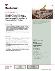
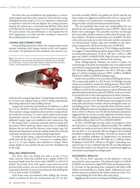
Fig. 1. The 13⅜-in. x 17½-in. OD <strong>casing</strong> bit used offshore australia<br />
is designed for unconfined compressive strengths up to 15,000<br />
psi (1,034 bar). The bit’s five steel blades, fitted <strong>with</strong> 19-mm PDC<br />
cutters, are displaced at TD prior to cementing.<br />
sidered in the <strong>casing</strong> design phase. Casing design must also factor<br />
in burst and collapse loads as well as sealing requirements<br />
after being subjected to these drilling stresses.<br />
Casing and connection specifications for Barberry-1 called<br />
for 13⅜-in., 68 lb/ft, L-80 pipe <strong>with</strong> API buttress connections.<br />
This common <strong>casing</strong> connection does not have a torque shoulder<br />
inside the connector ("J" area), which results in low-torque<br />
transmission capacity. To provide additional torque resistance,<br />
dedicated torque rings were installed in each connection, Fig.<br />
3. The torque ring is a pressure-actuated, metal-to-metal sealing<br />
system. When made up, initial contact force is established<br />
between the pin end and the fulcrum center torque ring. Additional<br />
internal pressure increases sealing contact force beyond<br />
axial loads and pressure of accepted string design limits.<br />
To make up the <strong>casing</strong>, a special insertion tool was used to<br />
install and seat the ring in the "J" area prior to coupling. Makeup<br />
at 5 to 14 rpm requires close attention to torque. When<br />
torque begins to rise quickly, the pin nose has shouldered up<br />
to the rings.<br />
DRILLING OPERATIONS<br />
The 20-in. shoe was drilled out <strong>with</strong> a re-run 17½-in.<br />
roller cone bit, which then drilled on to a depth of 685.73 ft<br />
measured depth from the rotary table (MDRT) or 367.47 ft<br />
drilled. Two of the 36-in. <strong>hole</strong> opener cones were lost in the<br />
previous <strong>hole</strong> section; one was retrieved but the second cone<br />
remained in the <strong>hole</strong>. It was not encountered while drilling the<br />
17½-in. <strong>hole</strong> to 685.73 ft MDRT.<br />
Total losses were encountered while drilling the section,<br />
which is common for the area. At that point, the 17½-in. bot-<br />
58 january 2012 / WorldOil.com<br />
tom-<strong>hole</strong> assembly (BHA) was pulled out of <strong>hole</strong> and the <strong>top</strong><br />
drive system was rigged up to drill-in <strong>with</strong> 13⅜-in. <strong>casing</strong>. A job<br />
safety analysis was conducted to communicate the DwC running<br />
procedure and all associated potential hazards.<br />
The pre-assembled shoe joint and <strong>casing</strong>-drilling bit was<br />
picked up and visually inspected to ensure all PDC cutters and<br />
blades were undamaged. The assembly was then run through<br />
the rotary table and flow tested to confirm that all nozzles were<br />
free of debris. The flush mounted slips were installed. The float<br />
collar joint was made up on the shoe joint and the connection<br />
was thread-locked. Torque rings were installed on the subsequent<br />
<strong>casing</strong> joints, which were made up to 25,000 ft-lb.<br />
The string was washed down to TD at 250 gpm until bottom<br />
was tagged. Casing drilling operations began at 685.73 ft <strong>with</strong>in<br />
recommended parameters of 60 to 100 rpm, 1,200 to 1,400<br />
gpm and 1,000 to 25,000 lb WOB. High-viscosity sweeps were<br />
pumped every joint to deliver effective <strong>hole</strong> cleaning.<br />
Some drilling-induced vibration was noted at surface. To<br />
avoid damage to the flush-mounted slips, they were replaced <strong>with</strong><br />
conventional <strong>casing</strong> hand slips. <strong>Drilling</strong> continued to the section<br />
TD. Maximum drilling parameters were 80 to 100 rpm, 1,400<br />
gpm at 1,350 psi standpipe pressure (SPP), 15,000 to 28,000 lb<br />
WOB and 15,000 to 22,000 ft-lb drilling torque.<br />
Some minor problems were encountered drilling the section.<br />
The <strong>casing</strong> string stalled at 1,426 ft and a 25-bbl high viscosity<br />
sweep was pumped to resume the drilling process. When ROP<br />
dropped to around 98.43 to 164.05 ft/hr and SPP increased to<br />
1,800 psi at 2,562 ft, the <strong>casing</strong> string was raised off bottom and<br />
partially hydrolyzed polyacrylamide (PHPA) mud was circulated<br />
around the bit to clear what appeared to be sticky claystone.<br />
<strong>Drilling</strong> resumed <strong>with</strong> the torque limit increased to 16,000<br />
ft-lb. High-viscosity, 25-to-30-bbl sweeps were pumped at every<br />
joint, <strong>with</strong> mud returns to surface observed during the entire <strong>casing</strong><br />
drilling process. This is not typically observed when conventionally<br />
drilling this interval. Standpipe pressure dropped 250 psi<br />
from 1,350 to 1,100 psi at 3,215 ft. Reverse hydraulic calculations<br />
suggested that one or more nozzles might have lost their ceramic<br />
liners, thus slightly enlarging total flow area. However, the section<br />
was drilled <strong>with</strong>out effect to TD at 3,296.09 ft MDRT.<br />
At TD, a 150-bbl high-viscosity sweep was pumped to clean<br />
the <strong>hole</strong> prior to running the wellhead assembly. The wellhead<br />
assembly was made up and run in <strong>hole</strong> on a landing string using<br />
the <strong>top</strong> drive. A 3-in. phenolic ball was dropped and circulated<br />
down<strong>hole</strong> to displace the bit blades. The ball was chased at 400<br />
gpm. An excellent indication of displacement was presented<br />
when the ball landed and the SPP built up to 1,600 psi before<br />
dropping to about 90 to 100 psi at 100 gpm. Cementing commenced<br />
once it was confirmed that the bit was fully displaced.<br />
The <strong>top</strong> drive system was retracted, the cement head rigged up,<br />
and cement was pumped according to plan.<br />
SUCCESSFUL RESULTS<br />
The 13⅜-in. DwC operation on the Barberry-1 well was<br />
successful by many measures. The planned depth of 3,296.09<br />
ft MDRT was reached at a high ROP, which saved approximately<br />
24 hours of rig operating <strong>time</strong> compared <strong>with</strong> offset wells<br />
drilled conventionally to a similar depth. Additional non-productive<br />
<strong>time</strong> was avoided by the onshore make-up of the 13⅜in.<br />
<strong>casing</strong>-drilling bit to the float collar and <strong>casing</strong>.<br />
Rigging up the <strong>top</strong> drive running and drilling system was ac-