The Use of AASHTO LRFD Bridge Design Specifications with Culverts
The Use of AASHTO LRFD Bridge Design Specifications with Culverts
The Use of AASHTO LRFD Bridge Design Specifications with Culverts

Create successful ePaper yourself
Turn your PDF publications into a flip-book with our unique Google optimized e-Paper software.
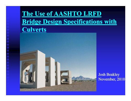
<strong>The</strong> <strong>Use</strong> <strong>of</strong> <strong>AASHTO</strong> <strong>LRFD</strong><br />
<strong>Bridge</strong> <strong>Design</strong> <strong>Specifications</strong> <strong>with</strong><br />
<strong>Culverts</strong><br />
Josh Beakley<br />
November, 2010
<strong>LRFD</strong> is Required<br />
June 28 th , 2000 FHWA Memo<br />
2
<strong>AASHTO</strong><br />
<strong>Design</strong><br />
<strong>Specifications</strong>
<strong>AASHTO</strong> Standard <strong>Specifications</strong><br />
for Highway <strong>Bridge</strong>s<br />
�� Section 3 – Loads<br />
�� �� Section 6 6 – <strong>Culverts</strong><br />
�� Section 8 – Reinforced Concrete<br />
�� S Section ti 12 12 – Soil-Corrugated S SSoil il C CCorrugated t d Metal M t l<br />
Structure Interaction Systems<br />
�� Section 16 – Soil Soil-Reinforced Reinforced Concrete<br />
Structure Interaction Systems<br />
�� Section 17 – Soil Soil-<strong>The</strong>rmoplastic <strong>The</strong>rmoplastic Pipe<br />
Interaction Systems
<strong>AASHTO</strong> <strong>LRFD</strong> <strong>Bridge</strong> <strong>Design</strong><br />
<strong>Specifications</strong><br />
�� Section 3 – Loads and Load Factors<br />
�� �� Section 4 4 – Structural Analysis Analysis and<br />
and<br />
Evaluation<br />
�� �� Section 5 5 – Concrete Concrete Structures<br />
�� Section 12 – Buried Structures and Tunnel<br />
Li Liners
Structures <strong>Design</strong>ed Per Section 12<br />
�� Section 12.7 - Metal Pipe, Pipe Arch, and<br />
Arch Structures<br />
�� Section 12.8 - Long Long-Span Span Structural Plate<br />
Structures<br />
�� Section 12.9 - Structural Plate Box<br />
Structures<br />
�� Section 12.12 – <strong>The</strong>rmoplastic Pipes<br />
�� Section 12.13 – Steel Tunnel Liner Plate
Concrete Structures <strong>Design</strong>ed Per<br />
Section 12<br />
�� Section 12.10 – Reinforced Concrete Pipe<br />
�� �� Section 12.11 12.11 - Precast Precast Box Box <strong>Culverts</strong>, <strong>Culverts</strong>, Cast<br />
Castin<br />
in-place place Box <strong>Culverts</strong>, Cast Cast-in in-place place Arches<br />
�� �� Section 12.14 12 14 - Precast Precast Three Three-Sided Three Sided<br />
Structures
What We Will Discuss<br />
�� Loads<br />
�� �� Load Factors<br />
�� Load Modifiers<br />
�� C Capacity it Calculations<br />
C l l ti
Live Load
Live Load<br />
�� 3.6.1.2 <strong>Design</strong> Vehicular Live Load<br />
��3.6.1.2.1 ��3.6.1.2.1 3.6.1.2.1 General<br />
General<br />
��“Vehicular “Vehicular live loading on the roadways<br />
<strong>of</strong> bridges or incidental structures structures,<br />
designated HL HL-93, 93, shall consist <strong>of</strong> a<br />
combination <strong>of</strong>:<br />
��<strong>Design</strong> <strong>Design</strong> truck or design tandem, and<br />
��<strong>Design</strong> <strong>Design</strong> lane load
Live Load Spacing – HL-93<br />
4000 lb.<br />
6f 6 ft.<br />
16000 lb. 16000 lb.<br />
14 fft.<br />
12,500 lb. 12,500 lb.<br />
12,500 lb. 12,500 lb.<br />
(12,00 lb per STD)<br />
<strong>AASHTO</strong> <strong>AASHTO</strong><br />
HS 20 LOAD ALTERNATE LOAD
Applied Live loads – No Lane<br />
Load<br />
�� �� 36133<strong>Design</strong>LoadsforDecks 3.6.1.3.3 <strong>Design</strong> Loads for Decks, Deck<br />
Systems, and the Top Slabs <strong>of</strong> Box <strong>Culverts</strong><br />
�� Where the slab spans primarily in the<br />
longitudinal longitudinal direction:<br />
direction:<br />
�� For top slabs <strong>of</strong> box culverts <strong>of</strong> all spans and<br />
for all other cases, including slab slab-type type<br />
bridges where the span does not exceed 15.0 15 0<br />
ft, only the axle loads <strong>of</strong> the design truck or<br />
design tandem <strong>of</strong> Articles 3.6.1.2.2 and<br />
36123 3.6.1.2.3, respectively, respectively shall shallbeapplied be applied.
Applied Live loads – No Lane<br />
Load<br />
�� 36133D 3.6.1.3.3 <strong>Design</strong> i Loads L d for f Decks, D k Deck D k<br />
Systems, and the Top Slabs <strong>of</strong> Box<br />
<strong>Culverts</strong><br />
��Where Where the slab spans primarily in the<br />
transverse direction, only the axles <strong>of</strong><br />
the design truck <strong>of</strong> Article 3.6.1.2.2 or<br />
design tandem <strong>of</strong> Article 3.6.1.2.3<br />
shall be be applied applied to to the the deck deck slab slab or or the<br />
the<br />
top <strong>of</strong> box culverts.
Lane Load – 3.6.1.3<br />
�� �� <strong>LRFD</strong> – 2004 – Truck Truck and and Lane Lane Load<br />
Load<br />
��64 64 lbs across a 10 ft width<br />
��DLA ��DLA DLA not not applied<br />
�� <strong>LRFD</strong> – 2005 – Truck only<br />
�� St Standard d d Specification S ifi ti – 3711 3.7.1.1<br />
��Either Either truck or Lane Load<br />
��Truck Truck governs for shorter spans
Pipe <strong>Culverts</strong><br />
�� Lane Loads not applied to pipe<br />
�� For top slabs <strong>of</strong> box culverts <strong>of</strong> all spans and for all<br />
other cases, including slab slab-type type bridges where the span<br />
does not exceed 15.0 ft, only the axle loads <strong>of</strong> the<br />
design truck or or design design tandem <strong>of</strong> Articles 3.6.1.2.2 and<br />
and<br />
3.6.1.2.3, respectively, shall be applied.<br />
��History History
Tire Footprint<br />
�� <strong>LRFD</strong> – 3.6.1.2.6<br />
��w ��w w = 20 in.<br />
��l l = 10 in.<br />
�� St Standard d d Specification S ifi ti – 641 6.4.1<br />
��“Concentrated “Concentrated Load”
Box Under Shallow Fill<br />
Distribution Width
Distribution Width<br />
�� <strong>LRFD</strong> (4.6.2.10)<br />
��E ��E E = 96 + 1.44S (for axle)<br />
axle)<br />
��E E in inches and S in feet<br />
�� St Standard d d(32432) (3.24.3.2)<br />
��E E = 4 + 0.06S (for wheel)<br />
��E E in feet and S in feet
Distribution Steel
Live Load Distribution Parallel to<br />
Box Culvert Span under Shallow<br />
Fill
Live Load Distribution<br />
STD – Spread a = a + 1.75*H 1 75*H STD – Spread b = b + 1.75*H 1 75*H<br />
<strong>LRFD</strong> – Spread a = a + 1.15*H <strong>LRFD</strong> – Spread b = b +1.15*H
Pipe Under Shallow Fill
Live Load Area for Depths ≥ 2 ft.<br />
�� <strong>LRFD</strong> (3.6.1.2.6)<br />
= (20/12 + 1.15D E)(10/12 E)(10/12 )(10/12 + + 1.15D 1.15DE) E)<br />
��A ��A L = (20/12 + 1.15D<br />
��1.15 1.15 above should be replaced <strong>with</strong> 1.0<br />
if if select select granular granular backfill backfill is is not not used<br />
used<br />
�� Standard (6.4.1)<br />
��A L = (1.75D (1.75DE) 2
Live Load Spread
Dynamic Load Allowance<br />
�� <strong>LRFD</strong> – Dynamic Load Allowance (3.6.2.2)<br />
��DLA ��DLA DLA = 0.33(1.0 - 0.125D 0.125DE) E)<br />
�� Standard – Impact Factor (3.8.2.3)<br />
��IM IM = 0 0.3 3 – 0’ 0’-0” 0” 0” to t 1’ 1’-0” 1’ 0” INCL INCL.<br />
��IM IM = 0.2 – 1’ 1’-1” 1” to 2’-0” 2’ 0” INCL.<br />
��IM IM = 0.1 – 2’ 2’-1” 1” to 2’-11” 2’ 11” INCL.
Two Trucks Passing
Live Load Distribution through<br />
Pipe and Soil
Multiple Presence Factor<br />
<strong>Design</strong> Code<br />
Lanes <strong>AASHTO</strong> <strong>AASHTO</strong> CHBDC<br />
STD <strong>LRFD</strong><br />
1 1.0 1.2 1.0<br />
2 1.0 1.0 0.90<br />
3 0.90 0.85 0.80<br />
4 075 0.75 065 0.65 070 0.70
Box <strong>Culverts</strong> – Shallow Fill<br />
<strong>Design</strong> Using Single Lane
Soil Load<br />
Soil<br />
Pi Prism<br />
Frictional<br />
Forces<br />
Soil<br />
Pi Prism<br />
Nt Natural lG Groundd Nt Natural lG Groundd<br />
Frictional<br />
Forces
Soil Load<br />
= Fe�� sBcH ��Boxes Boxes – Section 12.11.2.2.1<br />
��Pipe Pipe – Section 12.10.2.1<br />
�� W E =
Soil-Structure Soil Structure Interaction Factor<br />
Boxes<br />
�� WE = Fe�� sBcH ��F e = 1 + 0.20(H/B 0.20(H/ ( c) c)<br />
��F e shall not exceed 1.15 for installations<br />
<strong>with</strong> compacted p fill along g the sides <strong>of</strong><br />
the box section, or 1.40 for installations<br />
<strong>with</strong> uncompacted fill
Soil-Structure Soil Structure Interaction Factor<br />
Pipe<br />
�� “Standard installations for both<br />
embankments and trenches shall be<br />
designed for positive projection,<br />
embankment loading g conditions where F e<br />
shall be taken as the vertical arching factor,<br />
VAF, specified specified p in Table 12.10.2.1 12.10.2.1-3 3 for<br />
each type <strong>of</strong> standard installation.”<br />
www.concrete-pipe.org
<strong>AASHTO</strong> <strong>LRFD</strong> 12 12.10.2.1<br />
10 2 1
Vertical Pressures and Reactions
Vertical Soil Load<br />
2<br />
1.6<br />
1.2<br />
VAFi 0.8<br />
0.4<br />
0<br />
1 2 3 4 5 6 7 8<br />
“Bedding and Fill Heights for Concrete Roadway Pipe<br />
And Box <strong>Culverts</strong>” – C. Yoo, F. Parker, and J. Kang,<br />
Auburn University, June 2005<br />
l i
Bottom Reaction to Vertical<br />
Loads
<strong>LRFD</strong> (C12.11.2.3)<br />
�� “While typical designs assume a uniform<br />
pressure p distribution across the bottom slab, ,<br />
a refined analysis that considers the actual<br />
soil stiffness under box sections will result<br />
in pressure distributions that reduce bottom<br />
slab shear and moment forces (McGrath ( et<br />
al. 2004.”
<strong>LRFD</strong> C12.11.2.3<br />
�� “Such an analysis requires knowledge <strong>of</strong> in-<br />
situ soil properties p p to select the appropriate pp p<br />
stiffness for the supporting soil. A refined<br />
analysis y taking g this into account may y be<br />
beneficial when analyzing existing<br />
culverts.”
Pipe Pressure Distribution
Lateral Live Load<br />
�� <strong>LRFD</strong> (3.11.6.2)<br />
��“<strong>The</strong> �� “<strong>The</strong> <strong>The</strong> horizontal pressure �� �� ph h in ksf, ksf, on on a<br />
a<br />
wall resulting from a point load may be<br />
taken taken as:” as:<br />
[ ]<br />
P 3ZX2 R(1 2�)<br />
�ph = P<br />
�R2 3ZX2 R3 R (1 - 2�)<br />
R + Z
BBoussinesq i Distribution<br />
Di t ib ti
Live Load Lateral Uniform Pressure<br />
�� <strong>LRFD</strong> – 3.11.6.4<br />
�� Δ p = K γ s h eq<br />
��H H < 5 ft – h eq = 4 ft<br />
��H ��H H < 10 ft – h eq = 3ft 3 ft<br />
��H H < 20 ft – h eq = 2 ft
Lateral Uniform Live Load
“In general, <strong>LRFD</strong> produces greater live load surcharge<br />
pressures than Standard for depths <strong>of</strong> fill <strong>of</strong> 5 ft or less and<br />
less pressure for greater depths depths. In addition addition, live load<br />
surcharge pressures from <strong>AASHTO</strong> M 259 and M 273 are<br />
much greater than those from <strong>LRFD</strong> for depths <strong>of</strong> fill from<br />
0 to 1 fft and d lless than h <strong>LRFD</strong> ffor greater fill heights. h i h In I<br />
spite <strong>of</strong> the significant differences in live load surcharge<br />
pressures, p their impact p on reinforcement areas is relatively y<br />
minor”<br />
“Comparison <strong>of</strong> <strong>AASHTO</strong> Standard and <strong>LRFD</strong><br />
Code Provisions for Buried Concrete Box<br />
C<strong>Culverts</strong>” l t ” – RR. Rund R d & T. T McGrath, M G th STP 1368, 1368<br />
2000, Concrete Pipe for the New Millenium
Lateral Earth Pressure
Lateral Earth Load - <strong>LRFD</strong><br />
�� 3.11.5.5 – Equivalent Fluid Method<br />
��Loose ��Loose Loose Sand Sand or Gravel = 55 pcf<br />
��Dense Dense Sand or Gravel = 45 pcf<br />
�� 31152 3.11.5.2 – At Rest R t Pressure P<br />
��k o = 11-sin<br />
sin��<br />
���� = 30°, 30 , k o = 0.5, press = 60 pcf
Other Loads<br />
�� Always Considered<br />
��Self ��Self Self Weight<br />
Weight<br />
��Internal Internal Fluid Load<br />
�� S Sometimes ti Considered C id d<br />
��Construction Construction Loads<br />
��External External Hydrostatic Loads<br />
��Internal ��Internal Internal Fluid Pressure
Load Factors
Load Factors<br />
Load Load Factor<br />
Standard <strong>LRFD</strong><br />
Minimum Maximum<br />
Dead 1.3 0.90 1.25<br />
Water 1.3 1.0 1.0<br />
EEarth h– VVertical i l 13 1.3 090 0.90 130 1.30<br />
Earth - Horizontal 1.3 0.90* 1.35<br />
Live 1.3 x 1.67 = 2.17 0.0 1.75**<br />
*Per 3.11.7, a 50% reduction in load may be used in lieu <strong>of</strong><br />
the minimum load factor. factor<br />
**A multiple presence factor is included in the total load.
<strong>LRFD</strong> <strong>Design</strong>
Phi Factors<br />
�� Strength Reduction Factors<br />
���� ���� f = 1.0<br />
���� v = 0.9<br />
��<strong>LRFD</strong> <strong>LRFD</strong> – 12.5.5-1 1255 12551 12.5.5<br />
��Standard Standard – 16.7.4.6
“Basis <strong>of</strong> <strong>LRFD</strong> Methodology”<br />
�� ��η i�� iQ i < ��R n<br />
�� i = a statistically based load factor<br />
�� = a statistically based resistance factor<br />
�Q i = force effect<br />
�R n = nominal resistance<br />
n<br />
�ηi = load modifier relating to ductility,<br />
redundancy, y, and operational p importance p
Load Modifier - <strong>Culverts</strong><br />
�� <strong>LRFD</strong> 12.5.4<br />
��“Load �� “Load Load modifiers shall shall be be applied applied to<br />
to<br />
buried structures and tunnel liners as<br />
specified in in Article Article 1.3, 1.3, except except that that the<br />
the<br />
load modifiers for construction loads<br />
shall be be taken taken as as 1.0<br />
1.0”
Load Modifiers<br />
�� <strong>LRFD</strong> C 1.3.2.1<br />
��“Ductility, �� “Ductility, Ductility, redundancy, redundancy, and and operational<br />
importance are significant aspects<br />
affecting the the margin margin <strong>of</strong> <strong>of</strong> safety safety <strong>of</strong> <strong>of</strong> bridges.<br />
bridges.”
Load Modifiers (<strong>LRFD</strong>)<br />
For <strong>Culverts</strong><br />
�� Standard = N/A<br />
�� �� <strong>LRFD</strong> <strong>LRFD</strong> (1.3.2)<br />
��Ductility Ductility = ηD = 1.0<br />
��Redundancy Rd Redundancy d = ηR = 105 1.05 or 10 1.0<br />
��Importance Importance = ηI = 1.0 or 1.05
Load Modifier <strong>Culverts</strong><br />
�� <strong>LRFD</strong> 1.3.3 – Ductility<br />
��“<strong>The</strong> �� “<strong>The</strong> <strong>The</strong> structural system system <strong>of</strong> <strong>of</strong> a a bridge bridge shall<br />
shall<br />
be proportioned and detailed to ensure the<br />
development <strong>of</strong> significant and and visible<br />
visible<br />
inelastic deformations at the strength and<br />
extreme event limit states before failure.” failure.
Load Modifier - <strong>Culverts</strong><br />
�� <strong>LRFD</strong> 12.5.4 - Redundancy<br />
��“For �� “For For strength limit states, states, buried<br />
buried<br />
structures shall be considered<br />
nonredundant (1.05) under earth fill and<br />
and<br />
redundant (1.0) under live load and<br />
dynamic dynamic load load allowance.” allowance.
Load Modifier - <strong>Culverts</strong><br />
�� <strong>LRFD</strong> 12.5.4 - Importance<br />
��“Operational �� “Operational Operational importance importance shall shall be<br />
be<br />
determined on the basis <strong>of</strong> continued<br />
function and/or and/or safety <strong>of</strong> <strong>of</strong> the roadway.” roadway.<br />
roadway.”
<strong>Design</strong> Capacity
<strong>Design</strong> for:<br />
�� Flexure<br />
��Steel Steel Reinforcement<br />
��Concrete Concrete Compression<br />
�� �� Crack Crack Control<br />
�� Shear<br />
�� Radial Tension (for pipe only)<br />
�� Fatigue (not required for box culverts or<br />
pipe per <strong>LRFD</strong>)
Box <strong>Culverts</strong> and Pipe<br />
�� Section 12.10 – Reinforced Concrete Pipe<br />
�� Section 12.10.4.2 – Direct <strong>Design</strong> – As = ?<br />
g s<br />
�� Section 12.10.4.3 – Indirect <strong>Design</strong> – Class = ?<br />
�� �� Section 12.11 12 11 - Precast Box Box <strong>Culverts</strong><br />
<strong>Culverts</strong>
Flexure<br />
Asi<br />
�<br />
�<br />
�<br />
� � 2<br />
� �<br />
g��f� d � Nu � g�g��f�d � Nu� 2��f� d � t � 2Mu �<br />
EEquation ti 12.10.4.2.4a-1 1210424 1 – FFor Di Direct tD<strong>Design</strong> i <strong>of</strong> fPi Pipe<br />
Section 5.7.2 – Assumptions for Strength and Extreme Event<br />
Limit States takes a broader view <strong>of</strong> flexural design<br />
ffy<br />
�<br />
�
Flexure (Minimum Steel)<br />
<strong>LRFD</strong> - 12.11.4.3.2: STD - 16.7.4.8<br />
�� As min = 0.002 b h<br />
��b ��b b = 12 inch unit width<br />
width<br />
��h h = thickness <strong>of</strong> member in inches<br />
�� <strong>LRFD</strong>(1211432)<br />
<strong>LRFD</strong> (12.11.4.3.2)<br />
�� Standard (16.7.4.8)
ACI 318 318-08 08
Flexure (maximum steel)<br />
�� Box culvert walls and slabs are designed as<br />
tension controlled members, , <strong>with</strong> a<br />
maximum steel area <strong>of</strong> 75% <strong>of</strong> the balanced<br />
condition (steel ( will always y y yield before<br />
concrete crushes)<br />
�� �� Compression controlled controlled design design is is allowed<br />
allowed<br />
<strong>with</strong> other concrete structures as long as a<br />
modified modified phi phi factor factor is is applied.<br />
applied.
Tension Controlled - Ductile
Crack Control (<strong>LRFD</strong> – 5.7.3.4)<br />
s<br />
700�� e<br />
�<br />
��s � f fs �<br />
2d � c<br />
�� <strong>LRFD</strong> Concerns itself <strong>with</strong> steel spacing<br />
�� �� Standard Specification Specification concerns concerns itself <strong>with</strong><br />
<strong>with</strong><br />
stress in the steel (maximum <strong>of</strong> 0.6 fy?)
Service Load Stress<br />
f s<br />
�<br />
Equation C12.11.3-1<br />
C12 11 3 1<br />
�<br />
�<br />
�<br />
M Ms � N Ns� d<br />
As� j�i�<br />
d<br />
h<br />
� �<br />
�<br />
2<br />
�<br />
�<br />
�
Factors affecting crack control
Exposure Conditions
SHEAR
Shear<br />
<strong>LRFD</strong> – 5.14.5.3: STD – 8.16.6.7<br />
Slabs under 2 feet or more <strong>of</strong> fill<br />
�<br />
V 0 0676� f'c 46 A s Vu� de Vc ��<br />
��<br />
0.0676 fc ��<br />
4.6� � �� b b� d de bde � M u<br />
�<br />
Need not be taken less than<br />
Vc � 0.0948 � f'c�<br />
b�<br />
d e<br />
Equivalent to � = 3<br />
�<br />
�<br />
�
Shear<br />
<strong>LRFD</strong> – 5833 5.8.3.3: STD – 816621 8.16.6.2.1<br />
Slabs <strong>with</strong> less than two feet <strong>of</strong> cover,<br />
and sidewalls<br />
V Vc ��<br />
00.0316 0316��� � f'c fc�<br />
b bv� d dv � is based on the dimensions <strong>of</strong> the element and the strain<br />
in the steel
Shear<br />
<strong>LRFD</strong> – 5833 5.8.3.3: STD – 816621 8.16.6.2.1<br />
Slabs <strong>with</strong> less than two feet <strong>of</strong> cover, and sidewalls<br />
F ti ith ll d th l th 16 i h<br />
For sections <strong>with</strong> an overall depth less than 16 inches,<br />
and no tension, � can be assumed equal to 2
Top Slab<br />
12X12 @20’
Side Wall<br />
12X12 @<br />
20’
Distribution Steel
Distribution Steel<br />
�� In bottom <strong>of</strong> top slab (<strong>LRFD</strong> 9.7.3.2)<br />
��Percentage ��Percentage Percentage <strong>of</strong> <strong>of</strong> main main positive positive moment<br />
moment<br />
reinforcement = 100/S 1/2<br />
��S ��S S = span in feet<br />
feet<br />
��Need Need not be more than 50 percent<br />
�� In top <strong>of</strong> top slab<br />
��As As6 = 0.002 x Ag Agg<br />
6
CONCRETE PIPE DESIGN
Concrete Pipe Indirect <strong>Design</strong> – 12.10.4.3<br />
D-Load Equation<br />
www.concrete-pipe.org
www.concrete-pipe.org
EEarth th LLoad d BBedding ddi FFactor t
Extra Safety Factor for Type 1<br />
Installations<br />
www.concrete-pipe.org
Live Load Bedding Factor
www.concrete-pipe.org<br />
Pipe Indirect <strong>Design</strong><br />
D-Load Equation
Class V Pipe (C76/M 170)
Concrete Pipe<br />
Special <strong>Design</strong>/Direct <strong>Design</strong> –<br />
12.10.4.2<br />
�� Flexure – 12.10.4.2.4.a & b<br />
�� �� Radial Tension Tension – 12.10.4.2.4c<br />
�� Crack Control – 12.10.4.2.4d<br />
�� Sh Shear – 12.10.4.2.5<br />
1210425 12.10.4.2.5
FLEXURE<br />
RADIAL TENSION<br />
CRACK CONTROL<br />
SHEAR
<strong>The</strong> End<br />
This presentation can be downloaded at: