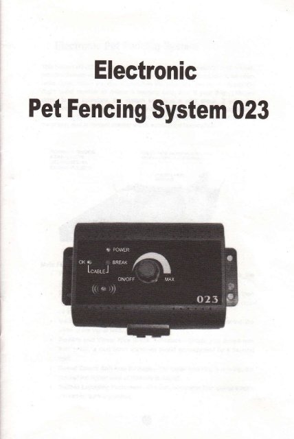
Electronic Pet Fencing System 023
Electronic Pet Fencing System 023
Electronic Pet Fencing System 023

Create successful ePaper yourself
Turn your PDF publications into a flip-book with our unique Google optimized e-Paper software.
<strong>Electronic</strong><br />
<strong>Pet</strong> <strong>Fencing</strong> <strong>System</strong> <strong>023</strong>
<strong>Electronic</strong> <strong>Pet</strong> <strong>Fencing</strong> <strong>System</strong><br />
This hidden HT-<strong>023</strong> fencing system is among the most reliable, cost€fficient<br />
pet containment systems available today. A buried wire transmits a harmless<br />
Gdio signal. When you dog approaches the boundary, the signal causes tte,<br />
dog's collar receiver to deliver a warning Oeep Rret. tt youidog onfinues<br />
closer to the boundary, the system will issue a mib sf,o"f. it you, Oog<br />
continues further, the system will issue stronger shocks until your dfo returnl<br />
to within the boundary your have set up_ your dog will naturjf seeito avoid<br />
correction, and is @ntent staying within established boundaries.<br />
Main Fealures:<br />
. Pulsed Proportional Stimulu-The closer your dog gets to the<br />
boundary, the more intense the shock will be;<br />
. Progressive Tone Stimulu-A waming tone will be issued firet, lhen<br />
o shock slimulus ofter4-l O seconds. lf yar dog continues to move closer<br />
to the boundory the shock stimulus will progressive.<br />
. Variable Field Width Controt-Allows you to precisely @ntrot the<br />
width ofthe signat field;<br />
. Audible and Visual Wire Break tndi€toE-_-Shoutd your buried wire<br />
ever break, a loud sonic alam will sound arcompanied by a flashing<br />
light;<br />
. Speed Detect Anti-Run through-The faster your dog is moving, the<br />
quicker the higher level of intensity is issued;<br />
. Built-in Lightning protection-protects transmitter frcm power surges<br />
@used by lightning strikes:<br />
o
. Muatiple Colhr Opmdor}-4dd as many @llars as you like to contain<br />
as many animls yd haw. Thffi is no limit to the number of @llaG it<br />
€n @ntrol.<br />
. Up to 5000 squaE metse E lg€ (@r 1 .2 are).<br />
Psckage ContenB:<br />
. 1 xlnd@rmll-mountedtsa|Mitts;<br />
. lxPilerplug;<br />
. 1 x Adjustable lBeiver cdlar:<br />
. I x 6 Vott battery for @lht<br />
. 1 x boundary wire of 300 rets6;<br />
. 2 x Exba metal @ntact pdnts;<br />
. 20 x TEining flag6;<br />
. lxTestbulb;<br />
. 4xsmre;<br />
. lxUse/smanual.<br />
Other items you may ns"d:<br />
. ScrewdriveE<br />
. Straight edged spade or a lawn edger;<br />
. Wire stipping plieE:<br />
. Electri€l tape;<br />
. Waterpmfing @mpound (e-9. sllicone eulk);<br />
. Patching @mpound for your type of driveway or sidewalk;<br />
. PVC pipe if crossing a gravel or dirt driveway, pond or lake;<br />
. Pencil, Ruler or Prcfactor;<br />
. Drillwith drill bit or ma$nry bil if drilling thmugh wood or @ncrete;<br />
. Additional Boundary WiE.<br />
CAUNON<br />
Please take a few minutes to read the instruclion man@l priq to your fiBt use.<br />
For best results, follN thes important ruls:<br />
. Th6 sl€clronic dog cdlar b inteoded qly for m m dogs.<br />
. A low battery may €us inE mitlent opeElim. DO NOT USE if you<br />
suspec{ a low batbry.<br />
. Allow your dog to get usd to th6 @ilar before you begin haining. you<br />
want your dog lo a@pt the @llar as part of a Eutine, not to a$ociate<br />
the @llarwith @rection.<br />
. DO NOT leave the collar on your dog for more than 12 h@G per day.<br />
. NEVER perfom set-up prc@dures when the @llar is on your dog.<br />
. An electrcnic @llar should only be 6ed under dos supervision by the<br />
dog's owner.<br />
r KEEPOUTOFTHE REACH OFCHTLDREN.<br />
. Read all instructions before using this prcduct.<br />
IMPORTANT<br />
Realize that bmuse individual dogs have unique tempemments, lhere is no<br />
way of knwing how your dog will react to its intoduclim lo this prcduct. For<br />
the safety of your dog, initial faining shoutd take pla@ using a long teash to<br />
keep you in @ntrol of the situation. Also Ealize that an aggcssive animal<br />
could tum against th€ handler upon reeiving the stimulus. Therefore, if you<br />
f€el you dog has an aggre$ive behaviqr and/or il has a hisbry of aggresive<br />
behaviour, you should @nsult a @rtified animal behaviourist bafore using this<br />
produc{.<br />
sEcTroN 1<br />
INSTRUCTIONS FOR SETTI}IG UP YOUR COI{TAINIf,ENT SYSTET<br />
STEP I<br />
PREPARE A LAYOUT OF YOUR CONTAINMENT AREA<br />
A. D6i9n and Dmw DiagEm<br />
PrepaE a diagram of the area you want io mntain your dog. A diagEm will<br />
help to avoid unforeseen obstacles. lnclude the lmtion of hous, drivmy,<br />
pond, gaden, swimming pool, etc. It your neighbou has a @ntainment system<br />
installed, ml* the l@tion of the buried wire on your diagEm.<br />
B. Contact tltlltly Company<br />
Contact your utility compani6 to mark any buried utility lin6s_ Be sure to<br />
include the buried lines on your drawing be@use lhe* utility lines will afecl<br />
the placement of you wire.<br />
C. Deiemine Loetion of Wall TEnsmitter<br />
The tansmitler €n be mounted to a wall near any standard 240_volt<br />
household outet with the included screre. lt will wiihstand frezing<br />
tempeEfures, but it is not waterproof. Thereiore, it is best to l@te the<br />
tEnsmitter in an enclosed area. lnstall the transmitter at least thE ieet (we<br />
onsider ten feet will be better) from any large metal obiects $cfi 6 breaker<br />
boxes, waler heatere, metal ga€ge d@8, or washer and/or dryer. Whea<br />
e o
installing the transmitter make sure the wire is not cut off or pinched by a<br />
window, door or garage door. When drilling holes, make sure there are no<br />
electrical wires, nails or screws inside the area you are drilling.<br />
D, Determine the Exit Route ofYour Boundary Wire from the Transmitter<br />
to the Outside Containment Area<br />
Since your tEnsmitter must be mounted in an enclosed area to protect it from<br />
the weather, give careful consideration on where the wire exits to the exterior.<br />
Existing openings such as a window, door or utility line hole may provide easy<br />
access to the outside. You may need to drill a hole through the exterior wall.<br />
STEP 2<br />
ADD PROPOSED WIRE LOCATION TO YOUR DMWNG<br />
l\,!ark your diagram with the proposed lo@tion of your wire. This will provide an<br />
easy referen@ as you install the wire. For the system to wo* propedy, the<br />
wire must make one continuous loop. The signal is transmitted from one<br />
terminal ofthe transmitter, through the wire and back to the other teminal.<br />
Example lnstallation Diagrams<br />
Keeps you. pet safely away from<br />
gardens, pools, and other areas.<br />
Basic Single Wire Zone<br />
You. pet has a 360 degree perimeter to .oam<br />
within.<br />
Dual Zones Open Back Zone<br />
Keep pets sepaEted, or to<br />
oll-".i""'lllil: _<br />
Single loop - Back Yard Zone<br />
Your pet has run of the house and<br />
back yard.<br />
Your pet has run ofthe house and<br />
back yard.<br />
o o<br />
This lets your pet have access to the lake or<br />
other rear area_<br />
Single Loop - Front Yard Zone<br />
Your pet has run olthe house and front yard<br />
Double Loop - Back Yard Zone Double Loop - Front Yard Zone<br />
Your pet has run of the house and front yard
Front & Rear BarrierZones Side Barier Zones<br />
Your pet has full access to both Your pet has full affis to the frcnt or rear, bul<br />
sides, but not to the ftont or rear. nol to lhe sides.<br />
IMPORTANT NOTES FOR wlRE PLACE]IIENT:<br />
. Do NOT run the wire less than 15 metres undsr any oc6iona. Do<br />
NOT tum the field width knob to milimum whsn the wire is iust<br />
over 15 metrea, otheruise it will bum th6 wall transmitter (lr3 of<br />
6eld widih knob iurn is maximum). Wrc MUST be over 100 metrea<br />
if you need to tum iho field width knob to milimum. lf rcquircd<br />
wire is shorter than l0O metres, it will be safer to run double or<br />
ev6n triple loop to make the layout wire over 100 metrss.<br />
o Do NOT run the l@p within 2 mete6 parallel lo elechi€I, telephone,<br />
Gble TV, or other buried wire in the yard.<br />
. Do NOT run one section of wire within 3 mete6 of another section or<br />
the signal may en@|.<br />
. Do NOT run your wire within 3 meteE of any adja@nt @ntainment<br />
system's wire.<br />
r Do NOT run your wiB witiin 3 @nti-meteE of any steels baE under<br />
conrete grcund otheruise signal strength will be redued.<br />
STEP 3<br />
ESTIMATE THE AMOUNT OF WRE NEEDED<br />
HT{23 model includes 300 metres of boundary wire. lt €n enclose an area of<br />
over 1.2 acres.<br />
The amount of wire needed is detemined by several facto6:<br />
(a)Total area to be contained:<br />
(b)Using a double loop. This reouires twice as much wire_<br />
o<br />
(c)Size of the signal ,ield. The signal field is the distance from the wire to the<br />
pla@ where the mllar receiver firsl activates. A 3 to 4 metec wide feld is<br />
prefered.<br />
STEP 4<br />
INSTALL THE WALL TMNSMITTER<br />
lnstall the wall lransmitter close to a standard 240-volt household ouflet. Do<br />
not plug the tEnsmitter to the outlet until the boundary wire is in pla@.<br />
IMPORTANT NOTE: We re@mmend that you unptug the transmitter and<br />
disconnect the fene wire during lightning stoms.<br />
If builde {ife &d,a 1o!d<br />
s@i@lam nll so@d<br />
STEP 5<br />
LAY OUT THE PERITETER wlRE<br />
IMPORTANT NOTE: Do NOT bury the wire untit you have tested the system<br />
and are sure it is working properly. Do NOT nick or scmpe the wire during<br />
installation. lmproper fu nction may result.<br />
1. Use your drawing as a refe€n@. Begin laying the wire aDund the perimeter<br />
of your @ntainment area to form a @ntinuous loop. Use gEdual turns at the<br />
@meE with a minimum of lmeter radius. This provides a more @nsistent<br />
signal Iield.<br />
2. lf you are using more wiE than initially supplied with your @ntainment<br />
system, the wire connections must be waterproof to provide a sealed<br />
connection between the wires. Do not use electri@l tape or twisted wire nuts.<br />
This will @use an intermittent signal or disam the system.<br />
3. Continue around your perimeter until you return to the start ofthe loop.<br />
4. Cut the wire.<br />
o
STEP 6<br />
CONNECT THE PERIMETER WRE TO THE WALL TRANSMITTER<br />
The wire from the perimeler to the wall transmitter should be twisted lo €n@t<br />
the signal. This allows the dog to cros the area without rmiving a @rection.<br />
It also elimlnates posible interferene from elechi€l wires, etc.<br />
1. Measurc the distane from the wall tmnsmitter to th€ edge of the perimeter<br />
wire.<br />
2. Beeue twisting the wire demass the length of the wie, multiply the<br />
dislan@ by 1Y2.<br />
3. MeasuE and @t two wires of equal lengths of the above nieasurement.<br />
4. Hold the two ends of the wiB side by side and twist thm together. The<br />
wiEs en be twisted manuaily until the twists are 6 to i2 cm apart. The tighter<br />
the wire is twisled the better the signal @n@llation.<br />
5. Pull the twisted wic to the perimeter loetion of the two ends of your<br />
boundary wire loop. Spli@ lhe ends of the lwisted wire to the ends of the<br />
boundary wire ONLY with waterproof splies.<br />
6. Put the twisted wiEs through the existing opening or ddlled hole so it €n be<br />
@nnected to the transmitter.<br />
7. Strip off about 1 cm of insulation ftom $e end of each twisled wire_<br />
8. lnsert the wires into the teminals ol the transmitter.<br />
9. Plug the power adapter into a standard 240-yolt household ouflet.<br />
'10. Connect the power adapter to the transmitte/s power port.<br />
STEP 7<br />
VERIFY TRANSMITTER IS FUNCTIONING PROPERLY<br />
To veriry the transmitter is functioning prcpedy, look for OK and power lights<br />
on the tEnsmitter. When both of them tum green, it means the tEnsmitter is<br />
receiving power, both wires are @nnected, and the wire forms an unbmken,<br />
@ntinuous l@p. lf the Break light tums red, it means that one or both wires arc<br />
rct prcperly onnected or both wires are mnnec{ed but the wire is broken.<br />
Corect the prcblem and retest.<br />
STEP 8<br />
SET UP YOUR COLLAR RECETVER<br />
lnserl 6V 41R44 battery in the @ltar re@iver following the positive (+) and<br />
negative G) signs inside the battery @mparfnent. tn@rect instailation @uld<br />
euse permanent damages to some elect onic parts. When the indi€tor light<br />
tums green, it mmns the @llar reeiver is working properly. When the indicaior<br />
light lums red, it means battery is running dom and needs to be eplaged.<br />
o<br />
,.,.","f,Pffi.*,<br />
IMPORTANT NOTE: Do NOT ptace the @llar €eiver on your dog unijt the<br />
@ntainment system has been tested and the signal fietd adjusted.<br />
STEP 9<br />
TEST THE GONTAINMENT SYSTE]II<br />
DO NOT TEST THE CONTAINMENT SYSTEM WITH THE COLLAR<br />
RECEIVER ON THE DOG. You must manually test the @ntainment system to<br />
verify lhat the signal is propedy transmitt€d though the wiE. U* the supplied<br />
lest light.<br />
Select a section of slEight boundary wirc that is at least 50 feet long. Attach<br />
the supplied test light to the receiver prcbes and hold the ollar re@iver at your<br />
dog's neck height. Slowly walk the @llar toward the boundary wire. Listen ior<br />
lhe waming tone and watch for the test light to light. The wider you @n make<br />
the @ntainment field, the less chance your dog en run thrcugh. Adjust the<br />
FIELD WDTH as nee$ary and test again.<br />
Test in a number of difierent areas until you are stislied there are no wiE<br />
breaks and the system is functioning prcperly.<br />
Next walk all around the "safe" part of the yard to ensure ihere are no stray<br />
signals, particularly near the twisted wlre 6ming frcm the trarsmitter. Tesl<br />
@llar in and around the inside of the house as well. Signals fmm Cable TV,<br />
eloctiel or telephone lines en "couple,' Busing stmy sjgnals inside and<br />
outside th€ house that €n ac{ivate the dogt @llar accidentally. lf you do<br />
encounter tiis phenomenon, your boundary wire is probably too dm to thes<br />
outside lines and will need to be moved or modified. Containment @llaE<br />
should not be worn inside the house.<br />
STEP 10<br />
ADJUST THE SIGNAL FIELD WDTH<br />
The signal field is the disian@ from the wire to the plac where th6 6llar<br />
re@iver fi6t aclivates. The Fietd Width Knob adiusts the size of the sigml fietd,<br />
o
not the @rection intensity. Tuming the knob clmkwise increases lhe signal<br />
field width; tuming it munter-delsis dereases it. Tuming the knob<br />
@mpletely @unter-dockwise switches off the lransmitter power.<br />
Fdlry the instructions in SteQ 10 to test the siqnal fietd width. Walk the entire<br />
Qerimeter to be suc that the signat fied is @nsisteat thrcuqhout ys(<br />
$fik{afi€*.rs.\\ss$r*,5fi*.*r$r*eEtffi*Enffi]]w 6}tTiem m<br />
either side of the wire (creating a 4 meter wide field). A 3 to 4 meter wide field<br />
is prefered. The wider the signal feld width, the les chan@ that a dog @n<br />
run through he field.<br />
IMPORTANT I{OTE: lf the Field Width knob is Emoved or the position of the<br />
knob is altered by tuming it clockwise or @unter-clockwise, you must always<br />
check the signal field for the desir€d setting. Refer to Step 10, test the<br />
Containment <strong>System</strong>-<br />
STEP,II<br />
INSTALL THE BOUNDARY WRE<br />
Tools Needed - StEight€dged spade, wire cutter / stipper, and standard<br />
screwdriver. tf you plan to run the wire acrcss onsete, you will also need a<br />
mulk gun, sili@ne eulking, and a cirular saw with a masonry blade.<br />
Burying the wlrc - The wirc d@s not have to be buded, but for potection you<br />
prcbably want to bury it at least one inch undergrcund. Start by digging about 7<br />
to 10 m dep where the wire fiBt enteE the grcund near the Aansminer and<br />
@ntinue arcund the path of the l@p wire.<br />
Note: When @vering a large ar6a, you may wish to use a trenching machine<br />
to cut into the grcund. Hwever, we mmmend that the wire be placed in the<br />
trench by hand. A ommercialwiBplacing machine may break the wire.<br />
Driveways / Sidewalks - When mssing an asphalt driveway, make a 2 cm<br />
de6p @t across the driveway using a circular saw and masonry blade. place<br />
the wire in the cEck and seal wilh asphalt sealant. On driveways and<br />
sidewalks, if an expansion ioint is available, simply place the wire in the joint<br />
and seal with an outd@r €ulk. When crcsing gEvel, bury the wire at least 7<br />
cm deep U$ an old garden hose or plastic PVC piping to protect the wire. ln<br />
water, andpr the wire with large rccks- Protect the wire with an old garden<br />
hose or plas$c PVC piping.<br />
STEP 12<br />
INSTALL THE BOUNDARY TRAINING FLAGS<br />
After installing the wire, retest lhe ontainment system as describ€d in Step 10,<br />
Test the Containment Syst6m. Vedry that the signal field width is @nsistent by<br />
following the instructions in Step 'l 1. Adjust the Signal Field Wdth. As you are<br />
@<br />
relesting and verirying the system, install the boundary training flags. Pla@ the<br />
flags where the waming tone is fiEt heard as you apprcach the wire. The fags<br />
should be pla@d at the edge of the signal field width, not directy on the wire.<br />
This will add a visual oe lo the audio waming tone and help leur dog to leam<br />
(\e \a\RdNl-<br />
STEP 13<br />
FITTING THE COLLAR TO YOUR DOG<br />
IMPORTAT{T ltoTe Never leave the @,,ar Eeiver on the dog for longer than<br />
12 houre a day. Leaving the @llar on the dog for extended periods @uld Hult<br />
in skin iritation. Check your dog's neck periodi@lly for skin iritalion.<br />
A. Prcbes<br />
. Make suE both prcbes @ntact the dog's skin. lf neded, a small<br />
amount of hair removal or thinning will improve prcbe @ntact with the<br />
skin.<br />
. Use shorl prcbes for short-haired dogs. Use long probes for long-haired<br />
dogs.<br />
. Finger-tighten the prcbes, then tum them one additional Evolution. Do<br />
not over{ighten.<br />
. Check the tightne$ of lhe prcbes regularly to pEvent toss of the<br />
receiver box.<br />
B. Collar Stmp<br />
. To pBvent a@idental @trec.tion inside the home, Emove the @llar<br />
faom the dog's neck when it @mes inside.<br />
. Pla@ the collar arcund the dog's neck with the receiver box under lhe<br />
chin. The @llar must be on relatvely tight to keep the probes making<br />
skin @ntact without restricting breathing. You should be able to slide<br />
only one finger underthe stap at the back ofthe dog's neck.<br />
. Always make sure the @llar is functioning prcperly BEFORE putting it<br />
on the dog.<br />
. R€move other metal @lla6 when the dog wea6 the @ntainmenl collar.<br />
Metal collars may interfere wilh pDper opeEtion.<br />
. Remove lhe collar and tdm the excess stmp.<br />
sEcTtolr 2<br />
HOWTHE CORRECTION WORKS<br />
'1. Prc-Coretion Waming Tone: When the dog reaches the edge of the<br />
signal field in the yard, it will hear a waming tone that lasts aboutfour to ten<br />
smnds.<br />
o
lf the dog does not rctum to the safe pan of the yard, it will l@ive a<br />
@ntinuous @rection and slight sh@k until it retums to the sfe area.<br />
2. Run-Thrcugh Prevonlion: The re@iver aulomati€lly inqeases the<br />
@nection s the dog enteB the signalfield. The dog ennot'run thrcugh. the<br />
signal field without re@iving a strong orrection.<br />
sEcTtoN 3<br />
TRAINING YOUR DOG<br />
To get the mct out of your containment system when tBining, keep those tips<br />
in mind:<br />
. To prevent accidental @rec{ion inside the home, remove the @llar<br />
from the dog's n$k when it @ms inside.<br />
. Always make sure the 6llar is functioning properly BEFORE putting it<br />
on the dog. Verify the system is operating prcperly and the field width is<br />
appDpriate as described in Sectjon .1, Step 11. Adiust the Signal Field<br />
width.<br />
. Stay positive and playtul during the t€ining session.<br />
. Keep training sessions brief. Never onlinue a session after your dog<br />
has lost interesl. Take a break to rest or play.<br />
. ALWAYS pEise your dog for good behaviour.<br />
The ,ollowing steps outline a su@ssful tEining plan:<br />
STEP I<br />
FLAG TRAINING<br />
'1. Tum the mll transmitter "otr so no @rections will be given to your dog.<br />
2. Plae the @llar reeiver on your dog.<br />
3- Pla@ a long lmsh on lour dog. play with you dog in the safe area of<br />
the yard for 2-4 minutes. Do not allow your dog to run free or crcss the<br />
flag lines.<br />
4. Walk towards the flags. Reach down and shake a flag. Say'bad flag, in<br />
a disapprcving tone.<br />
5. Retum to tie @ntre part of the yard and play with your dog. Reward<br />
with treats.<br />
6. Repeat this exercise several times in various lo€tions of the yard.<br />
STEP 2<br />
THE FIRST CORRECTION<br />
o<br />
'1. You need lo reset the signaltield width before placing the @llar reeiver<br />
on your dog. FdlM the instructions ouilined in Section 1, Step 11,<br />
Adjust the Signal Field Width.<br />
2. Pla@ the @llar rmiver on you dog in the safe area of the yard.<br />
3. Pla@ a long leash on your dog. Ptay with the dog in the sfe area of the<br />
yard.<br />
4. Wdk towards the ltags. lf your dog tries to avoid the flags, prais and<br />
ca$ure yourdog.<br />
5. Repeat this step in other lo@tions of th€ yard.<br />
6. Allow no more than thre corections in a day or seven in a reek. This<br />
deponds on your dog's slress toleEne. Most dogs only re@ive a few<br />
@redions during the haining phase; they respond to tone very quickly.<br />
7. Reward your dog when it avoids the flags, even if a @rection is i$ued.<br />
8. Play in the safe zone with your dog before ending this training sesion.<br />
STEP 3<br />
ON-LEASH PROOFING<br />
'1. With the 6llar on you dog and lhe wall transmitter "on", play with your<br />
dog (on leash) in the safe aea. After a few minutes of play, to$ a toy or<br />
treat through the llags.<br />
2. lf your dog runs through the ftags to chase the toy, wait for the starUed<br />
respons and pullyour dog back into the safe area. praise and ward<br />
Your dog.<br />
3. Reinfo@ training by shaking a flag. Say'bad flag'with a dispproving<br />
tone. Consider inreasing the signal field area. lf you ch@se to<br />
increas the signal feld area, remove the @llar fom your dog, increa*<br />
the signal field, and retest. Referto Section 1, Step 11, Adjustthe<br />
Signal Field.<br />
4. Repoal this exercise in other lMtions of the yard.<br />
5. Pmise your dog when it avoids the flags. Stay positive and playtul<br />
during the training session.<br />
6. When your dog refuses to run thrcugh the flags 20 @nsecutive times,<br />
prceed to the next step.<br />
STEP 4<br />
OFF.LEASH PROOFING<br />
1. Follow the instructions in St€p 3, On-Leash Prcofing exept drcp the<br />
leash on the grcund. ll will be available if you need to retrieve your dog.<br />
2. lf your dog gets thrcugh the signal field during this phas, quickty<br />
r€move the @llar. Bring your dog back inlo the sfe aEa. put the @llar<br />
back on your dog. Reinfor@ 'bad flag' tEining. PEisB and reward your<br />
dog.<br />
3. Repeat this off-leash training until you are @nfident that your dog wilt<br />
ignore temptations outside the @ntainment area.<br />
o
sEcTtoN 4<br />
SYSTEM MAIilTENANCE TIPS<br />
Your system requires very little maintenan@. The battery{Fiemted 6llar<br />
reeiver is water Bsistant and should not be immeFed in any liquid. This will<br />
muse damage not @vered under the manufaclurer's waranty.<br />
Th€ wall transmitter is not waterpr@f and must be prctected fom the weather.<br />
A close lightning shike may damage the unit. Unplug the tEnsmitter and<br />
dis@nned the wires during stom.<br />
Do not aftempt to dismantle or repair any oflhe system @mponents; this will<br />
void the manufacture/s wamnty.<br />
Test the system on@ a week io make sure lhe @llar re@iver is working<br />
properly. Also, testing the system will vedfy the field width setting is @rect. To<br />
test, attiach the supplied test light to the @llar reiver pmbes. Holding the<br />
re@iver by the case, NOT by the prcbes, walk into the signal feld. Listen for<br />
the waming tone to sound and the test light to illuminate.<br />
sEcnoN 5.<br />
TROUBLESHOOTING GUIDELINES<br />
A. Dog is not responding to corec'tion:<br />
. Adjust the collar fit.<br />
. Tim the dog's hair or use l@ger prcbes to make better skin @ntact.<br />
. Change lhe baitery in the @llar re@iver.<br />
B. <strong>System</strong> Test Preedurc:<br />
Whenever you expedene a malfunction, you will need to do a Tsst L@p to<br />
detemine which componenl - @llar, wall transmitter, or yard wire - is not<br />
working. To perfom the Tst L@p proedue:<br />
't.<br />
3.<br />
4.<br />
5.<br />
6.<br />
7<br />
Make a lest l@p using a pi@ of wiE at least 4 metec in length.<br />
Remove the existing wire from your wall traremitter.<br />
lnsrt the two ends of the lest loop wire into the wall tBnsmitter.<br />
Tum the field width knob to a lw setting.<br />
Pla@ the test light on the @llar recdiver. With the @llar in hand, move<br />
outside the field and appoach the test loop. Make a mental note of the<br />
distane between the collar and the wire when the @llar activates.<br />
Tum the feld width knob to a medium setting.<br />
Back away frcm the wire and appr@ch it again. Determine the distan@<br />
betwren the @llar and the wire when the @llar activates. The distanG<br />
should be greater on the medium range setting.<br />
8. lf more than one @llar receiver is used with the system, repeat the<br />
above test on each collar.<br />
Results of <strong>System</strong> Test Pmedures:<br />
lf there is no gEen POWER light on the wall transmitter with the test loop wire<br />
in place, the wall transmitter is malfunctioning.<br />
As this unit has a proteclion tunction, if ffie matteE or operate faull @us<br />
the system halted (no green POWER light), pl€se unplug the pfler of tie<br />
tmnsmitter. afrer ten minutes plug the pow6r again, it will re@ver to nomal<br />
woIk.<br />
lf the g@n POWER and OK lights are solid on the wall kansmitter, but the<br />
collar does not activate on the test loop wire, the @llar rreiver is not working.<br />
Change the battery in lhe collar rreiver and repeat the test.<br />
lf the red Break light on the transmitter tums on together with beeping sound,<br />
the problem is in the yard wire.<br />
@ o
Warning:<br />
l.Tte rytu iacluded a boudary wire of 300 meG. Ifthw stil have ey wffi aftq you<br />
used it to @kc fre fm@ wire. Pleee mt dom the I@t wirc. you @'t w the lmemt<br />
wire 6md withthe tuih.Othwie the tumihwil @,t worting EWly<br />
(fhis corn@t wry is wng)<br />
2.If thft e ey womg orution caus€d tbe rytu wo.king uconventioaally.plw<br />
unplug the pwd of th€ tuiffi.AftEr 5 min&s,The sysh wil wort pryedy when you plw<br />
tle pwa ag.in.<br />
(f[ii comet ssy is right)<br />
@