View - IMM - RWTH Aachen University
View - IMM - RWTH Aachen University
View - IMM - RWTH Aachen University

You also want an ePaper? Increase the reach of your titles
YUMPU automatically turns print PDFs into web optimized ePapers that Google loves.
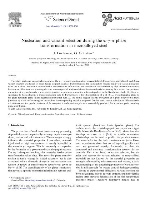
Abstract<br />
Nucleation and variant selection during the a–c–a phase<br />
transformation in microalloyed steel<br />
I. Lischewski, G. Gottstein ⇑<br />
Institute of Physical Metallurgy and Metal Physics, <strong>RWTH</strong> <strong>Aachen</strong> <strong>University</strong>, 52056 <strong>Aachen</strong>, Germany<br />
Received 19 August 2010; received in revised form 8 November 2010; accepted 8 November 2010<br />
Available online 4 December 2010<br />
This study addresses variant selection during the a–c–a phase transformation in recrystallized, low-carbon, microalloyed steel. Since<br />
variant selection was found to occur during incipient stages of transformation, the investigation focused mainly on c-grain nucleation<br />
from the a phase. To obtain comprehensive microstructure information, the sample was characterized by high-temperature electron<br />
backscatter diffraction in a scanning electron microscope and additional three-dimensional serial sectioning. It is shown that preferred<br />
nucleation at a grain boundary near a triple junction requires an orientation relationship close to the Kurdjumov–Sachs (K–S) correspondence<br />
to both adjacent a grains (nucleation rule I). Furthermore, a low disorientation of a {1 1 0} bcc crystallographic plane to<br />
the grain boundary plane favors nucleation (nucleation rule II). The results suggest that the nucleation of c grains is favored at triple<br />
junctions by a low surface energy of the nucleus. A corresponding model is proposed. On this basis, variant selection of different ferrite<br />
orientations and the product textures of the complete transformation cycle were successfully predicted for a random grain boundary<br />
plane distribution.<br />
Ó 2010 Acta Materialia Inc. Published by Elsevier Ltd. All rights reserved.<br />
Keywords: Microalloyed steel; Phase transformation; Crystallographic texture; Variant selection<br />
1. Introduction<br />
Available online at www.sciencedirect.com<br />
Acta Materialia 59 (2011) 1530–1541<br />
The production of steel sheet involves many processing<br />
steps which are accompanied by a change in phase composition,<br />
texture and microstructure. These changes strongly<br />
influence the material properties. Low-carbon, microalloyed<br />
steel at high temperatures is usually hot-rolled in<br />
the austenite (c) regime. This is commonly accompanied<br />
by the formation of a pronounced crystallographic texture.<br />
During subsequent cooling, the austenite–ferrite phase<br />
transformation takes place. This reversible phase transformation<br />
causes a change in crystal structure, but is also<br />
associated with a dramatic change in microstructure and<br />
texture. A review of transformation textures was given by<br />
Ray et al. [1]. The crystallography of the phase transformation<br />
reveals a specific orientation relationship between aus-<br />
⇑ Corresponding author.<br />
E-mail address: Gottstein@imm.rwth-aachen.de (G. Gottstein).<br />
1359-6454/$36.00 Ó 2010 Acta Materialia Inc. Published by Elsevier Ltd. All rights reserved.<br />
doi:10.1016/j.actamat.2010.11.017<br />
www.elsevier.com/locate/actamat<br />
tenite (parent phase) and ferrite (product phase). For<br />
carbon steels, this crystallographic correspondence typically<br />
follows the Kurdjumov–Sachs (K–S) orientation relationship,<br />
or close to it [2–5]. A specific orientation<br />
relationship can be used to predict the product texture.<br />
The same holds for the back transformation (a–c). However,<br />
experiments show that not all crystallographic variants<br />
are generated equally frequently, so that the<br />
computed and measured transformation textures do not<br />
coincide. This is attributed to variant selection, but the<br />
rules and reasons for variant selection in recrystallized<br />
materials are not known. As the material properties are<br />
strongly influenced by microstructure and texture, a basic<br />
understanding of the underlying principles of variant selection<br />
is indispensable for texture control during processing.<br />
Owing to experimental difficulties, variant selection has<br />
been investigated mostly at room temperature in the ferritic<br />
regime after previous deformation of the high-temperature<br />
austenite phase. Therefore, respective models had to
assume a copper-type rolling or cube-type recrystallization<br />
texture of austenite prior to transformation to ferrite. To<br />
explain the variant selection of deformed steels, the activity<br />
of slip systems [6,7], the Bain strain [2,8] or the elastic interaction<br />
of transformation events [9] was considered. However,<br />
variant selection is also observed for recrystallized<br />
austenite (Fig. 1), which is less pronounced than in the<br />
deformed state, but distinct and reproducible.<br />
Brückner and Gottstein proposed associating the variant<br />
selection in recrystallized steel with the Bain strain<br />
and residual stresses in recovered areas [3], but because<br />
of limitations in their experimental techniques, these<br />
assumptions could not be confirmed. The development of<br />
high-temperature orientation imaging, however, opened<br />
new avenues for observing phase transformations with spatial<br />
resolution and for obtaining information on local orientations.<br />
This allowed the mechanisms of phase<br />
transformations to be investigated and the underlying<br />
physics of variant selection to be revealed.<br />
Most previous investigations of variant selection phenomena<br />
pertained to the c–a phase transformation,<br />
whereas little attention was paid to forward transformation.<br />
However, since the transformation may occur in both<br />
directions during processing, the whole transformation<br />
cycle must be investigated [3,10].<br />
To acquire information on the location and orientation<br />
of the product phase with respect to the parent phase, local<br />
orientation measurements need to be conducted at the<br />
transformation temperature. Therefore, for this study a<br />
laser-powered heating stage for a scanning electron microscope<br />
was developed which would allow rapid heating and<br />
cooling as well as concurrent electron backscatter diffraction<br />
(EBSD) measurements. With such a device the whole<br />
transformation cycle a ? c and c ? a can be investigated<br />
in situ. This study focuses on the a ? c transformation<br />
which has been addressed only infrequently so far.<br />
I. Lischewski, G. Gottstein / Acta Materialia 59 (2011) 1530–1541 1531<br />
Previous investigations on the same material revealed<br />
that the newly developed c-phase texture did not significantly<br />
change with progressing transformation [11].<br />
Accordingly, variant selection must already occur during<br />
the nucleation period. Furthermore, it was established that<br />
the K–S relationship which was originally developed for<br />
the martensitic transformation holds for the a–c–a phase<br />
transformation as well. Typically, a small deviation from<br />
the ideal K–S relationship is observed [12].<br />
The goal of this work was to reveal and to analyze all<br />
factors that cause a texture change and variant selection<br />
during the reversible a–c–a phase transformation in recrystallized<br />
microalloyed steel. The required local information<br />
of the parent and product orientation was obtained by<br />
high-temperature in situ EBSD and three-dimensional<br />
(3D) serial sectioning. These results were analyzed with<br />
respect to the underlying mechanisms of variant selection.<br />
The relations derived were used to predict the transformation<br />
texture. A model is presented to rationalize the<br />
observed preference of nucleus orientations.<br />
2. Experimental<br />
2.1. Material<br />
The material investigated was a commercial hot band of<br />
a microalloyed low-carbon steel. The chemical composition<br />
is shown in Table 1. Initially, the samples of this material<br />
were cold rolled in a reversing manner to 50% thickness<br />
reduction. The cold-rolled samples were annealed at<br />
700 °C for 5 h in a vacuum furnace, in order to obtain a<br />
stable microstructure for transformation annealing. Grain<br />
growth was suppressed during transformation annealing<br />
by the presence of stable micro carbo-nitrides. The sample<br />
size was 10 7mm 2 with thickness 1 mm and average<br />
grain size 7 lm.<br />
Fig. 1. Variant selection for the orientation u 1 = 75, U = 58, u 2 = 50 (allowed scattering of 5° disorientation): (a) corresponding 24 K–S variants in a<br />
{2 0 0}-pole figure; (b) experimental variant distribution in a {2 0 0}-pole figure.
1532 I. Lischewski, G. Gottstein / Acta Materialia 59 (2011) 1530–1541<br />
Table 1<br />
Chemical composition of the microalloyed low-carbon steel (wt.%).<br />
C Si Mn P S Al N Cu Cr Ni Sn Mo Ti Nb<br />
0.05 0.28 0.82 0.014 0.001 0.039 0.006 0.03 0.05 0.03 0.003 0.01 0.08 0.034<br />
After stabilization annealing, the metallographic preparation<br />
was carried out. The samples were mechanically polished<br />
and finally electropolished (A2 Struers, U =50V,<br />
t = 12 s). Details of sample preparation procedures are<br />
given elsewhere [13].<br />
2.2. High-temperature in situ EBSD<br />
To obtain all the necessary local information during the<br />
a–c–a phase transformation, EBSD measurements at elevated<br />
temperatures had to be carried out. For this purpose,<br />
a laser-powered heating stage was developed at the Institute<br />
of Physical Metallurgy and Metal Physics of <strong>RWTH</strong><br />
<strong>Aachen</strong> <strong>University</strong>. Details of its setup and operation are<br />
given elsewhere [14]. The basic features are summarized<br />
below.<br />
The hot stage was mounted on a JEOL JSM-6100 scanning<br />
electron microscope. Attached to the microscope was<br />
a standard EBSD-Detector System Nordlys by HKL with a<br />
70° tilted specimen stage for EBSD analysis. The EBSDdetector<br />
contained a four-quadrant forward scatter detector<br />
framing the phosphor-screen, which provided the orientation<br />
contrast (OC) images for enhancement of the<br />
microstructure information by EBSD.<br />
The hot stage consisted of three basic components<br />
(Fig. 2a and b). A SiC sample holder comprised the main<br />
body, which was illuminated by a commercial continuous<br />
diode IR laser with wavelength 810 nm and maximum<br />
power output 100 W. The incident IR laser light was emitted<br />
from an optical fiber. The specimen was attached to the<br />
SiC sample holder by a tungsten clamp (Fig. 2(4)).<br />
The temperature of various attachments (EBSD-detector,<br />
secondary electron-detector, hot stage) in the microscope<br />
chamber was recorded by thermocouples. Three<br />
thermocouples monitored the hot stage temperature (heating<br />
shield, sample holder) and controlled temperature and<br />
(a) rear outer heating (b)<br />
incoming<br />
4<br />
1<br />
3<br />
shield<br />
4<br />
cooling<br />
conduit<br />
5<br />
front outer heating shield<br />
(copper, passive cooled)<br />
4<br />
outgoing cooling<br />
conduit<br />
heating rate. The laser power output was controlled by an<br />
external computer linked via an RS232 interface using Labview<br />
8.0. The hot stage could be operated at any tilting<br />
angle and at a working distance as low as 15 mm. Typically,<br />
6–8 bands were used to determine the crystal orientation<br />
from the EBSD patterns. The orientation imaging of<br />
an area 250 180 lm 2 took 45 min.<br />
2.3. 3D analysis of grain boundary plane<br />
Exact information on the grain boundary plane (GBP)<br />
orientation can only be achieved from 3D images. Such<br />
measurements were conducted by serial sectioning with<br />
the following procedure. A ferrite sample was marked at<br />
several locations of the sample surface with a Vickers micro<br />
hardness indenter. The microstructure of the surface was<br />
measured by EBSD and OC imaging. After this first measurement,<br />
the sample surface was carefully mechanically<br />
polished. Three polishing steps were performed by using<br />
a Buehler/Phoenix 4000 polishing wheel at very low contact<br />
pressure. The embedded sample was polished for<br />
2 min with 1 lm diamond paste and 5 min with 0.25 lm<br />
diamond paste. The total thickness reduction after each<br />
polishing step was 0.6 lm, 1.3 lm and 2.4 lm. These values<br />
were easily obtained from the change in the indent shape<br />
with each polishing step. The use of several micro hardness<br />
markers allowed precise measurement of the thickness<br />
reduction and of the planarity of the sample surface.<br />
After each polishing step, the sample was placed back<br />
into the sample holder of the scanning electron microscope<br />
in the same position as before, and an OC image (step size<br />
0.1 lm) was generated. The different OC maps were superimposed<br />
(Fig. 3) using commercial image editing software<br />
(Paint Shop Pro7) to determine the position of the grain<br />
boundary traces. The different microhardness markers<br />
served as reference points and allowed matching of the<br />
Fig. 2. Design of the hot stage: (a) front view to reveal the basic outer parts (b) cross section of the stage interior: (1) copper shield (water cooled); (2)<br />
tantalum shield (not cooled); (3) SiC sample holder; (4) specimen mount–tungsten clamp; (5) heating stage copper base (active water cooled); (6) optical<br />
fiber guidance; (7) goniometer stage adapter. Overall dimensions 8.2 3.5 3.6 cm 3 .<br />
1<br />
3<br />
6<br />
7<br />
2<br />
1<br />
5<br />
4
image position for each OC map. From this experimental<br />
procedure, the GBP orientation near the sample surface<br />
was obtained.<br />
3. Results<br />
Fig. 3. Correlation of two OC maps.<br />
3.1. Transformation texture development<br />
The texture development in the course of the a–c phase<br />
transformation was measured to determine the essential<br />
period where variant selection occurred.<br />
To obtain good statistics for texture calculation, especially<br />
for the low transformed volume fractions, many samples<br />
were investigated by high-temperature in situ EBSD.<br />
The c-phase orientations were binned with respect to their<br />
f(g)<br />
~ {112}<br />
<br />
8<br />
6<br />
4<br />
2<br />
0<br />
45 o<br />
~ {123}<br />
<br />
60 o<br />
75 o<br />
(a) -fibre (max. density)<br />
I. Lischewski, G. Gottstein / Acta Materialia 59 (2011) 1530–1541 1533<br />
~ {011}<br />
<br />
90 o<br />
2<br />
90 o<br />
/<br />
1<br />
55 o<br />
45 o<br />
20 o<br />
60 o<br />
75 o<br />
(b) -fibre orientation<br />
volume fraction (1–10% = 5%, 15–25% = 20%, 35–<br />
45% = 40%), and the texture was calculated (Fig. 4).<br />
The results demonstrate that no significant texture<br />
change occurred with progressing a–c phase transformation.<br />
The small deviations were attributed to slight variations<br />
in the ferrite microstructure and texture of different<br />
specimens. Hence, the product texture and therefore also<br />
variant selection were essentially controlled by nucleation.<br />
Further investigations into variant selection phenomena<br />
therefore concentrated on the nucleation stage.<br />
3.2. Nucleation<br />
The ferrite (a) to austenite (c) phase transformation in<br />
steel proceeds by nucleation of the new phase and its<br />
growth. Partially transformed microstructures were<br />
recorded at 907 °C by orientation imaging via EBSD.<br />
The early stage of transformation allowed the nucleation<br />
sites of c nuclei to be located exactly in the a microstructure,<br />
and thus to establish the orientation relationship of<br />
a nucleus to its parent phase. An investigation of the early<br />
stages of transformation (17,000 austenite grains) showed<br />
that nucleation of the c phase occurred predominantly at<br />
grain boundary triple junctions (Table 2).<br />
Furthermore, it can be seen (Fig. 5) that the K–S orientation<br />
relationship was quite often met. Previous<br />
detailed investigations on a similar steel rendered the<br />
information that slight deviations from the exact K–S<br />
relationship were usually found [12,15]; this was also confirmed<br />
in the current study. A spread of the K–S toward<br />
Table 2<br />
Fraction of nucleation sites of c grains (%).<br />
Triple junction Grain boundary Inner grain<br />
90.3 9.6 0.1<br />
90 o<br />
2<br />
{011}<br />
<br />
8<br />
6<br />
4<br />
2<br />
0<br />
0 o<br />
{011} {011}<br />
<br />
Fig. 4. Texture development during progressing a–c phase transformation in terms of fcc fiber plots: austenite volume fraction 5% (s), 20% (h), 40% (D),<br />
100% ( ).<br />
f(g)<br />
30 o<br />
-fibre<br />
60 o<br />
{011}<br />
<br />
=45 o<br />
= 0<br />
2<br />
o<br />
90 o<br />
1<br />
1534 I. Lischewski, G. Gottstein / Acta Materialia 59 (2011) 1530–1541<br />
907°C Austenite:4%<br />
=50 µm; Map1; Step=0.8 µm; Grid180x160<br />
Fig. 5. EBSD map of partially transformed microstructure during a–c<br />
phase transformation (4% austenite at 907 °C): ferrite, gray; austenite, red;<br />
high-angle grain boundaries, black lines, 60° h111i twins, blue lines; phase<br />
boundaries (colored according to deviation from ideal K–S relationship):<br />
0–5° (white), 5–10° (yellow), 10–15° (green), 15–20° (purple), >20° (black).<br />
the Nishiyama–Wassermann relationship was usually<br />
observed. Reasons for this deviation have been discussed<br />
elsewhere [16,17]. For the sake of simplicity, the results<br />
were associated with a K–S relationship. If a deviation<br />
from the ideal K–S relationship of up to 15° was allowed,<br />
many c grains had a K–S relationship to more than one a<br />
mother grain. Usually, two a mother grains were<br />
observed. To find out whether this was a systematic effect<br />
or just incidental, the experimental results were compared<br />
with a simulated nucleus distribution. For this, the experimental<br />
data were evaluated from the EBSD measurements<br />
with an in-house developed computer code. The<br />
maximum allowed deviation from the K–S relationship<br />
was set to 15°. A statistical nucleus distribution was<br />
generated by distributing 2000 experimental c grains randomly<br />
in a representative measured ferrite microstructure.<br />
This rendered the information that the actual measured<br />
nucleation frequency with two K–S mother grains was<br />
twice as high as that in the statistical distribution<br />
(Fig. 6). Also, the measured frequency of three mother<br />
grains was significantly higher than predicted by statistics.<br />
It is noted that the real number of nuclei with two or<br />
three a mother grains might have been even higher than<br />
measured, because potential ferrite mother grains might<br />
have been located below the sample surface. The results<br />
illustrate that the nucleation of c grains during the a–c<br />
phase transformation preferentially occurs with two a<br />
mother grains, each of which has a K–S orientation relationship<br />
to the nucleus. This will be called nucleation rule<br />
I in the following. These experimental results actually<br />
confirm the hypothesis of Tomida et al. [18], who were<br />
the first to propose that a product grain needs more than<br />
one parent grain. On this basis, they were able to compute<br />
the transformation texture adequately.<br />
frequency [%]<br />
75<br />
70<br />
65<br />
60<br />
55<br />
50<br />
45<br />
40<br />
35<br />
30<br />
25<br />
20<br />
15<br />
10<br />
5<br />
0<br />
40.8<br />
71.7<br />
3.3. Grain boundary plane<br />
The experimental procedure to determine the GBP orientation<br />
was described in Section 2.3. The main problem<br />
was to obtain the combined information of the GBP orientation<br />
and the nucleation site of the c grains during the<br />
reversible a–c phase transformation. Because in situ 3D<br />
measurements at elevated temperatures were not possible,<br />
a different strategy was used. A ferrite sample was annealed<br />
for a long time (35 h/780 °C vacuum) in order to establish a<br />
stable microstructure. This sample was then annealed to a<br />
partly transformed state and, to avoid microstructural<br />
changes, a fast (10 min map time) EBSD measurement<br />
was conducted at constant temperature (907 °C). After<br />
the measurement, the sample was rapidly cooled to room<br />
temperature to conserve the general features of the hightemperature<br />
microstructure. At room temperature, a second<br />
EBSD measurement was conducted. This EBSD map<br />
served as reference for the 3D measurements and contained<br />
information on how the microstructure had changed from<br />
the two-phase high-temperature microstructure (Fig. 7).<br />
Only those triple junctions and grain boundaries were<br />
investigated where c-phase nucleation was found during<br />
the high-temperature anneal, and the surrounding a grains<br />
did not show a significant change after cooling to room<br />
temperature. This allowed the orientation of the observed<br />
c nuclei to be associated with the orientation of the GBP.<br />
The influence of the GBP on nucleation was investigated<br />
by considering three grain boundaries and nine triple junctions<br />
where nucleation of a c grain at high temperatures<br />
was found. Fig. 8 shows a typical example of an OC<br />
map. It is a part of the EBSD map in Fig. 7b, which was<br />
measured at RT. In this example, a c grain had nucleated<br />
at a triple junction and revealed a K–S relationship to both<br />
a grains A and B. It can be seen that all necessary information,<br />
such as grain orientations (from EBSD), nucleation<br />
site, inclination and position of the GBP is available. From<br />
this information, it was derived that all GBPs at the triple<br />
junction were associated with close-packed planes with<br />
48.9<br />
25.8<br />
Experimental values<br />
Calculated values<br />
1<br />
2<br />
3<br />
number of α-grains at a triple junction with a K-S relationship<br />
Fig. 6. Frequency of statistically expected and experimentally measured<br />
K–S relationships of c grains at triple junctions.<br />
10.3<br />
2.5
50 µm<br />
RD<br />
respect to the K–S relationship {1 1 0}a//{1 1 1}c of each<br />
a–c grain combination. Because of the typical deviation<br />
from the ideal K–S relationship, the crystallographic<br />
{1 1 0} planes of the ferrite were taken as reference for<br />
the disorientation to the GBP. Presumably, this plane<br />
was the location from where the c grain nucleated.<br />
The results of the analysis of grain boundaries and triple<br />
junctions are summarized in Table 3, where the orientations<br />
of a grains with a K–S relationship to the c grain<br />
are shown. The c-grain orientation and the related crystallographic<br />
variant according to K–S are listed. The crystallographic<br />
{1 1 0} plane for this variant and the calculated<br />
disorientation to the GBP is also indicated. As a result,<br />
I. Lischewski, G. Gottstein / Acta Materialia 59 (2011) 1530–1541 1535<br />
(a) (b)<br />
Fig. 7. EBSD maps of (a) a partially transformed ferrite sample at 907 °C and (b) the ferrite sample (same position) at room temperature (coloring as in<br />
Fig. 5); white circle indicates the triple junction of the example in Fig. 8.<br />
grain C<br />
10µm<br />
~70°<br />
~60°<br />
~50°<br />
14° from TD<br />
25° from TD<br />
grain A<br />
grain B<br />
6° from RD<br />
Fig. 8. OC map of an investigated triple junction with A–C as adjacent grains (the position of this example is marked in Fig. 7b): angles 50°, 60° and 70°<br />
define the inclination of the three GBPs (arrows indicate direction of inclination); angles 25°, 6° and 14° define the position of each grain boundary trace<br />
related to TD and RD.<br />
50 µm<br />
RD<br />
RD<br />
in general one of the two K–S mother grains had a small<br />
disorientation of its {1 1 0} plane to the GBP. This<br />
{1 1 0} plane was defined by the calculated variant. Hence,<br />
it is concluded that the preferred nucleation at a triple junction<br />
proceeds by nucleation at a GBP with a K–S relationship<br />
to two adjoining grains. This hypothesis is supported<br />
by the measurements. The observed disorientation of the<br />
close-packed planes and the GBP was in the range 0–15°<br />
(GB1–GB3 in Table 3); 15° was used as the cut-off because,<br />
in this range, crystallographic deviations from the ideal lattice<br />
can be compensated by dislocation arrangements such<br />
as low-angle grain boundaries. The required alignment of<br />
the GBP with a {1 1 0} plane is termed nucleation rule II.
1536 I. Lischewski, G. Gottstein / Acta Materialia 59 (2011) 1530–1541<br />
Table 3<br />
Results of the investigated triple junctions and grain boundaries.<br />
TJ/GB a mother grain orientation Euler<br />
angles (°)<br />
The disorientations determined between the f110g a planes<br />
and the GBP may contain some uncertainty because, especially<br />
at high inclination of the GBP, only a rough definition<br />
of the disorientation angle was possible.<br />
Nevertheless, the results obtained confirmed the expected<br />
tendency. At TJ8 in Table 3, three mother grains were<br />
observed with a K–S relation to the c nucleus. Also for this<br />
case, the aforementioned correlation held true. TJ9 represents<br />
a c-grain nucleation only with one mother grain. This<br />
case, as an exception, violates nucleation rule I, but may be<br />
specially promoted by only a small disorientation of the<br />
f110g a plane to the GBP.<br />
It is noted that the condition of a specific GBP orientation<br />
does not define a variant selection rule by itself. However,<br />
in combination with the requirement that this {1 1 0}<br />
plane is selected as the coherent phase boundary, nucleation<br />
rule II imposes another restriction on potential crystallographic<br />
variants and thus also constitutes a variant<br />
selection rule.<br />
3.4. Prediction of variant selection in ferrite<br />
c-grain orientation Euler angles<br />
(°)<br />
The information obtained, outlined in Section 3.3, can be<br />
used to predict the preferred K–S variants during transformation,<br />
and therefore also the product textures during a–c<br />
phase transformation. The procedure is demonstrated here,<br />
K–S var Crystallographic {1 1 0}<br />
plane<br />
Disorientation to<br />
GBP<br />
GB1 A: 184.1 8.8 33.2 290.9 43.6 9.3 3 ( 110) 60°<br />
B: 2.0 44.8 67.3 8 ( 1 10) 15°<br />
GB2 A: 228.4 33.4 45.2 253.6 18.3 65.2 13 (1 0 1) 16°<br />
B: 165.2 45.4 79.3 5 (1 10) 62°<br />
GB3 A: 331.2 44.6 50.0 36.0 36.9 80.1 5 (1 10) 9°<br />
B: 318.5 53.0 42.8 20 (0 11) 69°<br />
TJ1 A: 192.3 41.6 38.3 106.6 38.0 28.8 3 ( 110) 18°<br />
B: 11.6 36.9 29.9 17 (0 1 1) 53°<br />
TJ2 A: 185.9 8.6 31.4 56.3 44.0 68.7 12 ( 101) 20°<br />
B: 289.6 49.9 49.2 12 ( 101) 90°<br />
TJ3 A: 312.8 42.0 51.5 43.0 44.8 74.2 20 (0 11) 42°<br />
B: 117.5 25.3 82.8 9 (1 0 1) 80°<br />
TJ4 A: 157.0 37.4 50.3 139.5 32.8 17.4 21 (0 1 1) 7°<br />
B: 357.8 17.8 54.9 2 (1 1 0) 5°<br />
TJ5 A: 193.9 43.8 51.4 280.8 21.6 56.8 14 (1 0 1) 73°<br />
B: 20.5 46.4 59 21 (0 1 1) 8°<br />
TJ6 A: 55.7 49.4 45.4 174.6 38.1 3.6 12 ( 101) 16°<br />
B: 8.1 32.1 40.2 16 ( 10 1) 63°<br />
TJ7 A: 8.3 31.7 40.1 239.4 23.1 63.9 1 (1 1 0) 10°<br />
B: 157.6 22.7 57.3 5 (1 10) 73°<br />
TJ8 A: 180.3 23.3 40.9 266.4 24.8 62.8 19 (0 11) 44° (A–B)/18° (A–C)<br />
B: 30.5 36.3 32.7 6 (1 10) 40° (B–A)/43° (B–C)<br />
C: 183.2 35.6 50.6 18 (0 1 1) 60° (C–A)/52° (C–B)<br />
TJ9 A: 346.1 20.0 43.5 113.1 24.2 28.8 2 (1 1 0) 6<br />
as an example, for the variant selection of two a-phase orientations.<br />
To obtain the transformation texture, this procedure<br />
is applied to the entire ferrite texture. From the abcc<br />
fiber, orientations with Euler angles u1 =0°, U =30°,<br />
u2 =45° and u1 =60°, U =55°, u2 =45° from the cbcc<br />
fiber were taken. Nucleation rule I requires that, for nucleation<br />
near a triple junction, two a grains with a K–S relationship<br />
to the new c grain are necessary, in general. For<br />
the calculation, a typical ferrite microstructure measured<br />
by EBSD was taken. This microstructure contained<br />
3000 triple junctions.<br />
For each of the three a grains at a triple junction, the 24<br />
variants (Table 4) of the K–S relationship were calculated.<br />
Thereafter, the misorientation of all 24 variants to the three<br />
a grains was calculated. If the misorientation between two<br />
variants of two a grains was
educed to one variant in the majority of cases. Hence, for<br />
selection of the actual variant, the influence of the GBP<br />
between two a grains is also important. For the computation<br />
of the transformation texture, it was assumed in the<br />
first approximation that the GBP distribution in the investigated<br />
steel was random, and therefore did not influence<br />
the product texture. The calculation and prediction of variant<br />
selection of different a orientations is then reduced to<br />
nucleation rule I. Since nucleation rule II was neglected, at<br />
some triple junctions several possible c orientations would<br />
meet the required correlation. In these cases, all such variants<br />
were taken into account.<br />
The product was filtered with regard to any a orientation<br />
of interest. For better statistics of the variant distribution<br />
for the two selected orientations, a small deviation (7°)<br />
about the ideal position was allowed. The experimental<br />
data were obtained in a similar way. Several hundred partly<br />
transformed microstructures were imaged using high-temperature<br />
in situ EBSD, and the newly developed c grains<br />
were assigned (K–S 10° dev.) to their a-mother orientations.<br />
In this way, a product list was generated which contained<br />
information on the distribution of the selected<br />
variants to all a orientations and also the texture information<br />
on the austenite phase. This list was then filtered with<br />
respect to the above specified a orientations (7° dev.).<br />
The results (Fig. 9) demonstrate overall good agreement<br />
of the measured and predicted variant distributions.<br />
Apparently, the variant selection is already well predicted<br />
using only nucleation rule I. However, some of the predicted<br />
variants show some conspicuous deviations from<br />
the experimental data. This may be caused by a slightly<br />
non-random GBP distribution. Also, other factors, such<br />
I. Lischewski, G. Gottstein / Acta Materialia 59 (2011) 1530–1541 1537<br />
Table 4<br />
Correlation of the crystallographic planes and directions of the 24 K–S variants.<br />
No. Ferrite plane/direction Austenite plane/direction Rotation axis<br />
1 (1 1 0) [ 1 1 1] (1 1 1) [1 1 0] [1 12]<br />
2 (1 1 0) [1 11] ( 11 1) [1 1 0] [1 1 2]<br />
3 ( 110)[ 1 11] (11 1) [ 1 1 0] [1 1 2]<br />
4 ( 110)[111] ( 1 1 1) [ 1 1 0] [1 1 2]<br />
5 (1 1 0) [1 1 1] ( 1 1 1) [1 10] [ 1 12]<br />
6 (1 10)[ 1 11] (11 1) [1 10] [ 1 1 2]<br />
7 ( 1 10)[ 1 1 1] (1 1 1) [ 1 10] [ 11 2]<br />
8 ( 1 10) [1 11] ( 11 1) [ 1 10] [ 112]<br />
9 (1 0 1) [ 1 11] (11 1) [1 0 1] [1 2 1]<br />
10 (1 0 1) [ 1 1 1] (1 1 1) [1 0 1] [ 1 21]<br />
11 ( 101)[1 11] ( 11 1) [ 1 0 1] [1 2 1]<br />
12 ( 101)[111] ( 1 1 1) [ 1 0 1] [ 12 1]<br />
13 (1 0 1) [1 1 1] ( 1 1 1) [1 0 1] [1 21]<br />
14 (1 0 1) [1 11] ( 11 1) [1 0 1] [ 1 2 1]<br />
15 ( 10 1) [ 1 1 1] (1 1 1) [ 10 1] [1 2 1]<br />
16 ( 10 1) [ 1 11] (11 1) [ 10 1] [ 121]<br />
17 (0 1 1) [1 11] ( 11 1) [0 1 1] [2 1 1]<br />
18 (0 1 1) [1 11] (11 1) [0 1 1] [2 11]<br />
19 (0 11)[ 1 1 1] (1 1 1) [0 11] [ 2 1 1]<br />
20 (0 1 1) [1 1 1] ( 1 1 1) [0 11] [ 211]<br />
21 (0 1 1) [1 1 1] ( 1 1 1) [0 1 1] [2 1 1]<br />
22 (0 1 1) [ 1 1 1] (1 1 1) [0 1 1] [2 1 1]<br />
23 (0 1 1) [1 11] ( 11 1) [0 1 1] [ 2 11]<br />
24 (0 1 1) [ 1 11] (11 1) [0 1 1] [ 21 1]<br />
as inhomogeneities or the different statistical base of the<br />
experimental and predicted data, could be important. This<br />
exercise was also extended to other orientations. Again, the<br />
predicted variant distributions showed good agreement<br />
with experiments.<br />
3.5. Texture prediction of the a–c–a phase transformation<br />
3.5.1. General procedure<br />
With the analysis presented above, one can scan the ferrite<br />
microstructure for triple junctions that comply with<br />
nucleation rule I to determine the orientation spectrum of<br />
the c nuclei. Since nucleation rule II was neglected, several<br />
triple junctions allowed for more than one possible c orientation.<br />
For calculation of the transformation texture, all<br />
possible variants at a triple junction were taken into<br />
account. For simplicity, the orientations of the different<br />
variants were averaged. This reflects the assumption that<br />
each possible product orientation will actually be created<br />
in a real sample, because triple junctions with a defined<br />
combination of three a orientations (allowing for some<br />
scatter) were found to appear quite often in a real microstructure<br />
of a sample with several hundreds of thousands<br />
of grains. For a random GBP distribution, any possible<br />
product orientation according to nucleation rule I will be<br />
preferred at some triple junction.<br />
The c- and a-phase textures were measured on completely<br />
transformed samples by EBSD. The predicted and<br />
measured c-phase textures are compared in Fig. 10 in terms<br />
of the face-centered cubic (fcc) a and b fibers. The texture<br />
prediction was accomplished under the assumption that<br />
each product grain had the same volume. This assumption
1538 I. Lischewski, G. Gottstein / Acta Materialia 59 (2011) 1530–1541<br />
(a)<br />
norm. frequency<br />
(b)<br />
norm. frequency<br />
1.0<br />
0.8<br />
0.6<br />
0.4<br />
0.2<br />
0.0<br />
1.0<br />
0.8<br />
0.6<br />
0.4<br />
0.2<br />
0.0<br />
0-30-45<br />
60-55-45<br />
Prediction<br />
Experiment<br />
2 4 6 8 10 12 14 16 18 20 22 24<br />
K-S variants<br />
Prediction<br />
Experiment<br />
2 4 6 8 10 12 14 16 18 20 22 24<br />
K-S variants<br />
Fig. 9. (a, b) Measured and predicted variant distribution of two ferrite<br />
orientations normalized to a maximum frequency of 1.<br />
was substantiated by the fact that the transformation texture<br />
did not change much with progressing transformation<br />
so that growth selection could be ruled out. For comparison,<br />
the product texture without variant selection was also<br />
calculated.<br />
3.5.2. a–c phase transformation<br />
The ferrite texture of a 50% cold-rolled and recrystallization<br />
annealed sample is shown in Fig. 10a. The c fiber<br />
is weakly developed with a maximum intensity close to<br />
the inverse brass component {1 1 2} h1 10i. The measured<br />
c-phase texture is composed of a uniformly developed b<br />
fiber with slight preference of the copper component<br />
{1 1 2} h 111i (Fig. 10b). The maximum intensity on the<br />
a fiber of austenite was found at the Goss {0 1 1} h1 00i<br />
and brass {0 1 1} h 211i components. Altogether, the austenite<br />
transformation texture was weaker than the ferrite<br />
starting texture. The predicted c-phase texture with variant<br />
selection showed excellent agreement with the experimental<br />
results. The texture prediction without variant selection led<br />
to a much weaker product texture.<br />
3.5.3. c–a phase transformation<br />
The measured c-phase texture (Fig. 10) was used as the<br />
starting texture for a computation of the back transformation<br />
texture. Again, the product texture revealed typical<br />
body-centered cubic (bcc) fibers (Fig. 11). The experimental<br />
ferrite product texture after a complete transformation<br />
cycle was relatively weak. But, good prediction of the<br />
experimental texture was also possible in this case. Because<br />
of the weak product texture, prediction without variant<br />
selection also yielded a reasonable fit. The slight deviation<br />
from experimental texture was probably due to insufficient<br />
grain statistics of the back transformed sample.<br />
4. Discussion<br />
4.1. Nucleation<br />
From previous investigations, it is known [11] that variant<br />
selection takes place already during nucleation. The<br />
product texture is therefore essentially determined by the<br />
nucleation texture. As detailed in this study, the c grains<br />
typically comprised a K–S relationship (with some scatter)<br />
to both a grains at a grain boundary next to a triple junction.<br />
The allowed deviation from the ideal K–S relationship<br />
was commonly in the range 10–15°. Furthermore, in<br />
one of the two a grains, a close-packed {1 1 0}bcc plane<br />
was parallel to the GBP. This suggests that each c grain<br />
had only one real mother grain from which nucleation<br />
started. It is proposed to associate the preference of such<br />
nucleation sites with minimization of the nucleus surface<br />
energy, which reduces the critical nucleus size and thus<br />
strongly increases its nucleation rate. An exact K–S orientation<br />
relationship is accompanied by a coherent interface<br />
between the two phases and thus a low interfacial energy<br />
[20–23]. If a grain boundary is parallel to the close-packed<br />
crystallographic planes {1 1 0}bcc//{1 1 1}fcc, it already<br />
resembles a configuration of low interfacial energy [24].<br />
Based on these facts, the following model is proposed for<br />
the observed nucleation geometry (Fig. 12). A nucleus with<br />
semi-spherical shape is considered for geometrical simplicity.<br />
Various studies report an interfacial energy of K–S<br />
phase boundaries in the range 0.27-0.56 J m 2 [25,26].<br />
The interfacial energy of a random ferrite grain boundary<br />
is 0.8 J m 2 [25].<br />
The energy DG GB<br />
het of a nucleus of a new phase is given by<br />
[27].<br />
DG ¼ V ðDGl eÞþrS ð1Þ<br />
where DGl is the chemical driving force, V is the volume of<br />
the nucleus, r is the specific interfacial energy, e is the<br />
strain energy density, and S is the interfacial area.<br />
For heterogeneous nucleation<br />
DG GB<br />
het ¼<br />
4<br />
3 pr3 ðDGl eÞþ4pr 2 r SK<br />
a c SðhÞ ð2Þ<br />
where SðhÞ is the so-called shape factor, which is defined<br />
for a spherical cap geometry by
(a)<br />
(b)<br />
f(g)<br />
{001}<br />
<br />
0 o<br />
-fibre<br />
30 o<br />
ð2 þ cos hÞ ð1 cos hÞ2<br />
SðhÞ ¼<br />
4<br />
8<br />
6<br />
4<br />
2<br />
0<br />
f(g)<br />
~{112}<br />
<br />
8<br />
6<br />
4<br />
2<br />
0<br />
(a)<br />
45 o<br />
{112}<br />
<br />
~{123}<br />
<br />
60 o<br />
{111}<br />
<br />
60 o<br />
75 o<br />
-fibre (max. density)<br />
{110}<br />
<br />
90 o<br />
~{011}<br />
<br />
90 o<br />
2<br />
f(g)<br />
{111}<br />
<br />
8<br />
6<br />
4<br />
2<br />
60 o 75 o 90 o<br />
0<br />
90 o<br />
/<br />
1<br />
55 o<br />
45 o<br />
20 o<br />
(b)<br />
-fibre<br />
ð3Þ<br />
{111}<br />
<br />
1<br />
60 o<br />
-fibre orientation<br />
Fig. 10. (a) a bcc fiber and c bcc fiber of the ferrite starting texture; (b) b fcc fiber and a fcc fiber presentation of austenite-textures: s, experimental; h, with<br />
variant selection predicted; D, without variant selection predicted.<br />
{001}<br />
<br />
8<br />
6<br />
4<br />
2<br />
0<br />
0 o<br />
{112}<br />
<br />
30 o<br />
{111}<br />
<br />
60 o<br />
{110}<br />
<br />
f(g) f(g)<br />
90 o<br />
{111}<br />
<br />
60 o 75 o 90 o<br />
0<br />
-fibre -fibre<br />
8<br />
6<br />
4<br />
2<br />
{111}<br />
<br />
Fig. 11. abcc fiber and cbcc fiber presentation of a-textures: s, experimental;<br />
h, with variant selection predicted; D, without variant selection<br />
predicted.<br />
I. Lischewski, G. Gottstein / Acta Materialia 59 (2011) 1530–1541 1539<br />
1<br />
α 3<br />
75 o<br />
90 o<br />
The wetting angle h results from the surface energy<br />
balance<br />
h ¼ arccos ðra a r HC<br />
a c Þ<br />
r LC<br />
a c<br />
2<br />
f(g)<br />
{011}<br />
<br />
8<br />
6<br />
4<br />
2<br />
0<br />
0 o<br />
-fibre<br />
γ<br />
{011}<br />
<br />
30 o<br />
{011}<br />
<br />
60 o<br />
{011}<br />
<br />
90 o<br />
Less coherent phase<br />
boundary<br />
(only K-S)<br />
Better coherent phase boundary (K-<br />
S+GBP)<br />
Fig. 12. Schematic illustration of nucleation of an austenite (c) grain at a<br />
ferrite (a) grain boundary near a triple junction.<br />
1<br />
α 1<br />
α 2<br />
ð4Þ
1540 I. Lischewski, G. Gottstein / Acta Materialia 59 (2011) 1530–1541<br />
ΔG [J]<br />
ΔG *<br />
ΔG<br />
TP<br />
*<br />
GB<br />
where ra a is the interfacial energy of the a grain boundary,<br />
rHC a c is the interfacial energy of the coherent a–c phase<br />
boundary (K–S + GBP), and rLC a c is the interfacial energy<br />
of the less coherent a–c phase boundary (only K–S).<br />
The dependency of DG GB<br />
het is plotted in Fig. 13. Evidently,<br />
the work of nucleation DGGB and therefore the nucleation<br />
rate strongly depend on the interfacial energy of the phase<br />
boundaries. Thus, for preferential nucleation, a low interfacial<br />
energy, i.e., high coherency, is required.<br />
While this nucleation model can account for preferred<br />
nucleation of c-phase grains at ferrite grain boundaries,<br />
experimental results demonstrate that nucleation actually<br />
starts at triple junctions. This was repeatedly confirmed<br />
by high-resolution, high-temperature in situ EBSD measurements.<br />
It is proposed that this behavior is associated<br />
with the line tension rl a of the triple junction. Nucleation<br />
at a triple junction can also use the triple line energy as a<br />
driving force, which further promotes nucleation at such<br />
locations. This modifies Eq. (2) to<br />
DG TP<br />
het ¼<br />
r *<br />
1<br />
4<br />
3 pr3 ðDGl eÞþ4pr 2 r SK<br />
a c 2r r l<br />
a<br />
The functional dependences DG TP<br />
het<br />
given in Fig. 13.<br />
Function DG TP<br />
het<br />
~r 2<br />
-r 3 +r 2 -r<br />
~r 3<br />
SðhÞ<br />
ð5Þ<br />
ðrÞ and DGGB<br />
het ðrÞ are<br />
ðrÞ reveals, besides the maximum pre-<br />
dicted by Eq. (2), also a relative minimum at a small<br />
nucleus size r 1 . Although the corresponding free energy<br />
gain is very small (10 20 J), it proves that the triple line tension<br />
favors the new phase, but of course the nucleus is too<br />
small to grow. A viable nucleus has to attain size r2 .<br />
If one assumes that rl a is independent of h the critical<br />
nucleus size follows from<br />
@DG TP<br />
het<br />
@r ¼ 4pr2 ðDGl eÞþ8pr r SK<br />
a c 2r l<br />
a ¼ 0 ð6Þ<br />
or<br />
ð8p rSK<br />
r c<br />
r1;2 ¼ Þ<br />
ffiffiffiffiffiffiffiffiffiffiffiffiffiffiffiffiffiffiffiffiffiffiffiffiffiffiffiffiffiffiffiffiffiffiffiffiffiffiffiffiffiffiffiffiffiffiffiffiffiffiffiffiffiffiffiffiffiffiffiffiffiffiffiffiffiffiffiffiffiffi<br />
ð8p rSK r cÞ2 16p ðDGl eÞ 2rl q<br />
8p ðDGl eÞ<br />
a<br />
ð7Þ<br />
r *<br />
2<br />
~r<br />
r *<br />
3<br />
-r 3 +r 2<br />
r [nm]<br />
Fig. 13. Dependency of free energy DG on nucleus size r for nucleation at<br />
a grain boundary (DGGB) and at a triple junction (DGTP ).<br />
For an evaluation of r1=2 , the various thermodynamic<br />
quantities of Eq. (7) have to be known. According to the<br />
literature, ra a = 0.8 J m 2 , rHC a c =0.27 J m 2 , rLC a c = 0.56<br />
Jm 2 [25,26] and DGl ¼ 1:4 10 7 J=m3 [28].<br />
The only existing value for a triple line energy was measured<br />
by Zhao et al. on copper [29]. In lieu of any such data<br />
on Fe, it is assumed that the triple line energy of ferrite is of<br />
the same order of magnitude, i.e.,<br />
r l<br />
a ¼ 6 10 9 Jm 1<br />
With these values, if the elastic energy contribution is neglected,<br />
one obtains from Eq. (7) r 1 ¼ 1 nm and r 2 ¼<br />
79 nm, with the corresponding free energies DG TP ðr 1 Þ¼<br />
10 20 J and DG TP ðr 2 Þ¼2:95 10 17 J. This compares with<br />
DG GB<br />
het ðr 3 Þ¼3:15 10 17 J (r 3 ¼ 80 nm) and DGhomðr 0 Þ¼<br />
1:5 10 14 J.<br />
These results are interpreted as follows. Above the<br />
a ! c transformation temperature, the new phase spontaneously<br />
forms an embryo at the triple line, but this<br />
embryo is unable to grow. By thermal fluctuations, the critical<br />
nucleus size r 2 is obtained with a rate<br />
_N exp<br />
DG TP<br />
het ðr 2 Þ<br />
kT<br />
If nucleation of the new phase is supported by the triple<br />
line tension, the nucleation barrier DG TP<br />
hetðr2Þ is smaller than<br />
the nucleation barrier at grain boundaries. This favors nucleation<br />
of the new phase at triple junctions, while variant selection<br />
remains controlled by grain orientation and GBP.<br />
It is noted that triple junctions are also often preferred<br />
in diffusion-controlled phase transformations because they<br />
constitute high-diffusivity pathways. In the current case,<br />
this aspect is of no importance, because the composition<br />
does not change during the phase transformation in this<br />
microalloyed steel.<br />
4.2. Origin of variant selection<br />
The variant selection during the a ! c ! a phase<br />
transformation of recrystallized low-carbon steel is not very<br />
pronounced, but noticeable. As substantiated in this study, it<br />
is due to preferential nucleation of particular variants<br />
because of low interfacial energies at triple junctions, which<br />
essentially requires that the viable variant has a reasonable<br />
K–S relationship to two grains at a triple junction and that<br />
the GBP matches a {1 1 0} plane of one of the grains. The<br />
frequency of occurrence of such configurations with a high<br />
propensity for nucleation depends, of course, on the distribution<br />
of orientations and grain boundary character. For<br />
a completely random crystallographic texture, variant selection<br />
during the phase transformation is unlikely to occur,<br />
since all misorientations across grain boundaries would be<br />
equally likely and, therefore, equally favorable for all<br />
24 K–S variants. As a conclusion, the variant selection during<br />
the phase transformation in recrystallized microalloyed<br />
steel is actually a consequence of the crystallographic texture<br />
prior to transformation.<br />
ð8Þ
Nucleation rule II, i.e., a specific GBP, serves as an<br />
amplification of the texture-induced preference of a particular<br />
variant. It favors a specific among several possible<br />
variants, and thus conveys a larger weight to that particular<br />
variant in the orientation distribution. Hence, the grain<br />
boundary character distribution as well as the crystallographic<br />
texture will affect the selection of variants. In<br />
essence, both nucleation rules are important for a prediction<br />
of the transformation texture.<br />
It is finally noted that this study was conducted on<br />
recrystallized material, where variant selection is obvious,<br />
but not as conspicuous as in deformed material or during<br />
the martensitic phase transformation in steels. In the latter<br />
cases, other energetic contributions and physical principles<br />
may also play a role in the selection and preference of particular<br />
variants, as outlined in the pertinent literature<br />
[6,30–35].<br />
5. Summary<br />
Variant selection during a ! c ! a phase transformation<br />
was investigated in recrystallized low-carbon<br />
microalloyed steel. High-temperature orientation imaging<br />
by EBSD was applied to determine the location of transformation<br />
nuclei and their orientation relationship to the environment.<br />
The following results were obtained.<br />
1. The preferred selection of variants occurs during the<br />
nucleation stage of the phase transformation.<br />
2. Nucleation of the new phase occurs predominantly at<br />
triple junctions.<br />
3. The new phase was always observed to be related to the<br />
mother phase by an approximate K–S relationship.<br />
4. Among the 24 crystallographically equivalent variants,<br />
only that orientation was observed that complied with<br />
two basic requirements:<br />
a. the selected variant must have an approximate K–S<br />
relationship to two adjacent grains (nucleation rule I)<br />
b. a variant is particularly preferred over others in addition<br />
to nucleation rule I, if its {1 1 1} c plane was parallel<br />
to a {1 1 0} a grain boundary (nucleation rule II).<br />
5. The computed variant selection based on these principles<br />
showed excellent agreement with experimental<br />
results and allowed an adequate prediction of the transformation<br />
texture.<br />
6. A model is proposed to account for the observed preferences.<br />
It is based on a low surface energy of the nucleus.<br />
It was demonstrated that the triple line energy promotes<br />
nucleation of the new phase at triple junctions. The<br />
observed nucleation rules can be associated with a higher<br />
nucleation frequency of variants with low surface energy.<br />
7. It is stressed that these results pertain to the a !<br />
c ! a phase transformation of recrystallized microalloyed<br />
steel, where no compositional changes accompany<br />
the transformation. In deformed materials, complex<br />
steels or for martensitic transformations, other principles<br />
may predominate.<br />
I. Lischewski, G. Gottstein / Acta Materialia 59 (2011) 1530–1541 1541<br />
Acknowledgements<br />
The authors wish to thank Professors Lasar S. Shvindlerman<br />
and John J. Jonas for stimulating discussions.<br />
Financial support by the Deutsche Forschungsgemeinschaft<br />
(DFG) through grant Go 335/33 is gratefully<br />
acknowledged.<br />
References<br />
[1] Ray RK, Jonas JJ, Butrón-Guillén MP, Savoie J. ISIJ Int<br />
1994;34(12):927–42.<br />
[2] Kurdjumov G, Sachs G. Z Phys 1930;64:225.<br />
[3] Brückner G, Gottstein G. ISIJ Int 2001;41:468–77.<br />
[4] Nolze G. Z Metallkunde 2004;95(9):744–55.<br />
[5] Nolze G. Cryst Res Technol 2006;41(1):72–7.<br />
[6] Butron Guillen MP, da Costa Viana CS, Jonas JJ. Metall Mater<br />
Trans A 1997;28A:1755–68.<br />
[7] Wittridge NJ, Jonas JJ, Root JH. Metall Mater Trans A<br />
2001;32A:889–901.<br />
[8] Humbert M, Gardiola B, Esling C, Flemming G, Hensger KE. Acta<br />
Mater 2002;50:1741–7.<br />
[9] Bate P, Hutchinson B. Acta Mater 2000;48:3183–92.<br />
[10] Wenk H-R, Huensche I, Kestens Leo. Metall Mater Trans A<br />
2007;38(2):261–7.<br />
[11] Lischewski I, Kirch DM, Ziemons A, Gottstein G. Texture, stress,<br />
and microstructure. Cairo: Hindawi Publ. Corp.; 2008 [ID 294508].<br />
[12] Bunge HJ, Weiss W, Klein H, Wcislak L, Garbe U, Schneider JR. J<br />
Appl Crystallogr 2003;36:137–40.<br />
[13] Lischewski I. Doctoral dissertation, <strong>RWTH</strong> <strong>Aachen</strong> <strong>University</strong>; 2010.<br />
[14] Kirch DM, Ziemons A, Burlet T, Lischewski I, Molodova X,<br />
Molodov DA. Rev Sci Instrum 2008;79:043902.<br />
[15] Lischewski I, Gottstein G. Mater Sci Forum 2005;495–497:447–52.<br />
[16] Kundu S, Bhadeshia HKDH. Scripta Mater 2006;55:779–81.<br />
[17] Kundu S, Bhadeshia HKDH. Scripta Mater 2007;57:869–72.<br />
[18] Tomida T, Wakita M, Yoshida M, Imai N. Ceramic transactions. In:<br />
Proceedings of the ICOTOM, 2008, vol. 200. Pittsburgh, Pennsylvania;<br />
2008. p. 325–32.<br />
[19] Ameyama K, Maki T, Tamura I. J Jpn Inst Met 1986;50:602.<br />
[20] Furuhara T, Aaronson HI. Acta Metall Mater 1991;39:2873.<br />
[21] Furuhara T, Maki T. Mater Trans, JIM 1992;33:734.<br />
[22] Nie JF, Muddle BC, Furuhara T, Aaronson HI. Scripta Mater<br />
1998;39:637.<br />
[23] Oishi K, Furuhara T, Maki T. In: Koiwa M, Ohtsuka K, Miyazaki T,<br />
editors. Proceedings of the international conference on solid–solid<br />
phase transformations, JIM; 1999. p. 573.<br />
[24] Furuhara T, Maki T. Mater Sci Eng 2001;A312:145–54.<br />
[25] Nagano T, Enomoto M. Metall Mater Trans 2006;37A(3A):929–37.<br />
[26] Tong M, Li D, Li Y. Acta Mater 2004;52(5):1155–62.<br />
[27] Gottstein G. Physical foundations of materials science. New<br />
York: Springer; 2004. p. 400.<br />
[28] Kempen ATW, Sommer F, Mittemeijer EJ. Acta Mater<br />
2002;50:3545–55.<br />
[29] Zhao B, Verhasselt JCh, Shvindlerman LS, Gottstein G. Acta Mater<br />
2010;58:5646–53.<br />
[30] Bokros JC, Parker ER. Acta Metall 1963;11:1291–301.<br />
[31] Higo Y, Lecroisey F, Mori T. Acta Metall 1974;22:313.<br />
[32] Furubayashi E, Miyaji H, Nobuki M. Trans ISIJ 1987;27:513–9.<br />
[33] Humbert M, Wagner F, Liu WP, Esling C, Bunge HJ. In: Proceedings<br />
of the ICOTOM 8, Santa Fe, USA; 1988. p. 743.<br />
[34] Miyaji H, Furubayashi E. Texture Microstruct 1993;22:43–51.<br />
[35] Sum M, Jonas JJ. Texture Microstruct 1998;31:187–215.