
You also want an ePaper? Increase the reach of your titles
YUMPU automatically turns print PDFs into web optimized ePapers that Google loves.
<strong>LS</strong> <strong>EHV</strong> <strong>Cable</strong> <strong>System</strong><br />
66~500kV XLPE <strong>Cable</strong> & Accessories
Connecting<br />
To The World<br />
Separated from LG Group in 2003, <strong>LS</strong> <strong>Cable</strong> started its business as a leading company<br />
of the <strong>LS</strong> Group with management philosphy ‘Always with our customer’.<br />
With the vision ‘Your No.1 Creative Partner’. we focus our core competency on strengthening<br />
our global network - China, USA, India, East Asia, Middle East and Russia etc.<br />
- and R&D sector, global talent. In 2008, acquring Superior Essex,<br />
<strong>LS</strong> <strong>Cable</strong> is the global leading cable company.
Our Philosophy<br />
At <strong>LS</strong> <strong>Cable</strong>, we understand our responsibility and our potential in<br />
leading society to remarkable improvements in varied facets of human<br />
life and society. For the past many decades we successfully took the<br />
challenge of providing our clients with solutions and support systems<br />
to service their globe-spanning businesses. We recognize the<br />
significance of our contributing customer-oriented services for the<br />
betterment of the society and its operations.<br />
We believe that our responsibility should not end in mere execution of<br />
our customers' project, but should extend towards contributing our<br />
knowledge and expertise in returning value to their company and to<br />
the society within which they live. Our vision is to provide world class<br />
services and products to our clients with a sense of responsibility and<br />
accountability towards them, their employees and ultimately the<br />
society<br />
We are determined to shoulder our responsibility of serving the society<br />
by protecting the environment. We bear the vision of alleviating the illeffects<br />
on the ecosystem and human life using more advanced<br />
technology. We are persistently in the process of putting our<br />
philosophy in action.
<strong>LS</strong> <strong>EHV</strong><br />
<strong>Cable</strong> <strong>System</strong><br />
66~500kV XLPE <strong>Cable</strong> & Accessories<br />
Total Solution for Underground<br />
Transmission <strong>System</strong><br />
<strong>LS</strong> <strong>Cable</strong> is one of the world’s leading manufacturers of extra high voltage cable and accessories and<br />
also one of a few total solution providers of underground transmission system. We are prominently<br />
capable and facilitated in researching, designing, developing, and manufacturing products and<br />
solutions with a heritage of decades as a cable manufacturer and ceaseless invest on quality control.<br />
We provide power system from 66kV ~ 500kV such as XLPE cables, terminations, joints and other<br />
related products as some parts of our total solution maximizing the competitive advantage in 230kV<br />
and higher voltage system. Especially, the certificate for the satisfactory completion of Type Test and<br />
Pre-qualification Test by KEMA lasted for 365 days in 400kV XLPE cable and accessories and shows the<br />
quality of full range of our products and system.
Commitment to Our Customers<br />
As an extra high voltage cable and accessories manufacturer and a division of <strong>LS</strong> <strong>Cable</strong>, we never stop<br />
researching, designing, developing, and manufacturing products with the higher level of quality to<br />
address the ever-changing demands in everyday life as well as in the industry.<br />
Our quality control meets the most delicate requirements of international standards and the high level<br />
of quality is recognized both by local and international clients. Our commitment to develop and deliver<br />
solutions to address our customers’ needs and challenges keep our technology on the cutting edge<br />
and our know-how in the field more valuable, which our customers highly appreciate.<br />
We are looking forward to working with you.
Contents<br />
1.00 Design & Construction of XLPE <strong>Cable</strong> 08<br />
2.00 Manufacturing Process & VCV Line 10<br />
3.00 <strong>Cable</strong> Construction & Continuous Current Ratings 12<br />
4.00 XLPE Insulated <strong>Cable</strong>s 13<br />
5.00 Correction Factors for Various Laying Conditions 35<br />
6.00 Permissible Short Circuit Currents 36<br />
7.00 Accessories for <strong>EHV</strong> <strong>Cable</strong> <strong>System</strong>s 37<br />
8.00 Monitoring & Diagnosis <strong>System</strong> 54<br />
9.00 Appendix 57<br />
10.00 Global Network 62
Conductor<br />
8<br />
Design & Construction of XLPE <strong>Cable</strong><br />
1.00 Design & Construction of XLPE <strong>Cable</strong><br />
Conductor<br />
Conductor Screen<br />
Insulation<br />
Insulation Screen<br />
Metallic Screen<br />
Outer Sheath<br />
The conductor consists of annealed copper or hard aluminum<br />
stranded wires and classified into three (3) major types of<br />
concentric, compacted circular and segmental compacted<br />
circular.<br />
The concentric is the wires wounded up concentrically, the<br />
compacted circular conductor consists of segments wounded<br />
up and then compacted. Normally the segmental compacted<br />
circular conductor has four (4) segments and is applied for the<br />
cross-section over than 800mm 2 , to prevent the increase of<br />
A.C. resistance caused by skin effect. When the conductor’s<br />
cross-section is less than 630mm 2 , the compacted circular is<br />
applied generally.<br />
Conductor Screen<br />
The conductor screen consists of an extruded semi-conducting<br />
polyethylene to minimize electrical stresses due to the stranded<br />
configuration of the conductor. The semi-conducting material<br />
used for conductor screen has no deleterious effect on the<br />
conductor. Semi-conducting tape is sometimes applied as a<br />
separator.<br />
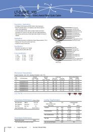
Structure of XLPE <strong>Cable</strong><br />
The XLPE <strong>Cable</strong> has the construction of a conductor (copper or aluminum) insulated with the cross-linked polyethylene and then<br />
shielded with metallic screen (corrugated and seamless aluminum or wire shield), to be covered by PVC or polyethylene for anticorrosion.<br />
Insulation<br />
The insulation material is extruded cross-linked polyethylene.<br />
The conductor screen, the insulation and the insulation screen<br />
mentioned to the following clause are extruded simultaneously<br />
in one process to ensure that the screen and insulation are<br />
intimately bonded together and free from all possibilities of<br />
voids between layers.<br />
The extrusion process is carried out under strictly controlled<br />
atmospheric conditions.<br />
The thickness of the insulation layer is the maximum value<br />
figured out from the design of the impulse voltage and A.C.<br />
voltage.<br />
The conventional cross-linking process by saturated steam has<br />
frequently caused deterioration of the electrical characteristics<br />
of the insulation as treeing phenomena arose when put to use<br />
for long time. But the new process by N2 gas has enabled to<br />
protect the electrical characteristics from being deteriorated and<br />
to lessen the thickness of the insulation and accordingly the<br />
cable’s outer diameter itself.<br />
Insulation Screen<br />
The insulation screen is provided over the insulation by<br />
extruding the semi-conducting compound concentrically and<br />
circularly to minimize the possibility of ionization on the outer<br />
surface of the dielectric.<br />
Metallic Screen<br />
The metallic screen consists of the wire shield, the corrugated<br />
aluminum sheath or the lead sheath. The corrugated aluminum<br />
sheath and the lead sheath is also adopted where the surface<br />
of duct is poor and where moisture is high.<br />
Outer Sheath<br />
To protect the metallic sheath from electrical or chemical<br />
corrosion, it is covered by PE or PVC.
Corrugated Aluminum Sheath <strong>Cable</strong><br />
1. Conductor<br />
2. Conductor Screen<br />
3. XLPE Insulation<br />
4. Insulation Screen<br />
5. Semi-Conducting Tape<br />
6. Corrugated & Seamless<br />
Aluminum Sheath<br />
7. PE or PVC Outer Sheath<br />
Lead Sheath <strong>Cable</strong><br />
Wire Shield <strong>Cable</strong> Copper Laminated <strong>Cable</strong><br />
1. Conductor<br />
2. Conductor Screen<br />
3. XLPE Insulation<br />
4. Insulation Screen<br />
5. Semi-Conducting Tape<br />
6. Copper Wire<br />
Screen<br />
7. Aluminum Laminated<br />
Tape<br />
8. PE or PVC Outer Sheath<br />
1. Conductor<br />
2. Conductor Screen<br />
3. XLPE Insulation<br />
4. Insulation Screen<br />
5. Semi-Conducting Tape<br />
6. Lead Sheath<br />
7. PE or PVC Outer Sheath<br />
1. Conductor<br />
2. Conductor Screen<br />
3. XLPE Insulation<br />
4. Insulation Screen<br />
5. Semi-Conducting Tape<br />
6. Copper Wire<br />
Screen<br />
7. Copper Laminated<br />
Tape<br />
8. PE or PVC Outer Sheath<br />
Design & Construction of XLPE <strong>Cable</strong> 9
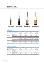
10<br />
Compact<br />
Circular<br />
Manufacturing Process & VCV Line<br />
2.00 Manufacturing Process & VCV Line<br />
Conductor<br />
Drawing<br />
Stranding<br />
Segment<br />
Stranding<br />
Taping<br />
Insulation<br />
Degassing<br />
Taping<br />
Outer<br />
Sheath<br />
Testing<br />
Shipping<br />
Segmental<br />
Compact<br />
The system adopted for insulation of the XLPE <strong>Cable</strong> is VCV and N2 gas is<br />
used for cross linking, and the line is extruded in a vertical type. The<br />
outstanding characteristics of the XLPE <strong>Cable</strong> manufactured in application of<br />
this system are :<br />
1. The insulation has no eccentricity.<br />
2. The cross-linking by use of N2 gas guarantees excellent electrical<br />
characteristics of the insulation.<br />
3. The simultaneous extrusion of the inner and outer semi-conducting layers<br />
and the insulation prevents treeing and other irregularities.<br />
4. Uniformity of quality is maintained of all products as the manufacturing<br />
processes are controlled by computer.<br />
Rip Cord<br />
Paper<br />
Semi Conducting Tape<br />
Semi Conducting Tape<br />
Insulation<br />
Al Billet<br />
Corrugated<br />
Al Sheath<br />
Inner layer<br />
Compound<br />
PVC, PE<br />
Outer Layer<br />
Copper wire<br />
Wire<br />
Shield<br />
Lead<br />
Lead<br />
Sheath
Extrusion<br />
The conductor screen, the insulation and the insulation screen are simultaneously<br />
extruded with the compounds supplied from the clean room.<br />
Cross-Linking and Cooling<br />
The corss-linking takes place in curing zone of A by circulating N2 gas and the<br />
insulation is formed into core through precooling zone of B and cooling zone of C.<br />
Take Up<br />
The cable comes to be wound up again around<br />
the drum to go into the next process.<br />
Pay Off<br />
The conductor wound up around<br />
the drum is set at pay off to run to<br />
metering capstan.<br />
Manufacturing Process & VCV Line 11
12 <strong>Cable</strong> Construction & Continuous Current Ratings<br />
3.00 <strong>Cable</strong> Construction &<br />
Continuous Current Ratings<br />
The continuous current capacity is calculated in accordance with IEC 60287.<br />
Laying Conditions<br />
1) Ground Temperature : 25<br />
2) Depth of Laying : 1.5m<br />
3) Soil Thermal Resistivity : 1.0 m/W<br />
4) Ambient Temperature : 40<br />
5) Max. Conductor Temperature : 90<br />
6) <strong>Cable</strong> Formation : Flat (S=2D)<br />
S : Distance between cables / D : <strong>Cable</strong> diameter<br />
7) Frequency : 50Hz<br />
8) Load factor : 100%<br />
Maximum Permissible Conductor Temperature<br />
Normal Operation Emergency Operation Short Circuit<br />
90 105 250<br />
1) Normal Operation<br />
Normal operation is meant to be maintained through out a given period of<br />
time everyday or continuously, without affecting the operation.<br />
2) Emergency Load<br />
Emergency load is meant to be maintained for a short time under the<br />
condition of system breakdown or under the state of excessively loaded<br />
operation, without causing a defect.<br />
3) Short Circuit<br />
Short circuit is meant to cause no defect of the cable when an irregular<br />
current, flows for short time due to shorting or earthing.
4.00 XLPE Insulated <strong>Cable</strong>s<br />
4.01 36/66 (72.5) kV with Aluminum Sheath<br />
4.02 36/66 (72.5) kV with Lead Sheath<br />
4.03 36/66 (72.5) kV with Copper Wire Shield<br />
4.04 64/110 (123) kV with Aluminum Sheath<br />
4.05 64/110 (123) kV with Lead Sheath<br />
4.06 64/110 (123) kV with Copper Wire Shield<br />
4.07 76/132 (145) kV with Aluminum Sheath<br />
4.08 76/132 (145) kV with Lead Sheath<br />
4.09 76/132 (145) kV with Copper Wire Shield<br />
4.10 87/161 (170) kV with Aluminum Sheath<br />
4.11 87/161 (170) kV with Lead Sheath<br />
4.12 87/161 (170) kV with Copper Wire Shield<br />
4.13 127/230 (245) kV with Aluminum Sheath<br />
4.14 127/230 (245) kV with Lead Sheath<br />
4.15 127/230 (245) kV with Copper Wire Shield<br />
4.16 190/345 (362) kV with Aluminum Sheath<br />
4.17 190/345 (362) kV with Lead Sheath<br />
4.18 220/400 (420) kV with Aluminum Sheath<br />
4.19 220/400 (420) kV with Lead Sheath<br />
4.20 290/500(525)kV with Alumimum Sheath<br />
4.21 290/500(525)kV with Lead Sheath<br />
XLPE Insulated <strong>Cable</strong>s 13
4.01 36/66 (72.5) kV with Aluminum Sheath<br />
Aluminum Sheath<br />
Constructional Data (Nominal Values)<br />
14<br />
XLPE Insulated <strong>Cable</strong>s<br />
Conductor<br />
Cross-Sectional Area Shape Diameter<br />
Thickness of<br />
Conductor<br />
Screen Approx.<br />
mm 2 mm mm<br />
240<br />
300<br />
400<br />
500<br />
630<br />
800<br />
1000<br />
1200<br />
1600<br />
2000<br />
Compact Round<br />
Stranded<br />
Segment Stranded<br />
(Miliken)<br />
Construction<br />
Copper Conductor XLPE Insulation<br />
Aluminum Sheath PE (or PVC) Outer Sheath<br />
Continuous Current Ratings for Single Circuit (A)<br />
Cross-Sectional Area (mm2 In Air<br />
) Direct Buried Pipe Duct<br />
Trefoil Flat (S=2D)<br />
240 524 491 598 671<br />
300 592 556 682 770<br />
400 671 631 781 888<br />
500 762 714 894 1025<br />
630 878 808 1023 1187<br />
800 965 928 1150 1355<br />
1000 1119 1075 1361 1615<br />
1200 1198 1146 1460 1745<br />
1600 1352 1357 1654 2030<br />
2000 1468 1475 1800 2273<br />
Thickness of<br />
Insulation<br />
mm<br />
Thickness of<br />
Insulation<br />
Screen Approx.<br />
mm<br />
Thickness of<br />
Aluminum<br />
Sheath<br />
mm<br />
Thickness of<br />
Outer Sheath<br />
mm<br />
Outer Diameter<br />
of <strong>Cable</strong><br />
mm<br />
Weight of<br />
<strong>Cable</strong><br />
kg / m<br />
Max. DC<br />
Conductor<br />
Resistance at<br />
20<br />
/ km<br />
Capacitance<br />
18.1 1.0 11.0 1.0 1.6 3.5 69 5.5 0.0754 0.20<br />
20.4 1.0 11.0 1.0 1.6 3.5 72 6.3 0.0601 0.21<br />
23.2 1.0 11.0 1.0 1.7 3.5 75 7.2 0.0470 0.23<br />
26.3 1.0 11.0 1.0 1.8 4.0 79 8.6 0.0366 0.25<br />
30.2 1.0 11.0 1.0 1.8 4.0 83 10.1 0.0283 0.28<br />
34.0 1.0 11.0 1.0 1.9 4.0 87 12.0 0.0221 0.30<br />
38.7 1.0 11.0 1.0 2.0 4.0 92 14.4 0.0176 0.33<br />
41.8 1.0 11.0 1.0 2.1 4.5 98 16.7 0.0151 0.36<br />
48.1 1.0 11.0 1.0 2.2 4.5 105 20.9 0.0113 0.40<br />
54.3 1.0 11.0 1.0 2.4 4.5 112 25.4 0.0090 0.44<br />
/ km
4.02 36/66 (72.5) kV with Lead Sheath<br />
Lead Sheath<br />
Constructional Data (Nominal Values)<br />
Conductor<br />
Cross-Sectional Area Shape Diameter<br />
Thickness of<br />
Conductor<br />
Screen Approx.<br />
mm 2 mm mm<br />
240<br />
300<br />
400<br />
500<br />
630<br />
800<br />
1000<br />
1200<br />
1600<br />
2000<br />
Compact Round<br />
Stranded<br />
Segment Stranded<br />
(Miliken)<br />
Construction<br />
Copper Conductor XLPE Insulation<br />
Lead Sheath PE (or PVC) Outer Sheath<br />
Continuous Current Ratings for Single Circuit (A)<br />
Cross-Sectional Area (mm2 In Air<br />
) Direct Buried Pipe Duct<br />
Trefoil Flat (S=2D)<br />
240 535 525 621 706<br />
300 606 567 710 810<br />
400 691 646 822 942<br />
500 787 733 951 1098<br />
630 898 833 1096 1274<br />
800 1008 958 1243 1462<br />
1000 1184 1121 1505 1759<br />
1200 1282 1208 1648 1938<br />
1600 1469 1434 1906 2282<br />
2000 1626 1585 2130 2597<br />
Thickness of<br />
Insulation<br />
mm<br />
Thickness of<br />
Insulation<br />
Screen Approx.<br />
mm<br />
Thickness of<br />
Lead Sheath<br />
mm<br />
Thickness of<br />
Outer Sheath<br />
mm<br />
Outer Diameter<br />
of <strong>Cable</strong><br />
mm<br />
Weight of<br />
<strong>Cable</strong><br />
kg / m<br />
Max. DC<br />
Conductor<br />
Resistance at<br />
20<br />
/ km<br />
Capacitance<br />
18.1 1.0 11.0 1.0 2.1 3.5 62 8.1 0.0754 0.20<br />
20.4 1.0 11.0 1.0 2.2 3.5 64 9.1 0.0601 0.21<br />
23.2 1.0 11.0 1.0 2.3 3.5 67 10.5 0.0470 0.23<br />
26.3 1.0 11.0 1.0 2.4 4.0 72 12.5 0.0366 0.25<br />
30.2 1.0 11.0 1.0 2.4 4.0 76 14.2 0.0283 0.28<br />
34.0 1.0 11.0 1.0 2.6 4.0 80 16.9 0.0221 0.30<br />
38.7 1.0 11.0 1.0 2.7 4.0 85 19.9 0.0176 0.33<br />
41.8 1.0 11.0 1.0 2.8 4.5 91 23.0 0.0151 0.36<br />
48.1 1.0 11.0 1.0 3.0 4.5 97 28.0 0.0113 0.40<br />
54.3 1.0 11.0 1.0 3.2 4.5 104 33.4 0.0090 0.44<br />
/ km<br />
XLPE Insulated <strong>Cable</strong>s 15<br />
36/66 (72.5) kV 64/110 (123) kV 76/132 (145) kV 87/161 (170) kV 127/230 (245) kV 190/345 (362) 220/400 (420) kV 290/500 (525) kV
4.03 36/66 (72.5) kV with Copper Wire Shield<br />
Copper Wire Shield<br />
Constructional Data (Nominal Values)<br />
16<br />
XLPE Insulated <strong>Cable</strong>s<br />
Conductor<br />
Cross-Sectional Area Shape Diameter<br />
Thickness of<br />
Conductor<br />
Screen Approx.<br />
mm 2 mm mm<br />
240<br />
300<br />
400<br />
500<br />
630<br />
800<br />
1000<br />
1200<br />
1600<br />
2000<br />
Compact Round<br />
Stranded<br />
Segment Stranded<br />
(Miliken)<br />
Construction<br />
Copper Conductor XLPE Insulation<br />
Copper Wire Shield PE (or PVC) Outer Sheath<br />
Continuous Current Ratings for Single Circuit (A)<br />
Cross-Sectional Area (mm2 In Air<br />
) Direct Buried Pipe Duct<br />
Trefoil Flat (S=2D)<br />
240 530 483 606 692<br />
300 599 544 693 795`<br />
400 683 616 802 925<br />
500 780 729 929 1075<br />
630 886 828 1066 1247<br />
800 997 929 1210 1432<br />
1000 1173 1087 1473 1728<br />
1200 1270 1173 1611 1894<br />
1600 1465 1375 1883 2245<br />
2000 1627 1530 2111 2556<br />
Thickness of<br />
Insulation<br />
mm<br />
Thickness of<br />
Insulation<br />
Screen Approx.<br />
mm<br />
Diameter &<br />
Number of<br />
Copper Wires<br />
mm x No.<br />
Thickness of<br />
Outer Sheath<br />
mm<br />
Outer Diameter<br />
of <strong>Cable</strong><br />
mm<br />
Weight of<br />
<strong>Cable</strong><br />
kg / m<br />
Max. DC<br />
Conductor<br />
Resistance at<br />
20<br />
/ km<br />
Capacitance<br />
18.1 1.0 11.0 1.0 1.2 x 40 3.5 58 4.4 0.0754 0.20<br />
20.4 1.0 11.0 1.0 1.2 x 40 3.5 60 5.1 0.0601 0.21<br />
23.2 1.0 11.0 1.0 1.2 x 40 3.5 63 5.9 0.0470 0.23<br />
26.3 1.0 11.0 1.0 1.2 x 40 4.0 66 7.2 0.0366 0.25<br />
30.2 1.0 11.0 1.0 1.2 x 40 4.0 71 8.6 0.0283 0.28<br />
34.0 1.0 11.0 1.0 1.2 x 40 4.0 75 10.4 0.0221 0.30<br />
38.7 1.0 11.0 1.0 1.2 x 40 4.0 80 12.7 0.0176 0.33<br />
41.8 1.0 11.0 1.0 1.2 x 40 4.5 85 14.7 0.0151 0.36<br />
48.1 1.0 11.0 1.0 1.2 x 40 4.5 91 18.7 0.0113 0.40<br />
54.3 1.0 11.0 1.0 1.2 x 40 4.5 97 22.7 0.0090 0.44<br />
/ km
4.04 64/110 (123) kV with Aluminum Sheath<br />
Aluminum Sheath<br />
Constructional Data (Nominal Values)<br />
Conductor<br />
Cross-Sectional Area Shape Diameter<br />
Thickness of<br />
Conductor<br />
Screen Approx.<br />
mm 2 mm mm<br />
240<br />
300<br />
400<br />
500<br />
630<br />
800<br />
1000<br />
1200<br />
1600<br />
2000<br />
2500<br />
Compact Round<br />
Stranded<br />
Segment<br />
Stranded (Miliken)<br />
Construction<br />
Copper Conductor XLPE Insulation<br />
Aluminum Sheath PE (or PVC) Outer Sheath<br />
Continuous Current Ratings for Single Circuit (A)<br />
Cross-Sectional Area (mm2 In Air<br />
) Direct Buried Pipe Duct<br />
Trefoil Flat (S=2D)<br />
240 520 491 592 657<br />
300 587 550 677 755<br />
400 667 639 775 873<br />
500 758 725 889 1006<br />
630 860 821 1020 1169<br />
800 961 915 1147 1333<br />
1000 1109 1057 1346 1581<br />
1200 1187 1180 1451 1717<br />
1600 1338 1332 1635 1995<br />
2000 1458 1447 1787 2236<br />
2500 1538 1526 1885 2358<br />
Thickness of<br />
Insulation<br />
mm<br />
Thickness of<br />
Insulation<br />
Screen Approx.<br />
mm<br />
Thickness of<br />
Aluminum<br />
Sheath<br />
mm<br />
Thickness of<br />
Outer Sheath<br />
mm<br />
Outer Diameter<br />
of <strong>Cable</strong><br />
mm<br />
Weight of<br />
<strong>Cable</strong><br />
kg / m<br />
Max. DC<br />
Conductor<br />
Resistance at<br />
20<br />
/ km<br />
Capacitance<br />
18.1 1.2 14.0 1.0 1.7 3.5 76 6.3 0.0754 0.17<br />
20.4 1.2 14.0 1.0 1.8 3.5 78 7.0 0.0601 0.18<br />
23.2 1.2 14.0 1.0 1.8 3.5 81 8.0 0.0470 0.20<br />
26.3 1.2 14.0 1.0 1.9 4.0 86 9.3 0.0366 0.21<br />
30.2 1.2 14.0 1.0 2.0 4.0 90 11.0 0.0283 0.23<br />
34.0 1.2 14.0 1.0 2.0 4.0 94 12.9 0.0221 0.25<br />
38.7 1.2 14.0 1.0 2.1 4.0 99 15.4 0.0176 0.28<br />
41.8 1.2 14.0 1.0 2.2 4.5 104 17.7 0.0151 0.30<br />
48.1 1.2 14.0 1.0 2.4 4.5 111 22.1 0.0113 0.33<br />
54.3 1.2 14.0 1.0 2.5 4.5 118 26.5 0.0090 0.36<br />
63.0 1.2 14.0 1.0 2.6 4.5 128 33.0 0.0072 0.40<br />
/ km<br />
XLPE Insulated <strong>Cable</strong>s 17<br />
36/66 (72.5) kV 64/110 (123) kV 76/132 (145) kV 87/161 (170) kV 127/230 (245) kV 190/345 (362) 220/400 (420) kV 290/500 (525) kV
4.05 64/110 (123) kV with Lead Sheath<br />
Lead Sheath<br />
Constructional Data (Nominal Values)<br />
18<br />
XLPE Insulated <strong>Cable</strong>s<br />
Conductor<br />
Cross-Sectional Area Shape Diameter<br />
Thickness of<br />
Conductor<br />
Screen Approx.<br />
mm 2 mm mm<br />
240<br />
300<br />
400<br />
500<br />
630<br />
800<br />
1000<br />
1200<br />
1600<br />
2000<br />
2500<br />
Compact Round<br />
Stranded<br />
Segment Stranded<br />
(Miliken)<br />
Construction<br />
Copper Conductor XLPE Insulation<br />
Lead Sheath PE (or PVC) Outer Sheath<br />
Continuous Current Ratings for Single Circuit (A)<br />
Cross-Sectional Area (mm2 In Air<br />
) Direct Buried Pipe Duct<br />
Trefoil Flat (S=2D)<br />
240 533 498 617 692<br />
300 602 563 705 794<br />
400 687 654 816 923<br />
500 782 744 939 1068<br />
630 891 846 1083 1243<br />
800 1001 949 1229 1425<br />
1000 1176 1108 1486 1718<br />
1200 1269 1235 1612 1871<br />
1600 1455 1415 1870 2206<br />
2000 1609 1562 2087 2505<br />
2500 1695 1647 2201 2642<br />
Thickness of<br />
Insulation<br />
mm<br />
Thickness of<br />
Insulation<br />
Screen Approx.<br />
mm<br />
Thickness of<br />
Lead Sheath<br />
mm<br />
Thickness of<br />
Outer Sheath<br />
mm<br />
Outer Diameter<br />
of <strong>Cable</strong><br />
mm<br />
Weight of<br />
<strong>Cable</strong><br />
kg / m<br />
Max. DC<br />
Conductor<br />
Resistance at<br />
20<br />
/ km<br />
Capacitance<br />
18.1 1.2 14.0 1.0 2.3 3.5 68 9.6 0.0754 0.17<br />
20.4 1.2 14.0 1.0 2.4 3.5 71 10.9 0.0601 0.18<br />
23.2 1.2 14.0 1.0 2.5 3.5 74 12.3 0.0470 0.20<br />
26.3 1.2 14.0 1.0 2.5 4.0 78 13.8 0.0366 0.21<br />
30.2 1.2 14.0 1.0 2.6 4.0 82 16.0 0.0283 0.23<br />
34.0 1.2 14.0 1.0 2.7 4.0 86 18.5 0.0221 0.25<br />
38.7 1.2 14.0 1.0 2.9 4.0 92 21.9 0.0176 0.28<br />
41.8 1.2 14.0 1.0 3.0 4.5 97 24.7 0.0151 0.30<br />
48.1 1.2 14.0 1.0 3.2 4.5 103 30.1 0.0113 0.33<br />
54.3 1.2 14.0 1.0 3.4 4.5 110 35.7 0.0090 0.36<br />
63.0 1.2 14.0 1.0 3.6 4.5 118 42.0 0.0072 0.40<br />
/ km
4.06 64/110 (123) kV with Copper Wire Shield<br />
Copper Wire Shield<br />
Constructional Data (Nominal Values)<br />
Conductor<br />
Cross-Sectional Area Shape Diameter<br />
Thickness of<br />
Conductor<br />
Screen Approx.<br />
mm 2 mm mm<br />
240<br />
300<br />
400<br />
500<br />
630<br />
800<br />
1000<br />
1200<br />
1600<br />
2000<br />
2500<br />
Compact Round<br />
Stranded<br />
Segment Stranded<br />
(Miliken)<br />
Construction<br />
Copper Conductor XLPE Insulation<br />
Copper Wire Shield PE (or PVC) Outer Sheath<br />
Continuous Current Ratings for Single Circuit (A)<br />
Cross-Sectional Area (mm2 In Air<br />
) Direct Buried Pipe Duct<br />
Trefoil Flat (S=2D)<br />
240 528 495 605 682<br />
300 597 559 692 783<br />
400 681 650 800 909<br />
500 775 739 922 1053<br />
630 884 841 1065 1226<br />
800 994 945 1208 1406<br />
1000 1169 1106 1465 1695<br />
1200 1264 1231 1595 1849<br />
1600 1456 1415 1860 2185<br />
2000 1618 1570 2089 2487<br />
2500 1706 1656 2203 2623<br />
Thickness of<br />
Insulation<br />
mm<br />
Thickness of<br />
Insulation<br />
Screen Approx.<br />
mm<br />
Diameter &<br />
Number of<br />
Copper Wires<br />
mm x No.<br />
Thickness of<br />
Outer Sheath<br />
mm<br />
Outer Diameter<br />
of <strong>Cable</strong><br />
mm<br />
Weight of<br />
<strong>Cable</strong><br />
kg / m<br />
Max. DC<br />
Conductor<br />
Resistance at<br />
20<br />
/ km<br />
Capacitance<br />
18.1 1.2 14.0 1.0 1.2 x 40 3.5 64 5.0 0.0754 0.17<br />
20.4 1.2 14.0 1.0 1.2 x 40 3.5 66 5.7 0.0601 0.18<br />
23.2 1.2 14.0 1.0 1.2 x 40 3.5 69 6.6 0.0470 0.20<br />
26.3 1.2 14.0 1.0 1.2 x 40 4.0 73 7.9 0.0366 0.21<br />
30.2 1.2 14.0 1.0 1.2 x 40 4.0 77 9.4 0.0283 0.23<br />
34.0 1.2 14.0 1.0 1.2 x 40 4.0 81 11.2 0.0221 0.25<br />
38.7 1.2 14.0 1.0 1.2 x 40 4.0 86 13.6 0.0176 0.28<br />
41.8 1.2 14.0 1.0 1.2 x 40 4.5 91 15.6 0.0151 0.30<br />
48.1 1.2 14.0 1.0 1.2 x 40 4.5 97 19.6 0.0113 0.33<br />
54.3 1.2 14.0 1.0 1.2 x 40 4.5 103 23.7 0.0090 0.36<br />
63.0 1.2 14.0 1.0 1.2 x 40 4.5 111 29.0 0.0072 0.40<br />
/ km<br />
XLPE Insulated <strong>Cable</strong>s 19<br />
36/66 (72.5) kV 64/110 (123) kV 76/132 (145) kV 87/161 (170) kV 127/230 (245) kV 190/345 (362) 220/400 (420) kV 290/500 (525) kV
4.07 76/132 (145) kV with Aluminum Sheath<br />
Aluminum Sheath<br />
Constructional Data (Nominal Values)<br />
20<br />
XLPE Insulated <strong>Cable</strong>s<br />
Conductor<br />
Cross-Sectional Area Shape Diameter<br />
Thickness of<br />
Conductor<br />
Screen Approx.<br />
mm 2 mm mm<br />
240<br />
300<br />
400<br />
500<br />
630<br />
800<br />
1000<br />
1200<br />
1600<br />
2000<br />
2500<br />
Compact Round<br />
Stranded<br />
Segment Stranded<br />
(Miliken)<br />
Construction<br />
Copper Conductor XLPE Insulation<br />
Aluminum Sheath PE (or PVC) Outer Sheath<br />
Continuous Current Ratings for Single Circuit (A)<br />
Cross-Sectional Area (mm2 In Air<br />
) Direct Buried Pipe Duct<br />
Trefoil Flat (S=2D)<br />
240 519 486 589 649<br />
300 585 547 671 742<br />
400 665 635 770 858<br />
500 755 716 883 992<br />
630 856 814 1011 1151<br />
800 956 942 1137 1313<br />
1000 1103 1093 1333 1555<br />
1200 1185 1170 1439 1695<br />
1600 1333 1324 1627 1972<br />
2000 1452 1435 1777 2211<br />
2500 1530 1512 1872 2330<br />
Thickness of<br />
Insulation<br />
mm<br />
Thickness of<br />
Insulation<br />
Screen Approx.<br />
mm<br />
Thickness of<br />
Aluminum<br />
Sheath<br />
mm<br />
Thickness of<br />
Outer Sheath<br />
mm<br />
Outer Diameter<br />
of <strong>Cable</strong><br />
mm<br />
Weight of<br />
<strong>Cable</strong><br />
kg / m<br />
Max. DC<br />
Conductor<br />
Resistance at<br />
20<br />
/ km<br />
Capacitance<br />
18.1 1.5 16.0 1.3 1.8 4.5 83 7.1 0.0754 0.16<br />
20.4 1.5 16.0 1.3 1.8 4.5 86 7.9 0.0601 0.17<br />
23.2 1.5 16.0 1.3 1.9 4.5 89 8.9 0.0470 0.18<br />
26.3 1.5 16.0 1.3 2.0 4.5 92 10.2 0.0366 0.20<br />
30.2 1.5 16.0 1.3 2.1 4.5 97 11.9 0.0283 0.21<br />
34.0 1.5 16.0 1.3 2.2 4.5 101 14.0 0.0221 0.23<br />
38.7 1.5 16.0 1.3 2.2 4.5 106 16.6 0.0176 0.25<br />
41.8 1.5 16.0 1.3 2.3 4.5 110 18.6 0.0151 0.27<br />
48.1 1.5 16.0 1.3 2.4 4.5 116 22.9 0.0113 0.30<br />
54.3 1.5 16.0 1.3 2.6 4.5 124 27.4 0.0090 0.32<br />
63.0 1.5 16.0 1.3 2.8 4.5 131 34.3 0.0072 0.36<br />
/ km
4.08 76/132 (145) kV with Lead Sheath<br />
Lead Sheath<br />
Constructional Data (Nominal Values)<br />
Conductor<br />
Cross-Sectional Area Shape Diameter<br />
Thickness of<br />
Conductor<br />
Screen Approx.<br />
mm 2 mm mm<br />
240<br />
300<br />
400<br />
500<br />
630<br />
800<br />
1000<br />
1200<br />
1600<br />
2000<br />
2500<br />
Compact Round<br />
Stranded<br />
Segment Stranded<br />
(Miliken)<br />
Construction<br />
Copper Conductor XLPE Insulation<br />
Lead Sheath PE (or PVC) Outer Sheath<br />
Continuous Current Ratings for Single Circuit (A)<br />
Cross-Sectional Area (mm2 In Air<br />
) Direct Buried Pipe Duct<br />
Trefoil Flat (S=2D)<br />
240 530 495 612 679<br />
300 600 559 702 781<br />
400 684 636 808 904<br />
500 780 727 934 1050<br />
630 889 840 1077 1222<br />
800 997 941 1222 1400<br />
1000 1170 1100 1469 1681<br />
1200 1264 1226 1599 1842<br />
1600 1449 1404 1853 2168<br />
2000 1600 1548 2064 2460<br />
2500 1686 1631 2175 2592<br />
Thickness of<br />
Insulation<br />
mm<br />
Thickness of<br />
Insulation<br />
Screen Approx.<br />
mm<br />
Thickness of<br />
Lead Sheath<br />
mm<br />
Thickness of<br />
Outer Sheath<br />
mm<br />
Outer Diameter<br />
of <strong>Cable</strong><br />
mm<br />
Weight of<br />
<strong>Cable</strong><br />
kg / m<br />
Max. DC<br />
Conductor<br />
Resistance at<br />
20<br />
/ km<br />
Capacitance<br />
18.1 1.5 16.0 1.3 2.4 4.5 76 11.2 0.0754 0.16<br />
20.4 1.5 16.0 1.3 2.5 4.5 78 12.3 0.0601 0.17<br />
23.2 1.5 16.0 1.3 2.6 4.5 81 13.8 0.0470 0.18<br />
26.3 1.5 16.0 1.3 2.7 4.5 85 15.6 0.0366 0.20<br />
30.2 1.5 16.0 1.3 2.7 4.5 88 17.5 0.0283 0.21<br />
34.0 1.5 16.0 1.3 2.9 4.5 93 20.4 0.0221 0.23<br />
38.7 1.5 16.0 1.3 3.0 4.5 98 23.6 0.0176 0.25<br />
41.8 1.5 16.0 1.3 3.1 4.5 102 26.5 0.0151 0.27<br />
48.1 1.5 16.0 1.3 3.3 4.5 108 31.7 0.0113 0.30<br />
54.3 1.5 16.0 1.3 3.5 4.5 115 37.7 0.0090 0.32<br />
63.0 1.5 16.0 1.3 3.7 4.5 123 44.3 0.0072 0.36<br />
/ km<br />
XLPE Insulated <strong>Cable</strong>s 21<br />
36/66 (72.5) kV 64/110 (123) kV 76/132 (145) kV 87/161 (170) kV 127/230 (245) kV 190/345 (362) 220/400 (420) kV 290/500 (525) kV
4.09 76/132 (145) kV with Copper Wire Shield<br />
Copper Wire Shield<br />
Constructional Data (Nominal Values)<br />
22<br />
XLPE Insulated <strong>Cable</strong>s<br />
Conductor<br />
Cross-Sectional Area Shape Diameter<br />
Thickness of<br />
Conductor<br />
Screen Approx.<br />
mm 2 mm mm<br />
240<br />
300<br />
400<br />
500<br />
630<br />
800<br />
1000<br />
1200<br />
1600<br />
2000<br />
2500<br />
Compact Round<br />
Stranded<br />
Segment Stranded<br />
(Miliken)<br />
Construction<br />
Copper Conductor XLPE Insulation<br />
Copper Wire Shield PE (or PVC) Outer Sheath<br />
Continuous Current Ratings for Single Circuit (A)<br />
Cross-Sectional Area (mm2 In Air<br />
) Direct Buried Pipe Duct<br />
Trefoil Flat (S=2D)<br />
240 525 492 601 673<br />
300 593 555 688 774<br />
400 675 632 792 896<br />
500 767 716 908 1033<br />
630 872 811 1045 1200<br />
800 979 932 1182 1374<br />
1000 1145 1087 1420 1649<br />
1200 1233 1212 1539 1801<br />
1600 1414 1388 1784 2125<br />
2000 1569 1532 2003 2418<br />
2500 1653 1614 2111 2548<br />
Thickness of<br />
Insulation<br />
mm<br />
Thickness of<br />
Insulation<br />
Screen Approx.<br />
mm<br />
Diameter &<br />
Number of<br />
Copper Wires<br />
mm x No.<br />
Thickness of<br />
Outer Sheath<br />
mm<br />
Outer Diameter<br />
of <strong>Cable</strong><br />
mm<br />
Weight of<br />
<strong>Cable</strong><br />
kg / m<br />
Max. DC<br />
Conductor<br />
Resistance at<br />
20<br />
/ km<br />
Capacitance<br />
18.1 1.5 16.0 1.3 1.5 x 80 4.5 70 6.5 0.0754 0.16<br />
20.4 1.5 16.0 1.3 1.5 x 80 4.5 72 7.1 0.0601 0.17<br />
23.2 1.5 16.0 1.3 1.5 x 80 4.5 75 8.1 0.0470 0.18<br />
26.3 1.5 16.0 1.3 1.5 x 80 4.5 80 9.5 0.0366 0.20<br />
30.2 1.5 16.0 1.3 1.5 x 80 4.5 84 11.0 0.0283 0.21<br />
34.0 1.5 16.0 1.3 1.5 x 80 4.5 88 12.9 0.0221 0.23<br />
38.7 1.5 16.0 1.3 1.5 x 80 4.5 93 15.3 0.0176 0.25<br />
41.8 1.5 16.0 1.3 1.5 x 80 4.5 96 17.1 0.0151 0.27<br />
48.1 1.5 16.0 1.3 1.5 x 80 4.5 102 21.2 0.0113 0.30<br />
54.3 1.5 16.0 1.3 1.5 x 80 4.5 110 25.8 0.0090 0.32<br />
63.0 1.5 16.0 1.3 1.5 x 80 4.5 118 31.4 0.0072 0.36<br />
/ km
4.10 87/161 (170) kV with Aluminum Sheath<br />
Aluminum Sheath<br />
Constructional Data (Nominal Values)<br />
Conductor<br />
Cross-Sectional Area Shape Diameter<br />
Thickness of<br />
Conductor<br />
Screen Approx.<br />
mm 2 mm mm<br />
300<br />
400<br />
500<br />
630<br />
800<br />
1000<br />
1200<br />
1600<br />
2000<br />
2500<br />
Compact Round<br />
Stranded<br />
Segment Stranded<br />
(Miliken)<br />
Construction<br />
Copper Conductor XLPE Insulation<br />
Aluminum Sheath PE (or PVC) Outer Sheath<br />
Continuous Current Ratings for Single Circuit (A)<br />
Cross-Sectional Area (mm2 In Air<br />
) Direct Buried Pipe Duct<br />
Trefoil Flat (S=2D)<br />
300 584 558 669 740<br />
400 664 634 768 855<br />
500 754 718 879 988<br />
630 853 811 1009 1146<br />
800 953 938 1134 1307<br />
1000 1100 1087 1328 1548<br />
1200 1179 1163 1429 1684<br />
1600 1331 1311 1627 1967<br />
2000 1447 1485 1774 2199<br />
2500 1523 1563 1868 2315<br />
Thickness of<br />
Insulation<br />
mm<br />
Thickness of<br />
Insulation<br />
Screen Approx.<br />
mm<br />
Thickness of<br />
Aluminum<br />
Sheath<br />
mm<br />
Thickness of<br />
Outer Sheath<br />
mm<br />
Outer Diameter<br />
of <strong>Cable</strong><br />
mm<br />
Weight of<br />
<strong>Cable</strong><br />
kg / m<br />
Max. DC<br />
Conductor<br />
Resistance at<br />
20<br />
/ km<br />
Capacitance<br />
20.4 1.5 17 1.3 1.9 4.5 87 8.4 0.0601 0.16<br />
23.2 1.5 17 1.3 1.9 4.5 91 9.4 0.0470 0.18<br />
26.3 1.5 17 1.3 2.0 4.5 94 10.7 0.0366 0.19<br />
30.2 1.5 17 1.3 2.1 4.5 98 12.3 0.0283 0.21<br />
34.0 1.5 17 1.3 2.2 4.5 102 14.4 0.0221 0.22<br />
38.7 1.5 17 1.3 2.3 4.5 108 17.0 0.0176 0.24<br />
41.8 1.5 17 1.3 2.3 4.5 111 19.0 0.0151 0.26<br />
48.1 1.5 17 1.3 2.5 4.5 119 23.5 0.0113 0.28<br />
54.3 1.5 17 1.3 2.6 4.5 125 28.0 0.0090 0.31<br />
63.0 1.5 17 1.3 2.8 4.5 134 34.5 0.0072 0.34<br />
/ km<br />
XLPE Insulated <strong>Cable</strong>s 23<br />
36/66 (72.5) kV 64/110 (123) kV 76/132 (145) kV 87/161 (170) kV 127/230 (245) kV 190/345 (362) 220/400 (420) kV 290/500 (525) kV
4.11 87/161 (170) kV with Lead Sheath<br />
Lead Sheath<br />
Constructional Data (Nominal Values)<br />
24<br />
XLPE Insulated <strong>Cable</strong>s<br />
Conductor<br />
Cross-Sectional Area Shape Diameter<br />
Thickness of<br />
Conductor<br />
Screen Approx.<br />
mm 2 mm mm<br />
300<br />
400<br />
500<br />
630<br />
800<br />
1000<br />
1200<br />
1600<br />
2000<br />
2500<br />
Compact Round<br />
Stranded<br />
Segment Stranded<br />
(Miliken)<br />
Construction<br />
Copper Conductor XLPE Insulation<br />
Lead Sheath PE (or PVC) Outer Sheath<br />
Continuous Current Ratings for Single Circuit (A)<br />
Cross-Sectional Area (mm2 In Air<br />
) Direct Buried Pipe Duct<br />
Trefoil Flat (S=2D)<br />
300 598 557 698 775<br />
400 682 648 805 898<br />
500 777 736 928 1042<br />
630 886 836 1073 1214<br />
800 996 939 1218 1391<br />
1000 1168 1131 1464 1670<br />
1200 1259 1221 1589 1825<br />
1600 1445 1398 1845 2152<br />
2000 1597 1541 2060 2445<br />
2500 1681 1622 2169 2574<br />
Thickness of<br />
Insulation<br />
mm<br />
Thickness of<br />
Insulation<br />
Screen Approx.<br />
mm<br />
Thickness of<br />
Lead Sheath<br />
mm<br />
Thickness of<br />
Outer Sheath<br />
mm<br />
Outer Diameter<br />
of <strong>Cable</strong><br />
mm<br />
Weight of<br />
<strong>Cable</strong><br />
kg / m<br />
Max. DC<br />
Conductor<br />
Resistance at<br />
20<br />
/ km<br />
Capacitance<br />
20.4 1.5 17 1.3 2.5 4.5 80 12.5 0.0601 0.16<br />
23.2 1.5 17 1.3 2.6 4.5 83 14.0 0.0470 0.18<br />
26.3 1.5 17 1.3 2.7 4.5 86 15.7 0.0366 0.19<br />
30.2 1.5 17 1.3 2.8 4.5 90 18.0 0.0283 0.21<br />
34.0 1.5 17 1.3 2.9 4.5 94 20.5 0.0221 0.22<br />
38.7 1.5 17 1.3 3.0 4.5 100 23.8 0.0176 0.24<br />
41.8 1.5 17 1.3 3.2 4.5 103 26.7 0.0151 0.26<br />
48.1 1.5 17 1.3 3.4 4.5 110 32.2 0.0113 0.28<br />
54.3 1.5 17 1.3 3.6 4.5 116 37.9 0.0090 0.31<br />
63.0 1.5 17 1.3 3.7 4.5 124 44.9 0.0072 0.34<br />
/ km
4.12 87/161 (170) kV with Copper Wire Shield<br />
Copper Wire Shield<br />
Constructional Data (Nominal Values)<br />
Conductor<br />
Cross-Sectional Area Shape Diameter<br />
Thickness of<br />
Conductor<br />
Screen Approx.<br />
mm 2 mm mm<br />
300<br />
400<br />
500<br />
630<br />
800<br />
1000<br />
1200<br />
1600<br />
2000<br />
2500<br />
Compact Round<br />
Stranded<br />
Segment Stranded<br />
(Miliken)<br />
Construction<br />
Copper Conductor XLPE Insulation<br />
Copper Wire Shield PE (or PVC) Outer Sheath<br />
Continuous Current Ratings for Single Circuit (A)<br />
Cross-Sectional Area (mm2 In Air<br />
) Direct Buried Pipe Duct<br />
Trefoil Flat (S=2D)<br />
300 591 553 684 765<br />
400 673 629 789 887<br />
500 766 713 907 1027<br />
630 871 829 1043 1193<br />
800 977 928 1181 1367<br />
1000 1143 1081 1415 1639<br />
1200 1232 1208 1535 1790<br />
1600 1404 1382 1765 2100<br />
2000 1554 1523 1973 2384<br />
2500 1636 1603 2077 2510<br />
Thickness of<br />
Insulation<br />
mm<br />
Thickness of<br />
Insulation<br />
Screen Approx.<br />
mm<br />
Diameter &<br />
Number of<br />
Copper Wires<br />
mm x No.<br />
Thickness of<br />
Outer Sheath<br />
mm<br />
Outer Diameter<br />
of <strong>Cable</strong><br />
mm<br />
Weight of<br />
<strong>Cable</strong><br />
kg / m<br />
Max. DC<br />
Conductor<br />
Resistance at<br />
20<br />
/ km<br />
Capacitance<br />
20.4 1.5 17 1.3 1.5 x 80 4.5 72 6.3 0.0601 0.21<br />
23.2 1.5 17 1.3 1.5 x 80 4.5 75 7.2 0.0470 0.23<br />
26.3 1.5 17 1.3 1.5 x 80 4.5 79 8.6 0.0366 0.25<br />
30.2 1.5 17 1.3 1.5 x 80 4.5 83 10.1 0.0283 0.28<br />
34.0 1.5 17 1.3 1.5 x 80 4.5 87 12.0 0.0221 0.30<br />
38.7 1.5 17 1.3 1.5 x 80 4.5 92 14.4 0.0176 0.33<br />
41.8 1.5 17 1.3 1.5 x 80 4.5 98 16.7 0.0151 0.36<br />
48.1 1.5 17 1.3 1.5 x 80 4.5 105 20.9 0.0113 0.40<br />
54.3 1.5 17 1.3 1.5 x 80 4.5 112 25.4 0.0090 0.44<br />
63.0 1.5 17 1.3 1.5 x 80 4.5 118 31.1 0.0072 0.34<br />
/ km<br />
XLPE Insulated <strong>Cable</strong>s 25<br />
36/66 (72.5) kV 64/110 (123) kV 76/132 (145) kV 87/161 (170) kV 127/230 (245) kV 190/345 (362) 220/400 (420) kV 290/500 (525) kV
4.13 127/230 (245) kV with Aluminum Sheath<br />
Aluminum Sheath<br />
Constructional Data (Nominal Values)<br />
26<br />
XLPE Insulated <strong>Cable</strong>s<br />
Conductor<br />
Cross-Sectional Area Shape Diameter<br />
Thickness of<br />
Conductor<br />
Screen Approx.<br />
mm 2 mm mm<br />
400<br />
500<br />
630<br />
800<br />
1000<br />
1200<br />
1600<br />
2000<br />
2500<br />
Compact Round<br />
Stranded<br />
Segment Stranded<br />
(Miliken)<br />
Construction<br />
Copper Conductor XLPE Insulation<br />
Aluminum Sheath PE (or PVC) Outer Sheath<br />
Continuous Current Ratings for Single Circuit (A)<br />
Cross-Sectional Area (mm2 In Air<br />
) Direct Buried Pipe Duct<br />
Trefoil Flat (S=2D)<br />
400 657 641 757 836<br />
500 745 725 866 962<br />
630 843 822 989 1111<br />
800 943 916 1116 1268<br />
1000 1090 1057 1310 1505<br />
1200 1165 1131 1403 1631<br />
1600 1316 1322 1596 1902<br />
2000 1438 1440 1758 2143<br />
2500 1512 1514 1849 2254<br />
Thickness of<br />
Insulation<br />
mm<br />
Thickness of<br />
Insulation<br />
Screen Approx.<br />
mm<br />
Thickness of<br />
Aluminum<br />
Sheath<br />
mm<br />
Thickness of<br />
Outer Sheath<br />
mm<br />
Outer Diameter<br />
of <strong>Cable</strong><br />
mm<br />
Weight of<br />
<strong>Cable</strong><br />
kg / m<br />
Max. DC<br />
Conductor<br />
Resistance at<br />
20<br />
/ km<br />
Capacitance<br />
23.2 1.5 23.0 1.3 2.2 4.5 104 11.0 0.0470 0.14<br />
26.3 1.5 23.0 1.3 2.3 4.5 108 12.1 0.0366 0.15<br />
30.2 1.5 23.0 1.3 2.4 4.5 112 14.2 0.0283 0.17<br />
34.0 1.5 23.0 1.3 2.4 4.5 116 15.8 0.0221 0.18<br />
34.0 1.5 23.0 1.3 2.4 4.5 116 15.8 0.0221 0.18<br />
41.8 1.5 23.0 1.3 2.6 5.0 126 21.5 0.0151 0.21<br />
48.1 1.5 23.0 1.3 2.7 5.0 133 26.0 0.0113 0.23<br />
54.3 1.5 23.0 1.3 2.8 5.0 139 30.7 0.0090 0.24<br />
63.0 1.5 23.0 1.3 3.0 5.0 148 37.8 0.0072 0.27<br />
/ km
4.14 127/230 (245) kV with Lead Sheath<br />
Lead Sheath<br />
Constructional Data (Nominal Values)<br />
Conductor<br />
Cross-Sectional Area Shape Diameter<br />
Thickness of<br />
Conductor<br />
Screen Approx.<br />
mm 2 mm mm<br />
400<br />
500<br />
630<br />
800<br />
1000<br />
1200<br />
1600<br />
2000<br />
2500<br />
Compact Round<br />
Stranded<br />
Segment Stranded<br />
(Miliken)<br />
Construction<br />
Copper Conductor XLPE Insulation<br />
Lead Sheath PE (or PVC) Outer Sheath<br />
Continuous Current Ratings for Single Circuit (A)<br />
Cross-Sectional Area (mm2 In Air<br />
) Direct Buried Pipe Duct<br />
Trefoil Flat (S=2D)<br />
400 676 638 793 871<br />
500 770 745 914 1010<br />
630 876 847 1054 1173<br />
800 986 950 1196 1343<br />
1000 1153 1108 1429 1606<br />
1200 1243 1194 1552 1757<br />
1600 1424 1401 1797 2068<br />
2000 1571 1545 2004 2342<br />
2500 1652 1625 2108 2463<br />
Thickness of<br />
Insulation<br />
mm<br />
Thickness of<br />
Insulation<br />
Screen Approx.<br />
mm<br />
Thickness of<br />
Lead Sheath<br />
mm<br />
Thickness of<br />
Outer Sheath<br />
mm<br />
Outer Diameter<br />
of <strong>Cable</strong><br />
mm<br />
Weight of<br />
<strong>Cable</strong><br />
kg / m<br />
Max. DC<br />
Conductor<br />
Resistance at<br />
20<br />
/ km<br />
Capacitance<br />
23.2 1.5 23.0 1.3 3.2 4.5 96 17.9 0.0470 0.14<br />
26.3 1.5 23.0 1.3 3.3 4.5 100 19.7 0.0366 0.15<br />
30.2 1.5 23.0 1.3 3.4 4.5 104 22.1 0.0283 0.17<br />
34.0 1.5 23.0 1.3 3.5 4.5 108 24.8 0.0221 0.18<br />
38.7 1.5 23.0 1.3 3.6 5.0 114 28.8 0.0176 0.20<br />
41.8 1.5 23.0 1.3 3.9 5.0 118 32.3 0.0151 0.21<br />
48.1 1.5 23.0 1.3 4.1 5.0 124 38.2 0.0113 0.23<br />
54.3 1.5 23.0 1.3 4.2 5.0 130 43.8 0.0090 0.24<br />
63.0 1.5 23.0 1.3 4.4 5.0 148 52.5 0.0072 0.27<br />
/ km<br />
XLPE Insulated <strong>Cable</strong>s 27<br />
36/66 (72.5) kV 64/110 (123) kV 76/132 (145) kV 87/161 (170) kV 127/230 (245) kV 190/345 (362) 220/400 (420) kV 290/500 (525) kV
4.15 127/230 (245) kV with Copper Wire Shield<br />
Copper Wire Shield<br />
Constructional Data (Nominal Values)<br />
28<br />
XLPE Insulated <strong>Cable</strong>s<br />
Conductor<br />
Cross-Sectional Area Shape Diameter<br />
Thickness of<br />
Conductor<br />
Screen Approx.<br />
mm 2 mm mm<br />
400<br />
500<br />
630<br />
800<br />
1000<br />
1200<br />
1600<br />
2000<br />
2500<br />
Compact Round<br />
Stranded<br />
Segment Stranded<br />
(Miliken)<br />
Construction<br />
Copper Conductor XLPE Insulation<br />
Copper Wire Shield PE (or PVC) Outer Sheath<br />
Continuous Current Ratings for Single Circuit (A)<br />
Cross-Sectional Area (mm2 In Air<br />
) Direct Buried Pipe Duct<br />
Trefoil Flat (S=2D)<br />
400 668 634 779 863<br />
500 759 719 895 998<br />
630 864 842 1031 1159<br />
800 970 944 1167 1326<br />
1000 1131 1100 1390 1583<br />
1200 1221 1185 1512 1733<br />
1600 1397 1354 1750 2040<br />
2000 1543 1489 1950 2309<br />
2500 1623 1566 2051 2429<br />
Thickness of<br />
Insulation<br />
mm<br />
Thickness of<br />
Insulation<br />
Screen Approx.<br />
mm<br />
Diameter &<br />
Number of<br />
Copper Wires<br />
mm x No.<br />
Thickness of<br />
Outer Sheath<br />
mm<br />
Outer Diameter<br />
of <strong>Cable</strong><br />
mm<br />
Weight of<br />
<strong>Cable</strong><br />
kg / m<br />
Max. DC<br />
Conductor<br />
Resistance at<br />
20<br />
/ km<br />
Capacitance<br />
23.2 1.5 23.0 1.3 1.5 x 80 4.5 91 10.0 0.0470 0.14<br />
26.3 1.5 23.0 1.3 1.5 x 80 4.5 94 11.2 0.0366 0.15<br />
30.2 1.5 23.0 1.3 1.5 x 80 4.5 98 12.8 0.0283 0.17<br />
34.0 1.5 23.0 1.3 1.5 x 80 4.5 102 14.8 0.0221 0.18<br />
38.7 1.5 23.0 1.3 1.5 x 80 5.0 107 17.2 0.0176 0.20<br />
41.8 1.5 23.0 1.3 1.5 x 80 5.0 110 19.2 0.0151 0.21<br />
48.1 1.5 23.0 1.3 1.5 x 80 5.0 116 23.3 0.0113 0.23<br />
54.3 1.5 23.0 1.3 1.5 x 80 5.0 123 27.6 0.0090 0.24<br />
63.0 1.5 23.0 1.3 1.5 x 80 5.0 132 33.9 0.0072 0.27<br />
/ km
4.16 190/345 (362) kV with Aluminum Sheath<br />
Aluminum Sheath<br />
Constructional Data (Nominal Values)<br />
Conductor<br />
Cross-Sectional Conductor Area Shape Diameter<br />
Thickness of<br />
Conductor<br />
Screen Approx.<br />
mm 2 mm mm<br />
630<br />
800<br />
1000<br />
1200<br />
1600<br />
2000<br />
2500<br />
Compact Round<br />
Stranded<br />
Segment Stranded<br />
(Miliken)<br />
Construction<br />
Copper Conductor XLPE Insulation<br />
Aluminum Sheath PE (or PVC) Outer Sheath<br />
Continuous Current Ratings for Single Circuit (A)<br />
Cross-Sectional Area (mm2 In Air<br />
) Direct Buried Pipe Duct<br />
Trefoil Flat (S=2D)<br />
630 832 822 976 1092<br />
800 928 917 1095 1239<br />
1000 1072 1060 1284 1467<br />
1200 1149 1136 1383 1595<br />
1600 1299 1325 1577 1859<br />
2000 1419 1446 1726 2089<br />
2500 1491 1519 1814 2195<br />
Thickness of<br />
Insulation<br />
mm<br />
Thickness of<br />
Insulation<br />
Screen Approx.<br />
mm<br />
Thickness of<br />
Aluminum<br />
Sheath<br />
mm<br />
Thickness of<br />
Outer Sheath<br />
mm<br />
Outer Diameter<br />
of <strong>Cable</strong><br />
mm<br />
Weight of<br />
<strong>Cable</strong><br />
kg / m<br />
Max. DC<br />
Conductor<br />
Resistance at<br />
20<br />
/ km<br />
Capacitance<br />
30.2 1.5 27.0 1.3 2.5 6 124 16.5 0.0283 0.15<br />
34.0 1.5 27.0 1.3 2.6 6 128 18.7 0.0221 0.16<br />
38.7 1.5 27.0 1.3 2.7 6 134 21.6 0.0176 0.18<br />
41.8 1.5 27.0 1.3 2.8 6 137 23.8 0.0151 0.19<br />
48.1 1.5 27.0 1.3 2.9 6 144 28.4 0.0113 0.20<br />
54.3 1.5 27.0 1.3 3.0 6 150 33.1 0.0090 0.22<br />
63.0 1.5 27.0 1.3 3.2 6 160 40.5 0.0072 0.24<br />
/ km<br />
XLPE Insulated <strong>Cable</strong>s 29<br />
36/66 (72.5) kV 64/110 (123) kV 76/132 (145) kV 87/161 (170) kV 127/230 (245) kV 190/345 (362) 220/400 (420) kV 290/500 (525) kV
4.17 190/345 (362) kV with Lead Sheath<br />
Lead Sheath<br />
Constructional Data (Nominal Values)<br />
30<br />
XLPE Insulated <strong>Cable</strong>s<br />
Conductor<br />
Cross-Sectional Area Shape Diameter<br />
Thickness of<br />
Conductor<br />
Screen Approx.<br />
mm 2 mm mm<br />
630<br />
800<br />
1000<br />
1200<br />
1600<br />
2000<br />
2500<br />
Compact Round<br />
Stranded<br />
Segment Stranded<br />
(Miliken)<br />
Construction<br />
Copper Conductor XLPE Insulation<br />
Lead Sheath PE (or PVC) Outer Sheath<br />
Continuous Current Ratings for Single Circuit (A)<br />
Cross-Sectional Area (mm2 In Air<br />
) Direct Buried Pipe Duct<br />
Trefoil Flat (S=2D)<br />
630 862 828 1032 1141<br />
800 970 936 1173 1305<br />
1000 1133 1107 1399 1561<br />
1200 1222 1193 1520 1706<br />
1600 1400 1364 1764 2009<br />
2000 1541 1540 1961 2270<br />
2500 1619 1618 2061 2385<br />
Thickness of<br />
Insulation<br />
mm<br />
Thickness of<br />
Insulation<br />
Screen Approx.<br />
mm<br />
Thickness of<br />
Lead Sheath<br />
mm<br />
Thickness of<br />
Outer Sheath<br />
mm<br />
Outer Diameter<br />
of <strong>Cable</strong><br />
mm<br />
Weight of<br />
<strong>Cable</strong><br />
kg / m<br />
Max. DC<br />
Conductor<br />
Resistance at<br />
20<br />
/ km<br />
Capacitance<br />
30.2 1.5 27.0 1.3 3.4 6.0 113 23.5 0.0283 0.15<br />
34.0 1.5 27.0 1.3 3.5 6.0 118 27.3 0.0221 0.16<br />
38.7 1.5 27.0 1.3 3.6 6.0 123 30.7 0.0176 0.18<br />
41.8 1.5 27.0 1.3 3.8 6.0 127 33.8 0.0151 0.19<br />
48.1 1.5 27.0 1.3 4.0 6.0 133 40.3 0.0113 0.20<br />
54.3 1.5 27.0 1.3 4.2 6.0 140 46.7 0.0090 0.22<br />
63.0 1.5 27.0 1.3 4.4 6.0 148 55.3 0.0072 0.24<br />
/ km
4.18 220/400 (420) kV with Aluminum Sheath<br />
Aluminum Sheath<br />
Constructional Data (Nominal Values)<br />
Conductor<br />
Cross-Sectional Conductor Area Shape Diameter<br />
Thickness of<br />
Conductor<br />
Screen Approx.<br />
mm 2 mm mm<br />
630<br />
800<br />
1000<br />
1200<br />
1600<br />
2000<br />
2500<br />
3000<br />
Compact Round<br />
Stranded<br />
Segment Stranded<br />
(Miliken)<br />
Construction<br />
Copper Conductor XLPE Insulation<br />
Aluminum Sheath PE (or PVC) Outer Sheath<br />
Continuous Current Ratings for Single Circuit (A)<br />
Cross-Sectional Area (mm2 In Air<br />
) Direct Buried Pipe Duct<br />
Trefoil Flat (S=2D)<br />
630 825 812 967 1081<br />
800 920 907 1090 1231<br />
1000 1062 1046 1279 1458<br />
1200 1139 1120 1372 1581<br />
1600 1292 1304 1569 1842<br />
2000 1410 1422 1711 2067<br />
2500 1480 1493 1796 2170<br />
3000 1570 1582 1904 2300<br />
Thickness of<br />
Insulation<br />
mm<br />
Thickness of<br />
Insulation<br />
Screen Approx.<br />
mm<br />
Thickness of<br />
Aluminum<br />
Sheath<br />
mm<br />
Thickness of<br />
Outer Sheath<br />
mm<br />
Outer Diameter<br />
of <strong>Cable</strong><br />
mm<br />
Weight of<br />
<strong>Cable</strong><br />
kg / m<br />
Max. DC<br />
Conductor<br />
Resistance at<br />
20<br />
/ km<br />
Capacitance<br />
30.2 1.5 29.0 1.3 2.6 6 128 17.5 0.0283 0.14<br />
34.0 1.5 29.0 1.3 2.7 6 132 19.6 0.0221 0.15<br />
38.7 1.5 29.0 1.3 2.8 6 138 22.5 0.0176 0.17<br />
41.8 1.5 29.0 1.3 2.8 6 141 24.6 0.0151 0.18<br />
48.1 1.5 29.0 1.3 3.0 6 150 29.9 0.0113 0.19<br />
54.3 1.5 29.0 1.3 3.1 6 157 34.7 0.0090 0.20<br />
63.0 1.5 29.0 1.3 3.3 6 167 42.0 0.0072 0.23<br />
69.0 1.5 29.0 1.3 3.3 6 174 46.7 0.0060 0.24<br />
/ km<br />
XLPE Insulated <strong>Cable</strong>s 31<br />
36/66 (72.5) kV 64/110 (123) kV 76/132 (145) kV 87/161 (170) kV 127/230 (245) kV 190/345 (362) 220/400 (420) kV 290/500 (525) kV
4.19 220/400 (420) kV with Lead Sheath<br />
Lead Sheath<br />
Constructional Data (Nominal Values)<br />
32<br />
XLPE Insulated <strong>Cable</strong>s<br />
Conductor<br />
Cross-Sectional Area Shape Diameter<br />
Thickness of<br />
Conductor<br />
Screen Approx.<br />
mm 2 mm mm<br />
630<br />
800<br />
1000<br />
1200<br />
1600<br />
2000<br />
2500<br />
3000<br />
Compact Round<br />
Stranded<br />
Segment Stranded<br />
(Miliken)<br />
Construction<br />
Copper Conductor XLPE Insulation<br />
Lead Sheath PE (or PVC) Outer Sheath<br />
Continuous Current Ratings for Single Circuit (A)<br />
Cross-Sectional Area (mm2 In Air<br />
) Direct Buried Pipe Duct<br />
Trefoil Flat (S=2D)<br />
630 856 819 1024 1131<br />
800 960 925 1161 1291<br />
1000 1122 1093 1385 1542<br />
1200 1208 1178 1501 1683<br />
1600 1380 1375 1734 1971<br />
2000 1520 1513 1926 2231<br />
2500 1596 1588 2022 2342<br />
3000 1691 1683 2143 2483<br />
Thickness of<br />
Insulation<br />
mm<br />
Thickness of<br />
Insulation<br />
Screen Approx.<br />
mm<br />
Thickness of<br />
Lead Sheath<br />
mm<br />
Thickness of<br />
Outer Sheath<br />
mm<br />
Outer Diameter<br />
of <strong>Cable</strong><br />
mm<br />
Weight of<br />
<strong>Cable</strong><br />
kg / m<br />
Max. DC<br />
Conductor<br />
Resistance at<br />
20<br />
/ km<br />
Capacitance<br />
30.2 1.5 29.0 1.3 3.5 6.0 118 27.0 0.0283 0.14<br />
34.0 1.5 29.0 1.3 3.6 6.0 122 28.6 0.0221 0.15<br />
38.7 1.5 29.0 1.3 3.8 6.0 127 33.5 0.0176 0.17<br />
41.8 1.5 29.0 1.3 3.9 6.0 131 36.0 0.0151 0.18<br />
48.1 1.5 29.0 1.3 4.2 6.0 140 43.1 0.0113 0.19<br />
54.3 1.5 29.0 1.3 4.4 6.0 146 50.0 0.0090 0.20<br />
63.0 1.5 29.0 1.3 4.5 6.0 153 57.0 0.0072 0.23<br />
69.0 1.5 29.0 1.3 3.3 6.0 174 64.1 0.0060 0.24<br />
/ km
4.20 290/500 (525) kV with Aluminum Sheath<br />
Aluminum Sheath<br />
Constructional Data (Nominal Values)<br />
Cross-Sectional Conductor Area<br />
Conductor<br />
Shape Diameter<br />
mm 2 mm mm<br />
800<br />
1000<br />
1200<br />
1600<br />
2000<br />
2500<br />
3000<br />
Compact Round<br />
Stranded<br />
Segment Stranded<br />
(Miliken)<br />
Thickness of<br />
Conductor<br />
Screen Approx.<br />
Construction<br />
Copper Conductor XLPE Insulation<br />
Aluminum Sheath PE (or PVC) Outer Sheath<br />
Continuous Current Ratings for Single Circuit (A)<br />
Cross-Sectional Area (mm2 In Air<br />
) Direct Buried Pipe Duct<br />
Trefoil Flat (S=2D)<br />
800 910 890 1080 1221<br />
1000 1052 1036 1270 1447<br />
1200 1128 1110 1361 1565<br />
1600 1281 1284 1555 1825<br />
2000 1400 1400 1700 2050<br />
2500 1470 1470 1785 2150<br />
3000 1560 1558 1895 2280<br />
Thickness of<br />
Insulation<br />
mm<br />
Thickness of<br />
Insulation<br />
Screen Approx.<br />
mm<br />
Thickness of<br />
Aluminum<br />
Sheath<br />
mm<br />
Thickness of<br />
Outer Sheath<br />
34.0 2.5 34.0 2.0 3.0 6 148 24.6 0.0221 0.14<br />
38.7 2.5 32.0 2.0 3.0 6 146 26.2 0.0176 0.16<br />
41.8 2.0 32.0 2.0 3.0 6 150 28.6 0.0151 0.16<br />
48.1 2.0 30.0 2.0 3.1 6 153 32.1 0.0113 0.19<br />
54.3 2.0 30.0 2.0 3.2 6 158 36.8 0.0090 0.20<br />
63.0 2.0 30.0 2.0 3.3 6 168 43.6 0.0072 0.23<br />
69.0 2.0 30.0 2.0 3.5 6 178 48.8 0.0060 0.24<br />
mm<br />
Outer Diameter<br />
of <strong>Cable</strong><br />
mm<br />
Weight of<br />
<strong>Cable</strong><br />
kg / m<br />
Max. DC<br />
Conductor<br />
Resistance at<br />
20<br />
/ km<br />
Capacitance<br />
/ km<br />
XLPE Insulated <strong>Cable</strong>s 33<br />
36/66 (72.5) kV 64/110 (123) kV 76/132 (145) kV 87/161 (170) kV 127/230 (245) kV 190/345 (362) 220/400 (420) kV 290/500 (525) kV
4.21 290/500 (525) kV with Lead Sheath<br />
Lead Sheath<br />
Constructional Data (Nominal Values)<br />
Cross-Sectional Conductor Area<br />
Conductor<br />
Shape Diameter<br />
mm 2 mm mm<br />
800<br />
1000<br />
1200<br />
1600<br />
2000<br />
2500<br />
3000<br />
34 XLPE Insulated <strong>Cable</strong>s<br />
Compact Round<br />
Stranded<br />
Segment Stranded<br />
(Miliken)<br />
Thickness of<br />
Conductor<br />
Screen Approx.<br />
Construction<br />
Copper Conductor XLPE Insulation<br />
Lead Sheath PE (or PVC) Outer Sheath<br />
Continuous Current Ratings for Single Circuit (A)<br />
Cross-Sectional Area (mm2 In Air<br />
) Direct Buried Pipe Duct<br />
Trefoil Flat (S=2D)<br />
800 950 915 1151 1280<br />
1000 1110 1082 1375 1522<br />
1200 1188 1167 1475 1658<br />
1600 1360 1360 1710 1946<br />
2000 1500 1495 1900 2206<br />
2500 1575 1570 1995 2316<br />
3000 1670 1665 2115 2455<br />
Thickness of<br />
Insulation<br />
mm<br />
Thickness of<br />
Insulation<br />
Screen Approx.<br />
mm<br />
Thickness of<br />
Aluminum<br />
Sheath<br />
mm<br />
Thickness of<br />
Outer Sheath<br />
mm<br />
Outer Diameter<br />
of <strong>Cable</strong><br />
mm<br />
Weight of<br />
<strong>Cable</strong><br />
kg / m<br />
Max. DC<br />
Conductor<br />
Resistance at<br />
20<br />
/ km<br />
Capacitance<br />
34.0 2.5 34.0 2.0 4.3 6.0 136 37.5 0.0221 0.14<br />
38.7 2.5 32.0 2.0 4.3 6.0 134 38.7 0.0176 0.16<br />
41.8 2.0 32.0 2.0 4.4 6.0 137 41.6 0.0151 0.16<br />
48.1 2.0 30.0 2.0 4.5 6.0 140 46.0 0.0113 0.19<br />
54.3 2.0 30.0 2.0 4.5 6.0 147 51.7 0.0090 0.20<br />
63.0 2.0 30.0 2.0 4.9 6.0 154 60.0 0.0072 0.23<br />
69.0 2.0 30.0 2.0 5.1 6.0 162 68.1 0.0060 0.24<br />
/ km
5.00 Correction Factors for Various<br />
Laying Conditions<br />
To determine current capacity for the various laying conditions than those indicated on the every<br />
tables, multiply table values by the correction factors shown below.<br />
Correction Factors for Various Ambient Air Temperature<br />
Air Temperature ( )<br />
Rating Factor<br />
Correction Factors for Various Ground Temperature<br />
Air Temperature ( )<br />
Rating Factor<br />
Correction Factors for Various Thermal Resistivity of Ground<br />
Thermal Resistivity of Soil<br />
( )<br />
Rating Factor<br />
20<br />
1.2<br />
15<br />
1.08<br />
0.7<br />
1.14<br />
Correction Factors for Various Depth of Laying<br />
Depth of Laying (m) Rating Factor<br />
0.50 ~ 0.70<br />
0.71 ~ 0.90<br />
0.91 ~ 1.10<br />
1.11 ~ 1.30<br />
1.31 ~ 1.50<br />
25<br />
1.16<br />
20<br />
1.04<br />
1.0<br />
1.0<br />
30<br />
1.10<br />
25<br />
1.0<br />
1.2<br />
0.93<br />
35<br />
1.05<br />
30<br />
0.96<br />
1.5<br />
0.84<br />
40<br />
1.0<br />
35<br />
.091<br />
2.0<br />
0.74<br />
1.09<br />
1.05<br />
1.03<br />
1.01<br />
1.00<br />
45<br />
0.94<br />
40<br />
0.87<br />
2.5<br />
0.67<br />
50<br />
0.88<br />
45<br />
0.83<br />
3.0<br />
0.61<br />
Correction Factors for Various Laying Conditions 35
36<br />
Permissible Short Circuit Currents<br />
6.00 Permissible Short Circuit Currents<br />
The permissible short circuit current of a cable is determined by the maximum permissible conductor<br />
temperature and by the duration of the short circuit current. At high peak currents, the dynamic forces<br />
between the conductors must be taken into account.<br />
The short circuit capacity of the conductor and metallic shield of a cable are related principally to their<br />
heat capacities and are limited by the maximum temperature permitted under short circuit XLPE power<br />
are as follow.<br />
From the two graphs, the short circuit capacity of copper or aluminum conductors (based on a<br />
temperature rise from 90 to 250 ) can be determined.<br />
Logarithmic interpolation between the curves will give estimated values for the various duration.<br />
The curves may be used also to determine the amount of conducting material required to carry a known<br />
short circuit current for a given duration.<br />
Copper Conductor<br />
According to IEC 60949 curves based on formula<br />
where,<br />
Is = Permissible Short Circuit Current (A)<br />
= Factor to allow for heat loss into<br />
the Adjacent Components<br />
S = Cross-Sectional Area of Conductor (mm2 )<br />
t = Duration of Short Circuit (s)<br />
f = Final Temperature (250 )<br />
i = Initial Temperature (90 )<br />
Aluminum Conductor<br />
According to IEC 60949 curves based on formula<br />
where,<br />
Is = Permissible Short Circuit Current (A)<br />
= Factor to allow for heat loss into<br />
the Adjacent Components<br />
S = Cross-Sectional Area of Conductor (mm2)<br />
t = Duration of Short Circuit (s)<br />
f = Final Temperature (250 )<br />
i = Initial Temperature (90 )<br />
Cu<br />
Al
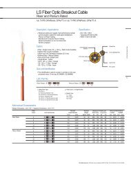
7.00 Accessories for <strong>EHV</strong> <strong>Cable</strong> <strong>System</strong>s<br />
<strong>LS</strong> <strong>Cable</strong> has developed and manufactured a wide range of terminations and joints for Extra High<br />
Voltage(<strong>EHV</strong>) cable system since 1983. Prefabricated terminations and tape molded joints are installed for<br />
154kV cable system in domestic market. A new advanced accessories, which is called prefabricated and<br />
premolded joints, were developed and supplied to many countries in the world. <strong>Cable</strong> systems from 132kV<br />
up to 400kV has been certified through the type test by many international independent institutes<br />
(KEMA, CESI, KERI).<br />
Pre-qualification tests for 345kV and 400kV cable systems in accordance with latest IEC standard were carried<br />
out successfully by the KEMA and KERI.<br />
7.01 Outdoor Terminations for 66kV~110kV<br />
7.02 Outdoor Terminations for 132kV~275kV<br />
7.03 Outdoor Terminations for 345kV~500kV<br />
7.04 SF 6 Gas Insulated Terminations<br />
7.05 Oil-Immersed Terminations<br />
7.06 Pre-Moulded Joint(PMJ)<br />
7.07 Link Box<br />
7.08 Transition Joint<br />
7.09 Optical <strong>Cable</strong> & Joint<br />
Accessories for <strong>EHV</strong> <strong>Cable</strong> <strong>System</strong>s 37
7.01 Outdoor Terminations for 66kV~110kV<br />
38<br />
Porcelain(Polymer) Insulator<br />
Silicone Rubber Sleeve<br />
Supporting Insulator<br />
Accessories for <strong>EHV</strong> <strong>Cable</strong> <strong>System</strong>s<br />
Figure 1 Figure 2<br />
Polymer Insulator<br />
(with Stress Relief Dlevices)
The outdoor terminations for 66~110kV are classified on two types.<br />
One is based on silicone rubber sleeve(so called Pre-moulded type,<br />
Figure1). The other is based on silicone rubber housing(so called dry<br />
type, Figure2). Pre-moulded silicone rubber sleeve is designed to fit<br />
with controlled interference over the cable insulation and is able to<br />
follow the cable's diameter variations still guaranteeing under any<br />
service condition a sufficient positive pressure to control the electric<br />
field concentration. This uses elastic retention of silicone material itself.<br />
The termination is filled with an insulating compound up to a level<br />
where the electric field is substantially reduced. The termination base<br />
plate and the cable's metallic sheath are electrically insulated from the<br />
supporting structure by means of stand off insulators designed to withstand both mechanical and electrical stresses in<br />
services. Upon request of the customer, either porcelain or composite hollow insulator can be supplied. And the<br />
insulator can be supplied in brown or grey color. The maximum allowable cable conductor size is 3000mm 2 (6000kcmil).<br />
The latter uses pre-moulded silicone housing with built in sleeve. They completely free from any Liquid insulating<br />
materials. The high electrical field area of the termination surface covered with skirts.<br />
The housing is whole preformed and can be supplied in grey color. This has advantage like easier installation. The<br />
maximum allowable cable conductor size 3000mm 2 (6000kcmil). The main insulation components are fully examined<br />
and tested in the factory.<br />
Rating & Dimension(Based on pre-moulded type)<br />
Max. Voltage<br />
BIL<br />
Max. Height Max. Weight<br />
Max. Creepage<br />
Distance<br />
kV<br />
kV<br />
mm kg mm<br />
72.5 325 1000 100 2500<br />
123 550 1500 200 4300<br />
Rating & Dimension(Based on Dry type)<br />
Max. Voltage BIL<br />
Max. Height Max. Weight<br />
Max. Creepage<br />
Distance<br />
kV<br />
kV<br />
mm kg mm<br />
72.5 325 980 100 2500<br />
123 550 1350 200 4300<br />
Selection of insulators with respect to polluted conditions<br />
(Based on IEC60815)<br />
Pollution<br />
Min. Norminal<br />
(Light) (Medium) (Heavy) (Very Heavy)<br />
Specific Creepage<br />
Distance<br />
16mm/kV 20mm/kV 25mm/kV 31mm/kV<br />
Accessories for <strong>EHV</strong> <strong>Cable</strong> <strong>System</strong>s 39
7.02 Outdoor Terminations for 132kV~275kV<br />
40<br />
Porcelain(Polymer) Insulator<br />
Epoxy housing<br />
Stress Relief Cone<br />
Accessories for <strong>EHV</strong> <strong>Cable</strong> <strong>System</strong>s<br />
Figure 3 Figure 4<br />
Porcelain(Polymer) Insulator<br />
Silicone Rubber Sleeve<br />
Supporting Insulator Supporting Insulator
The outdoor termination for 132~275kV is classified into two types.<br />
One is based on the EPR-based rubber stress relief cone with an epoxy<br />
housing(so called pre-fabricated type, figure3). The other is based on<br />
the silicone rubber sleeve(so called pre-molded type, figure4).<br />
The former uses mechanical devices to maintain the interface pressure.<br />
The latter uses elastic retention of silicone material itself. Pre-moulded<br />
silicone rubber sleeve is designed to fit with controlled interference<br />
over the cable insulation and is able to follow the cable's diameter<br />
variations still guaranteeing under any service condition a sufficient<br />
positive pressure to control the electric field concentration.<br />
The termination base plate and the cable's metallic sheath are<br />
electrically insulated from the supporting structure by means of stand off insulators designed to withstand both<br />
mechanical and electrical stresses in services. Upon request of the customer, either porcelain or composite hollow<br />
insulator can be supplied. And the insulator can be supplied in brown or grey colour. In addition upon request of the<br />
customer, arcing horn and shield ring can be supplied. The termination is filled with an insulating compound up to a<br />
level where the electric field is substantially reduced. The main insulation components are fully examined and tested in<br />
the factory. The maximum allowable cable conductor size is 3000mm 2 (6000kcmil).<br />
Rating & Dimension(Based on pre-moulded type)<br />
Max. Voltage BIL<br />
Max. Height Max. Weight<br />
Max. Creepage<br />
Distance<br />
kV<br />
kV<br />
mm kg mm<br />
145 650 2410 700 5000<br />
170 750 2410 800 6000<br />
275 1050 3500 900 8400<br />
Selection of insulators with respect to polluted conditions<br />
(Based on IEC60815)<br />
Pollution<br />
Min. Norminal<br />
(Light) (Medium) (Heavy) (Very Heavy)<br />
Specific Creepage<br />
Distance<br />
16mm/kV 20mm/kV 25mm/kV 31mm/kV<br />
Accessories for <strong>EHV</strong> <strong>Cable</strong> <strong>System</strong>s 41
7.03 Outdoor Terminations for 345kV~500kV<br />
42<br />
Porcelain(Polymer) Insulator Porcelain(Polymer) Insulator<br />
Condenser Cone<br />
Epoxy housing<br />
Stress Relief Cone<br />
Supporting Insulator<br />
Accessories for <strong>EHV</strong> <strong>Cable</strong> <strong>System</strong>s<br />
Figure 5 Figure 6<br />
Silicone Rubber Sleeve
The outdoor termination for 345~500kV is classified into two types.<br />
One is based on the EPR-based stress relief cone with the epoxy<br />
housing and the oil-impregnated cylindrical capacitor cone is added to<br />
secure the uniform longitudinal voltage distribution all along the<br />
termination(so called condenser cone type, figure 5). The other is based<br />
on silicone rubber sleeve(so called pre-molded type, figure 6).<br />
The former uses mechanical devices to maintain the interface pressure<br />
and the latter uses elastic retention of silicone material itself.<br />
Pre-moulded silicone rubber sleeve is designed to fit with controlled<br />
interference over the cable insulation and is able to follow the cable's<br />
diameter variations still guaranteeing under any service condition a<br />
sufficient positive pressure to control the electric field concentration.<br />
The termination base plate and the cable's metallic sheath are electrically insulated from the supporting structure by<br />
means of stand off insulators designed to withstand both mechanical and electrical stresses in services. Upon request of<br />
the customer, either porcelain or composite hollow insulator can be supplied. And the insulator can be supplied in<br />
brown or grey colour. In addition upon request of the customer, arcing horn and shield ring can be supplied. The<br />
termination is filled with an insulating compound up to a level where the electric field is substantially reduced. The main<br />
insulation components are fully examined and tested in the factory. The maximum allowable cable conductor size is<br />
3000mm 2 (6000kcmil).<br />
Rating & Dimension(Based on pre-moulded type)<br />
Max. Voltage BIL<br />
Max. Height Max. Weight<br />
Max. Creepage<br />
Distance<br />
kV<br />
kV<br />
mm kg mm<br />
362 1175 4300 1700 13000<br />
420 1425 4300 2000 14500<br />
550 1550 5000 2500 20000<br />
Selection of insulators with respect to polluted conditions<br />
(Based on IEC60815)<br />
Pollution<br />
Min. Norminal<br />
(Light) (Medium) (Heavy) (Very Heavy)<br />
Specific Creepage<br />
Distance<br />
16mm/kV 20mm/kV 25mm/kV 31mm/kV<br />
Accessories for <strong>EHV</strong> <strong>Cable</strong> <strong>System</strong>s 43
7.04 SF 6 Gas Insulated Terminations<br />
44<br />
Accessories for <strong>EHV</strong> <strong>Cable</strong> <strong>System</strong>s<br />
For Dry Dimension<br />
< Dry Type ><br />
For Fluid Filled Dimension<br />
Adapter<br />
(for extention)<br />
Epoxy insulator Epoxy insulator<br />
Stress relief cone Stress relief cone<br />
Spring Unit Spring Unit
The construction of SF6 gas insulated terminations is based on the<br />
EPR(Ethylene-Propylene Rubber)-based stress relief cone and the epoxy<br />
resin housing. They are mechanical devices to maintain the interface<br />
pressure. Stress relief cone and mechanical devices are designed to fit<br />
with controlled interference over the cable insulation and is able to<br />
follow the cable's diameter variations still guaranteeing under any<br />
service condition a sufficient positive pressure to control the electric<br />
field concentration.<br />
They also use epoxy insulating plate to isolate between cable sheath<br />
and GIS chamber. The SVLs(Sheath Voltage Limiter) can be installed to<br />
protect epoxy insulating plate from switching impulse. Upon request<br />
of the customer, we can supply three type of leading conductors. That is normal type, blind-ended type, plug-in type.<br />
Design and scope of delivery are fully complying with IEC60859 , IEC62271-209 and possibly adjusted to various needs<br />
of customers. The main insulation components are fully examined and tested in the factory. They are currently available<br />
at the voltage range up to 500kV and the maximum allowable cable conductor size is 3000mm 2 (6000kcmil).<br />
Rating & Dimension(Based on IEC 60859)<br />
Max. Voltage<br />
kV<br />
BIL<br />
kV<br />
Max. Height<br />
Dimension of<br />
base plate<br />
Max. weight<br />
mm mm kg<br />
72.5 325 583 270 120<br />
123 550 470 320 130<br />
145 650 470 320 150<br />
170 750 470 320 170<br />
245 1050 620 582 280<br />
420 1425 960 640 500<br />
550 1550 960 640 600<br />
Accessories for <strong>EHV</strong> <strong>Cable</strong> <strong>System</strong>s 45
7.05 Oil-Immersed Terminations<br />
Epoxy insulator Epoxy insulator<br />
46<br />
Stress relief cone Stress relief cone<br />
Spring Unit Spring Unit<br />
Material Casing Material Casing<br />
Accessories for <strong>EHV</strong> <strong>Cable</strong> <strong>System</strong>s<br />
Below 220kV Above 345kV
The construction of oil immersed terminations is based on the<br />
EPR(Ethylene-Propylene Rubber)- based stress relief cone and the<br />
epoxy housing. This is similar to gas insulated sealing end. But they use<br />
shield ring with insulating paper or epoxy insulated layer to prevent<br />
flashover in transformer. They are mechanical devices to maintain the<br />
interface pressure. Stress relief cone and mechanical devices are<br />
designed to fit with controlled interference over the cable insulation<br />
and is able to follow the cable's diameter variations still guaranteeing<br />
under any service condition a sufficient positive pressure to control the<br />
electric field concentration. The main insulation components are fully<br />
examined and tested in the factory. Dimensions of base paste are<br />
complying with various needs of customers. They are currently available at the voltage range up to 500kV and the<br />
maximum allowable size is 3000mm 2 (6000kcmil).<br />
Rating & Dimension<br />
Max. Voltage<br />
kV<br />
BIL<br />
kV<br />
Max. Height<br />
Dimension of<br />
base plate<br />
Max. weight<br />
mm mm kg<br />
72.5 325 686 270 130<br />
123 550 841 320 140<br />
145 650 841 320 180<br />
170 750 841 320 180<br />
245 1050 1040 582 280<br />
420 1425 1440 640 520<br />
550 1550 1440 640 620<br />
Accessories for <strong>EHV</strong> <strong>Cable</strong> <strong>System</strong>s 47
7.06 Pre-Moulded Joint(PMJ)<br />
Metalic Casing Type<br />
Coffin Box Type<br />
48 Accessories for <strong>EHV</strong> <strong>Cable</strong> <strong>System</strong>s<br />
Ferrule Joint Sleeve Metal Casing<br />
Coffin Box Ferrule Joint Sleeve
Metalic Casing &<br />
Coffin Box Type<br />
Coffin Box Ferrule Joint Sleeve Metal Casing<br />
The single piece pre-moulded type rubber joint is based on silicone insulation embedded with two semi-conductive<br />
stress relief cones and one high voltage electrode. Without any mechanical devices, the interface pressure is safely<br />
maintained with elastic retention of material itself. Semi-conductive stress relief cones and electrode are designed to fit<br />
with controlled interference over the cable insulation and is able to follow the cable' s diameter variations still<br />
guaranteeing under any service condition a sufficient positive pressure to control the electric field concentration. Upon<br />
request of the customer, outer casing is designed(metalic casing, coffin box, and metalic casing with coffin box). They<br />
use filling compound in outer casing. In case of sheath sectionalizing joint, we use insulating plate made of epoxy or<br />
FRP to disconnect between cable sheathes. The main insulation components and outer casing components are factorymade<br />
and fully tested before delivering to the site. The cost-efficient and simplified design along with easy and fast<br />
installation meets the various needs of customers. Installation tools can be provided if requested by customers. They are<br />
currently available at the voltage range up to 500kV and the maximum allowable conductor size is<br />
3000mm 2 (6000kcmil).<br />
Rating & Dimension(Based on Coffin Box Type)<br />
Max. Voltage<br />
kV<br />
Max. Lenght<br />
mm<br />
Max. Outer Dia. Max. Weight<br />
mm mm<br />
72.5 2000 500 90<br />
123 2000 500 120<br />
145~170 2000 500 150<br />
245~300 2200 550 200<br />
362~420 2600 700 300<br />
550 2700 700 400<br />
Accessories for <strong>EHV</strong> <strong>Cable</strong> <strong>System</strong>s 49
7.07 Link Box<br />
50 Accessories for <strong>EHV</strong> <strong>Cable</strong> <strong>System</strong>s<br />
Buried Type : Link Box for cross bonding(3-1Way)<br />
Gantry Mounted Type : Link Box for Earthing(3-1Way)
Link Boxes are used at the end of cable termination to gain easy access to<br />
the cable metallic sheath and to limit the transient over-voltage induced<br />
on the metallic sheath by the lighting, switching operations and fault<br />
currents. Cross bonding(C.B.) link boxes allow metallic sheath to be<br />
transposed at cable joints with surge voltage suppression and reduction of<br />
circulation currents. Sheath voltage limiters(SVLs) in link box are the<br />
gapless ZnO arresters, which have the insulation resistance above 100M<br />
at test voltage so that the sheath insulation can be checked without<br />
disconnection SVLs.<br />
Standard Product Box Type<br />
Approx. Size<br />
Link Box for Earthing(1-1Way)<br />
Link Box for Earthing(3-1Way)<br />
Link Box with SVLs(3-1Way)<br />
Link Box for Cross-Bonding<br />
.(3-1Way)<br />
Link Box for Bonding & Earthing<br />
(3-1Way)<br />
Link Box for Earthing with SVL<br />
(3-1way)<br />
Gantry Mounted<br />
/ Buried<br />
Gantry Mounted<br />
/ Buried<br />
Gantry Mounted<br />
/ Buried<br />
Gantry Mounted<br />
/ Buried<br />
mm<br />
150X150<br />
200X200<br />
300X500<br />
350X600<br />
450X500<br />
500X550<br />
500X550<br />
550X600<br />
Bonding Lead Approx. Weight<br />
Single Core<br />
Single Core<br />
Single Core<br />
Concentric<br />
Buried 700X500 Concentric 80<br />
Buried 700X500 Concentric 50<br />
kg<br />
15<br />
30<br />
30<br />
50<br />
40<br />
70<br />
50<br />
80<br />
Accessories for <strong>EHV</strong> <strong>Cable</strong> <strong>System</strong>s 51
7.08 Transition Joint<br />
52 Accessories for <strong>EHV</strong> <strong>Cable</strong> <strong>System</strong>s<br />
Bell Mouth<br />
Epoxy Unit Spring Unit<br />
Ferrule Stress relief cone<br />
The transition joint connects between existing oil-filled cables and extruded dielectric cables. They comprise the stop joint with<br />
oil-impregnated paper insulation and epoxy bell mouth at side of oil-filled cables. They also comprise prefabricated type joint<br />
with stress relief cone based EPR(Ethylene-Propylene Rubber) and mechanical devices at side of extruded dielectric cables. They<br />
are designed to fit with controlled interference over the cable insulation and is able to follow the cable's diameter variations<br />
still guaranteeing under any service condition a sufficient positive pressure to control the electric field concentration. Each<br />
components fully examined and tested in the factory. They are currently available at the voltage range up to 300kV and the<br />
maximum allowable cable conductor size is 3000mm 2 (6000kcmil).<br />
Rating & Dimension<br />
Max. Voltage<br />
Max. Lenght<br />
Max. Outer Dia. Max. Weight<br />
kV<br />
mm<br />
mm mm<br />
145 1800 290 220<br />
170 1800 320 250<br />
245 2000 360 300
7.09 Optical <strong>Cable</strong> & Joint<br />
These type for power cable are very useful to measure distributed temperature. Especially optical cable located the sensing<br />
fiber to the cable core provides a better indication of conductor temperature. We can supply optical joint to connect optical<br />
fiber cable.<br />
Optical Fiber Joint Box<br />
<strong>Cable</strong> Embeded<br />
Optical <strong>Cable</strong><br />
Accessories for <strong>EHV</strong> <strong>Cable</strong> <strong>System</strong>s 53
54 Monitoring & Diagnosis <strong>System</strong><br />
8.00 Monitoring & Diagnosis <strong>System</strong><br />
8.01 Real Time Thermal Monitoring-Underground<br />
Power <strong>Cable</strong> <strong>System</strong><br />
8.02 On-Site PD Detection <strong>System</strong>
8.01 Real Time Thermal Monitoring-Underground<br />
Power <strong>Cable</strong> <strong>System</strong><br />
Real time thermal monitoring cooperated with DTS* system using optical fiber as the sensor provides high efficiency and reliability of<br />
power cable system.<br />
Dynamic Rating<br />
<strong>System</strong><br />
(Power cable)<br />
Personal Computer<br />
SCADA<br />
Dynamic Rating <strong>System</strong> Temperature Monitoring<br />
Under Ground <strong>Cable</strong> Thermal Modeling<br />
Thermal models and real-time temperature measurement<br />
can provide dynamic rating system. And this system allows<br />
qualification of actual cable capacity, cable conditions and<br />
environmental parameters critical to the stability and<br />
longevity of the cable system.<br />
Dynamic <strong>Cable</strong> Rating <strong>System</strong>s (R-TAS TM )<br />
Monitor<br />
<strong>Cable</strong> Temperature<br />
Joint Temperature<br />
Ambient Temperature<br />
<strong>System</strong> Load Current<br />
Process<br />
IEC 60287<br />
Real Time Algorithms<br />
Power <strong>Cable</strong> Thermal Model<br />
*Distributed Temperature Sensor : Supplied by Sensa, UK. For more information, refer to www.sensa.org<br />
Right : Sensor fiber<br />
embedded cable<br />
(under the sheath)<br />
Left : Sensor fiber<br />
attached cable<br />
These types of power cable are very useful to measure<br />
distributed temperature. Especially, the right cable, located<br />
the sensing fiber closer to the cable core, provides a better<br />
indication of conductor temperature.<br />
Output<br />
Conductor Temperature<br />
Circuit Rating Capability<br />
(Steady State & Emergency)<br />
Time to Over-Temperature<br />
Over Current Alarms<br />
Thermal/Loading History<br />
Monitoring & Diagnosis <strong>System</strong> 55
8.02 On-Site PD Detection <strong>System</strong><br />
56<br />
On-Site PD Detection <strong>System</strong><br />
On-Site PD Detection based on high frequency PD measurement can be a highly<br />
effective method to increase the reliability of XLPE power cable system not only as afterlaying<br />
test but also as on-site insulation diagnosis.<br />
Characteristics of On-Site PD Detection <strong>System</strong><br />
High sensitivity by tuning low noise frequency range<br />
<strong>System</strong> configuration without line-off<br />
Easy installation of PD sensor<br />
Pattern recognition by -q-n analysis<br />
PD localization using PD attenuation property<br />
Sensor Type<br />
HFCT<br />
Installation on Ground Wire or Cross-Bonding Wire of Joint<br />
Measuring Frequency Range : More than 2MHz<br />
(Depends on the type of HFCT)<br />
Outer Type Capacitive Sensor<br />
Installation on Outer Sheath of Joint<br />
(Applicable only for Insulating Joint)<br />
Measuring Frequency Range : 1MHz ~ 50MHz<br />
Inner Type Capacitive Sensor<br />
Installation on Semi-Conductive Layer in Joints<br />
Measuring Frequency Range : 2 ~ 20MHz<br />
Sensor<br />
Sensor
9.00 Appendix<br />
9.01 Type Test/Pre-Qualification Test Certificates<br />
9.02 ISO Certificates<br />
Appendix 57
9.01 Type Test/Pre-Qualification Test Certificates<br />
The reliability of XLPE cable systems are fully verified by internationally accredited independent laboratories, KEMA (Netherlands), CESI (Italy),<br />
Kinetrics (Canada) and KERI (Korea).<br />
Certificates for XLPE cable system over 230kV<br />
Year<br />
1999<br />
2001<br />
2002<br />
2003<br />
2004<br />
2006<br />
2007<br />
2008<br />
58<br />
Appendix<br />
Voltage Grade<br />
400kV, 1200mm 2<br />
230kV, 1200mm 2<br />
345kV, 2000mm 2<br />
345kV, 2000mm 2<br />
400kV, 1200mm 2<br />
345kV, 2500mm 2<br />
345kV, 2500mm 2<br />
400kV, 2500mm 2<br />
230kV 800SQ<br />
345kV 2500SQ<br />
345kV1500SQ<br />
380kV2500SQ<br />
345kV2500SQ<br />
Spec. Test Items<br />
Certificate Issued by Test<br />
IEC62067<br />
IEC62067<br />
IEC62067<br />
IEC62067<br />
IEC62067<br />
IEC62067<br />
IEC62067<br />
IEC62067<br />
<strong>Cable</strong>, PJ, GIS & Outdoor Termination<br />
<strong>Cable</strong>, PMJ, GIS & Outdoor Termination<br />
<strong>Cable</strong>, PJ, GIS & Outdoor Termination<br />
<strong>Cable</strong>, PJ, GIS & Outdoor Termination<br />
<strong>Cable</strong>, PJ, GIS & Outdoor Termination<br />
<strong>Cable</strong>, PJ, GIS & Outdoor Termination<br />
<strong>Cable</strong>, GIS & Outdoor Termination<br />
<strong>Cable</strong>, PMJ, GIS & Outdoor Termination<br />
<strong>Cable</strong>, GIS, Outdoor Termination<br />
<strong>Cable</strong>, PMJ, Outdoor Termination<br />
<strong>Cable</strong>, PMJ, Outdoor Termination<br />
<strong>Cable</strong>, GIS, Outdoor Termination<br />
<strong>Cable</strong>, GIS, PMJ, Outdoor Termination<br />
KEMA<br />
KEMA<br />
KERI(KEPCO)<br />
KERI(KEPCO)<br />
KEMA<br />
KEMA<br />
KEMA<br />
KEMA<br />
SGS<br />
KEMA<br />
KEMA<br />
KEMA<br />
KERI(KEPCO)<br />
Type Test<br />
Type Test<br />
Type Test<br />
PQ<br />
PQ<br />
Type Test<br />
PQ<br />
Type Test<br />
Type Test<br />
Type Test<br />
Type Test<br />
Type Test<br />
Type Test
9.02 ISO Certificates<br />
We do what it takes to earn quality certifications like ISO 14001, ISO 9001, and ISO/TS 16949 which sets standards for process control and<br />
manufacturing flow.<br />
Appendix 59
<strong>LS</strong> <strong>Cable</strong><br />
Korea’s foremost cable maker in both product list and service range,<br />
<strong>LS</strong> <strong>Cable</strong> has an integrated supply system from basic raw materials to<br />
ultranhigh voltage cables, optical fiber cables, system engineering and installation works.<br />
In non-cable sector as well, <strong>LS</strong> <strong>Cable</strong> flourishes as a top-rate supplier of information and<br />
communication networks, connectors, lead frames, industrial rubber, and aluminum products.<br />
Reputed for its outstanding technology and quality,<br />
<strong>LS</strong> <strong>Cable</strong> is at the service of customers within and oytside Korea.<br />
Armed with the world’s leading technology in electric power and optic fiber,<br />
it has been successful with four joint ventures in Malaysia and Vietnam.<br />
It has thus demonstrated leadership in establishing a global<br />
network in the domains of electric power, other energy and information.
10.00 Global Network
www.lgce.net<br />
Energieweg 19<br />
3281 NH Numansdorp<br />
Tel: +31(0)186-659510<br />
Fax: +31(0)186-659511