

DB15 VGA Connector Schematic and Pinout ... - Sound Services
DB15 VGA Connector Schematic and Pinout ... - Sound Services
DB15 VGA Connector Schematic and Pinout ... - Sound Services

Create successful ePaper yourself
Turn your PDF publications into a flip-book with our unique Google optimized e-Paper software.
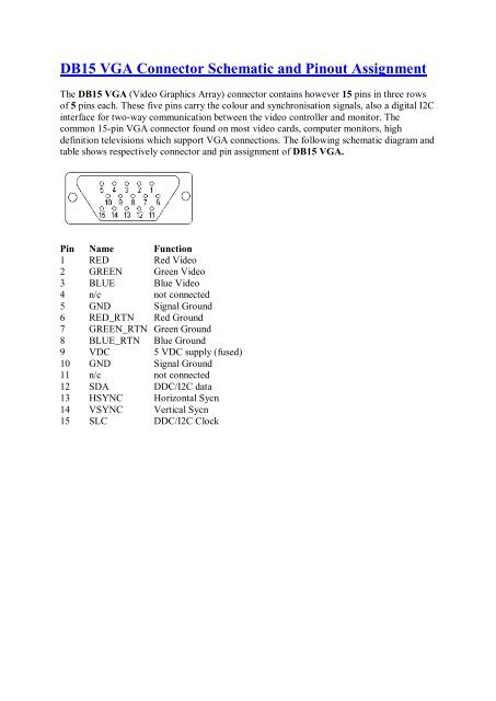
<strong>DB15</strong> <strong>VGA</strong> <strong>Connector</strong> <strong>Schematic</strong> <strong>and</strong> <strong>Pinout</strong> Assignment<br />
The <strong>DB15</strong> <strong>VGA</strong> (Video Graphics Array) connector contains however 15 pins in three rows<br />
of 5 pins each. These five pins carry the colour <strong>and</strong> synchronisation signals, also a digital I2C<br />
interface for two-way communication between the video controller <strong>and</strong> monitor. The<br />
common 15-pin <strong>VGA</strong> connector found on most video cards, computer monitors, high<br />
definition televisions which support <strong>VGA</strong> connections. The following schematic diagram <strong>and</strong><br />
table shows respectively connector <strong>and</strong> pin assignment of <strong>DB15</strong> <strong>VGA</strong>.<br />
Pin Name Function<br />
1<br />
2<br />
3<br />
4<br />
5<br />
6<br />
7<br />
8<br />
9<br />
10<br />
11<br />
12<br />
13<br />
14<br />
15<br />
RED<br />
GREEN<br />
BLUE<br />
n/c<br />
GND<br />
RED_RTN<br />
GREEN_RTN<br />
BLUE_RTN<br />
VDC<br />
GND<br />
n/c<br />
SDA<br />
HSYNC<br />
VSYNC<br />
SLC<br />
Red Video<br />
Green Video<br />
Blue Video<br />
not connected<br />
Signal Ground<br />
Red Ground<br />
Green Ground<br />
Blue Ground<br />
5 VDC supply (fused)<br />
Signal Ground<br />
not connected<br />
DDC/I2C data<br />
Horizontal Sycn<br />
Vertical Sycn<br />
DDC/I2C Clock
Nearly all modern PC graphics cards use the same 15 pin <strong>VGA</strong> connector that the original IBM <strong>VGA</strong><br />
card used. <strong>VGA</strong>=Video Graphics adapter or Video Graphics Array.<br />
<strong>VGA</strong> connectors<br />
There are at least four versions of the <strong>VGA</strong> connector, which are the three-row 15 pin DE-15<br />
(also called mini sub D15) in original <strong>and</strong> DDC2 pinouts, a less featureful <strong>and</strong> far less<br />
common 9-pin <strong>VGA</strong>, <strong>and</strong> a Mini-<strong>VGA</strong> used for laptops. The image <strong>and</strong> below table are the<br />
newer 15-pin <strong>VGA</strong> VESA DDC2 connector pinout.<br />
<strong>VGA</strong> connector pinout:<br />
Pin Name Dir Description<br />
1 RED Red Video (75 ohm, 0.7 V p-p)<br />
2 GREEN Green Video (75 ohm, 0.7 V p-p)<br />
3 BLUE Blue Video (75 ohm, 0.7 V p-p)<br />
4 ID2 Monitor ID Bit 2<br />
5 GND Ground<br />
6 RGND Red Ground<br />
7 GGND Green Ground<br />
8 BGND Blue Ground<br />
9 KEY - Key (No pin)<br />
10 SGND Sync Ground<br />
11 ID0 Monitor ID Bit 0<br />
12 ID1 or SDA Monitor ID Bit 1<br />
13 HSYNC or CSYNC Horizontal Sync (or Composite Sync)<br />
14 VSYNC Vertical Sync<br />
15 ID3 or SCL Monitor ID Bit 3<br />
Note: Direction is Computer relative Monitor. All <strong>VGA</strong> pinout signals except R, G, B are TTL level<br />
signals.<br />
<strong>VGA</strong> pinout : monitor ID detection pin assignments
4 11 12<br />
ID2 ID0 ID1<br />
n/c n/c n/c no monitor<br />
n/c n/c GND Mono monitor which does not support 1024x768<br />
n/c GND n/c Color monitor which does not support 1024x768<br />
GND GND n/c Color monitor which supports 1024x768<br />
GND means connected to ground<br />
n/c means that the pin is not connected anywhere<br />
This monitor type detection is becoming more <strong>and</strong> more obsolete nowadays. New <strong>VGA</strong> plug<strong>and</strong>-play<br />
monitors communicate with the computer according to VESA DDC st<strong>and</strong>ard.<br />
<strong>VGA</strong> VESA DDC<br />
VESA Display Data Channel is a method for integrating digital interface to <strong>VGA</strong> connector<br />
so as to enable the monitor <strong>and</strong> graphics card to communicate. There are two different levels<br />
of DDC: DDC1 <strong>and</strong> DDC2.<br />
<strong>VGA</strong> DDC1 pinout details<br />
DDC1 allows the monitor to tell its parameters to the computer. The following <strong>VGA</strong> card<br />
connector pins have to be changed to allow DDC1 functions:<br />
<strong>VGA</strong> pin new function<br />
9 Optional +5V output from graphics card<br />
12 Data from display<br />
14 St<strong>and</strong>ard vertical sync signal which works also as data clock<br />
15 Monitor ID3<br />
When the <strong>VGA</strong> graphics card detects data on data-line it starts to read the data coming from<br />
the monitor synchronous to vertical sync pulse. Vertical sync pulse frequency can be<br />
increased up to 25 KHz for the time of the data transfer if a DDC1 compliant monitor is<br />
found (be sure not to send those high frequencies to non DDC1 monitors!).<br />
<strong>VGA</strong> DDC2 pinout details<br />
DDC2 allows bidirectional communication: monitor can tell its parameters <strong>and</strong> the computer<br />
can adjust monitor settings. The bidirectional data bus is a synchronous data bus similar to<br />
Access Bus <strong>and</strong> is based on I2C technology. The following pins on <strong>VGA</strong> pinout have to be<br />
changed to enable DDC2 to work:<br />
<strong>VGA</strong> pin new function<br />
9 Optional +5V output from graphics card<br />
12 Bidirectional data line (SDA)<br />
15 Data clock (SCLK)<br />
The signals in the data bus are st<strong>and</strong>ard I2C signals. The computer provides 15 kohm pullup<br />
for the SDA <strong>and</strong> SCLK lines. Monitor must provide 47 kohm pull-up on SCLK line.