1988 - Spinoff - NASA
1988 - Spinoff - NASA
1988 - Spinoff - NASA

You also want an ePaper? Increase the reach of your titles
YUMPU automatically turns print PDFs into web optimized ePapers that Google loves.
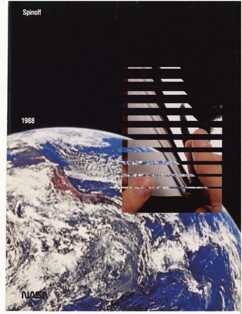
<strong>Spinoff</strong>
<strong>Spinoff</strong><br />
For sale by the<br />
Superintendent of Documents,<br />
U.S. Government Printing Office<br />
Washington, D.C. 20402<br />
National Aeronautics and<br />
Space Administration<br />
Office of Commercial Programs<br />
Technology Utilization Division<br />
by James J. Haggerty<br />
August <strong>1988</strong>
i Foreword<br />
7 he year <strong>1988</strong>, the 30th anniversary of We have a renewed mandate from the<br />
the National Aeronautics and Space President, whose National Space Policy, is-<br />
! Administration, marks the start of a sued in <strong>1988</strong>, reaflirmed the basic goal of<br />
new era of space development and explora- United States leadership in space. What<br />
tion. In the flight hiatus since the Challenger <strong>NASA</strong> and the Nation need now is a new<br />
accident, the Nation has undeniably lost national commitment of will and resources to<br />
ground in global space competition. How- attain that goal. That commitment must be<br />
ever, we have never lost sight of the goal of based on the realization that our economic<br />
space leadership, nor have we lost the ca- growth and prosperity, our industrial innova-<br />
pability to attain that goal. tion and productivity, our national security,<br />
<strong>NASA</strong>'s employees and contractors retain and our prestige and national pride are all<br />
the imagination that opens up new horizons, closely linked to our future in space.<br />
the management expertise to organize and Given the full support of the American<br />
I<br />
I guide challenging programs, and the tech- people and resources we need to complete<br />
nical skills to translate vision into reality. the task, I am confident that the U.S. can<br />
Thirty years of working to advance technol- and will lead spacefaring nations into a new<br />
ogy have given us a great bank of know-how era of progress and prosperity in the 2 1st<br />
to draw upon. <strong>NASA</strong> also has the tools, fachties<br />
and human assets required to seek<br />
and demonstrate excellence in space.<br />
We have established a broad and progressive<br />
space program that will expand space<br />
infrastructure and thus enable pursuit of a<br />
wider range of opportunities. Our program<br />
century.<br />
also will improve our space transportation James C. Fletcher<br />
system, bring about far-reaching advance- Administrator<br />
ments in space science, pursue the many<br />
practical benefits space offers, and build a<br />
technological foundation for the new <strong>NASA</strong><br />
National Aeronautics and Space Administration<br />
i<br />
goal of extending the human presence beyond<br />
Earth orbit.
Introduction<br />
+<br />
U.S . competitiveness is a subject The Congress has charged <strong>NASA</strong> with the<br />
that is getting a great deal task of stimulating the widest possible use of<br />
of attention from our na- this valuable resource in the national interest.<br />
tional leadership. America's ability to com- <strong>NASA</strong> seeks to meet that responsibility<br />
pete effectively in the international market- through its Technology Utilization Program,<br />
place is central to our current and future whose aim is to broaden and accelerate the<br />
national economy. The key to competitive- technology transfer process and to gain<br />
ness is technology, which-by one dehi- thereby a substantial dividend on the nation-is<br />
"that body of knowledge and a- tional investment in aerospace research in the<br />
pability required to bring a product to the form of new products, new businesses and<br />
marketplace. "<br />
new jobs. The prom is designed to serve<br />
The U.S. long dominated world technol- as a channel linking <strong>NASA</strong> technology<br />
ogy but in recent years we have been strongly with those who might be able to apply it<br />
challenged by foreign nations, who have in- productively.<br />
vested in years of intense research and devel- This publication is intended to heighten<br />
opment to upgrade their own technological awareness among potential users of the<br />
capabilities. Our response, if we are to main- technology available for transfer and the<br />
tain competitiveness, must be to continue economic and social benefit that might be<br />
development and application of advanced realized by secondary applications.<br />
technology to create superior products and <strong>Spinoff</strong> <strong>1988</strong> is organized in three sections:<br />
services for the world market.<br />
Section 1 outlines <strong>NASA</strong>'s mainline effort,<br />
<strong>NASA</strong> research programs, therefore, are the major programs that generate new techdoubly<br />
important.<br />
nology and therefore replenish and expand<br />
First, they represent a leading source of the bank of knowledge available for transfer.<br />
new technology, because aerospace programs Section 2, the main feature of this volare,<br />
by their challenging nature, extraordi- ume, contains a representative sampling of<br />
narily demanding of technological input and spinoff products that resulted from secondary<br />
the innovations they generate are exception- application of technology originally develally<br />
diverse. Because it is readily transferable, oped to meet mainline goals.<br />
the technology being developed today pro- Section 3 describes the various mechavides<br />
a wellspring of know-how for new nisms <strong>NASA</strong> employs to stimulate technolapplications<br />
tomorrow.<br />
ogy transfer and lists, in an appendix, contact<br />
Secondly, <strong>NASA</strong> programs of the past sources for further information about the<br />
three decades have created a vast storehouse<br />
of already-developed technology that is available<br />
now for use by industry in aeating<br />
new products and processes. It is a natural<br />
resource that can be put to work to enhance<br />
national productivity and competitiveness.<br />
Its importance is underlined by the fact that<br />
Technology Utilization Program.<br />
more than 30,000 secondary applications /,am= T. Rose<br />
of this technology-spinoffs-have emerged<br />
to the benefit of the nation's lifestyle and Assistant Administrator for Cmmrcial Programs<br />
economy.<br />
National Aeronautics and Space Administration
Introduction<br />
Aerospace Aims<br />
Space Operations: The Next Decade 8<br />
Flight Plan for Tomorrow 20<br />
Exploring the Cosmos 30<br />
Commercial Use of Space 42<br />
Technology Twice Used<br />
Prologue<br />
spin off^ in:<br />
Health and Medicine<br />
Consumer/Home/Recreation<br />
Energy<br />
Environment<br />
Public Safety<br />
Transportation<br />
Manufacturing Technology<br />
Technology Utilization<br />
Recycling Technology
Aerospace Aims<br />
An illustrated summary of <strong>NASA</strong>'s major<br />
aeronautical and space programs, their<br />
goals and directions, their contributions<br />
to American scientific and technological<br />
growth, and their potential for practical<br />
benefits in new products and processes
Space Operations: The Next Decade<br />
<strong>NASA</strong>'s "new beginning"<br />
agenda features<br />
development of the Space<br />
Station Freedom in<br />
international partnership<br />
and steps toward expanding<br />
human presence beyond<br />
Earth orbital space<br />
8 Space 0pcraton.c The New Decade<br />
0<br />
n February 11, <strong>1988</strong>, President Reagan<br />
announced a revised national policy<br />
to guide U.S. space activities into<br />
the 2 1st century. Its three major components<br />
include:<br />
Establishing a long range goal to expand<br />
human presence and activity beyond Earth<br />
orbit;<br />
Creating opportunities for U.S. commerce<br />
in space; and<br />
Continuing the national commitment to a<br />
permanently manned Space Station.<br />
As Space Shuttle operations resume and<br />
<strong>NASA</strong> commences its fourth decade of space<br />
research and technology development, these<br />
aims-along with a vigorous space science<br />
effort-constitute the framework of <strong>NASA</strong>'s<br />
space program for the remaining years of the<br />
20th century.<br />
The Space Shuttle begins life anew a<br />
much improved system whose role in space<br />
operations will undergo a change of emphasis.<br />
For its first 24 flights, the Shuttle was<br />
largely a payload delivery system. It will<br />
continue to deliver free-flying payloads and<br />
the Spacelab orbiting workshop, but much<br />
of the commercial workload will be transferred<br />
to expendable launch vehicles.<br />
Planned Shuttle operations will take<br />
greater advantage of the system's versatility<br />
in such missions as retrieval of orbiting<br />
spaceaafi for repair, refurbishment and reuse;<br />
on-orbit servicing of long duration satellites<br />
and observatories such as the Hubble<br />
Space Telescope; serving as an orbital platform<br />
for investigations where human direction<br />
of the research is essential or benefi&,<br />
and conducting tests and evaluations of<br />
Space Station-related technologies. In the<br />
mid-19901s, it will become a combined delivery<br />
vehicle and construction base for assembly<br />
of the U.S./intemational Space Station<br />
Freedom and the station's link with<br />
Earth for resupply and aew rotation.<br />
The Shuttle reenters service a changed<br />
system. In addition to the redesigned Solid<br />
Rocket Boosters, Shuttle Orbiters Dkcwety,<br />
Atlantis, and Columbia have undergone, or<br />
are undergoing, some 30 modifications-for<br />
example, changes in the Orbiter's main en-<br />
gines, attitude control engines, landing gear,<br />
brakes, ancillary power units and the critical<br />
thermal protection system, plus the addition<br />
of a aew escape system. Shuttle flight rate<br />
will build up gradually, from 7-8 missions in<br />
1989, to 10 in 1990, to better than one a<br />
month when the as yet unnamed fourth Or-<br />
biter joins the fleet in 1992.<br />
The new directive to plan for human<br />
space activities beyond Earth orbit will in-<br />
volve earlier consideration of design factors<br />
related to use of the Space Station as a stag-<br />
ing base for exploration of the solar system.<br />
It does not change the immediate focus of<br />
the program: to establish a permanently<br />
manned research complex in low Earth orbit,<br />
a facility for scientific observation of Earth<br />
and the cosmos; for development of new<br />
technologies; and for research in life sciences<br />
and materials processing under conditions of<br />
near-zero gravity; and for realization of the<br />
commercial potential of space.<br />
A new and important activity beginning<br />
in Fiscal Year 1989 is Project Pathfinder, es-<br />
tablished by a Presidential directive that<br />
accompanied the space policy declaration.<br />
Amplified in later pages of this chapter,<br />
Pathfinder is a research and technology<br />
development effort intended to "provide a<br />
base for wise decisions on long term goals<br />
and missions," such as the widely discussed<br />
lunar outpost and manned expedition to<br />
Mars. A
The crew of STS-26: mission<br />
commander Frederick H. (Rick)<br />
Hauck (right front); pilot Richard<br />
0. Covey (left front); standing,<br />
left to right, mission specialists<br />
David C. Hilrners. Georae D. I (Pinky) Nelson and ~ ohn M.<br />
(Mike) Lounge.<br />
Symbol of a new begirlning: The<br />
Orbiter Discovery being rolled to<br />
the launch pad for Space Shuttle<br />
flight STS-26.<br />
Space Operationc The New Decade 9
Space Suit<br />
10 Space Operations: The New Decade<br />
hen the Space Sta-<br />
tion Freedom be-<br />
comes operational,<br />
extravehicular activity (EVA)<br />
is expected to become almost<br />
routine and on each EVA as-<br />
tronauts will work outside<br />
the station for long periods.<br />
To provide astronaut protec-<br />
tion from radiation,<br />
miaometeoroids and space<br />
debris yet allow adequate<br />
mobility and range of mo-<br />
tion for the wide variety of<br />
EVA tasks anticipated,<br />
<strong>NASA</strong> is developing an ad-<br />
, vanced space suit intended<br />
for EVA periods up to eight<br />
i In January <strong>1988</strong>, <strong>NASA</strong><br />
began evaluating two experimental<br />
prototypes of EVA<br />
suits being developed by<br />
Ames Research Center and<br />
Johnson Space Center, each<br />
employing a different design<br />
approach.<br />
Shown undergoing test in<br />
a water tank is Ames' X-5,<br />
I worn by space suit designer<br />
Herbert C. "Vic" Vykukal<br />
of the center's Aerospace<br />
Human Factors Research Di-<br />
vision. The AX-5 is an "all-<br />
hard" suit, made of alumi-<br />
num and stainless steel with<br />
no "soft" (fabric) parts.<br />
Miao Craft, Inc. is Ames'<br />
principal contractor.<br />
Johnson Space Center<br />
USC) is taking a design ap-<br />
proach based on the philoso-<br />
phy that soft parts enhance<br />
wearer comfort and should<br />
be employed to the extent<br />
possible. Its ZPS Mark 3<br />
suit has both hard and soft<br />
elements.<br />
The "ZPS" stands for<br />
"zero prebreathing suit. "<br />
Both suits are designed to<br />
eliminate the existing re-<br />
quirement, for Shuttle-based<br />
EVA, that astronauts<br />
prebreathe pure oxygen to<br />
eliminate nitrogen from<br />
body tissues before begin-<br />
ning EVA. Both suits, there-<br />
fore, are designed to operate<br />
at substantially higher pres-<br />
sures than the Shuttle suit,<br />
which necessitates use of<br />
some hard parts. Both suits<br />
are intended to provide<br />
greater mobility than the<br />
Shuttle suit offers with more<br />
comfort, despite the design<br />
constraints imposed by the<br />
higher pressure. <strong>NASA</strong> will<br />
select one suit or the other,<br />
or possibly a new hybrid de-<br />
sign that combines features<br />
of both, as the standard suit<br />
for Space Station or Space<br />
Shuttle EVA in the 1990s. A
Orbital Maneuvering Vehicle<br />
T<br />
he artist's concept<br />
shows a Shuttle deployed<br />
Orbital Maneuvering<br />
Vehicle (OW) retrieving<br />
an orbiting payload<br />
for return to the Shuttle Orbiter.<br />
The next planned addition<br />
to the space Transportation<br />
System, the OMV is<br />
being developed by TRW<br />
Inc.; Marshall Space Flight<br />
Center is project manager.<br />
The reusable OMV is a<br />
space tug intended to extend<br />
the reach of the Shuttle Or-<br />
biter by moving satellites<br />
and other objects to and<br />
from altitudes beyond the<br />
Orbiter's normal operating<br />
area of 150-300 miles above<br />
Earth's surface. It can, for<br />
example, propel a payload as<br />
far as 1,200 miles after<br />
deployment from the<br />
Orbiter--or it can retrieve a<br />
payload, deliver it to the Or-<br />
biter for repair, then return<br />
it to its operational orbit.<br />
Remotely-controlled by<br />
ground-based astronauts em-<br />
ploying television and other<br />
sensors to guide its move-<br />
ments, the OMV can handle<br />
routine on-orbit servicing,<br />
maintenance or payload<br />
changeout, and can be useful<br />
as a "Shuttle associate" in<br />
construction of large space<br />
structures. By use of modifi-<br />
cation kits, the versatile sys-<br />
tem can be configured to<br />
perform a wide variety of<br />
space tasks.<br />
No provision has been<br />
made for basing an O W at<br />
the initial baseline Space Station,<br />
but the OMV could<br />
evolve later into a station adjunct,<br />
performing such tasks<br />
as deployment of stationassembled<br />
satellites or positioning<br />
Shuttle-delivered<br />
resupply modules. The system<br />
is targeted for service in<br />
1993. r<br />
Space Operations: The New Decade I I
Space Station<br />
T<br />
he Space Station program<br />
moved ahead in<br />
the summer of <strong>1988</strong><br />
as <strong>NASA</strong> completed negotiations<br />
with its international<br />
parmers-Canada, the European<br />
space Agency (=A)<br />
and Japan-and cleared the<br />
way for formal signing of<br />
agreements in the fall.<br />
Shown above is the baseline<br />
Space Station with its<br />
four solar power modules at<br />
the ends of a 445-foot-long<br />
truss. In the center of the<br />
auss are the pressurized living<br />
and working areas, a<br />
U.S.-built habitation module<br />
12 Space Operatiom The New Decade<br />
and three laboratory modules<br />
to be provided by the U.S.,<br />
ESA and Japan.<br />
Linking the modules are<br />
pressurized "resource nodes,"<br />
which contain equipment to<br />
expand the available work-<br />
ing/living space. With the<br />
modules and nodes, the<br />
baseline Space Station will<br />
have 3 1,000 cubic feet of<br />
pressurized volume. The sta-<br />
tion design also includes pro-<br />
visions for mounting major<br />
experiments externally on the<br />
horizontal truss.<br />
Additional experiments<br />
will be accommodated by<br />
unmanned platforms operat-<br />
ing separately from the<br />
manned base in polar orbit,<br />
one to be built by the U.S.,<br />
the other by ESA. The U.S.<br />
platform is shown at top<br />
right; an important element<br />
of <strong>NASA</strong>'s earth observation<br />
program, it will carry a vari-<br />
ety of instruments for Earth<br />
biological, geological and<br />
oceanographic observations,<br />
atmosphere monitoring,<br />
observation of the Sun<br />
and plasma physics<br />
measurements.<br />
Designed to be serviced in<br />
orbit, it is being developed,<br />
under Goddard Space Flight<br />
Center management, by GE
Astro-Space Division with<br />
assistance h m team member<br />
TRW Inc. The GE/<br />
TRW team is also responsible<br />
for integration into the<br />
Space Station of the Fhght<br />
Telerobotic Servicer, a multiarmed<br />
robot that will help<br />
astronauts assemble the<br />
Space Station (above), later<br />
help maintain attached pay-<br />
k-<br />
%, 5'. ,<br />
i'h<br />
loah and assist in servicing<br />
s-.<br />
Another major component<br />
of the Space Station is the<br />
Mobile Servicing System<br />
(MSS) being developed by<br />
the Canadian government.<br />
Shown above, the robotic<br />
MSS operates h m the horizontal<br />
truss, positioned by a<br />
U.S.-provided mobile transporter,<br />
performing assembly,<br />
maintenance and servicing<br />
tasks. In the concept shown,<br />
the MSS manipulator arm is<br />
addug an experiment module<br />
to a auss-attached payload.<br />
. ' . .,' . . , . . .<br />
7' .<br />
.<br />
. .<br />
In addition to the GE/<br />
TRW contracts described,<br />
which are part of Work<br />
Package Three, <strong>NASA</strong><br />
awarded letter contracts in<br />
December 1987 to three<br />
other major contractors, each<br />
of which is supported<br />
by a number of team<br />
subcontractors.<br />
Under Work Package<br />
One, managed by Marshall<br />
Space Flight Center, k ing<br />
Aerospace Company will<br />
provide the U.S. laboratory<br />
and habitation modules, lo-<br />
gistics elements, resource<br />
node structures, airlock sys-<br />
tems, the environmental con-<br />
trol and life support system,<br />
audio and video systems,<br />
and associated software.<br />
Work Package Two,<br />
managed by Johnson Space<br />
Center, is being performed<br />
by a team headed by Mc-<br />
Domell Douglas Astronau-<br />
tics Company. It embraces<br />
the auss structure, the MSS<br />
transporter, airlocks, outfit-<br />
ting of the resource nodes,<br />
hardware and software for<br />
the data management sys-<br />
tem, the communications<br />
and tracking system, the<br />
guidance, navigation and<br />
control system, EVA sys-<br />
tems, the propulsion system,<br />
the thermal control system<br />
and amdated software.<br />
Rocketdyne Division of<br />
Rockwell International Cor-<br />
poration is handling Work<br />
Package Four under the<br />
management of Lewis<br />
Research Center. The<br />
Rocketdyne team will pro-<br />
vide the complete power sys-<br />
tem and associated software,<br />
including power generation,<br />
storage, management and<br />
distribution of electric<br />
power. Rocketdyne will also<br />
provide the electric power<br />
system for the U.S. polar<br />
orbiting platform.<br />
(Continued)<br />
Space Operationc Tbt New Decade 13
Space Station (Continued)<br />
The schedule for develop-<br />
ment and assembly of the<br />
Space Station Freedom is de-<br />
pendent upon funding levels,<br />
which had not been finally<br />
determined at publication<br />
time. A tentative schedule,<br />
based on the Administra-<br />
tion's budget plan, calls for<br />
the first launch of the assem-<br />
bly series in March 1995,<br />
when the Space Shuttle will<br />
deliver to an orbit 250 miles<br />
high an initial group of<br />
components for assembly in<br />
space.<br />
Over the following three<br />
years, there will be 19 addi-<br />
tional flights, 12 of them for<br />
delivery of manned base seg-<br />
ments, six for logistics and<br />
outfitting. The other flight,<br />
planned for late 1995, will<br />
deploy the U.S. polar orbit-<br />
ing platform.<br />
There will also be two<br />
flights of the European<br />
Ariane launch vehide, one in<br />
1997 to deploy the ESA po-<br />
lar platform, the other at the<br />
tail end of the assembly se-<br />
quence to deploy the ESA<br />
Man Tended Free Flyer, a<br />
miaogravity experiment fa-<br />
cility that will operate in an<br />
orbit compatible with that<br />
of Freedom.<br />
With delivery of the U.S.<br />
laboratory module on the<br />
fourth flight in late 1995,<br />
Freedom will have a capabil-<br />
14 Space Operations: The New Decade<br />
ity for man-tended opera-<br />
tions. Permanent occupancy<br />
will begin with the 1 lth<br />
flight late in 1996.<br />
The manned base of the<br />
Space Station Freedom in-<br />
dudes the four pressurized<br />
modules, three of them lab-<br />
oratories. The U.S. labora-<br />
tory module is a cylinder 45<br />
feet long and 14 feet in di-<br />
ameter. It will be pressur-<br />
ized-as will the other hu-<br />
man habitable modules-to<br />
Earth sea level equivalent<br />
pressure.<br />
At top is a Boeing Hunts-<br />
ville concept of the U.S. lab<br />
module. The astronaut in<br />
left photo is working in a<br />
commercial processing area<br />
that can be dosed off to pro-
tea proprietary worlc. ihe<br />
astronauts in the center are<br />
using a general work station,<br />
and at far right an astronaut<br />
is entering the module from<br />
a tunnel that connects with<br />
another module and with<br />
the visiting Shuttle Orbiter.<br />
ESA's Columbus labora-<br />
tory is of similar size, with<br />
an airlock for temporary ex-<br />
posure of experiments to the<br />
vacuum of space or for trans-<br />
fer of equipment to support<br />
external activities.<br />
Japan's JEM (Japanese<br />
Experiment Module) in-<br />
cludes a short pressurized<br />
segment to which a dome-<br />
shaped experiment logistics<br />
module can be attached, plus<br />
an "outdoors" exposed ex-<br />
periment facility for experi-<br />
ments where unpressurized<br />
conditions are preferred or<br />
essential.<br />
The U.S.-built habitation<br />
module, designed for a max-<br />
imum of eight astronauts,<br />
has everything needed for<br />
long duration occupancy, in-<br />
cluding facilities for eating,<br />
sleeping, relaxation, medical<br />
procedures and work activi-<br />
ties. At lefi is a Johnson<br />
Space Center USC) full scale<br />
modcup used for habitability<br />
studies. Above is a contractor<br />
concept of the module in<br />
which one astronaut (center<br />
photo), held in place by re-<br />
straining straps, sits at a<br />
work station while another<br />
prepares a meal in the mod-<br />
ule's galley (far left).<br />
Intended to operate for<br />
several decades, the Space<br />
Station can be expanded in<br />
both size and capability as<br />
<strong>NASA</strong>'s oved space pro-<br />
gram evolves. Among major<br />
enhancements envisioned are<br />
a servicing bay for mainte-<br />
nance and repair of un-<br />
manned satellites; another<br />
free-flying platform like the<br />
polar orbiters, this one op-<br />
erating in the same orbit as<br />
the Space Station; a solar dy-<br />
namic power system to aug-<br />
ment the electricity gener-<br />
ated by the solar power<br />
modules; and additional<br />
truss booms to provide ex-<br />
tensive accommodation for<br />
attached payloads. A<br />
Space Operatiow The New Decade 15
Project Pathfinder<br />
I<br />
he Presidential space<br />
policy announced in<br />
February <strong>1988</strong> di-<br />
rected that <strong>NASA</strong> pursue a<br />
long range goal "to establish<br />
human presence and activity<br />
beyond Earth orbit." The di-<br />
rective recognized, however,<br />
that an immediate decision<br />
on speufic goal, or set of<br />
goals, would be premature;<br />
intelligent goal selection<br />
among the alternatives being<br />
considered demands a<br />
broader science and technol-<br />
ogy base.<br />
16 Space Operatiom The New Decade<br />
Therefore, to lay a foun-<br />
dation for deciding advanced<br />
goals, the President's direc-<br />
tive created Project Path-<br />
finder, a major new program<br />
for research and development<br />
of "precursor" technologies<br />
that will enable a wide range<br />
of manned and unmanned<br />
missions beyond Earth orbit.<br />
Pathfinder will comple-<br />
ment and build upon the<br />
ongoing Civil Space Technol-<br />
ogy Initiative (CSTI). Where<br />
CSTI aims to develop tech-<br />
nologies related to space op-<br />
erations in low Earth orbit,<br />
Pathfinder will concentrate<br />
on emerging, innovative<br />
technologies that would<br />
make possible such lunar/in-<br />
terplanetary missions and ad-<br />
vanced robotic exploration of<br />
the solar system, a human-<br />
smffed outpost on the Moon,<br />
or a manned expedition to<br />
Mars.<br />
Project Pathfinder is orga-<br />
nized around four major<br />
thrusts: Exploration, Transfer<br />
Vehicles, Humans in Space,<br />
and Operations. Each thrust<br />
focuses on a set of key tech-<br />
nology elements to support<br />
critical mission capabilities.<br />
Examples of the Explora-<br />
tion thrust include develop-<br />
ment of the technologies<br />
needed for automated or as-
tronaut-driven roving vehi-<br />
cles that could operate on<br />
Mars or Earth's Moon;<br />
readily assembled surface<br />
power systems to support<br />
manned exploration of Mars<br />
or the Moon (left); and<br />
technologies for acquiring,<br />
analyzing and preserving sur-<br />
face and subsurface samples<br />
from the moon.<br />
The Transfer Vehicle<br />
thrust will provide the tech-<br />
nologies for transportation to<br />
and from the Moon, Mars<br />
and the other planets, and<br />
for transfer between different<br />
Earth orbits, for example,<br />
movement of people or cargo<br />
between low Earth orbit and<br />
geosynchronous orbit.<br />
Among examples of pro-<br />
gram elements are investiga-<br />
tion of both chemical and<br />
electrical propulsion systems<br />
and the technique of<br />
"aerobraking," in which the<br />
atmospheres of Earth or<br />
other solar system bodies are<br />
employed to decelerate a<br />
spacecraft in order to a&<br />
the requisite velocity for or-<br />
biting the body. Above is<br />
an artist's concept of an elec-<br />
trically-propelled cargo vehi-<br />
cle for use in supporting a<br />
manned Mars mission or<br />
robotic exploration of the<br />
outer planets.<br />
(Continued)<br />
Space Operationc The New Decade 17
Project Pathfinder (continued) r - w m<br />
Project Pathfinder's<br />
Humans in Space thrust has<br />
three major elements. One is<br />
directed toward providing a<br />
technology base that will al-<br />
low humans to operate for<br />
lengthy periods outside the<br />
protection of their pressur-<br />
ized habitats. It focuses on<br />
18 Space Operations: The New Decade<br />
two areas of technology:<br />
EVA suits (see page 10 ) and<br />
portable life support concepts<br />
and components.<br />
Another part of the<br />
Humans in Space effort in-<br />
volves development of tech-<br />
nologies to help accommo-<br />
date human physiological<br />
requirements and adaptive<br />
changes during long term<br />
confinement, exposure to un-<br />
natural gravitational condi-<br />
tions, and unaccustomed risk<br />
and stress. A third aspect of<br />
the program deals with tech-<br />
nologies for dosed-loop life<br />
support systems, intended to<br />
reduce the mass of consum-<br />
ables required and thus<br />
lower the cost of resupply for<br />
extended duration human<br />
space activities.<br />
The fourth Pathfinder<br />
thrust--Operations-<br />
embraces several program el-<br />
ements: among them auton-<br />
omous rende&ous and dock-<br />
ing for non-piloted space<br />
systems; technologies for a<br />
pilot plant capable of pro-<br />
cessing resources on the<br />
Moon or Mars, for example,<br />
exaacting oxygen for life<br />
support &om locally available<br />
materials, cryogenic fluid de-<br />
pot technologies to enable<br />
development of efficient sys-<br />
tems for servicing many<br />
types of space vehicles in<br />
rniaogravity; space nudear<br />
power for selected Earth or-<br />
biting spaced, a lunar<br />
outpost, or a piloted mission<br />
to Mars; and technologies for<br />
robotic assembly and con-<br />
struction of large structures<br />
in space (top).<br />
The technologies to be<br />
developed under Project<br />
Pathfinder are intended to<br />
support a wide variety of po-<br />
tential new <strong>NASA</strong> missions.<br />
Some possible applications,<br />
each of which would use a<br />
number of the technologies<br />
desaibed, are illustrated: at<br />
left, an advanced Earth-or-<br />
biting space station; above, a<br />
nudear powered lunar out-<br />
post with resource processing<br />
capability; and at right, be-<br />
ing readied for launch from<br />
an Earth-orbiting space sta-<br />
tion, a planetary exploration<br />
vehicle that would employ<br />
virtually all of the Pathfinder<br />
technologies. A
Space Operations: The New Decade 19
Flight Plan for Tomorrow<br />
Progress on the National<br />
Aero-Space Plane highlights<br />
selected examples of <strong>NASA</strong><br />
aeronautical research, which<br />
is providing new technology<br />
for coming generations of<br />
better performing, more<br />
efficient aircraft.<br />
20 Flight Plan fw T o m m<br />
- he National Aero-Space Plane (NASP)<br />
program is a joint <strong>NASA</strong>/Department<br />
of Defense (DoD) effort to develop<br />
and demonstrate the technologies for a revolutionary<br />
class of "transatmospheric" vehicles<br />
that would be capable of airplane-like horizontal<br />
takeoff and landing, flight within the<br />
atmosphere at 4,000-8,000 miles per hour,<br />
or direct ascent to orbit.<br />
Among a variety of applications envisioned<br />
for such craft are rapid response<br />
Earth-to-orbit transports or rescue vehicles,<br />
long range air defense interceptors and<br />
hypersonic passenger transports.<br />
Other benefits expected from the program<br />
are giant step technological advances in aerodynamics,<br />
propulsion, materials and structures,<br />
technologies that will help the United<br />
States maintain preeminence in aeronautics<br />
in the face of intense and growing competition<br />
from abroad.<br />
In addition, successful demonstration of a<br />
horizontal takeoff, single stage to orbit vehicle<br />
would lead to significant reductions in<br />
the cost of delivering payloads to orbit, one<br />
of the major inhibitors to progress in space<br />
development. Free of the requirement for an<br />
elaborate vertical launch complex, a future<br />
aerospace plane could boost payloads into<br />
space at a fraction of today's costs.<br />
The NASP program began in 1984 as a<br />
Phase 1 design study effort with broad industry<br />
participation. The concept defined<br />
included a conventional takeoff vehicle,<br />
powered by an airbreathing (rather than<br />
rocket) propulsion system, capable of sustained<br />
hypersonic flight and acceleration to<br />
Mach 25, the speed necessary to attain orbit.<br />
Currently under way, Phase I1 of the program<br />
is the technology development phase,<br />
which involves bringing to maturity certain<br />
key technologies, developing a proof-of-con-<br />
cept propulsion module and building the<br />
components necessary for an experimental<br />
flight research vehicle. The U.S. Air Force is<br />
managing Phase 11; <strong>NASA</strong>, Air Force and<br />
Navy laboratories are supporting the pro-<br />
gram with key technical personnel and<br />
facilities.<br />
The major portion of the workload falls to<br />
five contractors. In August 1987, contracts<br />
for the propulsion module technology devel-<br />
opment portion of the program were<br />
awarded to Rocketdyne Division of Rockwell<br />
International Corporation and Pratt & Whit-<br />
ney division of United Technologies Cor-<br />
poration. They will fabricate engine models<br />
and test them at speeds up to Mach 8, the<br />
practical limit of wind tunnel testing for<br />
propulsion systems.<br />
In October 1987, contracts for continuing<br />
airframe technology development were<br />
awarded to the Fort Worth (Texas) Division<br />
of General Dynamics Corporation; McDon-<br />
neu Douglas Corporation's McDomell Air-<br />
craft Company; and Rodcwell International's<br />
North American Aircraft Operations. These<br />
contracts call for fabrication and test of se-<br />
lected airframe components, plus preliminary<br />
design of a NASP experimental vehicle.<br />
The next major milestone comes in the<br />
latter part of 1990, when <strong>NASA</strong> and DoD<br />
will assess the results of Phase I1 and decide<br />
whether to proceed with Phase 111--design,<br />
construction and test of an X-30 experimen-<br />
tal vehicle to demonstrate the technologies<br />
throughout the hypersonic cruise/acceleration<br />
to orbit flight envelope. Flight tests would<br />
begin in the mid-1990s.<br />
<strong>NASA</strong>'s NASP-related work exemplifies<br />
the main thrust of the agency's broad aero-<br />
nautical research program: anticipating the<br />
longer range needs of future flight and devel-<br />
oping applicable technology. Part of this ef-<br />
fort involves research of a general nature<br />
aimed at advancing aerodynamics, propul-<br />
sion, materials and structures, aviation elec-
tronics and knowledge of the human factors jetliners and high performance military An artist's conception of a 21 st<br />
in flight operations. The other part embraces air&. century aerospace plane preparing<br />
technology development for improving the Additionally, the aeronautical research to dock at a space station.<br />
performance, efficiency and environmental program includes development of technology<br />
acceptability of specific types of flight vehi- for solution of current and predictable avia-<br />
cles, such as tomorrow's general aviation tion problems. Examples indude curbing air-<br />
planes, rotary wing aircraft, advanced craft fuel consumption, curbing airplane and<br />
helicopter noise, finding ways to alleviate<br />
congestion and a variety of safety-related in-<br />
vestigations, such as anti-icing research, re-<br />
search on fire resistant materials and im-<br />
proved aircraft structures for better passenger<br />
protection. A<br />
Plight Plan for T m m 21
Transportation Research<br />
A<br />
t right is an experimental<br />
concept installed<br />
in the cockpit<br />
of <strong>NASA</strong>'s Transport Systems<br />
Research Vehide<br />
(TSRV). In this new all-elec<br />
tronic flight deck concept,<br />
virtually all of the traditional<br />
display indicators have been<br />
replaced by advanced indicators<br />
such as those shown at<br />
far right; the upper display<br />
shows flight information, the<br />
lower navigation information.<br />
Electronically generated<br />
displays promise to reduce<br />
clutter, complexity and aew<br />
workload while maintaining<br />
reliability in the transport<br />
cockpit of the funue.<br />
The TSRV is a modified<br />
Boeing 737 jetliner operated<br />
by Langley Research Center<br />
in a cooperative programwith<br />
the Federal Aviation<br />
Administration-that is exploring<br />
technology for enhanced<br />
air safety and reduction<br />
of flight delays. Called<br />
ATOPS-for Advanced<br />
Transport Operating Systems-the<br />
program aims to<br />
provide a technology base for<br />
development of airborne<br />
automation aids that complement<br />
advancing groundbased<br />
air traffic control concepts<br />
for improved safety,<br />
communications and trafKc<br />
flow.<br />
?? Flight Plan fw TMMWU~<br />
The ?SRV is a flying lab-<br />
oratory, extensively equipped<br />
with advanced experimental<br />
avionics. It has two flight<br />
decks: a conventional for-<br />
ward deck and a fully opera-<br />
tional research flight deck,<br />
located in the main cabin aft<br />
of the standird pilots' com-<br />
parunent. From the win-<br />
dowless aft cockpit, research<br />
aews fly the airplane by<br />
means of computer-driven<br />
systems and informational<br />
displays, while pilots on the<br />
standard flight deck monitor<br />
the flight. The aft flight<br />
deck provides the capability<br />
to explore innovations in dis-<br />
play format and content, and<br />
to evaluate pioneering con-<br />
cepts for improved aircraft<br />
operations.<br />
On the research flight<br />
deck, information is pre-<br />
sented to the crew by eight<br />
electronic displays represen-<br />
tative of the technology that<br />
will be available for new<br />
commercial transports of the<br />
1990s. Color displays, onboard<br />
computers and sped<br />
y developed software<br />
make it possible to provide<br />
more dearly information<br />
thar, in today's aircraft, is<br />
presented only parually or<br />
in scattered locations.<br />
In addition to the video<br />
flight and navigation displays,<br />
center panel displays<br />
provide capabilities for monitoring<br />
engine and system<br />
status and managing aircraft<br />
systems operation. The center<br />
panel displays permit research<br />
on how additional information<br />
can be displayed<br />
to improve air ttaffic control<br />
communications, flight management<br />
options and d c<br />
awareness. A
Propfan Progress<br />
A<br />
t top right is the<br />
Model 578-DX, a<br />
10,000 horsepower<br />
propfan system being jointly<br />
developed by a team headed<br />
by General Motors' Allison<br />
Gas Twbine Division and<br />
Pratt & Whimey division of<br />
United Technologies. It will<br />
be evaluated in tests aboard<br />
a McDonnell Douglas<br />
MD8O twinjet. McDonnell<br />
Douglas, which plans to introduce<br />
propfan-powered airliners<br />
in the early 1990s, has<br />
similarly tested another<br />
propfan, General Electric<br />
Company's GE36 Unducted<br />
Fan, which was also flown in<br />
a Boeing 727 test bed.<br />
The 578-DX is an offshoot<br />
of an experimental<br />
propfan system developed<br />
for <strong>NASA</strong>'s Propfan Test<br />
Assessment program, which<br />
involves ground and flight<br />
tests intended to demonstrate<br />
that new technology<br />
"sweptback" propeller<br />
blades, driven by an advanced<br />
engine, can provide<br />
transport propulsion at<br />
jetliner speeds with fuel savings<br />
up to 30 percent.<br />
Tested as the port engine<br />
of a modified Gulfstream I1<br />
business jet (above), the<br />
PTA engine is somewhat<br />
different from the cornrner-<br />
cidy developed engines; it is<br />
a tractor-type system rather<br />
than a "pusher," and it has<br />
a single propeller as opposed<br />
to the counter-rotating pro-<br />
pellers of the 578-DX and<br />
GE36. It is a 6,000 horse-<br />
power unit developed by a<br />
<strong>NASA</strong>/industry team man-<br />
aged by Lewis Research Cen-<br />
ter. The prime contractor<br />
was Lockheed Aeronautical<br />
Systems Company-Georgia.<br />
Subcontractors included Alli-<br />
son, which provided the tur-<br />
bine engine; Hamilton Stan-<br />
dard division of United<br />
Technologies, which de-<br />
signed and built the<br />
propfan;/Rohr Industries,<br />
engine nacelle. Gulfstream<br />
Aerospace modified the test<br />
airplane and Lockheed Aero-<br />
nautical Systems Company-<br />
California was responsible for<br />
noise and vibration research.<br />
PTA flight tests began in<br />
March 1987. In addition to<br />
testing the propulsion sys-<br />
tem, researchers investigated<br />
in flight a new noise control<br />
concept developed by Lock-<br />
heed-California. Noise from<br />
large, uncovered propellers is<br />
not muffled by a cowling, as<br />
in a conventional jet engine.<br />
The challenge is to develop a<br />
sound insulating cabin wall,<br />
without paying a significant<br />
weight penalty, so that noise<br />
is no greater than in a<br />
jetliner cabin. In the PTA<br />
airplane, a 10-foot acoustic<br />
treatment test section re-<br />
placed the cabin's regular<br />
interior wall. Between the<br />
outside suucture and interior<br />
trim, the test section has<br />
new acoustic mders and<br />
low-frequency sound absorb-<br />
ing materials that provide<br />
more isolation per pound<br />
than current sound-<br />
deadening technologies.<br />
<strong>NASA</strong>'s propfan research<br />
began in 1975 as an effort to<br />
curb aircraft fuel consump-<br />
tion by combining the best<br />
features of the turbofan en-<br />
gine and advanced propel-<br />
lers. Lewis Research Center<br />
and Hamilton Standard ini-<br />
tidy conducted extensive<br />
computer design and wind<br />
tunnel testing of model<br />
propfans. By 1980, research<br />
was sufficiently advanced to<br />
release the technology to en-<br />
gine builders, who subse-<br />
quently started their own<br />
propfan programs. In 1984,<br />
Lewis began the PTA<br />
project. In a cooperative<br />
<strong>NASA</strong>/General Electric pro-<br />
gram, the GE36 Unducted<br />
Fan was extensively ground<br />
tested in 1985-86, prior to<br />
initial flights in 1986. The<br />
ALlison/Pratt & Whimey<br />
578-DX, which employs a<br />
Hamilton Standard propfan,<br />
was launched in 1986 and<br />
wind tunnel testing began in<br />
1987. In May <strong>1988</strong>, the<br />
<strong>NASA</strong>/industry propfan<br />
development team was<br />
awarded the prestigious<br />
Collier Trophy for a major<br />
advance in aeropropulsion<br />
technology. A<br />
Flight Plan for Tomorrozu 23
High Performance Aircraft<br />
A<br />
n airplane's angle of<br />
attack is the angle between<br />
the wing and<br />
the air through which it<br />
moves. At high angles of attack,<br />
airflow around the aircraft<br />
becomes extremely<br />
complex and accurate information<br />
about such<br />
airflows is scant. Most airaafi<br />
handle poorly at high<br />
angles of attack, and they<br />
can fall off into dangerous<br />
spins.<br />
Better understanding of<br />
"high alpha" conditions, as<br />
<strong>NASA</strong> refers to them, could<br />
enable prediction of the<br />
complex airflow interactions,<br />
provide design aiteria to<br />
prevent spins and related<br />
crashes, and greatly inaease<br />
the maneuverability of high<br />
performance jet aircraft.<br />
Those are the aims of a<br />
<strong>NASA</strong> High Alpha Technology<br />
Program under way at<br />
Ames-Dryden Flight Research<br />
Facility. The program<br />
involves use of a specially<br />
equipped and instrumented<br />
F/A-18 Hornet (right) on<br />
24 Flight Plan fw Tomonmu<br />
loan from the Navy to inves-<br />
tigate high alpha airflows<br />
and to test post-stall maneu-<br />
verability by thrust vector-<br />
ing, or deflecting the en-<br />
gine's exhaust. Managed by<br />
Ames-Dryden, the program<br />
is a cooperative dort of<br />
Ames, Langley and Lewis<br />
Research Centers.<br />
The High Alpha program<br />
is expected to aeate a data<br />
base and develop methods<br />
that will permit more &-<br />
cient design of aircraft and<br />
thereby minimize costly<br />
post-production design fixes.<br />
The F/A-18 research air-<br />
craft is equipped with sys-<br />
tems that allow visualization<br />
of airtlow at high alpha con-<br />
ditions in addition to instru-<br />
ments for collecting basic<br />
dam. Smoke generators<br />
delineate vortex flows, mini-<br />
tornados swirling around<br />
parts of the air& that in-<br />
aease lift and can potentially<br />
be used for aircraft control at<br />
high alpha. Other flow data<br />
is gathered by injecting col-<br />
ored dye fluids onto the air<br />
surfaces. Thrust vector con-<br />
trol flights are scheduled to<br />
begin next year and the pro-<br />
gram is expected to extend<br />
to autumn 1992.<br />
Another major project at<br />
Ames-Dryden is flight test-<br />
ing of the X-29 advanced<br />
technology demonstrator<br />
(above right), built by<br />
Grumman Aerospace Cor-<br />
poration for a program spon-<br />
sored by the Defense Ad-<br />
vanced Research Projects<br />
Agency with <strong>NASA</strong> and Air<br />
Force support.<br />
The X-29 features a<br />
unique forward-swept wing,
-<br />
made of composite materials,<br />
that offers weight reduction<br />
of as much as 20 percent in<br />
comparison with conventional<br />
aft-swept wings.<br />
Among other advanced technologies<br />
are a digital flight<br />
control system; flaperons that<br />
combine the functions of<br />
flaps and ailerons in a single<br />
airfoil; and forward "canard"<br />
wings whose angles relative<br />
to the airflow are adjusted<br />
40 times a second as a<br />
means of improving flight<br />
efficiency and aircraft agility.<br />
The X-29 program is intended<br />
to demonstrate that<br />
this combination of technologies<br />
makes it possible to<br />
build smaller, lighter and<br />
more efficient aircraft without<br />
sacrificing performance.<br />
The X-29 completed the<br />
first phase of its test program<br />
in mid-1987; it in-<br />
cluded 104 flights at speeds<br />
up to Mach 1.5. In the sec-<br />
ond phase, now under way,<br />
researchers are further inves-<br />
tigating the flight charac-<br />
teristics of the fore-swept<br />
wing and the overall perfor-<br />
mance of the wing and ca-<br />
nards. Effects of the X-29's<br />
unique configuration as<br />
bdet, ground effects and<br />
structural loads are also be-<br />
ing studied, as are the air-<br />
craft's control system and<br />
handling qualities. A second<br />
X-29 will join the program<br />
late in <strong>1988</strong> for high alpha<br />
tests of this configuration.<br />
Also in second phase sta-<br />
tus, after successful condu-<br />
sion of a 26-fight first<br />
phase, is the <strong>NASA</strong>/Air<br />
Force Mission Adaptive<br />
Wing (MAW) research air-<br />
craft, also known as the Ad-<br />
vanced Fighter Technology<br />
Integration (AFTI) F- 1 1 1<br />
(right). The MAW project<br />
involves investigation of mil-<br />
itary potential for the vari-<br />
able camber wing, one<br />
whose camber-the fore to<br />
aft curve of the airfoil-can<br />
be changed in flight. This<br />
enables the aircraft to fly<br />
with optimum wing curva-<br />
ture at subsonic, uansonic<br />
and supersonic speeds, thus<br />
offering potential for greater<br />
tlight efficiency.<br />
Built by Boeing Military<br />
Airplane Company, the<br />
AFTI F- 1 1 1 MAW system<br />
changes its shape by means<br />
of computer-controlled hy-<br />
draulic actuators that move a<br />
series of smooth-surfaced<br />
flaps on the wing's leading<br />
and trailing edges. This is<br />
more efficient aerodynami-<br />
cally than the "broken" sur-<br />
face leading and trailing<br />
edge flaps of all modem mil-<br />
itary and commercial aircraft.<br />
In Phase I, the MAW sys-<br />
tem was operated only in the<br />
manual mode, with pre-<br />
programmed wing curvature<br />
selected by the pilot. For<br />
Phase 11, the computers were<br />
modified to enable auto-<br />
matic adjustment of wing<br />
curvature. Phase I1 involves<br />
completion of manual mode<br />
tests and evaluation of auto-<br />
matic MAW operation.<br />
Computer programs direct<br />
the system to adjust for opti-<br />
mum wing performance<br />
based on pilot inputs and<br />
other flight conditions. A<br />
Flight Plan fw Tornorrou, 25
Integrated Controls<br />
P<br />
erformance advances<br />
envisioned for fighter<br />
aircraft of the 1990s<br />
could require costly development<br />
of new engines. But a<br />
new <strong>NASA</strong>-developed engine<br />
control system offers a<br />
possible alternative: squeezing<br />
unused power out of existing<br />
jet engines to gain major<br />
thrust and fuel economy<br />
advantages.<br />
Using new engine/flight<br />
control integration technology,<br />
researchers at <strong>NASA</strong>'s<br />
Ames-Dryden Flight Research<br />
Facility are demonstrating<br />
inaeased thrust of<br />
10 percent and more in an<br />
F- 15 research air& (right).<br />
Flight tests have also shown<br />
that fuel savings of five to<br />
seven percent may be<br />
achieved in lieu of higher<br />
thrust. This inaeased performance<br />
has been attained<br />
with only one of the F- 15's<br />
two engines fitted with the<br />
new control system.<br />
The research effort is<br />
known as the Highly Integrated<br />
Digital Electronic<br />
Control (HIDEC) program,<br />
a cooperative program involving<br />
<strong>NASA</strong>, the Air<br />
Force, F- 15 builder McDonnd<br />
Douglas Corporation<br />
and engine builder Pratt &<br />
Whitney division of United<br />
Technologies Corporation.<br />
26 Fligbt Plan fw Tomwmw<br />
I<br />
HIDEC gets increased<br />
performance by trading un-<br />
needed engine stall margin<br />
(the amount of engine op-<br />
erating pressure for addi-<br />
tional thrust reduction re-<br />
quired to avoid stall at any<br />
given instant). A typical jet<br />
engine stall margin is 25<br />
percent, because designers<br />
have to allow for the worst<br />
combination of flight condi-<br />
tions the airaafi may en-<br />
counter. That 25 percent<br />
margin can reduce the en-<br />
gine's usable power by about<br />
15 percent.<br />
The HIDEC system, in<br />
which engine and flight con-<br />
trol systems communicate<br />
with each other, allows the<br />
engine to adjust itself to the<br />
minimal stall margin for any<br />
flight condition, down to<br />
about 12 percent, for a sub-<br />
stantial gain in usable power.<br />
Flight condition information,<br />
such as attitudes, rates and<br />
pilot commands, are pro-<br />
vided to the HIDEC and<br />
analyzed. In addition,<br />
HIDEC anticipates flight<br />
conditions in advance to<br />
select the minimal margin<br />
required for that instant of<br />
flight. The appropriate com-<br />
mands are then made to the<br />
digital engine control system,<br />
which adjusts the engine<br />
nozzle to provide the correct<br />
operating pressure.<br />
The Ames-Dryden F-15<br />
has one standard F-100 en-<br />
gine plus a Pratt & Whimey<br />
1 128 research engine with<br />
the digital electronic controls.<br />
In addition, the F- 15 has a<br />
digital electronic flight con-<br />
trol system. The flight test<br />
program has been under way<br />
since June 1986. A
Computer Design<br />
I<br />
n aeronautics, researchers<br />
create mathematical<br />
models of flight vehicles<br />
and "fly" them by computer<br />
simulation, thus allowing<br />
study of many Werent configurations<br />
before settling on<br />
a final design. Called computational<br />
simulation, this<br />
technique has expanded<br />
enormously in recent years to<br />
embrace calculation and visual<br />
imagery of many types<br />
of forces acting upon flight<br />
vehicles, including phenomena<br />
that cannot be realistically<br />
simulated in a wind<br />
tunnel.<br />
The world's most advanced<br />
computational system,<br />
now operational, is<br />
<strong>NASA</strong>'s Numerical Aerodynamic<br />
Simulation (NAS)<br />
facility. Located at Ames<br />
Research Center, it is a<br />
supercomputer system being<br />
developed in building block<br />
fashion toward an eventual<br />
capability of 10 billion calculations<br />
a second.<br />
NAS is an evolutionary<br />
effort to permit realization of<br />
a major goal of aeronautical<br />
science: the ability to simulate<br />
routinely the complex<br />
three-dimensional airflow<br />
around a complete airplane<br />
and its propulsion system.<br />
Such a capability will allow<br />
solution of many previously<br />
intractable problems and<br />
make possible many of the<br />
calculations required to de-<br />
velop advanced air& with<br />
greater accuracy and reliabil-<br />
ity. NAS will not only im-<br />
prove the design process,<br />
providing costs savings and<br />
aircraft performance gains, it<br />
will also reduce the long and<br />
expensive wind tunnel and<br />
flight testing essential to fi-<br />
nal validation of a design.<br />
The key to attainment of<br />
that goal is far greater com-<br />
puter capability than has<br />
been available. <strong>NASA</strong> is in-<br />
corporating the latest<br />
supercomputing technology<br />
as it becomes available, so<br />
that NAS serves as an ad-<br />
vanced pathfinder in<br />
supercomputing for govern-<br />
ment, industry and universi-<br />
ties. Since 1986, when the<br />
facility went into limited op-<br />
eration with a capability of<br />
250 million calculations a<br />
second, the NAS computa-<br />
tional capability has been<br />
boosted fourfold, to one bil-<br />
lion calculations a second. A<br />
near term goal for the early<br />
1990s is a NAS memory of<br />
one billion words and com-<br />
puter power for four billion<br />
calculations a second. The<br />
long term goal of 10 billion<br />
calculations a second is tar-<br />
geted for the late 1990s.<br />
Such computational capabil-<br />
ity will not only provide<br />
enormous impetus to aero-<br />
space research and develop-<br />
ment, it will also permit ma-<br />
jor advances in other areas,<br />
such as non-aerospace<br />
structural design, materials<br />
research, chemistry and<br />
weather research. A<br />
Flagbt Plan for Tomm 27
Icing Research<br />
T<br />
oday's commercial aircraft<br />
are adequately<br />
protected against such<br />
hazards of ice formation as<br />
reduced lift, increased drag,<br />
stall, engine power loss or<br />
otha problems. But the<br />
need for aircraft icing research<br />
has not abated. In<br />
fact, it has inaeased in recent<br />
years for a variety of<br />
reasons.<br />
For example, bleeding hot<br />
air from a jetliner's engine<br />
and routing it to airplane<br />
surfaces is a highly effective<br />
way of controlling icing, but<br />
it can be costly when fuel<br />
prices go up and a less expensive<br />
approach is an attractive<br />
research goal. Helicopters<br />
are finding greater<br />
use in both military and civil<br />
aviation and they exhibit<br />
unique icing problems. Similarly,<br />
advanced military aircraft<br />
require new ice protection<br />
concepts compatible<br />
with their unique designs.<br />
And there is special need for<br />
reasonably priced ice protection<br />
systems for general<br />
aviation air&.<br />
Thus, <strong>NASA</strong> conducts a<br />
continuing program of antiicing<br />
research with its focal<br />
point at Lewis Research Center.<br />
One aim is development<br />
of technology for ice protection<br />
systems that are more<br />
effective yet require less<br />
28 Flight Plan fw Tomormu,<br />
weight and power than con-<br />
temporary systems. Another<br />
is simply to learn more<br />
about icing-how ice forms<br />
under different environmen-<br />
tal conditions, how it<br />
changes the aerodynamics of<br />
an aircraft, generally how it<br />
influences fhght.<br />
Lewis conducts laboratory<br />
and flight investigations of a<br />
generic nature toward im-<br />
proved understanding of<br />
icing physics that will enable<br />
better prediction of ice acae-<br />
tion. The center also investi-<br />
gates speufic problem areas<br />
and experimental systems,<br />
looking for ways to prevent<br />
ice from forming, ways of re-<br />
moving it, or both. Among<br />
types of ice protection sys-<br />
tems being investigated are<br />
electrothermal (heat applica-<br />
component's freezing point.<br />
For this work, Lewis has<br />
available a historic facility
that played a major role in<br />
anti-icing advances of the<br />
past four decades-the Icing<br />
Research Tunnel (IRT),<br />
which has been formally des-<br />
ignated an International His-<br />
torical Mechanical Engineer-<br />
ing Landmark by the<br />
American Society of Me-<br />
chanical Engineers. First op-<br />
erated in 1944, the IRT un-<br />
derwent a major renovation<br />
in 1986 to expand its ca-<br />
pabilities and enable it to<br />
cope with a substantially in-<br />
creased workload. It is ex-<br />
periencing heavy demand<br />
from government and indus-<br />
try organizations seeking<br />
solutions to modern icing<br />
problems.<br />
At upper left is the IRT's<br />
4,160 horsepower fan drive<br />
system capable of generating<br />
simulated airspeeds up to<br />
300 miles per hour while a<br />
2,000-ton cooler lowers the<br />
temperature as far as 30 de-<br />
grees below zero Fahrenheit.<br />
At left is the tunnel's icing<br />
spray system. At right above,<br />
a Lewis engineer is examin-<br />
ing the mil of a general avia-<br />
tion airplane after an IRT<br />
test of glaze ice accumula-<br />
tion. Right, a researcher is<br />
inspecting ice buildup on the<br />
foreign object deflator screen<br />
of the engine of a Boeing<br />
CH-47 military helicopter. A<br />
Flight Plan for Tmonmu 29
Exploring the Cosmos<br />
A new <strong>NASA</strong> strategic plan<br />
for space science promises<br />
dramatic expansion of<br />
man's knowledge about<br />
Earth and its place in<br />
the universe.<br />
30 Exploring the Cosmos<br />
? y the dawn of the 2 1st century, advances<br />
in U.S. space science will bring<br />
* about far deeper understanding of the<br />
Earth we inhabit, the solar system and the<br />
universe, an expansion of knowledge as revolutionary<br />
as that which occurred when the<br />
16th century astronomer Copernicus showed<br />
that Earth was not the center of the universe.<br />
Our way of thinking about Earth's and<br />
man's uniqueness in the universe will<br />
change; we will have good estimates of how<br />
many stars have planets and we will have<br />
images of at least one planet beyond the solar<br />
system. The question of whether the universe<br />
is expanding indefinitely or whether it will at<br />
some future time begin to contract may have<br />
been answered. Robotic spacecraft will have<br />
examined all the planets and moons of our<br />
solar system except Pluto and its satellite<br />
Charon. Our own Moon will have been studied<br />
in greater detail and its surface mineral<br />
and element composition determined. Mars<br />
will similarly undergo dose scrutiny as a<br />
preliminary to developing plans for a human<br />
expedition to the Red Planet.<br />
We will have peered into the early history<br />
of the solar system through space-based<br />
supertelescopes and through study at dose<br />
range of the most primitive, unaltered bodies-comets<br />
and asteroids. We will have a<br />
spacecraft orbiting Saturn and it will have<br />
dispatched a probe into the thick, murky<br />
atmosphere of Saturn's moon Titan, whose<br />
evolution may hold dues to the appearance<br />
of life on Earth. From an intense, multiyear<br />
study of Earth by a great variety of spacebased<br />
instruments, we will have enormously<br />
advanced our understanding of the Earth system<br />
on a global scale. And, at century's end,<br />
a probe from Earth will be speeding toward<br />
the unexplored region dose to the Sun, to<br />
enhance man's capability to predict the<br />
behavior of the star that is central to the<br />
destiny of the solar system and humanity.<br />
These are a few of many exciting views of<br />
tomorrow offered in "a dear vision of a de-<br />
sired future" advanced by <strong>NASA</strong>'s Office of<br />
Space Science and Applications (OSSA) in its<br />
Strategic Plan <strong>1988</strong>. OSSA proposes a broad<br />
scientific research and applications program<br />
designed to maintain U.S. leadership in<br />
space, reaffirmed as a fundamental objective<br />
in the revised <strong>1988</strong> National Space Policy<br />
directive.<br />
The science program is based on assump-<br />
tions that <strong>NASA</strong>'s overall space plan will<br />
proceed generally as envisioned, that the<br />
<strong>NASA</strong> budget will continue to grow to ac-<br />
commodate expanded aims, and that space<br />
science will be allocated a proportion of the<br />
overall budget consistent with historical lev-<br />
els. However, the strategy calls for a flexible<br />
process that allows adjustment to varying<br />
budget levels.<br />
Strategic Plan <strong>1988</strong> retains the traditional<br />
focus of space science activity-advancing<br />
scientific knowledge of Earth, the solar sys-<br />
tem and the universe-and additionally sup-<br />
ports <strong>NASA</strong>'s new goal of expanding human<br />
presence beyond Earth by providing the sci-<br />
entific research foundation essential to plan<br />
major humans-in-space initiatives.<br />
As in the past, space science goals will be<br />
pursued through an integrated program of<br />
ground-based laboratory research; suborbital<br />
flight of instruments carried by aircraft, bal-<br />
loons and sounding rockets; orbital flight of<br />
instruments aboard the Space Station, the<br />
Space Shuttle and its Spacelab component,<br />
and on commercially developed facilities;<br />
and by flight operations of automated Earth<br />
orbiting and interplanetary spacecraft.<br />
Pursuit of space leadership is best served<br />
by "major" missions that provide quantum<br />
leaps in scientific/technological advancement.<br />
When available resources do not permit a<br />
major program, <strong>NASA</strong> will pursue a scaled
down "moderate" mission that will still offer<br />
significant advancement and visibility. The<br />
plan proposes initiation of at least one major<br />
or moderate mission a year.<br />
But "small'* missions are also viml to the<br />
program, because they can be accomplished<br />
relatively inexpensively, allow quicker consid-<br />
eration of more innovative ideas, and they<br />
can be conducted on a short time scale, offer-<br />
ing fast nunaround and continuing opportu-<br />
nity. The plan contemplates start of a small<br />
mission every year, in conjunction with a<br />
major or moderate mission.<br />
The strategic plan is subdivided into seven<br />
divisions, including astrophysics, the study of<br />
distant stars and galaxles toward an under-<br />
standing of the origin and fkte of the uni-<br />
verse; solar system exploration, investigation<br />
of the planets, moons, comets and other bod-<br />
ies of the solar system; and space physics,<br />
which involves investigations of the origin,<br />
evolution and interactions of plasma<br />
(ionized gases) originating in the solar system<br />
and beyond.<br />
A subdivision that will get considerable<br />
research emphasis is Earth science and appli-<br />
cations, which seeks understanding of the<br />
factors that influence Earth's environment<br />
and use of the knowledge gained to benefit<br />
humanity. A related applications area is<br />
development of communications and<br />
information systems technology to meet the<br />
future needs of government and the satellite<br />
communications industry,<br />
The other two subdivisions are<br />
microgravity science and applications (see<br />
page 46) and life sciences. The latter is<br />
aimed at understanding the origin and<br />
distribution of life in the universe and at<br />
uthing the space environment to improve<br />
knowledge in medicine and biology, with<br />
special emphasis on assuring that humans<br />
can perform safely and &ectively in space.<br />
(ContimedJ<br />
I<br />
-- Encased in thermal insulation to<br />
keep temperatures of the spacecraft<br />
structure even, the Hubble<br />
Space Telescope is shown being<br />
moved to a thermal vacuum<br />
chamber for an April <strong>1988</strong> environmental<br />
test. One of the keystone<br />
elements of <strong>NASA</strong>'s space<br />
- science strategic plan for the remainder<br />
of the century, the telescope<br />
is shown at left as it will<br />
look in orbit after its 1989 launch.<br />
Exploring the Cosmos 31
Exploring the COS~OS (Contiwed)<br />
- The Cosmic Background Explorer The year 1989 promises to be a year of<br />
will study the radiation emitted by unparalleled space science activity, with<br />
celestial objects seeking clues as scheduled launches of five major new proto<br />
the earliest beginning and struc- p~, the A~~~~~ arrival of the Vower<br />
tures of the universe. 2 spacecraft at distant Neptune, one of two<br />
as yet unexplored planets.<br />
Targeted for February launch by an expendable<br />
launch vehicle is the Cosmic Background<br />
Explorer, a two-and-a-half ton observatory<br />
designed expressly to investigate<br />
the Big Bang theory of the origin of the<br />
universe.<br />
In April, the Space Shuttle will dispatch<br />
the Magellan spacd toward Venus to<br />
map the neighbor planet with unprecedented<br />
precision. In June, the Shuttle is expected to<br />
deliver to orbit the Hubble Space Telescope,<br />
widely considered to be the most important<br />
scientific instrument ever designed for use in<br />
space.<br />
32 Exploring the Cannos<br />
Scheduled for October Shuttle launch is<br />
Galileo, intended to probe Jupiter in the<br />
most comprehensive investigation yet con-<br />
ducted of a planet other than Earth. And in<br />
November the Shuttle will carry aloft a new<br />
astronomical system called the Asuo Obser-<br />
vatory, designed for ultraviolet and x-ray im-<br />
aging of the universe.<br />
During 1989, development will continue<br />
on a number of missions planned for launch<br />
from 1990 through 1993. Among them are<br />
the Gamma Ray Observatory, second--after<br />
the Hubble Space Telescope-of the Great<br />
Observatories; the Ulysses solar polar mis-<br />
sion; the Wind, Polar and Geotail satellites<br />
of the international cooperative Global Geo-<br />
science Program; and the Mars Observer,<br />
which will conduct a long term investigation<br />
of the Red Planet. <strong>NASA</strong> also plans to start<br />
work in 1989 on the third of the Great Ob-<br />
servatories, the Advanced X-ray Astrophysics<br />
Facility.<br />
Additionally, 1989 activity will include<br />
development-for operation in 1990-<br />
1993--a series of experiment packages to be<br />
flown in the Shuttle-based Spacelab system;<br />
they include several life science missions, two<br />
rniaogravity research laboratories, several<br />
atmospheric science laboratories, two<br />
astronomy laboratories and two space radar<br />
laboratories.<br />
ALL of the major projects in the 1989 on-<br />
going program will have been launched by<br />
1993. Since it takes about six years to de-<br />
velop a new major flight project, it will be<br />
necessary, during 1990- 1994, to select and<br />
initiate the successors to the ongoing pro-<br />
gram. The suategic plan contemplates these<br />
major missions:<br />
The Comet Rendezvous Asteroid Flyby, a<br />
closeup look at an asteroid followed by a<br />
multiyear rendezvous with a comet.<br />
Cassini, a comprehensive investigation of<br />
Saturn, its major moon Titan, its rings and<br />
other moons.
One of two planetary missions<br />
planned for launch in 1989,<br />
Galileo is a two-element space-<br />
craft that includes a Jupiter-orbit-<br />
ing observatory and a probe that<br />
will descend into the Jovian<br />
atmosphere.<br />
The Earth Observing System, centerpiece The High Resolution Solar Observatory, a The Shuttle-based Astro Observaof<br />
a long term integrated study of Planet platform for studying in visible light the tory, scheduled for first service<br />
Earth and global change.<br />
The Space Infmed Telescope Facility,<br />
fourth and last of the Great Observatories.<br />
The Solar Probe, man's 6rst direct exploratory<br />
venture to the vicinity of the Sun.<br />
fundamental processes of the Sun's surface<br />
atmosphere.<br />
The Lunar Observer, a long duration<br />
mapping mission to measure the Moon's<br />
surface composition and to assess its<br />
resources.<br />
Gravity Probe-B, which will test Einstein's<br />
theory of general relativity.<br />
These programs are amplified on the<br />
following pages. A<br />
late in 1989, will view the sky in<br />
ultraviolet light not visible on Earth<br />
and provide high-resolution x-ray<br />
views of a recently-discovered<br />
supernova.
Solar System Exploration<br />
I<br />
n August 1989, the<br />
Voyager 2 s p a d will<br />
make a close encounter<br />
with the planet Neptune,<br />
reaching its closest point on<br />
August 25 (below), when<br />
Earth and Neptune will be<br />
separated by 2.8 billion<br />
miles. Already a veteran of<br />
hlghly successful imaging encounters<br />
with Jupiter, Saturn<br />
and Uranus, Voyager 2 will<br />
be more than 12 years out of<br />
home port Earth. The images<br />
it returns will provide<br />
man's first real look at Neptune,<br />
because the planet is<br />
not visible to the unaided<br />
eye and even to large<br />
telescopes it shows up as a<br />
small, greenish disc in which<br />
no sutfxe detail is visible.<br />
34 Exploring the C0rm0~<br />
Managed by Jet Propul-<br />
sion Laboratory UPL), the<br />
Voyager project exemplifies<br />
<strong>NASA</strong>'s solar system ex-<br />
ploration program, aimed at<br />
understandmg how the solar<br />
system and its objects<br />
formed, evolved and-in at<br />
least one instance-produced<br />
an environment capable of<br />
sustaining life. The program<br />
also seeks greater knowledge<br />
of Earth through "compara-<br />
tive planetology,," the science<br />
of relating phenomena on<br />
one planet to conditions on<br />
another and learning why<br />
the planets are so different<br />
from each other. An ancillary<br />
goal of the program is to es-<br />
tablish a scientific/technid<br />
base for undertaking major<br />
human endeavors in space;<br />
this aspect of the program<br />
involves swey of near-Earth<br />
resources, characterization of<br />
planetary sutfaces and a<br />
search for life on other<br />
planets.<br />
<strong>NASA</strong>'s planetary<br />
exploration dort is built<br />
around the recommendations<br />
of the govemment/indus~ry/<br />
universities Solar System Exploration<br />
Committee (SSEC),<br />
formed in 1980 to develop a<br />
long range program. Stressing<br />
cost effectiveness and use<br />
of existing technology to the<br />
extent possible, SSEC's Core<br />
Program recommended a<br />
continuing series of modest<br />
Planetary Observer missions<br />
to explore the inner planets<br />
and near-Earth asteroids,<br />
using reconfigured "off-theshelf"<br />
Earth orbital spaced.<br />
Additionally, SSEC<br />
recommended a complementary<br />
series to explore the<br />
outer planets, comets and asteroids,<br />
these missions would<br />
employ a common, basic<br />
Mariner Mark I1 spacecraft<br />
with evolving technological<br />
capabilities for a variety of<br />
exploratory assignments.<br />
In April 1989, <strong>NASA</strong><br />
will launch the h t planetary<br />
mission since Voyagers 1<br />
and 2 departed Earth in<br />
1977. Called Magellan, it<br />
will orbit Venus and image<br />
in never-before-seen high<br />
resolution views of the surface<br />
of the cloud-shrouded<br />
planet for continuing comparative<br />
studies of Earth and<br />
Venus, two neighbor planets<br />
similar in many respects that<br />
have evolved in strikingly<br />
different fashion. Using an<br />
advanced system called a<br />
synthetic apermre radar, Ma-<br />
gellan will map more than<br />
90 percent of Venus' surface<br />
with resolutions 10 times<br />
better than the best obtained<br />
by prior spaced. Magellan<br />
is managed by JPL; Martin<br />
Marietta is developing the<br />
spacecraft and Hughes Air-<br />
aaft the advanced imaging<br />
radar.<br />
On the currently planned<br />
schedule, October 1989 will<br />
see the second planetary mis-<br />
sion of the year-Galileo, a<br />
long term Jupiter-orbiting<br />
observatory that will also<br />
carry a probe to investigate<br />
Jupiter's aunosphere. Deliv-<br />
ered to Earth orbit by the<br />
Space Shuttle, Galileo will<br />
be boosted into a trajectory<br />
that will take it six years to<br />
reach Jupiter. As it ap-<br />
proaches the giant planet in<br />
mid- 1995, Galileo will re-<br />
lease the probe to descend by<br />
parachute into the Jovian at-<br />
mosphere. The main space-<br />
craft will swing into orbit<br />
around Jupiter, in dect be-<br />
coming a man-made moon,<br />
transmitting-for at least<br />
two years-high quality im-<br />
ages and instrument data
from many different vantage<br />
points. Galileo is a cooperative<br />
program with the Federal<br />
Republic of Germany.<br />
JPL is project manager and<br />
builder of the main spaced;<br />
Ames Research Center<br />
has responsibility for the enuy<br />
probe, which was built<br />
by Hughes Air& and<br />
General Electric Company.<br />
A third authorized planetary<br />
mission is the Mars Observer<br />
(above), first of the<br />
Planetary Observer series.<br />
Slated for 1992 launch, the<br />
spacecraft will operate as a<br />
Martian moon, providing remotely<br />
sensed data of the<br />
planet's surface with the<br />
highest resolution yet attained<br />
and reporting data in<br />
two general areas: geoscience<br />
and climatology. JPL man-<br />
ages the program; General<br />
Electric's Astro-Space Divi-<br />
sion is developing the<br />
spacecraft.<br />
The second planned (but<br />
not yet authorized) Planetary<br />
Observer is the Lunar Ob-<br />
server, one of the highest<br />
priorities in the space science<br />
strategic plan. The Lunar<br />
Observer is intended to con-<br />
duct a one-year, polar orbit<br />
mapping mission, measure<br />
the Moon's mineral and ele-<br />
mental composition, assess<br />
its resources, measure surface<br />
topography and magnetic/<br />
gravitational fields. In addi-<br />
tion to acquiring a wealth of<br />
scientific information, the<br />
Lunar Observer will contrib-<br />
ute to <strong>NASA</strong>'s goal of pre-<br />
paring the way for a possible<br />
human outpost on the Moon.<br />
<strong>NASA</strong> hopes to inaugu-<br />
rate the Mariner Mark I1 se-<br />
ries in the 1990s with the<br />
Comet Rendezvous Asteroid<br />
Flyby (CRAF). Comets and<br />
asteroids have never been<br />
observed at dose range. Be-<br />
cause they are small and<br />
"cold" bodies, comets and<br />
asteroids did not evolve as<br />
did the major bodies of the<br />
solar system, thus they<br />
remain largely unchanged<br />
from their formation four<br />
and a half billion years ago<br />
and investigation of their<br />
chemical and elemental com-<br />
position offers an opportu-<br />
nity to observe material as it<br />
existed when the solar sys-<br />
tem was born. The CRAF<br />
plan envisions a dose flyby<br />
of a main belt asteroid<br />
(above) followed by a<br />
multiyear rendezvous and<br />
doseup study of a comet's<br />
nudeus, dust and auno-<br />
sphere.<br />
The second mission<br />
planned for the Mariner<br />
Mark I1 series is Cassini, a<br />
comprehensive scientific<br />
examination of Saturn, in-<br />
duding probe study of the<br />
surface and atmosphere of<br />
Titan, Saturn's principal<br />
moon.<br />
In addition to these flight<br />
programs, the solar system<br />
exploration plan indudes<br />
development of new Earth-<br />
orbiting satellites for inter-<br />
planetary research, use of the<br />
Hubble Space Telescope, and<br />
interplanetary research pay-<br />
loads attached to the sac-<br />
me of the Space Station. A<br />
Exploring the Co~mos 35
1<br />
Astronomy and Astrophysics<br />
I<br />
n 1989, the Space Shuttle<br />
will deliver to low<br />
Earth orbit the largest<br />
and perhaps most scientiiically<br />
important payload ever<br />
built, the 12?4-ton, 43-foot<br />
Hubble Space Telescope<br />
(HST), first of four planned<br />
Great Observatories. Managed<br />
by Marshall Space<br />
Fhght Center, the HST will<br />
be able to look back in time<br />
some 14 billion years,<br />
observing the universe as it<br />
existed early in its lifetime,<br />
when galaxies were being<br />
formed.<br />
Designed to operate well<br />
into the 2 1st century, the<br />
HST will enormously expand<br />
the viewable volume of the<br />
universe, will return images<br />
with extraorchary clarity<br />
and will detect very dim<br />
objects that have never been<br />
observed. The spacecraft was<br />
developed by Lockheed Missiles<br />
& Space Company and<br />
the optical assembly by<br />
Perkin-Elmer Corporation.<br />
The European Space Agency<br />
fbnished the power generating<br />
array and one of the system's<br />
five major instruments.<br />
Goddard Space Flight Center<br />
will control the telescope<br />
and process its data when<br />
the HST is on orbit.<br />
The HST is the centerpiece<br />
of <strong>NASA</strong>'s astrophysics<br />
program, which seeks unprecedented<br />
understanding<br />
of the origin and fate of the<br />
universe, the underlying fun-<br />
damental laws of nature and<br />
physics that govern the cos-<br />
mos, and the birth and evo-<br />
lutionary cycles of galaxles,<br />
smrs and planets.<br />
Observation of celestial<br />
phenomena from orbit,<br />
above the distorting layer of<br />
aunosphere that surrounds<br />
Earth, offers an opportunity<br />
to observe the universe not<br />
only in visible light but in<br />
other forms of radiation that<br />
are largely invisible to<br />
ground observatories because<br />
they are absorbed or filtered<br />
I The other two Great Ob-<br />
by the atmosphere. Thus, servatories, not yet in full<br />
one of the primary objectives scale development, are the<br />
of the astrophysics program Advanced X-ray Astrophys-<br />
is to observe in all four ma- ics Facility (AXAF) and the<br />
jor wavelength regions of the Space Infrared Telescope Fa-<br />
electromagnetic spectrum- cility (SIRTF). A 10-ton ob-<br />
the infrared, optical/ultra- servatory capable of being<br />
violet, x-ray and gamma ray serviced in orbit for an ex-<br />
bands. tended lifetime, AXAF<br />
The HST will view in (above right) will have in-<br />
the visible and ultraviolet smunents 100 times more<br />
wavelengths. Its findings will sensitive than those of any<br />
be augmented, beginning in previous x-ray mission. Sim-<br />
1990, by the Goddard-man- ilarly, SIRTF will have radia-<br />
aged Gamma Ray Observa- tion detectors 1,000 times<br />
tory (GRO), a joint develop- more sensitive than those of<br />
ment of the U.S., West a predecessor system to study<br />
Germany, The Netherlands irhred emissions from a<br />
and the United Kingdom. great variety of objects from<br />
The second of the Great Ob- solar system bodies to galax-<br />
servatories, the GRO ies at the edge of the uni-<br />
(above) will investigate verse. The highest priority<br />
gamma radiation, the most<br />
energetic of all forms of radi-<br />
ation, and its violent<br />
sources-pulsars, quasars,<br />
black holes and other objects<br />
that have not been identified<br />
in any other wavelengths.<br />
for the astrophysics program<br />
is to get all four Great Ob-<br />
servatories operating to-<br />
gether, viewing throughout<br />
the electromagnetic spectrum<br />
to observe the full range of<br />
phenomena in the universe,<br />
from the most tranquil to<br />
the most violent.<br />
Initial observations by the<br />
fmt two Great Observa-<br />
tories-HST and GRO-<br />
will be complemented by in-<br />
formation from three major<br />
spacd to be launched in<br />
1989-9 1.<br />
The Cosmic Background<br />
Explorer (COBE) will kick<br />
off the post-Challenger space<br />
science flight program next<br />
February. COBE will study<br />
background radiations be-<br />
lieved to be remnants of the<br />
primeval explosion known as<br />
the Big Bang. This monu-<br />
mental explosion, according<br />
to the Big Bang theory of<br />
the origin of the universe,<br />
happened some 15 billion<br />
years ago and triggered a
uniform expansion of the<br />
universe that has continued<br />
ever since. COBE, being de-<br />
veloped by Goddard Space<br />
Flight Center, will seek evi-<br />
dence to support the theory.<br />
Under joint development<br />
by <strong>NASA</strong> and West Ger-<br />
many for 1990 launch is<br />
ROSAT (for Roentgensa-<br />
tellit), an x-ray telescope and<br />
imaging system that will<br />
conduct a sweeping survey of<br />
x-ray sources and make ded-<br />
icated observations of specific<br />
sources, allowing astronomers<br />
to study in greater detail<br />
many of the phenomena dis-<br />
covered, but not thoroughly<br />
investigated, by earlier x-ray<br />
satellites. Goddard is<br />
<strong>NASA</strong>'s ROSAT manager.<br />
For launch in 1991,<br />
<strong>NASA</strong> is developing another<br />
of the continuing Explorer<br />
series called EUVE, for Ex-<br />
treme Ultraviolet Explorer<br />
(right), referring to a %ave-<br />
length band between the ul-<br />
traviolet and x-ray ranges<br />
that has never been sur-<br />
veyed. The EWE project is<br />
managed by Jet Propulsion<br />
Laboratory.<br />
Planned for development<br />
is the Stratospheric Observa-<br />
tory for Infrared Astronomy<br />
(SOFIA). The SOFIA sys-<br />
tem includes a three-meter<br />
telescope mounted in a<br />
Boeing 747 transport for air-<br />
borne observations in infra-<br />
red wavelengths inaccessible<br />
from the ground. Since the<br />
SIRTF Great Observatory<br />
will not fly until the late<br />
1990s, SOFIA will allow in-<br />
frared research continuity in<br />
the interim and will comple-<br />
ment SIRTF when the latter<br />
becomes operational.<br />
In addition, the astrophys-<br />
ics program will be sup-<br />
ported by a series of inter-<br />
mediate and small free flying<br />
satellites of the Explorer Pro-<br />
gram, which has for many<br />
years offered flight oppom-<br />
nities for modest scale instru-<br />
ment packages in astrophys-<br />
ics, space physics and<br />
atmospheric research. A
Space Physics<br />
IC he space physics por-<br />
tion of <strong>NASA</strong>'s space<br />
science program is<br />
concerned with investigation<br />
of space plasmas in a quest<br />
for expanded knowledge of<br />
their origin, evolution and<br />
interactions. Plasmas are ion-<br />
ized gases that exist in a<br />
wide variety of forms; they<br />
represent a form of matter<br />
distinct from solids, liquids<br />
or normal gases and they are<br />
believed to make up 99 per-<br />
cent of the material in the<br />
universe. An example of a<br />
plasma system is the solar<br />
wind, the electrified gas<br />
emitted by the Sun that<br />
courses through the solar sys-<br />
tem at a million miles an<br />
hour and interacts with the<br />
atmospheres and magnetic<br />
fields of the planets. Study<br />
and analysis of space plasma<br />
offers greater understanding<br />
of the complex processes<br />
that govern Earth and the<br />
universe.<br />
The space physics effort<br />
seeks knowledge of plasma<br />
phenomena in the<br />
ionospheres and magneto-<br />
spheres of Earth and the<br />
other planets and in the<br />
heliosphere, the area of space<br />
over which the Sun's gases<br />
and magnetic field extend.<br />
One aspect of this research is<br />
study of the Sun as a source<br />
of plasma, energy and ener-<br />
getic particles; another is<br />
38 Exploring the Cosmos<br />
study of how energetic parti-<br />
cles, originating within or<br />
beyond the solar system, are<br />
accelerated, transported and<br />
distributed in space.<br />
Information on such<br />
phenomena is obtained by<br />
instrumented probes operat-<br />
ing within a plasma system,<br />
such as the heliosphere or a<br />
planetary magnetosphere; by<br />
investigating galactic cosmic<br />
rays from Earth orbiting<br />
spacecraft, and by remote<br />
sensing of regions not di-<br />
rectly accessible to probes,<br />
such as the Sun's surface.<br />
In <strong>1988</strong>, there were five<br />
U.S. spacecraft collecting<br />
valuable information about<br />
the Sun, the interplanetary<br />
medium and cosmic rays<br />
penetrating that medium,<br />
and plasma interactions in<br />
the Sun-Earth relationship.<br />
Years of such research have<br />
led to identification and<br />
classification of a wide range<br />
of plasma phenomena and to<br />
some understanding of cause<br />
and effect relationships.<br />
<strong>NASA</strong>'s space science plan<br />
builds upon that base and is<br />
moving into an advanced<br />
phase.<br />
A mission of great impor-<br />
tance is Ulysses, a cooper-<br />
ative endeavor of the Euro-<br />
pean Space Agency and<br />
<strong>NASA</strong>, with Jet Propulsion<br />
Laboratory as <strong>NASA</strong>'s<br />
project manager. Ulysses<br />
(above) will embark in 1990<br />
on a multiyear mission that<br />
will take the spacecraft "out<br />
of the ecliptic." The ecliptic<br />
is an imaginary plane that<br />
approximates an extension of<br />
the Sun's equator; since all<br />
spacecraft have operated<br />
dose to that plane, the space<br />
above or below the ecliptic is<br />
still unexplored and of great<br />
scientific interest. Flying a<br />
path that will take it eventu-<br />
ally around the poles of the<br />
Sun, Ulysses will report-<br />
from the fresh perspective of<br />
a never before penetrated re-<br />
gion of the heliosphere-on<br />
such subjects as the solar<br />
wind, solar and galactic radi-<br />
ation, cosmic dust and solar/<br />
interplanetary magnetic<br />
fields.<br />
Also scheduled for launch<br />
in 1990 is the Combined<br />
Release and Radiation Ef-<br />
fects Satellite, which will<br />
map Earth's radiation belts<br />
during a period of maxi-<br />
mum solar activity and will<br />
also analyze the chemistry of<br />
Earth's ionosphere and<br />
magnetosphere by releasing<br />
chemicals and observing the<br />
resultant reactions. Planned<br />
for 1991 service is the Teth-<br />
ered Satellite System (TSS),<br />
a cooperative program with<br />
Italy, managed for <strong>NASA</strong> by<br />
Marshall Space Flight Cen-<br />
ter. The TSS (right) will be<br />
suspended from the payload<br />
bay of the Space Shuttle Or-<br />
biter by a 20-kilometer-long<br />
conducting cable, through<br />
which electrical jolts will be<br />
transmitted to enable investi-<br />
gation of upper atmosphere<br />
electrodynamic plasma effects<br />
at induced voltages.<br />
A multiple flight effort to<br />
begin in the early 1990s is<br />
the international cooperative<br />
Global Geospace Science<br />
(GGS) program, which has<br />
two components: the Inter-<br />
national Solar Terrestrial<br />
Physics (ISTP) program and<br />
the Solar Terrestrial Research<br />
Program (STRP). ISTP in-<br />
volves two <strong>NASA</strong> spacecraft<br />
designated Polar and Wind,<br />
plus a Japanese mission<br />
called Geotail, which will<br />
study from different orbits<br />
the physical processes that<br />
link Earth and the Sun.<br />
The companion STRP will<br />
include a Solar and
Heliospheric Observatory<br />
that will study the solar<br />
wind from an orbit between<br />
Earth and the Moon, plus a<br />
four-unit team of small<br />
spacecraft, co~ectively known<br />
as Cluster, operating in orbit<br />
around Earth's poles. In the<br />
latter project, the European<br />
Space Agency will provide<br />
the spacecraft and <strong>NASA</strong><br />
the instrumentation. Goddard<br />
Space Flight Center will<br />
control and coordinate all of<br />
the GGS spacecraft.<br />
The highest priority space<br />
physics mission planned is<br />
the Solar Probe, which will<br />
investigate the unexplored<br />
region between four and 60<br />
radii from the Sun, where<br />
the solar wind begins to flow<br />
at supersonic speeds. The Solar<br />
Probe will measure electromagnetic<br />
fields and particle<br />
frequencies, and it will<br />
study the Sun as a star, observing<br />
the structure of the<br />
solar atmosphere and making<br />
measurements relating to<br />
the stellar inner structure,<br />
gravitation and relativity. A<br />
related mission planned is<br />
the High Resolution Solar<br />
Observatory, a platform for<br />
studying the processes of the<br />
Sun's surface atmosphere.<br />
Other space physics<br />
projects indude payloads to<br />
be attached to the Space Station<br />
structure, Shuttle-based<br />
systems, small satellites of<br />
the Explorer program and<br />
instrumented sounding<br />
rodcet and balloon payloads.<br />
A<br />
Exploring the Cosmos 39
Earth Science and Applications<br />
T<br />
raditionally, scientific<br />
knowledge of Earth<br />
and its environment<br />
has advanced piecemeal<br />
through separate investigations<br />
of the individual components:<br />
the planet's interior,<br />
its crust, biosphere, oceans<br />
and ice cover, the atmosphere<br />
and the ionosphere.<br />
Recent research has dernonstrated,<br />
however, that all<br />
these components are interlinked,<br />
or coupled. <strong>NASA</strong>'s<br />
new aim, therefore, is to<br />
study the Earth as a single<br />
d e d system, to learn how<br />
the components and their interactions<br />
have evolved and<br />
will evolve in the future. The<br />
ultimatc goals are a complete<br />
understanding of the Earth<br />
system on a global scale and<br />
a capability for predicting<br />
the environmental changes<br />
that will occur decades or<br />
~en~ies hence, whether<br />
those changes derive from<br />
natural causes or from<br />
human activities.<br />
ir: Major steps toward those<br />
goals are promised by two<br />
major missions already in<br />
/ development and intended<br />
for service in the early<br />
r<br />
1990s. One is the Upper<br />
Aunosphere Research Satel-<br />
lite (UARS), being devel-<br />
oped by General Electric's<br />
RCA Astro-Space Division<br />
under Goddard Space Flight<br />
Center management. UARS<br />
40 eXpIoring the Cosmos<br />
(top) will report global data<br />
about the composition and<br />
dynamics of the upper atmo-<br />
sphere over a span of several<br />
years. Among major objec-<br />
tives are understanding of<br />
the mechanisms that control<br />
the structure and variability<br />
of the upper aunosphere and<br />
the role of the upper atmo-<br />
sphere in dimate and di-<br />
matic changes.<br />
The other program is<br />
TOPEX (Ocean Topography<br />
Experiment), an ocean ob-<br />
servation satellite designed to<br />
make highly accurate mea-<br />
surements of sea s h e<br />
elevations over entire ocean<br />
basins for several years. Inte-<br />
grated with subsdace mea-<br />
surements, this information<br />
will be used in models to de-<br />
termine ocean circulation and<br />
its variability. TOPEX<br />
(right) will sigdicantly ex-<br />
pand knowledge of ocean<br />
dynamics and it will also es-<br />
tablish an informational base<br />
for practical applications,<br />
such as weather and dimate<br />
prediction, coastal storm<br />
warning, maritime safety,<br />
ship design and routing, and<br />
food production from ocean<br />
sources.<br />
The Earth science center-<br />
piece planned for the 1990s<br />
is the Earth Observing Sys-<br />
tem (EOS), not a speafic<br />
satellite but a "suite" of in-<br />
struments to operate from a<br />
number of satellites and<br />
from a new generation of<br />
polar-orbiting platforms ex-<br />
pected to be operational in<br />
the 1990s. EOS will dow, hensive study of the global-<br />
for the first time, long term scale processes that shape<br />
(15 years or more) consistent and influence Earth as a<br />
measurements of global system.<br />
changes, enabling compre- EOS fin* will be<br />
complemented by new Earth<br />
science satellites, such as a<br />
proposed Mesosphere and<br />
Lower Thermosphere Ex-<br />
plorer, by a series of small<br />
missions called Earth probes.
y Shuttle-based systems,<br />
and by air&-based remote<br />
sensing systems.<br />
An Earth-related but sep-<br />
arate subdivision of the<br />
space science program is re-<br />
search on communications<br />
systems. The best known ex-<br />
ample of <strong>NASA</strong>'s work in<br />
the area of communications<br />
applications is the SARSAT<br />
(Search and Rescue Satellite-<br />
Aided Tracking) program.<br />
SARSAT is not a satellite<br />
but a package of electronic<br />
equipment carried aboard<br />
weather satellites operated by<br />
the National Oceanic and<br />
Atmospheric Administration.<br />
It is a component of the in-<br />
ternational search and rescue<br />
system known as COSPAS/<br />
SARSAT.<br />
The space portion of the<br />
system, a cooperative pro-<br />
gram involving the U.S.,<br />
the U.S.S.R., Canada and<br />
France, consists of monitor-<br />
ing payloads aboard two<br />
U.S. and two Soviet satel-<br />
lites. Seven other nations are<br />
participants in ground-based<br />
satellite signal reception and<br />
processing. The electronic<br />
payloads "listen" continu-<br />
ously on emergency frequen-<br />
cies used by ships and air-<br />
&, which carry radio<br />
beacons to signal emergen-<br />
cies. When a COSPAS/<br />
SARSAT monitor picks up<br />
an emergency signal, it notes<br />
the direction of the signal<br />
and relays that information<br />
to a ground station, which<br />
provides a position fix for<br />
the emergency site and alerts<br />
the appropriate search and<br />
rescue agency. As of July<br />
<strong>1988</strong>, COSPAS/SARSAT<br />
was aedited with saving<br />
more than 1,100 lives.<br />
Also in July, the four<br />
principal nations signed an<br />
intergovernmental agreement<br />
committing to long term<br />
support of the international<br />
search and rescue system,<br />
available to all nations with-<br />
out charge to users in dis-<br />
tress. <strong>NASA</strong>'s Goddard<br />
Space Flight Center contin-<br />
ues to develop technology to<br />
improve the SARSAT sys-<br />
tem, experimenting with<br />
geostationary satellites as a<br />
possible means of shortening<br />
alert time and seeking better<br />
location accuracy.<br />
The major planned effort<br />
in <strong>NASA</strong>'s communications<br />
research program is the<br />
Advanced Communications<br />
Technology Satellite (ACTS),<br />
being developed by General<br />
Electric's RCA Asuo-Space<br />
Division under the manage-<br />
ment of Lewis Research Cen-<br />
ter. Planned for launch in<br />
the early 1990s, ACTS<br />
(above) represents an effort<br />
to help maintain U.S. leader-<br />
ship in the world's commer-<br />
cial communications satellite<br />
market and to develop com-<br />
munications technology that<br />
will enhance future space<br />
missions.<br />
ACTS incorporates several<br />
revolutionary technologies<br />
designed to make more<br />
effective use of available<br />
frequencies, to inaease the<br />
message handling capacity of<br />
the individual satellite, and<br />
to provide a capability for<br />
high volume communica-<br />
tions relay to small Earth ter-<br />
minals. A major innovation<br />
is the "spot beam" ap-<br />
proach, in which advanced<br />
satellite equipment will gen-<br />
erate multiple message carry-<br />
ing spot beams, each focused<br />
on a narrow Earth region,<br />
rather than the wide beams<br />
generated by existing com-<br />
munications satellites. Use of<br />
this technique dords si@-<br />
cant capacity gain but it de-<br />
mands extensive technology<br />
development, including new<br />
types of antennas in space<br />
and on the ground, and a<br />
complex, computer-directed<br />
switching system on board<br />
the satellite to shifi the<br />
beams rapidly among target<br />
spots on Earth. A<br />
EupIoring the Connos 41
Commercial Use of Space<br />
<strong>NASA</strong> seeks to stimulate<br />
R<br />
ecognizing that development of space<br />
has broad economic potential, the<br />
interest and investment in Congress-in 1984--amended the<br />
National Aeronautics and Space Act to give<br />
space-related ventures to <strong>NASA</strong> a new mandate: "Seek and encourage<br />
to the maximum extent the commercial use<br />
of space."<br />
assure U.S. leadership in<br />
commercial space activity<br />
42 Conrmial UI~ of Space<br />
Respondmg to that mandate, <strong>NASA</strong> has<br />
forged a working partnership with U.S. in-<br />
dustrial firms interested in the space poten-<br />
tial. The agency has supported the privatiza-<br />
tion of spaceprivate sector operation of<br />
activities earlier carried out by the govem-<br />
ment--and provided American companies a<br />
technological/institutional base for exploring<br />
and developing new technologies, products<br />
and services with commercial value.<br />
In the latter area, this year marks the re-<br />
sumption of flight activity after a hiatus of<br />
more than two and a half years occasioned<br />
by the Challenger accident of January 1986.<br />
During that time, <strong>NASA</strong> has been laying<br />
the groundwork for a new beginning in com-<br />
mercial development of space by executing a<br />
series of actions designed to expand the in-<br />
frastructure and broaden the range of oppor-<br />
tunities for promising commercial ventures<br />
in space.<br />
Many such actions were responses to Presi-<br />
dent Reagan's 15-point commercial space<br />
initiative, part of a revised national space<br />
policy announced in February <strong>1988</strong>. Reaf-
fuming the belief that expanded private sec-<br />
tor invesunent in space can generate signrfi-<br />
cant economic benefits for the U.S., the<br />
policy provides support and direction for a<br />
vigorous space commercial program.<br />
The policy stated these g d:<br />
Promoting a strong U.S. commercial<br />
presence in space<br />
Assuring a highway to space, and<br />
Building a solid technological and talent<br />
base.<br />
Among other <strong>NASA</strong> actions to implement<br />
the President's policy, <strong>NASA</strong> took initial<br />
steps toward complying with the speafica-<br />
tion that the agency, an an "anchor tenant,"<br />
lease space in a commercially financed and<br />
operated orbital facility for materials process-<br />
ing research and other activities. <strong>NASA</strong> also<br />
invited private sector firms to submit pro-<br />
posals on how the normally jettisoned Space<br />
Shuttle External Tanks might be put to com-<br />
mercial use. Additionally, <strong>NASA</strong> i n a d<br />
its activity toward development of commer-<br />
cial applications of remote sensing.<br />
In the area of space privatization, <strong>NASA</strong><br />
continued activities to encourage and facili-<br />
tate commercial operation of space launch<br />
vehicles.<br />
Among other initiatives, <strong>NASA</strong> continued<br />
to expand its network of Centers for the<br />
Commercial Development of Space (CCDS),<br />
not-for-profit joint research undertakings<br />
composed of industrial firms, academic insti-<br />
tutions and government organizations. From<br />
the original five CCDS activated in 1985,<br />
the network has grown to 16.<br />
In February <strong>1988</strong>, <strong>NASA</strong> established a<br />
Commercial Programs Advisory Committee,<br />
to operate as a subcommittee of the <strong>NASA</strong><br />
Advisory Council. The new group is charged<br />
with reviewing the <strong>NASA</strong> space commercial<br />
program and recommendmg changes that<br />
would enhance the overall effort. The group<br />
will also advise on speufic program elements,<br />
including research priorities; the research<br />
data base structure and accessibility for<br />
optimum industry use; research facilities and<br />
hardware that would most &ectively<br />
stimulate commercial space endeavors; and<br />
<strong>NASA</strong>/indusay arrangements that enhance<br />
policy objectives.<br />
<strong>NASA</strong> has also formed a Commercial Use<br />
of Space Task Team, composed of more than<br />
100 <strong>NASA</strong> and industry experts who will<br />
study and recommend new initiatives and<br />
changes in ongoing projects.<br />
One other major action involved initiation<br />
of a comprehensive long range strategic plan<br />
for commercial space development over the<br />
next quarter century; it will draw upon the<br />
combined expertise of <strong>NASA</strong>, industry,<br />
academic and other government agency<br />
organizations.<br />
Many of these initiatives are amplified on<br />
the following pages. A<br />
What looks like a batch of<br />
multicolored ribbon (left) is<br />
actually a research image, a<br />
computer generated represen-<br />
tation of the molecular structure<br />
of a protein. Marshall Space<br />
Flight Center is helping U.S.<br />
pharmaceutical companies<br />
conduct space-based protein<br />
crystal growth experiments.<br />
Such crystals, superior to those<br />
grown on Earth, could lead to<br />
development of powerful new<br />
drugs for treatment of disease.<br />
Shown above is a view of protein<br />
crystals being grown in a Shuttle-<br />
based facility.<br />
Commetrial Use of Space 43
Commercial Services<br />
I<br />
n line with the gavernment's<br />
policy to support<br />
&om by U.S. companies<br />
to develop commercial space<br />
launch capabilities competitive<br />
with those of foreign nations,<br />
<strong>NASA</strong> is helping the<br />
fledghg U.S. launch industry<br />
in two ways: by making<br />
available <strong>NASA</strong>-contro1led<br />
production and launch facilities,<br />
and by its role as a potential<br />
customer of commercial<br />
launch services.<br />
In 1987, <strong>NASA</strong> signed<br />
the first agreement transferring<br />
operation of a government-developed<br />
expendable<br />
launch vehicle (ELV) to the<br />
private sector. The agreement<br />
was with General Dynamics<br />
Corporation for operation<br />
of the Atlas-Centaur<br />
vehicle (right). <strong>NASA</strong> is negotiating<br />
additional agreements<br />
for use of payload<br />
processing and launch facilities<br />
with Martin Marietta<br />
Corporation, mandimurer of<br />
the commercial Titan launch<br />
vehicle; McDonnell Douglas<br />
Corporation, producer of the<br />
workhorse Delta; and LW<br />
Corporation, which builds<br />
the Scout vehicle. The latter<br />
agreement also covers LW's<br />
use of <strong>NASA</strong>-owned production<br />
tooling and special<br />
equipment.<br />
44 Comtner~iaI Use of Space<br />
<strong>NASA</strong> has also signed an<br />
agreement with Space Ser-<br />
vices Inc. for use of the<br />
agency's research rodcet<br />
launching site, Wallops<br />
Flight Facility in Virginia,<br />
for launches of the com-<br />
pany's Conestoga vehicle.<br />
In addition, <strong>NASA</strong> has<br />
adopted a mixed-fleet plan<br />
in which ELV launches will<br />
complement Space Shuttle<br />
operations. A study identi-<br />
fied a need for 30 ELV<br />
erated orbital research and<br />
manufacturing facilities. The<br />
agency is negotiating a Space<br />
Systems Development<br />
Agreement with Spacehab,<br />
Inc. that allows defmed<br />
payment for Space Shuttle<br />
flights of the company's<br />
Spacehab human-habitable<br />
laboratory. Intended for<br />
research and technology<br />
development that requires<br />
human-directed experimen-<br />
tation in orbit, Spacehab<br />
(below) is a cylindrical mod-<br />
ule with 1,000 square feet of<br />
pressurized volume; it fits<br />
into the Shuttle Orbiter's<br />
cargo bay and connects to<br />
the aew compartment.<br />
<strong>NASA</strong> is making arrange-<br />
ments to begin Spacehab<br />
flights aboard the Shuttle in<br />
the early 1990s.<br />
Another type of orbital fa-<br />
cility contemplated is a free-<br />
launches through 1984, to flying laboratory for use as a<br />
be accomplished by comer- materials processing and<br />
cia1 launch services. space manufacturing facility,<br />
<strong>NASA</strong> is also mking steps as a scientific laboratory, or<br />
to support commercially op- as a technology development
facility for testing new space<br />
equipment. The President's<br />
commercial space initiative<br />
announced government in-<br />
tent to spur commercial fi-<br />
nancing, construction and<br />
operation of such a facility<br />
by leasing space for <strong>NASA</strong><br />
experiment packages. At<br />
publication time, <strong>NASA</strong> was<br />
awaiting Congressional au-<br />
thorization to proceed with<br />
the program.<br />
In May <strong>1988</strong>, <strong>NASA</strong><br />
began implementation of<br />
another orbital research<br />
stimulus suggested in the<br />
Presidential commercial<br />
space initiative when the<br />
agency asked indusay for ex-<br />
pressions of interest in mak-<br />
ing commercial use of the<br />
Space Shuttle's External<br />
Tank. The huge expendable<br />
tanks are normally jettisoned<br />
just before the Shuttle attains<br />
orbit, but they could be<br />
boosted into orbit for a<br />
number of possible uses. At<br />
right above is an artist's con-<br />
cept of a Shuttle-delivered<br />
tank in low Earth orbit.<br />
Through 1994, approxi-<br />
mately 40 tanks will be<br />
flown. The exact number<br />
that could be made available<br />
for commercial use will de-<br />
pend on a case-by-case anal-<br />
ysis of each Shuttle mission<br />
and the proposed use for<br />
that particular tank. Where<br />
commercial use can be ac-<br />
commodated, <strong>NASA</strong> is<br />
offering to make the tanks<br />
available without charge, but<br />
users must pay costs associ-<br />
ated with orbital insertion<br />
and eventual safe disposition<br />
of the tanks. Costs will in-<br />
dude payments to <strong>NASA</strong> for<br />
unique mission engineering,<br />
planning and safety reviews,<br />
special studies, pre-launch<br />
modifications to the tank<br />
and, if necessary, on orbit<br />
At right is the Geostar<br />
DS- 1 communications satel-<br />
lite. Under a Space Systems<br />
Development Agreement,<br />
<strong>NASA</strong> will Shuttle-launch<br />
three such satellites for<br />
Geostar Corporation, which<br />
will provide as a commercial<br />
service a capability for com-<br />
panies to track and commu-<br />
nicate their mobile fleets of<br />
trucks, ships, trains, or air-<br />
craft. Geostar will pay<br />
<strong>NASA</strong> for launch services on<br />
a deferred basis. The first of<br />
the Geostar satellites is<br />
scheduled for Shuttle deliv-<br />
ery in early 1992. A<br />
Cornmenial Use of Space 45
Space Industrial Research<br />
T<br />
he Earth orbital environment<br />
comprises a<br />
nearly petfect vacuum,<br />
a site of dtered solar radiation,<br />
a diverse "dimate"<br />
with temperatures ranging<br />
from 200 degrees below to<br />
200 degrees above zero<br />
Fahrenheit, and a place with<br />
an almost total absence of<br />
gravity.<br />
Reachable in little more<br />
than eight minutes by Space<br />
Shuttle, orbital space offers a<br />
unique laboratory environment<br />
for materials processing<br />
research. such research can<br />
lead to man- in space<br />
of products that cannot be<br />
produced effenively or in<br />
quantity in the presence of<br />
Earth's atmosphere and<br />
gravity. Among such prcducts<br />
are hlgh purity biological<br />
materials for more<br />
effdve health care, semiconductor<br />
materials with<br />
enormously improved<br />
electrical properties for great<br />
46 Commial UJ~ of Space<br />
advances in electronics;<br />
extremely pure glass for such<br />
applications as laser and<br />
optical systems; vastly supe-<br />
rior metallic alloys for a<br />
multitude of applications;<br />
and a variety of industrial<br />
process equipment and<br />
instrumentation.<br />
Alternatively, +en-<br />
tation in the airless, gravity-<br />
free environment may iden-<br />
ti@ and quanafy the effects<br />
of air and gravity in Earth-<br />
bound processing, and '<br />
thereby lead to revolutionary<br />
improvements in Earth pro-<br />
cessing techniques.<br />
<strong>NASA</strong>'s role is to conduct<br />
miaogravity research and<br />
technology development and<br />
make available to industry<br />
new discoveries that may<br />
have commercial applicabil-<br />
ity. <strong>NASA</strong> also seeks to<br />
encourage broadest private<br />
sector participation in co-<br />
operative orbital research.<br />
One of the agency's key tools<br />
is the Joint Endeavor Agree-<br />
ment (JEA), in which<br />
<strong>NASA</strong> sponsors Space Shut-<br />
tle flights of industrydevel-<br />
oped, industry-6nanced<br />
experiments to reduce the<br />
technical and financial risks<br />
of early research, develop-<br />
ment and demonstration of<br />
promising, commercially<br />
applicable technologies.<br />
Among the leading indus-<br />
trial participants is 3M,<br />
which contemplates more<br />
than 60 flight experiments<br />
over a 10-year span. 3M de-<br />
veloped one of the two ma-<br />
terials processing experiments<br />
for the "new beginn@"<br />
STS-26 flight of the Orbiter<br />
Discovery., at left, astronaut<br />
James Van Hoften is operat-<br />
ing a 3M experiment on a<br />
Space Shuttle flight.<br />
<strong>NASA</strong> has developed a<br />
broad range of equipment<br />
and fdties, much of it<br />
generated by Marshall Space<br />
Flight Center, to support<br />
miaogravity research. Exam-<br />
ples of Shuttle-based systems<br />
indude many types of fut-<br />
naces for growing crystals or<br />
for melting/solidifyhg met-<br />
als and alloys; apparatus for<br />
separating biological materi-<br />
als, levitators that enable<br />
processing of materials with-<br />
out use of containers that<br />
might conraminate the sam-<br />
ple; systems for observing<br />
fluid processes in micro-<br />
gravity; computers for con-<br />
trolling experiments; and<br />
cameras and other data ac-<br />
quisition systems for record-<br />
ing the results.
Similar equipment has<br />
been developed for aitcraf-<br />
based miaogravity research,<br />
which can be accomplished<br />
byflymgtheaimaftthtough<br />
preciseparabalu:cwesto<br />
aaain zero gravity for brief<br />
periods (20-60 Seconds). At<br />
left above, an engineer is<br />
checklngan~ent<br />
package aboard an Ames<br />
Research Center F-104 re-<br />
search plane; Johnson Space<br />
Center and Lewis Research<br />
Center also operate<br />
miaogravity research<br />
airaaft.<br />
Additionally, <strong>NASA</strong> oper-<br />
ates-at several centers---a<br />
number of ground-based<br />
drop tubes and drop towers<br />
in which miaogravity condi-<br />
tions can be simulated for<br />
short periods (up to 10 sec-<br />
onds). A special facilty-at<br />
Lewis Research (Xnter-is<br />
the Microgravity Materials<br />
Sdence Laboratory (MMSL),<br />
which is equipped with a<br />
variety of furnaces and an<br />
instrumented drop tube.<br />
The laboratory demonstrates<br />
Wonal duplicates of<br />
- ~ ~ s y s -<br />
flown on the Space Shuttle,<br />
allowing industrial, academic<br />
and government scientists to<br />
explore the potential of<br />
miaogravity experhentation<br />
before establishing their own<br />
formal research programs.<br />
Above, a Lewis scientist is<br />
conducting reseatch on a<br />
polymer sample at the<br />
MMSL.<br />
A relatively new and irn-<br />
portant program intended to<br />
stimulate interest and invest-<br />
ment in commercial space<br />
activities involves establish-<br />
ment of a network of<br />
<strong>NASA</strong>-spimsored Centers for<br />
Commerd Dwelopment of<br />
Space (CCDS), non-profit<br />
enterprises that combine the<br />
resources and reseatch talents<br />
of industry and universities.<br />
<strong>NASA</strong> established the<br />
fmt five centers in 1985 and<br />
the network has since grown<br />
to 16, each concentrating on<br />
aparticularateaofresearch<br />
activity with c ommd po-<br />
tential. From a few compa-<br />
nies initially involved,<br />
industry participation has<br />
expanded to 106 firms rang-<br />
ing from small businesses to<br />
giant "Fortune 500"<br />
companies.<br />
Five of the CCDS focus<br />
on materials processing re-<br />
search. The other technical<br />
disciplines, and the number<br />
of centers so engaged, are life<br />
sciences (3); automation and<br />
robotics (2); remote sensing<br />
(2); space power (2); space<br />
propulsion (1); and space<br />
sauctures/materials (1). A<br />
ConmKlrial Use of Space 47
Earth Observation<br />
R<br />
emote sensing of<br />
Earth's surface is a<br />
process in which satellite<br />
or airbome sensors detect<br />
various types of radiation<br />
emitted by or reflected<br />
from objects on Earth. Computer<br />
processed at ground<br />
facilities, this data can be<br />
interpreted to differentiate<br />
among a broad variety of<br />
surface features and<br />
conditions.<br />
This information can be<br />
put to practical use in such<br />
applications as agricultural<br />
crop forecasting, rangeland<br />
and forest management,<br />
mineral and petroleum exploration,<br />
mapping, dassifying<br />
land use, delineating<br />
urban growth patterns,<br />
studying floods to lessen<br />
their devastation, and plotting<br />
changes in ecology resulting<br />
from forest fires,<br />
earthquakes or strip mining<br />
activities, to mention just a<br />
few of the applications for<br />
remote sensing of land areas.<br />
A representative computer<br />
processed image is shown at<br />
right center. The scene is the<br />
Gulf of Mexico near Corpus<br />
Christi, Texas; to skilled<br />
analysts, the color codes<br />
reveal a wealth of information<br />
about land cover, vegetation,<br />
swamp areas and<br />
sedimentation.<br />
In addition, remote sensing<br />
of oceans offers another<br />
range of beneficial applications,<br />
for example, warning<br />
of threatening coastal disasters,<br />
storm and iceberg<br />
48 Cmnnre~ial Use of Space<br />
avoidance, guiding fishing<br />
fleets to most productive<br />
waters, monitoring oil spills,<br />
and producing general information<br />
that can help improve<br />
ship design and ship<br />
routing techniques.<br />
<strong>NASA</strong> developed the<br />
Landsat series of Earth resources<br />
survey satellites, first<br />
launched in 1972, demonstrated<br />
in government operation<br />
for more than a decade<br />
and now operated as a commercial<br />
system; below is a<br />
late model Landsat getting a<br />
f d pre-launch check. Commercial<br />
remote sensing has<br />
great growth potential, but<br />
as yet only a few applications<br />
are being pursued on a consistent<br />
basis. <strong>NASA</strong> seeks to<br />
expand the list of applications<br />
by developing new<br />
technologies and demonstrating<br />
new uses of space-based<br />
and airborne remote sensing.<br />
<strong>NASA</strong> projects for commercial<br />
development of remote<br />
sensing are managed<br />
by the Earth Resources Laboratory<br />
(ERL) at Stennis<br />
Space Center, Mississippi.<br />
ERL is conducting research<br />
and technology development,<br />
exploring ways to use exist-
ing remote sensing technol-<br />
ogy in new commercial<br />
products and services, and<br />
helping users develop their<br />
own technology; industrial<br />
investigators have access to<br />
airborne sensor data acquired<br />
by the specially-fitted ERL<br />
Learjet shown. An example<br />
is ERL's work with Union<br />
Oil of Wornia (Unocal),<br />
which has proposed a cor-<br />
porative arrangement to de-<br />
velop and test-initially on<br />
the Space Shuttle and later<br />
aboard the Space Station-<br />
new technology for Earth-<br />
orbiting sensors designed to<br />
seek out energy resources.<br />
In April <strong>1988</strong>, <strong>NASA</strong> an-<br />
nounced selection of nine<br />
commercial applications<br />
projects, to be managed by<br />
ERL, aimed at broader use<br />
of <strong>NASA</strong>developed technol-<br />
ogy in land and ocean<br />
observations for practical<br />
benefit. To be conducted by<br />
teams of industry firms, uni-<br />
versities and other research<br />
organizations, the projects in-<br />
volve, for example, commer-<br />
cial development of an ice<br />
data and forecasting system;<br />
development of methods for<br />
using satellite data in forest<br />
resources management;<br />
application of airborne ocean<br />
color imaging technology to<br />
commercial fishing; and use<br />
of satellite data for potato<br />
production estimates.<br />
At the same time, <strong>NASA</strong><br />
announced 1 1 other projects,<br />
to be managed by the Office<br />
of Space Science and Appli-<br />
cations, involving remote<br />
sensing technology develop-<br />
ment for public sector appli-<br />
cations. Some examples:<br />
remote sensing as a tool for<br />
landslide hazard assessment;<br />
analysis of sediment trans-<br />
port and land loss processes;<br />
and investigation of an<br />
automated satellite-based fire<br />
detection and monitoring<br />
system.<br />
In addition to Stennis<br />
Space Center activity, <strong>NASA</strong><br />
also sponsors two Centers for<br />
Commercial Development of<br />
Space (CCDS) that specialize<br />
in remote sensing. The Insti-<br />
tute of Technology Develop-<br />
ment CCDS, Hancock, Mis-<br />
sissippi conducts research in<br />
sensor technology, data inter-<br />
pretation techniques and<br />
data handling capabilities.<br />
The Ohio State University<br />
CCDS, Columbus, Ohio is<br />
developing satellite mapping<br />
technology. A<br />
Conrmetria[ Use of Space 49
Technology Twice Used<br />
<strong>Spinoff</strong> developments highlighted in this section are based on<br />
information provided by secondary users of aerospace technol-<br />
ogy, individuals and manufacturers who have acknowledged<br />
that aerospace technology contributed wholly or in part to devel-<br />
opment of the product or process described. Publication herein<br />
does not constitute <strong>NASA</strong> endorsement of the product or pro-<br />
cess, nor confirmation of manufacturers' performance claims<br />
related to particular spinof developments<br />
A representative selection of new products<br />
and processes adapted from technology<br />
originally developed for <strong>NASA</strong> mainline<br />
programs, underlining the broad diversity<br />
of spinoff applications, and the social and<br />
economic benefits they provide
-<br />
:;&&: ,;: .$+,%.x.+:*',.:q.-% i arc, ;-+." .. :.: +. * ,, ,,kw,$<br />
.:%,,, &d:-~ . ., - /!~;); :>$l;{4:;;;+it;?: . , tq$.t: ., ,.% > .AS?, ++: %$..5~%* ,=<br />
,,,-? ** :>, *~>~~.,,.$",3;.$2%<br />
! :?;?%;
Space Software for Automotive Design<br />
The spinoff-spurred growth<br />
of a chassis manufacturina<br />
company exemplifies the<br />
benefit potential of<br />
aerospace technology<br />
transfer<br />
John Thousand, a consulting<br />
engineer serving the automotive<br />
industry (right), took on six un-<br />
employed aeronautical engineers<br />
who expanded and transformed<br />
his business by applying aero-<br />
space techniques and software to<br />
automotive design. Thousand's<br />
consulting firm is now a busy de-<br />
sign and manufacturing operation<br />
producing automotive chassis and<br />
components.<br />
"<br />
I<br />
n 1971, sharp reductions in the federal<br />
defense and space budgets aeated what<br />
was known as the "aerospace recession"<br />
that put thousands of aerospace engineers out<br />
of work. Traditionally the state with the<br />
largest aerospace employment, California was<br />
particularly hard hit. To ease the impact, the<br />
state government established a retraining<br />
program to prepare aerospace engineers for<br />
jobs in other industries.<br />
That's how John Thousand wound up<br />
with six young aeronautical engineers who<br />
had previously worked for a California plant<br />
of the aerospace giant, Md>omefl Douglas<br />
Corporation. Thousand was president of<br />
Wolverine Western Corporation, Newport<br />
Beach, California, a company providing engineering<br />
consulting services to the automotive<br />
industry. He didn't know it at the time, but<br />
his acquisition of the aerospace group was to<br />
start a chain of events that would transform<br />
his company into a bustling design and<br />
manufacturing operation speciahhg in chas-<br />
sis for buses, trams, trucks, recreational vehi-<br />
cles and special purpose military vehicles.<br />
And aerospace spinoff would be the trigger.<br />
Thousand put his aerospace group to<br />
work on an unfamiliar job-designing a bet-<br />
ter brake drum-using computer design<br />
techniques with which they were entirely fa-<br />
miliar. Used in the aerospace industry since<br />
the earliest days of the computer era, com-<br />
puter design involves creation of a math-<br />
ematical model of a product and analyzing<br />
its effectiveness in simulated operation. The<br />
technique enables study of the performance<br />
and structural behavior of a number of<br />
different designs before settling on a final<br />
configuration.<br />
The new Wolverine employees attacked a<br />
traditional brake drum problem-the sud-<br />
den buildup of heat during fast and repeated<br />
brakings. The part of the brake drum that is<br />
not confined tends to change its shape under<br />
the combination of heat, physical pressure<br />
and rotational forces--a condition known as<br />
"bellmouthing." Since bellmouthing is a<br />
major factor in braking effectiveness, a<br />
solution to the problem would be a major<br />
advance in automotive engineering.<br />
One of the group was Richard Hagen<br />
who, at McDomefl Douglas, had worked on<br />
<strong>NASA</strong> projects. He knew of a series of<br />
<strong>NASA</strong> computer programs that seemed<br />
ideally suited to the task of confronting<br />
bellmouthing. Originally developed as aids<br />
to rocket engine nozzle design, they were ca-<br />
pable of analyzing the problems generated-<br />
in a rocket engine or an automotive brake<br />
drum-by heat, expansion pressure and<br />
rotational forces.<br />
Use of these computer programs led to a<br />
new brake drum concept featuring a more<br />
durable axle and heat transfer ribs, or fins,<br />
on the hub of the drum. The ribs reinforce<br />
the shape of the drum and help prevent bell-<br />
mouthing. Additionally, they act as cooling
fins, allowing the brake to remain cooler dur-<br />
ing repeated braking on grades and thereby<br />
reducing brake fade or failure.<br />
Hagen and his coworkers went a step<br />
kher and applied computerized structural<br />
analysis to vehicle frames, using a computer<br />
program <strong>NASA</strong> had originally developed for<br />
early studies of an orbiting space station.<br />
John Thousand approved the brake drum<br />
design and ordered patterns, prototypes and<br />
eventually castings. Sample drums were sent<br />
to Bendix Engineering Laboratories for test,<br />
and under intense dynamometer testing they<br />
never failed. Thousand's Wolverine Western<br />
Corporation was in the brake drum business.<br />
In time, Wolverine's aerospace engineers<br />
moved on to other pursuits, but the innova-<br />
tions they left behind dramatidy changed<br />
the company, In the years since, John Thou-<br />
sand has done less and less consulting and<br />
more and more manufacturing of the brake<br />
drum, axles and vehicle frames designed by<br />
his reuained aerospace engineers. Wolverine<br />
Western incorporates these parts in complete<br />
high quality chassis for a variety of automo-<br />
tive applications: for military command, con-<br />
trol and communications centers; for intelli-<br />
gence vehicles; and for multipurpose vehicles<br />
that can be airlifted on military transports. In<br />
the civil sector, Wolverine chassis are used<br />
in buses, recreational vehicles and delivery<br />
trucks; they are also sold as turnkey medical<br />
dugnostic facilities, providing, for example,<br />
mobile eye examination or mammography<br />
(breast x-ray) services.<br />
(Contintred)<br />
Above, the principal product of<br />
Thousand's Wolverine Western<br />
Corporation: an advanced brake<br />
drum featuring a ribbed hub, a<br />
spinoff from rocket engine nozzle<br />
design technology. The ribs rein-<br />
force and cool the drum, helping<br />
to prevent a shape distortion<br />
known as "bellmouthing" that<br />
adversely affects braking effi-<br />
ciency. At left, a mechanic adjusts<br />
the brake shoes.
Space Software for Automotive Design (Continaed)<br />
Above, a design conference at<br />
Wolverine Western. The aero-<br />
space engineers who revolution-<br />
ized the company are no longer<br />
around, but the spinoff computer<br />
programs they introduced are still<br />
in use. They analyze the effects of<br />
various loads on each vehicle<br />
frame produced, since virtually<br />
every Wolverine vehicle is cus-<br />
tomized.<br />
A Wolverine brake drum view from a different angle.<br />
The company's chassis employ the spinoff drum<br />
brakes on rear axles, disc brakes on the front.<br />
"When you think about it," says Wolverine<br />
Western Corporation's John Thousand,<br />
"a rocket nozzle has the same job to perform<br />
as a brake drum. They must both resist internal<br />
pressure forces and be efficient distributors<br />
of heat."<br />
Many other high technology systems similarly<br />
share characteristics, in a general way,<br />
with non-aerospace products or processes in<br />
everyday civil use. That's why it is possible<br />
to reuse computer programs developed by<br />
<strong>NASA</strong> and other technology generating<br />
agencies of the government. Sometimes, as<br />
was the case with Wolverine western, they<br />
can be applied to a secondary use with little<br />
or no change; in other instances, the program<br />
may have to be modified for a new use but<br />
that can most likely be done at far less than<br />
the cost of developing a new program.<br />
Since thousands of companies each year<br />
are joining the ranks of computer users,<br />
<strong>NASA</strong> serves the interests of national productivity<br />
by offering these newcomers to<br />
computerization a way to &ect sign&cant<br />
redukon of their automation costs through<br />
purchase of already developed computer<br />
programs that have secondary utility<br />
This service is provided by <strong>NASA</strong>'s Computer<br />
Software Management and Information<br />
Center (COSMIC)@. Located at the University<br />
of Georgia, COSMIC gets a continual<br />
flow of government developed software,<br />
identifies those programs that can be<br />
adapted to secondary usage, and stores some<br />
1,400 of them. A COSMIC customer can<br />
purchase a program at a fraction of its origi-<br />
nal cost and get a return many times the in-<br />
vestment, even when the cost of adapting the<br />
program to a new use is considered. This ser-<br />
vice has become one of the principal areas of<br />
technology transfer, as is evidenced by the<br />
fact that COSMIC sells about 700 software<br />
packages a year (see page 140).<br />
Although it involves software rather than<br />
hardware, the Wolverine Western story is an
excellent example of the aerospace spinoff<br />
process. It illustrates two separate spinoff<br />
routes: one, the beneficial reuse of technology<br />
developed for the space program, and two,<br />
the personnel type of technology transfer,<br />
wherein aerospace workers move to other in-<br />
dustries, bringing with them aerospace tech-<br />
nology and skills that can be reapplied in<br />
their new occupations.<br />
The Wolverine Western experience repre-<br />
sents a high value spinoff due to aeation of<br />
an entirely new product line. Spisoff?<br />
whether hardware or sofmare-with values<br />
in millions are not unusual, nor is the estab-<br />
lishment of whole new companies based on<br />
technology transfers. In other cases, spinoffs<br />
generate only moderate economic gain but<br />
provide significant public benefit in other<br />
ways, ranging from simple conveniences to<br />
important developments in medical and<br />
industrial technology,<br />
This year <strong>NASA</strong> marks the 25th anniver-<br />
sary of its Technology Utilization Program,<br />
which seeks to encourage the secondary<br />
application of aerospace technology for bene-<br />
fit to the national economy in the form of<br />
new products, new processes, new jobs and<br />
substantial contributions to the Gross Na-<br />
tional Product. During the quarter century of<br />
the program's existence, more than 30,000<br />
aerospace-originated innovations have found<br />
their way into everyday use. Collectively,<br />
these spinoffs represent a significant return<br />
on the national investment in aerospace re-<br />
search and development, in terms of eco-<br />
nomic gain, industrial efficiency and pro-<br />
ductivity, lifestyle enhancement and solutions<br />
to problems of public concern. A<br />
@ COSMIC is a registered trademark of the National Aero-<br />
nautics and Space Administration.<br />
A vehicle frame under construction at Wolverine<br />
Western (left). The company's frame technology<br />
also originated in <strong>NASA</strong> software, initially developed<br />
to analyze space station configurations.<br />
I<br />
At top is a completed Wolverine Western vehicle<br />
with its distinctive lowered chassis. Above, a military<br />
vehicle is being loaded aboard an Air Force C-130<br />
transport; all Wolverine vehicles built for rnilitary use<br />
are designed for air transportability.
Moon Technology for Skin Care<br />
igital image processing is the art of<br />
using computers to convert sensor<br />
I' data into informative images-for ex-<br />
ample, the exciting pictures of distant planets<br />
~r~l1-1 1 IF ii" I sent to Earth by imaging spacecraft.<br />
<strong>NASA</strong> centers have led the way in devel-<br />
t~s2d,~18 , I opingthistechnologyandtheirworkhasinspired<br />
a number of spinoff applications, most<br />
S~I,,P :dl_," , L- ,I ::1- notably in medicine and industrial quality<br />
field of health and medicine<br />
6<br />
I Estee Lauder researcher Paul<br />
Vallon uses a d~gltal Image<br />
analyzer and software based on<br />
<strong>NASA</strong> lunar research ~n evaluation<br />
of cosrnetlc products for skln<br />
care Olg~tal Image processing<br />
brlngs out subtleties otherw~se<br />
' undetectable and allows better<br />
I deterrn~natron of a product's<br />
effectiveness<br />
S6 Health and Medicine<br />
control. Digital image processing promises a<br />
much broader impact on everyday life because<br />
it is showing utility in a wide variety<br />
of new applications, some of them still experimental,<br />
others demonstrably practicable<br />
but not yet in widespread use.<br />
An example in the latter category is the<br />
application of the technology to research,<br />
evaluation and demonsaation of skin care<br />
products. Cosmetic and pharmaceutical firms<br />
like Est& Lauder, Ortho Phamaautical and<br />
Hoffman-LaRoche, and independent re-<br />
mrch/testing laboratories working for such<br />
fnms, are using image ptocessing sofbvare<br />
orwy developed to provide accurate<br />
topographic maps of the lunar surface.<br />
In the early days of the Apollo program,<br />
<strong>NASA</strong> employed telescopic photography<br />
fiom unmanned lunar orbiting satellites to<br />
get information on possible landing sites for<br />
manned missions. The photos, however, were<br />
subject to a variety of distortions caused by<br />
camera problems or noise contamination<br />
fiom the spacedi's electronic equipment.<br />
Further, the moon's shadow pattern, Uer-<br />
ent from Earth's due to the lack of light fil-<br />
tering atmosphere, made it difKcult to deter-<br />
mine certain details essential to topographic<br />
mapping, for example, the height of a large<br />
boulder or the depth of a crater.<br />
<strong>NASA</strong>'s Jet Propulsion Laboratory UPL)<br />
came up with an innovative solution: con-<br />
verting the analog imaging signals from the<br />
spacecraft to digital signals. That would<br />
make it possible to computer-enhance the<br />
images by programming the computer to<br />
adjust the imagery as directed. JPL began<br />
developing the software necessary to allow<br />
such adjustments as correction of sensor er-<br />
rors, changes in contrast, emphasis on certain<br />
features, in general manipulation of the satel-<br />
lite imagery to improve and ampG the<br />
information that could be extracted.<br />
Included in the JPL software was a tech-<br />
nique called "photodinomeuy" to resolve the<br />
problems of depth perception occasioned by<br />
the unusual shadows of the airless lunar<br />
environment. This technique considered such<br />
factors as the location of the Sun and the<br />
reflective properties of the lunar surface in a<br />
process of "decoding" the shadow pattern to<br />
produce accurate elevation data for making<br />
topographic maps from satellite photos. That<br />
is the basis for the software used in skin care<br />
research because, odd as it may sound, the<br />
moon's topography and human skin have a<br />
lot in common.<br />
"Close inspection of the human skin sur-<br />
face at any region of the body will reveal that<br />
it is not featureless but rather is characterized<br />
by geometric patterns and other topographi-<br />
cal features," said Dr. Gary Lee Grove and<br />
his wife Mary Jo Grove in a technical paper.<br />
They pointed out that skin has folds and
furrows and hills and valleys that can be approximately<br />
measured by such visual means<br />
as photo magnification, but can be more<br />
accurately measured by computerized image<br />
processing.<br />
Dr. Grove is director of the Skin Study<br />
Center, a unit of K.G.L. Inc., Broomall,<br />
Pennsylvania. Mary Jo Grove is an image<br />
processing specdst at the center, whose researchers<br />
perform contract work for cosmetic<br />
fums, pharmaceutical companies and government<br />
regulatory agencies to evaluate the<br />
safety and efKcacy of cosmetics and topically<br />
applied drugs. The Groves developed a computer<br />
program, based on the original JPL<br />
software, for non-invasive assessment of skin<br />
surface topography in evaluating the performance<br />
of such skin care products as moisturizers<br />
and antiwrinkle aeams. They use it in<br />
conjunction with a Joyce-Loebel Magiscan<br />
Image Processing System.<br />
Est& Lauder Inc., Melville, New York<br />
uses similar software with a Zeiss 2001 Image<br />
Analyzer to determine the dects of cosmetic<br />
products and ingredients on the skin.<br />
"The system," says a company spokesperson,<br />
"stores, enhances and displays images to<br />
make subtleties otherwise undetectable by<br />
the human eye or camera apparent to the<br />
scientist."<br />
The technique allows Estee Lauder to<br />
quantrfj. the changes in skin surface form<br />
and structure caused by application of cos-<br />
metic preparations. The structure of the<br />
epidermis, its roughness, dryness, wrinkles,<br />
cracks and other features can be translated<br />
into numerical descriptions that allow exact<br />
and unambiguous assessment.<br />
Formerly, skin examinations and compari-<br />
sons were done by panels of experts making<br />
judgments based on their own experience;<br />
that method has disadvantages in time, cost<br />
and subjective interpretation. "The use of the<br />
digital analyzer technique," says the kt&<br />
Lauder spokesperson, "allows us to perform<br />
these examinations at lower cost, with more<br />
flexibility, much more frequently and with<br />
greater assurance of reproductibility of re-<br />
sults. It aids us in developing, screening and<br />
marketing new products that might other-<br />
wise not be made available, because the<br />
benefits of the product are not readily<br />
apparent to visual inspection or touch."<br />
This is a before-and-after wm-<br />
posite illustrating the effects on<br />
skin surface of an Est6e Lauder<br />
preparation for smoothing rough<br />
skin, The upper images are mag-<br />
nified photos of the skin surface<br />
before (left) and after (right)<br />
treatment. The lower images are<br />
enhanced digital representations<br />
of the same area. The digital im-<br />
agery reveals skin "peaks" not<br />
otherwise visible (lower left) and<br />
shows the degree to which the<br />
peaks have been smoothed by<br />
treatment (lower right).<br />
Healrb and Medicine 5 7
Moon Technology For Skin Care (Cmtinrccd)<br />
Above, a client at the Skin Study<br />
Center is having a silicon rubber<br />
impression made of the<br />
"crowsfeet" wrinkles around her<br />
eye for assessment by digital im-<br />
age processing. At right above,<br />
the impression is being photo-<br />
graphed by a video camera.<br />
58 Health and Medicine<br />
A great many otherwise healthy adults ex-<br />
hibit signs of "photoaging," changes in the<br />
skin-particularly the face-that result from<br />
aging or excessive exposure to the Sun. These<br />
changes produce the stigmata of a yellowish,<br />
mottled, wrinkled, leathery, rough skin often<br />
studded with small growth.<br />
Until recently, the only routes to a more<br />
youthful appearance were cosmetic surgery to<br />
remove the flaws or makeup to conceal<br />
them. Now, however, pharmaceutical and<br />
cosmetic houses are offering retinoid prepara-<br />
tions for smoother skin. Such drugs naturally<br />
have excited wide public attention and are<br />
getting intense scientific scrutiny to see if<br />
they really have antiaging properties.<br />
One such product is Ortho Pharmaceuti-<br />
cals' Retin-A, which has undergone extensive<br />
assessment by Dr. Gary Lee Grove and the<br />
Skin Study Center, an independent testing<br />
laboratory in the Philadelphia area. This<br />
group has developed a number of pioneering<br />
non-intrusive testing procedures, some of<br />
them based on <strong>NASA</strong> technology, that have<br />
been useful in experimental studies employ-<br />
ing human volunteers.<br />
In the Retin-A studies, the Skin Study<br />
Center used a spinoff technique, developed<br />
by Gary and Mary Jo Grove from Jet Pro-<br />
pulsion Laboratory's moon-imaging technol-<br />
ogy, called "optical profilometry." This tech-<br />
nique employs a fiber optic illuminator to<br />
sidelight silicon rubber replicas of skin sur-<br />
face specimens, generating an image of as-<br />
sorted shadows and highlights. By computer-<br />
ized image manipulation, the picture of the<br />
specimen can be enhanced and analyzed to<br />
extract quantitative information regarding<br />
the degree of roughness or wrinkling. By<br />
comparing processed numerical representa-<br />
tions over time, it is possible to determine<br />
the degree of effectiveness of drug treatment.
Replicas taken at various times during<br />
Retin-A therapy were matched with replicas<br />
from a placebo group of similar age. Al-<br />
though the Skin Study Center does not en-<br />
dorse specific products, it reported that it<br />
was able to d&ument that Retin-A treat-<br />
ments "do lead to a more youthful appear-<br />
ance with less wrinkled and smoother skin,<br />
especially in the aowsfeet area."<br />
Dr. Grove is developing new image analy-<br />
sis techniques based on remote sensing pro-<br />
cedures for acquiring data from the <strong>NASA</strong>-<br />
developed Landsat Earth resources swey<br />
satellites. These new techniques, along with<br />
the earlier developed optical profilomeay,<br />
will be employed in research and testing<br />
of advanced retinoids, in development by<br />
pharmaceutical companies, that are expected<br />
to be even more effective in countering<br />
photoaging changes. A<br />
Before and after comparisons<br />
during treatment with antiaging<br />
drugs allow assessment of the<br />
preparation's effectiveness.<br />
Above, a "before" view showing<br />
many peaks and valleys; above<br />
right, an "after" representation in<br />
which there are significantly fewer<br />
peaks and depressions, attesting<br />
to the preparation's skin-smooth-<br />
ing capability.<br />
At far left, image processing spe-<br />
cialist Mary Jo Grove is examin-<br />
ing the crowsfeet impression with<br />
the help of a Magiscan digital<br />
image analyzer. She rotates the<br />
specimen through four different<br />
angles and takes measurements<br />
at each angle. At near left, the<br />
upper image is the camera's view<br />
of the specimen; below it is a<br />
computer-processed cross-<br />
section representation of the<br />
peaks and valleys of the skin<br />
wrinkles.<br />
Health and Medicine 59
Balance System<br />
A<br />
new system available<br />
to the medical profession<br />
is the TherEx<br />
AT-1 Computerized Ataxiameter<br />
for precise evaluation<br />
of posture and balance disturbances<br />
that commonly accompany<br />
neurological and<br />
mdoskeletal disorders.<br />
Manufactured by TherEx,<br />
Inc., Woodside, California,<br />
it is a commercial spinoff<br />
from a system developed for<br />
Arnes Research (=enter studies<br />
of changes in posture and<br />
balance that occur &er exposure<br />
to weightlessness, a<br />
potential problem of long<br />
duration space flight. According<br />
to TherEx president<br />
Dr. John M. Medeiros, the<br />
AT-1 has wide applicability<br />
in idendying and treating<br />
balance disturbances associated<br />
with such conditions as<br />
sport, orthopaedic and neurological<br />
injury, or agerelated<br />
declines in postural<br />
stability.<br />
The AT-1 makes visible<br />
otherwise imperceptible actions<br />
of the body, enabling a<br />
clinician to establish precisely<br />
the patient's level of stability,<br />
then plan a treatment<br />
program. The system serves<br />
as an assessment tool, a<br />
60 Health and Medicine<br />
treatment monitor and a re-<br />
habilitation training device.<br />
It allows the clinician to doc-<br />
ument quantitatively the<br />
outcome of treatment and to<br />
analyze data over time to de-<br />
velop outcome standards for<br />
several classifications of pa-<br />
tients. The AT- l can be<br />
used to evaluate speufically<br />
the effects of surgery, drug<br />
treatment, physical therapy<br />
or prosthetic devices.<br />
The complete system,<br />
shown above, indudes two<br />
strain-gauged footplates, sig-<br />
nal conditioning circuitry a<br />
computer, monitor, printer,<br />
and a stand-alone tiltable<br />
balance platform. The system<br />
is available in stationary and<br />
portable versions. The foot-<br />
plates are shown in doseup<br />
at right above. They are four<br />
independent vertical force-<br />
measuring transducers for<br />
measuring the pressure on<br />
the ball and heel of each<br />
foot. The footplates were<br />
separately developed by<br />
Keith H. MacFarland, presi-<br />
dent of Straindyne Engineer-<br />
ing Company, Los Altos,<br />
California, based on his own<br />
technological expertise and<br />
an earlier development by<br />
the Hebrew University in<br />
Israel.<br />
The footplates can be<br />
moved to adapt to various<br />
posture forms, such as stand-<br />
ing with feet together, with<br />
feet in tandem, standing at<br />
ease or standing on a tilting<br />
platform. The footplates<br />
measure weight displace-<br />
ments that reflect the<br />
amount and direction the<br />
patient sways in forward-<br />
backward or left-right move-<br />
ments. A typical test se-<br />
quence involves standing on<br />
a stable base, first with eyes<br />
open, then dosed, followed<br />
by standing on the tilting<br />
platform with eyes open,<br />
then dosed.<br />
AT-1 results are displayed<br />
on the monitor in a simple<br />
graphics format. Movement<br />
of the instantaneous center of<br />
pressure over the 25-second<br />
data collection period is plot-<br />
ted with respect to each of<br />
the four footplate quadrants.<br />
The degree of postural insta-<br />
bility is displayed as a single<br />
number that expresses the<br />
sway pattern, allowing easy<br />
comparison of different tests.<br />
The monitor also shows the<br />
center of pressure in terms of<br />
percent of body weight,<br />
which enables comparisons<br />
among different patients<br />
with different weights.<br />
TherEx has licensed the tech-<br />
nology to Chattea Corpora-<br />
tion, Chattanooga, Tennessee<br />
for world-wide sales and<br />
marketing. A
Temperature Pill<br />
P<br />
rototypes of an ingestible<br />
thermometer ca-<br />
I pable of measuring<br />
and relaying internal body<br />
temperatures are undergoing<br />
clinical testing at Maine<br />
(Portland) Medical Center<br />
and animal testing at the<br />
Johns Hopkins Medical Institutions,<br />
Baltimore, Maryland.<br />
Commercial units are<br />
expected to be available this<br />
Year.<br />
The thermometer was<br />
developed by The Johns<br />
Hopkins Applied Physics<br />
Laboratory (APL), Laurel,<br />
Maryland, under the direction<br />
of Dr. Russ Eberhart, in<br />
collaboration with <strong>NASA</strong>'s<br />
Goddard Space Flight Center<br />
as a technology utilization<br />
project. Human Technologies,<br />
Inc. (HTI), St. Petersburg,<br />
Florida will manufacture<br />
and market the<br />
capsule-like system under a<br />
licensing agreement with<br />
APL.<br />
Formally known as the Ingestible<br />
Thermal Monitoring<br />
System (ITMS), the thermometer<br />
incorporates several<br />
aerospace technologies, such<br />
as integrated circuit miniaturization,<br />
sensor and<br />
microbattery developments,<br />
and telemetry, technologies<br />
originally developed for<br />
transmission of coded data<br />
signals to Earth from<br />
orbiting spacecdi.<br />
The ITMS was developed<br />
as a means of getting inter-<br />
nal temperature readings for<br />
treatment of such emergency<br />
conditions as dangerously<br />
low (hypotherrnia) and dan-<br />
gerously high (hyperthermia)<br />
body temperatures. Extreme<br />
accuracy of temperature<br />
r&gs is important in<br />
treating such cases. Where<br />
the average thermometer is<br />
accurate to one-tenth of a<br />
degree Centigrade, ITMS is<br />
off no more than one hun-<br />
dredth of a degree, and it<br />
provides the only means of<br />
obtaining deep body tem-<br />
perature.<br />
The system has additional<br />
applicability in fertility mon-<br />
itoring, incubator monitor-<br />
ing, and some aspects of sur-<br />
gery, aitical care, obstetrics,<br />
metabolic disease treatment,<br />
gerontology (aging) and food<br />
processing research.<br />
The three-quarter-inch sil-<br />
icone capsule, which contains<br />
a telemetry system, rniao-<br />
battery and a quartz crystal<br />
temperature sensor, is in-<br />
serted vaginally or rectally, or<br />
swallowed by the patient to<br />
make its way through the<br />
digestive tract. The sensor<br />
"reads" the internal tem-<br />
perature and telemeters its<br />
information to a receiving<br />
coil outside the body, then<br />
on to the computer. ITMS<br />
monitors continuously for<br />
the one-to-three days it takes<br />
the capsule to pass through<br />
the body.<br />
APL is working on an ad-<br />
vanced, four-channel capsule<br />
system that will simulta-<br />
neously monitor tempera-<br />
ture, heart rate, inner body<br />
pressure and acidity. A<br />
Health and Medicine 61
Self-injury Inhibitor i<br />
I<br />
I I<br />
I1<br />
T<br />
here are approximately<br />
50,000 autistic and retarded<br />
people in the<br />
United States alone and a<br />
good number of them engage<br />
in self-injurious behav-<br />
I ior, principally compulsive<br />
I' headtmging. ~ e hope w for<br />
these people is offered by an<br />
automated unit called the<br />
Self-Injurious Behavior Inhibiting<br />
System (SIBIS). It<br />
is based on the space technology<br />
of telemetry, the<br />
wireless relay of coded symbols<br />
used for accurate<br />
communication between<br />
Earth and orbit.<br />
SIBIS was developed in a<br />
collaborative effort by The<br />
American Foundation for<br />
Autistic Children, The Johns<br />
Hopkins University Applied<br />
Physics Laboratory (APL)<br />
and Human Technologies,<br />
Inc., St. Petersburg, Florida.<br />
The system performed extremely<br />
well in clinical trials<br />
conducted in 1987-88 and<br />
it is now commercially<br />
i available by presaiption.<br />
The accompanying photo<br />
shows the components of<br />
1<br />
62 Healtb and Medicine<br />
SIBIS. The stimulus module<br />
at left is worn on the upper<br />
arm or leg. The headgear in-<br />
dudes an impact detector<br />
(top) and a transmitter (at<br />
back of head). When there<br />
is a blow to the head, it is<br />
sensed by the impact detec-<br />
tor, which generates a coded<br />
signal that is automatically<br />
transferred to the stimulus<br />
module. The latter unit im-<br />
mediately delivers a mild<br />
electrical stimulus to the skin<br />
for less than one-tenth of a<br />
second. The stimulus is suf-<br />
ficient to halt the<br />
headbanging. A miaocom-<br />
puter keeps track of the<br />
number of impacts and<br />
stimulations, allowing mea-<br />
surement of a user's progress.<br />
Because self-injurious<br />
behavior is potentially life<br />
threatening, it is often neces-<br />
sary to use physical restraints<br />
or protective equipment<br />
(such as a helmet) on these<br />
individuals. SIBIS allows the<br />
self-injurious to live without<br />
such restraints.<br />
A predecessor device was<br />
invented by Mooza V.I!<br />
Grant, president of The<br />
American Foundation for<br />
Autistic children and co-<br />
founder-with husband Les-<br />
lie-of that organization.<br />
The Grants have two autistic<br />
daughters, one of whom is<br />
self-injurious. In 1970, after<br />
years of experimentation,<br />
Mrs. Grant developed a<br />
hard-wired device that used<br />
an accelerometer to detect<br />
headbanging and trigger a<br />
mild stimulus. The device<br />
immediately terminated her<br />
daughter's headbanging and<br />
has continued to do so ever<br />
since.<br />
Later, on <strong>NASA</strong> recom-<br />
mendation, Mrs. Grant<br />
asked APL to develop a<br />
more compact, state of the<br />
art device. Under the direc-<br />
tion of Robert E. Fischell,<br />
APL employed the miniatur-<br />
ization techniques for which<br />
it is widely known and de-<br />
signed the telemetry-based<br />
SIBIS. Development of<br />
SIBIS was funded by APL<br />
and Human Technologies,<br />
Inc., with assistance from the<br />
Public Welfare Foundation,<br />
C. R. Bard Company and<br />
the Oxford Instrument<br />
Company. A
Laboratory Tool<br />
elow, Dr. Timothy<br />
Morck and an assis-<br />
mnt, researchers at the.<br />
Veterans Administration<br />
(VA) Medical Center,<br />
Hampton, Virginia, are us-<br />
ing a "cake box" apparatus<br />
developed for the VA by<br />
Langley Research Center.<br />
VA medical researchers<br />
are investigating the possibil-<br />
ity that the peritoneal mem-<br />
brane (the lining of the ab-<br />
dominal cavity) can absorb<br />
nutrients and ;bus provide<br />
an alternative route for nuui-<br />
tion when intestinal function<br />
is impaired. To test the<br />
permeability of membrane<br />
samples, they had built a<br />
smaU dialysis chamber, but<br />
it proved complicated and<br />
difKcult to use. Since the<br />
Medical Center lacked the<br />
technical expertise to con-<br />
struct a larger, improved ver-<br />
sion of the chamber, hospital<br />
officials sought Langley's<br />
help.<br />
Langley undertook the<br />
task as a technology utiliza-<br />
tion project and engineering<br />
technician Bruce Little of the<br />
Fabrication Division was as-<br />
signed the job. After he met<br />
with members of the VA<br />
staff and discussed the re-<br />
quirement, Little conceived<br />
the cake box design shown<br />
above. The apparatus con-<br />
sists of an octagonal chamber<br />
with eight smaller chambers<br />
attached and secured by<br />
O-ring seals. The design is<br />
simple, interchangeable and<br />
time controllable; it doubles<br />
the research capability of the<br />
earlier VA design. A<br />
Health and Medicine 63
Thermal Video Systems<br />
64 Health and Medicine<br />
H M Video System, manufacnwd<br />
by Hughes Air&<br />
Company, a subsidmy of<br />
possible accume measurement<br />
of nerve dysfimction;<br />
sensory nerve impairment in<br />
thelowerbackcanbeeviden&<br />
by a temperature dif-<br />
GM Hughes Electronics fezence, from one extremity<br />
Company, CarlsCarlsbgd, WOT- to the other, of only one denia.<br />
It consists of a mpod gree Centigrade. At right, a<br />
mounted infrared scanner patient is undergoing a nerve<br />
that detects the degree of function test, assuming a<br />
heat emitted by an object<br />
and a TV monitor on which<br />
stance so the thermal imaging<br />
scanner can sense heat<br />
the results are displayed. The Merences.<br />
latest addition to Hughes' Thermography is proving<br />
line of infrared imaging systems<br />
intended for medical<br />
to be a valuable screening<br />
tool in dlagn&, thermal<br />
applications, it can detect imaging can provide intemperature<br />
variations as formation to preclude the<br />
frne as one-tenth of a degree necessity of performing more<br />
Cen*.<br />
hi thermographic image<br />
invasive tests that might be<br />
paulful or haadous. Ther-<br />
(left) exemplifies its udlity as malimaghgisasousefulin<br />
a medical system. This im- venfymg a patient's progress<br />
age tells an analyst that the through therapy and re<br />
first two fingers of the right habilitation, and it is finding<br />
hand emit less heat at the sped utility in sports mediskin<br />
s k , thereby indicat- cine as a noninvasive means<br />
ing subnormal blood circula- of determining the extent of<br />
tion.<br />
injuries.<br />
Medical thermography is Hughes Aitctaft pioneered<br />
rapidly gaining acceptance in development of heat sensing<br />
health care as a noninvasive devices for military applicameans<br />
of observii physio- tions, such as missile guidlogical<br />
problems. Where the<br />
x-ray, for example, provides<br />
ance, under Department of<br />
Defense funding. <strong>NASA</strong><br />
indications of StnlCNa sponsored a demonstration<br />
anomalies, thermography can project designed to explore<br />
point out functional anoma- the civil potential of thermal<br />
lies. For instance, a thermograph<br />
showing an asymmetrical<br />
ternperamre pattern in<br />
the body surface serves as a<br />
visual indicator that pain exists.<br />
Mapping of dermatones<br />
(ateas of skin supplied by a<br />
speafic spinal nerve) makes<br />
imagimg under the Technol-
ogy uwon Program.<br />
Hughes initially focused<br />
on industrial applications of<br />
its Probeye Thermal Video<br />
Systems. More recently, com-<br />
pany researchers were able to<br />
make the infrared detectors<br />
sensitive enough for medical<br />
thermography. Hughes now<br />
manufactures a wide range<br />
of Probeye systems and ac-<br />
cessories, principally for such<br />
industrial uses as inspeaion<br />
of electronic components, fire<br />
fighting, heat profiling for<br />
nondestructive quality test-<br />
ing, preventive maintenance,<br />
and routine monitoring of<br />
production processes and<br />
energy losses.<br />
Shown above is one of the<br />
newer industrial systems, the<br />
portable Probeye Model<br />
7100, which includes an in-<br />
frared imager with an inte-<br />
grated viewfinder and an<br />
associated image processing<br />
unit carried on a shoulder<br />
snap. A<br />
"Probeye is a registered trademark of<br />
Hughes Aircraft Company.<br />
Health and Medicine 65
Insulin Delivery System<br />
t right, Robert E.<br />
Fischell of The Johns<br />
, Hopkins University<br />
A. .~i:- J nL-.-:-- T -L<br />
nppuea rnyss Lawriirory<br />
(APL) is seen holding a Programmable<br />
Implantable<br />
Medication System (PIMS)<br />
which, when implanted in<br />
the human body, delivers<br />
precise preprogrammed<br />
amounts of insulin over long<br />
periods of time. Fischell, a<br />
staff physicist and chief of<br />
technology transfer of APL's<br />
Space Department, headed<br />
the initial development of<br />
PIMS as a technology utilization<br />
project sponsored by<br />
Goddard Space Flight Center.<br />
MiniMed Technologies<br />
of Sylmar, California, licensee<br />
of the technology, has<br />
been refining the design of<br />
PIMS since the initial development<br />
at APL. The photo<br />
at right shows a doseup of<br />
the PIMS implantable pump<br />
and catheter.<br />
PIMS is currently rounding<br />
out its second year of<br />
clinical trials as a humanimplanted<br />
system, following<br />
five years of predinical testing<br />
under the direction of<br />
Dr. Christopher D. Saudek,<br />
director of The Johns Hopkins<br />
Diabetes Center. PIMS<br />
is also undergoing trials at a<br />
second implant center, the<br />
University of California,<br />
66 Health and Medicine<br />
Irvine. It is estimated that<br />
one million insulin-depen-<br />
dent diabetics in the United<br />
States will benefit from<br />
implantable infusion systems<br />
because they will not have to<br />
inject themselves daily with<br />
the pancreatic hormone.<br />
Almost a decade in<br />
development, PIMS is an<br />
outstanding example of how<br />
space technology offers spe-<br />
cial utility in medical sys-<br />
tems. PIMS employs several<br />
technologies derived from<br />
R&D work on <strong>NASA</strong> and<br />
military space systems, in-<br />
cluding a tiny, micromin-<br />
iaturized fluid control system<br />
initially used in life search<br />
experiments aboard two<br />
<strong>NASA</strong> Viking spacecraft<br />
that landed on Mars.<br />
The Johns Hopkins Med-<br />
ical Institutions (JHMI) also<br />
collaborated with <strong>NASA</strong> and<br />
APL in the PIMS program.<br />
JHMI has teamed with APL<br />
since 1965 in a continuing<br />
effort to apply APL technol-<br />
ogy acquired in defense and<br />
space programs to the solu-<br />
tion of biomedical problems.<br />
Corporate participants in<br />
addition to Minimed Tech-<br />
nologies indude Wilson<br />
Greatbatch Company, Buf-<br />
falo, New York, makers of<br />
the lithium battery; Hoecht-<br />
Roussel Pharmaceuticals,<br />
Somerville, New Jersey,<br />
which developed a special,<br />
highly concentrated type of<br />
insulin for PIMS; the Bio-<br />
medical Group of Parker-<br />
Hannifin Corporation,<br />
Irvine, California, producer<br />
of the key microminiaturized<br />
fluid control system and<br />
infusion pump; and Tele-<br />
dyne Microelectronics Divi-<br />
sion, Los Angeles, California,<br />
makers of the electronics.<br />
The size of a hockey puck<br />
and encased in a titanium<br />
shell, PIMS holds about two<br />
and a half teaspoons of insu-<br />
lin at a programmed basal<br />
rate. If a change in measured<br />
blood sugar level dictates a<br />
different dose, the patient<br />
can vary the amount of insu-
lin delivered by holding a<br />
small radio mnsceiver over<br />
the implanted system and<br />
dialing in a speufic program<br />
held in the PIMS computer<br />
memory. A miniature two-<br />
way communications system,<br />
based on the space technol-<br />
ogy of telemetry, sends out<br />
signals fiom the implant<br />
with operating information<br />
such as insulin usage and<br />
pump performance. 'When<br />
an insulin dill is needed,<br />
about four times a year, it is<br />
accomplished without sur-<br />
gery by a special hypodermic<br />
needle.<br />
In laboratory tests, the<br />
implant's lithium battery<br />
and miaopwer circuits have<br />
demonstrated a lifetime<br />
capability of more than five<br />
years; new batteries in devel-<br />
opment have potential for a<br />
10-year lifedme,<br />
The first PIMS unit was<br />
surgically implanted in the<br />
abdomen of E Jackson<br />
Piotrow, a professor at<br />
American University, on<br />
November 10, 1986 at The<br />
Johns Hopkins Hospital,<br />
Baltimore, Maryland. At left,<br />
Piotrow is shown prior to<br />
the implantation with nurse<br />
Roslyn Polk (center) and Dr.<br />
Saudek. Since then there<br />
have been 17 additional<br />
implants.<br />
The PIMS development<br />
program continues to inspire<br />
additid spinoff products<br />
for health care. MiniMed<br />
Technologies' work on PIMS<br />
led to development and<br />
manufacture of the MiniMed<br />
Implantable Pump system<br />
(below), a second generation<br />
implantable, programmable<br />
pump with physician and<br />
patient controllers which will<br />
be implanted beginning in<br />
late <strong>1988</strong>. In addition,<br />
Parker Hannifin's Biomedi-<br />
cal Group is producing an<br />
external delivery device;<br />
called the Parker Miao-<br />
pump, it is a pocket-sized<br />
micropump for infusion of<br />
chemotherapeutic, antibiotic<br />
and anti-pain medication. A<br />
Health and Medicine 67
Foam Cushioning<br />
T<br />
wenty yeats ago, Ames<br />
Research Center conducted<br />
a research program<br />
aimed at improving<br />
ctash protection for airplane<br />
passengers. One innovation<br />
developed by a conuactor in<br />
that ptogtam was an open<br />
cell polymeric foam material<br />
with unusual properties.<br />
Intended as padding for<br />
aitd seats, the material<br />
offered better impact protection<br />
in an accident and also<br />
enhanced passenger comfort<br />
on long flights because it<br />
disuibuted body weight and<br />
pressure evenly over the<br />
entire contact area. Called a<br />
"slow springback foam," it<br />
flowed to match the contour<br />
of the body pressing against<br />
it and renuned to its original<br />
68 Hsalth and Medicine<br />
shape once the pressure was<br />
removed.<br />
Initially marketed under<br />
the name Temper Foama,<br />
the matetial has become one<br />
of the most widely used<br />
spinoffs from <strong>NASA</strong> tech-<br />
nology. It is used for the<br />
applications originally in-<br />
tended, as aitd and heli-<br />
copter seat cushions for im-<br />
pact protection and fatigue<br />
attenuation. It is also em-<br />
ployed as padding for fiuni-<br />
me and for autos, trucks<br />
and offroad vehicles; in office<br />
chairs, dental stools and<br />
other types of seats that get<br />
long daily usage; as pottable<br />
cushioning for travelers and<br />
attendees at the theater or<br />
sporting events; in a variety<br />
of athletic equipment, such<br />
as football helmets, body<br />
pads or chest protectors; and<br />
in a very wide tange of med-<br />
ical applications.<br />
Temper Foam was origi-<br />
nally manufactured by a
company formed by the contractor's<br />
employee who had<br />
invented it, Dynamic Systems<br />
Inc. (DSI), Leicester,<br />
North Carolina. DSI subsequently<br />
sold the rights to the<br />
original formula but later remed<br />
to the slow springback<br />
foam field with different<br />
formulations. The rights<br />
for the original Temper<br />
Foam were acquired by<br />
Temper Foam, Inc., jointly<br />
owned by Kees Goebel<br />
Medical Specialties, Inc.,<br />
Cincinnati, Ohio and<br />
Wed@, Inc., Dedham,<br />
Massachusetts. DSI and<br />
AliMed have introduced a<br />
number of evolutionary<br />
innovations, spinoffs from<br />
the original spinoff.<br />
DSI markets a line of orthopedlc<br />
support cushions<br />
for reducing fatigue and improving<br />
circulation. They<br />
come in various sizes,<br />
thicknesses and pressure<br />
qualities under the trade<br />
names Sun-Mate, Pudgee<br />
and Laminar. Of particular<br />
interest is DSI's Foam-In-<br />
Place Seating (FIPS), devel-<br />
oped primarily for severely<br />
disabled people to slow pro-<br />
gressive deformities and to<br />
ease soreness and fatigue due<br />
to long periods in wheel-<br />
chairs.<br />
FIPS is a process wherein<br />
liquid Sun-Mate ingredients<br />
are mixed, poured and con-<br />
tour-molded to the individ-<br />
ual's body and chair. At far<br />
left, a disabled child is leav-<br />
ing The Children's Hospital<br />
at Stanford Rehabilitation<br />
Engineering Center with a<br />
brand new FIPS chair, she is<br />
now able to sit for periods of<br />
3-8 hours where her earlier<br />
chair caused her physical dis-<br />
comfort in as little as 15-30<br />
minutes.<br />
The photo sequence shows<br />
the step by step FIPS process<br />
at The Children's Hospital<br />
at Stanford. At upper left,<br />
opposite page, the Sun-Mate<br />
ingredients &e mixed, then<br />
(adjacent photo) the mixture<br />
is poured into a plastic bag,<br />
which is used as a mold. At<br />
left center, seating specialists<br />
work with the patient and<br />
chair to be contoured to<br />
assure the most therapeutic<br />
body position. In minutes,<br />
the liquid forms and sets.<br />
After trimming, the seat is<br />
ready for upholstery. The<br />
final product is shown at left<br />
above.<br />
In addition to The Chil-<br />
dren's Hospital at Stanford,<br />
other therapy/rehabilitation<br />
centers using the FIPS pro-<br />
cess include the O'Berry<br />
Center, Goldsboro, North<br />
Carolina and the Heinzerling<br />
Developmental Center, Co-<br />
lumbus, Ohio. FIPS is also<br />
being widely applied in<br />
Canada.<br />
AliMed, Inc. markets the<br />
original Temper Foam and a<br />
newer, he retardant for-<br />
mulation d ed T-Foamm-<br />
which incidentally, is used in<br />
Space Shuttle seats. Both<br />
products are offered in sev-<br />
eral classifications of firmness<br />
and thickness for a great<br />
variety of cushioning appli-<br />
cations, such as wheelchair<br />
cushions, bed pads, take-<br />
along portable cushions, seat<br />
inserts for any type of chair,<br />
cervical collars and operating<br />
table pads.<br />
AliMed's foam materials<br />
are also used in many spe-<br />
cialty items, for example, the<br />
T-Foam Pressure Wrap for<br />
reducing swelling in an in-<br />
jured finger; the T-Stick for<br />
padding splints and braces;<br />
T-Foam Hand Exercisers<br />
(top); and the Tennis Elbow<br />
Strap (above) designed to<br />
support forearm muscles and<br />
relieve pain. A<br />
"T-Eoam is a trademark of AliMed,<br />
Inc.<br />
@AliMed is a registered trademark of<br />
AliMed, Inc.<br />
@Temper Foam is a registered a-ade-<br />
mark of Temper Foam, Inc.<br />
Health and Medicine 69
Space-Spurred Metallized Materials<br />
A wide range of reflective<br />
insulating products heads a i<br />
n the early days of the space program,<br />
<strong>NASA</strong> experimented with very large<br />
balloon-& satellites intended as orbital<br />
selection of spin off^ for<br />
relay stations for reflecting communications<br />
signals from one point on Earth to another.<br />
<strong>NASA</strong> needed a special kind of material<br />
for the balloon's skin. In order to "bounce"<br />
consumer, home and<br />
recreational use<br />
the radio signals, it had to be highly reflec-<br />
tive. It had to be inflatable in orbit to a di-<br />
ameter roughly equivalent to the height of a<br />
10-story building, yet it had to be folded<br />
into a beach-ball size canister for launch from<br />
Earth-thus it had to be extraordinarily thin<br />
and lightweight.<br />
The problem was solved by development<br />
of a metallized material, a plastic film coated<br />
with a superfine mist of vacuum-vaporized<br />
aluminum to create a foil-like effect. The<br />
metallic particles provided the required<br />
reflectivity and the balloon's skin was about<br />
half as thick as the cellophane on a cigarette<br />
package. The communications "bouncing"<br />
technique worked, but the concept was ulti-<br />
mately abandoned in favor of the active<br />
repeater type of communications relay<br />
employed in today's commercial satellite<br />
networks.<br />
Metallized plastics might have gone no-<br />
where had <strong>NASA</strong> not concurrently found an-<br />
other application: as a reflecting insulator, or<br />
thermal barrier, for protecting astronauts and<br />
sensitive spacecraft equipment from solar ra-<br />
diation and extremes of temperature. That<br />
triggered an ever-increasing demand for met-<br />
allized products.<br />
<strong>NASA</strong> did not invent metallization; in<br />
fact, the concept dates to the 19th century.<br />
But the <strong>NASA</strong> requirement proved to be the<br />
catalyst that transformed a small scale opera-<br />
tion into a flourishing industry. Before<br />
<strong>NASA</strong> came on the scene, metallized plastics<br />
were being produced on a very limited scale<br />
for decorative purposes, but there was little<br />
that could be called a metallization industry.<br />
<strong>NASA</strong>'s initial needs provided a relatively<br />
large market and inspired extensive research<br />
and development toward improvement of<br />
vacuum metallizing techniques. That led to<br />
an ever-expanding role for metallized mate-<br />
rial in space applications-virtually every<br />
U.S. spacecraft, manned or unmanned, has<br />
used the material-and the impetus thus<br />
provided spurred development of a broad<br />
line of commercial metallized products, from<br />
insulated outdoors garments to packaging for<br />
foods, from wall coverings to window shades,<br />
from life rafts to candy wrappings, reflective<br />
blankets to photographic reflectors.<br />
One of the companies that worked with<br />
<strong>NASA</strong> on development of the original space<br />
materials is Metallized Products (MP), Win-<br />
chester, Massachusetts. MP continues to sup-<br />
ply metallized materials for a variety of space<br />
applications, but over more than a quarter of<br />
a century the company has developed an<br />
even broader spinoff line of industrial and<br />
consumer-oriented metallized film, fabric,<br />
paper and foam in single layer sheets and<br />
multilayer laminates. MP markets its own<br />
products and also supplies materials to<br />
manufacturers of other products.<br />
A widely used MP product is TXG larni-<br />
nate, a material that originated in a <strong>NASA</strong><br />
requirement related to ocean survival rather<br />
than orbital flight. In all manned space<br />
flights prior to the advent of the Space Shut-<br />
tle, returning spacecraft descended by para-<br />
chute to an ocean landing. On the surface,<br />
the astronauts left their spacecraft, boarded<br />
inflatable rafts and waited for pickup by<br />
ships or helicopters of the recovery fleet.
Often the wait was a long one, because the<br />
spaceaaft on occasion splashed down as far<br />
as 250 miles from the nearest ship. To effect<br />
the quickest possible recovery, <strong>NASA</strong> asked<br />
MP to develop a highly reflective raft canopy<br />
whose mirrorlike sparkle could be seen at<br />
great distances or more readily detected by<br />
radar. MP's answer was the non-porous,<br />
waterproof, rotproof, superreflective TXG.<br />
Subsequently, Winslow Company Marine<br />
Products, Osprey, Florida obtained a license<br />
for commercial production of the survival<br />
raft and, in cooperation with MP, improved<br />
the strength and thermal characteristics of<br />
the material so that the raft canopy would<br />
provide maximum protection from heat,<br />
cold, wind or rain. Winslow now offers<br />
TXG canopies on its line of oblong and cir-<br />
cular survival rafts ranging in size from four<br />
to 12-person capacity.<br />
(Continued)<br />
Among a score of applications for<br />
a space spinoff reflective material<br />
called TXG is the Emergency<br />
Blanket, manufactured by<br />
Metallized Products, here being<br />
used by a ski patrol to protect a<br />
skier shaken by a fall; the blanket<br />
retains up to 80 percent of the<br />
user's body heat, preventing post-<br />
accident shock or chills. Carried by<br />
many types of emergency teams,<br />
the blanket is large when unfolded<br />
but folds into a package no bigger<br />
than a deck of playing cards.
Space-Spurred Metallized Materials (continned)<br />
Shown above is an example of<br />
Thermoguard heat shields,<br />
windshield and window curtains<br />
that reflect the Sun's rays and<br />
protect long-parked aircraft from<br />
"greenhouse" heat buildup and<br />
ultraviolet radiation that could<br />
damage the plane's sensitive and<br />
expensive avionic equipment.<br />
Thermoguard shields are custom-<br />
tailored-by Connecticut<br />
Advanced Products-from TXG<br />
metallized fabric. The company<br />
also provides curtains for use on<br />
autos (above right). Late model<br />
cars have electronic equipment<br />
that needs protection, but the<br />
Thermoguard shield also protects<br />
against upholstery fade and<br />
dashboard splitting caused by a<br />
breakdown of chemicals in plastic<br />
dashboards from long exposure to<br />
the Sun. At top is a closeup of a<br />
TXG sample, shaded gold for extra<br />
reflectivity.<br />
The TXG laminate has found broad and<br />
diverse employment. For example, it is used<br />
by Connecticut Advanced Products (CAP),<br />
Glastonbury, Connecticut for Thermoguard<br />
heat shields, custom-tailored reflective cur-<br />
tains that cover the windshield and windows<br />
of dosed, parked aircraft to protect avionics<br />
equipment and upholstery from "green-<br />
house" heat buildup and ultraviolet radia-<br />
tion. W similarly uses TXG for protection<br />
of boats and road vehicles, and it manufac-<br />
tures a reflective survival blanket made of<br />
TXG.<br />
Star Technology Corporation, Carbondale,<br />
Colorado employs TXG as a thermal barrier<br />
in its Starshade", a multilayered automatic<br />
shade system for large windows in comrner-<br />
cial or residential buildings. The standard<br />
system features an electric drive motor to<br />
raise or lower the shade, a beproof fiber-<br />
glass outer fabric and three layers of TXG,<br />
which combine with the fiberglass to provide<br />
exceptional insulation value.<br />
Among the many other types of materials<br />
MP supplies to manufactuters is SP 27 Thermal<br />
Interlining, a d long used in space<br />
suits; it features a reflective barrier that<br />
prevents the pasage of radiant energy, thus<br />
keeps heat from escaping from clothes or<br />
sleeping bags. It is used by many manufacturers<br />
of outdoor wear, such as pckers, pants,<br />
gaiters or gloves for climbers, campers and<br />
skiers.<br />
Among MP's own products are a quartet<br />
of protective fabrics with different names but<br />
similar purposes: the Emergency Blanket, the<br />
Space@ Brand Emergency Bag, the All-<br />
Weather Blanket and the Marathon Blanket;<br />
they reflect and retain up to 80 percent of<br />
the user's body heat, thus help prevent postaccident<br />
shock or post-exercise chills, or keep<br />
a person warm for hours in cold weather<br />
&is situations. All are remarkably compact.<br />
The Space Bag, for example, opens into a<br />
three by seven foot personal tent/blanket but<br />
folds into a three-ounce package the size of a<br />
deck of playing cards. MP also produces the<br />
Even-Up@ Tanning Blanket, which reflects<br />
the Sun's rays and disperses them to the<br />
hard-to-tan parts of the body.
Manufactured by Winslow<br />
Company Marine Products, the<br />
Winslow Radar Reflector Life Raft<br />
features a canopy made of TXG<br />
metallized nylon. The canopy<br />
serves dual purpose: it reflects the<br />
Sun's rays like a mirror, enabling<br />
radar or satellite sensors to spot<br />
survivors of a mariime accident<br />
at great distances, and it also<br />
provides thermal insulation to keep<br />
the occupants warm until rescued.<br />
An example of an industrial-type product<br />
is MP's NRC-2 Super Insulation for han-<br />
dling of uyogenics, fluids--such as liquid<br />
hydrogen-that must be maintained at<br />
supercold temperatures. NRC-2 is an alumi-<br />
num-coated polyester film with exceptional<br />
insulating qualities, used on the walls of<br />
cryogenic storage tanks, on pipes and valves,<br />
and on road tankers used to transport uyo-<br />
genic fluids. A<br />
"Starshade is a trademark of Star<br />
Technology Corporation.<br />
%pace Brand and Even-Up ace regis-<br />
tered trademarks of Metallized Prod-<br />
ucts.<br />
The windows of this home are<br />
fitted with Star Technology<br />
Corporation's Starshade automatic<br />
insulation system that includes an<br />
electric motor to raise or lower the<br />
shade. Intended for large windows<br />
in commercial or residential<br />
buildings, Starshade is a thermal<br />
barrier that bars or retains heat.<br />
The shade is made of three interior<br />
layers of TXG encased in an outer<br />
shield of flameproof fiberglass.
Sports Training<br />
ractitioners of the<br />
martial arts have long<br />
seen a need for a pre-<br />
cise method of measuring<br />
the power of a karate kick or<br />
a boxer's punch in training<br />
and competition. In the cus-<br />
tomary approach, an instruc-<br />
tor estimates the force em-<br />
ployed in splintering boards<br />
or smashing bricks by sight<br />
and sound, or a sparring<br />
partner considers the sound<br />
and feel of a blow to his<br />
body shield and gauges the<br />
blow's power. Such subjec-<br />
tive judgments are inexact.<br />
Barry French, a martial<br />
arts veteran of 17 years with<br />
black belts in karate and Tae<br />
Kwon Do, wanted a precise<br />
method of assessing his own<br />
power and that of the stu-<br />
dents he instructs. There was<br />
no system on the market-<br />
so he decided to develop<br />
one. The result of several<br />
years of research, including<br />
input from Lewis Research<br />
Center, is the Impax line of<br />
force measurement products,<br />
which has excited wide at-<br />
tention and favorable com-<br />
ment among the martial arts<br />
community. The equipment<br />
is marketed by ImpulseTM<br />
Sports Training Systems, Bay<br />
Vie, Ohio, a company<br />
formed by Barry French.<br />
At the start of his devel-<br />
opment don, French sought<br />
assistance from Lewis<br />
Research Center on available<br />
technologies that might be<br />
applicable to martial arts<br />
force measurement. During<br />
development, Lewis pro-<br />
vided what French terms<br />
"invaluable technical assis-<br />
tance," advising on such<br />
matters as sensors, materials<br />
and optimum structures, di-<br />
recting French to firms with<br />
expertise in such technol-<br />
ogies, and offering guidance<br />
toward problem solutions.<br />
The Impax sensor is a<br />
piezoelectric film less than<br />
one thousandth of an inch<br />
thick, yet extremely durable.<br />
Similar to sensors that mea-<br />
sure microscopic partide<br />
impacts in space, it gives out<br />
a voltage impulse when<br />
struck-the greater the force<br />
of impact, the higher the<br />
voltage. The impulse is<br />
transmitted to a compact<br />
electronics package, where<br />
the voltage is translated into<br />
a force-pounds reading and<br />
shown on a digital display.<br />
Mounted on a sheet of<br />
plastic for protection, the<br />
sensor is affixed to several<br />
martial arts training products<br />
-for example, a body<br />
shield, a hand mitt, a heavy<br />
punching bag or a wall pad.<br />
The accompanying photos<br />
illustrate the use of Irnpax<br />
g- At left, Barry French<br />
(white jacket) holds an
Impax Body Shield while<br />
former European middle-<br />
weight kickboxing champion<br />
Daryl Tyler delivers an ex-<br />
plosive jump side kidc, the<br />
force of the impact is regis-<br />
tered precisely and shown on<br />
the display panel of the elec-<br />
tronic box French is wearing<br />
on his belt. A doseup look<br />
at the Body Shield is shown<br />
at lefi above, where French's<br />
wife Mary Ellen (also a black<br />
belt) and son Barry are the<br />
demonstrators. Above, Tyler<br />
high kicks an Impax mitt<br />
worn by French.<br />
Among Impax users are<br />
martial arts instructors who<br />
are generally enthusiastic<br />
about the equipment's utility<br />
for generating competitive<br />
excitement among students,<br />
for testing and for charting<br />
students' power performance<br />
over time. Impax equipment<br />
is also used by serious mar-<br />
tial arts practitioners as a<br />
Sports Medicine and Science<br />
Group at the U.S. Olympic<br />
Committee Training Center<br />
is using Impax products for<br />
evaluation and training of<br />
boxers and Tae Kwon Do<br />
teams. The technology has<br />
been licensed to the largest<br />
manufacturers of football<br />
blocking sleds. Additionally,<br />
French reports that Impax<br />
Sports Training Systems<br />
(below). A<br />
have well received ""Impulse is a trademark of Impulse<br />
training t d for police de- sports Training Systems, Inc.
Heat Pipe Systems<br />
B<br />
elow, inventor James<br />
M. Stewart stands beside<br />
the externally visible<br />
portion-the solar panels--of<br />
a solar hot water<br />
system that employs space-<br />
:. derived heat pipe technology;<br />
it is used by a meat<br />
packing plant to heat water<br />
for cleaning processing machinery.<br />
The novel system,<br />
which won 1986 awards for<br />
energy innovation, was developed<br />
by Solar Fundamentals,<br />
Inc. (SFI), and is<br />
marketed by SF1 and by The<br />
Solar Works, Dewey, Oklahoma.<br />
At right, Stewart,<br />
who founded and is president<br />
of SFI, is checking the<br />
final assembly of another<br />
heat pipe system for recovering<br />
excess heat from a cookie<br />
company's baking ovens and<br />
using it to heat water for<br />
equipment cleaning.<br />
9<br />
r<br />
I<br />
The heat pipe is a heat<br />
transfer mechanism devel-<br />
oped for <strong>NASA</strong> by Los<br />
Alamos Scientific Laboratory<br />
(LASL) to solve a problem in<br />
the early days of the space<br />
program: the Sun-facing sur-<br />
faces of a non-rotating satel-<br />
lite became excessively hot<br />
while surfaces not exposed to<br />
the Sun became very cold,<br />
producing a situation that<br />
could cause failure of elec-<br />
tronic systems. LASL's an-<br />
swer was a simple device<br />
with no moving parts that<br />
extracted heat from the hot<br />
parts of the spacecraft and<br />
used it to warm cool parts.<br />
Stewart learned about heat<br />
pipes more than a decade<br />
ago through contact with<br />
<strong>NASA</strong>'s Thology Appli-<br />
cations Center (TAC) at the<br />
University of New Mexico.<br />
Stewart incorporated the heat<br />
pipe technology into his own<br />
development of patented<br />
"heat tubes," which found<br />
application in the manufac-<br />
ture of plastic products.<br />
Stewart has since maintained<br />
contact with TAC and ob-<br />
tained updated <strong>NASA</strong> re-<br />
ports on advances in heat<br />
pipe technology, The <strong>NASA</strong><br />
input assisted him in devel-<br />
opment of his HPCoil, the<br />
focal element of SF1 solar hot<br />
water systems. The HPCoil<br />
is a bundle of heat pipes<br />
that extract thermal energy<br />
from an air-based solar col-<br />
lector; heated air passes over<br />
fins to evaporate a fluid,<br />
which condenses and heats<br />
water.<br />
SFI's unit is a complete<br />
system with water heater,<br />
hot water storage, electrical<br />
controls and auxihy com-<br />
ponents. Other than fans<br />
and a circulating pump,<br />
there are no moving parts.<br />
SFI's citation from the Na-<br />
tional Awards Program for<br />
Energy Innovation stated<br />
that the use of heat pipes<br />
"sigdcantly increases sys-<br />
tem effiuenues" and added<br />
that the system's unique de-<br />
sign eliminates problems of<br />
balancing, leaking, corroding<br />
and freezing. A
Thermoelectric Products<br />
hown below is an of-<br />
fice use high purity<br />
water delivery system<br />
with a two cubic fobt ;her-<br />
moelectric refrigerator. Man-<br />
ufactured by United States<br />
Thermoelectric (UST),<br />
Chico, California, it is one of<br />
a line of UST products based<br />
in part on <strong>NASA</strong> thermo-<br />
electric technology. Among<br />
the company's products are<br />
portable heating and refrigeration<br />
units called precision<br />
temperature chambers<br />
(PTG), a m m d versions<br />
of systems developed for use<br />
in spgcecnrft under contract<br />
to Arne Research Center.<br />
Instead of the bulky coils<br />
and compressors used in conventional<br />
refiigeration systems,<br />
UST design engineers<br />
drew on thermoelectric technology.<br />
UST's precision temperature<br />
chambers (PTCs)<br />
feak small thermoelectric<br />
modules that measure not<br />
much more than one square<br />
inch and operate on a<br />
unique phenomenon of heat<br />
exchange: wheq electric current<br />
flows through special-<br />
ized metallic aysmls, heat is<br />
produced, and when the<br />
current direclion is reversed,<br />
cooling is produced. At<br />
right above an engineer is<br />
inspecting a thermoelectric<br />
assembly.<br />
PTCs have been used in<br />
medical and scientific appli-<br />
cab. Powered by the bat-<br />
tery of an auto or airplane,<br />
they offer a typical tempera-<br />
ture range of 35 to 150<br />
degrees Fahrenheit; a *tal<br />
keypad or a thumbwheel<br />
switch offers temperature se-<br />
leaion in one degree incre-<br />
ments. UST's chambers can<br />
drigerate for up to 48 hours<br />
on a single charge powered<br />
by a 16-ounce battery pack.<br />
As the company's name<br />
indicates, UST specialttes in<br />
R&D focused on creation of<br />
proprietary thermoelectric<br />
systems for consumer, com-<br />
mercial, industrial and aero-<br />
space use. Products indude<br />
heating and cooling systems,<br />
power generators and ther-<br />
moelectric systems operated<br />
by solar power sources. UST<br />
chief executive ofKcer and<br />
general manager James M.<br />
Kerner states that his com-<br />
pany has bendted from<br />
<strong>NASA</strong> technology in several<br />
areas. <strong>NASA</strong> crystal growth<br />
technology has proved valu-<br />
able. In designing advanced<br />
thermoelectric power genera-<br />
tion systems, UST employs<br />
<strong>NASA</strong> technology developed<br />
for the radioisotope thermo-<br />
electric generators aboard<br />
several long duration space-<br />
craft. The company also<br />
benefits from <strong>NASA</strong> solar<br />
power technology.<br />
Other UST products in-<br />
dude therm-c solar<br />
driven refiigerators; a Third<br />
World refrigerator that can<br />
operate on very low power or<br />
on solar power; a Refrigera-<br />
tion Conversion Module that<br />
can convert any insulated<br />
container into a +erator,<br />
and several types of PTCs.<br />
Scheduled for release this<br />
year or early in 1989 is an<br />
Undercounter Water Deliv-<br />
ery System for the home that<br />
delivers p ded hot and<br />
cold water to the household<br />
sink at the touch of an<br />
electronic faucet. A
Glass Artworks<br />
hown below is a mag-<br />
nificent Rocking<br />
Combination Arc, a<br />
glass artwork by Harvey K.<br />
Littleton, father of what is<br />
known in art circles as the<br />
studio glass movement. Be-<br />
fore Littleton, the technologi-<br />
cal demands of working hot<br />
glass dictated that such<br />
artworks be produced by<br />
skilled technicians in fac-<br />
tories with an array of special<br />
equipment. In the 1960s,<br />
Littleton popularized the<br />
techniques that enabled an<br />
artist working alone in a stu-<br />
dio to create high quality<br />
glass artworks. Littleton<br />
passed on his technology to<br />
groups he taught at the Uni-<br />
versity of Wisconsin; many<br />
of his students formed their<br />
own university glass art pro-<br />
grams and helped advance<br />
the technology. T hy there<br />
are estimated to be more<br />
than 1,000 glass studios in<br />
the U.S.<br />
Sevd <strong>NASA</strong> technol-<br />
ogies have played a part in<br />
the growth and cost contain-<br />
ment of studio glass art,<br />
among them a foam-type in-<br />
sulation developed to meet a<br />
need for a lightweight mate-<br />
rial that would reduce flame<br />
spread in an airad? fire. The<br />
foam comes in several forms<br />
and is widely used by glass<br />
artists, chiefly as an insulator<br />
for the various types of ovens<br />
used in glass working. The<br />
principal advantage is econ-<br />
omy; other insulating ma-<br />
terials absorb much of the<br />
heat energy and require three<br />
to four times the amount of<br />
fuel.
Another spinoff is the use<br />
of alumina crucibles to con-<br />
tain molten glass. A fabrica-<br />
tion process for alumina<br />
crucibles was developed by<br />
Marshall Space Flight Center<br />
for use in experiments on in-<br />
organic crystals. Prior to that<br />
time, glass tanks were made<br />
of firebrick, which tended to<br />
erode under high tempera-<br />
ture and cause impurities.<br />
The use of alumina crucibles<br />
not only improved quality<br />
but made the process more<br />
cost effective.<br />
One more <strong>NASA</strong> technol-<br />
ogy that has found its way<br />
into glass artworking is a<br />
material known as graphite<br />
board, a special form of<br />
graplute o+y developed<br />
for rodret motor applications<br />
by Great Lakes Carbon Cor-<br />
poration, Briardiff Manor,<br />
New York. .4n example of<br />
the utility of this kind of<br />
graphite is found in the<br />
work of artist Mark Peiser,<br />
who machines it in his stu<br />
dio to exact compound an-<br />
gles and aeates molds for<br />
poured-glass artworks of dra-<br />
matic design. At upper left<br />
on the opposite page is a<br />
graphite mold in the fore-<br />
ground and the resulting art-<br />
work (cost $11,000) in the<br />
background.<br />
At top left center, the<br />
husband-wife team of John<br />
and Kate Littleton is aeating<br />
a blown glass artwork. In the<br />
left center photo, John Lit-<br />
tleton is dipping a blowpipe<br />
into an alumina crucible in-<br />
side a gas-fired oven; a new<br />
crucible is shown in front of<br />
the oven. The glass formula<br />
is melted and kept liquid for<br />
days and even weeks,<br />
throughout the production<br />
of the artwork. Once the<br />
piece is completed, it must<br />
be cooled to room tempera-<br />
ture very slowly, only a de-<br />
gree per hour. This is done<br />
in an electric annealing oven<br />
such as the one (top left) in<br />
which Kate Littleton is placing<br />
a completed work. The<br />
electricity cost for the long<br />
period of cooling would be<br />
enormous except for the<br />
superinsulating qualities of<br />
the insulator lining the oven.<br />
The top right photo illustrates<br />
another use of the<br />
foam insulator--as a base for<br />
a fused glass design. The<br />
foam is the white material<br />
set on a ceramic plate; on<br />
top of it artist Gary Beecham<br />
has arranged colored<br />
glass rods to form a desired<br />
design. The whole package is<br />
then placed inside an electric<br />
oven and heated to about<br />
I<br />
1800 degrees Fahrenheit;<br />
then the glass rods melt together<br />
into Beecham's predetermined<br />
design. At left,<br />
Beecham peels away the<br />
foam support sheet, which is<br />
easily removed and leaves no<br />
residue or impurities. A
Telescope Equipment<br />
A<br />
t right is the awardwinning<br />
Renaissance<br />
Telescope for high<br />
resolution photography and<br />
visual astronomy. Below it<br />
are five 82' Field TeleVue<br />
Nagler Eyepieces, some of<br />
the accessories that contribute<br />
to high image quality.<br />
The telescope and eyepieces<br />
are representative of a family<br />
of optical equipment manufactured<br />
by TeleVue Optics,<br />
Inc., Pearl River, New York.<br />
TeleVue's devices incorporate<br />
space technology developed<br />
for <strong>NASA</strong>'s Gemini and<br />
Apollo projects.<br />
TeleVue products represent<br />
examples of the personnel<br />
type technology transfer,<br />
wherein people who work for<br />
<strong>NASA</strong> or its contractors<br />
move to another industry,<br />
bringing with them aerospace-acquired<br />
skills and<br />
know-how applicable to<br />
non-aerospace use.<br />
The instrument of technology<br />
transfer in this instance<br />
was A1 Nagler, president<br />
and founder of TeleVue<br />
Optics. From 1957 to 1973,<br />
Nagler worked as senior optical<br />
systems designer for<br />
Farrand Optical Company,<br />
Valhalla, New York. Under<br />
contract to <strong>NASA</strong>, Farrand<br />
developed visual simulators<br />
for w ed <strong>NASA</strong> programs. I<br />
NagIer's particular respon-<br />
sibility was displays for the<br />
Gemini and Apollo Lunar<br />
Module spacecraft. The<br />
visual simulators used large<br />
mirrors to project images of<br />
Earth orbit, docking and lu-<br />
nar landing. The latter was<br />
simulated by a complex "op-<br />
tical probe," a TV camera<br />
and lens that "flew" down<br />
onto a scale model of the<br />
lunar surface.<br />
Nagler's experience in<br />
these and other space tech-<br />
nologies provided the tech-<br />
nical basis for the Renais-<br />
sance Telescope, his patented<br />
wide angle eyepieces and<br />
other optical systems. In<br />
1977, Nagler founded<br />
TeleVue, which designs and<br />
manufactures projection TV<br />
lenses as well as telescopes<br />
and eyepieces, and addition-<br />
ally performs consulting and<br />
optical design for the rnili-<br />
tary services, aerospace firms<br />
and commercial businesses. A
Plant Minders<br />
A<br />
rchitects and interior<br />
designers are inaeasingly<br />
using indoor arrangements<br />
of live plants to<br />
enhance the attractiveness of<br />
office suites, hotel lobbies,<br />
restaurants, lounges, banks<br />
and homes. Plants are gener-<br />
ally installed by contractors<br />
called "plantscapers," who<br />
also perform contract main-<br />
tenance functions-watering,<br />
inspection, cleaning, rotation<br />
and replacement. By one es-<br />
timate, watering accounts for<br />
25-60 percent of the time<br />
spent on-site by maintenance<br />
technicians. Therefore, main-<br />
tenance costs can be substan-<br />
tially reduced by an auto-<br />
mated system for watering<br />
indoor plants, says ~tuart-<br />
Snyder, president of Aqua/<br />
Trends, Boca Raton, Florida,<br />
who invented a family of<br />
computer-controlled Micro-<br />
Irrigation Systems.<br />
At upper right is a Palm<br />
Beach (Florida) condomin-<br />
ium lobby whose plants have<br />
been automatically tended<br />
for five years by an Aqua/<br />
Trends system. In the center<br />
photo, Snyder is pictured<br />
with some of the elements of<br />
his system in a home instal-<br />
lation. The Aqua/Trends<br />
system draws water from<br />
building outlets or from a<br />
pump/reservoir module and<br />
distributes it to the plants<br />
via a network of tubes and<br />
adjustable nozzles. A key<br />
element of the system is an<br />
electronic controller pro-<br />
grammed to dispense water<br />
according to the needs of the<br />
I<br />
I<br />
I<br />
various plants in an installa-<br />
tion. At far right is a doseup<br />
of an adjustable nozzle that<br />
meters out exactly the right<br />
amount of water at the<br />
proper time to the plant it<br />
is serving. More than 100<br />
Aqua/Trends systems are<br />
in service in the U.S.; they<br />
come in various sizes, from<br />
a simple residential system<br />
that takes care of up to 12<br />
houseplants to a Mirage I11<br />
system integrated into a<br />
structure to water all the<br />
greenery in a large office or<br />
apartment building.<br />
<strong>NASA</strong> provided Snyder<br />
assistance during develop-<br />
ment of the Aqua/Trends<br />
line through the Southeast<br />
Area Office of the Southern<br />
Technology Applications<br />
Center (STAC), located at<br />
Florida Atlantic University,<br />
Fort Lauderdale. STAC<br />
furnished pertinent <strong>NASA</strong><br />
technical repom, advised<br />
Snyder of seminars useful in<br />
product development, and<br />
put him in contact with<br />
<strong>NASA</strong>'s National Space<br />
Technology Laboratories<br />
(NSTL). NSTL conducts an<br />
ongoing research effort in<br />
plant use for water purifica-<br />
tion and pollution control<br />
(see page 94) and it made<br />
available to Snyder reports<br />
of this work. A
Pool Purification<br />
hewn above is a Flor-<br />
ida pond cluttered by<br />
algae. At right above<br />
is the same pond 48 hours<br />
after treatment by a new wa-<br />
ter purification system-no<br />
algae and very dear water,<br />
evidenced by the clouds re-<br />
flected on the mirror-like<br />
surface of the pond. These<br />
before and after photos were<br />
made to demonstrate the ef-<br />
ficacy of the Caribbean Clear<br />
Automatic Pool Purifier,<br />
which utilizes <strong>NASA</strong> tech-<br />
nology developed to sterilize<br />
the water supply of long<br />
duration spacecraft.<br />
In the 1960s and early<br />
"$<br />
1970s, Johnson Space Center A<br />
conducted a research program<br />
aimed at development<br />
of a small, lightweight water<br />
purifier that would require<br />
minimal power and no astronaut<br />
monitoring. This pro-<br />
1<br />
gram produced an electrolytic<br />
silver ion generator only<br />
slightly larger than a cigarette<br />
pack and weighing only<br />
nine ounces. One or more<br />
units, mounted at various locations<br />
in the potable water<br />
supply and wastewater system<br />
of Apollo or future<br />
spacecraft, would dispense<br />
silver ion concentrations of<br />
100 to 300 parts a billion,<br />
sufficient to eliminate bacteria<br />
in the water within hours.<br />
Caribbean Clear, Inc., a<br />
Leesville, South Carolina
Automatic Pool Purifier, a<br />
system that offers an alternative<br />
approach to the use of I<br />
conventional purification At lower lefi is a residenchemicals.<br />
Caribbean Clear's tial swimming pool with a<br />
principal markets are swim- built-in hot tub, both<br />
ming pool owners who want serviced by the Automatic<br />
to eliminate chlorine and Pool Purifier; the system is<br />
bromine. The purifiers in the effective in both units de-<br />
Caribbean Clear system are spite the difference in temthe<br />
same silver ions used in perature. Shown above is the<br />
the Apollo system to kill key element of the system,<br />
bacteria, plus copper ions to two silver-copper alloy eleckill<br />
algae. They produce pool trodes which generate the siland<br />
spa water that ver and copper ions when an<br />
exceeds the Environmental electric current is passed<br />
Protection Agency's stan- through them. The rest of<br />
dards for drinking water. the system includes a miaocomputer<br />
that monitors water<br />
condition, water temperature<br />
and electrode wear, and<br />
A * 3 d a controller that automatically<br />
introduces the correct<br />
amount of ions into the water;<br />
the upper right photo<br />
shows the controller with the<br />
electrodes and their<br />
I<br />
1 Caribbean Clear maintains<br />
that purifying a pool with its The system is now avail- tial hot tub to a six million<br />
system costs less than treat- able in the U.S. through gallon commercial pool. In<br />
ing the same pool with some 200 fmchises, and in addition to private pool<br />
chlorine and algaecides. The 42 foreign countries; there owners, Caribbean Clear<br />
Automatic Pool Purifier re- are more than 10,000 units numbers among its custom-<br />
quires only a once-weekly in operation. The company ers the U.S. Navy, Holiday<br />
test to measure the level of makes units in different Inns, Marriott and Sheraton<br />
copper ions in the pool; a models for purifying every- hotels, YMCA facilities and<br />
twist of a knob in the con- thing from a small residen- many health clubs. Other<br />
trol unit increases or de- applications include killing<br />
creases output as required. algae and bacteria in fish<br />
Caribbean Clear works ponds, fountains and cooling<br />
with Departments of Health towers. A<br />
throughout the world and<br />
with independent testing<br />
laboratories to assure safe,<br />
non-toxic water (right).
I<br />
Racing with the Sun<br />
An experimental solar<br />
electric car with remarkable<br />
performance highlights a<br />
1 sampling of technology<br />
transfers in the field of<br />
I<br />
i<br />
I<br />
I energy<br />
84 Energy<br />
n the morning of November 1,<br />
1987, 25 odd-looking vehicles ded<br />
parted Darwin on Australia's North<br />
Coast in the inaugural World Solar Challenge<br />
Race, a competition for solar-powered<br />
autos with entries from Austraha, Denmark,<br />
Germany, Japan, Palustan, Switzerland and<br />
the United States.<br />
Five and a half days later, General Motors'<br />
Sunraycer, one of four American entries,<br />
crossed the finish line near Adelaide, South<br />
Australia-more than 600 miles and two<br />
and a half days ahead of its nearest competitor<br />
after a grueling, 1,950-mile run through<br />
tropic heat and humidity in northern Australia,<br />
through a thousand miles of desert heat<br />
in the Central Australia outback, and finally<br />
into a temperate dimate in the last stages of<br />
the race.<br />
The little one-seater covered the northsouth<br />
transcontinental route at an average<br />
speed of 41.6 miles per hour. Its average<br />
speed was considerably better than the prior<br />
world speed record for land vehicles powered<br />
by direct energy from the Sun-35.22 miles<br />
per hour, a record also held by Sunraycer.<br />
Sixteen General Motors operations and<br />
several suppliers joined forces to design,<br />
build and drive the sleek Sunraycer. One<br />
of the prime movers was Hughes Aircraft<br />
Company, a subsidiary of GM Hughes Elec-<br />
tronics Company and a longtime <strong>NASA</strong> con-<br />
tractor. Hughes designed and built the solar<br />
arrays, composed of 1,400 Hughes silicon<br />
solar cells and 3,800 gallium arsenide cells<br />
each from Applied Solar Energy Corporation<br />
and Mitsubishi Electric Corporation. These<br />
photovoltaic cells convert the Sun's rays di-<br />
rectly into electricity. Development of photo-<br />
voltaic power was pioneered by <strong>NASA</strong> and<br />
its contractors-including Hughes-and it<br />
has been used to power most of the space-<br />
craft sent into orbit.<br />
The Sanraycer project embraced a number<br />
of other advanced technologies, including a<br />
revolutionary electric motor, developed by<br />
GM Research Laboratories and Delco Remy,<br />
and several aerospace-related technologies,<br />
such as microelectronics, optics, lightweight<br />
materials and communications. In addition,<br />
the vehicle was designed with the help of a<br />
<strong>NASA</strong>-developed computer program called<br />
VSAERO, used to calculate the aerodynamic<br />
characteristics of the Sunraycer.<br />
The Sunraycer features a welded alumi-<br />
num tube "spaceframe" chassis, designed by<br />
AeroVironment Inc., Monrovia, California,<br />
and a body of lightweight honeycomb sand-<br />
wich material. The low-slung teardrop shape<br />
is designed to achieve extremely low aerody-<br />
namic drag, with low side forces during<br />
crosswinds, while providing a suitable surface<br />
for the solar cells and adequate space for the<br />
driver (six drivers alternated, four to five<br />
hours at a time, in the Solar Challenge race).<br />
Less than 20 feet long, the Sunraycer<br />
weighs only 547 pounds with driver. The<br />
canopy is goldplated to reflect 90 percent of<br />
the visible light and 98 percent of infrared<br />
radiation, which holds down temperatures in<br />
very hot climates.<br />
The solar array spreads over 90 square feet<br />
of the vehicle's aft curved surface. It was de-
I<br />
veloped by Hughes' Space and Communications<br />
Group, which has special expertise in<br />
fabricating curved solar arrays; a hallmark of<br />
Hughes satellites is the technique of installing<br />
solar cells on the exterior surface of a cylindrical<br />
spacecraft body, rather than on Aatpanel<br />
solar wings. Although the intensity of<br />
the Sun's rays and the temperature of the<br />
environment affect output, the solar array<br />
typically operates at 150 volts, providing up<br />
to 1,500 watts of power at noon. The electricity<br />
generated flows to the motor or to<br />
the storage battery system, composed of 68<br />
rechargeable silver zinc cells producing a total<br />
of 102 volts. The batteries weigh 60 pounds,<br />
one-fifth the weight of a lead acid battery of<br />
the same capacity. In the race, battery power<br />
was used early and late in the day to supplement<br />
the reduced solar power available at<br />
those times. A<br />
Near the midway mark of the 1,950-mile trans-<br />
Australia race, the General Motors Sunraycer passes<br />
a camel train in Central Australia's outback. Powered<br />
by space-derived solar cell technology and incorpo-<br />
rating a number of other aerospace technologies, the<br />
547-pound one-seater averaged better than 41<br />
miles an hour and finished 600 miles ahead<br />
of its nearest competitor.
Motor Controller<br />
S<br />
everal years ago, Mar-<br />
shall Space Flight<br />
Center engineer Frank<br />
-<br />
Nola came up with a way to<br />
curb power wastage in AC<br />
induction motors caused by<br />
the fact that such motors op-<br />
erate at a fixed voltage, the<br />
voltage necessary to handle<br />
the heaviest loads the motor<br />
is designed to carry. The<br />
wastage occurs when the<br />
motor is operating at less<br />
than full load but is still get-<br />
ting full load power. Nola's<br />
answer was a device called<br />
the Power Factor Controller<br />
(PFC) that matches voltage<br />
with the motor's actual need.<br />
Plugged into a motor, the<br />
PFC continuously determines<br />
motor load by sensing shifts<br />
between voltage and current<br />
flow; when it senses a light<br />
load it cuts the voltage to<br />
the minimum needed. It of-<br />
fers potential energy savings<br />
ranging from eight percent<br />
all the way up to 65 percent,<br />
depending on the type of<br />
application.<br />
Considering the millions<br />
of electric motors in service<br />
I and the rising cost of energy,<br />
I it was not surprising that<br />
Nola's invention excited<br />
broad interest and became<br />
one of the most widely used<br />
<strong>NASA</strong> spinoffs. A user ex-<br />
ample of particular interest is<br />
86 Energy<br />
the experience of Myles H.<br />
Marks, then a Pittsburgh<br />
(Pennsylvania) television<br />
broadcast engineer who<br />
started out with the notion<br />
of doing a magazine article<br />
about the PFC and wound<br />
up with a thriving garage<br />
industry selling controller<br />
kits in volume.<br />
Marks learned of the PFC<br />
from a TV broadcast and hit<br />
upon the idea of writing an<br />
article for Popular Efectronic~<br />
magazine and at the same<br />
time offering to furnish kits<br />
to readers interested in assembling<br />
their own PFCs.<br />
The editor of Popular Electronics<br />
was enthusiastic about<br />
the project, so Marks began<br />
gathering information.<br />
He contacted the <strong>NASA</strong><br />
Industrial Applications Center<br />
at Pittsburgh, which supplied<br />
him a detailed technical<br />
information package<br />
and advised him how to obtain<br />
a <strong>NASA</strong> license. Marks<br />
got the license, developed his<br />
own prototype and patented<br />
it as the Electra-MiserTM, a<br />
unit designed to cut power<br />
up to 40 percent in type-<br />
writers, washing machines,<br />
refrigerators and similar<br />
equipment. With <strong>NASA</strong><br />
help, he also lined up suppli-<br />
ers for the various compo-<br />
nents of the Electra-Miser kit.<br />
When the Popular Elec-<br />
tronics article appeared,<br />
Marks was stunned by the<br />
response. Within two weeks<br />
he had orders for 500 kits<br />
and the orders kept coming<br />
over a three-year span. He<br />
used his garage as a kit as-<br />
sembly plant and the rest of<br />
the house as a warehouse,<br />
and nuned out some 2,500<br />
kits. Marks is shown above<br />
with an Elecua-Miser (black<br />
TY~lectra-Miser is a trademark of M.<br />
H. Marks Enterprises.<br />
box) installed on a home<br />
heating blower unit; below is<br />
the normal sine wave of the<br />
electrical current and the<br />
power savings (blue) the<br />
Electra-Miser makes possible<br />
by interrupting the cycle.<br />
In time the PFC technol-<br />
ogy spread widely and, as<br />
many new suppliers entered<br />
the field, demand for the<br />
Electra-Miser fell off, but<br />
Marks still maintains a<br />
supply of parts and builds<br />
Electra-Misers on special<br />
demand.
Flow Measurement<br />
laser velocimeter (LV)<br />
is a system used in<br />
wind tunnel testing of<br />
airaaft, missiles and space-<br />
craft. It employs electro-<br />
optical techniques to probe<br />
the flow field as the tunnel<br />
blows air over a model of<br />
the flight vehicle, and to de-<br />
termine the velocity of the<br />
air and its direction at many<br />
points around the model.<br />
The LV makes measure-<br />
ments at rates up to one mil-<br />
lion per second and reports<br />
them to a computer.<br />
Current state-of-the-art<br />
minicomputers, however,<br />
cannot handle the massive<br />
flow of real time data from<br />
several sources simulta-<br />
neously. To compensate for<br />
this limitation, Langley Re-<br />
search Center developed an<br />
instrument with the impres-<br />
sive name of Laser Velocime-<br />
ter Autocovariance Buffer<br />
Interface (LVABI) . The<br />
LVABI is an interconnecting<br />
instrument between the LV<br />
and the computer. It<br />
acquires the data from as<br />
many as six LV channels at<br />
high real time data rates,<br />
stores it in its memory, and<br />
sends it to the computer on<br />
command.<br />
The LVABI can also ac-<br />
quire data from other instru-<br />
mentation used in conjunc-<br />
tion with the LV. In wind<br />
tunnel testing, the LVABI<br />
can therefore provide a com-<br />
plete analytical picture of the<br />
flow about a model each<br />
time a measurement is<br />
made.<br />
Langley began developing<br />
the LVABI in 1976 and, in<br />
1980, initiated work on a<br />
more advanced second gen-<br />
eration instrument in cooper-<br />
ation with Macrodyne, Inc.,<br />
Schenectady, New York.<br />
Langley and Macrodyne also<br />
teamed in a technology utili-<br />
zation project to commercial-<br />
ize the technology. At left is<br />
the LVABI instrument;<br />
above, a Macrodyne engineer<br />
is testing its circuitry.<br />
The LVABI has applica-<br />
tion in a variety of research,<br />
industrial and defense func-<br />
tions that require precise<br />
flow measurement. It is, for<br />
example, used in parametric<br />
measurements of fluid flow<br />
in chemical processing and<br />
electricity flow in utility op-<br />
erations. Customers include a<br />
number of government and<br />
private research laboratories,<br />
university research centers,<br />
industrial companies and<br />
electric power utilities. A<br />
Energy 87
Solar Electricity<br />
hen sunlight<br />
strikes certain ma-<br />
terials-such as sil-<br />
icon--electrons are set in<br />
motion. These moving elec-<br />
trons can be drawn off as<br />
electricity. That is the basic<br />
principle of photovoltaic con-<br />
version, or PV, the method<br />
of providing power to nearly<br />
all the satellites launched<br />
into space. In recent years,<br />
PV has been getting more of<br />
a foothold in practical Earth<br />
applications.<br />
The first step in produc-<br />
ing a PV system is to make<br />
the solar cells, very thin,<br />
treated wafers of extremely<br />
pure silicon sliced from cy-<br />
lindrical uystals "grown"<br />
from molten silicon. Then<br />
the cells are electrically con-<br />
nected and encased in weath-<br />
erproof packages called mod-<br />
ules. Several modules join<br />
together to form a panel and<br />
any number of panels can be<br />
assembled to form a PV<br />
array.<br />
<strong>NASA</strong> pioneered PV<br />
power for spacecraft and has<br />
been very active in support<br />
of Department of Energy<br />
(DOE) programs designed to<br />
expand Earth applications.<br />
Lewis Research Center sup-<br />
88 Energy<br />
ports DOE by conducting<br />
demonstrations of the advan- I<br />
tages of this type of power<br />
generation. <strong>NASA</strong>'s Jet Propulsion<br />
Laboratory (JPL) is<br />
the organization primarily<br />
responsible for developing<br />
advanced PV technology and<br />
finding ways to cut costs.<br />
Research has gradually reduced<br />
the cost to the point<br />
where PV is in practical use<br />
in a number of Third World<br />
areas where no established<br />
energy network exists. In de-<br />
veloped countries, it is still<br />
too expensive for widespread<br />
commercial, industrial and<br />
residential applications but it<br />
is making an appearance as a<br />
working component of the<br />
U.S. utility grid.<br />
"People have traditionally<br />
thought of photovoltaics as a etry systems that monitor<br />
technology with promise of environmental conditions.<br />
becoming a source of utility They are also used to 'power<br />
scale energy in the more or agricultural water pumping<br />
less distant future," says systems, to provide electricity<br />
James H. Caldwell, presi- for isolated villages and<br />
dent of ARC0 Solar, Inc., medical clinics, for corrosion<br />
Carnardlo, California, a sub- protection for pipelines and<br />
sidiary of Atlantic Richfield bridges, to power railroads<br />
Company. "The fact is, signals and air/sea navigaphotovoltaics<br />
is already a tional aids, and for many<br />
business, using today's types of military systems.<br />
technology to supply Since 1982, ARC0 has been<br />
power today."<br />
ARCO Solar manufactures<br />
PV systems tailored to<br />
a broad variety of applications.<br />
PV arrays are routinely<br />
used at remote communications<br />
installations to operate<br />
large microwave repeaters,<br />
TV and radio repeaters, rural<br />
telephones and small telemmoving<br />
into large scale PV<br />
I<br />
power generation for utilities.<br />
A JPL contractor since the<br />
early development of Earth-<br />
use solar arrays, ARCO Solar<br />
designed and built some of<br />
the world's largest PV<br />
systems.<br />
Shown above is an ARCO<br />
Solar PV power plant located<br />
on 20 acres at Hesperia,<br />
California. It is capable of<br />
generating one megawatt of<br />
electrical power and supply-<br />
ing 3 million kilowatt hours<br />
of electricity annually; at the<br />
time of the plant's dedica-<br />
tion in 1983, its rated capac-<br />
ity was three times greater<br />
than any PV system in the<br />
world. The system makes<br />
maximum use of available<br />
sunlight by means of auto-<br />
matic, computer-controlled
trackers that continually<br />
point the PV panels directly<br />
at the Sun for efficient ac-<br />
quisition of solar radiation.<br />
The Hesperia station has<br />
256 PV modules on each of<br />
108 tracker pedestals. Its<br />
electricity, enough to serve<br />
300-400 homes, is pur-<br />
chased by Southern Califor-<br />
nia Edison Company (SCE)<br />
and fed to SCE's utility grid.<br />
Between the plant and the<br />
utility grid is an inverter sta-<br />
tion that converts the elec-<br />
tricity from direct current<br />
(DC), the type of current<br />
generated by PV systems, to<br />
alternating current (AC), the<br />
current to which the U.S.<br />
utility grid is geared.<br />
ARCO Solar also built a<br />
one megawatt facility for the<br />
I<br />
I<br />
Sacramento (California)<br />
Municipal Utility District.<br />
But the granddaddy of all<br />
PV systems is ARCO Solar's<br />
6.5 megawatt plant at<br />
Carrisa Plains, just west of<br />
Bakersfield in California's<br />
Kern County. The 160-acre<br />
plant, part of which is<br />
I shown above, has 756 solar<br />
trackers, each with 16 PV<br />
panels. It produces almost<br />
14 million kilowatt hours a<br />
year, enough to serve 2,300<br />
average homes, and feeds it<br />
to the grid of Pacific Electric<br />
Company. It is planned to<br />
boost the Carrisa Plains<br />
capacity eventually to 16<br />
megawatts.<br />
ARCO Solar has PV in-<br />
stallations on five continents<br />
and the company's broad<br />
product line ranges from<br />
mammoth systems like<br />
Carrizo Plain to simple units<br />
that provide power for re-<br />
charging recreational vehicles<br />
batteries. An in between ex-<br />
ample is pictured at left; it is<br />
a three-acre, 300 kilowatt<br />
municipal utility financed by<br />
the city of Austin, Texas.<br />
ARCO Solar won the bid for<br />
the plant, provided the de-<br />
sign and the PV modules. A
Research Help<br />
T<br />
he experience of The<br />
Electrosynthesis Company,<br />
Inc., East Amherst,<br />
New York illustrates<br />
the benefits available to industry<br />
through a network of<br />
<strong>NASA</strong> assistance centers that<br />
provide information retrieval<br />
services and technical help.<br />
<strong>NASA</strong> operates 10 such<br />
centers serving different geographical<br />
areas; the one in<br />
this instance is NERAC,<br />
Inc., Tolland, Connecticut.<br />
Electrosynthesis is a small<br />
entrepreneurial firm that receives<br />
research and development<br />
funding through the<br />
Small Business Innovation<br />
Research (SBIR) program.<br />
Company president Dr.<br />
Norman Weinberg states<br />
that he uses NERAC's services<br />
to advantage in preparing<br />
each SBIR proposal.<br />
NERAC prepares customized<br />
literature searches, provides<br />
helpful technological<br />
background and current<br />
awareness informationincluding<br />
pertinent <strong>NASA</strong><br />
90 Energy<br />
technology-and helps participants<br />
investigate patents,<br />
gain competitive intelligence<br />
and identlfy qualified technical<br />
experts.<br />
NERAC also provides information<br />
about commercial<br />
possibilities and market conditions.<br />
Electrosynthesis<br />
plans internal manufacturing<br />
and marketing of certain of<br />
its products and expanded<br />
marketing through licensing<br />
agreements with larger<br />
manufacturers.<br />
Among several projects in<br />
R&D or limited production<br />
status is a family of carbon/<br />
graphite materials known as<br />
Specifically Fluorinated Carbons<br />
or SFCTM. Shown in<br />
various forms above, SFC<br />
materials offer efficiency improvement<br />
and extended<br />
lifetime for batteries, fuel<br />
cells and electrodes due to<br />
superior stability and<br />
electrocatalytic properties.<br />
Electrosynthesis is also investigating<br />
other chemically<br />
modified carbons for use in<br />
L "SFC<br />
lithium batteries. The bot-<br />
tom photo shows a test of a<br />
lithiurn/carbon battery<br />
bathed in thiomyl chloride<br />
solution. The composition is<br />
readily decomposed when<br />
oxygen or water vapor is<br />
present, so the test is con-<br />
ducted inside a "glove box"<br />
with an inert argon gas envi-<br />
ronment free of moisture<br />
and oxygen.<br />
Below, a scientist is test-<br />
ing the efficiency of the<br />
company's ElecmcheratorTM<br />
System, which integrates a<br />
highly effective air scrubber<br />
TIL<br />
and Electrocinerator are d e -<br />
marks of The Elemosynthesis Com-<br />
pany, Inc.<br />
with an electrochemical cell<br />
to provide an apparatus ca-<br />
pable of destroying virtually<br />
all toxic chemicals and air-<br />
borne bacteria. The project is<br />
funded by the Department<br />
of Defense as a prospective<br />
means of decontaminating<br />
airborne chemicals and bio-<br />
logical watfare agents. It also<br />
has broad civil use applica-<br />
bility, for example, hospital<br />
use for destruction of air-<br />
borne viruses and bacteria<br />
and industrial use for elimi-<br />
nating toxic solvent vapors<br />
and malodorous emissions. r
Light Reflector<br />
A<br />
t right, a fluorescent<br />
lighdng fixture is getting<br />
a boost in reflectivity<br />
through installation of<br />
Lightdrive@, a thin, tough<br />
thermoplastic film plated<br />
with aluminum capable of<br />
reflecting 95 percent of the<br />
visible light striking it.<br />
Lightdriver is marketed by<br />
Ultra Sales, Inc., Colonia,<br />
New Jersey.<br />
Lightdriver increases<br />
brightness without adding<br />
bulbs and allows energy<br />
savings by removing some<br />
bulbs, because the mirrorlike<br />
surface cuts the light loss<br />
generally occasioned by the<br />
conventional low reflectivity<br />
white painted surface above<br />
the bulbs in many fluorescent<br />
6xtures. With<br />
Lightdriver, says Ultra Sales,<br />
a 45 percent reduction in<br />
electricity usage is arminable<br />
by removing two of the<br />
bulbs in a four bulb fixture;<br />
the remaining two will stdl<br />
provide excellent lighting.<br />
Additional savings accrue<br />
from lower air conditioning<br />
bills due to fewer heatproducing<br />
bulbs in use and<br />
from bulb replacement costs,<br />
Bonus advantages indude<br />
even lighting throughout a<br />
work area, less glare and<br />
eyestrain, and the fm that<br />
Lightdriver does not reb most ultraviolet light.<br />
Sold in sheets and cut to<br />
fit fixtures, Lightdriver is<br />
made in three layers: the<br />
thermoplastic film, which<br />
proterrs the reflective surface<br />
from corrosion and insulates<br />
it elearically; the aluminum<br />
reflector, which provides<br />
greater reflectivity than a<br />
standard mirror; and a per-<br />
manent adhesive with re-<br />
movable backing (top) for<br />
simple installation.<br />
Lightdriver is one more<br />
adaptation of a spinoff met-<br />
allization technology that<br />
originated in a 1960 <strong>NASA</strong><br />
project involving develop-<br />
ment of a lightwe'ght,<br />
highly refiective skin for a<br />
balloon type satellite. The<br />
need was met by Metallized<br />
Produces (MP), Winchester,<br />
Massachusetts (see page<br />
70), which developed a<br />
metallized plastic film coated<br />
with a mist of aluminum<br />
particles. That development<br />
trigged extensive R&D by<br />
MP and other companies on<br />
metalbed materials, which<br />
found brd application as<br />
reflecting insulators and radiation<br />
barriers in space systems<br />
and in a bro~d range of<br />
commercial products. A<br />
"Lightdriver is a registered trademark<br />
of Ultra Sales, Inc.<br />
Energy 91
Wastewater Treatment: The Natural Wdy<br />
I A system employing aquatic n the spring of 1985, the town of<br />
!<br />
I Haughton, Louisiana, faced a problem:<br />
plants as water purification the state Department of Environmental<br />
Quality had notified Mayor Harold R. Lee<br />
I agents hig blights spinofis in that Haughton's wastewater treatment<br />
facility was in violation of environmental<br />
environmentalcontroland protectionstandards.<br />
resources management<br />
It looked at first as though Haughton<br />
would have to lay out $1.2 million for add-<br />
on modifications to its activated sludge facil-<br />
ity-and also pay considerably more to oper-<br />
ate the expanded facility. That would have<br />
been a heavy financial strain for the commu-<br />
nity of 2,000.<br />
But Mayor Lee had an idea. He had read<br />
of the research of Dr. Billy C. Wolverton,<br />
head of the Environmental Research Labora-<br />
tory at <strong>NASA</strong>'s John C. Stennis Space Center<br />
(SSC) in Mississippi. Wolverton is widely<br />
acclaimed for his innovative work in natural<br />
water purification, which involves use of<br />
Not a floral display, but a practical wastewater treat-<br />
ment facility-a field of floating water hyacinths that<br />
absorb and digest pollutants in wastewater, a tech-<br />
nology that stemmed from <strong>NASA</strong> studies of water<br />
reclamation systems for long-duration spacecraft.<br />
aquatic plants to remove pollutants from<br />
wastewater at relatively low cost. Wolverton<br />
and his SSC group had developed a new and<br />
advanced technique known as the artificial<br />
marsh filtering system, which seemed a possi-<br />
ble answer to Haughton's dilemma. Haugh-<br />
ton officials contracted Wolverton, visited an<br />
artificial marsh test site and learned details of<br />
the operation. When they looked into relative<br />
costs of the two options, "The choice was<br />
dear," said the mayor; the <strong>NASA</strong> technology<br />
would permit development of a wastewater<br />
treatment facility that would allow for growth<br />
to almost double the town's population at a<br />
cost less than one-third the estimate for<br />
improving the old system.<br />
The facility Haughton built is an 1 1-acre<br />
sewage lagoon with a 70 by 900 foot artifi-<br />
cial marsh called a vascular aquatic plant/<br />
microbial filter cell. In the cell, microor-<br />
ganisms and rooted aquatic plants combine<br />
to absorb and digest wastewater pollutants,<br />
thereby converting sewage effluents to rela-<br />
tively dean water. Raw wastewater, after a<br />
period in the sewage lagoon, flows over a<br />
rock bed populated by microbes that digest<br />
nutrients and minerals from the sewage, thus<br />
partially deaning it. Additional treatment is<br />
provided by the aquatic plants growing in<br />
the rock bed, which absorb more of the<br />
pollutants and help deodorize the sewage.<br />
The Haughton facility went on line early<br />
in 1987. A year later, Haughton was able to<br />
reduce its sewer user fees by 25 percent. The<br />
facility was easily meeting the more stringent<br />
wastewater deansing standards and there was<br />
a bonus: the system won an award in the<br />
American City and County magazine Awards<br />
of Merit.
"To say that we are extremely pleased and<br />
proud of this facility would be an under-<br />
statement," says Mayor Lee. "The artificial<br />
marsh rock-reed filter cost less to build, costs<br />
less to maintain and operate, and is much<br />
more efficient than any other system we<br />
could have built. "<br />
Haughton was among the first communi-<br />
ties to employ the new artificial marsh tech-<br />
nology but many other U.S. municipalities<br />
have benefited from SSC aquaculture tech-<br />
niques, which Wolverton and his group have<br />
been researching since 1974.<br />
The program was initiated as a possible<br />
means of deansing, detoxifying and reusing<br />
wastewater in space stations or long-duration<br />
spacecraft. Although a number of mechanical<br />
purification systems were-and are being-<br />
studied, SSC focused its effort on the ability<br />
of aquatic plants-notably the water hya-<br />
cinth, which literally thrives on sewage-to<br />
absorb and metabolize astonishing amounts<br />
of nutrients and pollutants from wastewater.<br />
Use of water hyacinths offered potential bo-<br />
nus value because they could be harvested<br />
and used as fuel, fertilizer or as a protein/<br />
mineral additive to cattle feed.<br />
Afier successful tests at SSC, the facility's<br />
neighboring community of Bay St. Louis,<br />
Mississippi, became-in 197 5-the first<br />
municipality to employ aquaculture filtra-<br />
tion. At the request of city officials, SSC<br />
fenced off part of the town's 40-acre waste-<br />
water lagoon and planted water hyacinths.<br />
The plants flourished on a feast of sewage<br />
and in short order the once noxious lagoon<br />
became a dean aquatic garden.<br />
SSC continues to work toward the pri-<br />
mary goal of natural purification for space<br />
applications, but it is also engaged in assist-<br />
ing communities interested in aquaculture as<br />
part of <strong>NASA</strong>'s Technology Utilization Pro-<br />
gram, which seeks to expand spinoff applica-<br />
tions of <strong>NASA</strong>-developed technology. After<br />
the Bay St. Louis demonstration, SSC pub-<br />
lished a report of its work that attracted<br />
broad attention and inspired other commum-<br />
ties to investigate aquaculture. Today, a<br />
number of southern U.S. towns, with popu-<br />
lations ranging from 2,000 to 15,000, em-<br />
ploy aquaculture as their year-round primary<br />
method of treating wastewater. Other towns<br />
--and one major city, San Diego-use aqua-<br />
culture as a supplementary process in sewage<br />
treatment applications.<br />
Because municipalities all over the nation<br />
are of necessity tightening their budgets,<br />
interest in the potential cost reductions af-<br />
forded by aquaculture wastewater treatment<br />
is growing. And SSC's new aquatic plant/<br />
microbial filter process will allow a broader<br />
range of communities to take advantage of<br />
the technology. In fact, that is one reason<br />
why it was developed.<br />
(Continued)<br />
At Haughton, Louisiana, town of-<br />
ficials installed a second-genera-<br />
tion version of <strong>NASA</strong>'s natural<br />
wastewater treatment system.<br />
This one employs a combination<br />
of sewage-digesting microbes liv-<br />
ing in a gravel bed and pollutant-<br />
absorbing plants-bulrushes in<br />
foreground and canna lilies in<br />
background.
Wastewater Treatment: The Natural Way (Continued)<br />
In this windowless, highly insu-<br />
lated facility, Stennis Space Cen-<br />
ter (SSC) is investigating the<br />
potential of natural air/water puri-<br />
fication systems-plants-for fa-<br />
cilities with reduced ventilation,<br />
such as space stations and<br />
energy-efficient homes/offices.<br />
94 Environment<br />
Water hyacinths are almost the ideal nat-<br />
ural wastewater purification system. This<br />
free-floating freshwater plant grows prolifi-<br />
cally, digests enormous amounts of pollutants<br />
and, in Earth applications, offers cost-effec-<br />
tive sewage treatment with potential byprod-<br />
uct bonuses.<br />
But for water reclamation and recycling in<br />
future spacecraft or space stations, the hya-<br />
cinth's utility is limited. In dosed environ-<br />
ment facilities such as manned spacecraft,<br />
there must be a better means of removing<br />
potentially toxic chemicals from redaimed<br />
water. SSC's extensive research pointed to<br />
the plant/microbial filter as a more effective<br />
technique for in-space wastewater treatment,<br />
toxic chemical removal and water reuse.<br />
For Earth applications, the water hyacinth<br />
is similarly limited. It is a warm climate<br />
plant, not suitable for practical use in north-<br />
em latitudes except with greenhouse protec-<br />
tion, which reduces cost-effectiveness and is<br />
not always effective. ALL operating aquacul-<br />
ture systems are in the southern U.S.<br />
However, the types of plants used in the<br />
artificial marsh system-bulrush, reed, soft<br />
rush, cattail, canna lilies and others-are cold<br />
and salt-tolerant, thus usable in wastewater<br />
systems in colder climates. The first commu-<br />
nity demonstration of that potential is under-<br />
way in Monterey, Virginia.<br />
Monterey, population 249, is technically a<br />
southern town but it is perched in a high<br />
valley of the Allegheny Mountains at 3,000<br />
feet, thus has colder than average winter<br />
temperatures. Monterey creates no significant<br />
pollution, but like all U.S. municipalities was<br />
required by the federal Clean Air Act to pro-<br />
vide secondary sewage treatment by July 1,<br />
<strong>1988</strong>. The estimated cost for a conventional<br />
facility was $500,000, far beyond the means<br />
of the town's 149 sewer users.<br />
Looking for an alternative, Monterey<br />
contacted SSC's Dr. Bill Wolverton and<br />
learned of aquaculture. Initially, it was<br />
thought that a water hyacinth lagoon, pro-<br />
tected by a greenhouse cover, would serve<br />
Monterey's purposes. But after a summer's<br />
test of a hyacinth pond met with limited<br />
success, Wolverton recommended the still-<br />
new plant/microbial filter.<br />
After much study and discussion with<br />
<strong>NASA</strong> participation, the Virginia Health<br />
Department and State Water Control Board<br />
approved experimental operation of the arti-<br />
ficial marsh and Monterey won an extension<br />
of the deadline for compliance. Conversion of<br />
the hyacinth pond to a plant/microbial filter<br />
system got under way in <strong>1988</strong> and the town<br />
expects its system to be fully operational by<br />
1993. Monterey Mayor George E.<br />
McWhorter Jr. thanked <strong>NASA</strong> for the work<br />
done by Wolverton and SSC, adding that
the technology "will enable the Town of<br />
Monterey and many other municipalities<br />
with the same problems to meet mandated<br />
standards at a cost far less than convention-<br />
ally accepted methods."<br />
Meanwhile, Wolvenon's work has pro-<br />
duced another spinoff technique, this one for<br />
purifying air as well as water in indoor envi-<br />
ronments. A substantial air pollution prob-<br />
lem exists when ventilation is significantly<br />
reduced, as in pressurized long-duration<br />
spacecraft or highly insulated Earth build-<br />
ings. In an effort to develop a practical<br />
means of preventing buildup of gaseous toxic<br />
substances in space stations or in airtight<br />
homes and office buildings, SSC is again<br />
evaluating the natural approach-in this case<br />
the use of common houseplants as air<br />
cleaners.<br />
The potential health hazard in energy effi-<br />
cient homes stems from reduced ventilation<br />
and increasing use of resins and solvents in<br />
modem construction; they cause an increase<br />
in such indoor air pollutants as formalde-<br />
hyde. Additionally, combustion of fossil fuels<br />
-as in cooking-and tobacco elevates home<br />
and office levels of carbon monoxide and<br />
nitrogen dioxide.<br />
Branching off from its research on aquatic<br />
plants for wastewater treatment, SSC studied<br />
the use of foliage plants for air filtration and<br />
purification. The common spider plant was<br />
found to be particularly efficient in absorbing<br />
formaldehyde, nitrogen dioxide and carbon<br />
monoxide; other plants showed potential.<br />
At a special facility at SSC, Wolverton's<br />
environmental research group is testing a<br />
number of plant types and developing con-<br />
cepts for Earth-use natural air purification<br />
systems. Commercial businesses are watching<br />
the effort and independently looking into<br />
ways of combining natural and mechanical<br />
filter systems to remove both particulate and<br />
gaseous indoor pollutants; two companies are<br />
now selling filter systems. r<br />
The spider plant is one of several<br />
decorative houseplants that show<br />
promise for absorbing gaseous<br />
pollutants to clean indoor air.<br />
A penthouse green garden serves<br />
as a natural purification system<br />
for "atmospheric revitalization" of<br />
an office building in this SSC<br />
concept. Efficient insulation de-<br />
signed to save energy may cause<br />
a health hazard in buildup of po-<br />
tentially toxic gases; a recycling<br />
system channels all indoor air<br />
through the garden, which<br />
absorbs the gaseous pollutants<br />
and returns clean air to the<br />
offices.<br />
Environment 95
Surveying System<br />
A<br />
t right, Chuck Muncy<br />
and Werner Bmtsch<br />
of Sunrise Geodetic<br />
Surveys, Mesa, Arizona, are<br />
setting up their equipment<br />
for a town survey. Their<br />
equipment, however, differs<br />
from conventional surveying<br />
systems that employ transit,<br />
rod and chain to measure<br />
angles and distances. They<br />
are using the ISTAC Model<br />
2002 positioning system,<br />
which offers fast, accurate<br />
surveying with exceptional<br />
orders of accuracy, obtained<br />
by processing signals from<br />
orbiting satellites.<br />
Below, and at right, Sunrise<br />
employees are surveying<br />
a remote area for placement<br />
of microwave towers. This illustrates<br />
a particular advantage<br />
of the ISTAC Model<br />
2002. In mountainous terrain<br />
or in areas of dense<br />
vegetation, the surveying<br />
team would normally have a<br />
long and difficult job clearing<br />
the line of sight pathways<br />
between two siting<br />
points that are essential for<br />
operating conventional systems.<br />
The 70-pound ISTAC<br />
system can easily be backpacked<br />
or helicopter-transported<br />
into remote locations<br />
and its only requirement is<br />
a line of sight to the sky.<br />
Satellite-referenced position-<br />
96 Environment<br />
-----<br />
ing data is stored on site in a<br />
portable data recorder and<br />
later downloaded into the of-<br />
fice computer for analysis<br />
(far right).<br />
The ISTAC Model 2002<br />
is manufactured by ISTAC,<br />
Inc., Pasadena, California,<br />
and sold or leased to survey-<br />
ing companies. It is based on<br />
technology developed by<br />
California Institute of Tech-<br />
nology's Jet Propulsion Lab-<br />
oratory under <strong>NASA</strong> spon-<br />
sorship. Inventor of the<br />
technology was Peter<br />
MacDoran, now president of<br />
ISTAC.<br />
Working on a way to pro-<br />
vide highly precise measure-<br />
ments of Earth's crust for<br />
tectonic studies and earth-<br />
quake prediction, MacDoran<br />
conceived SERIES, a package<br />
consisting of satellite receiv-<br />
ing hardware and signal<br />
processing software that pro-<br />
duces positioning data with<br />
accuracies as fine as five<br />
centimeters (two inches).<br />
MacDoran was subsequently<br />
granted a <strong>NASA</strong> waiver<br />
assigning him commercial<br />
rights to the technology. He<br />
formed ISTAC to develop<br />
the technology further and<br />
adapt it as a surveying tool<br />
using reference signals from<br />
the U.S. Air Force Navstar<br />
Global Positioning System<br />
(GPS).<br />
The Navstar GPS is a<br />
network of navigation satellites<br />
intended to provide<br />
superaccurate position fixes<br />
for military aircraft, ships or<br />
land vehicles anywhere on<br />
Earth. It is currently operat-<br />
ing as an interim, part-time<br />
Block I system for testing<br />
and user familiarization;<br />
civilians are authorized to<br />
use the Block I system.<br />
Beginning next year, the<br />
USAF will begin to replace<br />
the Block I satellites with<br />
more advanced Block I1<br />
Navstars in what will ulti-<br />
mately be an 2 1-satellite<br />
constellation. However, the<br />
advent of Block I1 will pose<br />
a problem for civilian users.<br />
The Block I1 Navstars will<br />
send signals on two channels,<br />
the superaccurate Precise Po-<br />
sitioning Service (PPS) and a<br />
less accurate Standard Po-<br />
sitioning Service (SPS). For<br />
reasons of military security,<br />
PPS signals will be encrypted<br />
and the code will not be<br />
available to civilian users ex-<br />
cept by special approval of<br />
the Department of Defense.<br />
The SPS channel will be<br />
available to civil users, but<br />
its accuracy will be intention-<br />
ally degraded.<br />
The special utility of the<br />
ISTAC Model 2002 is that<br />
it can provide positioning of<br />
the highest accuracy from<br />
Navstar PPS signals because<br />
it requires no knowledge of<br />
the secret codes. It operates<br />
by comparing the frequency<br />
and time phase of a Navstar<br />
signal arriving at one ISTAC<br />
receiver with the reception of<br />
the same set of signals by<br />
another receiver. The data is<br />
computer processed and<br />
translated into three dimen-<br />
sional position data-lati-<br />
tude, longitude and eleva-<br />
tion. This technique d i not
compromise military security<br />
and is, in fact, welcomed as<br />
a viable means of civil use of<br />
the GPS.<br />
The ability of ISTAC<br />
Model 2002 and other code-<br />
less receivers to use the mili-<br />
tary network opens up a<br />
broad range of civil applica-<br />
tions. ISTAC Model 2002 is<br />
used by a number of survey-<br />
ing firms in the U.S. and the<br />
United Kingdom for city<br />
surveys, construction surveys,<br />
and geodetic surveying.<br />
A funue application<br />
(when 24-hour global satel-<br />
lite coverage is available),<br />
is seismic surveying for<br />
exploration of hydrocarbon<br />
resources. ISTAC receivers-<br />
one on the seismic ship, one<br />
on a trailing buoy and one<br />
on land--can acquire posi-<br />
tion data from four different<br />
Navstar satellites; positioning<br />
computations are handled by<br />
a computer aboard the seis-<br />
mic vessel. A
Forest Damage Assessment<br />
A<br />
t right, scientist<br />
Nancy Defeo of the<br />
University of New<br />
Hampshire's Institute for the<br />
Study of Earth, Oceans and<br />
Space (EOS) is processing<br />
Landsat Thematic Mapper<br />
data as part of an investigation<br />
to determine the efficacy<br />
of satellite information in detecting<br />
forest dedine damage<br />
which may be due to acid<br />
rain or other atmospheric<br />
pollutants.<br />
Defeo is part of a vegetation<br />
remote sensing group<br />
that has been investigating<br />
the matter for several years<br />
under the sponsorship of<br />
<strong>NASA</strong>'s Jet Propulsion Laboratory<br />
(JPL). The research<br />
is headed by Dr. Barrett<br />
Rock (center), former leader<br />
of JPL's Geobotanical Remote<br />
Sensing Group, now<br />
with EOS.<br />
The Thematic Mapper<br />
(TM), developed by Hughes<br />
Airaaft under <strong>NASA</strong> contract,<br />
is an advanced scanning<br />
instrument aboard<br />
Landsats 4 and 5, which<br />
I were initially developed by<br />
I<br />
<strong>NASA</strong> and are now operated<br />
as a commercial remote sens-<br />
ing system. The TM detects<br />
radiations reflected and emit-<br />
ted from Earth objects-<br />
such as trees-in seven<br />
bands of the spectrum. Since<br />
each object has its own<br />
unique spectral "signature,"<br />
the TM can distinguish<br />
among surface features and<br />
generate computer-processed<br />
imagery identifying specific<br />
r -<br />
features of importance to resources<br />
managers.<br />
Since the early 1960s, the<br />
high-elevation spruce/fir<br />
forests of the northeastern<br />
United States have undergone<br />
a marked decline in<br />
growth rate and state of<br />
health. During the same period,<br />
there has been similar<br />
decline in central European<br />
forests of spruce, fir and<br />
beech. Remote sensing satel-<br />
lites are capable of detecting,<br />
identifying and quantifying<br />
forest decline to make possi-<br />
ble forest monitoring and<br />
assessment on a global scale.<br />
Advanced satellite instru-<br />
mentation planned for the<br />
1990s may even be able to<br />
identify spectral "finger-<br />
prints" that would enable<br />
investigators to identify spe-<br />
cific causes of forest damage<br />
and dedine. Scientists at<br />
EOS are trying to demon-<br />
strate how accurate satellite<br />
observations may be in de-<br />
tecting specific levels of<br />
forest damage.<br />
Toward this goal, Dr.<br />
Rock's <strong>NASA</strong> group has<br />
conducted multiyear forest<br />
dedine investigations using<br />
satellite and aircraft-acquired<br />
imagery. This work was<br />
coordinated with "ground<br />
truth" field investigations to<br />
check the accuracy of scanner<br />
data.<br />
The <strong>NASA</strong> group, which<br />
included Dr. James E.<br />
Vogelmann (EOS), Dr. Ann<br />
F. Vogelrnann (EOS),<br />
Takashi Hoshizaki (JPL),<br />
and Darrell L. Williams of<br />
Goddard Space Flight Cen-<br />
ter, has conducted research<br />
on New York's Adirondack<br />
Mountains, the Green<br />
Mountains of Vermont and<br />
the White Mountains of<br />
New Hampshire. In addi-<br />
tion, Dr. Rock's group and<br />
scientists from North Caro-
lina State University have<br />
conducted a joint study,<br />
sponsored by the U.S. Forest<br />
Service, to assess forest de-<br />
cline damage on Mt. Mitch-<br />
ell in North Carolina.<br />
Shown above is a TM<br />
damage assessment image of<br />
Mt. Mitchell; the green areas<br />
are healthy conifer (ever-<br />
green) and hardwood<br />
(broadleaf) trees, yellow<br />
shows moderate damage, or-<br />
ange severe damage. At up-<br />
per right, the same image<br />
has been computer manipu-<br />
lated to help identify specific<br />
problems; here blue repre-<br />
sents healthy trees and the<br />
other colors show increasing<br />
levels of damage in yellow,<br />
orange and white. At right,<br />
a group is conducting a<br />
ground truth check of a<br />
white-colored (highly dam-<br />
aged) area identified in the<br />
image. At far right, some of<br />
the researchers compare<br />
notes, left to right, Nancy<br />
Defeo, Barrett Rock and<br />
James Vogelmann.<br />
The group's research has<br />
I<br />
can be used accurately and<br />
efficiently to detect, quantify,<br />
map and monitor areas of<br />
forest damage on a regional<br />
scale."<br />
Satellite imagery has been<br />
incorporated into the U.S.<br />
Forest Service's routine damage<br />
assessment fieldwork in<br />
the southeastern United<br />
States to further check the<br />
accuracy of satellite damage<br />
assessment imagery and to<br />
been "very encouraging. " acquaint foresters with the<br />
The levels and distribution use and potential of such<br />
of forest damage detected imagery. A<br />
using satellite and aircraft<br />
imagery comesponded very<br />
well with conventional<br />
ground-based measurements<br />
of forest health. "We are<br />
now confident," said Dr.<br />
Rock, "that satellite imagery
1<br />
Environment Monitor<br />
I<br />
n 1976, two <strong>NASA</strong><br />
Viking Landers touched<br />
down on the surface of<br />
Mars, equipped with a vari-<br />
I ety of systems to conduct<br />
I automated research. Among<br />
this equipment, each Lander<br />
sophisticated instrument for<br />
analyzing the Martian soil<br />
and atmosphere.<br />
<strong>NASA</strong> requirements dic-<br />
tated that the instrument-<br />
called a Gas Chromato-<br />
graph/Mass Spectrometer<br />
(GC/MS) and developed by<br />
Jet Propulsion Laboratory-<br />
be small, lightweight, shock<br />
resistant, highly automated<br />
and extremely sensitive, yet<br />
require minimal electrical<br />
power. These same charac-<br />
teristics offer wide utility in<br />
Earth applications.<br />
In 1983, Dr. Thomas J.<br />
Kuehn and Dr. Russell C.<br />
Drew, both of whom have<br />
extensive experience in R&D<br />
management, founded Vi-<br />
king Instruments Corpora-<br />
tion, Sterling, Virginia to<br />
commercialize the GC/MS<br />
technology under an exclu-<br />
sive license from <strong>NASA</strong>.<br />
They targeted as their pri-<br />
mary market environmental<br />
monitoring, espeually toxic<br />
and hazardous waste site<br />
monitoring. Waste sites of-<br />
ten contain chemicals in<br />
complex mixtures and the<br />
conventional method of site<br />
characterization-taking<br />
samples on-site and sending<br />
them to a laboratory for<br />
analysis-is time-consuming<br />
and expensive. Viking In-<br />
struments sees wide accep-<br />
tance of its Micro GC/MS<br />
products (left below) because<br />
they combine the power and<br />
sensitivity of a laboratory<br />
GCMS in a portable, valise-<br />
sized package. The first<br />
prototype instruments were<br />
completed in 1987 and Vi-<br />
king expects to have com-<br />
mercial production proto-<br />
types in <strong>1988</strong>.<br />
Among other terrestrial<br />
applications are explosives<br />
detection at airports, drug<br />
detection, industrial air mon-<br />
itoring, medical metabolic<br />
monitoring and, for the mili-<br />
tary services, detection of<br />
chemical warfare agents.<br />
Viking is also planning to<br />
develop the technology fut-<br />
ther for new space applica-<br />
tions aboard the Space Sta-<br />
tion, for example, chemical<br />
analysis of experiments or<br />
monitoring crew compart- that would continuously<br />
ment atmospheres for sample air at multiple<br />
contaminants. points, analyze it and warn<br />
In the top photo, Dr. of contaminants. A<br />
Kuehn, Viking executive<br />
vice president, is using a lab-<br />
oratory high vacuum system<br />
to check out the ion source,<br />
a key component of the<br />
GCMS. In the lower photo,<br />
Dr. Drew, president, stands<br />
beside a larger Viking indus-<br />
trial plant monitoring system
Marine Life Study<br />
A<br />
s<br />
ing and other pollu-<br />
a result of wide-<br />
spread ocean dump-<br />
tion problems, marine<br />
scientists are studying the<br />
populations of various ma-<br />
rine organisms in an attempt<br />
! to determine the &ec*s of<br />
pollution. Marine biologists,<br />
ecologists and fishing indus-<br />
try investigators are compil-<br />
ing data on aging of marine<br />
organisms, including such<br />
factors as the relationship be-<br />
tween the size and age of the<br />
organism, its longevity, its<br />
rate of growth and growth<br />
diffkrences among species.<br />
These factors hold dues<br />
to many questions of<br />
importance.<br />
Of parti& interest because<br />
of its great economic<br />
value is the surf dam that<br />
inhabits the U.S. Ahtic<br />
Coast. There exists a method<br />
of determining the age of<br />
the surf clam: examining<br />
photographic blowups of a<br />
section of the dam that contains<br />
annual rings or growth<br />
bands, like a tree. Though<br />
useful, this technique has<br />
shortcomings, among them<br />
difficulty in finding the often<br />
faint initial ring and difficulty<br />
in getting an accurate<br />
count in older clams, whose<br />
rings become aowded and<br />
run together.<br />
I<br />
Professor Ernest G.<br />
Hammond and a group of<br />
students at Morgan State<br />
University, Baltimore, Mary-<br />
land, in cooperation with<br />
Goddard Space Flight Cen-<br />
ter, have been conducting<br />
research for several years<br />
on a way to apply space<br />
developed digital image pro-<br />
cessing techniques to age<br />
determination in dams.<br />
Digital image processing<br />
is the use of computers to<br />
convert sensor data into in-<br />
formative images. The idea<br />
of applying it to dam-aging<br />
investigations came from<br />
Kevin Peters, a Morgan State<br />
graduate student who is<br />
shown in the accompanying<br />
photograph viewing a high<br />
resolution dam image on a<br />
monitor. The Morgan State/<br />
Goddard technique involved<br />
development of a computer<br />
program to create digitized<br />
images of dam sections with<br />
annual rings. The computer-<br />
ized image can then be<br />
enhanced-manipulated to<br />
emphasize certain features-<br />
in order to improve and<br />
amplify the information that<br />
can be extracted from the<br />
image.<br />
A lengthy series of tests<br />
established that the tech-<br />
nique offers a number of ad-<br />
vantages in aging studies not<br />
only of dams but of other<br />
shellfish and marine organ-<br />
isms that have growth<br />
bands. Among these advan-<br />
tages, with respect to dam<br />
studies, are greater contrast<br />
between each annual ring,<br />
making it easier to get an<br />
accurate count, dearer delin-<br />
eation of the initial ring and<br />
the ability to aeate adequate<br />
separation of the aowded<br />
ring areas of older clams by<br />
enhancing and enlarging the<br />
image. The technique also<br />
showed promise for being<br />
able to reveal information re-<br />
garding the rate of the or-<br />
ganism's growth during sea-<br />
sonal and environmental<br />
changes that the organism<br />
undergoes. A
Space Age Archeology<br />
I<br />
n 1954, archeologists discovered<br />
two subterranean<br />
chambers carved in the<br />
bedrock near the Great<br />
Pyramid of Khufu in Giza,<br />
Egypt. Excavation of one of<br />
them uncovered an exciting<br />
:<br />
$ find: the disassembled pieces<br />
of a wooden funerary boat<br />
apparently intended for Pharaoh<br />
Khufu's use in the afterlife.<br />
Incredibly, the boat's<br />
timbers were in a near-perfect<br />
state of preservation after<br />
4,600 years. The boat was<br />
painstakingly assembled and<br />
put on display (right) in a<br />
museum built on the site.<br />
Egyptologists wondered<br />
for years whether the second<br />
chamber, roofed by a fivefoot<br />
thickness of limestone,<br />
contained another royal<br />
boat-and whether the air<br />
sealed in the chamber for 46<br />
centuries had some property<br />
that helped preserve the<br />
wood of the boat, because<br />
the original boat was showing<br />
signs of deterioration and<br />
information on the chamber's<br />
environment might<br />
lead to a way of preserving<br />
it longer.<br />
In 1985, the Egyptian<br />
Antiquities Organization<br />
(EAO) asked Dr. Farouk<br />
El-Baz whether it would be<br />
possible to examine and<br />
sample the second chamber<br />
without admitting people,<br />
air or contaminants. El-Baz,<br />
an Egyptian-born geologist,<br />
felt it could by applying<br />
space technology to the task;<br />
he was thoroughly familiar<br />
with a number of space tech-<br />
nologies as a one-time lunar<br />
science planner on the Apollo<br />
program and, more recently,<br />
as director of the Boston<br />
University Center for<br />
Remote Sensing, Boston,<br />
Massachusetts.<br />
The initial contact led to a<br />
two-year project in which El-<br />
Baz organized and headed a<br />
team, co-sponsored by EAO<br />
and the National Geographic<br />
Society, to apply space tech-<br />
nology in an effort to exarn-<br />
ine and photograph the Giza<br />
chamber. National Geo-<br />
graphic had for a number of<br />
years been investigating<br />
means of photographing un-<br />
opened tombs without enter-<br />
ing or contaminating them.<br />
In Washington, D.C., the<br />
Geographic's photographic<br />
division modified and tested<br />
a remotely controlled video<br />
system and a 35-millimeter<br />
camera, and developed a<br />
lighting system that would<br />
not elevate the chamber<br />
temperature; the team estab-<br />
lished that all this equip-<br />
ment would work if it could<br />
successfully be inserted into<br />
the chamber.<br />
That left two big require-<br />
ments: a drill to cut through<br />
the limestone cap without<br />
using lubricants or cooling<br />
fluids that might contami-<br />
nate the chamber, and an<br />
airlock that would admit the<br />
drill shaft and photo equip-<br />
ment but not air. For this<br />
job, El-Baz brought to the<br />
team Bob Moores, a drilling<br />
technology engineer with<br />
Black & Decker Corporation,<br />
Towson, Maryland, which<br />
had developed for <strong>NASA</strong> in<br />
the 1960s a drill capable of<br />
boring 10 feet into the<br />
moon's surface and extract-<br />
ing soil samples without<br />
contamination. Moores used<br />
much of this knowledge to<br />
select a new drill tailored to<br />
the Giza exploration.<br />
In October 1987, work<br />
began at the site, shown at<br />
upper right. In the fore-<br />
ground, from left are Farouk<br />
El-Baz, EAO's Dr. Karnal<br />
Barakat, and work aew fore-<br />
man Touhamy Mahmoud<br />
Ali. The drill pit, evidenced<br />
by the scaffolding, is in cen-<br />
ter background; the tent at<br />
right housed the electronic<br />
equipment for operating the<br />
cameras and viewing their<br />
findings.
At<br />
For 48 hours off and on,<br />
Moores drilled through the<br />
limestone until, at a depth of<br />
63 inches, the drill bit broke<br />
through into the chamber.<br />
At lower left, El-Baz, holding<br />
the drill shaft, grins triumphantly<br />
after the breakthrough;<br />
in red is engineer<br />
Bob Moores. At right, the<br />
science and support teams<br />
assemble in the drill pit for a<br />
odidy monitor chamber<br />
temperature and humidity<br />
indefinitely.<br />
The space technology that<br />
made possible unviolated<br />
inspection of the Giza charnber<br />
has wide applicability in<br />
other archeological investigations<br />
and Dr. Farouk El-Baz<br />
is looking into additional<br />
space technologies that<br />
might be used in archeologi- -<br />
victory photo. cal applications.<br />
A stainless steel tube was "In the past," he says,<br />
lowered through the airlock "some archeological work<br />
to take samples of the cham- was blind. Where to dig and<br />
ber air at several levels. But how to approach a site was<br />
there was disappointment- pretty much left to chance.<br />
even before the samples were From now on, any archeo-<br />
scientifically analyzed at lab- logical excavation can be<br />
oratories, there were indica- based on a tremendous<br />
tions that the chamber was amount of information by<br />
no longer airtight if ever it using our technology and<br />
had been. methodology." A<br />
But on the morning of<br />
October 20 there came a<br />
compensating discovery<br />
when the video camera<br />
started sending images from<br />
the chamber: there was in-<br />
deed a second royal boat,<br />
disassembled like the first in<br />
stacks of wooden panels,<br />
planks and oars.<br />
The watching team mem-<br />
bers were the first to view<br />
the boat since the 26th cen-<br />
tury B.C. And the last, for a<br />
while. It had been decided<br />
to leave the chamber intact.<br />
So, after six days of record-<br />
ing the chamber's contents<br />
on film and tape, the team<br />
removed the airlock and re-<br />
placed it with a seal fitted<br />
with sensors that would peri-
Water Filters<br />
T<br />
he black cylinder at<br />
right is an Aquaspace@<br />
industrial filter used<br />
by a pharmaceutical company<br />
to ensure the purity of<br />
the water it uses. It is one of<br />
a line of fdtration products<br />
manufactured by Western<br />
Water International (WWI),<br />
Forestville, Maryland. Below,<br />
company founder and president<br />
Paul M. "Mike"<br />
Pedersen is shown in<br />
WWI's laboratory sampling<br />
water filtered by a WWI<br />
system.<br />
Aquaspace filters combine<br />
company technology with<br />
<strong>NASA</strong> technology developed<br />
to sterilize the drinking water<br />
of the Apollo spacecraft.<br />
The filters provide dear,<br />
good tasting water by removing<br />
toxic contaminants,<br />
organic chemical compounds,<br />
chlorine and other<br />
water processing agents,<br />
unpleasant taste, color and<br />
odor.<br />
The key is Aquaspace<br />
Compound, a proprietary<br />
WWI formula that scientifically<br />
blends various types of<br />
glandular activated charcoal<br />
with other active and inert<br />
ingredients. The filtration<br />
material is shown at top<br />
center around the base of a<br />
typical filter system.<br />
Aquaspace systems remove<br />
some substanceschlorine,<br />
for example-by<br />
atomic adsorption, other<br />
types of organic chemicals by<br />
mechanical filtration, and<br />
still other substances by<br />
catalytic reaction.<br />
Seeking to find a more<br />
effective method of fdtering<br />
potable water that was<br />
highly contaminated,<br />
Pedersen learned that <strong>NASA</strong><br />
had conducted extensive re-<br />
search in methods of purify-<br />
ing water on board manned<br />
spacecraft. He obtained a<br />
number of <strong>NASA</strong> technical<br />
reports concerning that re-<br />
search. <strong>NASA</strong> information<br />
that contributed importantly<br />
to the development of<br />
Aquaspace Compound,<br />
Pedersen states, included<br />
technology related to the use<br />
of ions as filtering agents and<br />
methods dealing with the<br />
absorption and adsorption of<br />
organic compounds.<br />
Aquaspace filters are h d-<br />
ing wide acceptance in in-<br />
dustrial, commercial, resi-<br />
dential and reaeational<br />
applications in the U.S. and<br />
abroad. WWI produces a<br />
wide range of systems to<br />
meet these various needs,<br />
from a simple Apollo Pocket<br />
Filter that works like a
drinking straw to high<br />
capacity units for communi-<br />
ties in developing nations<br />
where the water is highly<br />
contaminated.<br />
Examples include the<br />
Voyagd 6lter for camping<br />
and traveling use (left); the<br />
Aquaspace Counter Top Fi-<br />
ter (below); and the Aquar-<br />
ius Udet-the-Sink Filter<br />
(right). At right below is a<br />
whole-house unit installed in<br />
a laundry room. A special<br />
advantage of whole-house<br />
f~ltration in contaminated<br />
water areas is protection<br />
from diseases that occur<br />
through topid absorption of<br />
contaminants through the<br />
skin and through inhala-<br />
tion. A<br />
@Aquaspace and Voyager are registered<br />
d-ks of Western water Illtenla-<br />
tional Inc
Document Monitor<br />
riginally developed to<br />
create pictures of<br />
solar system planets<br />
and moons, <strong>NASA</strong> imaging<br />
technology has found em-<br />
ployment in such diverse ar-<br />
eas as medical diagnosis and<br />
monitoring, Estrth resources<br />
survey by remote sensing<br />
and quality control in indus-<br />
trial operations. Its &her<br />
utility is being investigated<br />
in a variety of other applica-<br />
tions and image processing<br />
technology shows promise of<br />
becoming one of the most<br />
prolific sources of spinoff.<br />
A unique application is a<br />
combined hardware/sohare<br />
system called the Charters of<br />
Freedom Monitoring System,<br />
which will periodically assess<br />
the physical condition of the<br />
U.S. Constitution, the Dec-<br />
laration of Independence and<br />
the Bill of Rights. Although<br />
protected in helium-filled<br />
glass casings, the documents<br />
are subject to damage from<br />
light, vibration and humid-<br />
ity, their parchment pages<br />
may stretch or split, and ink<br />
may fade, flake or wear off.<br />
The job of the monitoring<br />
system is to image the docu-<br />
ments precisely at selected<br />
times, then compare each<br />
new image to detect as early<br />
as possible any change in the<br />
characteristics of the ink or<br />
I<br />
parchment. That will allow<br />
National Archives conservators<br />
to plan action to halt<br />
the deterioration.<br />
The project began in<br />
1982 when the National Archives<br />
retained <strong>NASA</strong>'s Jet<br />
Propulsion Laboratory UPL)<br />
to develop a systematic<br />
method of determining the<br />
condition of national archives.<br />
JPL conducted studies<br />
of concepts based on<br />
space imaging technology, in<br />
particular a charge-coupled<br />
device (CCD) that had been<br />
employed in a number of<br />
imaging spacecraft, including<br />
the new Galileo Jupiter I<br />
explorer and the-~ibble<br />
Space Telescope. JPL asked<br />
The Perkin-Elmer Corporation,<br />
Norwalk, Connecticut,<br />
optical systems prime con-<br />
I<br />
uactor for the Hubble Space<br />
Telescope, to apply its optical<br />
expertise to development<br />
of a precise photometer and<br />
to integrate it into a complete<br />
document monitoring<br />
system. Perkin-Elmer began<br />
work in 1984 and delivered<br />
I<br />
the system to the National<br />
Archives in 1987.<br />
The photometer is a<br />
CCD detector used as the<br />
electronic "film" for the<br />
system's scanning camera,<br />
which mechanically scans the<br />
document line by line and<br />
acquires a series of images,<br />
each representing a one<br />
square inch portion of the<br />
document. The photometer<br />
I
i<br />
is capable of detecting<br />
changes in conuast, shape or<br />
other indicators of degradation<br />
with five to 10 times<br />
the sensitivity of the human<br />
eye. A Vicom image processing<br />
computer receives the<br />
data from the photometer,<br />
stores and manipulates it,<br />
allowing comparison of electronic<br />
images over time to<br />
detect changes.<br />
The complete monitoring<br />
system is shown at upper<br />
left. Next to it is a doseup<br />
of the camera and a<br />
radiometeric reflectance<br />
target, used to calibrate the<br />
photometer's illumination, a<br />
green light that provides the<br />
essential contrast and does<br />
not damage the parchment.<br />
The exact intensity of the<br />
light is carefully established<br />
so that it can be precisely<br />
duplicated in every future<br />
scanning.<br />
In the center is the system<br />
in operation in a darkroom<br />
environment. Above is a<br />
false color image, a segment<br />
of the Constitution that<br />
shows (in the red areas) signs<br />
of ink flaking that possibly<br />
occurred before the document<br />
was encased in its protective<br />
shield. Below are two<br />
supporting units: the taller<br />
one is the electronics rack<br />
that converts analog data to<br />
digital and controls the light<br />
sources, shutter and CCD,<br />
the other is an Anorad Auto-<br />
matic I11 system for<br />
positioning the photometer<br />
over the document.<br />
The latter, along with the<br />
Vicom computer, is among<br />
several commercially avail-<br />
able components integrated<br />
into the system to minimize<br />
cost and maintainability.<br />
Perkin-Elmer also devel-<br />
oped user friendly software<br />
in accordance with JPL's re-<br />
quirement that people with-<br />
out image processing uain-<br />
ing be able to operate the<br />
system. The Charters of<br />
Freedom Monitoring System<br />
was designed to be main-<br />
tainable for at least 50 years.<br />
Precise control of illurnina-<br />
tion, positioning, vibration<br />
and temperature ensure the<br />
repeatability of each image,<br />
so that conservators can as-<br />
sume with confidence that<br />
changes detected are actually<br />
changes in the document<br />
and not in the system. A
Farmland Suwey<br />
B<br />
elow is a Florida scene<br />
representative of a national<br />
situation: visible<br />
in the background is a fairsized<br />
community on what<br />
was recently highly productive<br />
farmland. A 1981 U.S.<br />
Department of Agriculture<br />
(USDA) study estimated<br />
that the nation is converting<br />
farmland to non-agricultural<br />
uses at the rate of 3 million<br />
aaes a year.<br />
Seeking reliable information<br />
on farmland loss in<br />
Florida, the state legislature-in<br />
19844ected<br />
establishment of a program<br />
for development of accurate<br />
data to enable intelligent<br />
legislation of state growth<br />
management. Thus was born<br />
Florida's massive Mapping<br />
and Monitoring of Agricultural<br />
Lands Project<br />
(MMALP), which was to<br />
employ data from the<br />
<strong>NASA</strong>-developed Landsat<br />
Earth resources survey satel-<br />
, lite system as a quicker, less<br />
L expensive alternative to<br />
ground surveying.<br />
The three year project in-<br />
volved inventory of Florida's<br />
36 million aaes and county-<br />
by-county tabulation of the<br />
aaeage in each land cover<br />
classification, such as aop-<br />
land, pastureland, citrus,<br />
woodland, wetland, water<br />
and populated areas. Direc-<br />
tion of the project was as-<br />
signed to the Florida Depart-<br />
ment of Community Affairs<br />
(DCA), with assistance from<br />
the Department of Transpor-<br />
tation' (DOT), which had<br />
expertise in satellite remote<br />
sensing operations. As<br />
MMALP project director,<br />
DCA assigned Robert Groce,<br />
a resource conservationist on<br />
loan from the USDA Soil<br />
Conservation Service. At<br />
right above, Groce (stand-<br />
ing) is comparing notes with<br />
Florida DOT remote sensing<br />
specialist Jesse Day.<br />
The utility of the Landsat<br />
system for land cover survey<br />
stems from the fact that each<br />
type of land cover emits or<br />
reflects a unique type of ra-<br />
diation that can be detected<br />
and differentiated by<br />
Landsat's sensors. Computer<br />
processing of Landsat data at<br />
ground facilities enables ae-<br />
ation of electronic imagery or<br />
tapes from which informa-<br />
tive resource maps can be<br />
prepared. An example of an<br />
MMALP image is shown be-<br />
low; here pastureland is<br />
highlighted in red and the<br />
other colors represent crop- '<br />
land, woodland and devel-<br />
oped areas. At right center,<br />
DOT remote sensing special-<br />
ist Khaleda Hatim is using<br />
such Landsat imagery to pre-<br />
pare a land cover dassifica-<br />
tion map of a segment of<br />
Florida. Maps like these,<br />
covering all of the state's 67<br />
counties, were prepared with<br />
1984 data, and those maps<br />
were compared with another<br />
set of maps for the same<br />
areas developed with 1973<br />
Landsat data, thus providing<br />
a graphic comparison of the<br />
land cover changes that had<br />
occurred over the 1 1-year<br />
span.<br />
Early in the project, Groce<br />
decided that combining soil<br />
data with the Landsat land<br />
cover data would make<br />
available to land use planners
a more comprehensive view<br />
of a county's land potential.<br />
He obtained the cooperation<br />
of the USDA Soil Consema-<br />
tion Service, which agreed to<br />
digitize-and pay f o r 4<br />
Surveys for two counties,<br />
wirh data for the other coun-<br />
ties to come later. At upper<br />
right, MMALP soil scientist<br />
Susoin Ploetz is preparing an<br />
overlay that incorporates<br />
USDA soil data. Addition of<br />
dam on soil types and<br />
characteristics allows farmers<br />
and state officials to deter-<br />
mine whether a particular<br />
block of land has prime agri-<br />
cultural soil and what types<br />
of uops might be grown<br />
there; it also gives developers<br />
an overview of areas with<br />
land characteristics best<br />
suited to the needs of a<br />
planned development.<br />
To verify the data going<br />
into the land cover maps,<br />
both USDA soil data and<br />
Landsat sensor data, the<br />
MMALP group made fre-<br />
quent "ground truth'" tests<br />
(below). This involved tak-<br />
ing actual soil samples at a<br />
particular site or visually<br />
checking the vegetation to<br />
make sure the computer<br />
processed information was<br />
accurate. The information<br />
proved accurate.<br />
, . In July 1987, Florida's<br />
DCA completed the<br />
MMALP project and later in<br />
the year submitted a report<br />
to the state legislature. It<br />
showed the agricultural land<br />
acreage for each county as of<br />
1973 and 1984 and the per-<br />
centage of loss of agricultural<br />
land over that span. The to-<br />
tal farmland lost to non-agri-<br />
cultural developments was<br />
1,683,986 acres, or 5.6 per-<br />
cent. This was substantially<br />
less than had been estimated<br />
in other assessments made<br />
prior to MMALl? However,<br />
some counties showed sig-<br />
nificant losses and they will<br />
have to be monitored.<br />
The report also detailed<br />
the acreage in each of 2 1<br />
land cover classifications as<br />
of 1984. The agricultural<br />
land and total cover informa-<br />
tion, eventually to be supple-<br />
mented by all-state soil data,<br />
built a comprehensive com-<br />
puterized data base that pro-<br />
vides Florida officials an im-<br />
portant planning tool. This<br />
was the first effort to use<br />
Landsat data for mapping an<br />
entire state and, says project<br />
director Robert Groce, "Ev-<br />
eryone seems to be satisfied<br />
with the process and with<br />
the results."~
Fishing Forecasts<br />
t right, Captain Jerry<br />
Coleman of the Florida<br />
Keys based charter<br />
fishing boat Paradhe is<br />
looking over a ROFFS chart<br />
that offers advice as to steering<br />
dents to where the fish<br />
are-and hopefuly sooner<br />
than the competition.<br />
ROFFS stands for Roffer's<br />
Ocean Fishing Forecasting<br />
Service, Inc., Miami, Florida.<br />
It is operated by oceanographer<br />
Dr. Mitchell Roffer,<br />
who describes it as a high<br />
technology small business<br />
providing fish-location assistance<br />
to commercial, reueational<br />
and professional tournament<br />
fishermen. Roffer<br />
combines satellite and computer<br />
technology with oceanographic<br />
information from<br />
several sources to produce<br />
frequently updated chartssometimes<br />
as often as 30<br />
times a day-showing dues<br />
to the location of marlin,<br />
sailfish, tuna, swordfish and<br />
a variety of other types. He<br />
also provides customized<br />
ROFFS forecasts for racing -<br />
I boats and the shipping in-<br />
I dustrv. alonn with seasonal<br />
forecasts that allow the ma-<br />
rine industry to formulate<br />
fishing strategies based on<br />
foreknowledge of the arrival<br />
and deparnue times of dif-<br />
ferent migratory fish.<br />
Fish are somewhat pre-<br />
dictable, says Roffer. From<br />
research conducted over his<br />
10 years with the University<br />
of Miami's Rosenstiel School<br />
for Marine and Atmospheric<br />
Science, he concluded that<br />
specific ocean conditions-<br />
such as temperature gradi-<br />
ents, the color and biological<br />
quality of the water, or<br />
movements of ocean cur-<br />
rents-influence the where-<br />
abouts of fish concentrations.<br />
But as ocean conditions<br />
change, the fishes' "preferred<br />
habitats" change, thus the<br />
need for frequently updated<br />
forecasts.<br />
ROFFS provides what are<br />
essentially customized fisher-<br />
ies oceanographic maps over-<br />
laid on nautical charts. The<br />
service, says Roffer, offers<br />
marine operators greater pro-<br />
ductivity, decreased operat-<br />
ing expenses and larger prof-<br />
its. A lot of people seem to<br />
agree; ROFFS customers,<br />
serviced by facsimile systems,<br />
telephone coded messages,<br />
computer-based electronic<br />
mail or marine radio, stretch<br />
from Canada to the Gulf<br />
Coast, from the Caribbean<br />
down to South America.<br />
Above, Roffer (in red)<br />
and an assistant are incorpo-<br />
rating satellite imagery into a<br />
ROFFS chart. A portion of<br />
the completed chart is shown<br />
at right; it shows oceano-<br />
graphic information along<br />
with predictions of where
aitfish, tuna and marlin<br />
will be during the following<br />
24-36 hours.<br />
The ROFFS service exem-<br />
plifies the potential for bene-<br />
fit to marine industries from<br />
satellite observations of the<br />
oceans. <strong>NASA</strong> is developing<br />
technology toward a possible<br />
ocean monitoring system of<br />
the 1990s that would offer<br />
such broad benefits as ma-<br />
rine weather and dimate<br />
prediction, maritime safety,<br />
improved ship design and<br />
ship routing techniques, and,<br />
of course, an information ser-<br />
vice for directing fishermen<br />
to most productive waters.<br />
As a preliminary, <strong>NASA</strong><br />
conducted a mid-1980s<br />
Fisheries Demonstration Pro-<br />
gram, a research/technology<br />
transfer effort by Jet Propul-<br />
sion Laboratory in coopera-<br />
tion with the National Oce-<br />
anic and Atmospheric<br />
Administration (NOAA),<br />
the U.S. Navy and Coast<br />
Guard, Scripps Institution of<br />
Oceanography, and the<br />
Western Fishing Boat Own-<br />
ers Association, San Diego,<br />
California.<br />
The program employed<br />
ocean surface data from<br />
ships and buoys, plus data<br />
from satellites-including<br />
<strong>NASA</strong>'s specially<br />
instrumented Nimbus 7-<br />
and meteorological satellites<br />
operated by NOM and the<br />
Department of Defense-to<br />
create "fisheries aid" charts.<br />
The charts incorporated a<br />
broad set of ocean observa-<br />
tions, including data pro-<br />
vided by Nimbus 7 on<br />
"color breaks," areas of<br />
sharp changes in ocean color<br />
usually associated with fish<br />
concentrations. The charts<br />
were broadcast daily to 35<br />
participating fishermen<br />
whose boats were equipped<br />
with radio-facsimile recorders<br />
such as the one shown<br />
above.<br />
The program successfully<br />
demonstrated that satellite<br />
data, in particular ocean<br />
color delineation, combined<br />
with surface acquired data,<br />
can help commercial fisher-<br />
men select strategies for<br />
more efficient and more eco-<br />
nomical operations. Among<br />
participating fishermen, the<br />
most notable results reported<br />
were reduced search time<br />
and substantial fuel sav-<br />
ings. A
<strong>Spinoff</strong> From Mooncraft Technology<br />
Among a selection of<br />
spinoffs that enhance<br />
public safety is a fire<br />
protection material derived<br />
from Apollo's heat shield<br />
D escending<br />
from orbit after a mission<br />
to the moon, the Apollo Command<br />
Module carrying three astronauts<br />
plunged into Earth's atmosphere at some- -<br />
thing dose to 25,000 miles per hour. At that<br />
tremendous velocity, air friction built up<br />
temperatures on the spacecraft's exterior sur-<br />
faces as high as 5,000 degrees Fahrenheit-<br />
vet the interior remained comfortable.<br />
The reason was Apollo's heat shield,<br />
which was coated with an "ablative" mate-<br />
rial. The material was literally allowed to<br />
bum off, dissipating heat energy and thereby<br />
delaying temperawe buildup on the space-<br />
aaft's structure. In addition, the burned<br />
material charred to form a second protective<br />
coating that blocked heat penetration beyond<br />
the outer surface.<br />
The Apollo heat shield was designed and<br />
built by Avco Corporation. Subsequently,<br />
Avco entered into a contract with Ames Re-<br />
search Center to develop spinoff applications<br />
of the heat shield technology in the field of<br />
fire protection. The successful <strong>NASA</strong> effort,<br />
followed by further company research and<br />
development toward new applications, led to<br />
a line of fire protection materials produced<br />
by Avco Specialty Materials, a subsidiary of<br />
Textron Inc., Lowell, Massachusetts. One of<br />
the most widely accepted of the family is<br />
Charteka Fireproofing.<br />
Developed a decade ago, the original for-<br />
mulation was known as Chartek 59. Its pro-<br />
tective properties were dramatically demon-<br />
strated in 1985, in a spectacular fire test<br />
when <strong>NASA</strong> and the Federal Aviation Ad-<br />
ministration deliberately crashed a jetliner in<br />
a safety evaluation of a new type of aircraft<br />
fuel. The airplane's fuselage was almost en-<br />
tirely destroyed by a fire that raged for more<br />
than two hours. But interior cameras and<br />
tape recorders, encased in boxes coated with<br />
Chartek 59 and sealed with a special silicone<br />
foam, emerged intact, the film still usable.<br />
Since then the formulation has been made<br />
even more effective, through a mesh re-<br />
In Saudi Arabia, a worker sprays<br />
Chartek Fireproofing on structural<br />
parts of a crude oil processing<br />
plant. The long life fireproofing<br />
material is a spinoff from the heat<br />
shield that brought returning<br />
Apollo astronauts safely through<br />
temperatures as high as 5,000<br />
degrees.<br />
%hamek is a registered aademark of<br />
Avco Speualty Materials T-n.
inforcement improvement, introduced in<br />
1986, that offers longer-term fire endurance.<br />
The improved product is known as Chartek<br />
I11 Fireproofing.<br />
Chartek I11 Fireproofing provides long-<br />
term fire protection for structural steel in<br />
high risk industrial applications, such as the<br />
structure, conduits, pipes and valves of off-<br />
shore platforms and storage tanks used in the<br />
hydrocarbon processing industry. As was the<br />
case in the Apollo heat shield, the spray-on<br />
epoxy coating delays temperature buildup on<br />
the surfaces to which it is applied; it is, in<br />
other words, a means of buying time in a<br />
fire environment, allowing time to extinguish<br />
the fire, to redirect threatened fuel supplies,<br />
or to evacuate people.<br />
In the presence of fire, Chartek I11 Fire-<br />
proofing provides two kinds of protection.<br />
One of them is ablation, the technique used<br />
on Apollo involving dissipation of heat by<br />
burnoff. The other is called "intumescence,"<br />
or swelling. Heat causes the Chartek coating<br />
to swell to a thickness six times greater than<br />
when it was applied, forming a protective<br />
blanket of char that retards transfer of heat<br />
to the steel structure. The mesh reinforce-<br />
ment keeps the char intact and reduces metal<br />
fatigue.<br />
Chartek Fireproofing provides fire protec-<br />
tion for as much as two or three hours, de-<br />
pending on the type of fire and the thickness<br />
of the coating applied. And because the ma-<br />
terial is non-porous, it offers bonus value as a<br />
superior coating for long-term protection<br />
against corrosion when there is no fire. A<br />
Freshly coated with Chartek Fire-<br />
proofing, a segment of an off-<br />
shore oil platform awaits delivery<br />
to its working site. The fireproof-<br />
ing material is in wide use in the<br />
oil industry and in other industries<br />
where there is high fire risk.
Robot Manipulators<br />
T<br />
he Space Shuttle's Remote<br />
Manipulator System-known<br />
to its<br />
builders as Canadarm-is a<br />
50-foot robot arm used to<br />
deploy, retrieve or repair sat-<br />
ellites in orbit. It made its<br />
.it debut in 1981 and operated<br />
successfully on 18 missions<br />
prior to the Shuttle standdown<br />
that began in 1986.<br />
Canadarm was designed<br />
and built by Spar Aerospace<br />
Limited, Toronto, Ontario<br />
under contract to the National<br />
Research Council of<br />
Canada as Canada's contribution<br />
to the Space Shuttle<br />
program. The project was<br />
funded by the Canadian<br />
government in the conviction<br />
that the technology would<br />
generate important Earth-use<br />
spinoffs. It has. In fact, Spar<br />
Aerospace has formed a Remote<br />
Manipulator Systems<br />
Division specifically dedicated<br />
to development and<br />
construction of robotic<br />
systems.<br />
- The initial spinoff version,<br />
shown above, is designed<br />
to remove, inspect and replace<br />
large components of<br />
I<br />
Ontario Hydro's CANDU<br />
nudear reactors, which supply<br />
some 50 percent of Ontario<br />
Hydro's total power<br />
reduction. All work is controlled<br />
from an operations<br />
114 Public Safety<br />
center remote from the reactor.<br />
Cameras on the robot<br />
arm provide the operators<br />
views of each stage of the<br />
operation, while the job is<br />
monitored over a communications<br />
network. The<br />
CANDU robot is the first of<br />
Spar's Remote Manipulator<br />
Systems intended for remote<br />
material handling operations<br />
in nuclear servicing, chemical<br />
processing, smelting and<br />
manufacturing.<br />
A second spinoff program<br />
began in 1985 with the<br />
signing of an agreement with<br />
Inco Limited for develop- I<br />
ment of remote controlled chine from a position under only improves safety in a<br />
mining equipment to en-<br />
an already-screened area, hazardous operation that<br />
hance the safety and pro- where he is protected from costs more than a score of<br />
ductivity of Inco's hardrock rockfall., he positions the lives annually, it<br />
mining operations. The first mesh, drills in a predeter- also increases productivity<br />
such system, now in service, mined pattern, then inserts fourfold.<br />
is a machine for installing and tightens the rock bolts, The Remote Manipulator<br />
wire mesh screening and handling 35 feet of screening System Division is also man-<br />
rock bolts to shore up the and 18 bolts in a three-hour ufacturing a line of industrial<br />
roofs of mine corridors, as sequence. The system not robots and developing addi-<br />
pictured at right above. An tional systems for nudear<br />
operator controls the ma- servicing, mining, defense<br />
and space operations. A
Lightning Detection<br />
L<br />
ightning causes an estimated<br />
$50 million a<br />
year in damage to<br />
power lines, transformers and<br />
other electric utility equipment.<br />
Much of the damage<br />
could be prevented or more<br />
quickly repaired if utility<br />
companies had a better understanding<br />
of lightning's<br />
characteristics and where it<br />
may strike.<br />
Lightning strikes are not<br />
yet predictable, but a U.S.<br />
East Coast Lightning Detection<br />
Network (LDN) operated<br />
by the State University<br />
of New York (SUNY) at<br />
Albany is providing utilities<br />
and other clients data on<br />
lightning characteristics, flash<br />
frequency and location, and<br />
the general direction in<br />
which lightning-associated<br />
storms are heading. The system,<br />
which began as a<br />
purely scientific endeavor<br />
and evolved into a practical<br />
application, has grown into a<br />
network that covers virtually<br />
the whole East Coast and extends<br />
beyond the Mississippi<br />
Rivet It indudes 30 lightning<br />
monitoring stations,<br />
each with a strike coverage<br />
of about 250 miles.<br />
The network is jointly<br />
funded by <strong>NASA</strong>, the National<br />
Science Foundation,<br />
the State of New York and<br />
the Electric Power Research<br />
Institute. There are two sim-<br />
ilar networks in the west and<br />
midwest, but <strong>NASA</strong> has no<br />
involvement with them.<br />
The monitoring stations<br />
are equipped with direction<br />
finding antennas that detect<br />
lightning strikes reaching the<br />
ground by measuring fluc-<br />
tuations in the magnetic<br />
field. The stations relay<br />
strike information to the<br />
SUNY-Albany LDN opera-<br />
tions center (above), which is<br />
manned round the dock.<br />
The center's computers pro-<br />
cess the data, count the<br />
strikes and spots their<br />
locations, and note other<br />
characteristics of the light-<br />
ning, such as flash density.<br />
LDN's processed data is<br />
then beamed to a satellite for<br />
broadcast to clients' receiving<br />
stations. At top right is a<br />
representative computer<br />
graphics display showing the<br />
location and flash density<br />
contours of 1,107 ground<br />
strikes recorded during a sixhour<br />
period in the southeastem<br />
United States.<br />
The National Weather<br />
Service uses SUNY-LDN<br />
data to determine the intensity<br />
of thunderstorms. But<br />
the major users are 25 utilities,<br />
including the big North<br />
Carolina Duke Power Company,<br />
which uses the information<br />
as a management<br />
tool. Duke scientist Nick<br />
Keener explains how the<br />
data is employed:<br />
"Since lightning is one of<br />
the major causes of electricity<br />
interruption to both residential<br />
and industrial customers<br />
during the summer months,<br />
advance knowledge of approaching<br />
thunderstorm activity<br />
is extremely useful in<br />
scheduling - field crews in<br />
anticipation of power out-<br />
ages. By utilizing real-time<br />
lighting strike information,<br />
managers are now more able<br />
to effectively manage their<br />
resources. This reduces out-<br />
age time for customers. "<br />
The information is also<br />
valuable to a special Duke<br />
Power working group that is<br />
looking for methods and<br />
technology to improve trans-<br />
mission system reliability. It<br />
allows matching customer<br />
problems with specific<br />
strikes to determine cause<br />
and effect; it enables study<br />
of the operating records of<br />
each transmission facility<br />
with detailed knowledge of<br />
lightning activity; line main-<br />
tenance can be directed at<br />
actual problem areas; and<br />
the design of new transmis-<br />
sion lines can be better tai-<br />
lored to the actual lightning<br />
activity of a geographical<br />
area. A<br />
Public Safety 115
Research Facilities<br />
A<br />
rgonne (Illinois) National<br />
Laboratory is a<br />
multidisciplinary research<br />
center with primary<br />
focus on engineering research,<br />
particularly in nuclear<br />
power; basic science; and<br />
biological and environmental<br />
science and technology. It is<br />
among the world's most advancedscientific/technological<br />
facilities, but even so<br />
sophisticated a center can<br />
benefit on occasion from<br />
spinoff technology.<br />
Donald E. Bohringer, Argonne<br />
engineering specdst,<br />
employed <strong>NASA</strong> information<br />
in two projects associated<br />
with the laboratory's Intense<br />
Pulsed Neutron Source<br />
(IPNS) facility. The IPNS is<br />
a powerful source of pulsed<br />
neutron beams for studies of<br />
the atomic and molecular<br />
structure of solids and liquids.<br />
It produces neutrons by<br />
firing accelerated protons at a<br />
uranium target. The <strong>NASA</strong><br />
technology Bohringer employed<br />
involved improved<br />
vibration protection for a<br />
gamma ray detector in one<br />
project and, in the other,<br />
new leak detection technology.<br />
The IPNS and other<br />
Argonne facilities have many<br />
vacuum and pressure vessels<br />
and early detection of leaks<br />
11 6 Public Safety<br />
is highly important; the<br />
<strong>NASA</strong> information supple-<br />
mented Argonne's own leak<br />
detection technology,<br />
Bohringer learned of both<br />
items in Tech Briefs, a<br />
<strong>NASA</strong> publication that in-<br />
forms potential users of tech-<br />
nology available for transfer.<br />
Bohringer read in Tech<br />
%efJ that <strong>NASA</strong>'s Jet Pro-<br />
pulsion Laboratory UPL) had<br />
developed a package for<br />
gamma ray detectors that<br />
protects the detector's semi-<br />
conductor crystal and isolates<br />
it from shock and vibration.<br />
He was interested in this<br />
development because the<br />
IPNS has two gamma ray<br />
detectors, located in the ura-<br />
nium target cooling system,<br />
subject to vibration effects.<br />
He requested and received a<br />
Technical Support Package<br />
that provided detailed in-<br />
formation, including a com-<br />
plete construction design,<br />
about the JPL development.<br />
It helped him develop a<br />
modified mounting system<br />
for the detector that com-<br />
bined the JPL design with<br />
Argonne innovation.<br />
At left above, Bohringer<br />
perches on the thick wall of<br />
the uranium target cooling<br />
system housing; in front of<br />
him is the gamma ray detec-<br />
tor, exposed to view during<br />
a maintenance period when<br />
the huge concrete/lead<br />
shielding blocks that cover<br />
the cooling box during oper-<br />
ation were removed. The de-<br />
tector (tan box) is shown in<br />
doseup above.<br />
Bohringer used another<br />
Tech Bridlead relative to<br />
soap-solution leak testing, a<br />
technique widely employed<br />
in aerospace and other in-<br />
dustrial operations. It in-<br />
volves brushing a soap solu-<br />
tion on the joint to be tested<br />
while the vessel contains he-<br />
lium under pressure; if no<br />
bubbles appear, it is as-<br />
sumed that the leakage, if
'c<br />
any, is acceptably low. But<br />
exactly how low had never<br />
been quantified until Mar-<br />
shall Space Flight Center<br />
conducted an extensive re-<br />
search study and produced a<br />
document describing the<br />
minimum leak rate to which<br />
soap solution detection is<br />
sensitive. The minimum<br />
turned out to be less than<br />
one-tenth the previously<br />
assumed minimum rate.<br />
At left, Atgome chief<br />
technician David Leach is<br />
demonstrating a soap solu-<br />
tion leak detection test in a<br />
system pressurized with he-<br />
lium; in the doseup above<br />
the bubbles idenufy leak<br />
areas that need attention. A
A Universal Antidote<br />
Among technology transfer<br />
examples in the field of<br />
transportation is an excep-<br />
tionally versatile disinfecting<br />
compound for automotive<br />
and many other uses<br />
An Alcide Corporation chemist<br />
performs a quality control check<br />
on a sample of Alcide, a multipur-<br />
pose compound that destroys<br />
mold, fungus, bacteria and vi-<br />
ruses without harming human<br />
animals or plants.<br />
1 18 Transportation<br />
F<br />
or years, auto manufacturers have had<br />
a problem: customers, especially those<br />
in hot, humid dimat=, complained<br />
about the mold that forms in car air conditioners<br />
or, more speufically, about the obnoxious<br />
musty odor the mold causes. It was<br />
a problem because potential mold-killing<br />
substances could also leave lingering toxicity,<br />
and the alternative-removing the air conditioner<br />
from the vehicle for cleaning and disinfecting-was<br />
costly.<br />
Last fall, two of the Big Three U.S. automakers<br />
concluded arrangements with Alcide<br />
Corporation, Norwalk, Connecticut for distribution<br />
of Akide's patented Ren New Air<br />
Conditioning Disinfectant. The special properties<br />
of the Alcidem formulation, which has<br />
been approved by U.S. regulatory authorities,<br />
enable it to destroy mold and fungus, as well<br />
as bacteria and viruses, with minimal harm<br />
to humans, animals or plants. This allows<br />
use of the product to disinfect and deodorize<br />
auto air conditioners without removing them<br />
and without any lingering toxicity.<br />
The disinfectant/deodorizer is one of a<br />
wide range of Alcide formulations engineered<br />
for a variety of purposes, spanning automotive,<br />
medical, agricultural, pharmaceutical<br />
and consumer markets. Alcide is not, strictly<br />
speakmg, a spinoff from aerospace technology.<br />
But the products themselves and the<br />
company that makes them are beneficiaries<br />
of assistance provided by NERAC, Inc.,<br />
Tolland, Connecticut, one of <strong>NASA</strong>'s nine
A technician is spraying Alcide<br />
disinfectant into the evaporator<br />
case of an auto air conditioning<br />
system; the product eliminates<br />
musty odor by killing the odor<br />
causing molds and bacteria that<br />
grow in the warm humid<br />
environment of many car air<br />
conditioners.<br />
Comy Crest Lincoln Mercury, New Haven, Connecticut
A Universal<br />
Antidote (Continued)<br />
Atter several years of develop-<br />
ment and test, Alcide Corporation<br />
has brought to the commercial<br />
marketplace a product of impor-<br />
tant potential for dairy farmers-<br />
a germicidal barrier teat dip that<br />
contributes to reduced mastitis in<br />
dairy herds by destroying the or-<br />
ganisms that cause the infection,<br />
thus aiding increased production<br />
of higher quality milk.<br />
I
Industrial Applications Centers, which pm-<br />
I vide information retrieval services and technical<br />
help to industry and government<br />
clients. The story of Alcide Corporation's<br />
I<br />
genesis and product development offers an<br />
I<br />
example of the type of assistance centers like<br />
I<br />
NERAC provide.<br />
.I The exceptional properties of the Alcide<br />
I<br />
compound were discovered by Howard<br />
I<br />
AUiger in 1977 and further developed by<br />
, Robert D. Kross, Alade Corporation's vice<br />
I president of research and development.<br />
I<br />
I<br />
While he was developing a compound for<br />
sterilizing uluasonic cleaning tanks, Alliger<br />
I<br />
found that the compound killed bacteria, vii<br />
ruses and fungi on or shortly after contact,<br />
I yet was nontoxic to humans, animals and<br />
phnts, whose tissues lack the chemical<br />
'i<br />
environment to which Alcide reacts.<br />
, AUiger recognized that he had found<br />
something with potential for many uses<br />
other than tank sterilization. He teamed with<br />
fellow inventor Elliott J. SifFand, in 1980,<br />
! formed a company to develop, market and<br />
license the compound. Today, SifF is president<br />
and chief executive officer of Alcide<br />
Corporation; Alliger is no longer active in<br />
the company.<br />
Afier an additional series of tests established<br />
the broad potential of Alcide compound,<br />
the company requested NERAC's<br />
aid in idenufying possible applications and<br />
i the typs of businesses that might have a<br />
need for such a product. NERAC conducted<br />
a computer search of more than a dozen<br />
databases and uncovered scores of applications,<br />
among them treatment of viral, fungal<br />
r and bacterial infections in animals; treatment<br />
of human skin diseases; disinfection and sterilization<br />
of medical facilities; as a sterilant for<br />
food production machinery and food preservation;<br />
as a preservative for cutting oils and<br />
paints; and as a deodorant/disinfectant for<br />
carpets, chemical toilets, public conveyances<br />
and meeting places.<br />
Alcide Corporation developed and tested<br />
spedc compounds for some of these appli-<br />
cations and some of them are now commer-<br />
cially available, but regulatory approvals<br />
slowed the commercialization process for sev-<br />
eral years. However, Alcide is now beginning<br />
to make major advances in the U.S. and<br />
abroad. The year 1987 was a big one for the<br />
company. In addition to the auto company<br />
arrangements, Alcide also made agreements<br />
with Bausch & Lomb for disinfecting contact<br />
lenses; with Procter & Gamble for mouth-<br />
wash, toothpaste and other oral care applica-<br />
tions; with W.R. Grace's American Breeders<br />
Service Division and the French iirm O.H.F.<br />
Santi Anirnale for distribution of a barrier<br />
teat dip designed to help prevent mastitis in<br />
cows.<br />
Among major research in progress, Alcide<br />
Corporation is teaming with Koor Foods in<br />
Israel to develop an antimicrobial food wash;<br />
with Cobe Laboratories, Denver, Colorado,<br />
in testing a new formulation for cleansing<br />
kidney dialysis machines; and with the Uni-<br />
versity of Connecticut Medical School to<br />
study the effm of the Alcide compound on<br />
human wound healing and scar tissue sup-<br />
pression. At Israel's Hebrew University Den-<br />
tal School, trials are in progress on a plaque<br />
reducing mouthwash and in England re-<br />
searchers are meeting success in human dini-<br />
cal trials of treating herpes and other sexually<br />
transmitted diseases with appropriate Alcide<br />
formulations. A<br />
@Alcide is a registered trademark of<br />
Alcide Corporation.<br />
At left center, researchers are<br />
conducting one of a series of<br />
tests to determine whether Alcide<br />
formulations can alter the course<br />
of lung disease. This is one of a<br />
number of research projects, in<br />
the U.S. and abroad, investigating<br />
the potential of Alcide technology<br />
in such diverse medical applica-<br />
tions as wound healing, treatment<br />
of acne, herpes and cystic fibro-<br />
sis. In the top photo, researchers<br />
are checking the results of tests<br />
relative to the anti-inflammatory<br />
and anti-scar properties of Alcide.<br />
The photo above is a representa-<br />
tion of what the Alcide compound<br />
looks like in microscopic view.
Business Jets<br />
S<br />
hown at top is the<br />
new Learjet 3 1 business<br />
jet and below it<br />
its iarger and heavier companion,<br />
the hqet 55C.<br />
Both are built by Learjet<br />
Corporation, Tucson, Arizona<br />
and both feature<br />
NMAdeveloped "wing-<br />
lets," nearly vertical exten-<br />
*<br />
sions of the wing (doseup at<br />
! lower right) designed to reduce<br />
fuel consumption and<br />
generally improve airplane<br />
performance.<br />
Powered by twin turbofans,<br />
the aircraft cany up to<br />
b 10 passengers. The Model<br />
55C, which takes off at<br />
2 1,000 pounds, is the largest<br />
of the Learjet family. The<br />
Model 3 1 ( 1 5,500 pounds)<br />
is the lowest priced Learjet, tially reduce drag. Additionan<br />
"entry level'' airplane in- ally, the wet generates its<br />
tended for the business air- own lift, producing fmard<br />
craft operator who wants to thrust in the manner of a<br />
move up from propeller- boat's sail. The combination<br />
driven air& to jet perfor- of reduced drag and addimance.<br />
Both feature Delta tional thrust adds up to sig-<br />
Fins, innovative company- nificant improvement in fuel<br />
designed tail surfaces that efficiency.<br />
provide high directional sta- wiiets are particularly<br />
bility at all speeds and im- ddve on the two new<br />
proved handling in the d- Learjets, which can routinely<br />
fic pattern and at lower operate above 45,000 feet<br />
takeoff, approach and land- and are capable of flying at<br />
ing speeds. Both airplanes altitudes up to 5 1,000 feet.<br />
are expecd to receive Fed- At such altitudes, where the<br />
eral Aviation Adminimation air is thinner, the drag recertification<br />
in mid- <strong>1988</strong>. duction afforded by the<br />
wiiets are lifting sur- winglets is more pronounced.<br />
faces designed to operate in Learjet was the first manthe<br />
"vortex," or air whirl- ufacturer to use the winglet<br />
pool, that occurs at an air- design in production air&,<br />
plane's wingtip. This complex<br />
flow of air aeates air<br />
drag; the winglet's job is to<br />
reduce the strength of the<br />
vortex and thereby substan-<br />
initially on the Models 28/<br />
29 introduced to service in<br />
1979. Several other plane<br />
builders are taking advan-<br />
tage of the <strong>NASA</strong> technol-<br />
ogy, notably McDonnell<br />
Douglas in its new MD- 1 1<br />
jetliner, A
Transportation 123
I Auto Design<br />
T<br />
he accompanying<br />
photos show exterior<br />
and interior views of<br />
the 1987 Honda Acura<br />
Legend Coupe, which was<br />
designed with the aid of<br />
the <strong>NASA</strong>-developed<br />
NASTRANB computer program.<br />
The Legend is among<br />
the latest cars designed by<br />
Honda R&D Company,<br />
Ltd., Japan, a longtime user<br />
of the NASTRAN program.<br />
The program is an offshoot<br />
of the computer design<br />
technique that originated in<br />
aircraft/spaced development.<br />
Engineers create a<br />
mathematical model of the<br />
vehicle and "fly" it on the<br />
ground by computer simulation.<br />
This allows study of the<br />
performance and structural<br />
behavior of a number of different<br />
designs before settling<br />
on a final configuration.<br />
From that base of experience,<br />
Goddard Space Flight<br />
Center developed the <strong>NASA</strong><br />
Structural Analysis Program<br />
(NASTRAN), a general purpose<br />
predictive tool applicable<br />
to structural analysis of<br />
1 automotive vehicles, railroad<br />
cars, ships, nuclear power<br />
reactors, steam turbines,<br />
bridges, office buildingsand<br />
that's just the beginning<br />
of a lengthy list.<br />
/ .<br />
I' 124 Transportation<br />
The NASTRAN program<br />
takes an electronic look at a<br />
computerized design and<br />
predicts how the structure<br />
will react under a great many<br />
different conditions. Quick<br />
and inexpensive, it mini-<br />
mizes trial-and-error in the<br />
design process and makes<br />
possible better, lighter, safer<br />
structures while affording<br />
sigdicant savings in devel-<br />
opment time. One of the<br />
most widely used of all aero-<br />
space spinoff technologies,<br />
the NASTRAN program is<br />
available through <strong>NASA</strong>'s<br />
Computer Software Manage-<br />
ment and Information (kn-<br />
ter (COSMIC)@ at The Uni-<br />
versity of Georgia (see page<br />
140).<br />
Virtually all U.S. auto-<br />
makers now employ the<br />
aerospace-derived computer<br />
design technique and most<br />
employ the NASTRAN pro-<br />
gram or other <strong>NASA</strong>-devel-<br />
oped programs in the design<br />
process. Honda R&D Com-<br />
puter Ltd. has been using<br />
NASTRAN for more than a<br />
decade for structural analysis<br />
of auto bodies, motorcycles<br />
and such components as<br />
tires, wheels, engine blocks,<br />
pistons, connecting rods and<br />
crankshafts. All of the<br />
Honda auto products<br />
designed in the 1980s have<br />
been analyzed by the<br />
NASTRAN program. A<br />
BNASTRAN and COSMIC are regis-<br />
tered trademarks of the National<br />
Aeronautics and Space Administration.
Windshear Prediction<br />
W<br />
indshear, miaobursts<br />
and extreme<br />
air turbulencecaused<br />
by sudden, intense<br />
changes in wind direction or<br />
speed-are difKcult to detect<br />
and thus dangerous to air<br />
&c. They have been positively<br />
identified as the cause<br />
of 28 aviation accidents that<br />
claimed 491 lives.<br />
The downburst, one of<br />
several forms of windshear,<br />
is illustrated below. A pilot<br />
first encounters unexpected<br />
lift and he reacts by dropping<br />
the nose of the plane.<br />
When, a moment later, the<br />
full force of the downburst<br />
strikes, the downward push<br />
is amplified by the fact that<br />
the airplane is already descending.<br />
The pilot must<br />
then react quickly to restore<br />
the plane to its proper ghde<br />
path. At right, a DC-9 airliner<br />
is landing shortly afier a<br />
thunderstorm at Hartsfield<br />
International Aqort, Atlanta,<br />
Georgia. The vapor<br />
streaming from the wingtips<br />
is the result of high humid-<br />
ity, a factor in windshear.<br />
Many groups are investi-<br />
gating ways to detect and<br />
predict windshear. Since<br />
windshear episodes are uan-<br />
sient, lasting only five to 10<br />
minutes, the goal is an alert<br />
system that would enable<br />
holding the plane for the<br />
brief period it takes for these<br />
intense wind abnormalities<br />
to pass. Most researchers are<br />
looking to electronic sensors<br />
as the answer. But Federal<br />
Aviation Consulting Services,<br />
Ltd. (FACS), Fresh Meadow,<br />
New York is going a ditfer-<br />
ent route--applying artificial<br />
intelligence techniques to<br />
windshear prediction. FACS<br />
has been working since 1985<br />
to develop a computer pro-<br />
gram that will automate the<br />
airline dispatch process and<br />
indude windshear informa-<br />
tion. FACS' artificial intelli-<br />
gence based Airline Dis-<br />
patcher program is intended<br />
as a backup, not a replace-<br />
ment for the human dis-<br />
patcher. It would incorporate<br />
the same data that a human<br />
would request to make a de-<br />
cision, and then draw a con-<br />
clusion using the same rules<br />
of logic as the human expert.<br />
In directing the FAG<br />
development, company se-<br />
nior vice president Jerry<br />
Eichelbaum initially used an<br />
artificial intelligence program<br />
called AESOP, originally de-<br />
veloped by Langley Research<br />
Center. As the design<br />
evolved, FACS was able to<br />
compact its database and re-<br />
place the AESOP shell with<br />
a new artificial intelligence<br />
program called CLIPS. Both<br />
AESOP and CLIPS were<br />
supplied by <strong>NASA</strong>'s Com-<br />
puter Software Management<br />
and Mormation Center. (See<br />
page 140).<br />
FAG has signed an<br />
agreement with Genesis<br />
Imaging Technologies, Inc.,<br />
Valley Forge, Pennsylvania.<br />
They have put together a<br />
prototype flight dispatcher<br />
based on FACS software and<br />
a hardware package that in-<br />
dudes a powerful worksta-<br />
tion connected to an optical<br />
disc information storage de-<br />
vice. The computer program<br />
puts emphasis on the factors<br />
found in every case where<br />
windshear was positively<br />
identified as the cause of an<br />
accident. The data is overlaid<br />
on a cartographic mapping<br />
program.<br />
Using all information<br />
available, the artificial intelli-<br />
gence module sets up a 20-<br />
mile sphere of influence<br />
around forecasted areas of<br />
windshear. As flight plans<br />
are filed, the routes are<br />
checked against "no fly"<br />
areas indicated. The total<br />
FAG/Genesis system pre-<br />
sents the user with pictorial<br />
displays of navigational maps<br />
overlaid with flight planning<br />
options. Two major airlines<br />
are considering test and/or<br />
purchase of the system. A<br />
Transportation 125
STOL Aircraft<br />
I<br />
n utility operations that<br />
involve flight over difKcult<br />
terrain, such as forest<br />
or jungle, a twin-engine airplane<br />
capable of flying on<br />
one engine is much preferred<br />
for safety reasons. But a twin<br />
;d not only costs more to buy,<br />
it is generally more expensive<br />
to operate and maintain.<br />
Michael E. Fisher, president<br />
of Aero Visions International<br />
(AVI), South Webster,<br />
Ohio has introduced a<br />
compromise-the Culex<br />
light twin-engine aircraft<br />
which, he says, offers the<br />
economy of operation of a<br />
smgle-engine plane, the ability<br />
to fly well on one engine,<br />
plus the capability of flying<br />
from short, unimproved<br />
fields in takeoff and landing<br />
distances of less than 350<br />
feet. At right above, one of<br />
two Culex prototypes is fly-<br />
t<br />
ing a simulated transmission<br />
line inspection. At right is a<br />
ground view of Fisher and<br />
I the Culex.<br />
1<br />
I:<br />
126 Tramportation<br />
Culex was originally in-<br />
tended to be a factory built<br />
aircraft for special utility<br />
markets where aircraft are re-<br />
quired to fly low over "hos-<br />
tile" terrain-terrain where<br />
loss of power would be dan-<br />
gerous-for example, pipe-<br />
line patrol, bush operations<br />
or aerial surveillance. How-<br />
ever, it is now offered as a<br />
build-it-yourself kit plane.<br />
AVI will provide a basic<br />
construction kit or a more<br />
detailed kit package with<br />
many prefabricated sub-<br />
assemblies to maximize the<br />
factory-built components.<br />
Culex was designed by<br />
AVI president Fisher with<br />
Wayne Ison and Walter J.<br />
Collie of Manchester, Ten-<br />
nessee. A key element of the<br />
design is an airfoil developed<br />
by Langley Research Center,<br />
which has long been engaged<br />
in designing a series of high<br />
efficiency wings for civil air-<br />
craft. Chief Engineer Collie<br />
states that the designers se-<br />
lected an airfoil known tech-<br />
speed stability." It offers<br />
high lift at low speed and<br />
relatively low drag at cruis-<br />
ing speed. Its thidcness per-<br />
mits use of a big wing spar<br />
for greater structural strength<br />
and provides greater internal<br />
volume for fuel shortage.<br />
The wing "skin" is air-<br />
craft plywood, as is the ,<br />
whole airframe. "Wood is<br />
nature's composite," says<br />
Fisher. "We prefer wood for<br />
airframe structures because it<br />
nically as <strong>NASA</strong> LS(1)-04 17 absorbs the bending mo-<br />
Mod, one of a family of ments associated with flight<br />
GAW (General Aviation loads without developing<br />
Wing) airfoils for light air- fatigue and it doesn't<br />
craft featuring high lift corrode." At upper right is a<br />
characteristics and improved nearly completed airframe<br />
safety. The designers also awaiting installation of its<br />
used information from two plywood upper skin.<br />
technical reports: <strong>NASA</strong> Low Culex cruises at 140 miles<br />
and Medium Speed Ai$oiI per hour but the high lift<br />
Development and a second wing gives the aircraft a<br />
describing wind tunnel test stalling speed below 50 miles<br />
results of the airfoil chosen.<br />
Shown in side view at<br />
right center, the Culex wing<br />
is a thick airfoil selected, says<br />
Fisher, primarily for "the<br />
safety that comes with low
per hour. The company has<br />
flight tested two prototypes,<br />
one a 1,200 pound version<br />
with two 80 horsepower en-<br />
gines, the other a 650 pound<br />
version with two 48 horse-<br />
power engines. During the<br />
test program, Culex demon-<br />
strated its ability to climb at<br />
350 feet per minute with<br />
one engine shut down.<br />
At lefi, AVI employees<br />
are installing flaps on a third<br />
prototype, which has one en-<br />
1<br />
gine in place and the other<br />
awaiting installation.<br />
Below, a worker is pro-<br />
ducing wing ribs with the<br />
- aid of a construction jig;<br />
the wooden parts are bonded<br />
1 together by polyester resins<br />
I for superior strength charac-<br />
J<br />
teristics. A<br />
Transportation 12 7
A New Tool for Quality Control<br />
Highlighting spinoffs in n<br />
industrial productivity and<br />
manufacturing technology is<br />
a new product inspection<br />
system capable of finding<br />
tiny flaws P~~V~OUS~Y<br />
undetectable<br />
I28 Manufacturing Technology<br />
ndustry has long employed machine vision<br />
systems for quality control inspections<br />
and generally they work fine. If<br />
there is a problem it is that such systems<br />
cannot deiect all of the imperfections their<br />
users would like to observe and correct.<br />
Diffract0 Ltd., Windsor, Ontario is now<br />
offering an inspection system that allows detection<br />
of minute flaws previously difficult or<br />
impossible to observe. Called D-Sight, it represents<br />
a revolutionary technique for inspection<br />
of flat or curved surfaces to find such<br />
imperfections as dings, dents and waviness.<br />
The system amplifies these defects, making<br />
them highly visible to simplify decision<br />
making as to corrective measures or to<br />
identify areas that need further study.<br />
According to Diffracto, D-Sight can identify<br />
94 percent of the defects when inspecting<br />
stamped sheet metal; that compares with<br />
50 percent for conventional flaw-detection<br />
methods. D-Sight is also used to detect imperfections<br />
in glass or plastics, such as surface<br />
sinks, waviness or paint finish irregularities.<br />
The system is a spinoff from Space Shuttle<br />
research. Diffracto Ltd., a major company in<br />
the field of machine vision systems for inspection,<br />
measurement and robot guidance,<br />
was licensed to develop commercial applications<br />
for the vision guidance system of the<br />
Shuttle Orbiter's remote manipulator arm,<br />
known to its Canadian developers-Spar<br />
Aerospace Ltd., Weston, Ontario-as<br />
Canadarm (see page 132). In the course of<br />
experimenting with the vision system,<br />
Diffracto engineers noted the phenomenon of<br />
reflected light from the target material. This<br />
led to a company R&D program that produced<br />
an initial CVA 3000 Development<br />
System.<br />
The CVA 3000 employs a camera, high<br />
intensity lamps and a special reflective screen<br />
to produce a D-Sight image of light reflected<br />
from a surface. The image is captured and<br />
stored in a computerized vision system, then<br />
analyzed by a computer program. A live im-<br />
age of the surface is projected onto a video<br />
display and compared with a stored master<br />
image to identify imperfections. Localized<br />
defects measuring less than one thousandth<br />
of an inch are readily detected.<br />
Surfaces to be inspected must be reflec-<br />
tive. Since some-such as unpainted sheet<br />
metal-are not sufficiently reflective,<br />
Diffracto has developed a reflectivity enhanc-<br />
ing technique that involves wiping or spray-<br />
ing a wetting compound on the surface.<br />
D-Sight is offered in two versions with<br />
different levels of capability to allow the<br />
most cost-effective selection for a given type<br />
of job. The CVA 3000 is the top of the line<br />
and there is a lower priced WA 2000.<br />
Major users so far are auto manufacturers<br />
-including Ford, General Motors and<br />
Chrysler-who employ D-Sight to inspect<br />
external body panels, both metal and plastic,<br />
for dings, dents, low spots and waviness. D-<br />
Sight's sensitivity allows corrective action be-<br />
fore the defects become severe. The system is<br />
also useful for die tryout and "first article"<br />
inspection.<br />
Aircraft manufacturers are evaluating D-<br />
Sight for inspection of external aircraft sur-<br />
faces, especially those made of composite<br />
materials. A variant of D-Sight has been de-<br />
veloped for inspection of transmissive objects,<br />
such as windshields or canopies. The com-<br />
pany is also exploring the system's potential<br />
application to wind tunnel and thermal<br />
imaging research.<br />
I<br />
1
The Diffracto D-Sight pictured ,-<br />
is a quality control inspection<br />
workstation capable of detecting<br />
surface imperfections measuring<br />
less than one thousandth of an<br />
inch. In this test, the target surface<br />
is an auto fender (center).<br />
The fender is photographed by<br />
the camera (right) while the reflective<br />
screen (white back-<br />
ground) bounces light off the<br />
fender to highlight defects. The<br />
resulting image is computer ana-<br />
lyzed and the discovered defects<br />
projected onto the video displays. L<br />
1<br />
I<br />
D-Sight imagery points out various<br />
imperfections, for example,<br />
I the scratch in this auto door that<br />
I<br />
would not be visible in the showroom.<br />
Manufacturing Technology 129
Robot Design<br />
C<br />
omputer Aided Design<br />
(CAD) of products,<br />
such as buildings,<br />
aircraft, ships and<br />
autos, has long been established<br />
practice in industry.<br />
An advanced step in the<br />
CAD process is use of computers<br />
not only to create<br />
mathematical models of the<br />
design but also to predict<br />
how the design will perform<br />
in actual service. This is<br />
much more difficult than it<br />
sounds, because all the situations<br />
and problems that the<br />
product will face in service<br />
life must be reduced to<br />
mathematics so the computer<br />
can "visualize" what<br />
would happen under a<br />
variety of circumstances.<br />
Martin Marietta Aero &<br />
Naval Systems, Baltimore,<br />
Maryland has advanced the<br />
CAD art to a very high level<br />
at its Robotics Laboratory,<br />
which designs, analyzes and<br />
simulates robot manipulators.<br />
One of the company's<br />
major projects is construction<br />
of a huge Field Material<br />
Handling Robot, or FMR<br />
(model shown), for the<br />
Army's Human Engineering<br />
Laboratory.<br />
Design of the FMR, intended<br />
to move heavy and<br />
130 Manufacturing Technology<br />
dangerous material such as<br />
ammunition, was a triumph<br />
of CAD engineering. Sepa-<br />
rate computer problems<br />
modeled the robot's kine-<br />
matics and dynamics, yield-<br />
ing such parameters as the<br />
strength of materials re-<br />
quired for each component,<br />
the length of the arms and<br />
their degree of freedom, and<br />
the power of the hydraulic<br />
system needed. The Robotics<br />
Laboratory went a step<br />
further and added data en-<br />
abling computer simulation<br />
and animation of the robot's<br />
total operational capability<br />
under various unloading and<br />
loading conditions.<br />
All these different pro-<br />
grams had to be patched to-<br />
gether into one integrated<br />
program. Rather than de-<br />
velop new integrating soft-<br />
ware from scratch, the Ro-<br />
botics Laboratory opted to<br />
use a <strong>NASA</strong> computer pro-<br />
gram known as LAC, for In-<br />
tegrated Analysis Capability<br />
Engineering Database. Origi-<br />
nally developed by Goddard<br />
Space Flight Center, IAC is<br />
a modular software package<br />
containing a series of tech-<br />
nical modules that can stand<br />
alone or be integrated with<br />
data from sensors or other<br />
software tools. The user can<br />
define groups of data and<br />
the relationships among<br />
them.<br />
In the case of the FMR<br />
project, the Robotics Labora-<br />
tory was able to take data<br />
from 15 major software<br />
packages and reformat that<br />
data for viewing in different<br />
ways to make the program<br />
"transparent" to the user.<br />
This flexibility greatly facili-<br />
tated construction of the<br />
FMR prototype and contrib-<br />
uted substantially to reduc-<br />
ing the cost of the project.<br />
IAC was supplied to Mar-<br />
tin Marietta Aero & Naval<br />
Systems by <strong>NASA</strong>'s Com-<br />
puter Software Management<br />
and Information Center<br />
(COSMIC)@. Located at the<br />
University of Georgia, COS-<br />
MIC makes available to in-<br />
dustrial and other organiza-<br />
tions government-developed<br />
computer programs that<br />
have secondary applicability<br />
(see page 140 ). A<br />
@COSMIC is a registered trademark of<br />
the National Aeronautics and Space<br />
Adminiitration.
Machine Tool Software<br />
F<br />
or almost 20 years, a<br />
<strong>NASA</strong>-developed software<br />
package has<br />
played a in the technical<br />
education of students who<br />
major in Mechanical Engineering<br />
Technology at William<br />
Rainey Harper College,<br />
Palatine, Illinois. Associate<br />
Professor William F. Hack<br />
has been using the APT<br />
(Automatically Programmed<br />
Tool) software since 1969 in<br />
his CAD/CAM (Computer<br />
Aided Design and Manufacturing)<br />
curriculum.<br />
At right, Professor Hack<br />
(suited) is explaining to students<br />
how the APT software<br />
works in guiding machine<br />
tools. At lower right students<br />
are learning how to program<br />
computer guided machine<br />
tools that use APT software.<br />
APT was designed specifically<br />
for computer aided<br />
manufacturing. The term<br />
APT denotes both the programming<br />
language and the<br />
computer software that processes<br />
the language.<br />
Professor Hack teaches the<br />
use of APT programming<br />
languages for control of<br />
metal cutting machines. Machine<br />
tool instructions are<br />
geometry definitions written<br />
in the APT language to constitute<br />
a "part program."<br />
The part program is pro-<br />
cessed by the machine tool.<br />
CAD/CAM students go<br />
from writing a program to<br />
cutting steel in the course of<br />
a semester. Harper College<br />
leases its APT package<br />
( 1 50,000 source statements)<br />
from COSMIC, <strong>NASA</strong>'s<br />
Computer Software Manage-<br />
ment and Information Cen-<br />
ter located at the University<br />
of Georgia (see page 140). A
Composite Materials<br />
C<br />
omposite materials,<br />
such as those used in<br />
a widening range of<br />
aerospace and other industrial<br />
applications, are made<br />
'<br />
up of two key components:<br />
fibers to reinforce the<br />
strength of the material, and<br />
matrix resins (polymers) to<br />
hold the fibers together and<br />
provide protection. At right<br />
is a photo study of a representative<br />
group of fibers<br />
used in composites and a<br />
beaker of a binding material.<br />
At Langley Research Center,<br />
researchers invented an<br />
advanced type of polymer, a<br />
chemical compound formed<br />
by uniting many small molecules<br />
to aeate a complex<br />
molecule with different<br />
chemical properties. The<br />
material is a thermoplastic<br />
polyimide that resists solvents;<br />
other polymers of this<br />
generic type are soluble in<br />
solvents, thus cannot be used<br />
in applications where solvents<br />
are present because the<br />
solvents could damage components<br />
fabricated from such<br />
materials. Generally, the<br />
Langley development of the<br />
solvent-resistant material created<br />
a new polymer with the<br />
desirable pt0pelTies of two<br />
major classes of polymers,<br />
thus broadening its indus-<br />
trial applications, which in-<br />
dude molding resins, adhe-<br />
sives and matrix resins for<br />
fiber-reinforced composites.<br />
The technology is being<br />
commercialized through<br />
<strong>NASA</strong> licenses to several<br />
companies, one of which is<br />
High Technology Services,<br />
Inc. (HTS), Techimer Ma-<br />
terials Division, Troy, New<br />
York. HTS was founded in<br />
1983 by Milton L. Evans,<br />
who had spent 20 years with<br />
General Electric Company in<br />
scientific, marketing and<br />
general management posts;<br />
Evans, president of HTS, is<br />
shown below next to the<br />
processing facility for prepar-<br />
ing production batches of<br />
thermoplastic polyimides.<br />
HTS is engaged in devel-<br />
opment and manufacture of<br />
high performance plastics,<br />
resins and composite materi-<br />
als. Techimer Materials Divi-<br />
sion sells composite matrix<br />
resins that offer heat resis-<br />
tance and protection from<br />
radiation, electrical and<br />
chemical degradation. The<br />
division's core product line<br />
utilizes thermoplastic<br />
polyimides based on the<br />
technology developed at<br />
Langley Research Center;<br />
HTS has licenses for five<br />
<strong>NASA</strong> patents and has in-<br />
troduced several products<br />
based on that technology.<br />
The company is actively<br />
marketing matrix resins for<br />
composites used in aircraft<br />
and laminating resins for<br />
composites used in printed<br />
board circuitry. Techimer is<br />
also offering resins as adhe-<br />
sives for flexible circuitry and<br />
aerospace structural uses. A
Bar Code Labels<br />
I<br />
ar codes on supermar-<br />
- ket products and<br />
other consumer goods<br />
have reiatively short shelf<br />
lives in a benign environment,<br />
hence require little<br />
special design. But code labels<br />
&ed to systems that<br />
operate in orbit must maintain<br />
high readability for long<br />
periods despite exposure to<br />
the heat and vibration of<br />
launch and the harsh environment<br />
of space.<br />
American Bar Codes, Inc.<br />
(ABC), Brooklyn, New<br />
York, developed special bar<br />
code labels, under <strong>NASA</strong><br />
contract, for inventory control<br />
of Space Shuttle parts<br />
and other space system components.<br />
They combine extreme<br />
durability with excel-<br />
I<br />
lent print contrast ratio,<br />
which dows &st time accurate<br />
reading over a 10-year<br />
inventory lifetime of the<br />
product. ABC is now producing<br />
these bar code labels<br />
commercially, for industrial<br />
customers who also need labels<br />
able to resist harsh environments.<br />
ABC labels are made in a<br />
company-developed anodized<br />
aluminum process and<br />
consecutively marked with<br />
bar code symbology and human-readable<br />
numbers. They<br />
offer extreme abrasion resistance<br />
and indefinite resistance<br />
to ultraviolet radiation;<br />
are capable of withstanding<br />
700 degree Fahrenheit temperatures<br />
without deterioration<br />
and up to 1400 degrees<br />
in special designs; and they<br />
offer high resistance to salt<br />
spray, cleaning fluids and<br />
mild acids. At top, labels exposed<br />
to high temperature<br />
are still readable although<br />
the aluminum base has<br />
melted. At lower left, ABC<br />
president Nate Moss is using<br />
an infrared scanner to check<br />
label readability. In the center<br />
photo, labels remain<br />
readable after an acid immersion<br />
test. A<br />
I
A description of the mechanisms employed<br />
to encourage and facilitate practical appli-<br />
cation of new technologies developed in<br />
the course of <strong>NASA</strong> activities
Recycling Technblogy<br />
A nationwide technology<br />
utilization network seeks to<br />
broaden and accelerate<br />
secondary application of<br />
<strong>NASA</strong> technology in the<br />
public interest<br />
T<br />
he wealth of aerospace technology gen-<br />
erated by <strong>NASA</strong> programs is a valuable<br />
resource, a foundation for development<br />
of new products and processes with<br />
resultant benefit to the nation's economy in<br />
expanded productivity<br />
In a dormant state, however, the technology<br />
represents only a potential benefit, like<br />
oil in the ground. One of <strong>NASA</strong>'s jobs is to<br />
translate the potential into reality through an<br />
organized effort to put the technology to<br />
work in secondary applications and thereby<br />
reap a dividend on the national investment<br />
in aerospace research.<br />
<strong>NASA</strong>'s instrument of that objective is<br />
the Technology Utilization Program, which<br />
employs several types of mechanisms intended<br />
to broaden and accelerate the transfer<br />
of aerospace technology to other sectors of<br />
The Tolland, Connecticut home of<br />
NERAC, Inc., one of 10 <strong>NASA</strong>-<br />
sponsored industry assistance<br />
centers that offer access to a vast<br />
databank, information retrieval<br />
services and help in applying the<br />
information.<br />
the economy. The program is managed by<br />
the Technology Utilization Division, a com-<br />
ponent of <strong>NASA</strong>'s Office of Commercial<br />
Programs. Headquartered in Washington,<br />
D.C., the division coordinates the activities<br />
of technology transfer specialists located<br />
throughout the United States.<br />
A key element of the program is a net-<br />
work of 10 Industrial Applications Centers<br />
(IACs) &ted with universities aaoss the<br />
country. The IACs offer clients access to a<br />
great national data bank that includes some<br />
100 million documents of accumulated tech-<br />
nical knowledge, along with their expertise<br />
in retrieving information and applying it in<br />
support of clients' needs. The IACs are<br />
backed by a score of Industrial Applications<br />
Center Affiliates, state-sponsored business or<br />
technical centers that provide access to the<br />
technology transfer network.<br />
A representative IAC is NERAC, Inc.,<br />
Tolland, Connecticut. NERAC was founded<br />
in 1966 under the co-sponsorship of the<br />
University of Connecticut and <strong>NASA</strong>. By<br />
1985, NERAC had attained such size and<br />
success that the company elected to sever its<br />
university ties and become a nonprofit, inde-<br />
pendent firm operating under continued<br />
<strong>NASA</strong> sponsorship.<br />
NERAC's purpose is to provide U.S. in-<br />
dustry and individual entrepreneurs access to<br />
existing and evolving technologies, with the<br />
aim of enhancing their innovation and pro-<br />
ductivity and helping them secure a compet-<br />
itive edge in the global market place. The<br />
center has helped literally thousands of com-<br />
panies to find new applications; stay abreast<br />
of scientific, technical and business develop<br />
ments; gain competitive intelligence; idenufy<br />
qualified technical experts; and monitor pat-<br />
ent activity.<br />
Among NERAC's technology assistance<br />
programs are document retrieval; a problem-<br />
solving service; and a current awareness/<br />
update service that alerts a participant,<br />
throughout the year, to new developments
This ocean blue mussel attaches<br />
itself to rocks, piers and other<br />
surfaces by secreting a threadlike<br />
superglue with extraordinary ad-<br />
hesive properties. Bio-Polymers,<br />
Inc., Farmington, Connecticut de-<br />
veloped a synthetic mussel glue<br />
for the commercial market.<br />
NERAC helped the company se-<br />
cure research grants and identify<br />
commercial applications.<br />
I This<br />
'I brazing.<br />
in a particular topic or research area.<br />
An example of how NERAC helps<br />
industry is found in an experience of I n<br />
Gil6llan, Van Nuys, California, manufac-<br />
turer of advanced radar and cornrnand/con-<br />
trol systems. In one of several areas where<br />
NERAC has assisted Gilfillan, NERAC<br />
helped the company investigate structural<br />
adhesives over a two-year period. Gilfillan<br />
engineers reported that "NERAC was instru-<br />
mental in supporting ITT Gilfillan's technol-<br />
ogy program to replace more costly dip<br />
brazing of manufactured parts with a process<br />
which employs structural adhesives technol-<br />
ogy. This new process can provide cost sav-<br />
ings of up to $1 million per year for produc-<br />
tion volumes currently being experienced."<br />
In addition to the IACs, other mecha-<br />
nisms include Technology Utilization Offi-<br />
cers, located at <strong>NASA</strong> field centers, who<br />
serve as regional managers for the Technol-<br />
ogy Utilization Program; a software center<br />
that provides, to industry and government<br />
dents, computer programs applicable to sec-<br />
ondary use; applications engineering projects,<br />
efforts to solve public sector problems<br />
through the application of pertinent aero-<br />
space technology; and publications that in-<br />
form potential users of technologies available<br />
for transfer. These mechanisms are amplified<br />
in the following pages. A<br />
electronic system chassis is<br />
representative of a range of ITT<br />
Gilfillan parts and products now<br />
~d by structural adhesives<br />
than more expensive dip<br />
Gilfillan credits NERAC'S<br />
two year supporting research<br />
effort with a major assist in the<br />
company's realization of large<br />
scale savings.<br />
Recycling Techno 13 7
I.<br />
,<br />
Technology Utilization Officers<br />
A<br />
n important element<br />
among the <strong>NASA</strong><br />
mechanisms for accelerating<br />
and broadening aerospace<br />
technology transfer is<br />
the Technology Utilization<br />
Mcer or TUO. TUOs are<br />
technology transfer experts at<br />
each of <strong>NASA</strong>'s nine field<br />
centers and one specahzed<br />
facility who serve as regional<br />
managers for the Technology<br />
Utilization Program,<br />
I<br />
t Representative of the<br />
I group is Tom Harnrnond,<br />
TUO at Kennedy Space<br />
Center, shown at right conferring<br />
with technology utilization<br />
information assistant<br />
Helen LaCroix. The top<br />
photo shows a portion of<br />
sprawling Kennedy Space<br />
138 Recycling Technology<br />
Center, dominated by the<br />
massive Vehicle Assembly<br />
Building.<br />
The TUO's basic respon-<br />
sibility is to maintain con-<br />
tinuing awareness of research<br />
and development activities<br />
conducted by his center that<br />
have sigdcant potential for<br />
generating transferable tech-<br />
nology. He assures that the<br />
center's professional people<br />
identlfv, document and re-<br />
port new technology devel-<br />
oped in the center's labora-<br />
tories and, together with<br />
other cenrer personnel, he<br />
monitors the center's R&D<br />
contracts to see that contrac-<br />
tors similarly document and<br />
report new technology, as is<br />
required by law. This tech-<br />
nology, whether developed<br />
in house or by contractors,<br />
becomes part of the <strong>NASA</strong><br />
bank of technical knowledge<br />
that is available for secon-<br />
da.ry application.<br />
To advise potential users<br />
of the technology's availabil-<br />
ity, the TUO evaluates and<br />
processes selected new tech-
nology reports for announce-<br />
ment in <strong>NASA</strong> publications<br />
and other dissemination me-<br />
dia. Prospective users are in-<br />
formed that more detailed<br />
information is available in<br />
the form of a Technical<br />
Support Package.<br />
The TUO also serves as a<br />
point of liaison among in-<br />
dustry representatives and<br />
penomel of his center, and<br />
between center personnel and<br />
others involved in applica-<br />
tions engineering projects,<br />
which are efforts to solve<br />
public sector problems<br />
through the application of<br />
pertinent aerospace technol-<br />
ogy. On such projects, the<br />
TUO prepares and coordi-<br />
nates applications engineer-<br />
ing proposals for joint fund-<br />
ing and participation by<br />
federal agencies and indus-<br />
trial firms.<br />
<strong>NASA</strong> conducts, indepen-<br />
dently or in cooperation with<br />
other organizations, a series<br />
of conferences, seminars and<br />
workshops designed to en-<br />
courage broader private sec-<br />
tor participation in the tech-<br />
nology transfer process and<br />
to make private companies<br />
aware of the <strong>NASA</strong> technol-<br />
ogies that hold promise for<br />
commercialization. The<br />
TUO plays a prominent part<br />
in this aspect of the pro-<br />
gram. He arranges and co-<br />
ordinates his center's activi-<br />
ties relative to the meetings<br />
and when-as frequently<br />
happens-industry partici-<br />
pants seek to follow up with<br />
visits to the center, he serves 1<br />
as the contact point.<br />
Support for the TUOs-<br />
and for all other elements of<br />
the <strong>NASA</strong> technology utili-<br />
zation network-is provided 1<br />
by the Technology Utiliza-<br />
uon Office at &;-<strong>NASA</strong><br />
Scientific and Technical In-<br />
formation Facility (STIF).<br />
This office executes a wide<br />
variety of tasks, among them<br />
maintenance of the subscrip-<br />
tion list for Tech &.ieji (top),<br />
<strong>NASA</strong>'s principal tool for<br />
advising potential users of<br />
technologies available for<br />
transfer; maintenance and<br />
mailout of Technical Support<br />
Packages (below), which re-<br />
quires a reproduction effort<br />
of more than 1.5 million<br />
pages annually; and respond-<br />
ing to requests for informa- l .<br />
tion, an activity that entails<br />
processing of some 80,000<br />
mail and other inquiries and<br />
mailout of more than<br />
200,000 documents yearly.<br />
The TUO/STIF is also<br />
responsible for distribution<br />
of technology utilization<br />
publications, for research and<br />
other work associated with<br />
this annual <strong>Spinoff</strong> volume,<br />
for retrieval of technical<br />
information and referral of<br />
highly technical requests to<br />
appropriate offices, for devel-<br />
oping reference and biblio-<br />
graphic data, and for public<br />
relations activities connected<br />
with media interest in tech-<br />
nology utilization matters. A<br />
Recycling Tcthnology 139
Software Center<br />
I<br />
n the course of its varied<br />
activities, <strong>NASA</strong> makes<br />
extensive use of computer<br />
programs in such operations<br />
as launch control, analyzing<br />
data from spacecraft, conducting<br />
aeronautical design<br />
analyses, operating numerically<br />
controlled machinery<br />
and performing routine business<br />
or project management<br />
functions.<br />
To meet such software<br />
requirements, <strong>NASA</strong> and<br />
other technology generating<br />
agencies of the government<br />
have of necessity developed<br />
many types of computer<br />
programs. They constitute a<br />
valuable resource available<br />
for reuse. Much of this software<br />
is directly applicable to<br />
secondary applications with<br />
little or no modification;<br />
most of it can be adapted to<br />
special purposes at far less<br />
than the cost of developing a<br />
new program.<br />
Therefme, American businesses<br />
can save a lot of time<br />
and money by taking advantage<br />
of a special <strong>NASA</strong> technology<br />
utilization service that<br />
I offers sohare capable of<br />
1 being adapted to new uses.<br />
<strong>NASA</strong>'s mechanism for<br />
making such programs available<br />
to the private sector is<br />
the Computer Management<br />
140 Rerycling Technology<br />
Software and Morrnation<br />
Center (COSMIC)@. Located<br />
at the University of Georgia,<br />
COSMIC gets a continual<br />
flow of government devel-<br />
oped software and identilies<br />
those programs that can be<br />
adapted to secondary usage.<br />
The Center's library contains<br />
more than 1,400 programs<br />
for such tasks as structural<br />
analysis, design of fluid sys-<br />
tems, electronic circuit de-<br />
sign, chemical analyses,<br />
determination of building<br />
energy requirements, and a<br />
variety of other functions.<br />
COSMIC customers can pur-<br />
chase a program for<br />
a fraction of its original cost<br />
and get a return many times<br />
the investment, even when<br />
the cost of adapting the<br />
program to a new use is<br />
included.<br />
Cogeneration is the use of<br />
one energy source-usually<br />
coal, oil or gas-to produce<br />
both process energy and electricity.<br />
Cogeneration turns<br />
waste heat into power, conserving<br />
nand resources and<br />
reducing operating expenses.<br />
The Energy Systems<br />
Division of Thermo Electron<br />
Corporation, Waltham,<br />
Massachusetts speualizes<br />
in custom design of<br />
cogeneration systems. Many<br />
companies manufacture the<br />
components-boilers, turbines,<br />
valves, generators,<br />
piping, pressure regulators,<br />
etc. Two such components<br />
An example of how this are pictured: at top left a<br />
service aids indusay is the 22,300 kilowatt diesel prime<br />
use of a <strong>NASA</strong> developed mover and below it a steam<br />
program in design of turbine rotor. Thermo Eleccogeneration<br />
systems. tron engineers analyze the
t<br />
Technology Applications<br />
0 tion Program is an<br />
ne facet of <strong>NASA</strong>'s<br />
Technology Utiliza-<br />
applications engineering ef-<br />
fort involving use of <strong>NASA</strong><br />
expertise to redesign and<br />
3 reengineer existing aerospace<br />
ip technology for the solution of<br />
problems encountered by<br />
federal agencies, other public<br />
sector institutions or private<br />
organizations.<br />
Applications engineering<br />
projects originate in various<br />
ways. Some stem from re-<br />
quests from assistance from<br />
other government agencies,<br />
others are generated by<br />
<strong>NASA</strong> technologists who<br />
perceive possible solutions to<br />
problems by adapting<br />
<strong>NASA</strong> technology to the<br />
need. <strong>NASA</strong> employs an<br />
application team composed<br />
of several scientists and engi-<br />
neers representing diEerent<br />
areas of expertise. The team<br />
members contact public<br />
sector agenaes, medical<br />
institutions, industry<br />
representatives, trade and<br />
professional groups to un-<br />
cover problems that might<br />
be susceptible to solution<br />
I through application of<br />
aerospace technology.<br />
An example of an ongoing<br />
applications engineering<br />
project is an efliort to im-<br />
prove the sight of some 2.5<br />
million people in the U.S.<br />
who suffer from "low vi-<br />
sion," visual impairment<br />
that cannot be corrected<br />
medically, surgically or by<br />
conventional prescription<br />
eyeglasses.<br />
142 Recycling Technolog<br />
OPTICAL FIBER<br />
Still in an early stage, this<br />
project contemplates employ-<br />
ment of space-derived com-<br />
puterized image enhance-<br />
ment technology to alter and ,<br />
enhance images to compen-<br />
sate for the low vision<br />
patient's impawed eyesight.<br />
The program, expected to<br />
take seven to nine years, is a<br />
collaborative effort of <strong>NASA</strong><br />
and the Wilrner Eye Insti-<br />
tute of Johns Hopkins Med-<br />
ical Institutions, Baltimore,<br />
Maryland. It will be coordi-<br />
nated for <strong>NASA</strong> by the<br />
Earth Resources Laboratory<br />
of John C. St& Space<br />
Center, Mississippi, with<br />
technical contributions from<br />
the Jet Propulsion Labora-<br />
tory, Johnson Space Center,<br />
and AMES Research Center.<br />
The planned Low Vision<br />
Enhancement System, to re-<br />
semble "wraparound" eye-<br />
glasses, above, will custom<br />
tailor images of the outside<br />
world. The patient will see<br />
the world on miniature TV<br />
saeens where the lenses of<br />
eyeglasses are normally lo-<br />
cated. Lenses and imaging<br />
glass fibers will be embed-<br />
ded on each side of the<br />
wraparound section, where<br />
the front and ear pieces join.<br />
The lenses will form images<br />
of the scene before the pa-<br />
tient on the surfaces of the<br />
fibers. The fibers, similar to<br />
MAGIN NO LENS<br />
TV CAMERA LENSES<br />
SOUD STATE<br />
VIDEO CAMERAS<br />
IMAOE PROCESSOR<br />
those used to carry telephone<br />
signals, will carry pictures<br />
from miniature solid state<br />
TV cameras fitted to a belt<br />
or shoulder pack as shown<br />
above. The images will be<br />
processed by a small, bat-<br />
tery-powered system in the<br />
pack and displayed on the<br />
TV saeens (top photo).
I '. The system is expected to stabilized platform would<br />
benefit patients who have<br />
lost their peripheral or side<br />
field of vision, such as those<br />
suffering from glaucoma or<br />
from retinitis pigmentosa, a<br />
progressive degeneration of<br />
the retina. It will also benefit<br />
patients with central vision<br />
loss, the part of vision nor-<br />
mally used for reading; such<br />
patients may have macular<br />
degeneration associated with<br />
aging, or diabetic retinopa-<br />
thy, in which diabetes causes<br />
swelling and leakage of fluid<br />
in the center of the retina.<br />
Another example is a<br />
project to develop a stabi-<br />
lized observation instrument<br />
platform for public service<br />
helicopters, which would en-<br />
able, for example, police or<br />
antidrug agencies to observe<br />
ground activity from a re-<br />
mote, undetectable vantage<br />
point (lefi). The observing<br />
instruments would be<br />
cameras, infrared imagers<br />
and low light television<br />
cameras.<br />
The problem with existing<br />
equipment is that vibration<br />
from the helicopter's rotor<br />
system makes it difficult to<br />
use lenses with long focal<br />
lengths because the vibration<br />
distorts the imagery from<br />
the observing instruments.<br />
Fully developed, the cabin-<br />
mounted or belly-mounted<br />
negate the effects of vibra-<br />
tion and make it possible to<br />
observe ground targets with<br />
lenses that can focus on two-<br />
inch letters (license plate<br />
size) from a distance of one<br />
to two miles.<br />
This project involves joint<br />
effort by RECON Research,<br />
Bend, Oregon; Jet Propul-<br />
sion Laboratory (JPL); and<br />
the <strong>NASA</strong> Application<br />
Team, Research Triangle In-<br />
stitute, North Carolina; and<br />
<strong>NASA</strong>'s Technology Utiliza-<br />
tion Division. RECON, with<br />
JPL assistance, designed a<br />
platform (left) and conducted<br />
documented flight tests,<br />
using two helicopters and<br />
equipment provided by 14<br />
diff'erent vendors. The next<br />
step is further development<br />
to rehe the design and pro-<br />
duce a moderately priced<br />
stabilized pladorm that<br />
could have a broad comrner-<br />
cia1 market-beyond the<br />
public service need-in ae-<br />
rial photography and other<br />
aviation applications. A<br />
Recycling Technology 143
Publications<br />
A<br />
n essential measure in<br />
promoting greater use<br />
of <strong>NASA</strong> technology<br />
is letting potential users<br />
know what <strong>NASA</strong>-developed<br />
technology is available<br />
for transfer. This is accomplished<br />
primarily through<br />
the publication <strong>NASA</strong> Teth<br />
Briefi.<br />
The National Aeronautics<br />
and Space Act requires that<br />
<strong>NASA</strong> contractors furnish<br />
written reports containing<br />
technical information about<br />
inventiom, improvements or<br />
innovations developed in the<br />
course of work for <strong>NASA</strong>.<br />
Those reports provide the<br />
input for Tecb Issued<br />
10 times a year in <strong>1988</strong> and<br />
once a month beginning in<br />
1989, the publication is a<br />
current awareness medium<br />
and problem solving tool for<br />
more than 100,000 govem-<br />
ment and indusay readers.<br />
First published in 1962<br />
as sde-sheet briefs, Tech<br />
Bri& was converted to a<br />
<strong>NASA</strong>-published magazine<br />
format in 1976 and since<br />
1985 it has been a joint<br />
publishing venture of <strong>NASA</strong><br />
and American Business<br />
144 Recycling Technology<br />
Wdols of New York<br />
city.<br />
E a c h ~ e ~ i n -<br />
fbrmation on newly &el-<br />
oped &u- tlnd PI-,<br />
dvoureesinbaskandap-<br />
piid remiah, impmvemem<br />
ill $hap and lzxboraatory tech-<br />
niqua, new so- of &-<br />
Rid data and eamputer pro-<br />
pms, md other in&<br />
orighthqg at <strong>NASA</strong> field<br />
centers of at the u ties of<br />
reco~eryvis- ~ ~ ~ S o t v e r<br />
energy savrrc(3s of more than ~ ~ IMB 1 ~11dmsa .<br />
.S250F090 a<br />
mom ajld pEcvrrides it with<br />
Another example: Eagi- deceiarl~computed<br />
neers of Hais Go@on's bydle~tobethe~<br />
~ ~ c p!%?x%& o Md- t codrivet the<br />
-<br />
h e , Fkida llptrd in TK~ moaotrrt@m&-<br />
&.fJ about M d spa€@ chq. Mim, a Hanig<br />
FJight Cmter's dhgment SemiOOnd~englnser<br />
<strong>NASA</strong> can-m. Finns in- of he Power Faam ckmoi- &mpoava-w<br />
d in a pard& inno- ter (PW, a detrlce fm cub ment equipment dunlng op-<br />
~on~ygecmore iagpowermmgeinalta- ~ofa,dtilleqIriPpod<br />
dded idkmation by re- mthg cumnt naotiors. The with r HV-1000 camroller.<br />
a T a d Support P X W m a * TheIMEkqllippeddrill<br />
*; rn0re thm 10Q*000 voltage with the need u~es?9~,thesamedrill<br />
Suchreqwmgene-rared dm0tqtathgPhshe without * controller would<br />
mdy<br />
fixed full-laad vdqJe it bw 160 watts.<br />
Here are gome examples W0uk.i -y m, actine; Ashirdexamgle; Attop<br />
of how Dch wfi spfeds ~ t a t h s ~ u m iigh;r, a bl~del L dhphyiag<br />
the word and iaapim q a a n d b w TRX Anti-Peg Qm@&<br />
seam* usage of <strong>NASA</strong> lw&ml!eq&w. anitxqxdwm<br />
cfxh*<br />
HmkStmid-en-<br />
that pens clrmbadon of<br />
Thedirectorof-<br />
*in~&thePFC moimreonplassicandglaae<br />
hgOfBallMdW* tedwbgyMinTsth without hm&g the s&<br />
& Service Division of Ball &igfi in a zelated iEmovation: of such d. Itbdiw<br />
Q+m, Chicago, Illi- an int-ted dtniit that re- NedbyTraeetWd<br />
no$ wed <strong>NASA</strong> heat transfer<br />
iniixmatim c y r n M in<br />
Tacst&.ie$iasadeparmre<br />
pointfixthedesignofaa<br />
duces onto me chip most of<br />
the -cimritryofthe mY: for<br />
s&le phase iudunim motors,Thechipistheheartof<br />
-PY, T-pa, =da,<br />
it has a vadety of apphtiam-for<br />
example, fbg prevention<br />
far eyqhses, ski<br />
energy=~bh=reurvery<br />
sysitem. The slystem employs<br />
a&ofheatex&qers<br />
(cm=)meightpre9sd<br />
amthgbUspdtodecome<br />
metal sheets* alodng with an<br />
the Hamis HV-IOIM, fnduc- goggles, skin di* masks,<br />
car windows, hhmm mirrors,<br />
camera lenses d hdmet<br />
shields.<br />
The armpou~d was origid<br />
y developed by Johnson<br />
e~~nomkd, higbly &Gent<br />
dyst that &omposes<br />
h y k e 3owhg out of<br />
the ovens used in the metal<br />
decorating proas, The eam-<br />
S~centertobrstf~formatiaa<br />
cm astromut hehut<br />
vi9orS 4 8- WiRdm.<br />
T w Chemical's<br />
p y estimates that the heat
president learned of the<br />
compound from Terh &j&,<br />
subsequently obtained a<br />
<strong>NASA</strong> license for manufacture<br />
and marketing of the<br />
compound and started production.<br />
The coppany found<br />
a strong customer base in the<br />
U.S. and additional markets<br />
in the United Kingdom,<br />
Norway, Japan and Taiwan.<br />
Available to scientists, engineers,<br />
business executives<br />
and other qualified technology<br />
transfer agents in industry<br />
or government, Teth<br />
Briefs is the primary publication<br />
of the Technology Utilization<br />
Program. Among others<br />
are this annual <strong>Spinoff</strong><br />
volume and the <strong>NASA</strong> Patent<br />
Ab~tram Bibliography, a<br />
semiannually updated compendium<br />
of <strong>NASA</strong> patented<br />
inventions available for licensing,<br />
which now number<br />
almost 4,000 (the latter<br />
publication can be published<br />
from the National Technical<br />
Information Service, Springfield,<br />
Virginia 22 101). A
<strong>NASA</strong>'s Technology Transfer System<br />
The <strong>NASA</strong> system of technology transfer<br />
personnel and facilities extends from coast to<br />
coast and provides geographical coverage of<br />
the nation's primary industrial concenttations,<br />
together with regional coverage of state<br />
and local governments engaged in transfer<br />
activities. For specific information concerning<br />
the activities described below, contact the appropriate<br />
technology utilization personnel at<br />
the addresses listed.<br />
A Field Center Technolw Utilization<br />
Offj~ers: manage center participation in<br />
regional technology utilization activities.<br />
lndu~trzal Applications Centers:<br />
information retrieval services and assis-<br />
tance in applying technical information<br />
relevant to user needs.<br />
0 industrial Applications Center Afiliates:<br />
state-sponsored business or technical<br />
assistance centers that provide access to<br />
<strong>NASA</strong>'s technology transfer network.<br />
The Computer Soju~are Management and<br />
Infnrmatzon Center (COSMIC): offers gov-<br />
ernment-developed computer programs<br />
adaptable to secondary use.<br />
A Application Team:<br />
agencies and private institutions in apply-<br />
ing aerospace technology to solution of<br />
public problems.<br />
For information of a general nature about<br />
the Technology Utilization program, address<br />
inquiries to the Director, Technology Utilization<br />
Division, <strong>NASA</strong> Scientific and Technical<br />
Information Facility, Post Office Box 8757,<br />
Baltimore, Maryland 2 1240.<br />
A Field Centers<br />
Ames Research Center<br />
National Aeronautics and Space<br />
Administration<br />
Moffett Field, California 94035<br />
Technology Utilization Officer:<br />
Laurence A. Milov<br />
Phone: (4 15) 694-647 1<br />
Goddard Space Flight Center<br />
National Aeronautics and Space<br />
Administration<br />
Greenbelt, Maryland 20771<br />
Technology Utilization Officer:<br />
Donald S. Friedman<br />
Phone: (301) 286-6242<br />
Lyndon B. John~on Space Center<br />
National Aeronautics and Space<br />
Administration<br />
Houston, Texas 77058<br />
Technology Utilization Officer:<br />
Dean C. Glenn<br />
Phone: (713) 483-3809<br />
John E Kennedy Space Center<br />
National Aeronautics and Space<br />
Administration<br />
Kennedy Space Center, Florida 32899<br />
Technology Utilization Officer:<br />
Thomas Hammond<br />
Phone: (305) 867-3017<br />
Langlqr Research Center<br />
National Aeronautics and Space<br />
Administration<br />
Hampton, Virginia 23665<br />
Technology Utilization Officer:<br />
John Samos<br />
Phone: (804) 865-3281<br />
Lmis Research Center<br />
National Aeronautics and Space<br />
Administration<br />
2 1000 Brookpark Road<br />
Cleveland, Ohio 44 13 5<br />
Technology Utilization Officer:<br />
Daniel G. Soltis<br />
Phone: (216) 433-5567<br />
George C. Marshall Space Flight<br />
Center<br />
National Aeronautics and Space<br />
Administration<br />
Marshall Space Flight Center,<br />
Alabama 35812<br />
Director, Technology Utilization Officer:<br />
lsmail Akbay<br />
Phone: (205) 544-2223<br />
Jet Propulsion Laboratory<br />
4800 Oak Grove Drive<br />
Pasadena, California 9 1 109<br />
Technology Utilization Manager:<br />
N m n L. CbaGn<br />
Phone: (818) 354-2240
<strong>NASA</strong> Resident Ofie+PL<br />
4800 Oak Grove Drive<br />
Pasadena, California 9 1 109<br />
Technology Utilization Officer:<br />
Gwdon S. Chapman<br />
Phone: (818) 354-4849<br />
John C. Stennis Space Center<br />
Missippi 39529<br />
Technology Utilization Officer:<br />
Robert M. Barlow<br />
Phone: (601) 688-1929<br />
Industrial Application Centers<br />
Aerospace Research Applications<br />
center<br />
6 1 1 N. Capitol Avenue<br />
Indianapolis, Indiana 46204<br />
E T. Janis, Ph.D., director<br />
Phone: (3 17) 262-5036<br />
I Central Industrial Applications Center<br />
Southeastern Oklahoma State University<br />
Durant, Oklahoma 74701<br />
DicRie Deel, Ph.D., director<br />
Phone: (405) 924-6822<br />
<strong>NASA</strong> Industrial Applications Center<br />
823 W iam Pitt Union<br />
Pittsburgh, Pennsylvania 15260<br />
Paul A. McWiiliams, Ph.D.,<br />
executive director<br />
Phone: (4 12) 648-7000<br />
<strong>NASA</strong> Industrial Applications Center<br />
Research Annex, Room 200<br />
University of Southern California<br />
37 16 South Hope Street<br />
Los Angeles, California 90007<br />
Radford G. King, director<br />
Phone: (213) 743-8988<br />
(800) 642-2872 (CA only)<br />
(800) 872-7477 (toll free, US)<br />
NERAC, Inc.<br />
One Technology Drive<br />
Tolland, Connecticut 06084<br />
DanieL Wilde, Ph.D., presiden~<br />
Phone: (203) 872-7000<br />
No& Carolina Science and<br />
Technology Research Center<br />
PO. Box 12235<br />
Research Triangle Park,<br />
North Carolina 27709<br />
H. Lynn Reese, director<br />
Phone: (9 19) 549-067 1<br />
Technology Applications Center<br />
University of New Mexico<br />
Albuquerque, New Mexico 87 13 1<br />
Stanley A. Morain, Ph.D., director<br />
Phone: (505) 277-3622<br />
Southern Technology Applications<br />
center<br />
Progress Center, PO. Box 24<br />
1 Progress Boulevard<br />
Alachua, Florida 3261 5<br />
J. Ronald Thornton, director<br />
Phone: (904) 462-3913<br />
(800) 354-4832 (FL only)<br />
(800) 225-0308 (toll free, US)<br />
<strong>NASA</strong>IUK Technology Applications<br />
Program<br />
109 Kinkead Hall<br />
University of Kentucky<br />
Lexington, Kentucky 40506<br />
William R. Strong, director<br />
Phone: (606) 257-6322<br />
<strong>NASA</strong>ISU Industrial Applications<br />
Center<br />
Southern University<br />
Department of Computer Science<br />
Baton Rouge, Louisiana 70813-2065<br />
John Hubbell, Ph.D., director<br />
Phone: (504) 771-2060<br />
0 Industrial Application Center<br />
Affiliates<br />
Alabama<br />
Johnson Research Center<br />
University of Alabama-Huntsville<br />
Huntsville, Alabama 35899<br />
Phone: (205) 895-6257<br />
Alaska<br />
Director, Alaska Economic Development<br />
Center<br />
University of Alaska-Juneau<br />
1 108 F Street, Juneau, Alaska 9980 1<br />
Phone: (907) 789-4402<br />
Arizona<br />
Technology Transfer Network<br />
3883 East Thomas Road<br />
Phoenix, Arizona 850 18<br />
Phone: (602) 220-0177<br />
Arkansas<br />
SBDC/Technology Center<br />
100 South Main Street, Suite 401<br />
Little Rock, Arkansas 7220 1<br />
Phone: (501) 371-5382<br />
California<br />
See Industrial Applications Center,<br />
University of Southern California<br />
Colorado<br />
Director, Business Advancement Centers<br />
University of Colorado<br />
1690 38th Street, Suite 101<br />
Boulder, Colorado 8030 1<br />
Phone: (303) 444-5723<br />
Florida<br />
See Southern Technology Applications<br />
Center, University of Florida<br />
Georgia<br />
Georgia Institute of Technology<br />
O'Keefe Building, Room 222<br />
Atlanta, Georgia 30332<br />
Phone: (404) 894-4299<br />
Hawaii<br />
Director, Pacific Business Center<br />
University of Hawaii<br />
2404 Maile Way, D202A<br />
Honolulu, Hawaii 96822<br />
Phone: (808) 948-6286<br />
Idaho<br />
Director, Idaho Business Development<br />
Center<br />
Boise State University<br />
19 10 University Drive<br />
Boise, Idaho 83725<br />
Phone: (208) 385-1640<br />
Indiana<br />
See Aerospace Research Applications<br />
Center, Indianapolis Center for<br />
Advanced Research<br />
Iowa<br />
Director, CIRAS-Iowa State University<br />
205 Engineering Annex<br />
Ames, Iowa 500 1 1<br />
Phone: (5 15) 294-3420<br />
Kentucky<br />
See <strong>NASA</strong>/UK Technology Applications<br />
Program, University of Kentucky<br />
Louisiana<br />
See <strong>NASA</strong>/SU Industrial Applications<br />
Center, Southern University<br />
Mississippi<br />
Institute of Technology Development<br />
700 North State Street, Suite 500<br />
Jackson, Mississippi 39202<br />
Phone: (601) 960-3634<br />
Montana<br />
Director, University Technical Assistance<br />
Program<br />
College of Engineering<br />
402 Roberts Hall<br />
Montana State University<br />
Bozeman, Montana 59717-0007<br />
Nebaska<br />
Director, Nebraska Technical Assistance<br />
Center<br />
University of Nebraska<br />
W191 Nebraska Hall<br />
Lincoln, Nebraska 68588<br />
Nevada<br />
Desert Research Institute<br />
PO. Box 60220<br />
Reno, Nevada 89506<br />
Phone: (702) 673-7388
New England<br />
See Industrial Applications Center,<br />
NERAC. Inc.<br />
New Mexico<br />
See Industrial Application Center,<br />
TAC, University of New Mexico<br />
Director, Business Assistance and<br />
Resource Center<br />
University of New Mexico<br />
Albuquerque, New Mexico 87 13 1<br />
Phone: (505) 277-3541<br />
North Carolina<br />
See Industrial Applications Center<br />
North Carolina Science and Technology<br />
Research Center<br />
Director of Small Business<br />
North Carolina Department of<br />
Community Colleges<br />
200 West Jones Street<br />
Raleigh, North Carolina 27603-1337<br />
Phone: (919) 733-7051<br />
North Carolina Small Business and<br />
Technology Development Center<br />
820 Clay Street<br />
Raleigh, North Carolina 27605<br />
Phone: (919) 733-4643<br />
North Dakota<br />
Director, Center for Innovation and<br />
Business Development<br />
University of North Dakota<br />
Box 8 103, University Station<br />
Grand Forks, North Dakota 58202<br />
Phone: (701) 777-3796<br />
Oklahoma<br />
See Central Industrial<br />
Applications Center<br />
Southeastern Oklahoma State University<br />
Oregon<br />
Director, Regional Services Institute<br />
Eastem Oregon State College<br />
8th and K<br />
La Grande, Oregon 97850<br />
Phone: (503) 963-2 17 1<br />
Pennsylvania<br />
See Industrial Applications Center<br />
University of Pittsburgh<br />
South Carolina<br />
State Board for Technical and<br />
Comprehensive Education<br />
State of South Carolina<br />
Room 103, 1 1 1 Executive Center Drive<br />
Columbia, South Carolina 292 10<br />
Phone: (803) 737-9367<br />
Tennessee<br />
Director, Tennessee Technology<br />
Foundation<br />
PO. Box 23184<br />
Knoxville, Tennessee 37933-1 184<br />
Phone: (615) 694-6772<br />
Center for Industrial Services<br />
University of Tennessee<br />
Capitol Boulevard Building, Suite 40<br />
Nashville, Tennessee 372 19<br />
Phone: (615) 242-2456<br />
Texas<br />
Technology Business Development<br />
Division<br />
Texas Engineering Experiment Station<br />
Texas A&M University<br />
3 10 Engineering Research Center<br />
College Station, Texas 77843-3369<br />
Phone: (409) 845-8717<br />
Vermont<br />
Agency of Development and<br />
Community Affairs<br />
State of Vermont<br />
109 State Street<br />
Montpelier, Vermont 05607<br />
Phone: (802) 828-322 1<br />
Virginia<br />
Director of Technology Transfer<br />
Center for Innovative Technology<br />
Hallmark Building, Suite 20 1<br />
13873 Park Center Road<br />
Herndon, Virginia 2207 1<br />
Phone: (703) 689-3037<br />
Washington<br />
State Director, Small Business<br />
Development Center<br />
Washington State University<br />
44 1 Todd Hall<br />
Pullman, Washington 99164-4740<br />
Phone: (509) 335-7876<br />
West Virginia<br />
Science and Technology Center<br />
West Virginia Board of Regents<br />
950 Kanawha Boulevard East<br />
Charleston, West Virginia 25301<br />
Phone: (304) 348-3607<br />
The Software Valley Cowration<br />
PO. Box 700<br />
Morgantown, West Virginia 26507<br />
Phone: (304) 296-01 10<br />
Department of Statistics and Computer<br />
Science<br />
University of West Virginia<br />
3 1 1 Knapp Hall<br />
Morgantown, West Virginia 26506<br />
Phone: (304) 293-3607<br />
Computer Software Management<br />
and lnformation Center<br />
COSMIC<br />
382 E. Broad Street<br />
University of Georgia<br />
Athens, Georgia 30602<br />
John A. Gibson, director<br />
Phone: (404) 542-3265<br />
A Application Team<br />
Research Triangle Institute<br />
Post Office Box 12 194<br />
Research Triangle Park,<br />
North Carolina 27709<br />
Doris Rouse, Pb.D., director<br />
Phone: (919) 54 1-6980<br />
Rural Enterprises, Inc.<br />
10 Waldron Drive<br />
Durant, Oklahoma 74701<br />
Steve Hardy, director<br />
(405) 924-5094<br />
<strong>NASA</strong> Scientific and Technical<br />
lnformation Facility<br />
Technology Utilization Ofice<br />
PO. Box 8757<br />
Baltimore, Maryland 2 1240<br />
Walter Heiland, manager<br />
Phone (301) 859-3000 extension 241<br />
<strong>Spinoff</strong> Team:<br />
Project Manager:<br />
Walter Heiland<br />
Technology Associate:<br />
Linda Watts<br />
Technology Associate:<br />
Jane Lynn-Jones<br />
Graphic Services:<br />
The Watermark Design Office<br />
Photography:<br />
Kevin Wifson
I<br />
--- -<br />
Director, Technology Utilization Divisioh<br />
Ofice of Commercial Programs<br />
<strong>NASA</strong> Headquarters<br />
Washington, D.C. 20546<br />
<strong>NASA</strong><br />
National Aeronautics and<br />
Space Administration<br />
I