recycling of adhesive tape waste with the plast agglomerator system
recycling of adhesive tape waste with the plast agglomerator system
recycling of adhesive tape waste with the plast agglomerator system

You also want an ePaper? Increase the reach of your titles
YUMPU automatically turns print PDFs into web optimized ePapers that Google loves.
RECYCLING OF ADHESIVE TAPE WASTE WITH THE PLAST AGGLOMERATOR<br />
SYSTEM<br />
Frank Maué, Product Sales Manager, Pallmann Maschinenfabrik GmbH & Co. KG, Zweibrücken, Germany<br />
Abstract<br />
During <strong>the</strong> production and processing <strong>of</strong> <strong>adhesive</strong> <strong>tape</strong>, <strong>waste</strong> is generated. Valuable virgin material can<br />
be saved by <strong>recycling</strong> <strong>waste</strong> instead <strong>of</strong> dumping. Production <strong>waste</strong> can be re-introduced into <strong>the</strong> process<br />
<strong>of</strong> producing new <strong>tape</strong>s.<br />
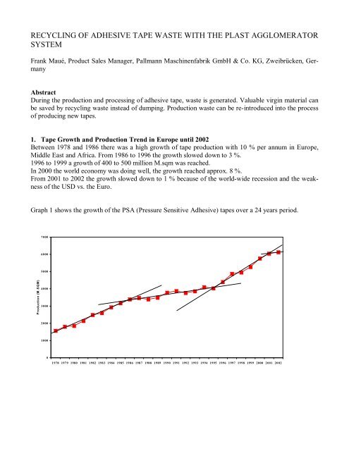
1. Tape Growth and Production Trend in Europe until 2002<br />
Between 1978 and 1986 <strong>the</strong>re was a high growth <strong>of</strong> <strong>tape</strong> production <strong>with</strong> 10 % per annum in Europe,<br />
Middle East and Africa. From 1986 to 1996 <strong>the</strong> growth slowed down to 3 %.<br />
1996 to 1999 a growth <strong>of</strong> 400 to 500 million M.sqm was reached.<br />
In 2000 <strong>the</strong> world economy was doing well, <strong>the</strong> growth reached approx. 8 %.<br />
From 2001 to 2002 <strong>the</strong> growth slowed down to 1 % because <strong>of</strong> <strong>the</strong> world-wide recession and <strong>the</strong> weakness<br />
<strong>of</strong> <strong>the</strong> USD vs. <strong>the</strong> Euro.<br />
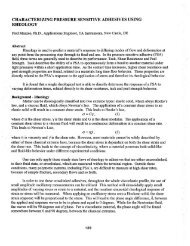
Graph 1 shows <strong>the</strong> growth <strong>of</strong> <strong>the</strong> PSA (Pressure Sensitive Adhesive) <strong>tape</strong>s over a 24 years period.<br />
Production (M.SQM)<br />
7000<br />
6000<br />
5000<br />
4000<br />
3000<br />
2000<br />
1000<br />
0<br />
1978 1979 1980 1981 1982 1983 1984 1985 1986 1987 1988 1989 1990 1991 1992 1993 1994 1995 1996 1997 1998 1999 2000 2001 2002
Graph 2 gives an indication <strong>of</strong> <strong>the</strong> split <strong>of</strong> <strong>the</strong> European production by countries.<br />
4500<br />
4000<br />
3500<br />
3000<br />
2500<br />
2000<br />
1500<br />
1000<br />
500<br />
0<br />
Italy <strong>with</strong> 3,9 B.sqm is <strong>the</strong> main producing country in Europe and in <strong>the</strong> world. The 2002 growth in<br />
Europe came mainly from Italy.<br />
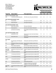
Graph 3 shows <strong>the</strong> European production by main application.<br />
5000<br />
4500<br />
4000<br />
3500<br />
3000<br />
2500<br />
2000<br />
1500<br />
1000<br />
500<br />
0<br />
M.SQM<br />
M.SQM<br />
Tape Production 2002 Growth vs 2001 (%)<br />
Italy GAS Spain/Greece/<br />
o<strong>the</strong>rs<br />
UK France/Benelux<br />
Tape Production 2002 Growth vs 2001<br />
Packaging Masking Sanitary Double Sided O<strong>the</strong>r specialty<br />
<strong>tape</strong>s<br />
Packaging <strong>with</strong> 74 % produced in Europe is <strong>the</strong> main enduse followed by masking <strong>with</strong> 10 % production<br />
in Europe.<br />
6<br />
4<br />
2<br />
0<br />
-2<br />
-4<br />
-6<br />
-8<br />
-10<br />
-12<br />
-14<br />
10<br />
8<br />
6<br />
4<br />
2<br />
0<br />
-2<br />
-4<br />
-6<br />
(%)
2. Size Reduction <strong>of</strong> Rubber Bales for <strong>the</strong> Production <strong>of</strong> Adhesives<br />
For <strong>the</strong> production <strong>of</strong> <strong>adhesive</strong>s, natural and syn<strong>the</strong>tic rubber is used. Depending on <strong>the</strong> type <strong>of</strong> rubber, a<br />
standard size rubber bale is cut down to granule size in a special guillotine knife mill <strong>with</strong>in seconds.<br />
Feeding <strong>the</strong> rubber granules to a mixer or dissolver vessel will shorten <strong>the</strong> mixing or dissolving time.<br />
The production capacity will be increased up to four times.<br />
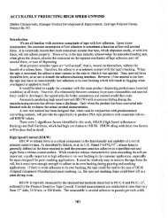
One step granulating <strong>system</strong><br />
Depending on <strong>the</strong> type <strong>of</strong> rubber, one step granulating <strong>system</strong>s <strong>with</strong> <strong>the</strong> rubber knife mill type PS-C can<br />
be used to granulate <strong>the</strong> standard bale sizes down to granule particle sizes smaller than 15 mm.<br />
1 2<br />
1. Belt conveyor<br />
2. Metal detector<br />
3. Guillotine knife mill<br />
3<br />
4. Pneumatic aspiration<br />
5. Dust collector<br />
In such a one step granulating <strong>system</strong>, <strong>the</strong> rubber bales are fed manually or by means <strong>of</strong> a conveyor belt<br />
via a bale feed chute into <strong>the</strong> rubber knife mill. The rubber bales are directly cut to end particle size <strong>with</strong><br />
a special guillotine rotor. The particle size is determined by <strong>the</strong> screen mesh size installed in <strong>the</strong> rubber<br />
knife mill. A pneumatic aspiration <strong>system</strong> sucks a certain quantity <strong>of</strong> air through <strong>the</strong> mill to cool <strong>the</strong> machine<br />
as well as to transport <strong>the</strong> granulated rubber out <strong>of</strong> <strong>the</strong> mill. The rubber granules are separated in a<br />
cyclone from <strong>the</strong> air and can be sacked and immediately stored or directly transported to <strong>the</strong> next processing<br />
step such as i.e. mixer or solvent tank.<br />
4<br />
5
Two Step Granulating System<br />
Two-step granulating <strong>system</strong>s are recommended when rubber bales from relatively insensitive types <strong>of</strong><br />
rubber are to be size reduced to particle sizes smaller than 4 mm.<br />
A conveyor belt feeds <strong>the</strong> rubber bales into a precutting mill <strong>with</strong> a special guillotine type rotor. This<br />
rotor precuts <strong>the</strong> bales into pieces smaller than 40 mm. Ano<strong>the</strong>r conveyor belt transports <strong>the</strong> rubber<br />
pieces from <strong>the</strong> first mill into a second mill. This mill also uses a guillotine type rotor which cuts <strong>the</strong><br />
product to <strong>the</strong> desired end size. The pneumatic aspiration <strong>system</strong> sucks <strong>the</strong> material out <strong>of</strong> <strong>the</strong> knife mill<br />
and transports it to <strong>the</strong> cyclone separator.<br />
In case <strong>of</strong> very heat sensitive rubber types, dusting agents can be added during <strong>the</strong> granulating process to<br />
prevent <strong>the</strong> sticking <strong>of</strong> <strong>the</strong> material. Depending on <strong>the</strong> particle size and <strong>the</strong> rubber type, between 2 and 5<br />
% <strong>of</strong> dusting agent is effectively needed for <strong>the</strong> dusting process. Overdosed dusting agent can be separated<br />
from <strong>the</strong> granules by means <strong>of</strong> a dusting agent recovery <strong>system</strong> and reused.<br />
1 2<br />
1. Belt conveyor<br />
2. Metal detector<br />
3. Guillotine knife mill<br />
3<br />
4<br />
5<br />
4. Belt conveyor<br />
5. Guillotine knife mill<br />
6. Peumatic aspiration<br />
6<br />
7. Dust collector<br />
7
Guillotine Type Rotor<br />
For economic size reduction <strong>of</strong> natural and syn<strong>the</strong>tic rubber a special guillotine type rotor was developed.<br />
The picture <strong>of</strong> <strong>the</strong> rotor shows that <strong>the</strong>re is no shaft straight through <strong>the</strong> rotor. The knives are arranged<br />
on knife carrier bars that connect <strong>the</strong> two rotating side discs, leaving <strong>the</strong> interior <strong>of</strong> <strong>the</strong> rotor completely<br />
open. This design guarantees a minimum <strong>of</strong> friction heat created during <strong>the</strong> granulation <strong>of</strong> rubber bales.<br />
The open rotor form prevents that <strong>the</strong> rubber granules are recompressed and conglutinated.<br />
Large air volume can be sucked through this type <strong>of</strong> rotor for considerable cooling during <strong>the</strong> cutting<br />
process.<br />
Knife mills <strong>with</strong> guillotine rotors, specially developed for <strong>the</strong> cutting <strong>of</strong> rubber bales, have flywheels<br />
mounted onto <strong>the</strong> rotor shaft to increase <strong>the</strong> rotor mass this prevents a reduction in speed when cutting a<br />
whole commercial-sized bale.
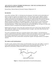
Layouts and Technical Data<br />
Rubber bale granulating <strong>system</strong>, type PS-C feeding a dissolver vessel<br />
1<br />
1) Monorail <strong>with</strong> vacuum lifter<br />
2) Conveyor belt <strong>with</strong> metal detector<br />
3) Infeed chute<br />
4) Guillotine knife mill<br />
5) Pneumatic aspiration<br />
6) Cyclone separator<br />
2<br />
Technical Data:<br />
Depending on <strong>the</strong> required throughput capacity different machine sizes <strong>with</strong> various throughput capacities<br />
are available.<br />
Type PS-C 4-5 4-7.5 6-6 6-9 8-12<br />
Capacity factor f 1.0 1.4 1.55 2.2 3.7<br />
Rotor diameter mm 400 400 600 600 800<br />
Rotor type G3 G3 G3 G3 WG6<br />
Motor kW 55 55-75 75-90 75-110 132-250<br />
Throughput capacity* kg/h 200-800 300-1100 350-1200 500-1700 700-3000<br />
3<br />
All dimensions and data mentioned above are for information only and must be confirmed by us. Technical<br />
changes to fur<strong>the</strong>r progress are reserved.<br />
The throughput rate varies <strong>with</strong> <strong>the</strong> type <strong>of</strong> rubber. O<strong>the</strong>r machine sizes available.<br />
5<br />
4<br />
8<br />
6<br />
7<br />
7) Rotary air lock<br />
8) Dissolver vessel<br />
9) Agitator<br />
10) Product pump<br />
11) Dust collector<br />
9<br />
10<br />
11
3. Size Reduction <strong>of</strong> Adhesive Tape<br />
The optimisation <strong>of</strong> production processes and <strong>the</strong> reprocessing <strong>of</strong> high quality raw materials are important<br />
targets <strong>of</strong> each producing and processing company which cares for its future. The use <strong>of</strong> a film <strong>recycling</strong><br />
installation is an important contribution to <strong>the</strong> set-up <strong>of</strong> a modern pr<strong>of</strong>itable production facility.<br />
When reducing film, <strong>the</strong> highest demands <strong>with</strong> regard to performance capabilities and mechanical<br />
strength are placed upon <strong>the</strong> granulator. An important pre-requisite for efficiently reducing very thin<br />
materials –like film- is <strong>the</strong> precise setting <strong>of</strong> <strong>the</strong> cutting gap. The precision <strong>with</strong> which <strong>the</strong> cutting gap<br />
can be set is a direct reflection <strong>of</strong> <strong>the</strong> efficiency <strong>of</strong> a granulator. Therefore a precise cutting gap guarantees<br />
an accurate cut.<br />
Specially developed film cutting knife mills <strong>with</strong> open rotors <strong>with</strong> cross scissors cut guarantees a specific<br />
quality <strong>of</strong> film flakes.
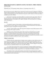
Principal <strong>of</strong> Operation<br />
Specially designed knife mills are able to produce pre-sized film flakes from <strong>adhesive</strong> <strong>tape</strong>s. The <strong>adhesive</strong><br />
<strong>tape</strong> from <strong>the</strong> roll is automatically unwound and fed to <strong>the</strong> knife mill by using a draw-in roller <strong>system</strong>,<br />
type PEV. Alternatively loose material can be fed to <strong>the</strong> mill from <strong>the</strong> side <strong>of</strong> <strong>the</strong> infeed chute. The<br />
material is size reduced between <strong>the</strong> rotor and stator knives. A screen keeps <strong>the</strong> material in <strong>the</strong> grinding<br />
chamber until <strong>the</strong> desired final size is achieved. The cut material is pneumatically sucked out <strong>of</strong> <strong>the</strong> machine<br />
and discharged into a storage bin through a cyclone separator.<br />
1<br />
2<br />
1) Unwinding station<br />
2) Adhesive <strong>tape</strong><br />
3) Infeed roller <strong>system</strong><br />
4) Hand feeding chute<br />
3<br />
Technical Data:<br />
Depending on <strong>the</strong> requirements <strong>of</strong> <strong>the</strong> customers, different sizes <strong>of</strong> machines are available for different<br />
throughput capacities.<br />
Type PS-F 4-5 4-7.5 4-10 4-12.5<br />
Capacity factor f 1.0 1.4 1.8 2.0<br />
Rotor diameter mm 400 400 400 400<br />
Rotor type G3 G3 G3 G3<br />
Motor kW 30 45 55 75<br />
Throughput capacity* kg/h 200-300 300-500 350-600 400-800<br />
All dimensions and data mentioned above are for information only and must be confirmed by us. Technical<br />
changes to fur<strong>the</strong>r progress are reserved.<br />
The throughput rate varies <strong>with</strong> <strong>the</strong> type <strong>of</strong> film. O<strong>the</strong>r machine sizes available.<br />
4<br />
5<br />
5) Knife mill<br />
6) Blower<br />
7) Conveying pipes<br />
8) Cyclone separator<br />
6<br />
7<br />
8
4. Agglomeration <strong>of</strong> Adhesive Tape<br />
As stated in paragraph 3, <strong>adhesive</strong> <strong>tape</strong> <strong>waste</strong> can size reduced to a flake form using a special type <strong>of</strong><br />
knife mill. Feeding <strong>the</strong> flakes back into <strong>the</strong> manufacturing process <strong>of</strong> new <strong>adhesive</strong> <strong>tape</strong> is quite difficult.<br />
Therefore it is recommended to produce a free-flowing granule out <strong>of</strong> <strong>the</strong> flakes <strong>with</strong> a high bulk density<br />
which is quite easy to transport, store and feed to an extrusion line. For this application, a Plast Agglomerator<br />
System, type PFV produces a high quality material out <strong>of</strong> <strong>the</strong> flakes. The size reduced flakes are<br />
conveyed into <strong>the</strong> storage bin <strong>of</strong> a Plast Agglomerator by means <strong>of</strong> a pneumatic conveying <strong>system</strong>. The<br />
storage bin <strong>of</strong> <strong>the</strong> Plast Agglomerator is equipped <strong>with</strong> two stirrers and a discharge screw. The stirrers<br />
keep <strong>the</strong> material moving and transport it to a discharge screw.<br />
The speed <strong>of</strong> <strong>the</strong> discharge screw is load-controlled by <strong>the</strong> drive motor <strong>of</strong> <strong>the</strong> Plast Agglomerator. A full<br />
and empty stage indicator is installed in <strong>the</strong> storage bin.<br />
By means <strong>of</strong> a screw, flanged to <strong>the</strong> main shaft <strong>of</strong> <strong>the</strong> agglomerating vane, <strong>the</strong> material is fed into <strong>the</strong><br />
agglomerating chamber <strong>of</strong> <strong>the</strong> Plast Agglomerator. With frictional heat, <strong>the</strong> material is sintered or <strong>plast</strong>ified<br />
and pressed through <strong>the</strong> holes <strong>of</strong> a special die and cut <strong>of</strong>f by rotating knives at <strong>the</strong> outer diameter <strong>of</strong><br />
<strong>the</strong> die.<br />
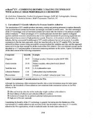
Agglomeration Chamber<br />
Material<br />
feeding<br />
Rotation <strong>of</strong><br />
knives<br />
Rotation <strong>of</strong> Rotor<br />
pressure<br />
piece<br />
Screw<br />
Die<br />
conveyor<br />
or
The agglomerating chamber is water-cooled using a double walled cooling disc and cooling ring. Product<br />
caking on <strong>the</strong> walls and overheating <strong>of</strong> <strong>the</strong> material is <strong>the</strong>reby avoided. The temperature <strong>of</strong> <strong>the</strong> material<br />
pressed through <strong>the</strong> holes <strong>of</strong> <strong>the</strong> die is measured by an infrared sensor. If <strong>the</strong> temperature rises over<br />
an adjustable set value, <strong>the</strong> discharge screw is shut <strong>of</strong>f and a malfunction is signalled on <strong>the</strong> control<br />
panel.<br />
The agglomerated material is pneumatically sucked <strong>of</strong>f and transported through a hot-melt granulator<br />
into a cyclone <strong>with</strong> a downstream conveyor fan. The air necessary for <strong>the</strong> conveying <strong>of</strong> <strong>the</strong> material is<br />
used at <strong>the</strong> same time for additional cooling <strong>of</strong> <strong>the</strong> Plast Agglomerator and heat dissipation from <strong>the</strong> hotmelt<br />
granulator.<br />
At <strong>the</strong> draw-in <strong>of</strong> <strong>the</strong> hot-melt granulator, <strong>the</strong> double walled housing is water-cooled.<br />
The end product size <strong>of</strong> <strong>the</strong> agglomerate is determined by <strong>the</strong> hole size <strong>of</strong> <strong>the</strong> screen installed in <strong>the</strong> hotmelt<br />
granulator.<br />
The material from <strong>the</strong> hot-melt granulator is discharged out <strong>of</strong> <strong>the</strong> cyclone separator via rotary air lock<br />
into a cascade sifter. A sifter fan in <strong>the</strong> cascade sifter produces an upward air stream. The air quantity in<br />
<strong>the</strong> cascade sifter can be adjusted by means <strong>of</strong> a secondary air regulator. The sifting fan pulls fines out<br />
<strong>with</strong> <strong>the</strong> air, which are returned via conveying pipe <strong>with</strong> cyclone to <strong>the</strong> Plast Agglomerator. De-dusted<br />
agglomerates free-fall to <strong>the</strong> bottom <strong>of</strong> <strong>the</strong> cascade sifter.<br />
A granule conveyor picks up <strong>the</strong> agglomerated material and conveys it, under negative pressure, to <strong>the</strong><br />
cyclone <strong>with</strong> a downstream fan. The granule conveying causes an air exchange in <strong>the</strong> <strong>system</strong> and<br />
<strong>the</strong>re<strong>with</strong> cools <strong>the</strong> agglomerated material. Depending on <strong>the</strong> type <strong>of</strong> material, a one-time product con-
veyance is sufficient for cooling. A downstream granule cooler is optional to prevent caking <strong>of</strong> <strong>the</strong><br />
agglomerate.<br />
Material fed into <strong>the</strong> granules cooler via rotary air lock is ba<strong>the</strong>d in an upward airflow and <strong>the</strong>reby<br />
cooled. The amount <strong>of</strong> cooling air is produced by a fan and can be adjusted by means <strong>of</strong> a regulating<br />
<strong>system</strong>. The heated exhaust air is discharged at <strong>the</strong> upper end <strong>of</strong> <strong>the</strong> granule cooler. Finest particles, carried<br />
away by <strong>the</strong> cooling air, are discharged in a cyclone and transported into a bin.<br />
Depending on <strong>the</strong> requirement, <strong>the</strong> agglomerate can be put into bags, air bags, big bags etc. after <strong>the</strong><br />
granule cooling process. The base frame must be constructed corresponding to each requirement. If <strong>the</strong><br />
room height is not sufficient, <strong>the</strong> material can be conveyed away from <strong>the</strong> cascade sifter or <strong>the</strong> granules<br />
cooler by means <strong>of</strong> a granules conveyor and can be filled into corresponding containers.<br />
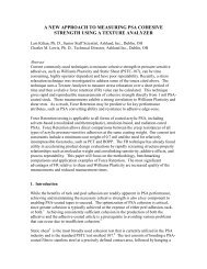
11<br />
10<br />
1) Knife mill<br />
2) Pneumamtic aspiration<br />
3) Hopper <strong>of</strong> PFV<br />
4) Plast Agglomerator<br />
9<br />
8<br />
7<br />
6<br />
5<br />
5) Piping<br />
6) Hot melt granulator<br />
7) Pneumatic aspiration<br />
8) Blower<br />
3<br />
4<br />
2<br />
9) Rotary air lock<br />
10) Zick zack sifter<br />
11) Granules cooler<br />
1
Technical Data<br />
Type PFV 120 200 250 315 400<br />
Capacity factor f 0,1 0,4 1,0 1,3 1,7<br />
Motor, Granulator kW 4-7,5 5,5-15 18,5-45 30-75 75-110<br />
Motor, Agglomerator kW 7,5-22 18,5-55 55-90 75-132 132-250<br />
Motor, Hot-melt granulator<br />
kW 3-5,5 7,5-18,5 22-30 30-45 45-55<br />
Total installed capacity kW 20-40 40-110 120-200 160-270 280-450<br />
Cooling water consumption<br />
l/h 100-200 200-300 300-500 500-700 700-1000<br />
Capacity kg/h 30-120 100-400 300-1000 400-1200 400-1900<br />
All dimensions and data mentioned above are for information only and must be confirmed by us. Technical<br />
changes to fur<strong>the</strong>r progress are reserved.<br />
Customers’ benefits<br />
♦ Continuous processing<br />
♦ High throughput capacity<br />
♦ Gentle agglomerating <strong>with</strong> frictional heat, <strong>with</strong>in fractions <strong>of</strong> a second, right below <strong>the</strong> melting point<br />
<strong>of</strong> <strong>the</strong> <strong>plast</strong>ic<br />
♦ Excellent end product, i.e. free flowing granules <strong>with</strong> a high bulk density<br />
♦ High flexibility<br />
♦ Fully automatic continuous operation, <strong>the</strong> <strong>system</strong> is designed for rough 3-shift operation<br />
♦ Low cost operation<br />
♦ Little space requirement as <strong>the</strong> <strong>system</strong> is constructed in compact, space-saving modular units<br />
♦ Minimum personnel requirements; material feeding <strong>of</strong> <strong>the</strong> granulator as well as <strong>the</strong> bagging <strong>of</strong> <strong>the</strong><br />
granules can be performed by one operator<br />
Conclusion<br />
The target <strong>of</strong> each producing company is to reduce costs.<br />
This paper script shows that a simple, small investment can be very effective in reducing <strong>the</strong> manufacturing<br />
costs <strong>of</strong> <strong>adhesive</strong>s.<br />
The paper also shows that in two steps, a free-flowing granule <strong>with</strong> a high bulk density can be produced<br />
out <strong>of</strong> film or <strong>adhesive</strong> <strong>tape</strong> <strong>waste</strong>.<br />
This inhouse <strong>waste</strong> which is expensive to dump can easily be fed back into <strong>the</strong> manufacturing process. It<br />
saves raw material as well as dumping costs.<br />
Since several years a complete <strong>adhesive</strong> <strong>tape</strong> <strong>recycling</strong> unit is installed at <strong>the</strong> company 3 M . On <strong>the</strong>ir<br />
web side “paragraph environmental” you can see <strong>tape</strong> <strong>waste</strong> as well an agglomerate. A certain percentage<br />
<strong>of</strong> <strong>the</strong> agglomerated <strong>tape</strong> <strong>waste</strong> is mixed <strong>with</strong> virgin pellets and used to produce new <strong>tape</strong>.
Acknowledgements<br />
The author wishes to thank <strong>the</strong> companies Exxon Mobil Chemical and 3M for <strong>the</strong>ir support during this<br />
study.
Recycling <strong>of</strong> Adhesive Tape Waste <strong>with</strong> Plast<br />
Agglomerator System<br />
Frank Maué<br />
Product Sales Manager<br />
PALLMANN MASCHINENFABRIK<br />
GmbH & Co.KG<br />
Wolfslochstr. 51<br />
66482 Zweibrücken<br />
Germany<br />
Biography:<br />
Tel: +49 6332 802–151<br />
Fax: +49 6332 802–528<br />
Email: frank.maue@pallmann.de<br />
Web Site: http://www.pallmann.de<br />
After an apprenticeship in mechanical Engineering, in 1983 Frank Maué<br />
registered at <strong>the</strong> Academy for Buisiness Administration in Blieskastel,<br />
Germany.<br />
1987 he graduated in Buisiness Administration.<br />
Since 1988 he has been working <strong>with</strong> Pallmann in Technical Sales for size<br />
reduction machines <strong>of</strong> <strong>plast</strong>ics.<br />
1995 Frank became Area Sales Manager for <strong>the</strong> North American and Middle<br />
East Market.<br />
Since 2001 Frank has been Product Sales Manager for applications <strong>of</strong> <strong>the</strong><br />
Film and Foam Industry world wide.