MARC Steam Turbines The Modular Steam Turbine Generation
MARC Steam Turbines The Modular Steam Turbine Generation
MARC Steam Turbines The Modular Steam Turbine Generation

You also want an ePaper? Increase the reach of your titles
YUMPU automatically turns print PDFs into web optimized ePapers that Google loves.
<strong>MARC</strong> ®<br />
<strong>Steam</strong> <strong><strong>Turbine</strong>s</strong><br />
<strong>The</strong> <strong>Modular</strong> <strong>Steam</strong> <strong>Turbine</strong> <strong>Generation</strong><br />
Engineering the Future – since 1758.<br />
MAN Turbo
2<br />
Originating from the Blohm+Voss shipyard, MAN Turbo AG Hamburg today combines<br />
the experience of a traditional company with state-of-the-art technology.
<strong>The</strong> first steam turbines under the name<br />
of Blohm+Voss were manufactured in<br />
1907, initially for ships built in the shipyard<br />
and subsequently for electric power<br />
generation. Since 1952 the company<br />
concentrated on developing and manufacturing<br />
industrial steam turbines. <strong>The</strong><br />
list of worldwide references encompasses<br />
more than 2,000 turbo generators.<br />
A wide range of renowned companies<br />
and utilities use our turbines, mainly in<br />
Industrial power plants<br />
Cogeneration plants<br />
Waste incineration plants<br />
Biomass power plants<br />
Combined Cycle plants<br />
Our modern manufacturing facilities in<br />
Hamburg are equipped with machine<br />
tools of high performance and cover a<br />
floor area of more than 10,000 m2 . <strong>The</strong><br />
quality management system is certified<br />
to DIN EN ISO 9001. Centrally situated<br />
in the free-port of Hamburg, MAN Turbo<br />
offers ideal transport links, enabling<br />
even large components to be transported<br />
with ease.<br />
3
<strong>The</strong> concept<br />
<strong>The</strong> customers’ demand on durability, efficiency and economy has always had<br />
top priority for the development of BVI steam turbines. <strong>The</strong> result of our permanent<br />
development is a solution that sets new standards: <strong>The</strong> <strong>MARC</strong> (<strong>Modular</strong><br />
ARrangement Concept) turbine series has proven its high quality throughout<br />
more than 100 installations since its market introduction in 1998. This modular<br />
turbine concept allows a flexible arrangement of the auxiliary components and<br />
enables the overall assembly to be set up in line with individual requirements.<br />
4
<strong>The</strong> turbo generator unit comprises the<br />
following modules:<br />
<strong>Steam</strong> turbine<br />
Gearbox/generator unit<br />
LP lubricating oil system<br />
HP control oil system<br />
Control cabinet<br />
<strong>The</strong> lubricating oil module, control oil<br />
module and the control cabinet can be<br />
individually arranged around the unit.<br />
<strong>MARC</strong> <strong><strong>Turbine</strong>s</strong><br />
<strong>Modular</strong> ARangement Concept<br />
<strong>MARC</strong> 1 <strong>MARC</strong> 2<br />
<strong>MARC</strong> 4<br />
<strong>MARC</strong> 6<br />
<strong>MARC</strong> 8<br />
Electric power<br />
up to 3 MW<br />
Max. flange diameter<br />
Live steam: 125<br />
Exhaust: 700<br />
Max. live steam conditions<br />
30 bar(a) / 480°C<br />
up to 15,000 1/min<br />
Electric power<br />
up to 12 MW<br />
Max. flange diameter<br />
Live steam: 200<br />
Exhaust: 1,200<br />
Max. live steam conditions<br />
90 bar(a) / 520°C<br />
up to 12,000 1/min<br />
Electric power<br />
up to 22 MW<br />
Max. flange diameter<br />
Live steam: 250<br />
Exhaust: 1,500<br />
Max. live steam conditions<br />
120 bar(a) / 520°C<br />
up to 10,000 1/min<br />
Benefits of the modular concept:<br />
Proven turbine design with robust<br />
technology and high availability<br />
Space-saving, low-noise epicyclic<br />
gear generator unit (up to 25 MW)<br />
High level of efficiency thanks to<br />
optimised turbine design and use of<br />
epicyclic gearing<br />
Use of proven system modules for<br />
lubricating oil and control oil<br />
Compact control cabinet as blackbox<br />
for connection via bus system<br />
to the central control system<br />
Low investment costs<br />
Electric power<br />
up to 35 MW<br />
Max. flange diameter<br />
Live steam: 300<br />
Exhaust: 2,200<br />
Max. live steam conditions<br />
120 bar(a) / 530°C<br />
up to 8,000 1/min<br />
Electric power<br />
up to 50 MW<br />
Max. flange diameter<br />
Live steam: 350<br />
Exhaust: 2,600<br />
Max. live steam conditions<br />
120 bar(a) / 530°C<br />
up to 6,000 1/min<br />
Five different turbine sizes cover a performance<br />
range from 1.5 MW to 50 MW.<br />
<strong>The</strong> <strong>MARC</strong> production programme<br />
includes backpressure, heating and<br />
condensing turbines that can also be<br />
fitted with extraction and bleed ports.<br />
Explanation of type codes:<br />
<strong>MARC</strong> x - A B C<br />
x–Code for turbine size<br />
A– Code for turbine type<br />
C: Condensing<br />
B: Backpressure<br />
H: Heating<br />
B– Number of controlled extractions<br />
C– Number of bleed ports<br />
5
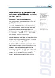
<strong>Turbine</strong> type B:<br />
Backpressure<br />
Backpressure turbines are used as generator<br />
drive units in combined heat and<br />
power plants and for on-site electricity<br />
generation of industrial facilities. <strong>The</strong>y<br />
are also used in cogeneration applications.<br />
6<br />
<strong>Turbine</strong> type C:<br />
Condensing<br />
<strong>The</strong> areas of application for condensation<br />
turbines range from turbo generators<br />
for industrial power plants and<br />
waste incineration systems through to<br />
biomass facilities.<br />
<strong>The</strong> extraction steam is typically used<br />
for heating, production purposes and<br />
feed water prewarming. To achieve optimum<br />
part-load efficiency, the LP part<br />
can also provided with a nozzle group<br />
control.<br />
<strong>Turbine</strong> type H:<br />
Heating<br />
<strong>The</strong> typical application is electricity<br />
and heat generation. <strong>The</strong> special feature<br />
of this turbine type is the double-flow<br />
exhaust for connect-ing a two stage<br />
heating system. This design provides<br />
the most efficient way of electricity and<br />
heat production throughout the year.
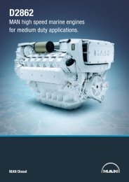
<strong>The</strong> new <strong>MARC</strong> 1<br />
<strong>The</strong> success formula of the <strong>MARC</strong> 2 has been transferred to a new <strong>MARC</strong> model in the power<br />
range of 1.5 - 3 MW. Built on the design principles of proven turbines and the positive operational<br />
experience gained, the new <strong>MARC</strong> 1 turbo generator has been developed specifically for<br />
use in the smaller segment of biomass applications.<br />
With the <strong>MARC</strong> concept developed in<br />
the mid-1990’s, MAN Turbo has successfully<br />
established itself in the biomass<br />
power plant market sector from<br />
4 - 20 MW electrical output. MAN Turbo’s<br />
operational experience with steam tur-<br />
bines previously supplied for biomass<br />
power plants provides compelling evidence<br />
of the economic efficiency and<br />
operational reliability of this concept.<br />
7
<strong>Turbine</strong> module<br />
In industrial turbines, part of the steam<br />
often is extracted for production purposes,<br />
heating steam systems or generative<br />
feed water heating. In that case,<br />
in addition to several bleedings, two<br />
controlled extractions can also be provided.<br />
<strong>The</strong> <strong>MARC</strong> concept allows an<br />
individual and optimized design of the<br />
different turbine elements, according to<br />
specific requirements, such as the pressure<br />
level and the extraction steam<br />
quantity.<br />
Depending on the live steam conditions<br />
and the specified operation mode, either<br />
a nozzle group control with or without<br />
bypass or a throttle control may be se-<br />
8<br />
lected. <strong>The</strong> control stage, either single<br />
or two-row type, and the number of reaction<br />
stages are especially adapted to<br />
the specific requirements. For all reaction<br />
stages the low-loss round-head<br />
profile is used.<br />
<strong>The</strong> HP blades are provided with milled<br />
shrouds, whereas the last blade rows<br />
are mostly designed with conically twisted<br />
blades, the blade ends of which<br />
being tip-thinned on one side.<strong>The</strong> rotor<br />
blades of the last rows are grouped by<br />
means of damping and bind-ing wires in<br />
conformity with the results of vibration<br />
calculations. Due to the small flow<br />
volume, steam admission of the im-<br />
pulse wheel is only necessary in the<br />
upper casing half, how-ever, the lower<br />
half can also be utilized, if required. In<br />
that case, a bypass leads to the lower<br />
nozzle group.<br />
<strong>The</strong> exhaust casing is a welded construction<br />
and may either be fitted facing<br />
upward or downward, depending on<br />
the site conditions. <strong>MARC</strong> steam turbines<br />
have been designed for highest<br />
operating security and utmost reliability.<br />
As the highest thermal impact on the<br />
steam carrying parts occurs at load<br />
changes, the casing, guide blade carrier<br />
and inner casing have been developed<br />
for a high thermal elasticity.
<strong>The</strong> following design features apply<br />
for all turbine types:<br />
multi-stage reaction design<br />
maximum symmetry of the upper<br />
and lower casings<br />
symmetrical temperature distribution<br />
at the circumference in all crosssections<br />
under all load conditions<br />
single-piece forged rotor<br />
labyrinth sealing glands between<br />
rotor and casing<br />
split tilting pad sleeve bearings<br />
self-aligning axial bearing, for doublesided<br />
loading<br />
nozzle group control<br />
guide blade carrier<br />
<strong>Turbine</strong> rotors<br />
<strong>The</strong> reaction turbines are supplied with<br />
a drum-type rotor. <strong>The</strong> turbine rotors,<br />
the balance piston and the impulse<br />
wheel disc as well as the subsequent<br />
drum parts are solid forging of high temperature<br />
material.<strong>The</strong> rotor design is<br />
based on modern calculation methods<br />
to meet the highest demands regarding<br />
smooth and resonant-free operation.<br />
<strong>The</strong> bladed rotors are statically and dynamically<br />
bal-anced at operating speed<br />
in a modern high-speed vacuum balancing<br />
plant, in a way that the shaft vibrations<br />
over the whole speed range<br />
are considerably below ISO10816 permitted<br />
values.<br />
Bearings<br />
<strong>The</strong> radial bearings are of multiface<br />
sleeve or tilting pad type. A stable rotor<br />
position is maintained by hydrodynamical<br />
oil wedges, equally spaced on the<br />
circumference.<strong>The</strong> axial forces resulting<br />
from pressure differences in the blading<br />
are mainly absorbed by the balance<br />
piston. A double-sided segmental axial<br />
bearing absorbs the residual thrust and<br />
the coupling forces.<br />
9
Bearing Pedestals<br />
<strong>The</strong> bearings are located in two bearing<br />
pedestals on which the turbine casing<br />
rests by means of brackets on the level<br />
of the horizontal joint. <strong>The</strong> exhaust connection<br />
of condensing turbines rests on<br />
lateral supports on the level of the horizontal<br />
joint. Due to this form of arrangement,<br />
the position of the rotor to the<br />
casing and thus, the radial blade clearance<br />
remain virtually constant under all<br />
load and temperature conditions.<br />
10<br />
Labyrinth Sealing Glands<br />
<strong>The</strong> steam sealing between the turbine<br />
rotor and the casing located at the<br />
casing’s ends as well as at the balance<br />
piston is a labyrinth sealing type. <strong>The</strong><br />
sealing strips of high-temperature material<br />
are caulked into the rotor.<br />
Blading<br />
In the blading, consisting of control<br />
stage and reaction part, the potential<br />
energy of the high-pressure steam is<br />
converted into mechanical energy.<br />
Control Stage<br />
Due to partial admission, a high degree<br />
of dynamical tension occurs in the<br />
blades of the control stage. This tension<br />
is reduced by grouping the blades in the<br />
shrouding.Highly loaded control stages<br />
are designed with blade triplets, meaning<br />
that three blades having one root<br />
together are machined from one workpiece.
Reaction Part<br />
<strong>The</strong> multi-stage reaction blading ensures<br />
utmost reliability and economy due to<br />
high mechanical and thermal<br />
strengthen both guide blades and<br />
rotor blades to withstand operating<br />
stress<br />
a large sectional modulus to avoid<br />
vibrations.<br />
low flow losses in the blading covering<br />
a wide operating range.<br />
<strong>The</strong> guide and rotor blades have the<br />
same profile. It was theoretically and<br />
experimentally tested during its development.<br />
Hereby, the characteristics of<br />
the profile, depending on the cascade<br />
arrangement and the entry angles, were<br />
determined by measurements in a plane<br />
wind tunnel.<br />
A characteristic feature of partload operation<br />
is the entry angle deviating from<br />
the normal line of flow. <strong>The</strong> impact-free<br />
entry angle range is very large and ensures<br />
a high part load efficiency at operating<br />
conditions different from those of<br />
rated load.<br />
<strong>The</strong> clearance and rim losses of backpressure<br />
turbines and high-pressure<br />
parts of condensing turbines are reduced<br />
to a minimum by using shrouds.<br />
<strong>The</strong> blade with root and shroud is<br />
machined from one piece. After blading<br />
the rotor, the shrouding is machined to<br />
its form. Regarding stages with a low<br />
clearance loss factor, the blade tips are<br />
provided with a one-sided thinning.<br />
11
Control mechanism<br />
<strong>The</strong> steam control valves of <strong>MARC</strong> turbines<br />
are of a diffuser type. Small valve<br />
dimensions allow a vast number of valves<br />
and nozzle groups. Consequently,<br />
the throttling losses are kept low also at<br />
part load. <strong>The</strong> cone form of the valve<br />
has been optimized regarding the flow.<br />
Valve spindles, valve cone and valve<br />
bar consist of heat-resistant steel with<br />
hardened, wear-resistant surface. <strong>The</strong><br />
hardening is effected via a plasmahardening<br />
process.<br />
12<br />
Due to the small valve dimensions, the<br />
steam control valves can be actuated<br />
directly. This so-called group drive is<br />
a compact and reliable solution. <strong>The</strong><br />
actuator is a single acting hydraulic<br />
cylinder which is fed by the control oil<br />
system at an oil pressure of 160 bar.<br />
On turbine tripping or full-load disconnection<br />
the valves are closed by<br />
the pre-loaded spring, thus, protecting<br />
the turbine plant at malfunctions. If the<br />
pressure in the control oil system decreases,<br />
both the control valves and the<br />
tripping devices will be closed automa-<br />
tically, as they act on the same principle<br />
(single-acting hydraulic piston against<br />
pre-loaded spring). This means double<br />
security for the turbine and the steam<br />
system. A lever system for parallel motion<br />
of both valve spindles precisely<br />
transmits changes of the controller output<br />
onto the valve bar and – depending<br />
on the valve lift – on one or more valve<br />
cones. <strong>The</strong> moving parts are made of<br />
non-corrosive and maintenance-free<br />
self-lubricating material. <strong>The</strong> valve<br />
spindles are sealed by maintenancefree,<br />
pre-compressed graphite laminated<br />
glands, and reinforced carbon<br />
guide bushes.
Gearbox/Generator module<br />
Gearbox and generator are installed as<br />
one compact unit. For the <strong>MARC</strong> 2 and<br />
the <strong>MARC</strong> 4, generally an epicyclic<br />
gearbox is used which is flanged directly<br />
to the generator. For the types <strong>MARC</strong> 6<br />
and <strong>MARC</strong> 8 either an epicyclic or a<br />
helical gearbox is used, depending on<br />
power and speed.<br />
<strong>The</strong> application of epicyclic gearboxes<br />
bear the following advantages:<br />
<strong>The</strong> offset usually caused by a helical<br />
gearbox is avoided, which greatly facilitates<br />
the alignment. Moreover, one<br />
coupling and the high-speed gear<br />
bearing are omitted which improves<br />
the total efficiency.<br />
13
Lubrication oil module<br />
<strong>The</strong> lubrication oil system* is a compact<br />
module designed as a low-pressure oil<br />
system for turbine, gearbox and generator,<br />
consisting of:<br />
14<br />
Lubrication oil system <strong>Turbine</strong> Gearbox and<br />
generator<br />
complete set of 2 main oil pumps<br />
emergency oil pump with DC motor<br />
oil cooler<br />
redundant oil filter<br />
oil mist fan<br />
temperature control valve<br />
pressure control valve<br />
* For <strong>MARC</strong>1: Combined lubrication<br />
and control oil system.<br />
Diagram of the<br />
lubrication oil system<br />
1 <strong>Turbine</strong><br />
2 Turning gear<br />
3 Extraction<br />
4 Exhaust steam<br />
5 LP control valvel<br />
6 HP control valve<br />
7 Trip valve<br />
8 Gearbox<br />
9 Generator<br />
10 Oil tank<br />
11 Main oil pump 1<br />
12 Main oil pump 2<br />
13 Emergency oil pump<br />
14 Oil cooler with cooling<br />
water connections<br />
15 Oil filter<br />
16 Oil mist fan
Control oil module<br />
Control oil system <strong>Turbine</strong> Gearbox and<br />
generator<br />
<strong>The</strong> control oil system is a compact<br />
module. <strong>The</strong> main components are:<br />
oil tank designed as base frame<br />
main oil pump with AC motor<br />
pressure tank<br />
redundant oil filter<br />
bypass pump<br />
oil cooler<br />
measuring and control system<br />
Apart from the control valves, the system<br />
also feeds the live steam trip valve and, if<br />
necessary, the extraction-trip valves and<br />
control devices in the extraction with a<br />
system pressure of 160 bar, commonly<br />
used for hydraulic systems.<br />
Diagram of the<br />
control oil system<br />
1 <strong>Turbine</strong><br />
2 Gearbox<br />
3 Turning gear<br />
4 Generator<br />
5 LP control valve<br />
6 HP control valve<br />
7 HP trip valve<br />
8 Extraction non-return<br />
flap<br />
9 <strong>Turbine</strong> governor<br />
10 Generator cooler<br />
11 Extraction<br />
12 Exhaust steam<br />
13 Oil tank<br />
14 Circulation pump<br />
15 Control oil pump<br />
16 Control oil cooler<br />
17 Pressure tank<br />
15
Measuring and Control System<br />
16<br />
Ethernet<br />
or<br />
Profibus<br />
Hardware<br />
Data storage<br />
Central Processing Unit<br />
(CPU)<br />
Vibration<br />
monitoring<br />
Overspeed<br />
protection<br />
Generator<br />
protection<br />
Voltage<br />
controller<br />
cos<br />
controller<br />
Control cabinet<br />
<strong>The</strong> turbo set control cabinet is a compact<br />
unit that can be arranged flexibly<br />
around the turbine unit. All control<br />
functions and protection of the turbine<br />
and generator are integrated in a single<br />
control box with a user interface on the<br />
front. This saves space and ensures minimal<br />
installation and commissioning<br />
time.<br />
All desired signals can be sent via a<br />
databus (e.g. Ethernet or Profibus) to a<br />
host control system, and operational<br />
commands and setpoint values can be<br />
received from there.<br />
Function<br />
<strong>Turbine</strong> open-loop<br />
controller<br />
<strong>Turbine</strong> closed-loop<br />
controller<br />
<strong>Turbine</strong> protection<br />
and monitoring<br />
Generator<br />
protection<br />
Generator<br />
controller<br />
Control system<br />
In order to maintain flexibility when meeting<br />
the varied process requirements,<br />
the turbine control system is implemented<br />
in the modern programmable logic<br />
control (PLC) system S7-400. <strong>The</strong> comprehensive<br />
range of modules enables<br />
flexible and user-friendly handling of a<br />
wide range of communication options<br />
to other systems and problem-free<br />
expansion, should additional tasks be<br />
required. Startup, shutdown and operation<br />
of the entire turbine unit are completely<br />
automated in the control system,<br />
with ease of use being one of its key<br />
features.<br />
Based on many years of experience in<br />
the field of turbo generator operation,<br />
we have developed a digital steam turbine<br />
controller. <strong>The</strong> inte-gration of this<br />
controller in the existing control system<br />
hardware enables a contin-uous control<br />
concept and optimal integration of the<br />
controller without additional interfaces.<br />
<strong>The</strong> steam turbine controller is a powerful<br />
and flexible device. Speed, output,<br />
pressure and temperature are optimally<br />
controlled and critical variables are<br />
limited. All control modes are seamlessly<br />
integrated.
Control cabinet<br />
Field<br />
ISDN<br />
Router<br />
External<br />
Trips<br />
<strong>Turbine</strong><br />
trip valve<br />
Control room<br />
Measurement<br />
transducer<br />
Ethernet or Profibus<br />
MP270-B SIMATIC CPU 414 - DP I/O Rack<br />
Data Logger<br />
PC<br />
<strong>Turbine</strong><br />
Operation<br />
<strong>The</strong> turbo generator can be operated<br />
either via a central control system or locally,<br />
directly via the operator interface<br />
on the control panel. In automatic mode<br />
only the turbine start/stop commands<br />
and specification of the setpoint values<br />
are required. All operating modes and<br />
fault messages are displayed locally and<br />
supplied to the control system via a bus<br />
system. In manual mode, local control<br />
of the auxiliary modules and components<br />
is possible.<br />
Pressure<br />
Temperature<br />
Vibrations<br />
Hardwired<br />
Profibus<br />
PC<br />
Generator<br />
protection<br />
Limit switch<br />
Control box<br />
Overspeed<br />
protection<br />
Hardwired<br />
Safety<br />
All turbine units are provided with extensive<br />
safety equipment that safely shuts<br />
down the steam turbine and generator<br />
when critical conditions are reached.<br />
<strong>The</strong> classification of safety criteria is in<br />
accordance with IEC 61508. Measurement<br />
systems, trip and alarm criteria are<br />
specified in such a way that an optimal<br />
balance between machinery protection<br />
and availability is achieved. If desired,<br />
the design also enables unattended<br />
24-hr operation.<br />
Lubrication Oil<br />
Control Oil<br />
Voltage<br />
controller<br />
Emergency<br />
switch-off<br />
Condenser<br />
Low voltage<br />
switchgear<br />
Mean voltage<br />
switchgear<br />
Hardwired<br />
Remote access<br />
A datalogger with ISDN interface enables<br />
remote support for your operating<br />
personnel: Important operating data is<br />
saved to a datalogger and can be analysed<br />
by our Service Team, while our<br />
service engineers have direct access to<br />
the control system and control panel.<br />
This enables us to provide you with<br />
quick and cost-effective support.<br />
17
Quality Assurance<br />
<strong>The</strong> most important principle of turbine<br />
manufacture is to ensure high quality<br />
standards for all components. <strong>The</strong><br />
turbines are subjected to the following<br />
checks during the manufacturing<br />
process.<br />
18<br />
Material inspections<br />
Castings inspection<br />
Production inspection<br />
Assembly inspection<br />
Continuous quality control is ensured<br />
by the ISO 9001 quality management<br />
system.<strong>The</strong> turbine and baseframe are<br />
erected and the internal piping is installed<br />
on the assembly bed. <strong>The</strong> gearing/generator<br />
modular unit is assembled<br />
at the generator manufacturer and<br />
subjected to a functional check. As with<br />
the other modules, both oil modules are<br />
tested at the manufacturer prior to their<br />
installation adjacent to the turbine on<br />
site.<br />
In order to meet the requirements for<br />
quiet running, operational safety and<br />
high availability of the steam turbines,<br />
each turbine rotor is subjected to highspeed<br />
dynamic balancing and spin<br />
testing in a vacuum spin test facility.<br />
After this acceptance test the rotor can<br />
be installed.
Service<br />
Our experienced <strong>Turbine</strong> Service<br />
Department ensures the professional<br />
installation of the supplied turbine unit,<br />
including commissioning and trial operation.<br />
<strong>The</strong> operating personnel concurrently<br />
receive training as required.<br />
MAN Turbo provides person-al consultancy<br />
and optimum support for service<br />
and repair work as well as for retrofitting.<br />
Maintenance and revisions are<br />
coordinated between our service<br />
department and the customer. Our<br />
experienced service staff is available<br />
night and day to assure the recommissioning<br />
of the plant.<br />
19
MAN Turbo AG<br />
Steinbrinkstrasse 1<br />
46145 Oberhausen/Germany<br />
Phone +49. 208. 6 92-01<br />
Fax +49. 208. 6 92-20 19<br />
www.manturbo.com<br />
MAN Turbo – a member of the MAN Group<br />
In the interests of technical progress,<br />
subject to change without notice.<br />
Printed in Germany. December 2008<br />
Turbo 1002 e 1208 1.5 ba