Series 1170, LF1170, L1170 and LFL1170 - Watts Water ...
Series 1170, LF1170, L1170 and LFL1170 - Watts Water ...
Series 1170, LF1170, L1170 and LFL1170 - Watts Water ...

You also want an ePaper? Increase the reach of your titles
YUMPU automatically turns print PDFs into web optimized ePapers that Google loves.
IS-<strong>1170</strong>-M2_L<strong>1170</strong>-M2<br />
<strong>Series</strong> <strong>1170</strong>, LF<strong>1170</strong>, L<strong>1170</strong> <strong>and</strong> LFL<strong>1170</strong><br />
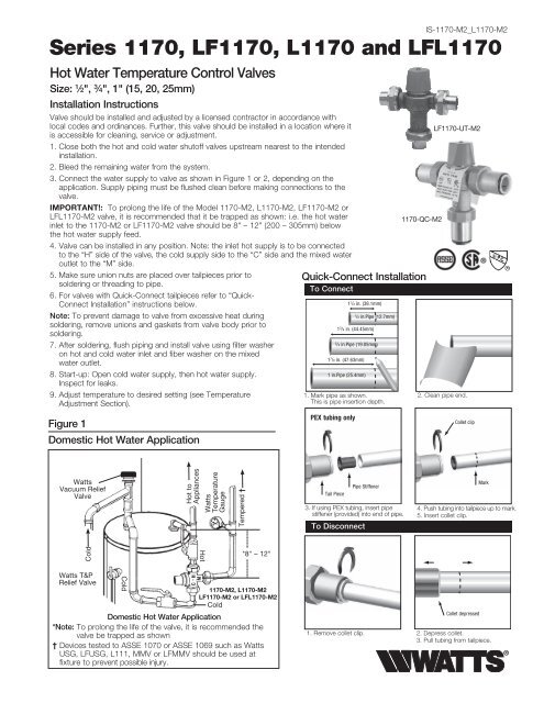
Hot <strong>Water</strong> Temperature Control Valves<br />
Size: 1 ⁄2", 3 ⁄4", 1" (15, 20, 25mm)<br />
Installation Instructions<br />
Valve should be installed <strong>and</strong> adjusted by a licensed contractor in accordance with<br />
local codes <strong>and</strong> ordinances. Further, this valve should be installed in a location where it<br />
is accessible for cleaning, service or adjustment.<br />
1. Close both the hot <strong>and</strong> cold water shutoff valves upstream nearest to the intended<br />
installation.<br />
2. Bleed the remaining water from the system.<br />
3. Connect the water supply to valve as shown in Figure 1 or 2, depending on the<br />
application. Supply piping must be flushed clean before making connections to the<br />
valve.<br />
IMPORTANT!: To prolong the life of the Model <strong>1170</strong>-M2, L<strong>1170</strong>-M2, LF<strong>1170</strong>-M2 or<br />
LFL<strong>1170</strong>-M2 valve, it is recommended that it be trapped as shown: i.e. the hot water<br />
inlet to the <strong>1170</strong>-M2 or LF<strong>1170</strong>-M2 valve should be 8" – 12" (200 – 305mm) below<br />
the hot water supply feed.<br />
4. Valve can be installed in any position. Note: the inlet hot supply is to be connected<br />
to the “H” side of the valve, the cold supply side to the “C” side <strong>and</strong> the mixed water<br />
outlet to the “M” side.<br />
5. Make sure union nuts are placed over tailpieces prior to<br />
soldering or threading to pipe.<br />
6. For valves with Quick-Connect tailpieces refer to “Quick-<br />
Connect Installation” instructions below.<br />
Note: To prevent damage to valve from excessive heat during<br />
soldering, remove unions <strong>and</strong> gaskets from valve body prior to<br />
soldering.<br />
7. After soldering, flush piping <strong>and</strong> install valve using filter washer<br />
on hot <strong>and</strong> cold water inlet <strong>and</strong> fiber washer on the mixed<br />
water outlet.<br />
8. Start-up: Open cold water supply, then hot water supply.<br />
Inspect for leaks.<br />
9. Adjust temperature to desired setting (see Temperature<br />
Adjustment Section).<br />
Figure 1<br />
Domestic Hot <strong>Water</strong> Application<br />
<strong>Watts</strong><br />
Vacuum Relief<br />
Valve<br />
Cold<br />
<strong>Watts</strong> T&P<br />
Relief Valve<br />
Cold<br />
Hot to<br />
Appliances<br />
H<br />
M<br />
<strong>Watts</strong><br />
Temperature<br />
Gauge<br />
Hot<br />
Tempered †<br />
*8" – 12"<br />
<strong>1170</strong>-M2, L<strong>1170</strong>-M2<br />
LF<strong>1170</strong>-M2 or LFL<strong>1170</strong>-M2<br />
Cold<br />
Domestic Hot <strong>Water</strong> Application<br />
*Note: To prolong the life of the valve, it is recommended the<br />
valve be trapped as shown<br />
† Devices tested to ASSE 1070 or ASSE 1069 such as <strong>Watts</strong><br />
USG, LFUSG, L111, MMV or LFMMV should be used at<br />
fixture to prevent possible injury.<br />
C<br />
Quick-Connect Installation<br />
To Connect<br />
1. Mark pipe as shown.<br />
This is pipe insertion depth.<br />
PEX tubing only<br />
Tail Piece<br />
1 1 /2 in. (38.1mm)<br />
1 3 /4 in. (44.45mm)<br />
3 /4 in.Pipe (19.05mm)<br />
1 7 /8 in. (47.63mm)<br />
1 in.Pipe (25.4mm)<br />
3. If using PEX tubing, insert pipe<br />
stiffener (provided) into end of pipe.<br />
To Disconnect<br />
1 /2 in.Pipe (12.7mm)<br />
Pipe Stiffener<br />
<strong>1170</strong>-QC-M2<br />
LF<strong>1170</strong>-UT-M2<br />
2. Clean pipe end.<br />
Collet clip<br />
Mark<br />
4. Push tubing into tailpiece up to mark.<br />
5. Insert collet clip.<br />
Collet depressed<br />
1. Remove collet clip. 2. Depress collet.<br />
3. Pull tubing from tailpiece.
Figure 2<br />
Radiant Heat Application<br />
from Boiler<br />
to Boiler<br />
<strong>Watts</strong> Flow<br />
Check <strong>Watts</strong><br />
Ball Valve<br />
<strong>1170</strong>-M2,<br />
L<strong>1170</strong>-M2<br />
CV, CVS<br />
Check Valve<br />
Figure 3<br />
Temperature Adjustment<br />
Factory Preset:<br />
<strong>1170</strong>-M2, LF<strong>1170</strong>-M2: 120°F (49°C)<br />
L<strong>1170</strong>-M2, LFL<strong>1170</strong>-M2: 90°F (31°C)<br />
Under following conditions:<br />
Cold Inlet: 60-70°F (16-21°C)<br />
Hot Inlet: 140-145°F (60-63°C)<br />
Supply Pressure: 45psi (3.15 bar)<br />
Hotter<br />
TP<br />
Test Plug<br />
RPV<br />
Colder<br />
3 /32" Hex Wrench<br />
1. Let water flow for at least two minutes to allow supply temperature<br />
to stabilize.<br />
2. Calibrate the mixed water outlet temperature by placing a<br />
thermometer in the mixed water stream.<br />
3. To adjust the setting of the valve, loosen locking cap screw<br />
with hex wrench, see Figure 3. Cap must be lifted 1/4" to<br />
adjust temperature. To increase the temperature, turn counterclockwise.<br />
To decrease temperature turn clockwise.<br />
4. Lower h<strong>and</strong>le <strong>and</strong> tighten screw.<br />
5. Check outlet temperature.<br />
Turn<br />
<strong>Watts</strong><br />
Ball Valve<br />
Circulator<br />
Mixed<br />
to Radiant<br />
Cold<br />
Radiant Return<br />
Unscrew, lift<br />
cap to adjust<br />
Period Inspection/Maintenance<br />
This valve requires periodic inspection <strong>and</strong> verification of the outlet<br />
temperature by a licensed contractor. Corrosive water conditions,<br />
hot inlet water temperature over 200°F (93°C), unauthorized<br />
adjustments or repairs could render the valve ineffective for<br />
its intended service. Regular cleaning <strong>and</strong> checking of thermostat<br />
assembly helps to maximize valve life <strong>and</strong> mixing function.<br />
Frequency of cleaning depends on local water conditions.<br />
Pressure — Temperature<br />
Minimum Supply Pressure (Static): 30psi (207 kPa)<br />
Inlet Temperatures: hot inlet, 120°F – 200°F (49°C – 93°C),<br />
cold inlet, 40°F – 85°F (4°C – 29°C)<br />
Hot <strong>Water</strong> Inlet to Outlet Differential Temperature: 5°F (3°C)<br />
<strong>1170</strong>-M2, LF<strong>1170</strong>-M2 Temperature Out:<br />
Field range: 90°F – 160°F (32°C – 71°C), adjustable.<br />
Accurate within ±3°F (1.7°C)<br />
L<strong>1170</strong>-M2 <strong>and</strong> LFL<strong>1170</strong>-M2 Temperature Out:<br />
Field range: 60°F – 120°F (16°C – 49°C), adjustable.<br />
Accurate within ±3°F (1.7°C)<br />
Maximum Temperature: 200°F (93°C)<br />
Maximum Pressure: 150psi (10.3 bar)<br />
Maximum Pressure Differential Between Hot <strong>and</strong> Cold<br />
<strong>Water</strong> Supplies: 25%.<br />
Approval: CSA B125 certified<br />
Listing: ASSE 1017 <strong>and</strong> IAPMO UPC<br />
!<br />
WARNING<br />
<strong>Watts</strong> Hot <strong>Water</strong> Temperature Control Valves cannot be used for tempering<br />
water temperature at fixtures. Severe bodily injury (i.e. scalding or chilling)<br />
<strong>and</strong>/or death may result depending upon system water pressure changes.<br />
ASSE St<strong>and</strong>ard 1016, ASSE 1070 listed devices such as <strong>Watts</strong> Model L111,<br />
LFL111 <strong>Series</strong> USG, LFUSG, MMV or LFMMV should be used at fixtures<br />
to prevent possible injury. The <strong>Watts</strong> Hot <strong>Water</strong> Temperature Control Valves<br />
are designed to be installed at or near the boiler or water heater. They are not<br />
designed to compensate for system pressure fluctuations <strong>and</strong> should not be<br />
used where ASSE 1016 devices are required. These WATTS valves should never<br />
be used to provide “anti-scald” or “anti-chill” service.<br />
When installing the <strong>Series</strong> <strong>1170</strong>-M2 valves in a radiant heat application, the<br />
components of the radiant heat system must be of materials with a construction<br />
capable of withst<strong>and</strong>ing the high limit output temperatures of the heating boiler.<br />
If you are uncertain as to the product’s adaptability for your application, please<br />
consult an authorized representative before installing or using the product.
<strong>Watts</strong> <strong>1170</strong>-M2, LF<strong>1170</strong>-M2, L<strong>1170</strong>-M2, LFL<strong>1170</strong>-M2<br />
Troubleshooting Guide<br />
Problem & Cause<br />
A. Unable to reach required set point or set point difficult to set<br />
A.1 Supply temperatures not within specified limits<br />
A.2 Hot <strong>and</strong> cold supplies reversed<br />
A.3 Filters are blocked by debris<br />
B. Unable to achieve required flow<br />
B.1 Too much pressure drop at fixture<br />
B.2 Checks valve/filters blocked by debris<br />
C. Valve does not maintain required temperature or temperature<br />
changes over time<br />
C.1 Fluctuation in supply pressures<br />
C.2 Check valve/filters blocked by debris<br />
C.3 Recirculation loop not piped properly<br />
D. Discharge temperature too hot or cold<br />
D.1 Valve not calibrated properly<br />
E. Hot water from cold water tap or cold from hot<br />
E.1 Check valves fouled<br />
F. Valve is noisy<br />
F.1 <strong>Water</strong> velocity is too high<br />
F.2 Valve not sized properly<br />
G. No flow from valve<br />
G.1 Hot or cold water supply failure or shutoffs closed<br />
G.2 Check valve/filters blocked by debris<br />
H. Flow from valve fluctuates<br />
H.1 Fluctuation in supply pressures<br />
H.2 Check valve/filters blocked by debris<br />
Answer<br />
A.1 Check differential temperature between hot <strong>and</strong> cold supplies <strong>and</strong><br />
outlet 10°F (5.6°C) minimum required<br />
A.2 Reinstall valve with supplies connected to marked inlets<br />
A.3 Clean filters<br />
B.1 Measure supply pressures <strong>and</strong> check against flow chart. Look for<br />
restrictions in valve or piping<br />
B.2 Clean check valves/filters<br />
C.1 Stabilize water pressures with pressure regulating or<br />
balancing valves<br />
C.2 Clean check valves/filters<br />
C.3 Pipe recirculated tempered water return so it connects<br />
to hot water source <strong>and</strong> cold side of mixing valve<br />
(see Product Guide for piping details)<br />
D.1 Readjust valve temperature per installation instructions<br />
E.1 Clean check valves/filters<br />
F.1 Reduce water velocity with pressure regulating valves<br />
F.2 Check flow required versus rated flow capacity of valve<br />
G.1 Open shutoffs or restore hot <strong>and</strong> cold supply<br />
G.2 Clean check valves <strong>and</strong> filters<br />
H.1 Stabilize water pressure with pressure regulating valves<br />
H.2 Clean check valves <strong>and</strong> filters
ATTENTION INSTALLER: After installation, please leave this<br />
Instruction Sheet for occupant’s information.<br />
IMPORTANT: Inquire with governing authorities for local<br />
installation requirements.<br />
Limited Warranty: <strong>Watts</strong> Regulator Co. (the “Company”) warrants each product to be free from defects in material <strong>and</strong> workmanship under normal usage for a period of one year from the date of<br />
original shipment. In the event of such defects within the warranty period, the Company will, at its option, replace or recondition the product without charge.<br />
THE WARRANTY SET FORTH HEREIN IS GIVEN EXPRESSLY AND IS THE ONLY WARRANTY GIVEN BY THE COMPANY WITH RESPECT TO THE PRODUCT. THE COMPANY MAKES NO OTHER<br />
WARRANTIES, EXPRESS OR IMPLIED. THE COMPANY HEREBY SPECIFICALLY DISCLAIMS ALL OTHER WARRANTIES, EXPRESS OR IMPLIED, INCLUDING BUT NOT LIMITED TO THE IMPLIED<br />
WARRANTIES OF MERCHANTABILITY AND FITNESS FOR A PARTICULAR PURPOSE.<br />
The remedy described in the first paragraph of this warranty shall constitute the sole <strong>and</strong> exclusive remedy for breach of warranty, <strong>and</strong> the Company shall not be responsible for any incidental, special<br />
or consequential damages, including without limitation, lost profits or the cost of repairing or replacing other property which is damaged if this product does not work properly, other costs resulting<br />
from labor charges, delays, v<strong>and</strong>alism, negligence, fouling caused by foreign material, damage from adverse water conditions, chemical, or any other circumstances over which the Company has no<br />
control. This warranty shall be invalidated by any abuse, misuse, misapplication, improper installation or improper maintenance or alteration of the product.<br />
Some States do not allow limitations on how long an implied warranty lasts, <strong>and</strong> some States do not allow the exclusion or limitation of incidental or consequential damages. Therefore the above<br />
limitations may not apply to you. This Limited Warranty gives you specific legal rights, <strong>and</strong> you may have other rights that vary from State to State. You should consult applicable state laws to<br />
determine your rights. SO FAR AS IS CONSISTENT WITH APPLICABLE STATE LAW, ANY IMPLIED WARRANTIES THAT MAY NOT BE DISCLAIMED, INCLUDING THE IMPLIED WARRANTIES OF<br />
MERCHANTABILITY AND FITNESS FOR A PARTICULAR PURPOSE, ARE LIMITED IN DURATION TO ONE YEAR FROM THE DATE OF ORIGINAL SHIPMENT.<br />
A <strong>Watts</strong> <strong>Water</strong> Technologies Company<br />
USA: 815 Chestnut St., No. Andover, MA 01845-6098; www.watts.com<br />
Canada: 5435 North Service Rd., Burlington, ONT. L7L 5H7; www.wattscanada.ca<br />
IS-<strong>1170</strong>-M2_L<strong>1170</strong>-M2 1004 EDP# 1915905 © 2010 <strong>Watts</strong>