Liebert CRV; Application Guide - Emerson Network Power
Liebert CRV; Application Guide - Emerson Network Power
Liebert CRV; Application Guide - Emerson Network Power

You also want an ePaper? Increase the reach of your titles
YUMPU automatically turns print PDFs into web optimized ePapers that Google loves.
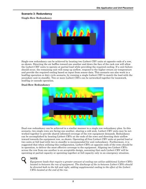
Scenario 3: Redundancy<br />
Single-Row Redundancy<br />
5<br />
Site <strong>Application</strong> and Unit Placement<br />
Single-row redundancy can be achieved by locating two <strong>Liebert</strong> <strong>CRV</strong> units at opposite ends of a row,<br />
as shown. Directing the air baffles toward one another and down the face of the rack row will allow<br />
the <strong>Liebert</strong> <strong>CRV</strong> units to operate at partial load while providing the required cooling. If a unit failure<br />
should occur, the remaining unit will ramp up airflow, respond to the higher return air temperature<br />
and provide the required cooling based on input from sensor data. This scenario can also work in a<br />
lead/lag operation or duty cycle scenario, by running a single <strong>Liebert</strong> <strong>CRV</strong> to match the load with the<br />
secondary unit in standby. Two or more <strong>Liebert</strong> <strong>CRV</strong>s can be networked together for teamwork,<br />
lead/lag or cascade operation.<br />
Dual-Row Redundancy<br />
Dual-row redundancy can be achieved in a similar manner to a single row redundancy plan. In this<br />
scenario, two single rows are facing one another, sharing a cold aisle. <strong>Liebert</strong> <strong>CRV</strong> units may be networked<br />
together to provide shared informed coverage of the row equipment demands. Redundancy<br />
can be accomplished by locating <strong>Liebert</strong> <strong>CRV</strong>s at the ends of the rows and directing their airflow<br />
inward towards the equipment row, as shown. Operating all four <strong>Liebert</strong> <strong>CRV</strong> units at partial load or<br />
two units at full load with two in standby is recommended for unit redundancy. Furthermore, it is<br />
suggested that when utilizing this configuration, <strong>Liebert</strong> <strong>CRV</strong>s at opposite ends of the rows should be<br />
in operation, to deliver the most effective coverage to the equipment. Aligning two <strong>Liebert</strong> <strong>CRV</strong>s<br />
across the row from one another is an acceptable design, assuming that each <strong>Liebert</strong> <strong>CRV</strong> will be<br />
operating at partial capacity or operating together at full capacity only in an emergency situation.<br />
NOTE<br />
Equipment loads that require a greater amount of cooling can utilize additional <strong>Liebert</strong> <strong>CRV</strong>s<br />
located in-between the row of equipment. The discharge of the in-between <strong>Liebert</strong> <strong>CRV</strong>s should<br />
be directed both to the left and right, adding supplemental cooling to the effect of the <strong>Liebert</strong><br />
<strong>CRV</strong>s located at the end of the row.