Hydrodynamic Torque Converter Type EL - Voith Turbo
Hydrodynamic Torque Converter Type EL - Voith Turbo
Hydrodynamic Torque Converter Type EL - Voith Turbo

Create successful ePaper yourself
Turn your PDF publications into a flip-book with our unique Google optimized e-Paper software.
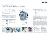
<strong>Hydrodynamic</strong> <strong>Torque</strong> <strong>Converter</strong> <strong>Type</strong> <strong>EL</strong><br />
Operating principle<br />
<strong>Torque</strong> converters are hydrodynamic<br />
transmissions, based on the<br />
”Foettinger Principle“. The heart of<br />
<strong>Voith</strong>‘s hydrodynamic torque converter<br />
is it‘s hydraulic circuit; consisting<br />
of pump, turbine and guide<br />
wheel with adjustable guide vanes.<br />
The mechanical energy of the motor<br />
is converted into kinetic fl uid energy<br />
through the pump wheel. In the turbine<br />
wheel, this kinetic energy is<br />
converted back into mechanical<br />
energy and transmitted to the output<br />
shaft. The adjustable guide vanes<br />
regulate the mass fl ow and thereby<br />
providing variable output speed.<br />
Customer benefi ts<br />
■ robust design with long service<br />
life<br />
■ low investment cost<br />
■ easy maintenance<br />
■ easy to install and to control<br />
■ wide operating range and<br />
accurate speed control<br />
■ wear free power transmission<br />
■ fast response time<br />
■ damping of torsional vibrations<br />
and shock loads<br />
■ suitable for a wide variety of<br />
environmental conditions, i.e.<br />
applications in tropical climate,<br />
the desert or low temperature<br />
zones, as well as in hazardous<br />
areas<br />
■ high reliability and availability<br />
■ unloaded motor start<br />
■ overload protection of motor<br />
■ no harmonic vibration problems<br />
■ excellent torsional vibration<br />
damping<br />
■ increased output torque for startup<br />
or emergency conditions
Design and Applications<br />
Design<br />
The <strong>EL</strong> type torque converter is a<br />
fully self supported unit. The rotating<br />
parts are supported in the closed, oil<br />
tight housing. Main motor and driven<br />
machine are connected to the torque<br />
converter via connecting couplings.<br />
The oil tank is integrated into the<br />
cast iron housing, the oil pump is<br />
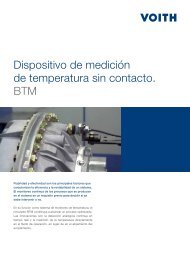
Controls and guide vane<br />
adjustment<br />
driven by the input shaft, providing<br />
the working and lube oil. The shafts<br />
are supported in anti-friction bearings.<br />
Guide vanes Pump wheel Turbine wheel<br />
The adjustable guide vanes can be<br />
controlled by a pneumatic, hydraulic<br />
or electric actuator, which receives<br />
an input signal of 4 – 20 mA or<br />
0.2 – 1 bar from the customer‘s<br />
master control system. The feedback<br />
signal, to incorporate the<br />
torque converter in a closed control<br />
loop, can be provided by switches or<br />
as a 4 – 20 mA signal.<br />
Guide vanes closed (L x = 0%) Guide vanes max. opened (L x = 100%)<br />
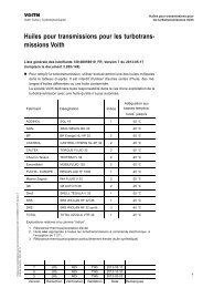
Input <strong>Torque</strong> / Speed Characteristics<br />
L x = 100%<br />
L x = 75%<br />
L x = 50%<br />
L x = 25%<br />
L x = 0%
Applications<br />
The torque converters of this series<br />
are variable-speed drives, especially<br />
developed for electric motors with<br />
constant speed (squirrel cage or induction<br />
motors) or diesel engines<br />
with limited regulating range. With<br />
the adjustable guide vanes, speed<br />
and torque can be controlled within<br />
a wide operating range. The unload-<br />
Output <strong>Torque</strong> / Speed Characteristics<br />
L x = Guide vane setting<br />
T P = Input torque<br />
T T = Output torque<br />
n P = Input speed<br />
n T = Output speed<br />
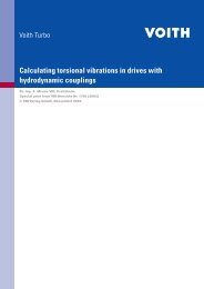
1 <strong>Torque</strong> converter<br />
2 Shaft driven gear pump<br />
3 Pressure relief valve<br />
4 Heat exchanger<br />
5 Oil fi lter<br />
6 Orifi ce<br />
ed motor start allows a smooth and<br />
controlled start of the driven machine.<br />
These torque converters are<br />
mainly used on constant torque applications<br />
e.g. displacer machines,<br />
working against a constant pressure<br />
at low and high speed settings, like<br />
reciprocating pumps, screw pumps<br />
or compressors as well as agitators,<br />
Simplifi ed longitudinal section of torque converter<br />
1 7 5 3 2 4<br />
6<br />
P & I Diagram Power chart<br />
9<br />
8<br />
1 Input shaft<br />
2 Pump wheel<br />
3 Turbine wheel<br />
4 Output shaft<br />
5 Adjustable guide vanes<br />
<strong>Converter</strong> input power P 1 [kW]<br />
2000<br />
1000<br />
600<br />
400<br />
200<br />
100<br />
60<br />
40<br />
20<br />
mixers, extruders or winches. The<br />
hydrodynamic principle of the torque<br />
converter provides a natural overload<br />
protection of the motor and the<br />
driven machine by dampening<br />
torque spikes, which increase the<br />
lifetime of the entire drive train.<br />
6 Guide vane adjustment<br />
mechanism<br />
7 Gear pump<br />
8 Pressure relief valve<br />
9 Oil reservoir<br />
<strong>EL</strong> 10<br />
<strong>EL</strong> 9<br />
<strong>EL</strong> 8<br />
<strong>EL</strong> 7<br />
<strong>EL</strong> 6<br />
<strong>EL</strong> 5<br />
<strong>EL</strong> 4<br />
<strong>EL</strong> 3<br />
10<br />
700 1000 1500 2000 2500 3000<br />
<strong>Converter</strong> input speed n1 [rpm]<br />
5
ø75 h6<br />
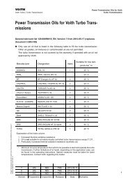
<strong>Voith</strong> <strong>Turbo</strong> GmbH & Co. KG<br />
Variable Speed Drives<br />
<strong>Voith</strong>str. 1<br />
74564 Crailsheim, Germany<br />
Tel. +49 7951 32 -261<br />
Fax +49 7951 32 -650<br />
vs.drives@voith.com<br />
www.variable-speed.com<br />
www.voithturbo.com<br />
<strong>Torque</strong> converter type <strong>EL</strong> 7 / 8 <strong>Torque</strong> converter type <strong>EL</strong> 9 / 10<br />
120<br />
870<br />
120<br />
ø75 h6<br />
max. 970<br />
340<br />
745<br />
ø95 h6<br />
150<br />
989<br />
150 ø95 h6<br />
max. 1015<br />
390<br />
760<br />
Cr 208 en 06.2006 1.000 aik / WF. Technical data and illustrations subject to change.