EN / ACS850 Quick Start-up Guide (Standard Control Program) - ABB
EN / ACS850 Quick Start-up Guide (Standard Control Program) - ABB
EN / ACS850 Quick Start-up Guide (Standard Control Program) - ABB
Create successful ePaper yourself
Turn your PDF publications into a flip-book with our unique Google optimized e-Paper software.
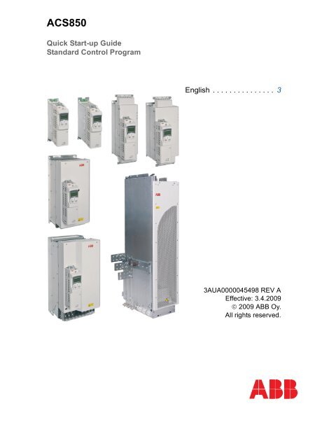
<strong>ACS850</strong><br />
<strong>Quick</strong> <strong>Start</strong>-<strong>up</strong> <strong>Guide</strong><br />
<strong>Standard</strong> <strong>Control</strong> <strong>Program</strong><br />
English . . . . . . . . . . . . . . . 3<br />
3AUA0000045498 REV A<br />
Effective: 3.4.2009<br />
© 2009 <strong>ABB</strong> Oy.<br />
All rights reserved.
<strong>ACS850</strong> drive manuals<br />
DRIVE HARDWARE MANUAL*<br />
<strong>ACS850</strong>-04 Drive Modules (1.1 to 45 kW) Hardware Manual – 3AUA0000045496 (English)<br />
<strong>ACS850</strong>-04 Drive Modules (55 to 160 kW, 75 to 200 hp) Hardware Manual – 3AUA0000045487 (English)<br />
<strong>ACS850</strong>-04 Drive Modules (200 to 500 kW, 250 to 600 hp) Hardware Manual – 3AUA0000026234 (English)<br />
DRIVE FIRMWARE MANUALS<br />
<strong>ACS850</strong> <strong>Standard</strong> <strong>Control</strong> <strong>Program</strong> Firmware Manual – 3AUA0000045497 (English).<br />
OPTION MANUALS<br />
<strong>ACS850</strong> <strong>Control</strong> Panel User’s <strong>Guide</strong> – 3AUA0000050277 (English)<br />
FIO-01 Digital I/O Extension User’s Manual* – 3AFE68784921 (English)<br />
FIO-11 Analog I/O Extension User’s Manual* – 3AFE68784930 (English)<br />
FIO-21 Analog I/O Extension User’s Manual* – 3AUA0000031061 (English)<br />
F<strong>EN</strong>-01 TTL Encoder Interface User’s Manual* – 3AFE68784603 (English)<br />
F<strong>EN</strong>-11 Absolute Encoder Interface User’s Manual* – 3AFE68784841 (English)<br />
F<strong>EN</strong>-21 Resolver Interface User’s Manual* – 3AFE68784859 (English)<br />
F<strong>EN</strong>-31 HTL Encoder Interface User’s Manual* – 3AUA0000031044 (English)<br />
*A multilingual quick installation guide is included with the delivery.
<strong>Quick</strong> <strong>Start</strong>-<strong>up</strong> <strong>Guide</strong> for <strong>ACS850</strong> with <strong>Standard</strong> <strong>Control</strong> <strong>Program</strong> 3<br />
<strong>Quick</strong> <strong>Start</strong>-<strong>up</strong> <strong>Guide</strong> for <strong>ACS850</strong> with <strong>Standard</strong><br />
<strong>Control</strong> <strong>Program</strong><br />
About this guide<br />
This guide contains the basic procedure that needs to be followed to start <strong>up</strong> an<br />
<strong>ACS850</strong> drive (with <strong>Standard</strong> <strong>Control</strong> <strong>Program</strong>). During the procedure, the drive is set<br />
<strong>up</strong> using the <strong>ACS850</strong> <strong>Control</strong> Panel.<br />
Note: Only the functions of the <strong>Control</strong> Panel needed during the procedure are<br />
described in the guide. For further information, refer to <strong>ACS850</strong> <strong>Control</strong> Panel User’s<br />
<strong>Guide</strong> (3AUA0000050277 [English]).<br />
Safety instructions<br />
WARNING! All electrical installation and maintenance work on the drive<br />
should be carried out by qualified electricians only.<br />
Never work on the drive, the braking chopper circuit, the motor cable or the motor<br />
when input power is applied to the drive. Always ensure by measuring that no voltage<br />
is actually present.
4 <strong>Quick</strong> <strong>Start</strong>-<strong>up</strong> <strong>Guide</strong> for <strong>ACS850</strong> with <strong>Standard</strong> <strong>Control</strong> <strong>Program</strong><br />
<strong>Start</strong>-<strong>up</strong> procedure<br />
Safety<br />
The start-<strong>up</strong> may only be carried out by a qualified electrician.<br />
The safety instructions must be followed during the start-<strong>up</strong> procedure. See the<br />
safety instructions on the first pages of the appropriate hardware manual.<br />
Check the installation. See the installation checklist in the appropriate hardware<br />
manual.<br />
Check that the starting of the motor does not cause any danger.<br />
De-co<strong>up</strong>le the driven machine if<br />
• there is a risk of damage in case of an incorrect direction of rotation, or<br />
• a normal ID run is required during the drive start-<strong>up</strong>, when the load torque is higher<br />
than 20% or the machinery is not able to withstand the nominal torque transient<br />
during the ID run.<br />
Power-<strong>up</strong>, control panel basics<br />
Connect the control panel to the drive using an<br />
appropriate Category 5E cable.<br />
Power <strong>up</strong> the drive. After a few moments, the panel<br />
shows the Output mode (right).<br />
Note: The Output mode display will alternate with<br />
“Alarm 2021 NO MOTOR DATA” until an assistant is<br />
launched later in the procedure.<br />
Switch to local control to ensure that external control<br />
LOC<br />
is disabled by pressing the REM key on the control<br />
panel. Local control is indicated by the text “LOC” on<br />
the top row on the display.<br />
The two boxes on the bottom row of the display<br />
indicate the function of the two soft keys and<br />
. The contents of the boxes depend on the<br />
visible menu choices.<br />
Press (M<strong>EN</strong>U) to access the Main menu.<br />
Within any menu, the desired selection is<br />
highlighted. Press the and keys to<br />
make a new choice; activate by pressing<br />
(<strong>EN</strong>TER).<br />
The Main menu is the starting point for the<br />
procedures described below.<br />
Adjusting parameter values<br />
REM<br />
0.00rpm<br />
0. 00 Hz<br />
0. 00 A<br />
0. 0 %<br />
DIR M<strong>EN</strong>U<br />
LOC<br />
0.00rpm<br />
0. 00 Hz<br />
0. 00 A<br />
0. 0 %<br />
DIR M<strong>EN</strong>U<br />
LOC<br />
MAIN M<strong>EN</strong>U<br />
PARAMETERS<br />
ASSISTANTS<br />
CHANGED PAR<br />
1<br />
EXIT <strong>EN</strong>TER<br />
Notes:<br />
• At any point, press (CANCEL or EXIT) to return to the previous level.<br />
• By default, not all parameters are visible. Set parameter 16.15 Menu set sel to Load<br />
long to make all parameters visible.
<strong>Quick</strong> <strong>Start</strong>-<strong>up</strong> <strong>Guide</strong> for <strong>ACS850</strong> with <strong>Standard</strong> <strong>Control</strong> <strong>Program</strong> 5<br />
To adjust a parameter within an assistant:<br />
• Use the and keys to adjust the setting. Press SAVE to accept the<br />
setting shown and to proceed to the next parameter.<br />
To adjust a parameter at any other time:<br />
• In the Main menu, highlight PARAMETERS and press (<strong>EN</strong>TER).<br />
• Use and to browse the list of parameter gro<strong>up</strong>s. Highlight the desired<br />
gro<strong>up</strong> and press (SEL) to display the parameters within that gro<strong>up</strong>.<br />
• Highlight a parameter and press (EDIT) to adjust the setting.<br />
• Use and to adjust the setting. Press SAVE to accept the setting<br />
shown. Press EXIT twice to return to the Main menu.<br />
Notes for more complicated edits:<br />
• With parameters that define a digital source, the setting Const can be used to fix the<br />
value to constant 1 (C.TRUE) or 0 (C.FALSE).<br />
• With parameters that define an analog or digital source, the setting Pointer can be<br />
used to freely choose any parameter value (analog) or a specific bit of a packed<br />
boolean parameter (digital) as the source:<br />
• With an analog source, the parameter gro<strong>up</strong> LOC PAR EDIT<br />
and parameter index are specified. After<br />
selecting the gro<strong>up</strong>, press NEXT to move to the<br />
index setting.<br />
The text below the cursor reflects the current<br />
setting.<br />
After setting the index, press SAVE to accept<br />
the value. Press CANCEL at any point to<br />
discard any changes and to return to the<br />
parameter list.<br />
1501 AO1 src<br />
P.01.06<br />
0106 Motor torque<br />
CANCEL SAVE<br />
• With a digital source, the parameter gro<strong>up</strong>, LOC PAR EDIT<br />
parameter index, and bit number are specified.<br />
After setting an item, press NEXT to move to<br />
the next.<br />
The text below the cursor reflects the current<br />
setting.<br />
After the bit number is set, press SAVE to<br />
accept the value. Press CANCEL at any point<br />
to discard any changes and to return to the<br />
parameter list.<br />
1002 Ext1 start in1<br />
P.02.01.00<br />
0201 DI status<br />
CANCEL NEXT<br />
Changing the language<br />
By default, the language of the text shown is English. If desired, the language can be<br />
changed as follows.<br />
In the Main menu, make sure PARAMETERS is<br />
highlighted, and press <strong>EN</strong>TER.<br />
LOC<br />
MAIN M<strong>EN</strong>U<br />
PARAMETERS<br />
ASSISTANTS<br />
CHANGED PAR<br />
1<br />
EXIT <strong>EN</strong>TER
6 <strong>Quick</strong> <strong>Start</strong>-<strong>up</strong> <strong>Guide</strong> for <strong>ACS850</strong> with <strong>Standard</strong> <strong>Control</strong> <strong>Program</strong><br />
Navigate to parameter gro<strong>up</strong> 99 <strong>Start</strong>-<strong>up</strong> data and<br />
press SEL. Note that the list will wrap around in<br />
either direction between gro<strong>up</strong>s 99 and 01 – it is<br />
quicker to press for gro<strong>up</strong> 99.<br />
Make sure parameter “9901 Language” is<br />
highlighted and press EDIT.<br />
Select the desired language and press SAVE.<br />
Press EXIT twice to return to the Main menu.<br />
Firmware assistants<br />
The start-<strong>up</strong> procedures described below make use of firmware assistants. These are<br />
routines that guide the user through the essential parameter settings.<br />
1 – Application macro selection<br />
In the Main menu, highlight ASSISTANTS and press<br />
<strong>EN</strong>TER.<br />
Highlight Firmware assistants and press SEL.<br />
Highlight Application Macro and press OK.<br />
LOC PAR GROUPS 99<br />
99 <strong>Start</strong>-<strong>up</strong> data<br />
01 Actual values<br />
02 I/O values<br />
03 <strong>Control</strong> values<br />
04 Appl values<br />
EXIT SEL<br />
LOC<br />
PARAMETERS<br />
9901 Language<br />
English<br />
9904 Motor type<br />
9905 Motor ctrl mode<br />
9906 Mot nom current<br />
EXIT EDIT<br />
LOC PAR EDIT<br />
9901 Language<br />
Deutsch<br />
[0407 hex]<br />
CANCEL SAVE<br />
LOC MAIN M<strong>EN</strong>U<br />
PARAMETERS<br />
ASSISTANTS<br />
CHANGED PAR<br />
1<br />
EXIT <strong>EN</strong>TER<br />
LOC ASSISTANTS 1<br />
Firmware assistants<br />
Application assistant<br />
EXIT SEL<br />
LOC<br />
CHOICE<br />
Select assistant<br />
Application Macro<br />
Motor Set-<strong>up</strong><br />
EXIT OK
<strong>Quick</strong> <strong>Start</strong>-<strong>up</strong> <strong>Guide</strong> for <strong>ACS850</strong> with <strong>Standard</strong> <strong>Control</strong> <strong>Program</strong> 7<br />
Application macros are pre-defined parameter<br />
settings that can be used as a basis for user<br />
applications. The following macros are available:<br />
• Factory (for speed control applications where a<br />
simple start/stop interface is required)<br />
• Hand/Auto (for speed control applications where<br />
two external control devices are used)<br />
• PID control (for process control applications<br />
such as closed-loop pressure, level or flow control<br />
systems)<br />
• Torque control (for torque and/or speed control<br />
of motor)<br />
• Sequential control (for speed control<br />
applications in which multiple constant speeds<br />
and acceleration/deceleration ramps are needed<br />
and are sequenced).<br />
More information on the macros is available in the<br />
Firmware Manual.<br />
Highlight one of the macros and press OK.<br />
Parameter defaults for the macro<br />
are applied.<br />
After the text “Done OK” appears on the control panel, press OK to complete the<br />
firmware assistant.<br />
2 – Motor set-<strong>up</strong><br />
Ensure you have the motor nameplate and encoder data (if needed) at hand.<br />
In the Main menu, highlight ASSISTANTS and press<br />
<strong>EN</strong>TER.<br />
Highlight Firmware assistants and press SEL.<br />
Highlight Motor Set-<strong>up</strong> and press OK.<br />
The assistant will guide you through the motor set<strong>up</strong>.<br />
Select the motor type, AM (asynchronous squirrel<br />
cage AC motor) or PMSM (permanent magnet<br />
synchronous motor).<br />
LOC MAIN M<strong>EN</strong>U<br />
PARAMETERS<br />
ASSISTANTS<br />
CHANGED PAR<br />
1<br />
EXIT <strong>EN</strong>TER<br />
LOC ASSISTANTS 1<br />
Firmware assistants<br />
Application assistant<br />
EXIT SEL<br />
LOC<br />
CHOICE<br />
Select assistant<br />
Application Macro<br />
Motor Set-<strong>up</strong><br />
EXIT OK<br />
99.04 Motor type
8 <strong>Quick</strong> <strong>Start</strong>-<strong>up</strong> <strong>Guide</strong> for <strong>ACS850</strong> with <strong>Standard</strong> <strong>Control</strong> <strong>Program</strong><br />
Select the motor control mode. DTC is suitable for<br />
most cases.<br />
Scalar mode is recommended if<br />
• the nominal current of the motor is less than 1/6<br />
of the nominal current of the drive,<br />
• the drive is used for test purposes with no motor<br />
connected, or<br />
• the drive controls multiple motors and the number<br />
of motors connected is variable.<br />
Enter the motor data from the motor nameplate.<br />
Asynchronous motor nameplate example:<br />
6312/C3<br />
<strong>ABB</strong> Motors<br />
M2AA 200 MLA 4<br />
V Hz kW r/min A cos IA/IN<br />
690 Y 50 30 1475 32.5 0.83<br />
400 D 50 30 1475 56 0.83<br />
660 Y 50 30 1470 34 0.83<br />
380 D 50 30 1470 59 0.83<br />
415 D 50 30 1475 54 0.83<br />
440 D 60 35 1770 59 0.83<br />
Cat. no 3GAA 202 001 - ADA<br />
t 3 motor<br />
IEC 200 M/L 55<br />
No<br />
Ins.cl. F IP 55<br />
E/s<br />
6210/C3<br />
180<br />
IEC 34-1<br />
Permanent magnet motor nameplate example:<br />
3 ~ motor M2BJ 280SMB 10 B3<br />
S1 SPEC INSUL.<br />
JK-21640-1<br />
V Hz kW<br />
400 D<br />
50<br />
<strong>ABB</strong> Motors<br />
55<br />
r/min<br />
600<br />
No 3424522<br />
Ins.cl. F IP 55<br />
A<br />
103<br />
cos �<br />
0.97<br />
IA/IN<br />
Prod. code 2GBJ285220-ADA405445477<br />
6316/C3 6316/C3 630kg<br />
IEC 34-1<br />
• motor nominal current<br />
Allowed range: approximately 1/6 × I2n … 2 × I2n of<br />
the drive (0…2 × I2nd if parameter 99.05 Motor ctrl<br />
mode = Scalar).<br />
t E/s<br />
99.05 Motor ctrl mode<br />
Note: Set the motor data to<br />
exactly the same value as on the<br />
motor nameplate. For example, if<br />
the motor nominal speed is 1470<br />
rpm on the nameplate, setting the<br />
value of parameter 99.09 Mot<br />
nom speed to 1500 rpm results in<br />
incorrect operation of the drive.<br />
If D (delta) data is chosen, then<br />
connect the motor in delta.<br />
If Y (star) data is selected, then<br />
connect the motor in star.<br />
99.06 Mot nom current
<strong>Quick</strong> <strong>Start</strong>-<strong>up</strong> <strong>Guide</strong> for <strong>ACS850</strong> with <strong>Standard</strong> <strong>Control</strong> <strong>Program</strong> 9<br />
• motor nominal voltage<br />
Allowed range: 1/6 × UN … 2 × UN of the drive. (UN<br />
refers to the highest voltage in each nominal voltage<br />
range).<br />
With permanent magnet motors, the nominal<br />
voltage is the BackEMF voltage (at motor nominal<br />
speed). If the voltage is given as voltage per rpm,<br />
e.g. 60 V per 1000 rpm, the voltage for 3000 rpm<br />
nominal speed is 3 × 60 V = 180 V.<br />
Note that the nominal voltage is not equal to the<br />
equivalent DC motor voltage (E.D.C.M.) value given<br />
by some motor manufacturers. The nominal voltage<br />
can be calculated by dividing the E.D.C.M. voltage<br />
by 1.7 (= square root of 3).<br />
• motor nominal frequency<br />
With permanent magnet motor: If the frequency is<br />
not given on the motor nameplate, it has to be<br />
calculated using the following formula:<br />
f = n × p /60<br />
where p = number of pole pairs, n = motor nominal<br />
speed.<br />
99.07 Mot nom voltage<br />
99.08 Mot nom freq<br />
• motor nominal speed 99.09 Mot nom speed<br />
• motor nominal power 99.10 Mot nom power<br />
The following motor data parameters can be set to improve control accuracy. If not<br />
known, set the values to 0.<br />
• motor nominal cosϕ (not applicable for permanent 99.11 Mot nom cosfii<br />
magnet motors)<br />
• motor nominal shaft torque 99.12 Mot nom torque<br />
The following parameters define operation limits to protect the driven equipment.<br />
• maximum speed<br />
This value should be higher than 55% of the motor<br />
nominal speed defined earlier.<br />
• minimum speed<br />
This value should be less than or equal to 0 rpm.<br />
• maximum current<br />
This value should be equal to or higher than the<br />
motor nominal current defined earlier.<br />
• maximum torque<br />
This value should be at least 100% of motor nominal<br />
torque defined earlier.<br />
20.01 Maximum speed<br />
20.02 Minimum speed<br />
20.05 Maximum current<br />
20.07 Maximum torque1<br />
• minimum torque 20.08 Minimum torque1
10 <strong>Quick</strong> <strong>Start</strong>-<strong>up</strong> <strong>Guide</strong> for <strong>ACS850</strong> with <strong>Standard</strong> <strong>Control</strong> <strong>Program</strong><br />
The question “Do you want to perform id-run now?” is displayed. The ID run<br />
(identification run) will identify the characteristics of the motor for optimum control.<br />
If you do not wish to perform the ID run at this point, select No to complete the Motor<br />
Set-<strong>up</strong> firmware assistant. Proceed to section 3 – <strong>Start</strong>/Stop configuration.<br />
If you wish to perform the ID run, continue with the following steps BEFORE selecting<br />
Yes.<br />
WARNING! With Normal or Reduced ID run the motor will run at <strong>up</strong> to<br />
approximately 50…100% of the nominal speed during the ID run. <strong>EN</strong>SURE<br />
THAT IT IS SAFE TO RUN THE MOTOR BEFORE PERFORMING THE ID<br />
RUN!<br />
Check the direction of rotation of the motor. During<br />
the run (Normal or Reduced), the motor will rotate in<br />
the forward direction.<br />
Ensure the Safe Torque Off and emergency stop<br />
circuits (if present) are closed.<br />
Select Yes and press OK.<br />
Select the ID run method.<br />
The ID run will be performed at the next start of the<br />
drive.<br />
NORMAL ID run should be selected whenever<br />
possible.<br />
Note: The driven machinery must be de-co<strong>up</strong>led<br />
from the motor with Normal ID run:<br />
• if the load torque is higher than 20%, or<br />
• if the machinery is not able to withstand the<br />
nominal torque transient during the ID run.<br />
The REDUCED ID run should be selected instead of<br />
the Normal ID run if the mechanical losses are<br />
higher than 20%, i.e. the motor cannot be<br />
de-co<strong>up</strong>led from the driven equipment, or full flux is<br />
required to keep the motor brake open (conical<br />
motor).<br />
When drive output phases<br />
U2, V2 and W2 are connected<br />
to the corresponding<br />
motor terminals:<br />
99.13 Idrun mode<br />
forward<br />
direction<br />
reverse<br />
direction
<strong>Quick</strong> <strong>Start</strong>-<strong>up</strong> <strong>Guide</strong> for <strong>ACS850</strong> with <strong>Standard</strong> <strong>Control</strong> <strong>Program</strong> 11<br />
The STANDSTILL ID run should be selected only if<br />
the Normal or Reduced ID run is not possible due to<br />
the restrictions caused by the connected mechanics<br />
(e.g. with lift or crane applications).<br />
Notes:<br />
• The motor shaft must NOT be locked and the load<br />
torque must be < 20% during Normal or Reduced<br />
ID run. With permanent magnet motor this<br />
restriction also applies when Standstill ID run is<br />
selected.<br />
• Mechanical brake is not opened by the logic for<br />
the ID run.<br />
• The ID run cannot be performed if parameter<br />
99.05 Motor ctrl mode = Scalar.<br />
<strong>Start</strong> the motor (by pressing the START button) to<br />
activate the ID run.<br />
ID run is indicated by alarm ID-RUN on the panel<br />
display.<br />
The 7-segment display on the drive will flash the<br />
alarm code A-2008 (ID-RUN) while the ID run is in<br />
progress. After the ID run, the display will return to<br />
the “drive stopped” state.<br />
Alarm: ID-RUN<br />
After the text “Done OK” appears on the control panel, press OK to complete the<br />
firmware assistant.<br />
3 – <strong>Start</strong>/Stop configuration<br />
In the Main menu, highlight ASSISTANTS and press<br />
<strong>EN</strong>TER.<br />
Highlight Firmware assistants and press SEL.<br />
Highlight <strong>Start</strong>/Stop <strong>Control</strong> and press OK.<br />
The following parameters will be set.<br />
Note: Depending on the selections you make, the<br />
routine may skip some of the parameters listed<br />
below.<br />
LOC MAIN M<strong>EN</strong>U<br />
PARAMETERS<br />
ASSISTANTS<br />
CHANGED PAR<br />
1<br />
EXIT <strong>EN</strong>TER<br />
LOC ASSISTANTS 1<br />
Firmware assistants<br />
Application assistant<br />
EXIT SEL<br />
LOC<br />
CHOICE<br />
Select assistant<br />
Motor Set-<strong>up</strong>Motor<br />
<strong>Start</strong>/Stop <strong>Control</strong><br />
EXIT OK
12 <strong>Quick</strong> <strong>Start</strong>-<strong>up</strong> <strong>Guide</strong> for <strong>ACS850</strong> with <strong>Standard</strong> <strong>Control</strong> <strong>Program</strong><br />
Select the start/stop function and signal sources for<br />
external control location 1 (EXT1). First, program<br />
parameter 10.01 (start function), then 10.02 and<br />
10.03 to choose the sources of the start signal.<br />
The choices for parameter 10.01 are:<br />
In1: The signal defined in parameter 10.02 is the<br />
source for the start signal (0 = Stop, 1 = <strong>Start</strong>).<br />
3-wire: <strong>Start</strong>/Stop commands are determined on the<br />
basis of the two sources selected by parameters<br />
10.02 and 10.03.<br />
State of source 1 State of source 2 Command<br />
(via par. 10.02) (via par. 10.03)<br />
0 -> 1 1 <strong>Start</strong><br />
Any 1 -> 0 Stop<br />
Any 0 Stop<br />
In1F In2R: The signal defined in parameter 10.02<br />
starts the drive in the forward direction, and the<br />
signal defined in 10.03 will start the drive in reverse.<br />
In1St In2Dir: The signal defined in parameter 10.01<br />
will start the drive (0 = Stop, 1 = <strong>Start</strong>). The signal<br />
defined in 10.03 will change the motor direction<br />
(0 = forward, 1 = reverse).<br />
Select the start/stop function and signal sources for<br />
external control location 2 (EXT2).<br />
The selections are as with EXT1 above.<br />
Define the signal source to switch between external<br />
control locations EXT1 and EXT2 (0 = EXT1, 1 =<br />
EXT2).<br />
Select the motor start function.<br />
Automatic is the best all-round setting that also<br />
enables flying start (starting when the motor is<br />
rotating).<br />
Fast involves pre-magnetization of the motor and<br />
should be selected if a high break-away torque is<br />
required.<br />
Const time should be selected if a constant premagnetization<br />
time is required. The time is set by<br />
parameter 11.02 DC-magn time.<br />
Select the stop mode.<br />
Coast: The power to the motor is cut off. The motor<br />
is left to coast to a stop.<br />
Ramp: The motor is stopped by decelerating along<br />
the active deceleration ramp (to be defined later).<br />
10.01 Ext1 start func<br />
10.02 Ext1 start in1<br />
10.03 Ext1 start in2<br />
10.04 Ext2 start func<br />
10.05 Ext2 start in1<br />
10.06 Ext2 start in2<br />
12.01 Ext1/Ext2 sel<br />
11.01 <strong>Start</strong> mode<br />
11.03 Stop mode
<strong>Quick</strong> <strong>Start</strong>-<strong>up</strong> <strong>Guide</strong> for <strong>ACS850</strong> with <strong>Standard</strong> <strong>Control</strong> <strong>Program</strong> 13<br />
Select the source of the run enable signal.<br />
If the signal is switched off, the drive will not start, or<br />
coasts to stop if running. 1 = Run enable signal on.<br />
Select the source of the emergency stop OFF3<br />
signal.<br />
If the signal is removed (in other words, changes to<br />
0), the drive will stop along the emergency stop<br />
ramp (defined by parameter 22.12 Em stop time).<br />
10.11 Run enable<br />
10.13 Em stop off3<br />
After the text “Done OK” appears on the control panel, press OK to complete the<br />
firmware assistant.<br />
4 – Reference selection<br />
In the Main menu, highlight ASSISTANTS and press<br />
<strong>EN</strong>TER.<br />
Highlight Firmware assistants and press SEL.<br />
Highlight Reference select and press OK.<br />
The following parameters will be set.<br />
Note: Depending on the selections you make, the<br />
routine may skip some of the parameters listed<br />
below.<br />
Select the control mode for external control<br />
locations EXT1 and EXT2.<br />
Speed: Speed control.<br />
Torque: Torque control.<br />
Min, Max, Add: Torque reference and speed<br />
controller output are compared and the<br />
mathematical function is applied (smaller, greater,<br />
addition).<br />
Depending on the selections, the speed or torque<br />
reference source (or both) is defined next.<br />
LOC MAIN M<strong>EN</strong>U<br />
PARAMETERS<br />
ASSISTANTS<br />
CHANGED PAR<br />
1<br />
EXIT <strong>EN</strong>TER<br />
LOC ASSISTANTS 1<br />
Firmware assistants<br />
Application assistant<br />
EXIT SEL<br />
LOC<br />
CHOICE<br />
Select assistant<br />
<strong>Start</strong>/Stop <strong>Control</strong><br />
Reference select<br />
EXIT OK<br />
12.03 Ext1 ctrl mode<br />
12.05 Ext2 ctrl mode
14 <strong>Quick</strong> <strong>Start</strong>-<strong>up</strong> <strong>Guide</strong> for <strong>ACS850</strong> with <strong>Standard</strong> <strong>Control</strong> <strong>Program</strong><br />
Speed reference set-<strong>up</strong><br />
Choose the number of constant speeds (if any) to use.<br />
If you select any constant speeds, you are asked if the start direction should affect the<br />
constant speed direction.<br />
No: The sign of the constant speed directly determines the running direction when the<br />
constant speed is activated.<br />
Yes: The sign of the constant speed is multiplied by the value of the Direction signal to<br />
determine the running direction when the constant speed is activated.<br />
You are now asked if each constant speed selector should activate one constant speed.<br />
No: Constant speeds 1…7 are activated by the sources selected by parameters 26.02,<br />
26.03 and 26.04 as follows:<br />
Source defined by<br />
par. 26.02<br />
Source defined by<br />
par. 26.03<br />
Source defined by<br />
par. 26.04<br />
Yes: Constant speeds 1…3 are activated by the sources selected by parameters 26.02,<br />
26.03 and 26.04 respectively.<br />
Set the constant speed selector sources. 26.02 Const speed sel1<br />
26.03 Const speed sel2<br />
26.04 Const speed sel3<br />
Enter the constant speeds. 26.06 Const speed1…<br />
Select the source of the speed reference signal. 21.01 Speed ref1 sel<br />
Define the absolute minimum limit for the speed<br />
reference. This limit applies for both the positive and<br />
negative ranges.<br />
Constant speed active<br />
0 0 0 None<br />
1 0 0 Constant speed 1<br />
0 1 0 Constant speed 2<br />
1 1 0 Constant speed 3<br />
0 0 1 Constant speed 4<br />
1 0 1 Constant speed 5<br />
0 1 1 Constant speed 6<br />
1 1 1 Constant speed 7<br />
21.09 SpeedRef min abs
<strong>Quick</strong> <strong>Start</strong>-<strong>up</strong> <strong>Guide</strong> for <strong>ACS850</strong> with <strong>Standard</strong> <strong>Control</strong> <strong>Program</strong> 15<br />
Define the speed scaling used for the acceleration/<br />
deceleration times. Define the acceleration/<br />
deceleration times.<br />
The diagram below shows the effect of parameter<br />
19.01 Speed scaling on the acceleration/<br />
deceleration times.<br />
0<br />
Speed<br />
19.01<br />
Acc. Dec.<br />
22.02 or<br />
22.04<br />
Note: Acceleration/deceleration times may be<br />
automatically extended by the existing torque limits.<br />
Select the source to switch between acceleration/<br />
deceleration ramp pairs 1 and 2.<br />
0 = Acceleration time 1/Deceleration time 1 are in<br />
force, 1 = Acceleration time 2/Deceleration time 2<br />
are in force.<br />
Torque reference set-<strong>up</strong><br />
22.03 or<br />
22.05<br />
Time<br />
19.01 Speed scaling<br />
22.02 Acc time1<br />
22.04 Acc time2<br />
22.03 Dec time1<br />
22.05 Dec time2<br />
22.01 Acc/Dec sel<br />
Select the source of the torque reference signal. 24.01 Torq ref1 sel<br />
Define the maximum and minimum torque<br />
references.<br />
Define the times for the torque reference to increase<br />
from zero to nominal motor torque (ramp <strong>up</strong>) and<br />
vice versa (ramp down).<br />
24.03 Maximum torq ref<br />
24.04 Minimum torq ref<br />
24.06 Torq ramp <strong>up</strong><br />
24.07 Torq ramp down
16 <strong>Quick</strong> <strong>Start</strong>-<strong>up</strong> <strong>Guide</strong> for <strong>ACS850</strong> with <strong>Standard</strong> <strong>Control</strong> <strong>Program</strong><br />
Analog input AI1/AI2 set-<strong>up</strong> (if either is selected as speed or torque reference source)<br />
Define the filter time constant for the analog input. 13.01 AI1 filt time or<br />
%<br />
100<br />
Unfiltered signal<br />
13.06 AI2 filt time<br />
63<br />
T<br />
O = I × (1 - e -t/T )<br />
I = filter input (step)<br />
O = filter output<br />
t = time<br />
T = filter time constant<br />
Define the maximum and minimum values for the<br />
analog input.<br />
Define the scaled values that correspond to the<br />
maximum and minimum values defined at the<br />
previous step. This is useful if full speed is required<br />
at lower analog input values.<br />
13.03/13.08<br />
13.04/13.09<br />
Filtered signal<br />
AI (scaled)<br />
13.05/13.10<br />
13.02 AI1 max or<br />
13.07 AI2 max<br />
13.03 AI1 min or<br />
13.08 AI2 min<br />
13.04 AI1 max scale or<br />
13.09 AI2 max scale<br />
13.05 AI1 min scale or<br />
13.10 AI2 min scale<br />
After the text “Done OK” appears on the control panel, press OK to complete the<br />
firmware assistant and the start-<strong>up</strong> procedure.<br />
t<br />
13.02/13.07<br />
AI (mA/V)
Further information<br />
Product and service inquiries<br />
Address any inquiries about the product to your local <strong>ABB</strong> representative, quoting the<br />
type designation and serial number of the unit in question. A listing of <strong>ABB</strong> sales,<br />
s<strong>up</strong>port and service contacts can be found by navigating to www.abb.com/drives and<br />
selecting Sales, S<strong>up</strong>port and Service network.<br />
Product training<br />
For information on <strong>ABB</strong> product training, navigate to www.abb.com/drives and select<br />
Training courses.<br />
Providing feedback on <strong>ABB</strong> Drives manuals<br />
Your comments on our manuals are welcome. Go to www.abb.com/drives and select<br />
Document Library – Manuals feedback form (LV AC drives).<br />
Document library on the Internet<br />
You can find manuals and other product documents in PDF format on the Internet. Go<br />
to www.abb.com/drives and select Document Library. You can browse the library or<br />
enter selection criteria, for example a document code, in the search field.
<strong>ABB</strong> Oy<br />
AC Drives<br />
P.O. Box 184<br />
FI-00381 HELSINKI<br />
FINLAND<br />
Telephone +358 10 22 11<br />
Fax +358 10 22 22681<br />
Internet http://www.abb.com<br />
<strong>ABB</strong> Inc.<br />
Automation Technologies<br />
Drives & Motors<br />
16250 West Glendale Drive<br />
New Berlin, WI 53151 USA<br />
Telephone 262 785-3200<br />
800-HELP-365<br />
Fax 262 780-5135<br />
<strong>ABB</strong> Beijing Drive Systems Co. Ltd.<br />
No. 1, Block D, A-10 Jiuxianqiao Beilu<br />
Chaoyang District<br />
Beijing, P.R. China, 100015<br />
Telephone +86 10 5821 7788<br />
Fax +86 10 5821 7618<br />
Internet http://www.abb.com<br />
3AUA0000045498 REV A / <strong>EN</strong><br />
EFFECTIVE: 3.4.2009


