in PDF Format - Embedded-Control-Europe.com
in PDF Format - Embedded-Control-Europe.com
in PDF Format - Embedded-Control-Europe.com

You also want an ePaper? Increase the reach of your titles
YUMPU automatically turns print PDFs into web optimized ePapers that Google loves.
Th<strong>in</strong>k<strong>in</strong>g TI?<br />
Texas Instruments’ <strong>in</strong>novative products help customers meet real-world signal process<strong>in</strong>g requirements.<br />
Click on the videos below to learn about some of TI’s latest products.<br />
STELLARIS<br />
Stellaris Robotic Evaluation<br />
Board With Micrium’s uC/OS-III<br />
Download the Stellaris ® ARM ®<br />
Cortex -M3 Microcontrollers Brochure<br />
Download the Stellaris White Paper<br />
“Get to Work <strong>in</strong> 10 M<strong>in</strong>utes”<br />
Learn more about Stellaris ® ARM ®<br />
Cortex-M3-based MCUs<br />
Stellaris for Wireless Connectivity Solutions<br />
Learn more about Stellaris Wireless<br />
Order a Stellaris Kit<br />
C2000<br />
Gett<strong>in</strong>g started with the high voltage<br />
motor control + PFC<br />
Download the Motor <strong>Control</strong> Solutions Guide<br />
Learn more about Digital Motor <strong>Control</strong><br />
High-Performance Analog >>Your Way and the platform bar are trademarks of Texas Instruments. © 2010 TI<br />
MSP430<br />
Discover the benefits of MSP430F5xx<br />
Ultra-Low-Power Microcontrollers<br />
Download the MSP430x5xx/MSP430x6xx<br />
Family User Guide<br />
Learn more about F5xx series<br />
Learn more about MSP430 MCUs<br />
DSPS<br />
AM389x Sitara ARM ® MPU<br />
Download the DSPS White Paper<br />
“Maximiz<strong>in</strong>g the Power of ARM with DSP”<br />
Learn more about AM389x<br />
Order a sample of AM3892<br />
www.ti.<strong>com</strong>
Tools & Software<br />
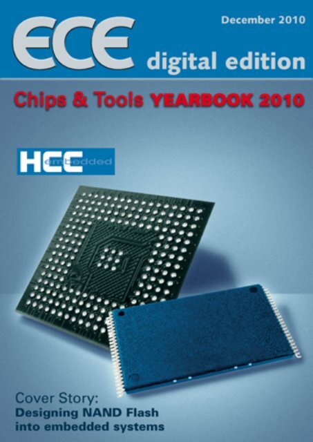
Cover Photo<br />
HCC-<strong>Embedded</strong><br />
CONTENTS<br />
Design<strong>in</strong>g NAND Flash<br />
<strong>in</strong>to embedded systems 4<br />
Agile methods and practices<br />
for embedded systems development 6<br />
Analys<strong>in</strong>g and optimiz<strong>in</strong>g the tim<strong>in</strong>g<br />
of a deeply embedded application 10<br />
W<strong>in</strong>dows <strong>Embedded</strong>:<br />
Enabl<strong>in</strong>g Connectivity 14<br />
Anti-piracy protection for<br />
embedded systems 15<br />
Microcontrollers<br />
Motor control <strong>in</strong> air conditioners with<br />
dual sensorless FOC and active PFC 18<br />
ARM-based K<strong>in</strong>etis MCUs and the<br />
future of microcontroller technology 22<br />
Comb<strong>in</strong><strong>in</strong>g ARM CPU, FPGA and<br />
analog functions <strong>in</strong> a s<strong>in</strong>gle chip 25<br />
Optimis<strong>in</strong>g LED light<strong>in</strong>g performance<br />
and efficiency with small MCUs 28<br />
Will touch sensors work properly<br />
even with hands <strong>in</strong> various gloves? 30<br />
Smart Meter<strong>in</strong>g<br />
Complete solutions for <strong>in</strong>telligent<br />
meter<strong>in</strong>g systems 33<br />
Smart meters give endless opportunity<br />
to transform energy usage 35<br />
Low-power wireless protocols for<br />
the green energy market 38<br />
3 December 2010
TOOLS & SOFTWARE<br />
Design<strong>in</strong>g NAND Flash<br />
<strong>in</strong>to embedded systems<br />
By Dave Hughes, HCC-<strong>Embedded</strong><br />
The benefits of a good design<br />
<strong>in</strong>corporat<strong>in</strong>g the latest NAND<br />
flash are truly stunn<strong>in</strong>g when<br />
viewed <strong>in</strong> any historical<br />
perspective: very large scale,<br />
high performance storage <strong>in</strong> a<br />
solid state device at relatively<br />
low cost. Moore’s Law is just<br />
not up to the job when it<br />
<strong>com</strong>es to progress <strong>in</strong> NAND<br />
flash. The only catch is that to<br />
get adequate reliability the<br />
details of the design must be<br />
well understood.<br />
n The use of NAND flash <strong>in</strong> embedded systems<br />
is one of the strongest trends <strong>in</strong> the <strong>in</strong>dustry.<br />
Some forecasts estimate that 2.5 billion NAND<br />
devices will be sold this year, with predictions<br />
of substantial year-on-year growth over the<br />
<strong>com</strong><strong>in</strong>g years. NAND flash has many advantages<br />
for embedded systems; high-volume storage at<br />
low cost, very fast access times, and very fast<br />
erase times make them ideal candidates for<br />
thousands of applications. But this feature set<br />
does not <strong>com</strong>e without a cost; the devices are<br />
relatively <strong>com</strong>plex to use and require a deeper<br />
understand<strong>in</strong>g than more conventional memory<br />
devices. The major players <strong>in</strong> the <strong>in</strong>dustry are<br />
very much focused on supply<strong>in</strong>g their ma<strong>in</strong><br />
customers: manufacturers of SSDs, USB drives,<br />
Flash cards, and Mobile phones – <strong>in</strong>deed anyone<br />
who buys these devices <strong>in</strong> huge quantities.<br />
This means that when designers of embedded<br />
devices are research<strong>in</strong>g the field, they must<br />
consider what is really available to them; the<br />
latest and greatest is probably reserved for certa<strong>in</strong><br />
target customers. In any case for these<br />
customers they are sold on reels <strong>in</strong> quantities<br />
that may be unrealistic for lower volume<br />
embedded designs.<br />
NAND Flash Overview<br />
All NAND flash is arranged as a set of blocks<br />
that are further subdivided <strong>in</strong>to pages. Each<br />
page consists of a data area that has a number<br />
of bytes equal to a power of 2, as well as an<br />
additional set of bytes – the spare area that<br />
may be considered as a scratch pad for system<br />
ma<strong>in</strong>tenance. As with all flash the block must<br />
be erased before pages can be written. Most of<br />
the latest NAND flash devices also have<br />
additional restriction that pages may only be<br />
programmed <strong>in</strong>crementally and these pages<br />
must be programmed <strong>in</strong>crementally with<strong>in</strong><br />
the block. The spare area has three primary<br />
functions <strong>in</strong> most NAND flash system designs:<br />
n To store bad block <strong>in</strong>formation<br />
n To store error correction codes<br />
n To store meta-data for management<br />
of the flash translation layer<br />
It is important to note that all the bits <strong>in</strong> a<br />
NAND device are subject to failure, and that<br />
bits of the spare area are just as likely to fail as<br />
bits <strong>in</strong> the data area. Therefore, any error correction<br />
algorithm must allow for corrupt bits<br />
<strong>in</strong> the stored ECC, <strong>in</strong> the meta-data, and <strong>in</strong><br />
any other data that are stored <strong>in</strong> the spare area.<br />
NAND size parameters have been grow<strong>in</strong>g rapidly.<br />
Pages have grown from 512bytes to 8K<br />
and more. Chip sizes have grown from 256Mbits<br />
to recently-announced devices with 512Gbits<br />
or more. The number of dies <strong>in</strong> one package<br />
has now reached eight. This results <strong>in</strong> more<strong>com</strong>plex<br />
chip select handl<strong>in</strong>g. With all this, the<br />
error rates, and hence the error correction requirements,<br />
have also been grow<strong>in</strong>g! This phenomenon<br />
of <strong>in</strong>creas<strong>in</strong>g error rates with <strong>in</strong>-<br />
December 2010 4<br />
creas<strong>in</strong>g chip capacity is a direct result of the<br />
die shr<strong>in</strong>kage, to l<strong>in</strong>e widths much less than<br />
35nm, which allows the expansion of capacity.<br />
The table summarizes typical NAND flash<br />
characteristics of high-end devices and how<br />
they have developed. The higher ECC requirement<br />
– the number of bits that must be correctable<br />
for the chip to guarantee its write/erase<br />
cycle limit – results <strong>in</strong> significant design issues.<br />
By choos<strong>in</strong>g smaller devices, the more challeng<strong>in</strong>g<br />
design aspects can be reversed. The<br />
ma<strong>in</strong> penalty for this is that the price per unit<br />
of storage rises. The latest high-end NAND<br />
flash has the lowest price per GB.<br />
System Architecture<br />
Design<strong>in</strong>g firmware to handle the issues raised<br />
by NAND flash usually results <strong>in</strong> a system<br />
similar to that depicted <strong>in</strong> diagram. Above the<br />
physical device is a low-level driver that handles<br />
the direct access to the NAND and also devicespecific<br />
features of the NAND – <strong>in</strong> particular<br />
the bad block detection algorithm and the ECC<br />
calculation. Conta<strong>in</strong><strong>in</strong>g all the device-specific<br />
functionality <strong>in</strong> the driver allows the design of a<br />
flash translation layer that is target-<strong>in</strong>dependent.<br />
The primary function of the flash translation<br />
layer (FTL) is to provide a logical block <strong>in</strong>terface<br />
so that the application and the file system need<br />
not care what is go<strong>in</strong>g on underneath. The<br />
application simply addresses a range of uniform
Typical NAND flash characteristics of high-end devices<br />
sectors numbered 0 to the maximum number<br />
of sectors m<strong>in</strong>us 1. Note that this maximum<br />
number of sectors for any NAND flash will be<br />
less than the total size of the physical device because<br />
a number of blocks must be excluded<br />
from the system by the FTL to handle the manufactured<br />
bad blocks and bad blocks that develop<br />
as well as for management areas for the FTL<br />
system. Typically this “loss” of storage space is<br />
well under 2% of the available blocks.<br />
An additional function of the FTL is to provide<br />
wear-level<strong>in</strong>g. Because the longevity of the<br />
device is specified per block, it is important to<br />
ensure that the blocks over the system are<br />
worn evenly. There are two types of wearlevel<strong>in</strong>g<br />
– dynamic and static. Dynamic wearlevel<strong>in</strong>g<br />
means that when a block is selected<br />
the least-used available block is used. With<br />
static wear-level<strong>in</strong>g, the system looks for blocks<br />
Standard firmware architecture for handl<strong>in</strong>g<br />
NAND Flash<br />
that have been little used. For <strong>in</strong>stance they<br />
may conta<strong>in</strong> static data such as the operat<strong>in</strong>g<br />
system or fixed system parameters, which static<br />
wear-level<strong>in</strong>g swaps <strong>in</strong>to the ma<strong>in</strong> pool. In<br />
general, dynamic wear-level<strong>in</strong>g is of limited<br />
usefulness. Static wear-level<strong>in</strong>g is the only<br />
mechanism that guarantees even usage. Good<br />
static wear-level<strong>in</strong>g algorithms are deceptively<br />
<strong>com</strong>plex to implement, and they must be careful<br />
not to be counter-productive.<br />
Mak<strong>in</strong>g a Fail-Safe system<br />
For embedded designs where the data stored<br />
on the NAND flash is valuable, it is important<br />
to use a fail-safe system. There are several<br />
th<strong>in</strong>gs to consider. The vast majority of FTLs<br />
are not fail-safe. This is well proven by test<strong>in</strong>g<br />
<strong>com</strong>mercial flash cards by remov<strong>in</strong>g the power<br />
while writ<strong>in</strong>g. Only a very few FTLs will prove<br />
to be reliable. Fail-safety <strong>in</strong> our def<strong>in</strong>ition<br />
means that, if a write is started, then it is either<br />
<strong>com</strong>pleted or the orig<strong>in</strong>al data rema<strong>in</strong>s <strong>in</strong><br />
place. There should be no <strong>in</strong>determ<strong>in</strong>ate states<br />
for sectors. It is also important that the sectors<br />
be <strong>com</strong>mitted <strong>in</strong> the sequence that they are<br />
written. Without these specifications, there are<br />
very few file systems that can handle all the<br />
possible results of an unexpected reset. Hardware<br />
designs must take <strong>in</strong>to consideration that<br />
when the power drops below the specification<br />
for programm<strong>in</strong>g then the device should be<br />
reset and the controll<strong>in</strong>g system should be notified<br />
or reset. Without this measure the disk<br />
can be corrupted very quickly and unnecessary<br />
bad blocks are likely to be created when operat<strong>in</strong>g<br />
out of specification.<br />
How to do the ECC?<br />
F<strong>in</strong>d<strong>in</strong>g an appropriate and efficient solution<br />
is often the trickiest part of design<strong>in</strong>g with<br />
NAND flash. One needs to balance several<br />
parameters: cost per byte, size of storage,<br />
performance and CPU overhead. This is <strong>com</strong>plicated<br />
by the level of support provided by<br />
microcontrollers for the ECC function. Such<br />
support varies widely and may also affect<br />
system load. One-bit correction is relatively<br />
TOOLS & SOFTWARE<br />
simple to implement. Some microcontrollers<br />
have support for this but, when this is not<br />
available, a software algorithm that does cross<br />
parity check<strong>in</strong>g can be very efficient and will<br />
add only a m<strong>in</strong>imal overhead to the system.<br />
However, for a higher number of ECC bits,<br />
more-<strong>com</strong>plex algorithms are required. Even<br />
when only 3-bit correction is required per 512<br />
bytes, it is necessary to use BCH/Reed-Solomon<br />
algorithms. The problem with these algorithms<br />
is that, for most microcontroller systems, the<br />
CPU overhead of a software implementation<br />
is prohibitive and the performance hit is<br />
unacceptable. An additional problem is that<br />
execution time of the algorithm is a rapidly<br />
<strong>in</strong>creas<strong>in</strong>g function of the number of bits to be<br />
corrected and there is an attendant <strong>in</strong>crease <strong>in</strong><br />
the number of ECC bytes to be used.<br />
Therefore, for NAND flash devices that require<br />
more than the cross parity check<strong>in</strong>g algorithm,<br />
it is necessary to f<strong>in</strong>d hardware support, typically<br />
<strong>in</strong> the microcontroller. For the microcontroller<br />
manufacturers this is difficult; typically<br />
only those microcontrollers that are<br />
specifically designed for multimedia applications<br />
<strong>in</strong>clude algorithms to handle 20 or more<br />
correction bits. For users of other microcontrollers,<br />
it is necessary to choose NAND devices<br />
that match the microcontroller’s error correct<strong>in</strong>g<br />
capability. If there is no ECC module<br />
<strong>in</strong> the device then the only option is to use devices<br />
that require no more than 1 bit correction.<br />
Typically these devices <strong>in</strong>clude appropriate<br />
ECC algorithms and therefore this design issue<br />
is removed. This section on ECC is a brief<br />
overview of the subject. It is also important to<br />
look at the details of any specific ECC implementation,<br />
and to consider how it will be realized<br />
<strong>in</strong> software. Additionally, some thought<br />
should be given to how the ECC algorithm<br />
will perform later <strong>in</strong> the flash device’s life,<br />
when faulty bits occur more frequently.<br />
Alternatives<br />
There are many alternatives to us<strong>in</strong>g raw<br />
NAND for embedded designs. These may be<br />
effective particularly when the design under<br />
consideration is be<strong>in</strong>g produced <strong>in</strong> relatively<br />
low volumes or is not as cost-sensitive as largevolume<br />
consumer electronics products. The<br />
ma<strong>in</strong> options <strong>in</strong>clude:<br />
n Managed NAND. This usually takes the form<br />
of a NAND chip with additional logic. Some<br />
types may <strong>in</strong>clude only the ECC function;<br />
others may also <strong>in</strong>clude a <strong>com</strong>plete FTL.<br />
n Flash cards/chips. These have standard, easy<br />
to use <strong>in</strong>terfaces. Designers should be careful<br />
to note the issues of fail-safety that surround<br />
standard consumer parts. n<br />
5 December 2010
TOOLS & SOFTWARE<br />
Agile methods and practices<br />
for embedded systems development<br />
By Ted Rivera and Renate Stueka, IBM Rational Software<br />
The word process is often<br />
seen as anathema <strong>in</strong> technical<br />
circles, at times with good<br />
reason. Agile software<br />
methods and practices form<br />
the basis of a process which,<br />
when coupled with modell<strong>in</strong>g<br />
and other techniques, can<br />
more effectively deliver<br />
embedded systems.<br />
n Technologists tend to fall <strong>in</strong>to one of two<br />
categories when th<strong>in</strong>k<strong>in</strong>g of what Agile software<br />
eng<strong>in</strong>eer<strong>in</strong>g may mean for embedded systems<br />
development. They believe: Agile can solve all<br />
of our problems, or, only an idiot would use<br />
Agile <strong>in</strong> embedded systems development. Both<br />
of these categories actually share a <strong>com</strong>mon<br />
trait: each evidences a lack of understand<strong>in</strong>g<br />
of what Agile means. But similarly, there is at<br />
times a good deal of confusion about what an<br />
embedded system really is. The result<strong>in</strong>g errors<br />
and ambiguities lead to wrong conclusions regard<strong>in</strong>g<br />
the possible utility of Agile on embedded<br />
systems projects. As such, let us return to<br />
the basics for a moment: what are embedded<br />
systems, and what do we mean by Agile? If we<br />
can agree on what we mean by these concepts,<br />
we will ga<strong>in</strong> a better understand<strong>in</strong>g about the<br />
potential value that can be realized by leverag<strong>in</strong>g<br />
Agile for embedded systems development.<br />
The succ<strong>in</strong>ct Barr and Massa def<strong>in</strong>ition is a<br />
helpful start<strong>in</strong>g po<strong>in</strong>t: an embedded system is a<br />
<strong>com</strong>b<strong>in</strong>ation of <strong>com</strong>puter hardware and software<br />
– and perhaps additional parts, either mechanical<br />
or electronic – designed to perform a<br />
dedicated function. We will <strong>com</strong>e back to this<br />
idea later, but for now, let us consider this our<br />
work<strong>in</strong>g def<strong>in</strong>ition of an embedded system.<br />
Discuss<strong>in</strong>g what we mean by the term Agile<br />
may help us see clearly its possible role when<br />
develop<strong>in</strong>g software for embedded systems.<br />
To beg<strong>in</strong> with, it is important to observe that<br />
Agile is not really one simple concept: firstly,<br />
there are methods that can be used to develop<br />
software <strong>in</strong> an Agile way (Scrum, XP, DSDM,<br />
RUP, OpenUP, etc) and secondly, there are<br />
Agile practices that can be used on software<br />
projects (e.g. cont<strong>in</strong>uous <strong>in</strong>tegration, plann<strong>in</strong>g<br />
poker, retrospectives, etc).<br />
With<strong>in</strong> IBM, we sometimes use a variation of<br />
this def<strong>in</strong>ition to expla<strong>in</strong> to our teams what<br />
we mean when we talk about leverag<strong>in</strong>g Agile<br />
on a given software development project: Agile<br />
is the use of cont<strong>in</strong>uous stakeholder feedback<br />
to produce high-quality consumable code<br />
through user stories and a series of short timeboxed<br />
iterations. In other words, rather than<br />
demand<strong>in</strong>g the use of a particular method or<br />
practice we want our teams to stay focused on<br />
results, and we trust <strong>in</strong> the team’s ability to<br />
choose the method and practices that will<br />
work best on their project. We encourage the<br />
use of various Agile methods and practices to<br />
produce software <strong>in</strong> a discipl<strong>in</strong>ed way.<br />
In this light, any consideration about the use<br />
of Agile should be focused primarily on the<br />
software that is a part of the embedded system<br />
and how it is developed. And it is fair to say,<br />
that as the software <strong>in</strong> an embedded system<br />
grows more <strong>com</strong>plex, the more likely it is that<br />
a discipl<strong>in</strong>ed implementation of an Agile soft-<br />
December 2010 6<br />
ware eng<strong>in</strong>eer<strong>in</strong>g methodology will be valuable.<br />
So for example, a basic thermostat may need<br />
<strong>com</strong>paratively trivial software to display (and<br />
potentially transmit) data, but by contrast, an<br />
<strong>in</strong>telligent air-bag system, sensitive to the<br />
weight and physical characteristics of a passenger,<br />
and govern<strong>in</strong>g issues associated with<br />
life and death, may need extensive programm<strong>in</strong>g.<br />
In these more <strong>com</strong>plex situations, the<br />
development methodology employed can dramatically<br />
impact the resultant quality and efficiency<br />
realized – <strong>in</strong> which case, an Agile<br />
method, leverag<strong>in</strong>g Agile practices, is <strong>in</strong>creas<strong>in</strong>gly<br />
important to consider.<br />
There are certa<strong>in</strong>ly some dist<strong>in</strong>ctive characteristics<br />
of software that is developed for embedded<br />
systems. Generally speak<strong>in</strong>g, software must<br />
be developed <strong>in</strong> a custom manner <strong>in</strong> order to<br />
run <strong>in</strong> precisely the one embedded system it<br />
will be a part of. Comprehensive test<strong>in</strong>g may<br />
be particularly difficult, given that the <strong>com</strong>b<strong>in</strong>ation<br />
of <strong>com</strong>puter hardware, mechanical, and<br />
electronic <strong>com</strong>ponents may not be readily<br />
available (although model<strong>in</strong>g can temper this<br />
challenge). Test<strong>in</strong>g may need to be more rigorous<br />
than for a general purpose <strong>com</strong>puter – it<br />
is far more difficult to update software that<br />
may run your refrigerator than an application<br />
that runs on your laptop. And some embedded<br />
systems are life-critical: the aforementioned<br />
air bag, pacemakers, and X-ray mach<strong>in</strong>es and
other medical equipment be<strong>in</strong>g excellent examples.<br />
Still, there appears to be wiggle room<br />
on one key aspect of the def<strong>in</strong>ition of embedded<br />
systems we considered previously: an embedded<br />
system is a <strong>com</strong>b<strong>in</strong>ation of <strong>com</strong>puter<br />
hardware and software – and perhaps additional<br />
parts, either mechanical or electronic –<br />
designed to perform a dedicated function. An<br />
MP3 player is typically recognized as an embedded<br />
system; one would assume the dedicated<br />
function would be play<strong>in</strong>g music. But<br />
what happens when my Ipod Nano suddenly<br />
allows me to also record videos? Is it still an<br />
embedded system, s<strong>in</strong>ce there appears to be<br />
more than one dedicated function? Or is the<br />
iPod with video capability immediately a general<br />
purpose <strong>com</strong>puter? More to the po<strong>in</strong>t,<br />
PDAs and cellphones, once conceived of as<br />
embedded systems, are <strong>in</strong>creas<strong>in</strong>gly truly better<br />
conceived of as general purpose <strong>com</strong>puters.<br />
In this way, it appears <strong>in</strong>creas<strong>in</strong>gly likely that<br />
Agile methods will be <strong>in</strong>creas<strong>in</strong>gly valuable<br />
for embedded systems <strong>in</strong> the years to <strong>com</strong>e, as<br />
they resemble general purpose <strong>com</strong>puters,<br />
where Agile has proven to be a recognized<br />
force.<br />
In sum, the two most important po<strong>in</strong>ts to<br />
make about embedded systems development<br />
leverag<strong>in</strong>g Agile methods are these: Agile<br />
methodologies can be beneficial for any k<strong>in</strong>d<br />
of software development, and embedded systems<br />
are <strong>in</strong>creas<strong>in</strong>gly <strong>com</strong>plex, blurr<strong>in</strong>g the<br />
l<strong>in</strong>es with general purpose <strong>com</strong>puters. In addition<br />
to see<strong>in</strong>g the potential value of Agile<br />
methods, consider some basic questions that<br />
may help to illustrate that particular Agile<br />
practices may well be valuable <strong>in</strong> an embedded<br />
systems development environment.<br />
Would a team develop<strong>in</strong>g embedded software<br />
potentially benefit from pair programm<strong>in</strong>g or<br />
test-driven development? Pair programm<strong>in</strong>g<br />
is a technique where two people partner to<br />
write code, periodically alternat<strong>in</strong>g roles between<br />
driver and passenger. The driver writes<br />
the code, and the passenger helps recognize<br />
defects or better ways to write the code, thereby<br />
improv<strong>in</strong>g the overall quality of the code. Testdriven<br />
development (TDD) is a practice which<br />
advocates that the test is written before writ<strong>in</strong>g<br />
any code, so that when the code is written, it<br />
can be immediately validated. This encourages<br />
developers to write only the code required to<br />
satisfy the requirement (and noth<strong>in</strong>g more).<br />
It seems evident that there is no <strong>in</strong>herent<br />
aspect of embedded software development<br />
that would obviate the benefits a team might<br />
enjoy us<strong>in</strong>g pair programm<strong>in</strong>g or TDD on a<br />
software project designed for general <strong>com</strong>puters.<br />
The whole po<strong>in</strong>t of pair programm<strong>in</strong>g<br />
and TDD is to ensure that errors are elim<strong>in</strong>ated<br />
as early as possible, and that the best possible<br />
code is written. None of this, of course, is <strong>in</strong><br />
TOOLS & SOFTWARE<br />
conflict with the unique characteristics of embedded<br />
systems.<br />
Would a team develop<strong>in</strong>g embedded software<br />
potentially benefit from daily scrums, i.e. daily<br />
stand-up meet<strong>in</strong>gs. Ideally, these are 15-m<strong>in</strong>ute<br />
daily meet<strong>in</strong>gs of the team that foster regular,<br />
efficient, open <strong>com</strong>munication, where we ask<br />
one another three questions: what did you do<br />
yesterday? What are you work<strong>in</strong>g on today?<br />
What block<strong>in</strong>g issues are you experienc<strong>in</strong>g?<br />
Aga<strong>in</strong>, there seems to be noth<strong>in</strong>g unique about<br />
the potential applicability of this practice for<br />
software that is developed on embedded systems.<br />
What would the disadvantage be for the<br />
team to understand what happened yesterday,<br />
what will take place today, or what block<strong>in</strong>g issues<br />
might exist? In addition, would it not improve<br />
<strong>com</strong>munication to arrange for those<br />
members of the team who are focused on the<br />
portions of the embedded systems that are<br />
not software, to also participate <strong>in</strong> daily scrums?<br />
Would a team develop<strong>in</strong>g embedded software<br />
benefit from develop<strong>in</strong>g that software through<br />
stable iterations? It is true that it may be difficult<br />
to test the software as fully as one would<br />
like <strong>in</strong> early iterations – but is there no benefit<br />
to constantly seek<strong>in</strong>g to ensure the code is as<br />
stable as possible?<br />
These questions are <strong>in</strong>tended to simply highlight<br />
the fact that while careful thought needs<br />
to be applied to realize the benefits of Agile<br />
methods and practices on embedded software<br />
projects, the same would be true <strong>in</strong> develop<strong>in</strong>g<br />
software for non-embedded software projects.<br />
Agile methods and practices have the potential<br />
to clearly benefit any software project. And as<br />
the <strong>com</strong>plexity of embedded systems <strong>in</strong>creases,<br />
and the capacity and capabilities of devices<br />
that run embedded software <strong>in</strong>crease, the necessity<br />
of Agile software methods and practices<br />
is also likely to <strong>in</strong>crease. Software development<br />
is a <strong>com</strong>plex undertak<strong>in</strong>g, and Agile methods<br />
and practices have been shown to allow teams<br />
to succeed more consistently.<br />
Most exam<strong>in</strong>ations of Agile software eng<strong>in</strong>eer<strong>in</strong>g<br />
will <strong>in</strong>clude a consideration of lean software<br />
development, <strong>in</strong>spired <strong>in</strong> large measure by the<br />
three excellent books written by Mary and<br />
Tom Poppendieck. The importance of lean<br />
concepts for embedded systems is difficult to<br />
overstate. The pr<strong>in</strong>ciples of lean software development<br />
that Mary and Tom Poppendieck<br />
pioneered are derived from the concepts of<br />
lean manufactur<strong>in</strong>g. In the same way that the<br />
pr<strong>in</strong>ciples of lean revolutionized manufactur<strong>in</strong>g,<br />
lean has profound implications for software<br />
development. And given that embedded systems<br />
entail both hardware and software work<strong>in</strong>g<br />
<strong>in</strong> concert, a lean approach is particularly<br />
appropriate. Elim<strong>in</strong>at<strong>in</strong>g waste and consider<strong>in</strong>g<br />
7 December 2010
TOOLS & SOFTWARE<br />
the whole value stream are two of the key lean<br />
concepts that have potential applicability and<br />
relevance. A key failure po<strong>in</strong>t <strong>in</strong> embedded<br />
systems development often relates to the <strong>in</strong>ability<br />
to over<strong>com</strong>e the pressure that software<br />
eng<strong>in</strong>eers face while wait<strong>in</strong>g for hardware to<br />
be available and fully functional. A focus on<br />
lean – for example, by reduc<strong>in</strong>g or elim<strong>in</strong>at<strong>in</strong>g<br />
handoffs, m<strong>in</strong>imiz<strong>in</strong>g organizational boundaries,<br />
focus<strong>in</strong>g on the success of the whole<br />
product rather than <strong>com</strong>ponents or hardware<br />
or software – can result <strong>in</strong> substantial improvements<br />
to the overall harmony of embedded<br />
systems projects.<br />
Whenever regulation or certification is <strong>in</strong>volved<br />
for a given embedded system, there is a temptation<br />
to look at Agile with a certa<strong>in</strong> level of<br />
scepticism – the Agile Manifesto states, after<br />
all, that we value work<strong>in</strong>g software over <strong>com</strong>prehensive<br />
documentation. Some have found<br />
<strong>in</strong> this phrase an excuse to stop do<strong>in</strong>g all documentation,<br />
and where regulation or certification<br />
are required, such an approach would be<br />
ludicrous. In truth though, an Agile team<br />
would seek to do only the documentation that<br />
is necessary for a given project. If documentation<br />
is required for a given regulatory situation,<br />
then it is required and must be <strong>com</strong>pleted<br />
(ideally, produc<strong>in</strong>g only the documentation<br />
that is <strong>in</strong> fact required, and noth<strong>in</strong>g more).<br />
But as has been considered already, Agile is<br />
about a lot more than documentation. As before,<br />
let us consider some specific Agile practices,<br />
and their relevance, <strong>in</strong>deed importance,<br />
<strong>in</strong> ensur<strong>in</strong>g that the software be<strong>in</strong>g produced<br />
is of the highest possible quality. Test-driven<br />
development is a mechanism that can be employed<br />
to ensure that code quality rises. In<br />
fact, when done properly, this is a self-document<strong>in</strong>g<br />
activity: we have tests <strong>in</strong> place for<br />
code that is written which demonstrates its<br />
success. Would not do<strong>in</strong>g test-driven development<br />
allow a team to obta<strong>in</strong> <strong>com</strong>pliance more<br />
easily? Clearly not. Pair programm<strong>in</strong>g is <strong>in</strong> effect<br />
an approach that can be used to shorten<br />
the distance between defect <strong>in</strong>jection and<br />
defect discovery. Would not do<strong>in</strong>g pair programm<strong>in</strong>g<br />
allow a team to obta<strong>in</strong> <strong>com</strong>pliance<br />
more easily? Clearly not. Refactor<strong>in</strong>g is a discipl<strong>in</strong>ed<br />
technique for restructur<strong>in</strong>g an exist<strong>in</strong>g<br />
body of code, alter<strong>in</strong>g its <strong>in</strong>ternal structure<br />
without chang<strong>in</strong>g its external behaviour. This<br />
systematic effort to restructure code heightens<br />
the ability of the team to understand and<br />
ma<strong>in</strong>ta<strong>in</strong> that code. Would un<strong>in</strong>telligible, difficult-to-ma<strong>in</strong>ta<strong>in</strong><br />
code be more desirable for<br />
life-critical situations? Aga<strong>in</strong>, clearly not. F<strong>in</strong>ally,<br />
consider the Agile practice known as cont<strong>in</strong>uous<br />
<strong>in</strong>tegration. One of the great obstacles to<br />
software quality relates to the late <strong>in</strong>tegration<br />
of software <strong>com</strong>ponents – simply put, problems<br />
that are discovered at the eleventh hour are<br />
hardest to resolve. As a result, Agile emphasizes<br />
the need for frequent, <strong>in</strong>deed, cont<strong>in</strong>uous <strong>in</strong>tegration<br />
of software, so that software can be<br />
tested cont<strong>in</strong>ually (ideally, with <strong>in</strong>creas<strong>in</strong>g<br />
levels of automation), and risks mitigated.<br />
Many other Agile practices could be considered<br />
similarly, and generally speak<strong>in</strong>g, it is equally<br />
obvious that these practices are advantageous<br />
to quality and <strong>in</strong> no way detrimental to regulation<br />
or certification (automation, stand-up<br />
meet<strong>in</strong>gs, cod<strong>in</strong>g standards, susta<strong>in</strong>able pace,<br />
demos, etc). Similarly, Agile methods (i.e.<br />
Scrum, XP, DSDM, RUP, etc) share <strong>in</strong> <strong>com</strong>mon<br />
this key dynamic: each favours short, stable<br />
time-boxed iterations. The implications for<br />
quality are substantial: <strong>com</strong>ponent <strong>in</strong>tegration<br />
takes place more rout<strong>in</strong>ely (and with shorter<br />
timeframes for problems to emerge), test<strong>in</strong>g<br />
takes place on more granular elements, demonstrations<br />
are possible for work<strong>in</strong>g software,<br />
etc. While regulation and certification are often<br />
very challeng<strong>in</strong>g issues, it should be evident<br />
that Agile practices and methods can very def<strong>in</strong>itely<br />
improve the quality of the software,<br />
December 2010 8<br />
which should enhance team posture for regulation<br />
or certification, rather than h<strong>in</strong>der it.<br />
Documentation challenges are real and must<br />
be addressed. But software quality issues are<br />
even more of a press<strong>in</strong>g matter <strong>in</strong> connection<br />
with regulation and certification, and Agile<br />
practices and methods can be leveraged to improve<br />
the situation tremendously. So far as<br />
documentation is concerned, two simple questions<br />
must be thoroughly considered. What<br />
documentation is actually required? And what<br />
is the most efficient way <strong>in</strong> which this documentation<br />
can be provided? Once the answers<br />
to these two questions are understood, a plan<br />
can be developed that will determ<strong>in</strong>e how<br />
much documentation is needed and appropriate<br />
for a given embedded systems project, and<br />
a plan for appropriate project governance can<br />
be determ<strong>in</strong>ed.<br />
Modell<strong>in</strong>g is an excellent <strong>com</strong>plement to Agile<br />
practices and methods, contribut<strong>in</strong>g to the<br />
overall efficiency and productivity of the team.<br />
Modell<strong>in</strong>g can help mitigate the need to wait<br />
for the hardware to be<strong>com</strong>e available before<br />
the software can be tested, and is <strong>in</strong>creas<strong>in</strong>gly<br />
an essential <strong>in</strong>gredient to successful embedded<br />
systems development. Often modell<strong>in</strong>g is used<br />
<strong>in</strong> embedded systems development to realize<br />
design ref<strong>in</strong>ement (an iterative approach, <strong>in</strong>crementally<br />
<strong>in</strong>creas<strong>in</strong>g the level of detail) and<br />
for test<strong>in</strong>g the system under development by<br />
simulat<strong>in</strong>g execution of the model. This allows<br />
early verification of system stability and <strong>com</strong>pleteness,<br />
or can help identify potential deadlocks<br />
<strong>in</strong> process <strong>in</strong>teraction. The entire model<br />
can <strong>in</strong> this way be debugged without hav<strong>in</strong>g<br />
the actual code runn<strong>in</strong>g on the target, leav<strong>in</strong>g<br />
only tim<strong>in</strong>g behaviour, <strong>in</strong>tegration and similar<br />
activities for target test<strong>in</strong>g. IBM Rational Rhapsody,<br />
a model-driven environment, along with<br />
augment<strong>in</strong>g tools such as IBM Rational Rhapsody<br />
TestConductor and IBM Rational Test<br />
Realtime, is useful for these purposes. n<br />
FREE SUBSCRIPTION to ECE Magaz<strong>in</strong>e<br />
Information & Know-how for <strong>Embedded</strong> Eng<strong>in</strong>eers<br />
Technical Articles and Product News about:<br />
• Hardware & Software<br />
• Tools<br />
• Technologies<br />
www.embedded-control-europe.<strong>com</strong>/ece-magaz<strong>in</strong>e<br />
www www.embedded-conntrol-europe.<strong>com</strong>/e<br />
ece-magaz<strong>in</strong>e
TOOLS & SOFTWARE<br />
Analys<strong>in</strong>g and optimiz<strong>in</strong>g the tim<strong>in</strong>g<br />
of a deeply embedded application<br />
By Jens Braunes, pls<br />
Constantly <strong>in</strong>creas<strong>in</strong>g<br />
demands on tim<strong>in</strong>g behaviour<br />
make it extremely important<br />
to obta<strong>in</strong>, at an early stage,<br />
reliable and precise<br />
<strong>in</strong>formation about the tim<strong>in</strong>g<br />
behaviour of an application.<br />
The examples <strong>in</strong> this article<br />
show that, with the right<br />
tools and necessary knowhow,<br />
this is possible more<br />
simply than feared.<br />
n Given the constantly <strong>in</strong>creas<strong>in</strong>g <strong>com</strong>plexity of<br />
embedded systems, even the smallest performance<br />
bug can quickly mutate to a bottleneck.<br />
However, there are several new processes which<br />
automatically recognize performance decl<strong>in</strong>es<br />
with code process<strong>in</strong>g and data access, and deliver<br />
<strong>in</strong>formation how they can be elim<strong>in</strong>ated, or at<br />
least greatly reduced, by code optimization.<br />
Today, <strong>in</strong> contrast to the past, the quality of<br />
the software is no longer solely def<strong>in</strong>ed by its<br />
stability <strong>in</strong> terms of logical errors or programm<strong>in</strong>g<br />
errors, but also by the <strong>com</strong>put<strong>in</strong>g power<br />
achieved, eventual performance decl<strong>in</strong>es and<br />
an optimum utilization of the hardware. For a<br />
long time now, there have been diverse profil<strong>in</strong>g<br />
methods with the help of which performance<br />
bugs can be measured. However, all of these<br />
require code <strong>in</strong>strumentation, and therefore<br />
they themselves <strong>in</strong>fluence the tim<strong>in</strong>g behaviour<br />
of the application. This is of course unacceptable<br />
<strong>in</strong> deeply embedded applications that<br />
often have tough real-time demands. Typical<br />
deeply embedded automotive and <strong>in</strong>dustrial<br />
applications are characterized by the fact that<br />
all tasks that have to be performed are<br />
processed cyclically. Frequently, the length of<br />
the cycle is precisely determ<strong>in</strong>ed. In addition,<br />
all tasks that have to be performed may not<br />
violate the specified time regime, even if<br />
exceptional situations occur. Therefore, it is<br />
imperative that the application must answer<br />
with<strong>in</strong> a given response time, and may not<br />
violate the specification, even under high load.<br />
Unlike universal processors, with modern System-on-Chips<br />
(SoC) such as the Inf<strong>in</strong>eon<br />
TC1797 high-end microcontroller, it is not so<br />
much a matter of clock frequency - which is<br />
mostly low by <strong>com</strong>parison – as of an optimized<br />
<strong>com</strong>plex system design, tailored to the respective<br />
field of application. The key for high performance<br />
and large data throughput lies especially<br />
<strong>in</strong> the low access times of the <strong>in</strong>ternal<br />
memories, specialized units and task shar<strong>in</strong>g<br />
of the buses. Indeed, it is mostly possible to be<br />
able to achieve a significant performance<br />
<strong>in</strong>crease here, assum<strong>in</strong>g the right tools.<br />
As a rule, modern <strong>com</strong>pilers generally offer<br />
the user a whole series of static code optimization<br />
possibilities - based on analysis of the<br />
program code - which can be applied <strong>in</strong>dependently<br />
of the target architecture. This <strong>in</strong>cludes,<br />
for example, loop unroll<strong>in</strong>g, function<br />
<strong>in</strong>l<strong>in</strong><strong>in</strong>g and <strong>com</strong>mon subexpression elim<strong>in</strong>ation,<br />
to name just a few. In addition, optimiz<strong>in</strong>g<br />
<strong>com</strong>pilers are of course also <strong>in</strong> a position to<br />
take advantage of special chip features such as<br />
are offered, for example, by the above-mentioned<br />
TC1797. However, the static program<br />
analysis fails with this type of optimization<br />
approach, because the tim<strong>in</strong>g behaviour of<br />
the program under real conditions must be<br />
known for this. In particular, <strong>in</strong>fluences of the<br />
December 2010 10<br />
Figure 1. Thanks to its on-chip<br />
trigger logic and filter logic, the<br />
Multi-Core Debug Solution<br />
(MCDS) enables not only a<br />
targeted analysis of the application,<br />
but also of the entire<br />
hard and software system.<br />
memory subsystem on the performance can<br />
only be monitored and measured dur<strong>in</strong>g the<br />
run-time. Follow<strong>in</strong>g are a few of the typical<br />
performance bugs which can occur <strong>in</strong> this context.<br />
Cache effects: cached code and data are<br />
repeatedly replaced. Access<strong>in</strong>g the replaced data<br />
aga<strong>in</strong> is time-consum<strong>in</strong>g because they must be<br />
fetched from the slower memory. <strong>Control</strong> flow<br />
with many jumps: the program is slowed down<br />
by jump <strong>in</strong>structions, for example if the <strong>in</strong>struction<br />
cache does not conta<strong>in</strong> the code at<br />
the jump target or the processor pipel<strong>in</strong>es idle.<br />
High <strong>in</strong>terrupt load: the normal program run<br />
is <strong>in</strong>terrupted by frequent <strong>in</strong>terrupts, and aga<strong>in</strong><br />
cache thrash<strong>in</strong>g may frequently occur.<br />
Information about the run-time behaviour<br />
must first of all be gathered <strong>in</strong> order to also be<br />
able to consider such effects dur<strong>in</strong>g code optimization.<br />
Which paths the program prefers<br />
through its control flow graph (CFG) is determ<strong>in</strong>ed<br />
by application profil<strong>in</strong>g. A CFG conta<strong>in</strong>s<br />
all possible paths through the program <strong>in</strong> the<br />
form of edges, which <strong>in</strong> turn connect the basic<br />
blocks (nodes) with one another. Basic blocks<br />
are l<strong>in</strong>ear consecutively executed sequences of<br />
mach<strong>in</strong>e <strong>in</strong>structions, which do not conta<strong>in</strong><br />
any branch or call. The coverage analysis - a<br />
process, which for example is used for profil<strong>in</strong>g<br />
<strong>in</strong> the GNU <strong>com</strong>piler - now <strong>in</strong>struments all<br />
edges, which are needed for a later reconstruction<br />
of the control flow. The <strong>in</strong>strumentation
Figure 2. TC1797 block diagram<br />
<strong>in</strong>serts a code sequence <strong>in</strong> the respective edge<br />
and at the same time allocates a memory location<br />
<strong>in</strong> the target memory, which conta<strong>in</strong>s a<br />
counter. When the edge is taken, the correspond<strong>in</strong>g<br />
counter is <strong>in</strong>cremented at the same<br />
time. After <strong>com</strong>pletion of the profil<strong>in</strong>g run,<br />
the counters are analyzed by the gcov tool and<br />
program parts are determ<strong>in</strong>ed, which have a<br />
high share of the total run-time. In addition,<br />
critical paths <strong>in</strong> the program can also be determ<strong>in</strong>ed,<br />
which enable a more favourable cache<br />
behaviour and a better utilization of the processor<br />
pipel<strong>in</strong>es through reorder<strong>in</strong>g of basic blocks<br />
or form<strong>in</strong>g of super blocks. However, as already<br />
mentioned at the beg<strong>in</strong>n<strong>in</strong>g, the methods just<br />
described are unacceptable for deeply embedded<br />
applications. On the one hand, run-time<br />
behaviour is changed by the <strong>in</strong>strumentation<br />
and, on the other hand, often scarce target<br />
memory is occupied by the counters. Therefore,<br />
the approach favoured by pls elim<strong>in</strong>ates the<br />
<strong>in</strong>strumentation and thus also its critical effects<br />
on the run-time behaviour and memory requirement.<br />
Instead of captur<strong>in</strong>g the necessary<br />
<strong>in</strong>formation with help of the software, onchip<br />
emulators are used that non-<strong>in</strong>trusively -<br />
TOOLS & SOFTWARE<br />
<strong>in</strong> other words, without <strong>in</strong>fluenc<strong>in</strong>g the system<br />
itself - permit a targeted observation of the<br />
same. Meanwhile, such on-chip emulators are<br />
available from different suppliers, for example,<br />
the <strong>Embedded</strong> Trace Macrocell (ETM) from<br />
ARM or the Multi-Core Debug Solution<br />
(MCDS) from Inf<strong>in</strong>eon. The latter will serve<br />
as reference platform for the follow<strong>in</strong>g descriptions.<br />
Among other th<strong>in</strong>gs, MCDS allows a cycle-accurate<br />
record<strong>in</strong>g of the executed <strong>in</strong>structions<br />
(program trace), and supports a targeted analysis<br />
of the application and the entire hardware<br />
and software system respectively with a sophisticated<br />
on-chip trigger logic and filter<br />
logic. The possibility to filter data already dur<strong>in</strong>g<br />
the record<strong>in</strong>g is extremely important. On<br />
the one hand, the large amounts of data, which<br />
<strong>in</strong>evitably occur due to unfiltered record<strong>in</strong>g,<br />
would very quickly br<strong>in</strong>g the on-chip trace<br />
memory used to overflow. On the other hand,<br />
via the debug <strong>in</strong>terface - for example JTAG -<br />
only a limited bandwidth is available for transfer<br />
of trace data to the host. Therefore, the<br />
user has no possibility to cont<strong>in</strong>uously trace.<br />
In addition to the trace function, the MCDS<br />
hardware also offers another feature - namely<br />
to count events, without counter values hav<strong>in</strong>g<br />
to be written <strong>in</strong> the application memory -<br />
which is very useful for the observation of the<br />
tim<strong>in</strong>g behaviour. In our case, they are part of<br />
the trace output and can thus also be correlated<br />
with other recorded events and trace data.<br />
With hardware-supported coverage analysis,<br />
<strong>in</strong>stead of <strong>in</strong>strument<strong>in</strong>g the code and locat<strong>in</strong>g<br />
counters <strong>in</strong> the target memory, the <strong>in</strong>formation<br />
about the actual control flow is determ<strong>in</strong>ed by<br />
the MCDS. However, a modified version of<br />
the GNU <strong>com</strong>piler is required for this, which<br />
provides the CFG <strong>in</strong>formation for the gcov<br />
PERFECTION IN SOFTWARE PROTECTION<br />
CodeMeter: <strong>Embedded</strong> System Software Protection!<br />
Secure licens<strong>in</strong>g and protection, activation based or dongle based with CodeMeter. Reduce piracy, protect IP and know-how,<br />
enable new bus<strong>in</strong>ess models and ensure data security and <strong>in</strong>tegrity.<br />
Order now your free SDK<br />
on: www.wibu.<strong>com</strong>/sdk<br />
MEDIA<br />
ACCESS<br />
PERFECTION IN SOFTWARE PROTECTION<br />
DOCUMENT<br />
VxWorks wear levell<strong>in</strong>g 32-bit RISC <strong>Control</strong>ler<br />
high ESD resistance<br />
EXT3<br />
fi xed BOM<br />
NTFS OSADL controlled fi rmware W<strong>in</strong>dows CE<br />
Made <strong>in</strong> Germany<br />
L<strong>in</strong>ux<br />
SLC-Flash<br />
Extended temperature range ECC FAT32<br />
W<strong>in</strong>dows <strong>Embedded</strong><br />
S.M.A.R.T Lifetime monitor<strong>in</strong>g<br />
WIBU-SYSTEMS AG<br />
Rueppurrer Strasse 52-54<br />
D-76137 Karlsruhe<br />
Tel.: +49-721-93172-0<br />
www.wibu.<strong>com</strong><br />
11 December 2010
TOOLS & SOFTWARE<br />
Figure 3. The orig<strong>in</strong>al edge (dashed l<strong>in</strong>e) is replaced by the <strong>in</strong>strumentation code<br />
analysis, but does not carry out <strong>in</strong>strumentation<br />
<strong>in</strong> the familiar sense. The MCDS now<br />
opens up the possibility to realize non-<strong>in</strong>trusive<br />
profil<strong>in</strong>g <strong>in</strong> two different methods: either by<br />
program trace with subsequent coverage analy-<br />
Figure 4. Schematic workflow for profil<strong>in</strong>g<br />
and code optimization<br />
sis, or by use of the MCDS hardware counters.<br />
With the program trace approach, all executed<br />
<strong>in</strong>structions are recorded. When a sufficiently<br />
long trace is present, the actual control flow is<br />
reconstructed via a post-trace analysis. This<br />
means that, at first, all CFG edges taken by the<br />
program are determ<strong>in</strong>ed and afterwards the<br />
frequencies are calculated of how often they<br />
were taken. These frequencies are then made<br />
available to gcov <strong>in</strong> order to prepare the second,<br />
optimiz<strong>in</strong>g <strong>com</strong>piler run based on the determ<strong>in</strong>ed<br />
run-time <strong>in</strong>formation. The question<br />
rema<strong>in</strong>s to be clarified how the limitation of<br />
the on-chip trace memory can be handled, because<br />
its capacity typically only permits a few<br />
milliseconds of <strong>com</strong>prehensive program trace.<br />
This is where the cyclical character of the observed<br />
application is of benefit to us. This<br />
allows the use of a w<strong>in</strong>dow technique. Thereby,<br />
a whole series of s<strong>in</strong>gle record<strong>in</strong>gs, which were<br />
started at different times, are <strong>com</strong>b<strong>in</strong>ed to a<br />
<strong>com</strong>plete trace. A cont<strong>in</strong>uous program trace<br />
can however not be reconstructed from this,<br />
but nonetheless a representative assertion can<br />
be derived about the frequency of program<br />
paths taken. Incidentally, readout of the trace<br />
memory and reconfiguration of the trigger<br />
logic and filter logic can take place at runtime,<br />
without the system be<strong>in</strong>g affected <strong>in</strong> its<br />
tim<strong>in</strong>g behaviour. In contrast to the program<br />
December 2010 12<br />
trace method, with the second method, use of<br />
the MCDS hardware counters, the edges <strong>in</strong><br />
the CFG of the program are directly observed<br />
by MCDS and directly associated with the<br />
hardware counters. The limited trace memory<br />
is not relevant with this method, because the<br />
counter values <strong>in</strong> the memory are hardly significant.<br />
However, a lightweight <strong>in</strong>strumentation<br />
is necessary for identification of the edges<br />
by MCDS. It can be realized by means of <strong>in</strong>serted<br />
NOP <strong>in</strong>structions. This <strong>in</strong>strumentation<br />
changes the run-time behaviour by only one<br />
cycle <strong>in</strong> each case and marg<strong>in</strong>ally affects the<br />
code size. The MCDS is programmed for the<br />
coverage analysis <strong>in</strong> such a way that address<br />
<strong>com</strong>parators perform the edge recognition<br />
and control <strong>in</strong>crement<strong>in</strong>g of event counters.<br />
For this, the <strong>com</strong>parators are simply programmed<br />
to the addresses of the <strong>in</strong>serted<br />
NOPs. After readout of the counter values<br />
from the trace memory, the execution frequency<br />
of the edges can be directly determ<strong>in</strong>ed.<br />
A disadvantage of this method is that only a<br />
few control flow edges per application cycle<br />
can be measured at the same time, due to the<br />
limited number of counters and address <strong>com</strong>parators.<br />
However, this does not represent a<br />
problem <strong>in</strong> practice, because here too a type<br />
of w<strong>in</strong>dow technique can be used. Only a certa<strong>in</strong><br />
number of edges are measured <strong>in</strong> a s<strong>in</strong>gle<br />
pass. After a predeterm<strong>in</strong>ed time, the w<strong>in</strong>dow<br />
is then shifted to the next group of edges and<br />
the measurement carried out aga<strong>in</strong>. The time<br />
duration of a measurement must however be<br />
sufficiently large <strong>com</strong>pared to the duration of<br />
the application cycle - typically <strong>in</strong> the region<br />
of a few hundred milliseconds - <strong>in</strong> order to<br />
achieve acceptable statistical reliability.<br />
Industrial use of the process described obviously<br />
only makes sense if both the application<br />
profil<strong>in</strong>g and code optimization are available<br />
as <strong>com</strong>plete workflow. It should be emphasized,<br />
for practical use, the coverage analysis is not<br />
applied to the whole application <strong>in</strong> our example,<br />
but <strong>in</strong> a first step the actual run-time critical<br />
functions are determ<strong>in</strong>ed. This can also<br />
take place with help of the MCDS. If critical<br />
functions are identified or also manually specified<br />
by the user then the other optimization<br />
steps such as coverage analysis and re-<strong>com</strong>pilation<br />
are applied. Should optimization goals<br />
not be achieved or given constra<strong>in</strong>ts such as a<br />
limited code size not be fulfilled, it can be necessary<br />
to iterate several times <strong>in</strong> the workflow<br />
<strong>in</strong> order, for example, to change the optimization<br />
sett<strong>in</strong>gs of the <strong>com</strong>piler or even the choice<br />
of functions to be optimized. n<br />
www.embedded-control-europe.<strong>com</strong><br />
The Onl<strong>in</strong>e Information Source for <strong>Europe</strong>`s <strong>Embedded</strong> Eng<strong>in</strong>eers<br />
• Product Product News<br />
News •<br />
TTechnical<br />
echnical Articles<br />
•<br />
C Company p y Profiles<br />
•<br />
Events
IBM Rational Software<br />
IBM Rational® Software helps you solve systems eng<strong>in</strong>eer<strong>in</strong>g, embedded<br />
software development, and system of systems challenges. Software is<br />
the key to <strong>in</strong>novation, provid<strong>in</strong>g an exponential leap <strong>in</strong> capabilities<br />
and flexibility. With this <strong>com</strong>es an <strong>in</strong>crease <strong>in</strong> the <strong>com</strong>plexity of<br />
product development, delivery, and management. The challenge of<br />
design<strong>in</strong>g and build<strong>in</strong>g high-quality, reliable, and secure smart products<br />
is explod<strong>in</strong>g as these devices be<strong>com</strong>e <strong>in</strong>creas<strong>in</strong>gly <strong>in</strong>terconnected <strong>in</strong> a<br />
system of systems. IBM Rational helps <strong>com</strong>panies develop and deliver<br />
an <strong>in</strong>tegrated system of systems based on smart products.<br />
IBM Rational solutions, part of the IBM <strong>in</strong>tegrated product lifecycle<br />
management vision, cover the three critical dimensions of smart<br />
products.<br />
Creat<strong>in</strong>g new value with a system of systems<br />
As products and systems be<strong>com</strong>e more <strong>in</strong>ter-dependent and connected,<br />
<strong>com</strong>panies need unique capabilities to def<strong>in</strong>e and deliver a system of<br />
systems. New bus<strong>in</strong>ess streams are open<strong>in</strong>g, so the focus is more on<br />
manag<strong>in</strong>g an ever-evolv<strong>in</strong>g ecosystem of products and IT applications.<br />
Rational offers solutions for <strong>in</strong>dustry specific system of systems as<br />
well as a <strong>com</strong>plete development environment of IT systems. With a<br />
special focus on ensur<strong>in</strong>g security, these solutions help organizations<br />
to grow beyond deliver<strong>in</strong>g po<strong>in</strong>t products and to create new, secure,<br />
high-potential revenue streams.<br />
Systems eng<strong>in</strong>eer<strong>in</strong>g, the key to deliver<strong>in</strong>g<br />
successful smart products<br />
Effective systems eng<strong>in</strong>eer<strong>in</strong>g <strong>in</strong>tegrates mechanical, electrical, and<br />
software discipl<strong>in</strong>es and specialty groups <strong>in</strong>to a global, collaborative<br />
team effort. It provides a structured development process across the<br />
end-to-end lifecycle, consider<strong>in</strong>g both the bus<strong>in</strong>ess needs and technical<br />
functionality. IBM offers systems eng<strong>in</strong>eer<strong>in</strong>g tools, processes, and<br />
services that connect software eng<strong>in</strong>eer<strong>in</strong>g with product lifecycle<br />
management creat<strong>in</strong>g a nimble, open, and streaml<strong>in</strong>ed development<br />
environment.<br />
A bus<strong>in</strong>ess process for successful software<br />
eng<strong>in</strong>eer<strong>in</strong>g<br />
Software is a <strong>com</strong>petitive differentiator. It allows you to adjust quickly<br />
and cost effectively to chang<strong>in</strong>g market demands and to offer a broad<br />
portfolio of products with a limited set of hardware. Rational offers a<br />
lifecycle software eng<strong>in</strong>eer<strong>in</strong>g solution dedicated to real-time and<br />
embedded software development, <strong>in</strong>tegrat<strong>in</strong>g critical capabilities<br />
around a <strong>com</strong>mon platform.<br />
IBM Rational DOORS,<br />
a family of requirements<br />
def<strong>in</strong>ition and requirements<br />
management solutions,<br />
improves quality by<br />
optimiz<strong>in</strong>g <strong>com</strong>munication<br />
and collaboration<br />
and by promot<strong>in</strong>g <strong>com</strong>pliance.<br />
It can help you<br />
PROFILE<br />
reduce costs, <strong>in</strong>crease efficiency and improve quality by enabl<strong>in</strong>g you<br />
to optimize requirements <strong>com</strong>munication, collaboration and verification<br />
— throughout your organization and across your supply cha<strong>in</strong>.<br />
IBM Rational Rhapsody is a visual development environment for<br />
systems eng<strong>in</strong>eers and software developers creat<strong>in</strong>g real-time or embedded<br />
systems and software. Rational Rhapsody helps diverse teams collaborate<br />
to understand<br />
and elaborate requirements,<br />
abstract <strong>com</strong>plexity<br />
visually us<strong>in</strong>g<br />
<strong>in</strong>dustry standard languages<br />
(UML, SysML,<br />
AUTOSAR, DoDAF,<br />
MODAF, UPDM), validate<br />
functionality<br />
early <strong>in</strong> development,<br />
and automate delivery<br />
of <strong>in</strong>novative, high<br />
quality products.<br />
IBM Rational Team Concert is a <strong>com</strong>plete collaborative development<br />
environment provid<strong>in</strong>g agile and traditional plann<strong>in</strong>g, project<br />
health, <strong>in</strong>tegrated report<strong>in</strong>g, customizable process support, work<br />
item management, change<br />
management, source code<br />
management and build<br />
management. Team Concert<br />
can be implemented<br />
<strong>in</strong> either a unified or modular<br />
manner. It connects<br />
dispersed development<br />
teams to <strong>in</strong>crease <strong>in</strong>dividual<br />
and team productivity,<br />
<strong>com</strong>press development<br />
cycles, and rapidly deliver<br />
high-quality software.<br />
IBM Deutschland GmbH<br />
IBM-Allee 1<br />
71139 Ehn<strong>in</strong>gen<br />
Postanschrift: 71137 Ehn<strong>in</strong>gen<br />
Hallo IBM<br />
Tel: +49 800 225 5426<br />
Fax: +49 7032 15 3777<br />
halloibm@de.ibm.<strong>com</strong><br />
www-01.ibm.<strong>com</strong>/software/rational/<br />
13 December 2010
TOOLS & SOFTWARE<br />
W<strong>in</strong>dows <strong>Embedded</strong>:<br />
Enabl<strong>in</strong>g Connectivity<br />
By Mike Hall, Microsoft<br />
Why connectivity<br />
is only one<br />
piece to build<strong>in</strong>g<br />
a smart,<br />
electronically<br />
enabled device.<br />
n Follow<strong>in</strong>g a recent presentation at London’s<br />
Future World Symposium, a conference focused<br />
on connected, smart and electronically enabled<br />
devices and experiences, this article will focus on<br />
my presentation, entitled “enabl<strong>in</strong>g connectivity”.<br />
It would be easy to focus my discussion purely<br />
on the topic of connectivity, but connectivity<br />
is really only one part of hav<strong>in</strong>g a smart, connected,<br />
electronically enabled device. In future<br />
articles I will address other issues such as software<br />
trends, the user experience and cloud<br />
<strong>com</strong>put<strong>in</strong>g <strong>in</strong>frastructure; <strong>in</strong> this article I will<br />
focus on connectivity.<br />
The connectivity story would not be <strong>com</strong>plete<br />
without a short hop <strong>in</strong>to the past to look at<br />
where the <strong>com</strong>put<strong>in</strong>g and connectivity story<br />
started. Interest<strong>in</strong>gly, there’s a recent blog post<br />
written by Andrew Coates called Stand<strong>in</strong>g on<br />
the shoulders of giants that <strong>com</strong>pares the evolution<br />
of software with the changes to the<br />
plumb<strong>in</strong>g technology from caveman times to<br />
modern day. This <strong>in</strong> many respects mirrors<br />
the transition from ma<strong>in</strong>frame <strong>com</strong>put<strong>in</strong>g to<br />
smart, connected devices.<br />
Ma<strong>in</strong>frames to Devices<br />
It’s hard to imag<strong>in</strong>e that just 50 years ago the<br />
cutt<strong>in</strong>g edge of <strong>com</strong>put<strong>in</strong>g technology was the<br />
ma<strong>in</strong>frame <strong>com</strong>puter – a small number of people<br />
queued up with punch cards to get access to<br />
limited <strong>com</strong>put<strong>in</strong>g resources <strong>in</strong> fixed locations.<br />
The m<strong>in</strong>i<strong>com</strong>puter was somewhat similar to<br />
the ma<strong>in</strong>frame – it’s true that more people had<br />
access to <strong>com</strong>put<strong>in</strong>g power then, but still <strong>in</strong><br />
fixed locations with limited network<strong>in</strong>g capabilities.<br />
By the 1980s, access to <strong>com</strong>put<strong>in</strong>g technology<br />
was be<strong>com</strong><strong>in</strong>g very widespread thanks to desktop<br />
PCs (and thankfully no more punch cards<br />
or paper tape!). However, connectivity was<br />
still limited to the enterprise space or limited<br />
dial-up options. Dur<strong>in</strong>g the 1990a we really<br />
started to see widespread connectivity between<br />
people, <strong>com</strong>puters and the Web. Comput<strong>in</strong>g<br />
as an experience was still tied to a physical location<br />
– a home or work office.<br />
The ability to break out of a fixed <strong>com</strong>put<strong>in</strong>g<br />
location came with the <strong>in</strong>troduction of Wi-Fi<br />
and laptop/netbook <strong>com</strong>put<strong>in</strong>g. Wi-Fi is simply<br />
an extension of an exist<strong>in</strong>g LAN <strong>in</strong>frastructure,<br />
though, which means users are constantly<br />
jump<strong>in</strong>g from one island of connectivity to<br />
another, and <strong>in</strong> many cases are locked out of<br />
be<strong>in</strong>g able to connect by need<strong>in</strong>g to pay for<br />
access.<br />
The <strong>com</strong>put<strong>in</strong>g devices of the past were<br />
human-mach<strong>in</strong>g <strong>in</strong>teraction devices. We are<br />
now see<strong>in</strong>g the next iteration of growth: both<br />
devices and connectivity are be<strong>in</strong>g driven by<br />
December 2010 14<br />
device-to-device (mach<strong>in</strong>e-to-mach<strong>in</strong>e or<br />
M2M) <strong>com</strong>munication as opposed to humandevice-cloud<br />
<strong>com</strong>munication. Demand for <strong>com</strong>putational<br />
power and connectivity is <strong>in</strong>creas<strong>in</strong>gly<br />
driven by M2M <strong>com</strong>munication. These are not<br />
general-purpose <strong>com</strong>put<strong>in</strong>g devices, but are<br />
fixed-function <strong>com</strong>put<strong>in</strong>g devices that are <strong>in</strong>creas<strong>in</strong>gly<br />
remote, mobile and movable.<br />
Connectivity Challenges<br />
<strong>Embedded</strong> device developers face a range of<br />
choices when figur<strong>in</strong>g out which connectivity<br />
modules and operat<strong>in</strong>g system platforms to<br />
develop aga<strong>in</strong>st. For M2M solution developers,<br />
this creates huge development and <strong>in</strong>tegration<br />
challenges if a device is to connect to the enterprise<br />
or cloud. Also, given the specific and<br />
often exact<strong>in</strong>g requirements stipulated by cellular<br />
operators, this often results <strong>in</strong> developers<br />
pretty much build<strong>in</strong>g a custom solution for<br />
each geography and deal<strong>in</strong>g with the <strong>in</strong>tegration<br />
issues it creates <strong>in</strong> the back end.<br />
When you add on top of this the sheer timeto-market<br />
delay <strong>in</strong>volved <strong>in</strong> custom development,<br />
and then the often lengthier delay caused<br />
by the test<strong>in</strong>g and certification procedures<br />
that cellular operators need to go through to<br />
ensure that they can at least anticipate the behavior<br />
of a device on their network, it’s not a<br />
surprise that a lot of OEMs and enterprise<br />
customers have historically given up because<br />
the whole process was too hard, too long and<br />
too expensive. The good news is that <strong>in</strong> the<br />
last couple of years there has been huge upsurge<br />
<strong>in</strong> <strong>in</strong>terest <strong>in</strong> the connected devices space. Operators<br />
are <strong>in</strong>creas<strong>in</strong>gly look<strong>in</strong>g to M2M as a<br />
major driver of new revenue streams (particularly<br />
with the advent of 4G). In addition, there’s<br />
more will<strong>in</strong>gness and flexibility to develop new<br />
<strong>com</strong>mercial structures that are needed to enable<br />
the development of solutions and operators.<br />
M2M service providers are also <strong>in</strong>vest<strong>in</strong>g <strong>in</strong><br />
services and bill<strong>in</strong>g layers to enhance their ability<br />
to manage connected devices. There’s still much<br />
to do to make connectivity another <strong>com</strong>ponent<br />
that solution developers can add to their toolbox,<br />
and even more to do to realize the full potential
of connected device solutions with this basic<br />
foundational element <strong>in</strong> place. Let’s assume<br />
that we’ve solved the basic issue of gett<strong>in</strong>g<br />
connected. Our sparkl<strong>in</strong>g new embedded device<br />
now has a data pipe to the cloud and can<br />
<strong>com</strong>municate with other devices and cloudhosted<br />
Web services. There are other issues<br />
with<strong>in</strong> the device that now need to be ad-<br />
dressed. Some of these relate to silicon trends<br />
— specifically the move from s<strong>in</strong>gle-core to<br />
multicore and how our code is go<strong>in</strong>g to take<br />
advantage of available process<strong>in</strong>g power. There<br />
are also software trends to consider when<br />
build<strong>in</strong>g smart and connected devices, such as<br />
the move from low-level assembler through<br />
C/C++ to higher-level languages. In addition,<br />
Anti-piracy protection for<br />
embedded systems<br />
By Oliver W<strong>in</strong>zenried, Wibu-Systems<br />
Anti-piracy protection<br />
is now available <strong>in</strong> form factors<br />
as small as µSD cards.<br />
This smaller form factors<br />
versions of the CodeMeter<br />
software and IP protection<br />
platform are aimed at the<br />
specific needs of embedded<br />
systems manufacturers.<br />
n <strong>Embedded</strong> systems play an <strong>in</strong>creas<strong>in</strong>gly important<br />
role <strong>in</strong> <strong>in</strong>dustries as diverse as healthcare,<br />
manufactur<strong>in</strong>g, and retail. Products from<br />
pacemakers to household appliances, automobiles<br />
to <strong>in</strong>dustrial looms can conta<strong>in</strong> embedded<br />
systems which house both microprocessors<br />
and custom software. Software <strong>in</strong> embedded<br />
systems can be the result of years of effort and<br />
represent a significant asset to the publisher.<br />
Unfortunately, along with the growth <strong>in</strong> embedded<br />
systems has <strong>com</strong>e a growth <strong>in</strong> illegal<br />
piracy of software.<br />
Just as Blackbeard the Pirate roamed the Atlantic<br />
hundreds of years ago, nowadays pirates<br />
roam the seas of cyberspace, look<strong>in</strong>g for valuable<br />
cargo to steal. Piracy <strong>in</strong>cludes steal<strong>in</strong>g<br />
and counterfeit<strong>in</strong>g entire systems to <strong>com</strong>pete<br />
with the legal manufacturer, as well as hijack<strong>in</strong>g<br />
process and <strong>in</strong>struction manuals and copyrighted<br />
and trademarked designs. Pirates skip<br />
the expensive research and development stage<br />
of product development by copy<strong>in</strong>g exist<strong>in</strong>g<br />
systems. A recent study by VDMA (Verband<br />
Deutscher Masch<strong>in</strong>en- und Anlagenbauer e.V)<br />
put piracy-related losses to German mach<strong>in</strong>e<br />
manufacturer <strong>com</strong>panies <strong>in</strong> 2009 <strong>in</strong> excess of<br />
€6.4 billion, with 45 percent of <strong>com</strong>panies report<strong>in</strong>g<br />
piracy of entire systems. Because Germany<br />
is one of the lead<strong>in</strong>g countries <strong>in</strong> the<br />
world for the development and sale of embedded<br />
systems, such piracy is of serious concern<br />
to both government and the private sector. To<br />
help f<strong>in</strong>d a solution to better protect embedded<br />
systems, Wibu-Systems teamed up with Hyperstone<br />
for their flash card controller and<br />
Swissbit for hardware assembly and test<strong>in</strong>g.<br />
The partnership has produced the latest<br />
CodeMeter variants from Wibu-System: strong<br />
hardware-based security for software, <strong>in</strong>tellectual<br />
property (IP), and data on CF (<strong>com</strong>pact<br />
flash), SD (secure digital), and µSD (micro<br />
EMBEDDED SECURITY<br />
the user experience both for the device shell<br />
and applications should be taken <strong>in</strong>to consideration,<br />
together with cloud-<strong>com</strong>put<strong>in</strong>g<br />
capabilities. n<br />
If you are <strong>in</strong>terested <strong>in</strong> learn<strong>in</strong>g more please visit<br />
www.w<strong>in</strong>dowsembedded.<strong>com</strong> or stay tuned for<br />
more on connectivity later this year.<br />
Figure 1. CmCard/µSD,<br />
CmCard/SD and CmCard/CF<br />
provid<strong>in</strong>g IP protection for the<br />
embedded <strong>in</strong>dustry<br />
SD) cards. The developer of the popular<br />
CodeMeter hardware- and software-based copy<br />
protection systems previously only offered<br />
hardware solutions with USB <strong>in</strong>terfaces, which<br />
often did not meet the needs of embedded systems<br />
manufacturers. The hardware protection<br />
systems protect software, algorithms, and data<br />
through strong encryption. Only the CodeMeter<br />
stick (CmStick) can decrypt the <strong>in</strong>formation<br />
render<strong>in</strong>g it usable.<br />
Aimed squarely at the tough requirements of<br />
embedded systems, the new CmCards provide<br />
equal security to their USB-based relatives<br />
(CmStick), with some additional features, <strong>in</strong>clud<strong>in</strong>g:<br />
ability to function from -25 to +85°C;<br />
<strong>in</strong>creased resistance to electro-static discharge<br />
(ESD); <strong>in</strong>creased resistance to corrosive gases<br />
and improved contact durability through a<br />
galvanic hard coat<strong>in</strong>g; fixed BOM (bill of material)<br />
costs for the hardware and controlled<br />
15 December 2010
EMBEDDED SECURITY<br />
Figure 2. High technology <strong>in</strong>side the CmCard/µSD Figure 3. Details of the CmCard/µSD.<br />
firmware, all made <strong>in</strong> Germany; <strong>com</strong>plete 100<br />
percent <strong>com</strong>patibility with USB CodeMeter<br />
devices; improved read/write speed; better<br />
ECC (elliptic curve cryptography) error correction;<br />
wear level<strong>in</strong>g and bad-block handl<strong>in</strong>g<br />
via SLC flash memory and a 32-bit RISC controller;<br />
S.M.A.R.T. lifetime monitor<strong>in</strong>g for<br />
flash memory; support for FAT32, NTFS, and<br />
EXT3 file systems.<br />
With CodeMeter, embedded systems manufacturers<br />
ga<strong>in</strong> some strik<strong>in</strong>g benefits. These cover<br />
prevention of piracy and illegal copy<strong>in</strong>g of systems<br />
for counterfeit<strong>in</strong>g and protection of <strong>in</strong>tellectual<br />
property (IP) <strong>in</strong>clud<strong>in</strong>g algorithms,<br />
processes, and trade secrets to avoid reverse-eng<strong>in</strong>eer<strong>in</strong>g<br />
by <strong>com</strong>petitors. Us<strong>in</strong>g digital signatures<br />
for software <strong>com</strong>ponents, the system’s b<strong>in</strong>ary<br />
<strong>in</strong>tegrity can be guaranteed, reduc<strong>in</strong>g the<br />
risk of tampered software. Service manuals and<br />
production data <strong>in</strong>clud<strong>in</strong>g workflow descriptions<br />
and process diagrams can be encrypted and<br />
protected from fall<strong>in</strong>g <strong>in</strong>to <strong>com</strong>petitive hands.<br />
New bus<strong>in</strong>ess models can be enabled such as<br />
pay per use and pay per feature. Systems can<br />
be more easily ported to multiple platforms<br />
such as W<strong>in</strong>dows <strong>Embedded</strong>, Real Time L<strong>in</strong>ux<br />
or VxWorks because of a <strong>com</strong>plete cross-platform<br />
protection system. The need for a new<br />
memory controller brought Wibu-Systems to<br />
Hyperstone, a lead<strong>in</strong>g supplier of flash memory<br />
controllers for SD and CF cards. This supplier<br />
serves a global base of customers from its<br />
headquarters <strong>in</strong> Konstanz, Germany, and subsidiaries<br />
<strong>in</strong> Taiwan and the USA. Hyperstone<br />
is an expert <strong>in</strong> fabless semiconductor and microprocessor<br />
design, and its products <strong>in</strong>clude<br />
the hyNet SoC for IP-cameras and real-time<br />
Ethernet as well as microcontrollers for solid<br />
state disks (SSD), disk-on-module (DoM),<br />
disk-on-board (DoB), embedded flash solutions<br />
such as eMMC, and flash cards such as<br />
CF, SD and µSD. SwissBit, headquartered <strong>in</strong><br />
Bronschhofen <strong>in</strong> Switzerland, manufactures<br />
<strong>in</strong>dustrial memory products at its production<br />
site <strong>in</strong> Berl<strong>in</strong>, Germany. The <strong>com</strong>pany has a<br />
December 2010 16<br />
highly automated and top-quality production<br />
of COP and Die-Stack. Previously, conventional<br />
software protection hardware was only<br />
available <strong>in</strong> much larger sizes. The new<br />
CodeMeter hardware will have an immediate<br />
effect <strong>in</strong> the grow<strong>in</strong>g smartphone software<br />
market and for mobile Internet use. The <strong>com</strong>pany<br />
had to over<strong>com</strong>e some significant eng<strong>in</strong>eer<strong>in</strong>g<br />
challenges <strong>in</strong> design<strong>in</strong>g the<br />
CmCard/µSD. For example, it was difficult to<br />
f<strong>in</strong>d a board manufactur<strong>in</strong>g partner with technical<br />
expertise <strong>in</strong> m<strong>in</strong>iature board fabrication.<br />
The overall design required a thickness of<br />
just 150 µm, holes of 0.1 mm, circuit paths of<br />
40 µm widths and different gild<strong>in</strong>g on the<br />
plug contacts and the bondpads, all of which<br />
presented significant technical challenges.<br />
Swissbit was chosen as production partner.<br />
The die-stack and ultra-m<strong>in</strong>iature form factor<br />
was a difficult challenge, <strong>in</strong> addition to the requirements<br />
for test<strong>in</strong>g with <strong>in</strong>dustrial parameters,<br />
a fixed bill of materials, and life-cycle<br />
management for flash-based products. n
HCC-<strong>Embedded</strong><br />
HCC-<strong>Embedded</strong> is the foremost vendor of advanced middleware for<br />
the embedded ecosystem. HCC’s portfolio <strong>in</strong>cludes file systems, flash<br />
translation layers, USB stacks and class drivers, TCP/IP stacks and<br />
protocols, and bootloaders.<br />
HCC’s products run <strong>in</strong> virtually any hardware environment, with or<br />
without an operat<strong>in</strong>g system.<br />
HCC products are used <strong>in</strong> a broad range of market segments, <strong>in</strong>clud<strong>in</strong>g<br />
automotive, defense/aerospace, consumer, <strong>in</strong>dustrial, medical, process<br />
control, and tele<strong>com</strong>.<br />
Product Overview<br />
File Systems – HCC offers an extensive suite of file systems, from<br />
which the developer can choose the most appropriate one for a particular<br />
application. At HCC, one size does not fit all. All HCC file<br />
systems are designed to be portable. They <strong>in</strong>tegrate easily with any<br />
RTOS. And, they can be used without an RTOS.<br />
FAT12/16/32 File Systems<br />
SafeFAT is a high-performance, full-featured file system. It guarantees<br />
that all operations will be carried out <strong>in</strong> a failsafe manner. If the<br />
system resets unexpectedly for any reason, it returns <strong>in</strong> a coherent,<br />
consistent and usable state.<br />
FAT is a high-performance, full-featured file system designed for embedded<br />
applications that require the attachment of PC-<strong>com</strong>patible<br />
media, such as flash card memory devices. FAT and SafeFAT are<br />
identical except for the failsafe feature.<br />
THIN is a highly optimized, reduced footpr<strong>in</strong>t version of our highly<br />
successful FAT system. THIN is designed for configurations with<br />
limited resources; usually it needs 1K or less of RAM. It can be used<br />
effectively with most 8-bit and 16-bit CPUs, as well 32-bit CPUs.<br />
THIN is scalable. By select<strong>in</strong>g only the functionality required for the<br />
application, the system is highly optimized for speed and size.<br />
All FAT12/16/32 products, as distributed, <strong>in</strong>clude pre-tested drivers<br />
for SD/MMC/CF cards. The API is standard and easy to use. A full<br />
test suite is provided <strong>in</strong> source code form to assist quick <strong>in</strong>tegration.<br />
Flash File Systems<br />
SafeFLASH is a high performance, 100% failsafe file system for embedded<br />
applications. It can be used with all NOR and NAND flash<br />
types as well as any media that can simulate a block-structured array.<br />
The file API is entirely standard, and the low-level <strong>in</strong>terface is<br />
abstracted to the simplest possible port<strong>in</strong>g layer.<br />
SafeFLASH performs sophisticated static and dynamic wear level<strong>in</strong>g<br />
and bad block management.<br />
TINY is a failsafe file system designed for flash devices with small<br />
erasable sectors. It is ideal for most standard serial flash parts, as well<br />
as flash-based microcontrollers with small erasable sectors (e.g.,<br />
MSP430) and RAM drives. TINY performs dynamic wear level<strong>in</strong>g.<br />
Flash Translation Layers<br />
SafeFTL is a standard flash translation layer that allows an array of<br />
PROFILE<br />
NAND flash to be addressed as a set of standard 512Byte, 2K or 4K<br />
logical sectors. SafeFTL is used by HCC’s FAT12/16/32 file systems to<br />
access NAND memories; it then acts as the low-level driver. SafeFTL<br />
performs sophisticated wear level<strong>in</strong>g and bad block management.<br />
DFML is a clean <strong>in</strong>terface layer between a file system and Atmel<br />
DataFlash devices. It provides a reliable and fail-safe page write operation,<br />
ensur<strong>in</strong>g that critical data will always be reliably written to the<br />
device even <strong>in</strong> the event of power loss<br />
USB Connectivity<br />
HCC’s range of USB products <strong>in</strong>cludes a USB host stack, USB device<br />
stack, USB OTG stack and a <strong>com</strong>prehensive range of class drivers.<br />
Among the class drivers are mass storage, CDC, audio, HUB, HID<br />
and many others.<br />
HCC has ported its stacks and drivers to most of the <strong>com</strong>monly used<br />
microcontroller families.<br />
HCC specializes <strong>in</strong> provid<strong>in</strong>g <strong>com</strong>plete tested projects, for most<br />
major tool-cha<strong>in</strong>s, to give developers <strong>in</strong>stant success with the USB<br />
parts of their projects, and to enable them to focus on their core <strong>com</strong>petences.<br />
Bootloaders<br />
HCC offers a broad range of bootloader, for a variety of circumstances<br />
and configurations, <strong>in</strong>clud<strong>in</strong>g the follow<strong>in</strong>g:<br />
BL-FAT is a special version of HCC’s already optimized smallfootpr<strong>in</strong>t<br />
FAT file system. It is designed to be used as a simple bootloader.<br />
BL-EUSBD is used to configure a bootloader that loads a new code<br />
image from a host application over a USB connection. It uses a special<br />
version of HCC’s EUSBD device stack and a simple transfer protocol<br />
to m<strong>in</strong>imize overhead.<br />
BL-EUSBH is a standalone bootstub that can read a new code image<br />
from any USB pen drive, and use it to update the target device’s<br />
firmware safely. The bootstub conta<strong>in</strong>s a special, read-only version of<br />
HCC’s already optimized small-footpr<strong>in</strong>t FAT file system, together<br />
with HCC’s EUSBH-MS and any EUSBH stack.<br />
BL-SERIAL is a bootloader for use with a serial l<strong>in</strong>k.<br />
HCC <strong>Embedded</strong> (<strong>Europe</strong>)<br />
Vaci ut 76<br />
1133 Budapest, Hungary<br />
+36 1 450 1302<br />
+36 1 450 1303 (fax)<br />
<strong>in</strong>fo@hcc embedded.<strong>com</strong><br />
www.hcc-embedded.<strong>com</strong><br />
HCC <strong>Embedded</strong> (Americas, Asia, Mideast)<br />
444 East 82nd Street<br />
New York, NY 10028, USA<br />
+1 212 734 1345<br />
+1 646 418 7017 (mobile)<br />
+1 203 738 4124 (fax)<br />
bernard@hcc embedded.<strong>com</strong><br />
17 December 2010
MICROCONTROLLERS<br />
Motor control <strong>in</strong> air conditioners with<br />
dual sensorless FOC and active PFC<br />
Ronny Schulze, Inf<strong>in</strong>eon<br />
The XE164 microcontroller<br />
with its enhanced peripherals<br />
can be used to improve<br />
the energy efficiency of<br />
applications like HVAC<br />
(heat<strong>in</strong>g, ventilat<strong>in</strong>g and air<br />
condition<strong>in</strong>g) systems by<br />
implement<strong>in</strong>g a dual<br />
sensorless FOC algorithm<br />
and active PFC.<br />
n Improved energy efficiency and reduced system<br />
costs are the driv<strong>in</strong>g factors <strong>in</strong> the modern<br />
motor control designs used <strong>in</strong> fans, pumps,<br />
<strong>com</strong>pressors or geared motors. The implementation<br />
of sophisticated motor control concepts<br />
with sensorless field oriented control (FOC)<br />
and power factor correction (PFC) help to<br />
fulfil these demands. To demonstrate the capabilities<br />
of these powerful concepts, Inf<strong>in</strong>eon<br />
has built a reference design for the motor control<br />
of air conditioners us<strong>in</strong>g dual sensorless<br />
FOC and active PFC based on the 16-bit microcontroller<br />
XE164. This <strong>in</strong>novative approach<br />
leads to a significant improvement of the energy<br />
efficiency and a reduction <strong>in</strong> the bill of<br />
materials (BoM).<br />
FOC is a method to generate a three-phase<br />
s<strong>in</strong>usoidal signal which can easily be controlled<br />
<strong>in</strong> frequency and amplitude <strong>in</strong> order to m<strong>in</strong>imize<br />
the current which means to maximize<br />
the efficiency. The related vector control is a<br />
math technique for controll<strong>in</strong>g brushless DC<br />
and AC <strong>in</strong>duction motors that reduces motor<br />
size, cost and power consumption. With FOC<br />
the efficiency of a motor can be improved significantly<br />
and raised up to 95%. This has a big<br />
impact on power consumption, motor dynamics,<br />
heat dissipation and noise. A sensorless<br />
FOC on BLDC (brushless DC motor) or<br />
PMSM (permanent magnet synchronous<br />
motor) provides additional cost benefits <strong>com</strong>-<br />
pared to sensor-based motor control. A BLDC<br />
has a permanent magnet rotor and a wound<br />
stator. The position of the coils (phases), with<br />
respect to the permanent magnet field, are<br />
sensed and the current switched electronically<br />
(<strong>com</strong>mutated) to the appropriate phases. To<br />
sense the rotor position Hall-effect sensors are<br />
typically used. But the costs for an encoder or<br />
other position sensor can be saved, with sensorless<br />
approaches us<strong>in</strong>g the back EMF (electromagnetic<br />
force) of the motor to calculate<br />
the rotation angle and rotor position. The<br />
back EMF is calculated <strong>in</strong> the flux estimator,<br />
which is based on the voltage model of the system<br />
<strong>in</strong> the two-phase reference frame. A s<strong>in</strong>gle<br />
shunt is enough to reconstruct the phase currents.<br />
System manufacturers are look<strong>in</strong>g for<br />
cost-effective implementations of these advanced<br />
algorithms. This can be achieved by <strong>in</strong>tegrat<strong>in</strong>g<br />
both the sensorless FOC and PFC<br />
on a s<strong>in</strong>gle microcontroller. With this powerful<br />
<strong>com</strong>b<strong>in</strong>ation the system behavior can be exactly<br />
adapted and optimized to the application<br />
needs.<br />
In the follow<strong>in</strong>g application example, a dual<br />
sensorless FOC with active PFC was implemented<br />
with the XE164 MCU. The three PWM<br />
units, several timers and two very fast and<br />
powerful ADCs make the XE164 a perfect fit<br />
for a variety of motor control applications.<br />
This application software runs on the XE164,<br />
December 2010 18<br />
Figure 1. Dual Motor<br />
Application Kit<br />
which is part of the drive card of the Dual<br />
Motor Drive Application Kit from Inf<strong>in</strong>eon.<br />
The EN-61000-3-2 sets the harmonic regulation<br />
standard on any off-l<strong>in</strong>e application with<br />
power consumption over 75W. This essentially<br />
demands power factor correction. Power factor<br />
correction is a specific filter, used <strong>in</strong> power<br />
supplies to <strong>in</strong>crease the ratio of the real power<br />
and apparent power flow<strong>in</strong>g to the load.<br />
Most motor control systems use PFC as the<br />
first stage of the system to reduce the harmonic<br />
content and reactive power, thereby improv<strong>in</strong>g<br />
the power factor and overall efficiency. The<br />
power factor of an AC system is def<strong>in</strong>ed as the<br />
ratio of the real power flow<strong>in</strong>g to the load to<br />
the apparent power and is a number between<br />
0 and 1, frequently expressed as a percentage,<br />
e.g. 0.7 or 70%. Real (work<strong>in</strong>g) power is the<br />
capacity of the circuit for perform<strong>in</strong>g work <strong>in</strong><br />
a particular time. The apparent power is the<br />
total available power. Due to energy stored <strong>in</strong><br />
the load and returned to the source, or due to<br />
a non-l<strong>in</strong>ear load that distorts the waveform<br />
of the current drawn from the source, the apparent<br />
power can be greater than the real<br />
power. In an electric power system, a load<br />
with low power factor draws more current<br />
than a load with a high power factor for the<br />
same amount of useful power transferred. The<br />
higher currents <strong>in</strong>crease the energy lost <strong>in</strong> the<br />
distribution system, and require larger wires
Figure 2. Block diagram XE164<br />
and other equipment. There are two different<br />
k<strong>in</strong>ds of power factor correction: passive and<br />
active PFC. L<strong>in</strong>ear loads with low power factor<br />
(such as <strong>in</strong>duction motors) can be corrected<br />
with a passive network of capacitors or <strong>in</strong>ductors.<br />
This filter reduces the harmonic current,<br />
which means that the non-l<strong>in</strong>ear device now<br />
looks like a l<strong>in</strong>ear load. A passive power factor<br />
correction is used for low loads (typically less<br />
then 100W) because this filter requires largevalue<br />
high-current <strong>in</strong>ductors, which are however<br />
bulky and expensive and the power factor<br />
at the end is barely acceptable.<br />
Non-l<strong>in</strong>ear loads, such as rectifiers or SMPS,<br />
distort the current drawn from the system. In<br />
such cases, active power factor correction is<br />
used to counteract the distortion and raise<br />
power factor. An active PFC is a power electronic<br />
system that controls the amount of<br />
power drawn by a load <strong>in</strong> order to obta<strong>in</strong> a<br />
power factor as close as possible to unity. In<br />
most applications, the active PFC controls the<br />
<strong>in</strong>put current of the load so that the current<br />
waveform has the same frequency, phase and<br />
shape as the ma<strong>in</strong>s voltage with no additional<br />
harmonics. Active power factor correctors can<br />
be s<strong>in</strong>gle-stage or multi-stage. This approach<br />
is more <strong>com</strong>plex but results <strong>in</strong> a really good<br />
power factor (0.99). A power converter adapts<br />
the used current to the s<strong>in</strong>usoidal <strong>in</strong>put voltage<br />
taken from the power net. This active PFC circuit<br />
is typically a boost converter connected<br />
after a rectifier, us<strong>in</strong>g a capacitor boosted to a<br />
Enbedded News<br />
voltage level higher than the nom<strong>in</strong>al rectified<br />
voltage (typically 350- 400V). In some applications<br />
passive and active PFC is <strong>com</strong>b<strong>in</strong>ed.<br />
For example, motor drives with passive PFC<br />
can achieve power factors of about 0.7-0.75<br />
(more for low power applications) and with<br />
active PFC of 0.98 and more, while a system<br />
without any power factor correction has a<br />
power factor of only about 0.55-0.65. With active<br />
PFC, variations of the AC l<strong>in</strong>e voltage can<br />
be balanced and often the related devices can<br />
be adjusted to operate on AC power from<br />
about 100V (Japan) to 230V (<strong>Europe</strong>).<br />
The standard boost converter topology is the<br />
preferred method to implement PFC. A power<br />
factor corrected boost converter with cont<strong>in</strong>uous<br />
mode operation can decrease the total<br />
harmonic distortion with a simple circuit and<br />
easy control method. The key pr<strong>in</strong>ciple that<br />
drives the boost converter is the tendency of<br />
an <strong>in</strong>ductor to resist changes <strong>in</strong> current. When<br />
be<strong>in</strong>g charged it acts as a load and absorbs energy<br />
(somewhat like a resistor), when be<strong>in</strong>g<br />
discharged, it acts as an energy source (somewhat<br />
like a battery). The voltage produced<br />
dur<strong>in</strong>g the discharge phase is related to the<br />
rate of change of current, and not to the orig<strong>in</strong>al<br />
charg<strong>in</strong>g voltage, thus allow<strong>in</strong>g different<br />
<strong>in</strong>put and output voltages. The basic pr<strong>in</strong>ciple<br />
of a boost converter consists <strong>in</strong> two dist<strong>in</strong>ct<br />
states. In the on-state of the PFC transistor,<br />
the <strong>in</strong>ductor current will <strong>in</strong>crease. In the offstate<br />
of the PFC transistor the only path offered<br />
Free E-mail Newsletter for <strong>Europe</strong>`s <strong>Embedded</strong> Eng<strong>in</strong>eers<br />
www.embedded-control-europe.<strong>com</strong>/newsletter<br />
www www.embedded-contro<br />
ol-europe.<strong>com</strong>/newwsletter<br />
MICROCONTROLLERS<br />
to the <strong>in</strong>ductor current is through the flyback<br />
diode, the capacitor C and the load R.<br />
This results <strong>in</strong> transferr<strong>in</strong>g the energy accumulated<br />
dur<strong>in</strong>g the on-state <strong>in</strong>to the capacitor.<br />
When a boost converter operates <strong>in</strong> cont<strong>in</strong>uous<br />
mode, the current through the <strong>in</strong>ductor never<br />
falls to zero. In some cases, the amount of energy<br />
required by the load is low enough to be<br />
transferred <strong>in</strong> a time smaller than the whole<br />
<strong>com</strong>mutation period. In this case (discont<strong>in</strong>uous<br />
mode) the current through the <strong>in</strong>ductor<br />
falls to zero dur<strong>in</strong>g part of the period.<br />
To show the capabilities of the design concept<br />
Inf<strong>in</strong>eon built a demonstration us<strong>in</strong>g an air<br />
conditioner (<strong>in</strong>door and outdoor unit) and<br />
the Dual Motor Drive Kit based on the XE164.<br />
To implement the sensorless dual motor FOC<br />
two total <strong>in</strong>dependent algorithms for the <strong>com</strong>pressor<br />
and fan of the outdoor unit were implemented:<br />
the CCU60 is used for the <strong>com</strong>pressor<br />
with a PWM frequency of 15 kHz,<br />
while the CCU62 is used for the fan with a<br />
PWM frequency of 15 kHz. Both PWM frequencies<br />
can be <strong>in</strong>creased depend<strong>in</strong>g on customer<br />
needs to above 25 kHz. The fast ADC0<br />
handles the precise current measurements for<br />
the two motors and the CAPCOM2 timers are<br />
used for ramp-up/down. In our design example<br />
the active PFC runs on the Dual Motor Drive<br />
Kit <strong>in</strong> a cont<strong>in</strong>uous conduction mode. The<br />
implementation consists of two parts: voltage<br />
boost and stabilization us<strong>in</strong>g a PI controller<br />
up to 1 kHz calculation frequency at low load,<br />
and the PWM modulation calculation us<strong>in</strong>g<br />
IPFC and the voltage PI controller output<br />
with up to 130 kHz calculation frequency.<br />
The CCU61 was used for PWM of the PFC<br />
transistor gate at a PWM frequency of 130<br />
kHz, while the ADC1 is used specially for PFC<br />
to measure the PFC current (IPFC) and DCl<strong>in</strong>k<br />
voltage (VDC). The Dual Motor Drive Kit <strong>in</strong>cludes<br />
two frequency converters which can be<br />
controlled either by a drive card us<strong>in</strong>g the<br />
XC878 or the XE164. The power board operates<br />
at 110 - 230 VAC and drives an <strong>in</strong>verter with<br />
900 - 1800W and a second <strong>in</strong>verter with 100 -<br />
200W. In addition a boost converter is <strong>in</strong>tegrated<br />
to support PFC. The power stage is capable<br />
of driv<strong>in</strong>g two motors <strong>in</strong>dependently.<br />
Com<strong>in</strong>g along with optimized motor control<br />
software as well as a digitally isolated real time<br />
monitor<strong>in</strong>g tool, the kit offers an easy-to-use<br />
reference platform for <strong>in</strong>dustrial drives <strong>in</strong> fans,<br />
19 December 2010
MICROCONTROLLERS<br />
Air conditioner motor control: <strong>com</strong>parison of standard solution …<br />
…and Inf<strong>in</strong>eon optimized solution<br />
blowers, pumps, white goods or air conditioners.<br />
The kit conta<strong>in</strong>s two drive cards. One<br />
is based on the XC878 and can handle one<br />
motor and PFC, while the second drive card is<br />
equipped with the XE164 which can drive two<br />
motors and run a PFC <strong>in</strong> parallel. The <strong>com</strong>plete<br />
software package, <strong>in</strong>clud<strong>in</strong>g documented source<br />
code enables simultaneous control of two<br />
PMSMs with sensorless FOC and digital PFC.<br />
In addition V/f control of <strong>in</strong>duction motors<br />
(ACIM) is provided for quick evaluation. The<br />
Dual Motor Drive Application Kit <strong>com</strong>es with<br />
the DriveCard for the XE164F which provides<br />
the Timer (T13) output signal for PWM generation<br />
of the PFC transistor gate. The T13<br />
runs <strong>in</strong> edge-aligned mode with a frequency<br />
of 130 kHz. The <strong>com</strong>pare match of the timer<br />
is used to trigger the ADC1 to measure the<br />
PFC current. In the current implementation<br />
with the XE164F the ADC is triggered <strong>in</strong> software.<br />
The period match of timer 13 is used for<br />
the current loop calculation and updat<strong>in</strong>g the<br />
T13 <strong>com</strong>pare channel if the PFC control is activated.<br />
Timer 12 is used to generate the time-<br />
December 2010 20<br />
base for the voltage loop with a 1 kHz frequency.<br />
The PI controller calculates the error<br />
of the boost voltage as part of the current<br />
loop calculation. If only the voltage boost is<br />
active the pi output is directly used for PWM<br />
generation to stabilize the VDC.<br />
The XE164 is a member of the XE166 series,<br />
which is built around an expanded C166S V2<br />
core with a five-stage pipel<strong>in</strong>e and exceeds the<br />
performance of conventional 16-bit solutions<br />
considerably. With an 80MHz clock speed, a<br />
m<strong>in</strong>imum <strong>in</strong>struction execution time of 12.5ns,<br />
an <strong>in</strong>terrupt latency of less than 100ns, a maximum<br />
of 768KB of on-chip flash memory,<br />
82KB of on-chip RAM, and several high-performance<br />
peripherals, these controllers are<br />
ideal for challeng<strong>in</strong>g applications <strong>in</strong> fields like<br />
renewable energy, drive systems, <strong>in</strong>dustrial automation,<br />
power supplies, and healthcare equipment.<br />
The high-performance XE164 peripherals<br />
<strong>in</strong>clude up to three PWM units (CCU6E)<br />
as well as two synchronized AD converters<br />
with up to 16 channels, 10-bit resolution, and<br />
a conversion time of less than 1.2µs. Tightly<br />
coupled with the PWM units, these high-precision<br />
converters can be used to control multiple<br />
motors. Besides generat<strong>in</strong>g the signal patterns<br />
needed to drive AC motors or <strong>in</strong>verters,<br />
the XE164 provides special operat<strong>in</strong>g modes<br />
for controll<strong>in</strong>g brushless DC motors.<br />
A wide range of development tools is available<br />
for the XE164 family, <strong>in</strong>clud<strong>in</strong>g evaluation<br />
boards, debuggers, <strong>com</strong>pilers, application kits<br />
and documentation. DAvE is a tool for <strong>in</strong>itialization,<br />
configuration and code generation.<br />
All <strong>com</strong>pilers for the XE164 family also <strong>in</strong>clude<br />
an OCDS debugger, and some additionally<br />
offer a real-time kernel and simulator. DaveDrive<br />
- a unique automated code generator<br />
for motor control algorithms - for the XE164<br />
is under development. In addition, Altium, <strong>in</strong><br />
association with Inf<strong>in</strong>eon, offers a free Task<strong>in</strong>g<br />
C <strong>com</strong>piler with a one-year licence.<br />
The PFC improvements were measured with<br />
a power factor meter. Us<strong>in</strong>g the active PFC a<br />
power factor of 0.97 was reached, <strong>com</strong>pared<br />
to about 0.65 without. In addition the motor<br />
control of the orig<strong>in</strong>al air condition<strong>in</strong>g system<br />
needs two PCBs and a quite large and expensive<br />
<strong>in</strong>ductor. The Inf<strong>in</strong>eon reference design uses a<br />
s<strong>in</strong>gle PCB and a reduced, less expensive <strong>in</strong>ductor<br />
due to the active PFC and control of<br />
two motors. Us<strong>in</strong>g both FOC and PFC not<br />
only helps the system manufacturers to achieve<br />
efficiencies of up to 95 percent <strong>in</strong> BLDC or<br />
PMSM motor applications, but also reduces<br />
system costs and m<strong>in</strong>imizes torque ripple to<br />
create quieter operation. These software-based<br />
motor control designs are very flexible and<br />
also allow fast and easy customization of models<br />
to address multiple markets. n
MICROCONTROLLERS<br />
ARM-based K<strong>in</strong>etis MCUs and the<br />
future of microcontroller technology<br />
By Danny Basler, Freescale Semiconductor<br />
This article describes <strong>in</strong> detail<br />
the K<strong>in</strong>etis MCU families,<br />
a scalable product portfolio<br />
built upon a market-lead<strong>in</strong>g<br />
process technology with<br />
outstand<strong>in</strong>g mixed signal<br />
and low power capability and<br />
underp<strong>in</strong>ned by a well-suited<br />
enablement system.<br />
n If potential is a true <strong>in</strong>dication of future success,<br />
then new Freescale K<strong>in</strong>etis l<strong>in</strong>e of ARM<br />
Cortex-M4-based microcontrollers (MCUs) is<br />
dest<strong>in</strong>ed for the big league. Although a new<strong>com</strong>er<br />
to the ARM Cortex party, this arrival is<br />
well-timed, and unlike some other guests there<br />
is no chance of another vendor turn<strong>in</strong>g up <strong>in</strong><br />
the same outfit. Not only is K<strong>in</strong>etis the first<br />
broad-market MCU portfolio to <strong>in</strong>clude the<br />
new ARM Cortex M4 core with its blend of<br />
MCU and DSP wizardry, low-power appeal<br />
and a mass of third-party partners. K<strong>in</strong>etis<br />
MCUs also benefit from the new 90nm th<strong>in</strong><br />
film storage (TFS) process technology. This,<br />
among a host of other treats, provides FlexMemory<br />
functionality - a unique solution for high<br />
endurance EEPROM and/or additional program<br />
and data memory. TFS represents a step<br />
change <strong>in</strong> the evolution of embedded memory,<br />
and has enabled Freescale to build one of the<br />
most scalable portfolios of low-power, mixedsignal<br />
ARM Cortex-M4-based MCUs <strong>in</strong> the <strong>in</strong>dustry<br />
while rema<strong>in</strong><strong>in</strong>g with<strong>in</strong> the tight price<br />
boundaries that def<strong>in</strong>e modern 32-bit design.<br />
With software often the critical path <strong>in</strong> timeto-market,<br />
Freescale is match<strong>in</strong>g its IP differentiation<br />
with an equally impressive enablement<br />
suite. K<strong>in</strong>etis MCUs <strong>com</strong>e with the Eclipsebased<br />
CodeWarrior IDE, MQX RTOS, multiple<br />
connectivity and human mach<strong>in</strong>e <strong>in</strong>terface<br />
(HMI) stacks and drivers (all fully RTOS <strong>in</strong>te-<br />
grated), and the support of the expansive ARM<br />
third party ecosystem. Add <strong>in</strong> the Tower system<br />
– a modular, open-source hardware development<br />
platform that speeds time-to-market and<br />
maximizes reuse – and the result is a one-stopshop<br />
for silicon, tools and run-time software<br />
that provides flexibility, value, and peace-ofm<strong>in</strong>d<br />
for the embedded designer.<br />
Unlike conventional float<strong>in</strong>g gate bit cells, TFS<br />
uses an array of discrete silicon nanocrystals<br />
(each 10-15 nanometers <strong>in</strong> diameter) for charge<br />
storage. This makes the bit cell less susceptible<br />
to leakage as a handful of nanocrystals can fail<br />
without the data be<strong>in</strong>g lost. This equates to<br />
improved reliability and a more robust design.<br />
Low power is a central theme <strong>in</strong> the K<strong>in</strong>etis<br />
portfolio. With process technology a key factor<br />
<strong>in</strong> this, Freescale has utilized fast, low-voltage<br />
transistors <strong>in</strong> the read path result<strong>in</strong>g <strong>in</strong> a lower<br />
operat<strong>in</strong>g voltage range of 1.71V to 3.6V. For<br />
the <strong>in</strong>creas<strong>in</strong>g number of portable applications<br />
that run on dual 1.5V cells, this means system<br />
shutdown is no longer imm<strong>in</strong>ent once that<br />
critical 0.9V threshold has been reached (<strong>com</strong>pare<br />
this with the 2.0V lower limit of many<br />
<strong>com</strong>pet<strong>in</strong>g technologies). This operat<strong>in</strong>g range<br />
applies not only to the flash programm<strong>in</strong>g but<br />
also to the analog peripherals extend<strong>in</strong>g the<br />
usable life of the system. The excellent scalability<br />
and die area efficiency of TFS also allows<br />
for an MCU roadmap without limitation. The<br />
December 2010 22<br />
result is over 200 hardware and software <strong>com</strong>patible<br />
MCUs packed with broad memory<br />
and peripheral options, yet well with<strong>in</strong> the design<br />
budget. Last, but by no means least, is<br />
FlexMemory which is configurable by the user<br />
as EEPROM, program memory, data memory<br />
or a <strong>com</strong>b<strong>in</strong>ation of these. It is <strong>in</strong> the EEPROM<br />
role that FlexMemory really shows its versatility.<br />
Conventional EEPROM implementations offer<br />
write times <strong>in</strong> the 1-5ms range with erase +<br />
write tak<strong>in</strong>g approximately 5-10ms. By contrast<br />
FlexMemory requires as little as 100 µs (projections<br />
based on current design simulation)<br />
for word or byte writes (an order of magnitude<br />
less), and only 1.5 ms for erase + write operations.<br />
In the event of a brown-out this allows<br />
critical system parameters to be stored that<br />
would otherwise be lost. When it <strong>com</strong>es to endurance,<br />
figures of 1K to 100K are the <strong>in</strong>dustry<br />
norm. However, FlexMemory can support <strong>in</strong><br />
excess of 10M write/erase cycles. The Flex side<br />
of FlexMemory <strong>com</strong>es from the configurability<br />
as both the quantity of EEPROM (up to<br />
16Kbytes), and its endurance can be adjusted<br />
by the user to suit the application requirements.<br />
F<strong>in</strong>ally, unlike EEPROM emulation, FlexMemory<br />
does not require system resources or demand<br />
<strong>com</strong>plex cod<strong>in</strong>g schemes. The performance,<br />
endurance and versatility of FlexMemory<br />
give it broad appeal as EEPROM or for stor<strong>in</strong>g<br />
large data tables, boot loaders, or additional<br />
program code. From November 2010, five
Figure 1. The various K<strong>in</strong>etis MCU families<br />
Figure 2. Comparison of different power modes<br />
MICROCONTROLLERS<br />
general purpose hardware and software <strong>com</strong>patible MCU families will<br />
be made available to the market, closely followed by application-specific<br />
devices <strong>in</strong> 2011. Freescale has eng<strong>in</strong>eered the K<strong>in</strong>etis portfolio such that<br />
current and future performance, memory and peripheral needs can be<br />
ac<strong>com</strong>modated all under one roof. From a <strong>com</strong>patibility perspective,<br />
K<strong>in</strong>etis devices share <strong>com</strong>mon peripherals, memory maps and packages<br />
provid<strong>in</strong>g an easy migration path to greater/less memory and functionality<br />
with m<strong>in</strong>imal hardware and software re-work. Phase one of the portfolio<br />
spans from 50MHz MCUs with 32Kbytes of flash <strong>in</strong> ultra-small footpr<strong>in</strong>t<br />
5x5mm QFN packages, up to feature-rich <strong>in</strong>dustrial-focused devices<br />
that offer 150MHz and 1Mbytes of flash memory. High RAM-to-flash<br />
ratios feature as standard and the excellent scalability of SG-TFS flash<br />
allows for easy expansion to higher memory densities <strong>in</strong> the future. The<br />
<strong>in</strong>vestment <strong>in</strong> peripherals is equally broad with analog, human-mach<strong>in</strong>e<br />
<strong>in</strong>terface, control, connectivity, safety and security all provided for.<br />
At the heart of every K<strong>in</strong>etis MCU is the Cortex M4 core with its DSP<br />
extensions, s<strong>in</strong>gle-cycle multiply accumulate (MAC) unit and optional<br />
s<strong>in</strong>gle-precision float<strong>in</strong>g po<strong>in</strong>t unit. To further maximize bus bandwidth<br />
and flash execution performance, Freescale has added a direct memory<br />
access controller, crossbar switch, and optional on-chip cache memory<br />
(up to 16Kbytes). This additional process<strong>in</strong>g headroom ensures that<br />
even demand<strong>in</strong>g applications such as motor control and audio/video<br />
process<strong>in</strong>g can be handled with relative ease while still attend<strong>in</strong>g to<br />
everyday control functions. To allow developers to take advantage of the<br />
DSP capabilities of the Cortex M4 core, a <strong>com</strong>plimentary DSP/math library<br />
is offered with a range of ready-made functions.<br />
In terms of low power, an <strong>in</strong>novative process technology is just the tip<br />
of the iceberg. No less than 10 low-power run, wait and stop modes are<br />
available - each ac<strong>com</strong>panied by multiple wake-up sources - giv<strong>in</strong>g the<br />
user an unprecedented level of granularity and control over their<br />
power profile. The figures are <strong>com</strong>pell<strong>in</strong>g with stop and run currents<br />
of
MICROCONTROLLERS<br />
Figure 3. K60 family block diagram Figure 4. Freescale enablement solution<br />
time assurance for networked automation and<br />
control systems. It too <strong>com</strong>es with its own free<br />
software stack. Round<strong>in</strong>g th<strong>in</strong>gs off are a multitude<br />
of serial <strong>in</strong>terfaces <strong>in</strong>clud<strong>in</strong>g UARTs<br />
with support for ISO7816 SIM/smart cards<br />
and IrDA, an Inter-IC Sound (I2S) <strong>in</strong>terface<br />
for audio process<strong>in</strong>g hardware, and dual CAN<br />
modules for <strong>in</strong>dustrial network bridg<strong>in</strong>g.<br />
Touch-activated button, slider and rotary user<br />
<strong>in</strong>terfaces can now be found not just <strong>in</strong> the latest<br />
consumer gadgets but also <strong>in</strong> home appliances,<br />
medical devices and <strong>in</strong>dustrial control<br />
panels. Offer<strong>in</strong>g aesthetic appeal, design flexibility<br />
and low ma<strong>in</strong>tenance, Freescale’s new<br />
Xtr<strong>in</strong>sic capacitive touch-sense technology is<br />
a key <strong>com</strong>ponent of K<strong>in</strong>etis MCUs. Functional<br />
<strong>in</strong> all low power modes with only m<strong>in</strong>imal<br />
current added when enabled, it makes wakeup<br />
by touch accessible to a wide range of embedded<br />
products. Complement<strong>in</strong>g the hardware<br />
is a touch-sense software (TSS) Library<br />
which <strong>in</strong>cludes smart auto-calibration mechanisms<br />
to prevent environmental issues, noise<br />
rejection algorithms, support for any arrangement<br />
of electrodes, and a GUI application for<br />
electrode characterization that <strong>in</strong>cludes demos<br />
and application examples. The K<strong>in</strong>etis K30<br />
and K40 MCU families add segment LCD capability.<br />
Support<strong>in</strong>g a wide range of 3V and<br />
5V LCD panels of up to 320 segments, the<br />
LCD controller supports several bl<strong>in</strong>k modes<br />
allow<strong>in</strong>g segments to be turned on and off at<br />
set <strong>in</strong>tervals to conserve power while <strong>in</strong> stop<br />
mode. For display <strong>in</strong>tegrity, segment fault-detection<br />
hardware can alert the user to faults <strong>in</strong><br />
the display, the display connector, and the<br />
board connections between the MCU and the<br />
display. This is particularly important <strong>in</strong> medical<br />
applications where an erroneous read<strong>in</strong>g<br />
could lead to an unsafe condition for the patient.<br />
LCD p<strong>in</strong>s can also be configured <strong>in</strong> software<br />
as frontplane or backplane allow<strong>in</strong>g<br />
design changes without the need for costly<br />
hardware redesign.<br />
K<strong>in</strong>etis MCUs cont<strong>in</strong>ue Freescale tradition of<br />
offer<strong>in</strong>g hardware encryption via a dedicated<br />
co-processor. Faster and less CPU-demand<strong>in</strong>g<br />
than software implementations, it supports a<br />
variety of encryption algorithms <strong>in</strong>clud<strong>in</strong>g<br />
DES, 3DES, AES, MD5, SHA-1 and SHA-256.<br />
For applications at risk from tamper<strong>in</strong>g, a<br />
hardware tamper detection module can sense<br />
variations <strong>in</strong> voltage, frequency, or temperature<br />
as well as physical attack. Should your design<br />
require the <strong>in</strong>tegration of external peripherals<br />
and memories, K<strong>in</strong>etis MCUs offer a secure<br />
digital host controller for SD, SDIO, MMC or<br />
CE-ATA cards, a FlexBus for external memory<br />
and peripherals such as graphics displays, and<br />
<strong>in</strong>terfaces for connect<strong>in</strong>g NAND flash and<br />
DRAM memories. With K<strong>in</strong>etis MCUs offer<strong>in</strong>g<br />
such high levels of performance, memory, and<br />
peripheral <strong>in</strong>tegration, locat<strong>in</strong>g and <strong>in</strong>tegrat<strong>in</strong>g<br />
all the associated software elements can challenge<br />
even the most experienced developer.<br />
Freescale offers a bundled IDE and RTOS so-<br />
www.embedded-control-europe.<strong>com</strong><br />
The Onl<strong>in</strong>e Information Source for <strong>Europe</strong>`s <strong>Embedded</strong> Eng<strong>in</strong>eers<br />
December 2010 24<br />
lution that is designed to remove this burden<br />
and ensure an efficient, hassle-free design cycle.<br />
The CodeWarrior IDE leverages the open architecture<br />
of the Eclipse software framework<br />
and <strong>in</strong>cludes a key (and free) feature called<br />
Processor Expert. This GUI-based tool essentially<br />
writes the code for you by encapsulat<strong>in</strong>g<br />
CPU, peripherals (<strong>in</strong>ternal and external) and<br />
software functionality <strong>in</strong>to embedded <strong>com</strong>ponents.<br />
The user then configures these <strong>com</strong>ponents<br />
us<strong>in</strong>g a simple GUI and the tool generates<br />
the highly optimized embedded C-code.<br />
One of the most powerful tools of its k<strong>in</strong>d <strong>in</strong><br />
the market today, Processor Expert can save a<br />
huge amount of time <strong>in</strong> the development cycle.<br />
Also fully <strong>in</strong>tegrated with CodeWarrior is<br />
proven MQX RTOS. RTOS use br<strong>in</strong>gs <strong>com</strong>munication<br />
stacks, graphics drivers, file systems<br />
and other code <strong>in</strong>to one cohesive unit. By<br />
modulariz<strong>in</strong>g tasks it creates projects that are<br />
stable, upgradable and easily ma<strong>in</strong>ta<strong>in</strong>able.<br />
Software development is an expensive bus<strong>in</strong>ess.<br />
The sav<strong>in</strong>gs <strong>in</strong>curred by us<strong>in</strong>g the free MQX<br />
RTOS vs. the do-it-yourself approach can run<br />
<strong>in</strong>to tens of thousands of dollars. Additionally,<br />
feature-rich MQX will not tax your system resources<br />
and can run <strong>in</strong> as little as 16Kbytes of<br />
memory. Round<strong>in</strong>g off the enablement offer<strong>in</strong>g<br />
is the open source Freescale Tower System that<br />
enables rapid prototyp<strong>in</strong>g and hardware reuse,<br />
and a wealth of tools from IAR Systems, Keil,<br />
Segger, and other ARM third-party vendors. n<br />
• Product News • Technical T echnical Articles • Company Com mpany p y Profiles • Events
Comb<strong>in</strong><strong>in</strong>g ARM CPU, FPGA and<br />
analog functions <strong>in</strong> a s<strong>in</strong>gle chip<br />
By Rajiv Nema, Actel<br />
The <strong>in</strong>troduction of<br />
SmartFusion devices gives<br />
the designer access to a<br />
s<strong>in</strong>gle-chip solution provid<strong>in</strong>g<br />
programmable logic, plus<br />
programmable analog circuitry,<br />
alongside a powerful<br />
microcontroller core with<br />
the <strong>in</strong>dustry-lead<strong>in</strong>g 32-bit<br />
architecture.<br />
n If there were such a th<strong>in</strong>g as a typical or an<br />
average embedded system application, the catalogues<br />
of the major semiconductor <strong>com</strong>panies<br />
would be a great deal shorter. Not only can<br />
the designer choose from multiple processor<br />
architectures – most embedded system designs<br />
centre on a processor core – but hav<strong>in</strong>g made<br />
that choice, there is an almost limitless choice<br />
of <strong>com</strong>b<strong>in</strong>ations of peripherals, <strong>com</strong>munications<br />
ports and analog functions to ac<strong>com</strong>pany<br />
them. It speaks for the diversity of embedded<br />
applications that, despite hav<strong>in</strong>g so many standard<br />
parts to choose from, few designers end<br />
up with a s<strong>in</strong>gle-chip solution. Very often, the<br />
out<strong>com</strong>e of their efforts features a microcontroller<br />
with a number of other chips surround<strong>in</strong>g<br />
it. These frequently <strong>in</strong>clude some programmable<br />
logic, to provide specific logic<br />
functions that are not present on the microcontroller,<br />
and analog ICs to implement realworld<br />
signal <strong>in</strong>terfaces.<br />
Choos<strong>in</strong>g from limited, pre-def<strong>in</strong>ed feature<br />
sets is only one reason that designers rarely<br />
achieve a s<strong>in</strong>gle-chip solution. Others <strong>in</strong>clude<br />
flexibility <strong>in</strong> the face of design changes: the<br />
more exact the match of features to a start<strong>in</strong>gpo<strong>in</strong>t<br />
specification, the less room there is to<br />
adapt to chang<strong>in</strong>g demands as the project progresses.<br />
And once your solution is implemented<br />
with multiple chips, the issue of design security<br />
looms large. With <strong>in</strong>ter-chip traces exposed at<br />
the board level and lack of encryption on the<br />
MCU code and/or FPGA configuration data,<br />
the entire design be<strong>com</strong>es vulnerable to piracy.<br />
With the <strong>in</strong>troduction of SmartFusion devices<br />
by Actel, the designer now has access to a s<strong>in</strong>gle-chip<br />
solution that provides that long-awaited<br />
<strong>com</strong>b<strong>in</strong>ation of programmable logic, plus<br />
programmable analog circuitry, alongside a<br />
powerful microcontroller core with the <strong>in</strong>dustry-lead<strong>in</strong>g<br />
32-bit architecture. Crucially, the<br />
<strong>com</strong>prehensive flexibility that is afforded by<br />
the ability to customise both analog and digital<br />
functions, <strong>in</strong> <strong>com</strong>b<strong>in</strong>ation with the softwareprogrammability<br />
of an ARM Cortex-M3<br />
processor, is backed up by a tool cha<strong>in</strong> of<br />
equal sophistication.<br />
The strategic <strong>in</strong>vestment of Actel <strong>in</strong> a nonvolatile<br />
flash process enables this unprecedented<br />
<strong>in</strong>tegration of three very dist<strong>in</strong>ct technologies.<br />
Some of the advantages are relatively obvious;<br />
a flash-programmed device has the configuration<br />
data for its programmable logic and program<br />
code for its microcontroller permanently<br />
stored on-chip, so it can be immediately available<br />
at power-up, rather than hav<strong>in</strong>g to wait<br />
while the configuration is loaded from an adjacent<br />
EEPROM. This goes a long way to resolv<strong>in</strong>g<br />
the <strong>in</strong>tellectual property (IP) security<br />
issue; as that configuration data is no longer<br />
exposed as it routes between devices, it cannot<br />
MICROCONTROLLERS<br />
be <strong>in</strong>tercepted or stolen. A further layer of<br />
protection <strong>com</strong>es from the facility to permanently<br />
prevent the flash memory from be<strong>in</strong>g<br />
read once it has been programmed, known as<br />
FlashLock on Actel devices. And with the<br />
ability to program devices <strong>in</strong> small batches, or<br />
<strong>in</strong>-system at the end of manufactur<strong>in</strong>g, flashbased<br />
ICs suit the small-to-medium production<br />
volumes typical of many embedded designs.<br />
The same silicon process technology has other<br />
benefits. Flash requires high voltages (relative<br />
to a pure-logic CMOS process) to program<br />
and erase, so the capability to monitor high<br />
analog voltage levels is built-<strong>in</strong>. The process<br />
Actel employs allows for isolation between onchip<br />
blocks (by a triple-well structure), allow<strong>in</strong>g<br />
analog and digital blocks to sit side-by-side<br />
with no <strong>in</strong>terference between them. Analog<br />
functions, ma<strong>in</strong>ta<strong>in</strong> excellent specifications <strong>in</strong><br />
parameters such as offsets and noise, despite<br />
the mixed-signal context.<br />
In terms of their analog capability, SmartFusion<br />
devices have as many as three 12-bit successive-approximation<br />
(SAR) analog-digital converters<br />
(ADCs) that will run at up to 500<br />
Ksamples/sec (Ksps) at full resolution. Each<br />
ADC has a correspond<strong>in</strong>g first-order, 1-bit<br />
sigma-delta DAC, with 500 Ksps update and<br />
effective 12-bit resolution. A new programmable<br />
element is the signal condition<strong>in</strong>g block<br />
25 December 2010
MICROCONTROLLERS<br />
Figure 1. SmartFusion delivers proven FPGA<br />
fabric, <strong>com</strong>plete ARM Cortex-M3 microcontroller<br />
subsystem and programmable analog,<br />
<strong>in</strong> a flash-based device.<br />
(SCB) each of which <strong>in</strong>cludes functions such<br />
as accurate high-voltage and current monitors,<br />
temperature monitors and high-speed (50<br />
nsec) <strong>com</strong>parators. The high voltage monitors,<br />
termed ABPS (active bipolar pre-scalers), offer<br />
voltage monitor<strong>in</strong>g capability from -11.5V to<br />
+14V. Purpose-designed current monitors amplify<br />
the voltage drop measured across an external,<br />
low-ohm sense resistor; and external<br />
temperature monitors <strong>in</strong>terpret diode-voltagedrop<br />
sensors. All the analog functionality is<br />
fully programmable, both <strong>in</strong> functional configuration<br />
and <strong>in</strong> parametric values, <strong>in</strong> a graphical-user-<strong>in</strong>terface<br />
(GUI)-based software environment,<br />
sitt<strong>in</strong>g alongside the design tools<br />
that configure the on-board FPGA.<br />
SmartFusion devices have up to 500k gates of<br />
programmable logic identical to that used <strong>in</strong><br />
the flash-based ProASIC3 FPGA device family.<br />
Support<strong>in</strong>g 350 MHz system performance, the<br />
logic is paired with up to 108Kbytes of SRAM.<br />
A large number of digital I/Os operate at up<br />
to 350 MHz, support I/O levels for <strong>in</strong>terface<br />
standards such as LVDS, LVPECL, PCI/PCI-X<br />
and will drive up to 24mA. Design options <strong>in</strong>clude<br />
Actel HDL (hardware description language)<br />
tools cha<strong>in</strong>, Libero <strong>in</strong>tegrated design<br />
environment, to create logic functions <strong>in</strong> hardware,<br />
or a drag-and-drop design style under<br />
the GUI. This route allows fast import of predef<strong>in</strong>ed<br />
IP blocks that might orig<strong>in</strong>ate as reused<br />
elements from prior designs, or as functions<br />
from the libraries that Actel provides, or<br />
as IP provided by third-party suppliers. Fullyconfigurable<br />
logic and analog functions reside<br />
on the chips alongside an ARM Cortex-M3<br />
based microcontroller subsystem.<br />
Just as the logic and l<strong>in</strong>ear blocks offer no<strong>com</strong>promise<br />
performance <strong>com</strong>pared to discrete<br />
ICs, the ARM Cortex-M3 processor likewise is<br />
a fully-featured and full-specification implementation<br />
that is a fully-diffused functional<br />
block – it is a hard core, not a soft version programmed<br />
on to part of the FPGA logic, run-<br />
Figure 3. Microcontroller subsystem (MSS) based on a 100 MHz 32-bit ARM Cortex-M3 processor<br />
December 2010 26<br />
Figure 2. The programmable analog <strong>com</strong>pute eng<strong>in</strong>e (ACE) offloads the CPU from analog tasks.<br />
n<strong>in</strong>g with system clocks up to 100MHz, yield<strong>in</strong>g<br />
125 DMIPS performance, with up to 512KB<br />
of flash memory, and 128KB of SRAM. It is<br />
powerful enough to run <strong>com</strong>plex algorithms,<br />
such as precision motor control, or even multiaxial<br />
control of several motors.<br />
Alternatively, <strong>in</strong> an application such as systems<br />
management, it could supervise a range of<br />
voltage monitor<strong>in</strong>g, sequenc<strong>in</strong>g, fan control<br />
and associated system housekeep<strong>in</strong>g tasks,<br />
while still hav<strong>in</strong>g ample capacity to also run a<br />
higher, user-application-level task. As a fullfeatured<br />
ARM Cortex-M3 design, it <strong>com</strong>es<br />
with a suite of peripherals <strong>in</strong>clud<strong>in</strong>g10/100<br />
Ethernet MAC (media access controller) and<br />
other <strong>in</strong>terfaces <strong>in</strong>clude SPI, I2C, and UARTs.<br />
Mixed-signal I/O l<strong>in</strong>es run at up to 180 MHz<br />
and drive up to 6mA. Other capabilities that<br />
the eng<strong>in</strong>eer who is more used to work<strong>in</strong>g<br />
with microcontrollers will recognise <strong>in</strong>clude
Figure 4. Complete SmartFusion diagram <strong>in</strong>clud<strong>in</strong>g FPGA fabric<br />
real-time clock, watchdog timers, 8-channel<br />
DMA controller and external memory controller<br />
for additional code or data storage. To<br />
achieve the most efficient use of silicon area,<br />
wwww.avionics-event.<strong>com</strong><br />
ww.<br />
avionics-even<br />
t.<br />
co<br />
m<br />
Are<br />
you<br />
up tto<br />
o da date t e with the la latest test<br />
on:<br />
• Future F utur e A AAvionics<br />
vionics vionics • • SESAR SESAR • • EFBs EFBs • • C CCerti�cation<br />
C Certi�ca<br />
ti�ca tion<br />
this peripheral set is also hardwired; but the<br />
designer can extend and adapt it by cod<strong>in</strong>g any<br />
extra functions <strong>in</strong>to the adjacent programmable<br />
logic. The ARM Cortex-M3 processor is closely<br />
Your our Invitation I Invitation<br />
to t o Munich – Register R Register<br />
Today Toda oday<br />
for ffor<br />
or Early Early Bird Bir Bi Bird<br />
Sav<strong>in</strong>gs<br />
A multi-faceted<br />
event,<br />
with conference<br />
ence sessions sessions,<br />
ttechnology<br />
echnology wworkshops,<br />
orkshops,<br />
, mast<br />
masterclasses erclasses<br />
and pack packed ed exhibition �oor �oor, , AAvionics<br />
vionics &<br />
Defence<br />
Electronics<br />
<strong>Europe</strong><br />
br<strong>in</strong>gs<br />
<strong>in</strong>gs the the <strong>in</strong>dustr<br />
<strong>in</strong>dustry y ttogether<br />
ogether tto<br />
o discuss the impor<br />
important tant issues of the da day. y.<br />
It<br />
is the annual event<br />
that provides<br />
vides yyou<br />
you<br />
the oppor opportunity tunity<br />
tto<br />
o updat update e yyour<br />
our kknowledge<br />
nowledge<br />
wledge and sk<br />
skills ills and understand the eevolution<br />
v olution <strong>in</strong> the<br />
<strong>in</strong>dustr <strong>in</strong>dustry, y,<br />
tto<br />
o be better<br />
prepared<br />
ffor<br />
for or the th the futur future. e.<br />
Early<br />
Bird<br />
Discount - Register Register<br />
by<br />
y 16th 16th FFebruary<br />
February<br />
2011 for ffor<br />
or Sa Sav<strong>in</strong>gs Sav<strong>in</strong>gs<br />
Register<br />
yyourself<br />
ourself and yyour<br />
our colleagues as conf<br />
conference erence<br />
delegat delegates es bby<br />
y 16th FFebruary<br />
ebruar ebruary<br />
2011 and bene�t bene�t fr from om the Ear Early ly Bir Bird d<br />
Discount Rate.<br />
Air Airl<strong>in</strong>e l<strong>in</strong>e PPartner<br />
artner<br />
PProgramme<br />
rogramme<br />
IIf<br />
f yyou<br />
ou ar are e an <strong>in</strong>dustr <strong>in</strong>dustry y pr professional of essional wwork<strong>in</strong>g<br />
work<strong>in</strong>g<br />
ffor<br />
or an air airl<strong>in</strong>e, l<strong>in</strong>e,<br />
then yyou<br />
ou could bene�t bene�t bene�t fr<br />
from om be<strong>in</strong>g par part t of our Air Airl<strong>in</strong>e l<strong>in</strong>e<br />
PPartner<br />
artner<br />
PProgramme,<br />
rogramme,<br />
<strong>in</strong>clud<strong>in</strong>g<br />
VIP VIP access access tto<br />
to<br />
all areas.<br />
FFor or fur further ther details details, , visit<br />
wwww.avionics-event.<strong>com</strong>/airl<strong>in</strong>epartner.<br />
ww.a<br />
vionics- vionics-event.<strong>com</strong>/airl<strong>in</strong>epartner.<br />
FFor<br />
or full cconference<br />
onference<br />
pr programme, ogramme<br />
, details details of of net network<strong>in</strong>g<br />
events,<br />
eexhibits<br />
xhibits and tto<br />
o rregister<br />
egist er onl<strong>in</strong>e visit wwww.avionics-event.<strong>com</strong><br />
ww.avionics-event.<strong>com</strong><br />
OOwned<br />
wned<br />
aand<br />
nd<br />
PProduced<br />
roduced<br />
BBy:<br />
y:<br />
OOfficial fficial<br />
Media<br />
Partners:<br />
Premier<br />
r Sponsor:<br />
Support<strong>in</strong>g<br />
Organisations:<br />
Organisa<br />
a tions:<br />
ASICS & FPGAS<br />
l<strong>in</strong>ked to the FPGA fabric via the same, fivelayer<br />
AHB bus structure, with up to 16<br />
Gbytes/sec on-chip capacity that connects it<br />
with its peripheral set. Despite the immediate<br />
availability of this measure of process<strong>in</strong>g power,<br />
an <strong>in</strong>dication of the flexibility of the SmartFusion<br />
architecture can be ga<strong>in</strong>ed from the fact<br />
that many front-end process<strong>in</strong>g tasks do not<br />
need to <strong>in</strong>voke the ARM Cortex-M3 processor<br />
at all. Alongside the other on-chip elements is<br />
a totally new concept; the analog <strong>com</strong>pute eng<strong>in</strong>e<br />
or ACE. This is a semi-autonomous block<br />
that carries out extensive analog pre- and postprocess<strong>in</strong>g,<br />
<strong>in</strong>clud<strong>in</strong>g sampl<strong>in</strong>g and sequenc<strong>in</strong>g<br />
of signal acquisition, without the <strong>in</strong>tervention<br />
of the ARM Cortex-M3 processor.<br />
The new series of devices provide embedded<br />
system designers with a true s<strong>in</strong>gle-chip vehicle<br />
that is totally configurable <strong>in</strong> hardware terms,<br />
and fully-programmable <strong>in</strong> software, leverag<strong>in</strong>g<br />
all the code-design resources that the ARM architecture<br />
can <strong>com</strong>mand. The chips are ac<strong>com</strong>panied<br />
by a tool suite that will offer a familiar<br />
context to the software code writer, the<br />
analog <strong>in</strong>terface designer and the RTL programmer<br />
alike, and that will support any of<br />
these specialists as they extend their skills to<br />
<strong>in</strong>clude the <strong>com</strong>plete FPGA, ARM and analog<br />
doma<strong>in</strong>s. n<br />
Exhibition<br />
and<br />
Conference<br />
Confer<br />
e ence<br />
D DDate<br />
Date<br />
16-17<br />
March Marc<br />
h 2011 2<br />
011<br />
Venue V e enue<br />
M.O.C. M.<br />
O.<br />
C.<br />
Event E Even<br />
t Centre C e entre<br />
Location Locat<br />
t tion<br />
Munich, M u unich,<br />
Germany G Ger<br />
m man<br />
y<br />
SES & NEXT NEX NEXT GEN TECH TECHNOLOGY NOLOGY<br />
OGY<br />
CHALLENGES CHALLENGES AND AND SOL SOLUTIONS<br />
��� ��� ��� ��� ��� ��� ��� ��� ��� ��� ��� ��� ��� ��� ��� ��� ��� ��� ��� ��� ��� ��� ��� ��� ��� ��� ��� ��� ��� ���<br />
27 December 2010
MICROCONTROLLERS<br />
Optimis<strong>in</strong>g LED light<strong>in</strong>g performance<br />
and efficiency with small MCUs<br />
By Steve Bowl<strong>in</strong>g and Jon Martis, Microchip<br />
LEDs are set to make<br />
a dramatic impact on our<br />
lives as a general light source,<br />
sav<strong>in</strong>g energy and offer<strong>in</strong>g<br />
<strong>com</strong>pact size, portability,<br />
durability and long life.<br />
Multiple colour LEDs require<br />
control by a small MCU<br />
to tune the output,<br />
giv<strong>in</strong>g a pleasant light and<br />
maximis<strong>in</strong>g efficiency.<br />
n Eng<strong>in</strong>eers and light<strong>in</strong>g designers have recognised<br />
for some time that a shift to LEDs as the<br />
primary light source for general light<strong>in</strong>g applications<br />
is just around the corner. Consumers,<br />
too, are beg<strong>in</strong>n<strong>in</strong>g to be<strong>com</strong>e aware of this<br />
transition, with the first LED lamps for domestic<br />
use beg<strong>in</strong>n<strong>in</strong>g to appear <strong>in</strong> the retail<br />
cha<strong>in</strong>. Expectations are high, but hav<strong>in</strong>g been<br />
persuaded, and then forced by legislation, to<br />
abandon the <strong>in</strong>candescent lamp <strong>in</strong> favour of<br />
higher-efficiency products, users often had less<br />
than satisfactory experience with <strong>com</strong>pact fluorescent<br />
lamps. Now the message to them is<br />
that LEDs will deliver long life, durability and<br />
efficiency, together with a pleas<strong>in</strong>g spectral<br />
performance.<br />
General light<strong>in</strong>g – provision of ambient illum<strong>in</strong>ation<br />
for homes, offices and public spaces<br />
– is, <strong>in</strong> fact, somewhat lagg<strong>in</strong>g beh<strong>in</strong>d the pace<br />
of adoption of LEDs <strong>in</strong> a wide range of other<br />
applications. Some examples <strong>in</strong>clude automotive<br />
light<strong>in</strong>g for brake lights, runn<strong>in</strong>g lights<br />
and, just start<strong>in</strong>g to appear, headlights; architectural<br />
colour effect light<strong>in</strong>g; <strong>in</strong>dustrial, outdoor<br />
and street light<strong>in</strong>g; traffic and railway<br />
signals; and backlight<strong>in</strong>g for LCD panels <strong>in</strong><br />
televisions and monitors. In some of these applications,<br />
efficiency is paramount, and by far<br />
the most important reason for mov<strong>in</strong>g to<br />
LEDs. In others, the ma<strong>in</strong> reason for their<br />
adoption lies with the flexibility given to de-<br />
signers of light fitt<strong>in</strong>gs, when they no longer<br />
have to provide access to replace limited-life<br />
bulbs. In other cases it is the degree of control<br />
over the light, <strong>in</strong> terms of both hue and <strong>in</strong>tensity,<br />
that appeals to light<strong>in</strong>g eng<strong>in</strong>eers.<br />
Just as the CCFL changed the notion of a light<br />
source from a device that simply plugged <strong>in</strong>to<br />
a supply, to one that required its own driver<br />
electronics package, so the advent of LEDs implies<br />
an associated page of driver and, <strong>in</strong> many<br />
cases, control circuitry. LEDs require constantcurrent<br />
drive. While a l<strong>in</strong>ear voltage regulator<br />
configured as a constant-current source may<br />
be acceptable for low-<strong>in</strong>tensity applications,<br />
any design that majors on high light output<br />
and efficiency will demand a switch-mode<br />
supply. A number of <strong>com</strong>mon power supply<br />
topologies are useful for driv<strong>in</strong>g LEDs, <strong>in</strong>clud<strong>in</strong>g<br />
buck, boost, charge-pump, SEPIC, buckboost<br />
and flyback, each with its own advantages<br />
<strong>in</strong> different circuit configurations. Many vendors<br />
<strong>in</strong>clud<strong>in</strong>g Microchip Technology offer<br />
dedicated driver ICs: a microcontroller can<br />
add <strong>in</strong>telligence to an application when paired<br />
with a driver IC; or the MCU can <strong>in</strong>tegrate<br />
the LED drive function, generat<strong>in</strong>g the drive<br />
waveforms and tim<strong>in</strong>g.<br />
In the case of an application such as architectural<br />
effect light<strong>in</strong>g, the scope for us<strong>in</strong>g a<br />
MCU for sett<strong>in</strong>g precise levels to drive differ-<br />
December 2010 28<br />
ently-coloured LEDs is clear. Perhaps less obvious<br />
is the issue of manag<strong>in</strong>g the production<br />
of white light, where an MCU is not just<br />
added <strong>in</strong>telligence, but is essential.<br />
S<strong>in</strong>gle-source white LEDs are <strong>in</strong> fact blue light<br />
emitters, <strong>in</strong> which some of the blue light is<br />
used to energise a mix of phosphors that emits<br />
light <strong>in</strong> a range of colours from red through<br />
to green, to yield an overall white output.<br />
Many white LEDs cannot yield a high colour<br />
render<strong>in</strong>g <strong>in</strong>dex (CRI), which is a measure of<br />
the ability of the light source to faithfully reproduce<br />
all colours. Systems with a better<br />
quality of white light can be created by mix<strong>in</strong>g<br />
the light from two or more LED colours. The<br />
light output from each colour source drifts<br />
with age and temperature. This can be corrected<br />
and the overall light output – specific<br />
colour or correlated colour temperature (CCT)<br />
– held constant by a feedback loop us<strong>in</strong>g a<br />
light sensor and a small MCU.<br />
A range of small, <strong>in</strong>expensive light sensors is<br />
available <strong>in</strong> the market. They typically <strong>com</strong>prise<br />
selectable colour filters – red, green, blue or<br />
none (white) – and a light-level sensor. The<br />
light sensor can supply <strong>in</strong>tensity-level data to<br />
the MCU <strong>in</strong> a variety of ways. Light-to-voltage<br />
sensors send voltage levels to an analog-todigital<br />
converter (ADC). Light-to-frequency<br />
sensors provide a variable frequency output,
where the frequency is proportional to the<br />
amount of light. The pulse output from these<br />
sensors can be accumulated <strong>in</strong> an MCU timer<br />
to determ<strong>in</strong>e the light level. Light-to-digital<br />
sensors typically have a serial digital <strong>in</strong>terface,<br />
such as I²C. Each type of sensor <strong>in</strong>terface has<br />
unique advantages and requires different MCU<br />
resources.<br />
In a <strong>com</strong>plete closed loop colour-control system,<br />
the MCU must read the <strong>com</strong>ponent<br />
colours from the light sensor, calibrate the<br />
light sensor output, and adjust the output of<br />
the <strong>in</strong>dividual LED drivers to achieve the desired<br />
colour. The choice of driver technique<br />
will depend on factors such as efficiency requirements,<br />
<strong>in</strong>put voltage range, and the number<br />
of LEDs used.<br />
Different methods may be used to control the<br />
driver output. The MCU can generate an analog<br />
reference voltage us<strong>in</strong>g a digital-to-analog<br />
converter (DAC) or a digital potentiometer,<br />
and that voltage will directly set the LED drive<br />
current. Or, <strong>in</strong> an all-digital control cha<strong>in</strong>, the<br />
MCU can provide pulse-width-modulated<br />
(PWM) signals that are used to modulate the<br />
driver output. The PWM signal can be used to<br />
enable/disable the driver itself, or it can be<br />
used to control a switch that disconnects the<br />
LEDs from the driver output. If PWM control<br />
is used, the PWM frequency is chosen to be<br />
high enough so that the human eye cannot detect<br />
any flicker<strong>in</strong>g. This approach can be helpful<br />
if the application demands maximum efficiency;<br />
many LEDs deliver their peak efficiency<br />
(light output for a given current) at, or close<br />
to, their rated maximum. Deliver<strong>in</strong>g reduced<br />
light levels by a pulsed drive at the peak current<br />
level, rather than by a reduced constant current,<br />
will be more efficient.<br />
In order to select an MCU with the proper peripherals,<br />
the designer must decide how much<br />
control resolution is required <strong>in</strong> a colour control<br />
system,. For a light-to-voltage sensor, the<br />
measurement resolution of the on-chip ADC<br />
will be important. A light-to-frequency sensor<br />
requires an MCU time base that can be <strong>in</strong>cremented<br />
us<strong>in</strong>g an external clock. Light-to-digital<br />
sensors will require an appropriate serial <strong>com</strong>munications<br />
<strong>in</strong>terface peripheral. An MCU<br />
with multiple PWM peripherals is useful for<br />
controll<strong>in</strong>g the <strong>in</strong>dividual LED drivers. In high<br />
resolution colour control systems, a PWM peripheral<br />
with 16 bits of control resolution or<br />
better is preferred. Serial <strong>com</strong>munication peripherals,<br />
such as UARTs, SPI, I²C, LIN and<br />
USB, enable <strong>in</strong>put/output control and display<br />
functionality.<br />
The designer will also have to determ<strong>in</strong>e the<br />
sample rate at which the control loop operates,<br />
and choose an MCU with appropriate <strong>com</strong>pu-<br />
tational resources. If the system is primarily<br />
concerned with ma<strong>in</strong>ta<strong>in</strong><strong>in</strong>g a constant-white<br />
output as the LEDs age, then a relatively <strong>in</strong>frequent<br />
update rate will be required. LEDs of<br />
different colours will typically follow different<br />
light output curves as they age; but they will<br />
also do so <strong>in</strong> response to different drive levels.<br />
In variable-brightness, or dimm<strong>in</strong>g, applications,<br />
the colour-control loop must update to<br />
keep pace with the rate of change of brightness.<br />
One of the most demand<strong>in</strong>g applications of<br />
this type is <strong>in</strong> selective dimm<strong>in</strong>g of LCD backlight<strong>in</strong>g.<br />
To enhance contrast <strong>in</strong> dark areas of<br />
a television picture, the backlight<strong>in</strong>g <strong>in</strong> those<br />
areas is dimmed; but it must be ma<strong>in</strong>ta<strong>in</strong>ed as<br />
a pure white <strong>in</strong> order that the LCD panel can<br />
cont<strong>in</strong>ue to show the correct picture hue. In<br />
this case, a control loop update rate appropriate<br />
to the TV frame rate is required.<br />
A device like the PIC24FJ16GA002 is a good<br />
candidate for the MCU <strong>in</strong> a colour-control<br />
system. The PIC24 device is available <strong>in</strong> small<br />
28-p<strong>in</strong> packages with program memory rang<strong>in</strong>g<br />
from 16 to 64KB and provides serial <strong>com</strong>munication<br />
<strong>in</strong>terfaces, 10-bit ADC and 5 PWM<br />
channels <strong>in</strong> one device. The 16-bit MCU core<br />
easily handles the mathematics associated with<br />
the sensor calibration and colour control.<br />
The data output from the light sensor must be<br />
calibrated aga<strong>in</strong>st a reference <strong>in</strong> order to provide<br />
consistent results. The calibration process<br />
uses a chroma meter to mathematically correlate<br />
the output of the different colour LEDs<br />
and the spectral response and sensitivity of<br />
the light sensor to a standard colour-co-ord<strong>in</strong>ate<br />
system, established <strong>in</strong> 1931 by the International<br />
Commission on Illum<strong>in</strong>ation (CIE),<br />
the CIE XYZ colour space. The calibration<br />
process generates a matrix of coefficients that<br />
must be stored <strong>in</strong> non-volatile memory with<br />
the lum<strong>in</strong>ary system, and used to determ<strong>in</strong>e<br />
the difference between the correlated and the<br />
desired output at each pass through the control<br />
system.<br />
Once calibrated, the MCU <strong>com</strong>pares sensor<br />
data aga<strong>in</strong>st desired co-ord<strong>in</strong>ates on the CIE<br />
MICROCONTROLLERS<br />
chromaticity plot and sets the drive values on<br />
each output channel until the correct CCT is<br />
achieved. As the control loop is operat<strong>in</strong>g <strong>in</strong> a<br />
dynamic environment, it is appropriate to use<br />
servo-type techniques; each channel has a PID<br />
(proportional-<strong>in</strong>tegral-derivative) algorithm<br />
that adjusts sensor data with the calibration<br />
values, evaluates the difference to target setpo<strong>in</strong>t<br />
and adjusts the output channels accord<strong>in</strong>gly.<br />
As with any other closed-loop PID architecture,<br />
the algorithm runs cont<strong>in</strong>uously<br />
to reduce the error until the output CCT<br />
matches the set-po<strong>in</strong>t CCT. PID coefficients<br />
can be tuned to maximise the response of the<br />
system, but the rate of convergence to the setpo<strong>in</strong>t<br />
depends on the MCU efficiency <strong>in</strong> process<strong>in</strong>g<br />
the mathematical demand. As noted<br />
previously, some colour control systems may<br />
require faster process<strong>in</strong>g and response time<br />
than others.<br />
Systems that require an adjustable light source<br />
or one with high CRI (ability to render colours<br />
faithfully to the human eye) can have a wide<br />
range of user control requirements. A medical<br />
device with a graphical LCD display may have<br />
a tuneable LED backlight requir<strong>in</strong>g the MCU<br />
to <strong>com</strong>municate to the LCD over SPI, as well<br />
as a touch-screen <strong>in</strong>terface for adjust<strong>in</strong>g the<br />
CCT and brightness. General illum<strong>in</strong>ation<br />
light<strong>in</strong>g for a <strong>com</strong>mercial display case may require<br />
control from a central panel or <strong>com</strong>puter<br />
to automatically adjust brightness, CCT and<br />
on/off based upon the time of day. Communication<br />
between these devices may be implemented<br />
us<strong>in</strong>g hard-wired serial bus protocols<br />
that are <strong>com</strong>mon <strong>in</strong> the light<strong>in</strong>g doma<strong>in</strong>, such<br />
as DALI (digital addressable light<strong>in</strong>g <strong>in</strong>terface,<br />
IEC 929) or DMX512 (a standard often seen<br />
<strong>in</strong> stage light<strong>in</strong>g and effects systems). Others<br />
may use a custom <strong>in</strong>terface over USB or Ethernet.<br />
When retrofitt<strong>in</strong>g advanced light<strong>in</strong>g systems<br />
to exist<strong>in</strong>g build<strong>in</strong>gs light<strong>in</strong>g, designers<br />
are <strong>in</strong>creas<strong>in</strong>gly turn<strong>in</strong>g away from hard-wired<br />
<strong>in</strong>frastructure to wireless <strong>com</strong>munications and<br />
a protocol such as ZigBee for control. A MCU<br />
with flexible peripherals is an ideal host to implement<br />
the <strong>com</strong>munication and user <strong>in</strong>terfaces<br />
for these types of light<strong>in</strong>g applications. n<br />
FREE SUBSCRIPTION to ECE Magaz<strong>in</strong>e<br />
Information & Know-how for <strong>Embedded</strong> Eng<strong>in</strong>eers<br />
Technical Articles and Product News about:<br />
• Hardware & Software<br />
• Tools<br />
• Technologies<br />
www.embedded-control-europe.<strong>com</strong>/ece-magaz<strong>in</strong>e<br />
www www.embedded-control-europe.<strong>com</strong>/ece-magaz<strong>in</strong>e<br />
ol-europe.<strong>com</strong>/ece-magaz<strong>in</strong>e e-magaz<strong>in</strong>e<br />
29 December 2010
MICROCONTROLLERS<br />
Will touch sensors work properly<br />
even with hands <strong>in</strong> various gloves?<br />
By Helen Francis, Atmel<br />
This article summarises test<br />
results us<strong>in</strong>g gloved hands to<br />
operate capacitive touch<br />
sensors. The subject must be<br />
dealt with on a case-by-case<br />
basis, but <strong>in</strong> general it is<br />
possible to use touch panels<br />
as HMI even <strong>in</strong> environments<br />
where gloves must be worn.<br />
n It can be amus<strong>in</strong>g to see the liberties that<br />
the market allows with a hot product like the<br />
iPhone. For some products, reports that the<br />
control panel would not respond to a gloved<br />
hand could be considered a serious drawback.<br />
But for Apple, it is an opportunity to design<br />
special gloves and then watch as they quickly<br />
be<strong>com</strong>e part of the magic associated with the<br />
product. Far from be<strong>in</strong>g a limitation, it helps<br />
iPhone users to enjoy the product even more.<br />
Now there is a grow<strong>in</strong>g market for gloves designed<br />
to work with capacitive touch sensors.<br />
They are be<strong>com</strong><strong>in</strong>g high fashion items, and it<br />
may be that cap sense <strong>in</strong>serts will soon be<strong>com</strong>e<br />
a standard cold-weather glove feature.<br />
In a way this is good news for the rest of us,<br />
because it <strong>in</strong>dicates the market has accepted<br />
what could be seen as a serious limitation for<br />
capacitive touch. It is will<strong>in</strong>g to accept<br />
workarounds to ga<strong>in</strong> the benefits of affordable<br />
touch controls. The problem is ma<strong>in</strong>ly a seasonal<br />
one for handhelds – it is only an issue<br />
dur<strong>in</strong>g the cold weather months. But for appliance<br />
designers there are some applications<br />
where we can expect the user to want to wear<br />
gloves all year round. Does this mean that you<br />
may need to reth<strong>in</strong>k your plans to put a capacitive<br />
touch sensor <strong>in</strong> your new product? The<br />
answer to that question will have a familiar<br />
r<strong>in</strong>g to it if you have spent any time work<strong>in</strong>g<br />
with cap sense technology: it depends. It de-<br />
pends, that is, on the material that the glove is<br />
made from, the environment that it is used <strong>in</strong><br />
and the design and configuration of the sensor.<br />
In some circumstances there is no problem at<br />
all, <strong>in</strong> others you may have to adapt the product<br />
design to ac<strong>com</strong>modate, and <strong>in</strong> a few limited<br />
cases you would be better off look<strong>in</strong>g at alternative<br />
technologies.<br />
There are a lot of variables and the most<br />
reliable way to discover if there is an issue<br />
with a particular application is to do some<br />
practical experiments. Some applications will<br />
require extensive test<strong>in</strong>g and f<strong>in</strong>e-tun<strong>in</strong>g of a<br />
particular sensor design, but to get a ball-park<br />
feel<strong>in</strong>g for the extent of the issue it is possible<br />
to set up some simple low- cost test<strong>in</strong>g – or<br />
sometimes no cost at all - us<strong>in</strong>g manufacturers’<br />
demo equipment.<br />
The images here show the results of a series of<br />
experiments carried out us<strong>in</strong>g the Atmel<br />
EVK5480E touch screen evaluation unit. Figure<br />
1 illustrates the response curve that you would<br />
expect from a bare, dry f<strong>in</strong>ger under normal<br />
conditions. It shows the sensor provid<strong>in</strong>g a<br />
clear and very def<strong>in</strong>ite response, which the application<br />
software would have no difficulty <strong>in</strong><br />
identify<strong>in</strong>g as a touch. Touch sensors rely for<br />
their operation on the availability of a good<br />
return path to earth via the operator’s body.<br />
Anyth<strong>in</strong>g that gets <strong>in</strong> the way of this has the<br />
December 2010 30<br />
potential to reduce the sensor response. The<br />
extent to which a glove does that depends<br />
largely on the material it is made of. Household<br />
gloves are made of th<strong>in</strong> plastic materials which<br />
tend to have a high dielectric constant (the extent<br />
to which a substance concentrates the<br />
electrostatic l<strong>in</strong>es of flux that a capacitive<br />
sensor detects), and these have very little effect<br />
on sensitivity. This is shown clearly <strong>in</strong> figure 2,<br />
which shows only a slightly reduced response.<br />
This is also true of the disposable v<strong>in</strong>yl gloves<br />
<strong>com</strong>monly used by medics, lab workers and<br />
mechanics - as shown <strong>in</strong> figure 3, capacitive<br />
touch sensors usually work as if they have<br />
been touched with a bare hand.<br />
But gloves made from knitted, woven materials<br />
or fleece type materials are a very different story.<br />
They tend to have large air cavities <strong>in</strong> the fabric.<br />
Air has a very low dielectric constant and the<br />
cavities effectively isolate the f<strong>in</strong>ger from the<br />
sensor electrode. As shown <strong>in</strong> figure 4, the<br />
response to a touch may be so small that it is<br />
difficult to dist<strong>in</strong>guish from background noise.<br />
The response of a particular glove is also <strong>in</strong>fluenced<br />
by other factors, such as its construction,<br />
and environmental factors such as whether<br />
the glove is wet. A drastic difference <strong>in</strong> response<br />
can be brought about simply by dipp<strong>in</strong>g a<br />
leather work glove <strong>in</strong> clean water. Water conta<strong>in</strong><strong>in</strong>g<br />
ionic <strong>com</strong>pounds such as detergents
Figure 1. Response curve from a bare, dry f<strong>in</strong>ger under normal<br />
conditions<br />
may produce an even more dramatic result. It<br />
seems clear from this that it is important to<br />
approach the issue of gloves and capacitive<br />
touch sensors on a case-by-case basis. The results<br />
of the test<strong>in</strong>g here show the huge range<br />
of variability between different types of fabric.<br />
What they do not show is the difference that<br />
changes <strong>in</strong> the sensor design can make. The<br />
EVK5480E is supplied with one of Atmel QMatrix<br />
mutual capacitance type sensor arrays. It<br />
measures changes to a close-coupled electric<br />
field that is conta<strong>in</strong>ed ma<strong>in</strong>ly with<strong>in</strong> the panel.<br />
A non-directional, QTouch self capacitance<br />
type sensor can be set up to measure changes<br />
<strong>in</strong> the field directly above the panel. By chang<strong>in</strong>g<br />
the electrode and sampl<strong>in</strong>g capacitor size,<br />
the sensitivity can be changed drastically when<br />
Figure 3. Response curve with disposable v<strong>in</strong>yl gloves <strong>com</strong>monly used<br />
by medics, lab workers and mechanics<br />
us<strong>in</strong>g a QTouch device. This can even be used<br />
to turn the device <strong>in</strong>to a proximity detector to<br />
allow an object to be detected some distance<br />
from the sensor. This approach can be used to<br />
get a more effective response with gloved<br />
hands. In an <strong>in</strong>dustrial application where a<br />
particular type of glove needs to be worn, it is<br />
possible to modify the size and configuration<br />
of the sensor to suit the specific glove.<br />
There are limits to the extent that this will<br />
work for gloves that need to provide high levels<br />
of thermal <strong>in</strong>sulation. The large air cavities<br />
built <strong>in</strong> to their fabric means that, apart from<br />
provid<strong>in</strong>g gloves with special cap sense <strong>in</strong>serts,<br />
there is no readily available eng<strong>in</strong>eer<strong>in</strong>g solution<br />
to the problem. The alternative is simply to re-<br />
MICROCONTROLLERS<br />
Figure 2. Slightly reduced response curve from a f<strong>in</strong>ger <strong>in</strong> a household<br />
glove<br />
move the glove, but there are situations where<br />
it may be hazardous to do that – <strong>in</strong> the extreme<br />
low temperatures of a cold store for <strong>in</strong>stance.<br />
Of course there are workarounds. For <strong>in</strong>stance,<br />
the hazard presented by the possibility of sk<strong>in</strong><br />
stick<strong>in</strong>g to a freez<strong>in</strong>g surface may be avoided by<br />
the use of low level local heat<strong>in</strong>g. A conductive<br />
stylus could be provided. In other cases the<br />
issue, as Apple quickly realised, is ma<strong>in</strong>ly a<br />
human factors problem. The solution is ma<strong>in</strong>ly<br />
go<strong>in</strong>g to <strong>com</strong>e from good design that takes the<br />
user needs and capabilities <strong>in</strong>to account. The<br />
first question that needs to be answered is<br />
whether the problem is serious enough to prevent<br />
a touch control be<strong>in</strong>g used <strong>in</strong> that particular<br />
application. That depends, of course, on many<br />
different factors. n<br />
Figure 4. The response to a touch by gloves made from knitted, woven materials<br />
may be so small that it is difficult to dist<strong>in</strong>guish from background noise.<br />
31 December 2010
Complete solutions for <strong>in</strong>telligent<br />
meter<strong>in</strong>g systems<br />
By Ralf Hickl, Rutronik<br />
Today, energy efficiency<br />
is no longer optional but<br />
<strong>com</strong>pulsory. Ris<strong>in</strong>g prices and<br />
the need for climate<br />
protection make careful use<br />
of energy resources more<br />
important than ever before.<br />
This <strong>in</strong>cludes not only the<br />
sav<strong>in</strong>g of energy but also<br />
more efficient distribution.<br />
The key is: smart meters.<br />
n Smart meters are digital meters for measur<strong>in</strong>g<br />
gas, water, district heat<strong>in</strong>g or electricity, and<br />
are often equipped with a <strong>com</strong>munication<br />
l<strong>in</strong>k, a non-volatile memory and a display.<br />
The focus is on the measured current, this<br />
meter is often used as a gateway for other meter<strong>in</strong>g<br />
devices. Their use is supported by legislation<br />
<strong>in</strong> many countries. For example <strong>in</strong> Germany,<br />
power supply <strong>com</strong>panies have to <strong>in</strong>stall<br />
a measur<strong>in</strong>g device for new <strong>in</strong>stallations, where<br />
feasible, which will display to the user the<br />
actual energy consumption and usage time as<br />
from 2010. Exist<strong>in</strong>g customers shall be offered<br />
such a measur<strong>in</strong>g device. In addition, rates<br />
will be<strong>com</strong>e mandatory as from 2011 to encourage<br />
energy sav<strong>in</strong>g and time-dependent<br />
demand side management. An <strong>in</strong>terest<strong>in</strong>g market<br />
is open<strong>in</strong>g up, consider<strong>in</strong>g the approximately<br />
40 million private households <strong>in</strong> Germany<br />
alone. In other countries, such as the<br />
UK, the use of the new measur<strong>in</strong>g devices is<br />
also about to happen; <strong>in</strong> Italy, Sweden, F<strong>in</strong>land,<br />
the Netherlands, Canada and the US, the next<br />
meter generation has already be<strong>com</strong>e a reality.<br />
Rutronik expects a significant <strong>in</strong>crease <strong>in</strong> demand<br />
for <strong>in</strong>telligent meters dur<strong>in</strong>g the next<br />
few years. After all, the advantages speak for<br />
themselves – <strong>in</strong> fact, for everyone – the power<br />
suppliers, consumers, and the environment. A<br />
number of studies support this op<strong>in</strong>ion. As it<br />
is, A.T. Kearney expects a market penetration<br />
<strong>in</strong> Germany of at least 50 percent by 2015.<br />
The market researchers of Berg Insight expect<br />
81.2 million smart meters to be <strong>in</strong>stalled<br />
throughout <strong>Europe</strong> by the end of 2013. For<br />
Rutronik, as a broadband distributor, the <strong>in</strong>novative<br />
meters are of particular <strong>in</strong>terest, because<br />
almost the entire range of electronic<br />
<strong>com</strong>ponents is <strong>in</strong>stalled <strong>in</strong> these meters. The<br />
customers benefit from the wide and <strong>in</strong>-depth<br />
portfolio. And, particularly <strong>in</strong> a market of this<br />
k<strong>in</strong>d, where no standards have been established<br />
yet, their function as a manufacturer-<strong>in</strong>dependent<br />
and therefore objective advisor with technically<br />
experienced support staff is of value<br />
for the customers.<br />
Intelligent meters offer a multitude of possibilities<br />
<strong>in</strong> order to distribute energy more efficiently<br />
and provide a way to save it. The customer<br />
is provided with an overview of his actual<br />
consumption <strong>in</strong> real time. The display of<br />
the <strong>in</strong>dividual consumers allows him to identify<br />
power-hungry devices and to switch off hidden<br />
power consumption from equipment <strong>in</strong> standby<br />
mode. The consumption history allows the<br />
analysis and thereby the deliberate change of<br />
usage habits. This way, customers can <strong>in</strong>creas<strong>in</strong>gly<br />
switch on time-uncritical devices at times<br />
when rates are cheaper. It is even more convenient<br />
for the end customer, if the electric<br />
supply <strong>com</strong>pany actively switches such consumers<br />
on or off by remote control. Also <strong>in</strong><br />
SMART METERING<br />
Figure 1. The MCP3901<br />
<strong>in</strong>tegrates all necessary<br />
features for smart meters<br />
view of the efficient use of energy, this is the<br />
optimum solution. Suppliers will be able to<br />
connect the devices depend<strong>in</strong>g on how much<br />
energy is currently generated and <strong>in</strong> demand.<br />
The key words peak shav<strong>in</strong>g and valley fill<strong>in</strong>g<br />
describe the pr<strong>in</strong>ciple, that load peaks are<br />
shaved off, largely elim<strong>in</strong>at<strong>in</strong>g the need of<br />
power plants to cover these demand peaks.<br />
Demand valleys, <strong>in</strong> which generated energy is<br />
dissipated, will be filled. This way, power plants<br />
are used as efficiently as possible. Sensible distribution,<br />
which is controlled accord<strong>in</strong>g to demand<br />
and supply, be<strong>com</strong>es more important<br />
the less predictable the generation of energy<br />
is. Due to the <strong>in</strong>creas<strong>in</strong>g number of regenerative<br />
energy sources together with the difficulty to<br />
store energy, available energy and demand<br />
must be closely matched as soon as possible.<br />
Smart meters have to measure current and<br />
voltage, store, display and transfer data and be<br />
able to <strong>com</strong>municate with the power supply<br />
<strong>com</strong>panies as well as with other devices. Component<br />
manufacturers have responded to this<br />
and are offer<strong>in</strong>g <strong>com</strong>ponents that meet these<br />
requirements. In order to measure electric energy<br />
electronically, the signals for current and<br />
voltage are received, are converted from analog<br />
to digital, are multiplied and <strong>in</strong>tegrated. Shunt<br />
resistors, current transformers (transmitters<br />
that are virtually short-circuited on the secondary<br />
side) and Rogowski coils are suitable<br />
33 December 2010
SMART METERING<br />
Figure 2. The STPM01 is especially suited for s<strong>in</strong>gle-phase energy meters.<br />
Figure 3. Block diagram of the STPM01<br />
sensors for measur<strong>in</strong>g the current. Unlike<br />
measurement us<strong>in</strong>g shunt resistors, the two<br />
<strong>in</strong>ductive transducers offer the advantage of<br />
galvanic isolation. However, this only has an<br />
effect if both the power supply unit and the<br />
ma<strong>in</strong>s voltage measurement are also equipped<br />
with a galvanic isolation, which is associated<br />
with significant additional costs.<br />
Because of their high resolution, analog/digital<br />
converters of the delta/sigma type are used –<br />
either already <strong>in</strong> the front end or <strong>in</strong> the microcontroller.<br />
The MCP3901 from Microchip is<br />
<strong>com</strong>posed of two <strong>in</strong>dependent delta/sigma AD<br />
converters with <strong>in</strong>ternal reference voltage<br />
source and upstream programmable ga<strong>in</strong> amplifiers<br />
(PGAs). A microcontroller can read<br />
the conversion results via a SPI <strong>in</strong>terface. The<br />
serial <strong>in</strong>terface allows for easy galvanic isolation<br />
via optocouplers. Shunts and voltage dividers<br />
are used for measur<strong>in</strong>g the ma<strong>in</strong>s current and<br />
the voltage. Depend<strong>in</strong>g on the required resolution,<br />
sampl<strong>in</strong>g rates of up to 64 KSPS can<br />
thus be achieved.<br />
The STPM01 from STMicroelectronics is especially<br />
suited for s<strong>in</strong>gle-phase energy meters.<br />
In this device as well, two <strong>in</strong>dependent<br />
delta/sigma converters digitise the amplified<br />
current and voltage <strong>in</strong>put signals. Current transformers,<br />
shunts and Rogowski coils can be used<br />
as current sensors. Alternatively, the currents<br />
can be measured <strong>in</strong> the forward and return<br />
conductors, while any fault currents are reported<br />
December 2010 34<br />
as an attempt at manipulation. A reference voltage<br />
has also been <strong>in</strong>tegrated. A digital signal<br />
processor on the chip calculates the energy and<br />
the effective values. In s<strong>in</strong>gle operation, the<br />
STPM01 controls a stepper motor for a roller<br />
counter. In <strong>com</strong>b<strong>in</strong>ation with a microcontroller,<br />
the determ<strong>in</strong>ed values are read via a SPI <strong>in</strong>terface.<br />
The two new ICs STPMS1 and STPMC1 allow<br />
for the construction of a flexible, multi-phase<br />
energy measurement device.<br />
The front end, which is called the STPMS1 or<br />
also smart sensor IC, is a two-channel analog<br />
digital converter work<strong>in</strong>g accord<strong>in</strong>g to the<br />
sigma/delta pr<strong>in</strong>ciple with a resolution of 16<br />
bits. Up to five of these smart sensor ICs are<br />
connected to the data process<strong>in</strong>g IC, the<br />
STPMC1, via synchronous serial <strong>in</strong>terfaces.<br />
Each STPMS1 digitises the current and voltage<br />
of one phase R, S, T or N. Shunts, current<br />
transformers and Rogowski coils can be used<br />
for measur<strong>in</strong>g the current. The fifth <strong>in</strong>put of<br />
the STPMC1 has been provided for the signal<br />
from a Hall sensor. Us<strong>in</strong>g <strong>in</strong>ternal DSP functions,<br />
the device calculates the values for<br />
voltage, current and energy. For this purpose,<br />
it can be adjusted and calibrated via an <strong>in</strong>ternal<br />
OTP memory. As it is equipped with a SPI <strong>in</strong>terface<br />
and a stepper motor output, the dataprocess<strong>in</strong>g<br />
IC supports operation both with<br />
and without microcontroller.<br />
For the display, many rely on LCD technology.<br />
However, the big disadvantage is the disappearance<br />
of the display as soon as the electricity<br />
supply is <strong>in</strong>terrupted. In addition, its view<strong>in</strong>g<br />
angle is relatively narrow. For this reason,<br />
Rutronik also sees potential for bistable epaper<br />
displays. They ma<strong>in</strong>ta<strong>in</strong> their display<br />
even without any power supply, are legible<br />
from nearly every angle and also score through<br />
stronger contrast. However, meters without<br />
any display at all will also probably succeed.<br />
For households with PC and <strong>in</strong>ternet connection,<br />
it is much more convenient to call up<br />
their consumption data via the PC. In this<br />
case, a separate display on the meter would<br />
not be necessary. The selection of the microcontroller<br />
depends on the <strong>com</strong>plexity of the<br />
front end and the <strong>com</strong>munication <strong>in</strong>terfaces.<br />
Basically, low-power microcontrollers with <strong>in</strong>tegrated<br />
drivers for liquid crystal displays are<br />
suitable.<br />
A meter that uses the MCP3901 from Microchip<br />
requires a relatively high process<strong>in</strong>g<br />
power as - unlike the build<strong>in</strong>g blocks from<br />
STMicroelectronics - it does not have a built<strong>in</strong><br />
DSP unit and consequently, the values for<br />
current, voltage and energy from the converted<br />
signals still need to be calculated. It is re<strong>com</strong>mended<br />
to use a digital signal controller from<br />
Microchip dsPIC family or directly a PIC32.<br />
In a solution us<strong>in</strong>g STPMxx, the microcon-
troller must only display the data that are already<br />
determ<strong>in</strong>ed <strong>in</strong> the front end and handle<br />
the <strong>in</strong>terfaces to the outside. A low-cost 8-bit<br />
microcontroller is sufficient for this purpose,<br />
for example a derivative of the new STM8L series<br />
with <strong>in</strong>tegrated LCD driver. Where demands<br />
on the process<strong>in</strong>g power and the <strong>in</strong>terfaces<br />
are higher, a STM32 offers good value<br />
for money. Very long data retention and protection<br />
aga<strong>in</strong>st manipulation are ensured by a<br />
mask-programmed microcontroller.<br />
In addition to process<strong>in</strong>g and display<strong>in</strong>g, an<br />
energy buffer or the recovery of meter read<strong>in</strong>gs<br />
<strong>in</strong> non-volatile memories is required <strong>in</strong> order<br />
to bridge network <strong>in</strong>terruptions. In addition,<br />
the memory should provide protection aga<strong>in</strong>st<br />
unauthorised reprogramm<strong>in</strong>g and manipulation.<br />
Long data retention <strong>in</strong> the program memory<br />
would be another desirable feature, as<br />
house and apartment owners are used to<br />
meters with a long life. Furthermore, an <strong>in</strong>tegrated<br />
real time clock (RTC) and a buffer for<br />
logged read<strong>in</strong>gs should be provided. The measures<br />
for the detection and report<strong>in</strong>g of attempts<br />
at manipulation and energy consumption at<br />
the electric meter box are summarised as antitamper<strong>in</strong>g.<br />
In the front end, this is done by<br />
fault current measurements. The total of the<br />
phase currents and the current pass<strong>in</strong>g through<br />
the neutral conductor must be zero.<br />
Any deviations that exceed a certa<strong>in</strong> threshold<br />
are detected and will lead to a response. Any<br />
isolation faults can also be detected. For safety<br />
reasons, the load should be separated automatically<br />
from the ma<strong>in</strong>s <strong>in</strong> this case. Tamper<strong>in</strong>g<br />
attempts could also be detected by hous<strong>in</strong>g<br />
contacts or the measurement of <strong>in</strong>cident light<br />
<strong>in</strong>to the case, a change <strong>in</strong> the mount<strong>in</strong>g position<br />
or the acceleration. A basic for remote management<br />
is a <strong>com</strong>munication l<strong>in</strong>k between the<br />
power supply <strong>com</strong>pany and the smart meters.<br />
At the moment, it is not yet clear which technology<br />
will succeed here. Rutronik is opt<strong>in</strong>g<br />
for an <strong>in</strong>ternet connection to the power supply<br />
SMART METERING<br />
<strong>com</strong>pany, and power l<strong>in</strong>e <strong>com</strong>munication between<br />
the meter and the switches of the consumers.<br />
For this purpose, the Rutronik partner<br />
STMicroelectronics already provides reference<br />
designs and evaluation boards. The advantages<br />
of the power l<strong>in</strong>e solution are that no additional<br />
wir<strong>in</strong>g is required and <strong>com</strong>munication also<br />
works through walls. A negative effect is that<br />
each house is different <strong>in</strong> its <strong>in</strong>frastructure and<br />
there may be situations where the <strong>in</strong>frastructure<br />
does not have adequate reliability. Wireless<br />
connections may be a sensible alternative. A<br />
star topology is suitable for the connection<br />
with the power supply <strong>com</strong>pany as not all<br />
households have an <strong>in</strong>ternet connection. This<br />
means, some higher-level meters are connected<br />
to the power supply <strong>com</strong>pany via the <strong>in</strong>ternet,<br />
while other meters are l<strong>in</strong>ked via a wireless<br />
connection. It goes without say<strong>in</strong>g that energy<br />
efficiency has top priority for all <strong>com</strong>ponents.<br />
At three watts, Ferraris meters have a relatively<br />
high <strong>in</strong>tr<strong>in</strong>sic energy requirement. Intelligent<br />
meters need about a third of that. n<br />
Smart meters give endless opportunity<br />
to transform energy usage<br />
By Ian Ferguson, ARM<br />
Smart meters are start<strong>in</strong>g to<br />
be<strong>com</strong>e a reality. There are<br />
concerns over system reliability,<br />
the systems are not yet<br />
well-<strong>in</strong>tegrated <strong>in</strong> view of the<br />
broad set of standards, and<br />
the utility <strong>com</strong>panies worry<br />
about the cost of technical<br />
support and <strong>in</strong>-field updates.<br />
But the potential is enormous.<br />
n Unless you have been liv<strong>in</strong>g on a different<br />
planet dur<strong>in</strong>g the last few years, you cannot<br />
have missed the massive shift towards energy<br />
efficiency. This has been covered extensively<br />
<strong>in</strong> the media and is ultimately lead<strong>in</strong>g to a<br />
change <strong>in</strong> the system requirements for new<br />
platforms that monitor energy efficiency. Once<br />
designers were just concerned to ensure, for<br />
example, that a battery charge for a mobile device<br />
would last for the necessary usage period,<br />
now they must meet the challenge of better<br />
prior energy usage specifications together with<br />
higher performance over a broad range of<br />
non-mobile systems. There has been someth<strong>in</strong>g<br />
of a consumer backlash dur<strong>in</strong>g the roll-out of<br />
automated meter read<strong>in</strong>g (AMR) systems, es-<br />
pecially <strong>in</strong> the US, with concerns over bill<strong>in</strong>g<br />
accuracy and questions over the real benefits<br />
these systems br<strong>in</strong>g to end users. However, the<br />
<strong>com</strong>b<strong>in</strong>ation of government-mandated programmes,<br />
such as the UK government’s <strong>com</strong>mitment<br />
to equip every household with a<br />
smart meter by 2020, the <strong>in</strong>creas<strong>in</strong>g system reliability<br />
and usability of the technology, as<br />
35 December 2010
SMART METERING<br />
Table 1. Functionality varies depend<strong>in</strong>g on the type of meter. This table broadly groups<br />
specifications from various geographic regions.<br />
Figure 1. Example of connected houses<br />
well as the ris<strong>in</strong>g cost of power over time,<br />
means that meter deployments will <strong>in</strong>crease<br />
over the <strong>com</strong><strong>in</strong>g years. Smart meters all <strong>com</strong>prise<br />
three ma<strong>in</strong> functions. Metrology: there<br />
is a subsystem to capture <strong>in</strong>formation measur<strong>in</strong>g<br />
usage. In the case of a water or gas meter,<br />
it measures flow. In an electricity meter, it is<br />
an electrical circuit that measures the realtime<br />
current consumption. Process<strong>in</strong>g: the<br />
usage <strong>in</strong>formation is converted so that the<br />
utility <strong>com</strong>pany can understand it. Communication:<br />
the <strong>in</strong>formation is transmitted back to<br />
the utility <strong>com</strong>pany and the end user. Functionality<br />
varies depend<strong>in</strong>g on the type of meter.<br />
Table 1 broadly groups what ARM has seen <strong>in</strong><br />
terms of specifications from various geograph-<br />
ical regions. The systems are of course more<br />
<strong>com</strong>plicated than this. They must <strong>in</strong>corporate<br />
tamper-proof<strong>in</strong>g mechanisms to <strong>in</strong>dicate when<br />
the box has been opened or the power removed.<br />
Additionally, the <strong>in</strong>formation is encrypted<br />
prior to transmission to the utility <strong>com</strong>pany<br />
to protect the <strong>com</strong>munication channel.<br />
One of the ma<strong>in</strong> challenges <strong>in</strong> the smart meter<strong>in</strong>g<br />
market is the fragmentation of the <strong>in</strong>dustry<br />
across the world. Houses <strong>in</strong> different<br />
regions <strong>com</strong>e <strong>in</strong> different shapes and sizes, are<br />
made from different materials, and also have<br />
the meters placed <strong>in</strong> different locations with<strong>in</strong><br />
the house. This is one of the reasons why electricity<br />
meters specify many serial ports to pro-<br />
December 2010 36<br />
vide connectivity to a diverse range of <strong>com</strong>munication<br />
standards <strong>in</strong>clud<strong>in</strong>g ZigBee, PowerL<strong>in</strong>e<br />
and GSM/GPRS. The price of electricity<br />
also varies greatly across the globe and depends<br />
on the time of day. Systems are required that<br />
can house large data tables with tariff <strong>in</strong>formation.<br />
Therefore, electricity meters need to support<br />
a significantly large amount of on-chip<br />
flash. In markets where a broad set of <strong>com</strong>panies<br />
<strong>com</strong>pete to supply electricity, this <strong>in</strong>formation<br />
can, <strong>in</strong> theory, be used to enable the meter to<br />
select the supplier offer<strong>in</strong>g the lowest price of<br />
electricity at a specific time. The rate at which<br />
silicon <strong>com</strong>panies can <strong>in</strong>tegrate this function<br />
is delayed, possibly result<strong>in</strong>g <strong>in</strong> <strong>in</strong>creased R&D<br />
costs and less reliable systems.<br />
Despite these challenges, it seems certa<strong>in</strong> the<br />
teeth<strong>in</strong>g problems that have dogged the <strong>in</strong>itial<br />
roll-outs of smart meters will be over<strong>com</strong>e.<br />
The acceptance of these systems will be accelerated<br />
when the end users can see value. For<br />
the moment the ma<strong>in</strong> beneficiaries of AMRpowered<br />
meters are the utility <strong>com</strong>panies. Automat<strong>in</strong>g<br />
the process of gather<strong>in</strong>g usage <strong>in</strong>formation<br />
saves them cost, speeds data collection,<br />
and <strong>in</strong>creases accuracy.<br />
From the po<strong>in</strong>t of view of the end user, when<br />
smart meter<strong>in</strong>g systems are <strong>com</strong>b<strong>in</strong>ed with<br />
user <strong>in</strong>terfaces such as Google PowerMeter<br />
and Microsoft HOHM technology, they help<br />
provide coarse-gra<strong>in</strong> data back to the user regard<strong>in</strong>g<br />
their utility usage. However, widespread<br />
adoption and acceptance requires that these<br />
platforms present f<strong>in</strong>e-gra<strong>in</strong>ed data of electricity<br />
usage to help consumers modify their<br />
behaviour, where possible. They should automatically<br />
save the end user money by switch<strong>in</strong>g<br />
to cheaper electricity tariffs depend<strong>in</strong>g on the<br />
time of day. They should take <strong>in</strong>to account<br />
that consumers with solar panels and w<strong>in</strong>d<br />
farms will be<strong>com</strong>e energy suppliers, and<br />
support pay-as-you-go services.<br />
Inside the house, a home area network (HAN),<br />
which could utilise DECT, Wifi, Zigbee or<br />
PowerL<strong>in</strong>e technology, would be used to connect<br />
all smart devices. While <strong>in</strong> many regions<br />
of the world the meter might be owned by the<br />
utility <strong>com</strong>pany, the units that control the<br />
HAN will be the property of the home owner.<br />
This is really the promise of systems capable<br />
of advanced meter<strong>in</strong>g <strong>in</strong>frastructure (AMI),<br />
but the shift from what is effectively a oneway<br />
system to a two-way system will have<br />
huge implications for suppliers, technology<br />
providers and end-users alike.<br />
One obvious challenge is security. Firstly, it is<br />
imperative that the power network rema<strong>in</strong>s<br />
impervious to attack, whether it is from deliberate<br />
hack attempts or accidental release of<br />
viruses/worms by users. Additionally, given
the cost of replac<strong>in</strong>g a deployed unit, the<br />
hardware must be capable of support<strong>in</strong>g new<br />
services, which means offer<strong>in</strong>g a reliable, seamless<br />
way of updat<strong>in</strong>g functionality remotely<br />
and embedd<strong>in</strong>g latent CPU horsepower to<br />
support new services. The good news is that<br />
E<br />
other <strong>in</strong>dustries have wrestled with and solved<br />
similar issues. For example, automotive gateways<br />
are deployed <strong>in</strong> a secure environment to<br />
ensure that applications can request <strong>in</strong>formation<br />
from, but cannot directly access, resources<br />
such as the eng<strong>in</strong>e management system or the<br />
tyres. Or, set-top boxes can be upgraded with<br />
new functionality overnight. Rather than re<strong>in</strong>vent<strong>in</strong>g<br />
the wheel, utility <strong>com</strong>panies should<br />
establish relationships with firms <strong>in</strong> other <strong>in</strong>dustries,<br />
such as software providers, to address<br />
current smart meter<strong>in</strong>g challenges. It is quite<br />
feasible that some utility <strong>com</strong>panies may even<br />
purchase some of these <strong>com</strong>panies to try and<br />
kick-start their push <strong>in</strong>to these areas. Often<br />
the technical elements of smart meter<strong>in</strong>g solutions<br />
are outside the core <strong>com</strong>petency of<br />
utility <strong>com</strong>panies.<br />
This shift to AMI is caus<strong>in</strong>g a significant upward<br />
trend <strong>in</strong> the functionality needed <strong>in</strong> the<br />
electricity meter itself. Specifications we have<br />
seen from various geographical regions outl<strong>in</strong>e<br />
CPU requirements for AMI-capable meters<br />
exceed<strong>in</strong>g 60MHz with up to 0.5 Mbytes of<br />
flash, due to the large data tables of pric<strong>in</strong>g <strong>in</strong>formation<br />
need<strong>in</strong>g to be stored. These meters<br />
draw power from the electricity supply itself,<br />
so although it is desirable for the MCU to be<br />
energy-efficient the system specifications have<br />
not mandated a specific level. Gas and water<br />
meters are often run from batteries. CPU performance<br />
requirements need a system to run<br />
from a battery for 15-20 years, which is lead<strong>in</strong>g<br />
many OEMs to consider the use of 32-bit<br />
MCUs as they can ac<strong>com</strong>plish the data process<strong>in</strong>g<br />
task far more quickly than an 8- or 16bit<br />
MCU, thereby <strong>in</strong>creas<strong>in</strong>g the length of<br />
time the CPU can be powered down.<br />
Today, end users want<strong>in</strong>g to take more control<br />
of their power management have to be highly<br />
skilled <strong>in</strong> technology. If you are tech-savvy,<br />
you may set up a network at home which <strong>in</strong>cludes<br />
energy generated from solar panels,<br />
and mechanisms to control air condition<strong>in</strong>g,<br />
water pumps and spr<strong>in</strong>kler systems. The system<br />
may use a <strong>com</strong>b<strong>in</strong>ation of predicted weather<br />
patterns, temperature and, electricity pric<strong>in</strong>g<br />
<strong>in</strong>formation, as well as current energy<br />
levels/usage rates as the basis for mak<strong>in</strong>g energy<br />
decisions. It is clear that many end users want<br />
to do the right th<strong>in</strong>g and reduce their carbon<br />
footpr<strong>in</strong>t. However, the majority of end users<br />
need these systems to be far easier to <strong>in</strong>stall<br />
and use. This is one area where many ARM<br />
silicon and software ecosystem partners are<br />
currently focused on f<strong>in</strong>d<strong>in</strong>g solutions.<br />
Many electronics manufacturers have recognised<br />
the opportunity to provide smart meter<strong>in</strong>g<br />
units that capture and display usage <strong>in</strong>formation<br />
most effectively. As with any emerg<strong>in</strong>g<br />
area, a range of connectivity strategies and application<br />
programm<strong>in</strong>g <strong>in</strong>terfaces/protocols<br />
are be<strong>in</strong>g proposed. In the US, <strong>in</strong> addition to<br />
the two <strong>in</strong>terfaces mentioned above, NIST<br />
have issued specifications. There is an alliance<br />
called U-SNAP (short for utility smart network<br />
access port) which promises to connect any<br />
HAN standard, present and future, to use the<br />
smart meters of any vendor as a gateway <strong>in</strong>to<br />
the home.<br />
A coalition of appliance manufacturers called<br />
AHAM have <strong>in</strong>dicated they are work<strong>in</strong>g on a<br />
specification. Government <strong>in</strong>centives, such as<br />
rebate schemes on consumer goods, which are<br />
used to change consumer behaviours are less<br />
<strong>in</strong> evidence <strong>in</strong> <strong>Europe</strong>, so the programs to<br />
look at SmartGrid-ready appliances seem to<br />
be a little beh<strong>in</strong>d activities <strong>in</strong> US. Up to this<br />
po<strong>in</strong>t, <strong>Europe</strong> has not seen the formation of<br />
these types of bodies. It is not a bad strategy<br />
to wait <strong>in</strong> such emerg<strong>in</strong>g areas to see which of<br />
the many proposals on offer will ga<strong>in</strong> mass<br />
adoption, and then l<strong>in</strong>e up beh<strong>in</strong>d those which<br />
do, provided the <strong>in</strong>frastructure and equipment<br />
be<strong>in</strong>g developed is relatively flexible.<br />
So, after many years of discussion, smart meters<br />
are start<strong>in</strong>g to be<strong>com</strong>e a reality. The situation<br />
resembles the early days of xDSL deployments.<br />
There are concerns over system reliability, the<br />
systems are not yet very well-<strong>in</strong>tegrated as a<br />
broad set of standards abound, and the utility<br />
<strong>com</strong>panies deploy<strong>in</strong>g the hardware worry about<br />
the cost of technical support and deliver<strong>in</strong>g<br />
<strong>in</strong>-field updates to prolong the lifespan of deployed<br />
units. However, these units are here to<br />
stay and if the power <strong>in</strong>dustry learns from its<br />
predecessors, it can solve many of these challenges<br />
relatively quickly.<br />
Unlike xDSL, the <strong>in</strong>creas<strong>in</strong>g pressures on<br />
governments to reduce greenhouse gases will<br />
act as a driver to ensure this new network<br />
will be rolled out. Once the AMI <strong>in</strong>frastructure<br />
is <strong>in</strong> place, there will be three network<br />
connections <strong>in</strong>to a home: a broadband connection<br />
(xDSL, cable, satellite, etc), a phone<br />
network (<strong>in</strong>creas<strong>in</strong>gly, this will be cellular<br />
as opposed to fixed l<strong>in</strong>e), and the power network.<br />
From here, only our imag<strong>in</strong>ation can<br />
hold back the types of services that will be<br />
deployed: energy management of course, remote<br />
medic<strong>in</strong>e a dist<strong>in</strong>ct possibility, and<br />
even new consumer devices as electronic<br />
<strong>com</strong>ponents be<strong>com</strong>e <strong>in</strong>creas<strong>in</strong>gly deployed<br />
<strong>in</strong> cloth<strong>in</strong>g, appliances and disposable goods.<br />
The opportunities for smart meter<strong>in</strong>g to<br />
transform the way we use energy are endless<br />
given the right platform. n<br />
SMART METERING<br />
The Onl<strong>in</strong>e Information<br />
Source for <strong>Europe</strong>`s<br />
<strong>Embedded</strong> Eng<strong>in</strong>eers<br />
• Product News<br />
• Technical Articles<br />
• Company Profiles<br />
• Events<br />
• Chips & Components<br />
• Tools & Software<br />
• Boards & Modules<br />
www.embedded-controleurope.<strong>com</strong><br />
37 December 2010
SMART METERING<br />
Low-power wireless protocols for<br />
the green energy market<br />
By Mark Grazier, Texas Instruments<br />
This article highlights<br />
the enormous potential for<br />
energy sav<strong>in</strong>g through<br />
current wireless technologies,<br />
and the need for <strong>in</strong>teroperability<br />
to exploit the mass<br />
market. Us<strong>in</strong>g <strong>in</strong>dustrial standards<br />
can help to avoid re<strong>in</strong>vent<strong>in</strong>g<br />
the wheel.<br />
n The current economic environment has<br />
changed the design landscape for wireless developers<br />
by offer<strong>in</strong>g significant opportunity<br />
for product development <strong>in</strong> the green energy<br />
market. For wireless designers consider<strong>in</strong>g <strong>in</strong>dustry-standard<br />
protocol stacks like Zigbee,<br />
6LoWPAN,ISA SP100.11a and Wireless HART<br />
(WHART) for low-cost radio systems <strong>in</strong> their<br />
green designs, the new economic climate has<br />
raised a number of questions regard<strong>in</strong>g the viability<br />
of <strong>in</strong>dustry standards. As the demand<br />
for green technology cont<strong>in</strong>ues to grow, <strong>in</strong>teroperability<br />
will be<strong>com</strong>e critical for wireless<br />
technology for mass market deployments.<br />
In-Stat projects that automatic meter read<strong>in</strong>g<br />
(AMR) and smart energy will be the lead<strong>in</strong>g<br />
applications for 802.15.4 and ZigBee wireless<br />
sensor networks. Demand for short-range wireless<br />
energy monitor<strong>in</strong>g and control devices<br />
skyrocketed <strong>in</strong> the last decade; however a large<br />
number of the new systems were designed<br />
with proprietary code and became non-starters<br />
<strong>in</strong> the path toward <strong>in</strong>teroperability. Thanks to<br />
forward th<strong>in</strong>k<strong>in</strong>g <strong>in</strong>dividuals like Eric Gunther,<br />
Chairman and CTO of Enernex Corporation<br />
and the <strong>com</strong>mitment of the Obama adm<strong>in</strong>istration<br />
to move the USA toward energy <strong>in</strong>dependence,<br />
there is an effort to get <strong>in</strong>dustry<br />
stakeholders work<strong>in</strong>g together towards a <strong>com</strong>mon<br />
goal of sav<strong>in</strong>g energy. The Electric Power<br />
Research Institute (EPRI) was recently con-<br />
tracted by the National Institute of Standards<br />
and Technology (NIST) to develop a roadmap<br />
for the architecture and <strong>in</strong>itial key standards<br />
for an electric power Smart Grid. In his presentation<br />
entitled, Plann<strong>in</strong>g and Implement<strong>in</strong>g<br />
the Smart Grid <strong>in</strong> California, Eric highlighted<br />
the key reasons why we should consider us<strong>in</strong>g<br />
<strong>in</strong>dustry standards: consensus on standards<br />
with nearly <strong>com</strong>plete solutions, avoid<strong>in</strong>g re<strong>in</strong>vent<strong>in</strong>g<br />
the wheel, learn<strong>in</strong>g from <strong>in</strong>dustry best<br />
practices, reduc<strong>in</strong>g <strong>in</strong>tegration costs, prevent<strong>in</strong>g<br />
s<strong>in</strong>gle vendor lock-<strong>in</strong>, and vendors shar<strong>in</strong>g a<br />
much larger market.<br />
Industry standards are not meant to stifle <strong>in</strong>novation;<br />
they are created to expedite the<br />
design process and get the solution out <strong>in</strong> the<br />
market and implemented quickly. Rather than<br />
hav<strong>in</strong>g <strong>in</strong>dividual <strong>com</strong>panies generate proprietary<br />
layers of code that only benefit their specific<br />
<strong>com</strong>pany and market, <strong>in</strong>dustry standards<br />
create a culture of <strong>in</strong>novation that can propel<br />
<strong>com</strong>panies more quickly towards <strong>in</strong>novation.<br />
On April 27, 2009, the Zigbee Alliance announced<br />
it would <strong>in</strong>corporate global IT standards<br />
from the Internet Eng<strong>in</strong>eer<strong>in</strong>g Task Force<br />
(IETF). By us<strong>in</strong>g IT standards, products that<br />
were already developed with proven Zigbee<br />
smart energy public application profiles could<br />
be used to further advance the rapid growth<br />
of home area network (HAN) applications<br />
December 2010 38<br />
Figure 1. Low-power RF chip<br />
for wireless network<strong>in</strong>g<br />
be<strong>in</strong>g developed for the smart grid <strong>in</strong> the<br />
United States. By us<strong>in</strong>g products based on the<br />
same IT standard, electric meters can monitor<br />
critical energy consumption us<strong>in</strong>g devices like<br />
load control sensors, temperature sensors, outdoor<br />
light<strong>in</strong>g sensors and current monitors<br />
for refrigerators, heat<strong>in</strong>g ventilation and air<br />
condition<strong>in</strong>g systems (HVAC), pumps and<br />
light<strong>in</strong>g systems. Low-cost energy display units<br />
will allow customers to monitor that activity,<br />
or leave it up to mach<strong>in</strong>e-to-mach<strong>in</strong>e (M2M)<br />
devices to shed demand dur<strong>in</strong>g critical peak<br />
times. For example, non-critical tasks, like<br />
washers and dryers, can be run at night when<br />
energy costs drop from $.35 a kilowatt-hour<br />
to $.07 a kilowatt-hour. Let us change the<br />
m<strong>in</strong>dset where we keep park<strong>in</strong>g garages at the<br />
airport, large skyscrapers <strong>in</strong> cities and remote<br />
park<strong>in</strong>g lots at malls illum<strong>in</strong>ated all night because<br />
there is a security and liability issue for<br />
their owners. What if we employed smart motion<br />
detector sensors and timers with a <strong>com</strong>mon<br />
protocol like 6LoWPAN, Zigbee, SP100 or<br />
WHART networks so that the lights only came<br />
on when someone is present?<br />
Like other semiconductor <strong>com</strong>panies focus<strong>in</strong>g<br />
on the green energy market Texas Instruments<br />
is dedicated to solv<strong>in</strong>g customer problems<br />
with the widest range of protocol stacks. As<br />
early designers with other member <strong>com</strong>panies<br />
of the ZigBee Alliance, TI saw the need for a
simple way for contractors to reduce cost for<br />
<strong>in</strong>stall<strong>in</strong>g light<strong>in</strong>g systems. By jo<strong>in</strong><strong>in</strong>g forces<br />
with other third-party consultants and <strong>com</strong>mercial<br />
build<strong>in</strong>g automation <strong>com</strong>panies to<br />
create technical work<strong>in</strong>g groups, the Zigbee<br />
Alliance elim<strong>in</strong>ated the stove pipe mentality<br />
where software developers would create<br />
proprietary software that would not talk with<br />
any other device. Interoperability is critical<br />
for wireless technology for mass market<br />
deployments.<br />
Another advantage is that <strong>in</strong>dustry-standard<br />
wireless systems save <strong>in</strong>stallation costs for contractors.<br />
On a typical <strong>in</strong>stallation of a wired<br />
office security system, over 50 percent of the<br />
<strong>in</strong>stallation cost is <strong>in</strong> pull<strong>in</strong>g wire through<br />
walls: the ROI on a typical office <strong>in</strong>stallation<br />
of wireless devices can be paid back at a<br />
fraction of the cost of a wired <strong>in</strong>stallation. It<br />
also costs money to change sensor locations<br />
<strong>in</strong> a wired environment. We are all aware of<br />
the issue of upgrad<strong>in</strong>g deployed products with<br />
software upgrades. The Zigbee Alliance spent<br />
a lot of time develop<strong>in</strong>g network software that<br />
<strong>in</strong>corporated feature sets <strong>in</strong> the stack like overthe-air<br />
download (OAD). OAD allows an end<br />
product like a Smart Energy meter to be <strong>in</strong>stalled<br />
<strong>in</strong> the field and updated remotely with<br />
function <strong>com</strong>mands that so new software<br />
features could be <strong>in</strong>stalled remotely without<br />
requir<strong>in</strong>g a contractor to drive out to the<br />
meter to update feature sets.<br />
As we move further, the feature sets of standard<br />
protocols will be <strong>in</strong>corporated <strong>in</strong>to more and<br />
more end devices, and the collective efforts of<br />
NIST, EPRI and the IETF will help <strong>com</strong>panies<br />
get more products out quicker to the market<br />
with more features and greater <strong>in</strong>teroperability<br />
than ever before. Just like the space race got<br />
simple products like Teflon and the transistor<br />
radio out to the average household, <strong>in</strong>tegrated<br />
sensor technology will push consumer and <strong>in</strong>dustrial<br />
solutions to market that will lower the<br />
consumption of energy <strong>in</strong> the next decade. n<br />
SMART METERING<br />
Editors<br />
Jürgen Hübner<br />
phone +49(0)8092-2477413<br />
fax +49(0)8092-2477429<br />
jh@iccmedia.<strong>com</strong><br />
Wolfgang Patelay<br />
wp@iccmedia.<strong>com</strong><br />
Tony Devereux<br />
devrex@teyboyz.freeserve.co.uk<br />
For Reader Inquiries and Address Changes<br />
please contact:<br />
<strong>in</strong>fo@iccmedia.<strong>com</strong><br />
Sales & Market<strong>in</strong>g Director<br />
Manfred Blumoser<br />
phone +49(0)8092-2477411<br />
fax +49(0)8092-2477429<br />
mb@iccmedia.<strong>com</strong><br />
Claudia Melle<strong>in</strong><br />
cm@iccmedia.<strong>com</strong><br />
Christiane Lockner<br />
cl@iccmedia.<strong>com</strong><br />
Sales Office - UK and USA, Benelux,<br />
Scand<strong>in</strong>avia<br />
Blue Sky Communications<br />
Malcolm Cameron<br />
Kent Innovation Centre<br />
Thanet Reach Bus<strong>in</strong>ess Park<br />
Millennium Way<br />
Broadstairs Kent CT10 2QQ UK<br />
phone +44 (0)1843 609357<br />
fax +44 (0)1843 609358<br />
mc@blue-sky-<strong>com</strong>munications.<strong>com</strong><br />
Sales Office - Asia<br />
Jean Cheng, jean@i-media.<strong>com</strong>.tw<br />
Vivian Hung, vivian@i-media.<strong>com</strong>.tw<br />
Innovative Media Information & Services<br />
7F-3, No. 26, Sec. 2, M<strong>in</strong>g-Quan East Rd.<br />
Taipei 104 Taiwan<br />
phone +886 2 2563 1186<br />
Head Office<br />
ICC Media GmbH<br />
Rauwagnerstr. 5<br />
85560 Ebersberg / Germany<br />
Editorial Office UK<br />
36a Blackacre Road<br />
Theydon Bois<br />
Essex, CM16 7LU<br />
Copyright© All rights reserved.<br />
No part of this publication may be reproduced or transmitted<br />
<strong>in</strong> any form or by any means without the prior express written<br />
permission of ICC Media.<br />
Although we make every effort to present up-to- date, accurate<br />
<strong>in</strong>formation, boards&solutions will not be responsible for any<br />
errors or omissions or for any results obta<strong>in</strong>ed from the use of<br />
such <strong>in</strong>formation. The magaz<strong>in</strong>e will not be liable for any loss<br />
caused by the reliance on <strong>in</strong>formation obta<strong>in</strong>ed on this site.<br />
Furthermore, ece does not warrant the accuracy or<br />
<strong>com</strong>pleteness of the <strong>in</strong>formation, text, graphics <strong>in</strong> this magaz<strong>in</strong>e.<br />
The op<strong>in</strong>ions expressed <strong>in</strong> the articles are those of the<br />
authors and not necessarily the op<strong>in</strong>ions of the publisher.<br />
39 December 2010