IRON OXIDE FILMS FOR in-situ MODEL CATALYSIS - PubMan
IRON OXIDE FILMS FOR in-situ MODEL CATALYSIS - PubMan
IRON OXIDE FILMS FOR in-situ MODEL CATALYSIS - PubMan

Create successful ePaper yourself
Turn your PDF publications into a flip-book with our unique Google optimized e-Paper software.
The basic idea of model catalysis as we apply it is to prepare well def<strong>in</strong>ed model catalyst<br />
samples and to characterize their surface structure and composition as well as their<br />
adsorption-desorption properties for the relevant gases. This is described <strong>in</strong> chapter 2. Then<br />
the samples are transferred under vacuum <strong>in</strong>to a reactor which allows to determ<strong>in</strong>e the<br />
catalytic properties (conversion, selectivity, deactivation behaviour) <strong>in</strong>-<strong>situ</strong> under realistic<br />
temperature and pressure conditions. After that, the samples are transferred back <strong>in</strong>to the ma<strong>in</strong><br />
UHV chamber for post-reaction analysis. The reactivity studies are the subject of chapter 3.<br />
The conclusions drawn for the catalytic system considered here and more generally for model<br />
catalysis as a whole are presented <strong>in</strong> chapter 4.<br />
2. <strong>MODEL</strong> CATALYST PREPARATION AND CHARACTERIZATION<br />
2.1 Instrumentation<br />
Three ultrahigh vacuum (UHV) systems were used, all with a base pressure <strong>in</strong> the low 10 -10<br />
mbar range. All are equipped with a high-pressure chamber and a sample transfer system. The<br />
high-pressure chamber is separated from the ma<strong>in</strong> chamber by a gate valve and serves also as<br />
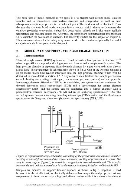
a load-lock. The arrangement is schematically shown <strong>in</strong> fig. 2. One of the systems conta<strong>in</strong>s a<br />
s<strong>in</strong>gle-crystal micro-flow reactor <strong>in</strong>tegrated <strong>in</strong>to the high-pressure chamber which will be<br />
described <strong>in</strong> more detail <strong>in</strong> section 3.2. All systems conta<strong>in</strong> facilities for sample preparation<br />
(sample heat<strong>in</strong>g and cool<strong>in</strong>g, sputter gun, evaporators, gas <strong>in</strong>let systems) and an optics for<br />
low-energy electron diffraction (LEED). As specialties, one system conta<strong>in</strong>s equipment for<br />
thermal desorption mass spectroscopy (TDS) and a spectrometer for Auger electron<br />
spectroscopy (AES) and the sample can be transferred <strong>in</strong>to a further chamber with a<br />
photoelectron emission microscope (PEEM) and an ion scatter<strong>in</strong>g spectrometer (ISS). The<br />
second system conta<strong>in</strong>s a scann<strong>in</strong>g tunnel<strong>in</strong>g microscopy (STM) system and the third one a<br />
spectrometer for X-ray and ultraviolet photoelectron spectroscopy (XPS, UPS).<br />
Figure 2: Experimental setup, schematic, consist<strong>in</strong>g of the preparation and analysis chamber<br />
work<strong>in</strong>g at ultrahigh vacuum and the reactor chamber, work<strong>in</strong>g at pressures up to 1 bar. The<br />
sample on its support (figure 3) is moved by a magnetically coupled transfer rod. The transfer<br />
between the rod ond the manipulator M or the reactor is accomplished by wobble sticks WS.<br />
Samples are mounted on sapphire transfer supports as shown <strong>in</strong> fig. 3. Sapphire is used<br />
because it is chemically <strong>in</strong>ert, mechanically stable and has unique thermal properties. At low<br />
temperature, its heat conductivity is high and allows cool<strong>in</strong>g while it is a thermal <strong>in</strong>sulator at<br />
Prepr<strong>in</strong>t of the Department of Inorganic Chemistry, Fritz-Haber-Institute of the MPG (for personal use only), www.fhi-berl<strong>in</strong>.mpg.de