Circuit Quantum Electrodynamics - Yale School of Engineering ...
Circuit Quantum Electrodynamics - Yale School of Engineering ...
Circuit Quantum Electrodynamics - Yale School of Engineering ...

Create successful ePaper yourself
Turn your PDF publications into a flip-book with our unique Google optimized e-Paper software.
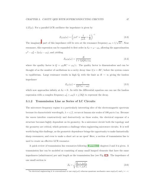
CHAPTER 3. CAVITY QED WITH SUPERCONDUCTING CIRCUITS 47<br />
1/Z(ω). For a parallel LCR oscillator the impedance is given by<br />
ZLCR(ω) =<br />
�<br />
jωC + 1<br />
�−1 1<br />
+<br />
jωL R<br />
The imaginary 1 part <strong>of</strong> this impedance will be zero at the resonance frequency ω0 = 1/ √ LC. Near<br />
resonance, this expression can be expanded to first order in δω = ω −ω0, allowing the approximation<br />
ω 2 − ω 2 0 ∼ 2ω(ω − ω0), and yielding<br />
R<br />
ZLCR(ω) =<br />
1 + 2jQδω/ω0<br />
where the quality factor is Q = ω0RC = ω0/γ. The quality factor is dimensionless and can be<br />
thought <strong>of</strong> as the number <strong>of</strong> oscillations in a cavity decay time 2/κ = RC, before the system comes<br />
to equilibrium. Large resistance results in high Q, with the limit as R → ∞ giving the lossless<br />
impedance<br />
ZLC(ω) =<br />
1<br />
2jC(ω − ω0)<br />
which now approaches infinity at δω = 0. As with the differential equation one can use the lossless<br />
expression with a complex frequency ω ′ 0 = ω0(1 + j/2Q) to represent the decay.<br />
3.1.2 Transmission Line as Series <strong>of</strong> LC <strong>Circuit</strong>s<br />
The microwave frequency regime is a particularly interesting slice <strong>of</strong> the electromagnetic spectrum<br />
because its characteristic wavelength, λ = c/f, occurs at human size scales <strong>of</strong> 100 µmto 1 m. Because<br />
the waves interfere constructively and destructively on these scales, the electrical response <strong>of</strong> a<br />
structure becomes highly dependent on its geometry. In a microwave circuit both the topology and<br />
the geometry are critical, which presents a challenge when engineering microwave circuits. It is well<br />
worth facing this challenge, as the geometric dependence brings the opportunity to make fantastically<br />
sharp resonances, and even to make a short act as an open! Here, a section <strong>of</strong> transmission line is<br />
used to create an effective LCR resonator.<br />
A quick review <strong>of</strong> transmission line resonators following [Pozar1990] chapters 2 and 3 is given. A<br />
transmission line can be modeled as consisting <strong>of</strong> many small lumped elements that have the same<br />
impedances (admittances) per unit length as the transmission line (see Fig. 3.2). The impedance <strong>of</strong><br />
one small section is<br />
Z0 =<br />
�<br />
Rℓ + jωLℓ<br />
Gℓ + jωCℓ<br />
1 In electrical engineering it is conventional to use exp(jωt) whereas quantum mechanics uses exp(iωt) and j = −i.<br />
(3.3)<br />
(3.4)<br />
(3.5)<br />
(3.6)