Typical requirements MBN10284-2:2011-04 - IEEE.org
Typical requirements MBN10284-2:2011-04 - IEEE.org
Typical requirements MBN10284-2:2011-04 - IEEE.org

Create successful ePaper yourself
Turn your PDF publications into a flip-book with our unique Google optimized e-Paper software.
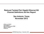
<strong>IEEE</strong> RTPGE information<br />
Answers to PoE and Channel Model ad hoc<br />
Stefan Buntz, Thilo Streichert, RD/ESA
additional/updated questions from RTPGE<br />
Should be answerd by the automotive OEMs, latest to the next <strong>IEEE</strong> meeting in<br />
San Diego (16th of July).<br />
Channel Ad-hoc questionaire<br />
Adobe Acrobat<br />
Document<br />
PoE Ad-hoc questionaire<br />
Adobe Acrobat<br />
Document<br />
http://www.ieee802.<strong>org</strong>/3/RTPGE/email/pdf0CEXtJtDjK.pdf http://www.ieee802.<strong>org</strong>/3/RTPGE/email/pdfVRBHUACjGc.pdf<br />
Stefan Buntz, Thilo Streichert, RD/ESA 2
PoE answers<br />
Question Answer<br />
1. Is PoE as defined in Clause 33 of the<br />
current standard adequate for RTPGE?<br />
2. Will vehicles use a mix of Clause 33 and<br />
non--clause 33 connections?<br />
3. Will PSE ports be dedicated to a specific<br />
load or do they need to be “universal”?<br />
From our point of view no<br />
4. What line voltage should be used? 12V/24V, maybe 5V, for future also 48V<br />
5. What power levels are required? Arbitrary (1W to maybe 25W), but static<br />
power <strong>requirements</strong><br />
6. Will multiple power classes be required? If this is an advantage, e.g. in cost<br />
(diameter<br />
7. Will the power system need to support<br />
surge loads (motor start)?<br />
no<br />
Very unlikely<br />
Stefan Buntz, Thilo Streichert, RD/ESA 3
PoE answers<br />
Question Answer<br />
8. What are the isolation <strong>requirements</strong>? Not sure about?<br />
9. What action should a PSE take if a power<br />
fault is detected?<br />
Switch to save state and report to<br />
diagnosis (e.g. register)<br />
10. Is a chassis ground always available? No, e.g. in mirrors<br />
11. Will we need to support<br />
adding/subtracting nodes to/from a live<br />
system (for example, a vehicle trailer or<br />
customer--installed equipment)?<br />
12. What is the maximum length of a PoE<br />
segment?<br />
13. Will PoE channels be treated differently<br />
(e.g., different wire gauge) than non-- PoE<br />
channels?<br />
Very unlikely<br />
Same like others (15m / 40m)<br />
If this is an advantage, e.g. in cost<br />
(diameter)<br />
Stefan Buntz, Thilo Streichert, RD/ESA 4
PoE answers<br />
Question Answer<br />
14. Do we need to support daisy--chain<br />
configurations?<br />
15. What is the estimated ratio of powered<br />
to unpowered ports?<br />
unlikely<br />
There will be more unpowered ports<br />
Stefan Buntz, Thilo Streichert, RD/ESA 5
Answers to Automotive cabling survey<br />
• Your Name: Helmut Leier, Thilo Streichert, Stefan Buntz<br />
Your Company Name: Daimler AG<br />
City/State/Zip: Germany, Ulm, Wilhelm-Runge-Strasse 11<br />
E-MAIL: stefan.buntz@daimler.com<br />
Your Job Function: Research/Development Engineer<br />
2. Wire harness or assembly topology (see Figure 1).<br />
2.1 Maximum length in meters of wire harness or assembly between active electronic devices – report current applications and lengths<br />
[EC] to [EC]. car/van:12m, truck/bus: 32m<br />
2.2 Maximum length in meters of wire harness or assembly between active electronic devices – report future applications and lengths<br />
[EC] to [EC]. car/van:15m, truck/bus: 40m<br />
2.3 Number and type of inline connectors [C] between active electronic devices – report current applications.<br />
number of connectors 3 type of connector(s) typical connectors are Tyco (TE) MQS, nanoMQS, MLK, … different multi-pin connectors<br />
within one link are possible<br />
2.4 Number and type of inline connectors [C] between active electronic devices– report future applications.<br />
number of connectors 3 type of connector(s) typical connectors are Tyco (TE) MQS, nanoMQS, MLK, … different multi-pin connectors<br />
within one link are possible<br />
2.5 Type of active electronic connectors [AEC] – report current applications.<br />
type of connector(s) typical connectors are Tyco (TE) MQS, nanoMQS, MLK, …<br />
2.6 Type of active electronic connectors [AEC] – report future applications.<br />
type of connector(s) typical connectors are Tyco (TE) MQS, nanoMQS, MLK, …<br />
Stefan Buntz, Thilo Streichert, RD/ESA 6
Answers to Automotive cabling survey<br />
2.7 Are there <strong>requirements</strong> for future applications to be mechanically compatible to existing connector systems?<br />
not necessarily<br />
2.8 Are there <strong>requirements</strong> for mechanically compatible connector systems between automobile manufacturers?<br />
Not necessarily, however due to same <strong>requirements</strong> and cost aspects same connector is likely<br />
3. Balanced twisted-pair cable used in wire harness or assembly (see Figure 1 and Figure 2.) report parameters and values.<br />
3.1 Current automotive applications<br />
• Gauge [AWG] [or conductor in mm]<br />
• Impedance [ohm +/- ]<br />
• Shield [Y/N] [shield type]<br />
• Copper conductors [Y/N] solid [Y/N] stranded [#strands]<br />
• Direct current resistance [milliohm/meter]<br />
3.2 Future automotive applications<br />
• Gauge [AWG] [or conductor in mm]<br />
• Impedance [ohm +/- ]<br />
• Shield [Y/N] [shield type]<br />
• Copper conductors [Y/N] solid [Y/N] stranded [#strands]<br />
• Direct current resistance [milliohm/meter]<br />
� See next slide<br />
Stefan Buntz, Thilo Streichert, RD/ESA 7
Answers to Automotive cabling survey<br />
4. Bundled cable types in wire harnesses or assemblies (Figure 1)<br />
4.1 Report data rates and signaling schemes for differential signaling applications in bundle [data rates and signaling].<br />
� See next slide<br />
4.2 Report other data rates and signaling schemes not using differential signaling in bundle [data rates and signaling].<br />
� See next slide<br />
4.3 Report voltage/power in bundle [ ]<br />
12V (cars), 24V (trucks, busses) and 48V (future supply voltage)<br />
currents are up to 150A@12V (e.g. steering, air condition, …).<br />
5. External noise sources � see following slides<br />
5.1 Report steady state noise (including frequency content)<br />
5.2 Report time variable noise (things that come and go)<br />
5.3 Report impulse noise<br />
5.4 Report radio frequency interference - modulated signals (i.e., cell phone type signals)<br />
Stefan Buntz, Thilo Streichert, RD/ESA 8
<strong>Typical</strong> automotive bus systems and cabeling<br />
• Overview over typical automotive bus systems, their voltage levels and cables and connectors<br />
system LIN CAN(500<br />
kbit/s*)<br />
FlexRay USB<br />
(HiSpeed)<br />
HSVL<br />
(„LVDS“)<br />
RF-signals<br />
Data rate 20 kbit/s 500 kbit/s 10 Mbit/s 480 Mbit/s 200…3000 Mbit/s Antenna signals<br />
(AM, FM, ISM, WLAN, Bluetooth,<br />
…)<br />
amplitude 12 V 2V 0,6V 0,4V 0,25…0,45V different<br />
differential? single-ended differential differential differential differential single-ended<br />
typical cabling Single wire,<br />
e.g. 0,35mm²<br />
Differential Cable<br />
impedance (Z diff Ω)<br />
UTP 2x0,35mm² UTP<br />
(e.g. FLR9Y 2x0,35 mm²-SN)<br />
STQ 4x0,5mm² (e.g.<br />
Leoni Dacar566)<br />
STQ 4x0,14mm²<br />
(e.g. Leoni Dacar535-2)<br />
Coax<br />
(e.g. Leoni Dacar302)<br />
- 120 (±12) 100 (±10) 90 (±15) 100 (±15) 50 (±3)<br />
Shield? no no no yes (braid + foil) yes (braid + foil) yes (braid + foil)<br />
conductor stranded<br />
(e.g. 7)<br />
Stranded<br />
(e.g. 7)<br />
stranded<br />
(e.g. 7x0,26)<br />
stranded<br />
(e.g. 19x0,182)<br />
stranded<br />
(e.g. 7x0,16)<br />
stranded<br />
(e.g. 7x0,27)<br />
Jacketed? - no no yes yes yes<br />
typical connector different multi pin<br />
connectors<br />
(e.g. Tyco MQS)<br />
different multi pin<br />
connectors<br />
(e.g. Tyco MQS)<br />
*) different data rates are possible for CAN, typically are 125kbit/s or 500kbit/s<br />
different multi pin<br />
connectors<br />
(e.g. Tyco MQS)<br />
Rosenberger HSD Rosenberger HSD FAKRA<br />
Stefan Buntz, Thilo Streichert, RD/ESA 9
<strong>Typical</strong> <strong>requirements</strong> <strong>MBN10284</strong>-2:<strong>2011</strong>-<strong>04</strong><br />
• Overall <strong>requirements</strong> (Step size, measurement time, BW)<br />
BW<br />
(kHz)<br />
Max. frequency<br />
step size<br />
PK QP AV<br />
Min. measurement<br />
time (ms)<br />
Max. frequency<br />
step size<br />
Min. measurement<br />
time (ms)<br />
• RF Emissions – antenna test<br />
according to CISPR25, section 6.4<br />
�limit diagrams for different BW/detectors (see next slide)<br />
Max. frequency<br />
step size<br />
Min. measurement<br />
time (ms)<br />
9 ≤0,5 x BW 50 ≤5 x BW 1000 ≤0,5 x BW 50<br />
120 ≤0,5 x BW 5 ≤5 x BW 1000 ≤0,5 x BW 5<br />
1000 ≤0,5 x BW 50 - - ≤0,5 x BW 50<br />
Stefan Buntz, Thilo Streichert, RD/ESA 10
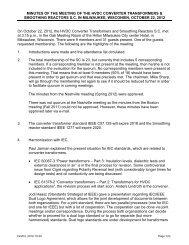
<strong>Typical</strong> <strong>requirements</strong> <strong>MBN10284</strong>-2:<strong>2011</strong>-<strong>04</strong><br />
limit diagrams for different BW/detectors<br />
antenna test, according to CISPR25, section<br />
6.4 (~1,7m cable, 1m in front of antenna)<br />
always lowest limit is valid.<br />
el. Feldstärke [dBµV/m]<br />
80<br />
60<br />
40<br />
20<br />
0<br />
-20<br />
Limits for 120kHz BW<br />
(PK) limits <strong>MBN10284</strong>: 120 kHz MaxPeak; 5 ms/pt<br />
(QP) limits <strong>MBN10284</strong>: 120 kHz QuasiPeak; 1 s/pt<br />
(AV) limits <strong>MBN10284</strong>: 120 kHz Average; 5 ms/pt<br />
100k 1M 10M<br />
Frequenz [Hz]<br />
100M 1G 3G<br />
100k 1M 10M<br />
Frequenz [Hz]<br />
100M 1G 3G<br />
Stefan Buntz, Thilo Streichert, RD/ESA 11<br />
el. Feldstärke [dBµV/m]<br />
80<br />
60<br />
40<br />
20<br />
0<br />
-20<br />
Limits for 9kHz BW<br />
Limits for 1000kHz BW<br />
(PK) limits <strong>MBN10284</strong>: 1 MHz MaxPeak; 50 ms/pt<br />
(QP) no limits for Quasi-Peak-Detector at 1 MHz RBW<br />
(AV) limits <strong>MBN10284</strong>: 1 MHz Average; 50 ms/pt
<strong>Typical</strong> <strong>requirements</strong> <strong>MBN10284</strong>-2:<strong>2011</strong>-<strong>04</strong><br />
• Bulk Current injection (BCI)<br />
acc. to ISO/DIS11452-4:2010-1<br />
test currents � see table on the<br />
right.<br />
In the formulas, f is the frequency<br />
in MHZ and lg denotes the<br />
logarithm to the base 10<br />
Frequency<br />
Range<br />
(MHz)<br />
Test Current<br />
(dBµA)<br />
0,1 … 2,38 90<br />
2,38 … 15 106 – 20 lg (15/f)<br />
15 … 30 106<br />
30 … 54 106<br />
54 … 65 100 – 10 lg (f/88)<br />
65 … 88 106<br />
88 … 140 100 – 10 lg (f/88)<br />
140 … 174 106 – 10 lg (f/88)<br />
174 … 380 97<br />
380 … 400 106 – 10 lg (f/88)<br />
Modulation<br />
CW<br />
and<br />
AM (1 kHz, 80%)<br />
Stefan Buntz, Thilo Streichert, RD/ESA 12
<strong>Typical</strong> <strong>requirements</strong> <strong>MBN10284</strong>-2:<strong>2011</strong>-<strong>04</strong><br />
• RF radiated immunity (ALSE test)<br />
acc. to ISO/DIS 11452-2:20<strong>04</strong>-11<br />
Frequency<br />
Range (MHz)<br />
Test level<br />
(V/m)<br />
Polarisation Modulations<br />
200 … 380 70 vert + hor CW and AM (1kHz, 80%)<br />
380 … 460 140 vert + hor CW and AM (1kHz, 80%)<br />
460 … 806 70 vert + hor CW and AM (1kHz, 80%)<br />
806 … 915 140 vert + hor CW and pulse modulation (577µs duration, 217Hz repetition rate)<br />
915 … 1200 70 vert + hor CW<br />
1200 … 1400 140 vert + hor CW and pulse modulation (3µs duration, 300Hz repetition rate)<br />
1400 … 1710 70 vert + hor CW<br />
1710 … 1910 140 vert + hor CW and pulse modulation (577µs duration, 217Hz repetition rate)<br />
1910 … 2700 70 vert + hor CW<br />
2700 … 3000 140 vert + hor CW and pulse modulation (3µs duration, 300Hz repetition rate)<br />
Stefan Buntz, Thilo Streichert, RD/ESA 13
<strong>Typical</strong> <strong>requirements</strong> <strong>MBN10284</strong>-2:<strong>2011</strong>-<strong>04</strong><br />
• Magnetic field immunity acc. to<br />
ISO 11452-8:2007-07<br />
Frequency<br />
Range (MHz)<br />
Test level<br />
(A/m)<br />
Modulation<br />
0 (DC) 1000 DC<br />
0,015 … 0,06 1000 CW<br />
0,06 … 6 60/f CW<br />
6 … 30 10 CW<br />
• transient pulses on data lines acc. to ISO7637-3:<br />
• Slow transient with inductive coupling (ICC), requirement: ±6V,<br />
• Fast Transient with capacitive coupling (CCC), requirement: -75V/+60V<br />
Stefan Buntz, Thilo Streichert, RD/ESA 14
<strong>Typical</strong> <strong>requirements</strong> <strong>MBN10284</strong>-2:<strong>2011</strong>-<strong>04</strong><br />
• ESD <strong>requirements</strong><br />
• ESD Handling Test acc. to ISO10605:2008-07, section 9 (150pF, 330Ω)<br />
Discharge type pins Housing<br />
Air discharge - 10 discharges<br />
±4kV, ±8kV and ±15kV<br />
Contact discharge 3 discharges<br />
±2kV, ±4kV and ±6kV<br />
Discharge points Plastics Discharge points Plastics<br />
10 discharges<br />
±15kV<br />
- 5 discharges<br />
±4kV and ±8kV<br />
• ESD Direct Discharge acc. to ISO 10605:2008-07, Annex F (330pF, 330Ω)<br />
Discharge type pins Housing, periphery, switches, displays, …<br />
Air discharge - 10 discharges<br />
±4kV, ±8kV and ±15kV<br />
Contact discharge 3 discharges<br />
±2kV, ±4kV and ±6kV<br />
Discharge points Plastics Discharge points Plastics<br />
10 discharges<br />
±15kV<br />
- 10 discharges<br />
±4kV and ±8kV<br />
• ESD Indirect Discharge acc. to ISO 10605:2008-07, Annex F (330pF, 330Ω)<br />
Discharge type Discharge islands<br />
Air discharge -<br />
Contact discharge 10 discharges<br />
±4kV, ±8kV and ±15kV<br />
Stefan Buntz, Thilo Streichert, RD/ESA 15
Open questions/issues<br />
• The above shown EMC <strong>requirements</strong> describe the overall performance. For<br />
the individual System Components (PHY/Filtering/PCB/Connectors/Cables)<br />
dedicated <strong>requirements</strong> must be derived.<br />
• Therefore we see the need that chip designers derive the respective<br />
<strong>requirements</strong> for the other system components out of their solution.<br />
� e.g. How much unsymmetry (TLC, TLTC) does the (planned) chip/system<br />
allow in order to still fullfill the shown <strong>requirements</strong>?<br />
Stefan Buntz, Thilo Streichert, RD/ESA 16
exemplary automotive cable harness<br />
�overview / parts of the cable harness<br />
• engine harness<br />
• cockpit-harness<br />
• Powertrain harness<br />
� examples of connectors<br />
� TDR measurements (impedance)<br />
� S-parameter measurements<br />
Stefan Buntz, Thilo Streichert, RD/ESA<br />
17
Mercedes-Benz S-Class (2006) complete cable harness<br />
• about 38kg, following slides show details<br />
of this harness (parts of some dedicated<br />
harnesses)<br />
Stefan Buntz, Thilo Streichert, RD/ESA 18
engine harness (e.g. headlights)<br />
Stefan Buntz, Thilo Streichert, RD/ESA<br />
19
cockpit harness<br />
Stefan Buntz, Thilo Streichert, RD/ESA<br />
20
ody harness (part)<br />
Stefan Buntz, Thilo Streichert, RD/ESA<br />
21
connector examples (CAN star coupler)<br />
• CAN cables:<br />
70mm of untwisted cable<br />
Stefan Buntz, Thilo Streichert, RD/ESA<br />
7 cm<br />
22
connector examples<br />
Stefan Buntz, Thilo Streichert, RD/ESA 23
TDR measurements<br />
• CAN connection of headlights (engine compartment, no inline connectors)<br />
• cable harness 50mm above GND, no inline connectors<br />
Stefan Buntz, Thilo Streichert, RD/ESA<br />
24
TDR measurements<br />
Stefan Buntz, Thilo Streichert, RD/ESA<br />
ca. 1.80m ca. 4.00m<br />
25
S-Parameter Port3<br />
Port4<br />
Stefan Buntz, Thilo Streichert, RD/ESA<br />
Port1<br />
Port2<br />
ca. 1.80m<br />
26
S-Parameter<br />
Stefan Buntz, Thilo Streichert, RD/ESA<br />
Port1<br />
Port2<br />
Port3<br />
Port4<br />
ca. 4.00m<br />
27
S-parameter with (simple) in-line-connector<br />
Port 1<br />
ca. 5.60m ca. 2.10m<br />
In-Line-Stecker Port 2<br />
Stefan Buntz, Thilo Streichert, RD/ESA 28
S-Parameter with In-line-connector<br />
Stefan Buntz, Thilo Streichert, RD/ESA<br />
29
summary<br />
• The shown pictures are just examples of an automotive cable harness<br />
• The shown s-Parameter measurements are also just examples (and by way not<br />
the „worst case“) of how an automotive channel coul look like.<br />
Stefan Buntz, Thilo Streichert, RD/ESA 30
Automotive <strong>requirements</strong> for Connector<br />
• a multi-pin connector must be possible (e.g. similar to MQS)<br />
• A possibility for contacting shielded cables must be possible inside the multipin<br />
connector<br />
Stefan Buntz, Thilo Streichert, RD/ESA 31