Specification of the Bluetooth System - IEEE.org
Specification of the Bluetooth System - IEEE.org
Specification of the Bluetooth System - IEEE.org

You also want an ePaper? Increase the reach of your titles
YUMPU automatically turns print PDFs into web optimized ePapers that Google loves.
<strong>Specification</strong> Volume 1<br />
<strong>Specification</strong><br />
<strong>of</strong> <strong>the</strong> <strong>Bluetooth</strong> <strong>System</strong><br />
Wireless connections made easy<br />
Core<br />
v1.0 B<br />
December 1st 1999
BLUETOOTH DOC<br />
Date / Day-Month-Year<br />
01 Dec 99<br />
Responsible e-mail address<br />
N.B.<br />
<strong>Specification</strong><br />
<strong>of</strong> <strong>the</strong> <strong>Bluetooth</strong> <strong>System</strong><br />
Version 1.0 B<br />
Document No.<br />
Status<br />
page 3 <strong>of</strong> 1082<br />
1.C.47/1.0 B<br />
3
BLUETOOTH SPECIFICATION Version 1.0 B page 4 <strong>of</strong> 1082<br />
Revision History<br />
The Revision History is shown in Appendix I on page 868<br />
Contributors<br />
The persons who contributed to this specification are listed in<br />
Appendix II on page 879.<br />
Web Site<br />
This specification can also be found on <strong>the</strong> <strong>Bluetooth</strong> website:<br />
http://www.bluetooth.com<br />
Disclaimer and copyright notice<br />
THIS SPECIFICATION IS PROVIDED “AS IS” WITH NO WARRANTIES<br />
WHATSOEVER, INCLUDING ANY WARRANTY OF MERCHANTABILITY,<br />
NONINFRINGEMENT, FITNESS FOR ANY PARTICULAR PURPOSE, OR<br />
ANY WARRANTY OTHERWISE ARISING OUT OF ANY PROPOSAL, SPECI-<br />
FICATION OR SAMPLE. All liability, including liability for infringement <strong>of</strong> any<br />
proprietary rights, relating to use <strong>of</strong> information in this document is disclaimed.<br />
No license, express or implied, by estoppel or o<strong>the</strong>rwise, to any intellectual<br />
property rights are granted herein.<br />
Copyright © 1999<br />
Telefonaktiebolaget LM Ericsson,<br />
International Business Machines Corporation,<br />
Intel Corporation,<br />
Nokia Corporation,<br />
Toshiba Corporation .<br />
*Third-party brands and names are <strong>the</strong> property <strong>of</strong> <strong>the</strong>ir respective owners.<br />
4
BLUETOOTH SPECIFICATION Version 1.0 B page 5 <strong>of</strong> 1082<br />
MASTER TABLE OF CONTENTS<br />
For <strong>the</strong> <strong>Bluetooth</strong> Pr<strong>of</strong>iles, See Volume 2.<br />
Part A Volume 1 (1:2)<br />
RADIO SPECIFICATION<br />
Contents .......................................................................................[A] 17<br />
1 Scope............................................................................. [A] 18<br />
2 Frequency Bands and Channel Arrangement................ [A] 19<br />
3 Transmitter Characteristics ............................................ [A] 20<br />
4 Receiver Characteristics ................................................ [A] 24<br />
5 Appendix A..................................................................... [A] 28<br />
6 Appendix B..................................................................... [A] 31<br />
Part B Volume 1 (1:2)<br />
BASEBAND SPECIFICATION<br />
Contents .......................................................................................[B] 35<br />
1 General Description ....................................................... [B] 41<br />
2 Physical Channel ........................................................... [B] 43<br />
3 Physical Links ................................................................ [B] 45<br />
4 Packets .......................................................................... [B] 47<br />
5 Error Correction.............................................................. [B] 67<br />
6 Logical Channels............................................................ [B] 77<br />
7 Data Whitening............................................................... [B] 79<br />
8 Transmit/Receive Routines ............................................ [B] 81<br />
9 Transmit/Receive Timing................................................ [B] 87<br />
10 Channel Control ............................................................. [B] 95<br />
11 Hop Selection............................................................... [B] 127<br />
12 <strong>Bluetooth</strong> Audio............................................................ [B] 139<br />
13 <strong>Bluetooth</strong> Addressing................................................... [B] 143<br />
14 <strong>Bluetooth</strong> Security........................................................ [B] 149<br />
15 List <strong>of</strong> Figures............................................................... [B] 179<br />
16 List <strong>of</strong> Tables ................................................................ [B] 183<br />
28 November 1999 5
BLUETOOTH SPECIFICATION Version 1.0 B page 6 <strong>of</strong> 1082<br />
Part C Volume 1 (1:2)<br />
LINK MANAGER PROTOCOL<br />
Contents ....................................................................................[C] 187<br />
1 General ........................................................................ [C] 191<br />
2 Format <strong>of</strong> LMP ............................................................. [C] 192<br />
3 The Procedure Rules and PDUs................................... [c] 193<br />
4 Connection Establishment ........................................... [C] 225<br />
5 Summary <strong>of</strong> PDUs.......................................................[C] 226<br />
6 Test Modes .................................................................. [C] 237<br />
7 Error Handling.............................................................. [C] 239<br />
8 List <strong>of</strong> Figures .............................................................. [C] 241<br />
9 List <strong>of</strong> Tables................................................................ [C] 243<br />
Part D Volume 1 (1:2)<br />
LOGICAL LINK CONTROL AND ADAPTATION PROTOCOL<br />
SPECIFICATION<br />
Contents ....................................................................................[D] 247<br />
1 Introduction .................................................................. [D] 249<br />
2 General Operation ....................................................... [D] 253<br />
3 State Machine.............................................................. [D] 258<br />
4 Data Packet Format..................................................... [D] 272<br />
5 Signalling ..................................................................... [D] 275<br />
6 Configuration Parameter Options ................................ [D] 289<br />
7 Service Primitives ........................................................ [D] 295<br />
8 Summary...................................................................... [D] 313<br />
9 References .................................................................. [D] 314<br />
10 List <strong>of</strong> Figures .............................................................. [D] 315<br />
11 List <strong>of</strong> Tables................................................................ [D] 316<br />
Terms and Abbreviations .................................................. [D] 317<br />
Appendix A: Configuration MSCs .....................................[D] 318<br />
Appendix B: Implementation Guidelines ........................... [D] 321<br />
6 28 November 1999
BLUETOOTH SPECIFICATION Version 1.0 B page 7 <strong>of</strong> 1082<br />
Part E Volume 1 (1:2)<br />
SERVICE DISCOVERY PROTOCOL (SDP)<br />
Contents .....................................................................................[E] 325<br />
1 Introduction .................................................................. [E] 327<br />
2 Overview ...................................................................... [E] 330<br />
3 Data Representation .................................................... [E] 341<br />
4 Protocol Description..................................................... [E] 344<br />
5 Service Attribute Definitions......................................... [E] 358<br />
Appendix A– Background Information ............................... [E] 370<br />
Appendix B – Example SDP Transactions ........................ [E] 371<br />
Part F:1 Volume 1 (1:2)<br />
RFCOMM WITH TS 07.10<br />
Contents ..................................................................................[F:1] 387<br />
1 Introduction ............................................................... [F:1] 389<br />
2 RFCOMM Service Overview ..................................... [F:1] 391<br />
3 Service Interface Description .................................... [F:1] 395<br />
4 TS 07.10 Subset Supported by RFCOMM................ [F:1] 396<br />
5 TS 07.10 Adaptations for RFCOMM ......................... [F:1] 398<br />
6 Flow Control .............................................................. [F:1] 403<br />
7 Interaction with O<strong>the</strong>r Entities ................................... [F:1] 405<br />
8 References................................................................ [F:1] 408<br />
9 Terms and Abbreviations........................................... [F:1] 409<br />
Part F:2 Volume 1 (1:2)<br />
IrDA INTEROPERABILITY<br />
Contents ..................................................................................[F:2] 413<br />
1 Introduction ............................................................... [F:2] 414<br />
2 OBEX Object and Protocol........................................ [F:2] 417<br />
3 OBEX over RFCOMM ............................................... [F:2] 421<br />
4 OBEX over TCP/IP.................................................... [F:2] 423<br />
5 <strong>Bluetooth</strong> Application Pr<strong>of</strong>iles using OBEX............... [F:2] 425<br />
6 References................................................................ [F:2] 427<br />
7 List <strong>of</strong> Acronyms and Abbreviations.......................... [F:2] 428<br />
28 November 1999 7
BLUETOOTH SPECIFICATION Version 1.0 B page 8 <strong>of</strong> 1082<br />
Part F:3 Volume 1 (1:2)<br />
TELEPHONY CONTROL PROTOCOL SPECIFICATION<br />
Contents ................................................................................. [F:3] 431<br />
1 General Description ...................................................[F:3] 435<br />
2 Call Control (CC)........................................................[F:3] 439<br />
3 Group Management (GM)..........................................[F:3] 449<br />
4 Connectionless TCS (CL) ..........................................[F:3] 455<br />
5 Supplementary Services (SS)....................................[F:3] 456<br />
6 Message formats .......................................................[F:3] 459<br />
7 Message coding.........................................................[F:3] 471<br />
8 Message Error handling.............................................[F:3] 487<br />
9 Protocol Parameters ..................................................[F:3] 489<br />
10 References ................................................................[F:3] 490<br />
11 List <strong>of</strong> Figures ............................................................[F:3] 491<br />
12 List <strong>of</strong> Tables..............................................................[F:3] 492<br />
Appendix 1 - TCS Call States .........................................[F:3] 493<br />
Part F:4 Volume 1 (1:2)<br />
INTEROPERABILITY REQUIREMENTS FOR BLUETOOTH AS A WAP BEARER<br />
Contents ................................................................................. [F:4] 497<br />
1 Introduction ................................................................[F:4] 499<br />
2 The Use <strong>of</strong> WAP In <strong>the</strong> <strong>Bluetooth</strong> Environment.........[F:4] 500<br />
3 WAP Services Overview ............................................[F:4] 502<br />
4 WAP in <strong>the</strong> <strong>Bluetooth</strong> Piconet....................................[F:4] 506<br />
5 Interoperability Requirements....................................[F:4] 511<br />
6 Service Discovery ......................................................[F:4] 512<br />
7 References ................................................................[F:4] 515<br />
8 28 November 1999
BLUETOOTH SPECIFICATION Version 1.0 B page 9 <strong>of</strong> 1082<br />
Part H:1 Volume 1 (2:2)<br />
HOST CONTROLLER INTERFACE FUNCTIONAL SPECIFICATION<br />
Contents ................................................................................. [H:1] 519<br />
1 Introduction ............................................................... [H:1] 524<br />
2 Overview <strong>of</strong> Host Controller Transport Layer............ [H:1] 528<br />
3 HCI Flow Control....................................................... [H:1] 529<br />
4 HCI Commands......................................................... [H:1] 531<br />
5 Events ....................................................................... [H:1] 703<br />
6 List <strong>of</strong> Error Codes .................................................... [H:1] 745<br />
7 List <strong>of</strong> Acronyms and Abbreviations.......................... [H:1] 755<br />
8 List <strong>of</strong> Figures............................................................ [H:1] 756<br />
9 List <strong>of</strong> Tables ............................................................. [H:1] 757<br />
Part H:2 Volume 1 (2:2)<br />
HCI USB TRANSPORT LAYER<br />
Contents ................................................................................. [H:2] 761<br />
1 Overview ................................................................... [H:2] 762<br />
2 USB Endpoint Expectations...................................... [H:2] 764<br />
3 Class Code................................................................ [H:2] 771<br />
4 Device Firmware Upgrade ........................................ [H:2] 772<br />
5 Limitations................................................................. [H:2] 773<br />
Part H:3 Volume 1 (2:2)<br />
HCI RS232 TRANSPORT LAYER<br />
Contents ................................................................................. [H:3] 777<br />
1 General ..................................................................... [H:3] 778<br />
2 Overview ................................................................... [H:3] 779<br />
3 Negotiation Protocol.................................................. [H:3] 780<br />
4 Packet Transfer Protocol........................................... [H:3] 784<br />
5 Using delimiters with COBS for synchronization....... [H:3] 785<br />
6 Using RTS/CTS for Synchronization......................... [H:3] 788<br />
7 References................................................................ [H:3] 794<br />
28 November 1999 9
BLUETOOTH SPECIFICATION Version 1.0 B page 10 <strong>of</strong> 1082<br />
Part H:4 Volume 1 (2:2)<br />
HCI UART TRANSPORT LAYER<br />
Contents .................................................................................[H:4] 797<br />
1 General ..................................................................... [H:4] 798<br />
2 Protocol..................................................................... [H:4] 799<br />
3 RS232 Settings......................................................... [H:4] 800<br />
4 Error Recovery.......................................................... [H:4] 801<br />
Part I:1 Volume 1 (2:2)<br />
BLUETOOTH TEST MODE<br />
Contents .................................................................................. [I:1] 805<br />
1 General Description ....................................................[I:1] 806<br />
2 Test Scenarios ............................................................[I:1] 808<br />
3 Outline <strong>of</strong> Proposed LMP Messages ..........................[I:1] 817<br />
4 References .................................................................[I:1] 819<br />
Part I:2 Volume 1 (2:2)<br />
BLUETOOTH COMPLIANCE REQUIREMENTS<br />
Contents ................................................................................. [I:2] 823<br />
1 Scope..........................................................................[I:2] 825<br />
2 Terms Used.................................................................[I:2] 826<br />
3 Legal Aspects .............................................................[I:2] 828<br />
4 The Value <strong>of</strong> <strong>the</strong> <strong>Bluetooth</strong> Brand ...............................[I:2] 829<br />
5 The <strong>Bluetooth</strong> Qualification Program ..........................[I:2] 830<br />
6 <strong>Bluetooth</strong> License Requirements for Products............[I:2] 832<br />
7 <strong>Bluetooth</strong> License Provisions for Early Products ........[I:2] 836<br />
8 <strong>Bluetooth</strong> Brand License Provisions for Special<br />
Products & Marketing..................................................[I:2] 837<br />
9 Recommendations Concerning Information about<br />
a Product’s <strong>Bluetooth</strong> Capabilities ..............................[I:2] 838<br />
10 Quality Management, Configuration Management<br />
and Version Control ....................................................[I:2] 839<br />
11 Appendix A – Example <strong>of</strong> a<br />
“<strong>Bluetooth</strong> Capability Statement” ................................[I:2] 840<br />
12 Appendix B - Marketing Names <strong>of</strong> <strong>Bluetooth</strong> Pr<strong>of</strong>iles .[I:2] 841<br />
10 28 November 1999
BLUETOOTH SPECIFICATION Version 1.0 B page 11 <strong>of</strong> 1082<br />
Part I:3 Volume 1 (2:2)<br />
TEST CONTROL INTERFACE<br />
Contents ................................................................................... [I:3] 845<br />
1 Introduction .................................................................[I:3] 847<br />
2 General Description ....................................................[I:3] 849<br />
3 Test Configurations .....................................................[I:3] 854<br />
4 TCI-L2CAP <strong>Specification</strong> ............................................[I:3] 856<br />
5 Abbreviations ..............................................................[I:3] 866<br />
Part K Pr<strong>of</strong>iles - see Volume 2<br />
Appendix I Volume 1 (2:2)<br />
REVISION HISTORY . . . . . . . . . . . . . . . . . . . . . . . . . . . . . . . . . . . . . .[@:I] 868<br />
Appendix II Volume 1 (2:2)<br />
CONTRIBUTORS . . . . . . . . . . . . . . . . . . . . . . . . . . . . . . . . . . . . . . . [@:II] 881<br />
Appendix III Volume 1 (2:2)<br />
ACRONYMS AND ABBREVIATIONS. . . . . . . . . . . . . . . . . . . . . . . .[@:III] 891<br />
Appendix IV Volume 1 (2:2)<br />
SAMPLE DATA<br />
Contents ............................................................................... [@:IV] 901<br />
1 Encryption Sample Data .........................................[@:IV] 902<br />
2 Frequency Hopping Sample Data—Mandatory<br />
Scheme...................................................................[@:IV] 937<br />
3 Access Code Sample Data .....................................[@:IV] 950<br />
4 HEC and Packet Header Sample Data...................[@:IV] 953<br />
5 CRC Sample Data...................................................[@:IV] 954<br />
6 Complete Sample Packets......................................[@:IV] 955<br />
7 Whitening Sequence Sample Data .........................[@:IV] 957<br />
8 FEC Sample Data ...................................................[@:IV] 960<br />
9 Encryption Key Sample Data ..................................[@:IV] 961<br />
28 November 1999 11
BLUETOOTH SPECIFICATION Version 1.0 B page 12 <strong>of</strong> 1082<br />
Appendix V Volume 1 (2:2)<br />
BLUETOOTH AUDIO<br />
Contents ............................................................................... [@:V] 987<br />
1 General Audio Recommendations...........................[@:V] 989<br />
Appendix VI Volume 1 (2:2)<br />
BASEBAND TIMERS<br />
Contents .............................................................................. [@:VI] 995<br />
1 Baseband Timers....................................................[@:VI] 996<br />
Appendix VII Volume 1 (2:2)<br />
OPTIONAL PAGING SCHEMES<br />
Contents ........................................................................... [@:VII] 1001<br />
1 General ................................................................[@:VII] 1003<br />
2 Optional Paging Scheme I ...................................[@:VII] 1004<br />
Appendix VIII Volume 1 (2:2)<br />
BLUETOOTH ASSIGNED NUMBERS<br />
Contents .......................................................................... [@:VIII] 1011<br />
1 <strong>Bluetooth</strong> Baseband ...........................................[@:VIII] 1012<br />
2 Link Manager Protocol (LMP) .............................[@:VIII] 1018<br />
3 Logical Link Control and Adaptation Protocol.....[@:VIII] 1019<br />
4 Service Discovery Protocol (SDP) ......................[@:VIII] 1020<br />
5 References .........................................................[@:VIII] 1028<br />
6 Terms and Abbreviations ....................................[@:VIII] 1029<br />
7 List <strong>of</strong> Figures .....................................................[@:VIII] 1030<br />
8 List <strong>of</strong> Tables.......................................................[@:VIII] 1031<br />
12 28 November 1999
BLUETOOTH SPECIFICATION Version 1.0 B page 13 <strong>of</strong> 1082<br />
Appendix IX Volume 1 (2:2)<br />
MESSAGE SEQUENCE CHARTS<br />
Contents ............................................................................. [@:IX] 1035<br />
1 Introduction ...........................................................[@:IX] 1037<br />
2 Services Without Connection Request..................[@:IX] 1038<br />
3 ACL Connection Establishment and Detachment.[@:IX] 1042<br />
4 Optional Activities After ACL Connection<br />
Establishment........................................................[@:IX] 1050<br />
5 SCO Connection Establishment and Detachment [@:IX] 1059<br />
6 Special Modes: Sniff, Hold, Park...........................[@:IX] 1062<br />
7 Buffer Management, Flow Control ........................[@:IX] 1068<br />
8 Loopback Mode.....................................................[@:IX] 1070<br />
9 List <strong>of</strong> Acronyms and Abbreviations......................[@:IX] 1073<br />
10 List <strong>of</strong> Figures........................................................[@:IX] 1074<br />
11 List <strong>of</strong> Tables .........................................................[@:IX] 1075<br />
12 References............................................................[@:IX] 1076<br />
Alphabetical Index 1077<br />
28 November 1999 13
BLUETOOTH SPECIFICATION Version 1.0 B page 14 <strong>of</strong> 1082<br />
14 28 November 1999
Part A<br />
RADIO SPECIFICATION
BLUETOOTH SPECIFICATION Version 1.0 B page 17 <strong>of</strong> 1082<br />
Radio <strong>Specification</strong><br />
CONTENTS<br />
1 Scope ..................................................................................................18<br />
2 Frequency Bands and Channel Arrangement .................................19<br />
3 Transmitter Characteristics...............................................................20<br />
3.1 Modulation Characteristics.........................................................21<br />
3.2 Spurious Emissions....................................................................21<br />
3.2.1 In-band Spurious Emission ...........................................22<br />
3.2.2 Out-<strong>of</strong>-Band Spurious Emission....................................22<br />
3.3 Radio Frequency Tolerance .......................................................23<br />
4 Receiver Characteristics ...................................................................24<br />
4.1 Actual Sensitivity Level ..............................................................24<br />
4.2 Interference Performance ..........................................................24<br />
4.3 Out-<strong>of</strong>-band Blocking .................................................................25<br />
4.4 Intermodulation Characteristics..................................................25<br />
4.5 Maximum Usable Level..............................................................26<br />
4.6 Spurious Emissions....................................................................26<br />
4.7 Receiver Signal Strength Indicator (optional).............................26<br />
4.8 Reference Interference-signal Definition....................................27<br />
5 Appendix A .........................................................................................28<br />
6 Appendix B .........................................................................................31<br />
29 November 1999 17
BLUETOOTH SPECIFICATION Version 1.0 B page 18 <strong>of</strong> 1082<br />
Radio <strong>Specification</strong><br />
1 SCOPE<br />
The <strong>Bluetooth</strong> transceiver is operating in <strong>the</strong> 2.4 GHz ISM band. This specification<br />
defines <strong>the</strong> requirements for a <strong>Bluetooth</strong> transceiver operating in this unlicensed<br />
band.<br />
Requirements are defined for two reasons:<br />
• Provide compatibility between <strong>the</strong> radios used in <strong>the</strong> system<br />
Define <strong>the</strong> quality <strong>of</strong> <strong>the</strong> system<br />
The <strong>Bluetooth</strong> transceiver shall fulfil <strong>the</strong> stated requirements under <strong>the</strong> operating<br />
conditions specified in Appendix A and Appendix B. The Radio parameters must<br />
be measured according to <strong>the</strong> methods described in <strong>the</strong> RF Test <strong>Specification</strong>.<br />
This specification is based on <strong>the</strong> established regulations for Europe, Japan and North America.<br />
The standard documents listed below are only for information, and are subject to change<br />
or revision at any time.<br />
Europe (except France and Spain):<br />
Approval Standards: European Telecommunications Standards Institute, ETSI<br />
Documents: ETS 300-328, ETS 300-826<br />
Approval Authority: National Type Approval Authorities<br />
France:<br />
Approval Standards: La Reglementation en France por les Equipements fonctionnant dans la<br />
bande de frequences 2.4 GHz "RLAN-Radio Local Area Network"<br />
Documents: SP/DGPT/ATAS/23, ETS 300-328, ETS 300-826<br />
Approval Authority: Direction Generale des Postes et Telecommunications<br />
Note: A new R&TTE EU Directive will be in effect by March 2000, with consequent effects on<br />
<strong>the</strong> manufacturer’s declaration <strong>of</strong> conformity and free circulation <strong>of</strong> products within <strong>the</strong> EU.<br />
Spain:<br />
Approval Standards: Supplemento Del Numero 164 Del Boletin Oficial Del Estado (Published<br />
10 July 91, Revised 25 June 93)<br />
Documents: ETS 300-328, ETS 300-826<br />
Approval Authority: Cuadro Nacional De Atribucion De Frecuesias<br />
Japan:<br />
Approval Standards: Association <strong>of</strong> Radio Industries and Businesses, ARIB<br />
Documents: RCR STD-33A<br />
Approval Authority: Ministry <strong>of</strong> Post and Telecommunications, MPT<br />
Note: The Japanese rules are in revision. Decisions on <strong>the</strong> revision will take place in Q2 1999.<br />
North Americas:<br />
Approval Standards: Federal Communications Commission, FCC, USA<br />
Documents: CFR47, Part 15, Sections 15.205, 15.209, 15.247<br />
Approval Standards: Industry Canada, IC, Canada<br />
Documents: GL36<br />
Approval Authority: FCC (USA), Industry Canada (Canada)<br />
18 29 November 1999 Scope
BLUETOOTH SPECIFICATION Version 1.0 B page 19 <strong>of</strong> 1082<br />
Radio <strong>Specification</strong><br />
2 FREQUENCY BANDS AND CHANNEL<br />
ARRANGEMENT<br />
The <strong>Bluetooth</strong> system is operating in <strong>the</strong> 2.4 GHz ISM (Industrial Scientific<br />
Medicine) band. In a vast majority <strong>of</strong> countries around <strong>the</strong> world <strong>the</strong> range <strong>of</strong><br />
this frequency band is 2400 - 2483.5 MHz. Some countries have however<br />
national limitations in <strong>the</strong> frequency range. In order to comply with <strong>the</strong>se<br />
national limitations, special frequency hopping algorithms have been specified<br />
for <strong>the</strong>se countries. It should be noted that products implementing <strong>the</strong> reduced<br />
frequency band will not work with products implementing <strong>the</strong> full band. The<br />
products implementing <strong>the</strong> reduced frequency band must <strong>the</strong>refore be considered<br />
as local versions for a single market. The <strong>Bluetooth</strong> SIG has launched a<br />
campaign to overcome <strong>the</strong>se difficulties and reach total harmonization <strong>of</strong> <strong>the</strong><br />
frequency band.<br />
Geography Regulatory Range RF Channels<br />
USA, Europe and most o<strong>the</strong>r<br />
countries 1)<br />
Spain 2)<br />
France 3)<br />
2.400-2.4835 GHz f=2402+k MHz, k=0,…,78<br />
2.445-2.475 GHz f=2449+k MHz, k=0,…,22<br />
2.4465-2.4835 GHz f=2454+k MHz, k=0,…,22<br />
Table 2.1: Operating frequency bands<br />
Note 1. Japan, <strong>the</strong> MPT announced at <strong>the</strong> beginning <strong>of</strong> October 1999 that <strong>the</strong> Japanese<br />
frequency band would be extended to 2400-2483.5 MHz, effective immediately.<br />
Testing <strong>of</strong> devices by TELEC may however need some time to change. The previously<br />
specified special frequency-hopping algorithm covering 2471-2497 MHz<br />
remains as an option.<br />
Note 2. There is a proposal in Spain to extend <strong>the</strong> national frequency band to 2403-<br />
2483.5 MHz. The <strong>Bluetooth</strong> SIG has approached <strong>the</strong> authorities in Spain to get a<br />
full harmonization. The outcome is expected by <strong>the</strong> beginning <strong>of</strong> year 2000.<br />
Note 3. The <strong>Bluetooth</strong> SIG has established good contacts with <strong>the</strong> French authorities and<br />
are closely following <strong>the</strong> development <strong>of</strong> harmonization.<br />
Channel spacing is 1 MHz. In order to comply with out-<strong>of</strong>-band regulations in<br />
each country, a guard band is used at <strong>the</strong> lower and upper band edge.<br />
Geography Lower Guard Band Upper Guard Band<br />
USA 2 MHz 3.5 MHz<br />
Europe (except Spain and France) 2 MHz 3.5 MHz<br />
Spain 4 MHz 26 MHz<br />
France 7.5 MHz 7.5 MHz<br />
Japan 2 MHz 2 MHz<br />
Table 2.2: Guard Bands<br />
Frequency Bands and Channel Arrangement 29 November 1999 19
BLUETOOTH SPECIFICATION Version 1.0 B page 20 <strong>of</strong> 1082<br />
Radio <strong>Specification</strong><br />
3 TRANSMITTER CHARACTERISTICS<br />
The requirements stated in this section are given as power levels at <strong>the</strong><br />
antenna connector <strong>of</strong> <strong>the</strong> equipment. If <strong>the</strong> equipment does not have a connector,<br />
a reference antenna with 0 dBi gain is assumed.<br />
Due to difficulty in measurement accuracy in radiated measurements, it is preferred<br />
that systems with an integral antenna provide a temporary antenna connector<br />
during type approval.<br />
If transmitting antennas <strong>of</strong> directional gain greater than 0 dBi are used, <strong>the</strong><br />
applicable paragraphs in ETSI 300 328 and FCC part 15 must be compensated<br />
for.<br />
The equipment is classified into three power classes.<br />
Power<br />
Class<br />
Maximum Output<br />
Power (Pmax)<br />
Nominal<br />
Output Power<br />
Minimum<br />
Output Power 1)<br />
1 100 mW (20 dBm) N/A 1 mW (0 dBm)<br />
Table 3.1: Power classes<br />
Note 1. Minimum output power at maximum power setting.<br />
Power Control<br />
Pmin
BLUETOOTH SPECIFICATION Version 1.0 B page 21 <strong>of</strong> 1082<br />
Radio <strong>Specification</strong><br />
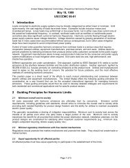
3.1 MODULATION CHARACTERISTICS<br />
The Modulation is GFSK (Gaussian Frequency Shift Keying) with a BT=0.5.<br />
The Modulation index must be between 0.28 and 0.35. A binary one is represented<br />
by a positive frequency deviation, and a binary zero is represented by a<br />
negative frequency deviation. The symbol timing shall be better than ±20 ppm.<br />
Transmit<br />
Frequency<br />
Ft<br />
Ft+fd<br />
Fmin+<br />
Figure 3.1: Figure 3-1 Actual transmit modulation.<br />
For each transmit channel, <strong>the</strong> minimum frequency deviation (Fmin = <strong>the</strong><br />
lesser <strong>of</strong> {Fmin+, Fmin-}) which corresponds to 1010 sequence shall be no<br />
smaller than ±80% <strong>of</strong> <strong>the</strong> frequency deviation (fd) which corresponds to a<br />
00001111 sequence.<br />
In addition, <strong>the</strong> minimum deviation shall never be smaller than 115 kHz.<br />
The zero crossing error is <strong>the</strong> time difference between <strong>the</strong> ideal symbol period<br />
and <strong>the</strong> measured crossing time. This shall be less than ± 1/8 <strong>of</strong> a symbol<br />
period.<br />
3.2 SPURIOUS EMISSIONS<br />
Ideal Zero Crossing<br />
Fmin-<br />
Zero Crossing Error<br />
Time<br />
The spurious emission, in-band and out-<strong>of</strong>-band, is measured with a frequency<br />
hopping transmitter hopping on a single frequency; this means that <strong>the</strong> syn<strong>the</strong>sizer<br />
must change frequency between receive slot and transmit slot, but<br />
always returns to <strong>the</strong> same transmit frequency.<br />
For <strong>the</strong> USA, FCC parts 15.247, 15.249, 15.205 and 15.209 are applicable regulations.<br />
For Japan, RCR STD-33 applies and, for Europe, ETSI 300 328.<br />
Transmitter Characteristics 29 November 1999 21<br />
Ft-fd
BLUETOOTH SPECIFICATION Version 1.0 B page 22 <strong>of</strong> 1082<br />
Radio <strong>Specification</strong><br />
3.2.1 In-band Spurious Emission<br />
Within <strong>the</strong> ISM band <strong>the</strong> transmitter shall pass a spectrum mask, given in<br />
Table 3.2. The spectrum must comply with <strong>the</strong> FCC’s 20-dB bandwidth definition<br />
stated below, and should be measured accordingly. In addition to <strong>the</strong> FCC<br />
requirement an adjacent channel power on adjacent channels with a difference<br />
in channel number <strong>of</strong> two or greater an adjacent channel power is defined. This<br />
adjacent channel power is defined as <strong>the</strong> sum <strong>of</strong> <strong>the</strong> measured power in a<br />
1 MHz channel. The transmitted power shall be measured in a 100 kHz bandwidth<br />
using maximum hold. The transmitter is transmitting on channel M and<br />
<strong>the</strong> adjacent channel power is measured on channel number N. The transmitter<br />
is sending a pseudo random data pattern throughout <strong>the</strong> test.<br />
Frequency <strong>of</strong>fset Transmit Power<br />
± 550 kHz -20 dBc<br />
|M-N| = 2<br />
|M-N| ≥ 3<br />
-20 dBm<br />
-40 dBm<br />
Table 3.2: Transmit Spectrum mask.<br />
Note: If <strong>the</strong> output power is less than 0dBm <strong>the</strong>n, wherever appropriate, <strong>the</strong> FCC’s 20 dB<br />
relative requirement overrules <strong>the</strong> absolute adjacent channel power requirement<br />
stated in <strong>the</strong> above table.<br />
“In any 100 kHz bandwidth outside <strong>the</strong> frequency band in which <strong>the</strong> spread spectrum intentional radiator<br />
is operating, <strong>the</strong> radio frequency power that is produced by <strong>the</strong> intentional radiator shall be at least 20 dB<br />
below that in <strong>the</strong> 100 kHz bandwidth within <strong>the</strong> band that contains <strong>the</strong> highest level <strong>of</strong> <strong>the</strong> desired power,<br />
based on ei<strong>the</strong>r an RF conducted or a radiated measurement. Attenuation below <strong>the</strong> general limits specified<br />
in § 15.209(a) is not required. In addition, radiated emissions which fall in <strong>the</strong> restricted bands, as<br />
defined in § 15.205(a), must also comply with <strong>the</strong> radiated emission limits specified in § 15.209(a) (see §<br />
15.205(c)).”<br />
FCC Part 15.247c<br />
Exceptions are allowed in up to three bands <strong>of</strong> 1 MHz width centered on a frequency<br />
which is an integer multiple <strong>of</strong> 1 MHz. They must, however, comply with<br />
an absolute value <strong>of</strong> –20 dBm.<br />
3.2.2 Out-<strong>of</strong>-Band Spurious Emission<br />
The measured power should be measured in a 100 kHz bandwidth.<br />
Frequency Band Operation mode Idle mode<br />
30 MHz - 1 GHz -36 dBm -57 dBm<br />
1 GHz – 12.75 GHz -30 dBm -47 dBm<br />
1.8 GHz – 1.9 GHz -47 dBm -47 dBm<br />
5.15 GHz – 5.3 GHz -47 dBm -47 dBm<br />
Table 3.3: Out-<strong>of</strong>-band spurious emission requirement<br />
22 29 November 1999 Transmitter Characteristics
BLUETOOTH SPECIFICATION Version 1.0 B page 23 <strong>of</strong> 1082<br />
Radio <strong>Specification</strong><br />
3.3 RADIO FREQUENCY TOLERANCE<br />
The transmitted initial center frequency accuracy must be ±75 kHz from F c .<br />
The initial frequency accuracy is defined as being <strong>the</strong> frequency accuracy<br />
before any information is transmitted. Note that <strong>the</strong> frequency drift requirement<br />
is not included in <strong>the</strong> ±75 kHz.<br />
The transmitter center frequency drift in a packet is specified in Table 3.4. The<br />
different packets are defined in <strong>the</strong> Baseband <strong>Specification</strong>.<br />
Type <strong>of</strong> Packet Frequency Drift<br />
One-slot packet ±25 kHz<br />
Three-slot packet ±40 kHz<br />
Five-slot packet ±40 kHz<br />
Maximum drift rate 1)<br />
Table 3.4: Frequency drift in a package<br />
400 Hz/µs<br />
Note 1. The maximum drift rate is allowed anywhere in a<br />
packet.<br />
Transmitter Characteristics 29 November 1999 23
BLUETOOTH SPECIFICATION Version 1.0 B page 24 <strong>of</strong> 1082<br />
Radio <strong>Specification</strong><br />
4 RECEIVER CHARACTERISTICS<br />
In order to measure <strong>the</strong> bit error rate performance; <strong>the</strong> equipment must have a<br />
“loop back” facility. The equipment sends back <strong>the</strong> decoded information. This<br />
facility is specified in <strong>the</strong> Test Mode <strong>Specification</strong>.<br />
The reference sensitivity level referred to in this chapter equals -70 dBm.<br />
4.1 ACTUAL SENSITIVITY LEVEL<br />
The actual sensitivity level is defined as <strong>the</strong> input level for which a raw bit error<br />
rate (BER) <strong>of</strong> 0.1% is met. The requirement for a <strong>Bluetooth</strong> receiver is an<br />
actual sensitivity level <strong>of</strong> –70 dBm or better. The receiver must achieve <strong>the</strong> –70<br />
dBm sensitivity level with any <strong>Bluetooth</strong> transmitter compliant to <strong>the</strong> transmitter<br />
specification specified in Section 3 on page 20.<br />
4.2 INTERFERENCE PERFORMANCE<br />
The interference performance on Co-channel and adjacent 1 MHz and 2 MHz are<br />
measured with <strong>the</strong> wanted signal 10 dB over <strong>the</strong> reference sensitivity level. On all<br />
o<strong>the</strong>r frequencies <strong>the</strong> wanted signal shall be 3 dB over <strong>the</strong> reference sensitivity<br />
level. Should <strong>the</strong> frequency <strong>of</strong> an interfering signal lie outside <strong>of</strong> <strong>the</strong> band 2400-<br />
2497 MHz, <strong>the</strong> out-<strong>of</strong>-band blocking specification (see Section 4.3 on page 25)<br />
shall apply. The interfering signal shall be <strong>Bluetooth</strong>-modulated (see section 4.8 on<br />
page 27). The BER shall be ≤ 0.1%. The signal to interference ratio shall be:<br />
Requirement Ratio<br />
Co-Channel interference, C/I co-channel 11 dB 1)<br />
Adjacent (1 MHz) interference, C/I 1MHz 0 dB 1<br />
Adjacent (2 MHz) interference, C/I 2MHz<br />
Adjacent (≥3 MHz) interference, C/I ≥3MHz<br />
Image frequency Interference 2) 3) , C/I Image<br />
Adjacent (1 MHz) interference to in-band image frequency,<br />
C/I Image±1MHz<br />
Table 4.1: Interference performance<br />
-30 dB<br />
-40 dB<br />
-9 dB 1<br />
-20 dB 1<br />
Note 1. These specifications are tentative and will be fixed within 18 months after <strong>the</strong><br />
release <strong>of</strong> <strong>the</strong> <strong>Bluetooth</strong> specification version 1.0. Implementations have to fulfil<br />
<strong>the</strong> final specification after a 3-years’ convergence period starting at <strong>the</strong> release <strong>of</strong><br />
<strong>the</strong> <strong>Bluetooth</strong> specification version 1.0. During <strong>the</strong> convergence period, devices<br />
need to achieve a co-channel interference resistance <strong>of</strong> +14 dB, an ACI (@1MHz)<br />
resistance <strong>of</strong> +4 dB, Image frequency interference resistance <strong>of</strong> –6 dB and an ACI<br />
to in-band image frequency resistance <strong>of</strong> –16 dB.<br />
Note 2. In-band image frequency<br />
Note 3. If <strong>the</strong> image frequency ≠ n*1 MHz, than <strong>the</strong> image reference frequency is defined<br />
as <strong>the</strong> closest n*1 MHz frequency.<br />
Note 4. If two adjacent channel specifications from Table 4.1 are applicable to <strong>the</strong> same<br />
channel, <strong>the</strong> more relaxed specification applies.<br />
24 29 November 1999 Receiver Characteristics
BLUETOOTH SPECIFICATION Version 1.0 B page 25 <strong>of</strong> 1082<br />
Radio <strong>Specification</strong><br />
These specifications are only to be tested at nominal temperature conditions<br />
with a receiver hopping on one frequency, meaning that <strong>the</strong> syn<strong>the</strong>sizer must<br />
change frequency between receive slot and transmit slot, but always return to<br />
<strong>the</strong> same receive frequency.<br />
Frequencies where <strong>the</strong> requirements are not met are called spurious response<br />
frequencies. Five spurious response frequencies are allowed at frequencies<br />
with a distance <strong>of</strong> ≥2 MHz from <strong>the</strong> wanted signal. On <strong>the</strong>se spurious response<br />
frequencies a relaxed interference requirement C/I = -17 dB shall be met.<br />
4.3 OUT-OF-BAND BLOCKING<br />
The Out <strong>of</strong> band blocking is measured with <strong>the</strong> wanted signal 3 dB over <strong>the</strong> reference<br />
sensitivity level. The interfering signal shall be a continuous wave signal.<br />
The BER shall be ≤ 0.1%. The Out <strong>of</strong> band blocking shall fulfil <strong>the</strong> following<br />
requirements:<br />
Interfering Signal<br />
Frequency<br />
30 MHz - 2000 MHz -10 dBm<br />
2000 - 2399 MHz -27 dBm<br />
2498 – 3000 MHz -27 dBm<br />
3000 MHz – 12.75 GHz -10 dBm<br />
Interfering Signal Power<br />
Level<br />
Table 4.2: Out <strong>of</strong> Band blocking requirements<br />
24 exceptions are permitted which are dependent upon <strong>the</strong> given receive channel<br />
frequency and are centered at a frequency which is an integer multiple <strong>of</strong> 1<br />
MHz. At 19 <strong>of</strong> <strong>the</strong>se spurious response frequencies a relaxed power level -50<br />
dBm <strong>of</strong> <strong>the</strong> interferer may used to achieve a BER <strong>of</strong> 0.1%. At <strong>the</strong> remaining 5<br />
spurious response frequencies <strong>the</strong> power level is arbitrary.<br />
4.4 INTERMODULATION CHARACTERISTICS<br />
The reference sensitivity performance, BER = 0.1%, shall be met under <strong>the</strong> following<br />
conditions.<br />
The wanted signal at frequency f 0 with a power level 6 dB over <strong>the</strong> reference<br />
sensitivity level.<br />
A static sine wave signal at f 1 with a power level <strong>of</strong> –39 dBm<br />
A <strong>Bluetooth</strong> modulated signal (see Section 4.8 on page 27) at f 2 with a<br />
power level <strong>of</strong> -39 dBm<br />
Such that f 0 =2f 1 -f 2 and ⎟ f 2 -f 1 ⎟ =n*1 MHz, where n can be 3, 4, or 5. The system<br />
must fulfil one <strong>of</strong> <strong>the</strong> three alternatives.<br />
Receiver Characteristics 29 November 1999 25
BLUETOOTH SPECIFICATION Version 1.0 B page 26 <strong>of</strong> 1082<br />
Radio <strong>Specification</strong><br />
4.5 MAXIMUM USABLE LEVEL<br />
The maximum usable input level <strong>the</strong> receiver shall operate at shall be better than –<br />
20 dBm. The BER shall be less or equal to 0,1% at –20* dBm input power.<br />
4.6 SPURIOUS EMISSIONS<br />
The spurious emission for a <strong>Bluetooth</strong> receiver shall not be more than:<br />
Frequency Band Requirement<br />
30 MHz - 1 GHz -57 dBm<br />
1 GHz – 12.75 GHz -47 dBm<br />
Table 4.3: Out-<strong>of</strong>-band spurious emission<br />
The measured power should be measured in a 100 kHz bandwidth.<br />
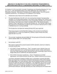
4.7 RECEIVER SIGNAL STRENGTH INDICATOR (OPTIONAL)<br />
A transceiver that wishes to take part in a power-controlled link must be able to<br />
measure its own receiver signal strength and determine if <strong>the</strong> transmitter on <strong>the</strong><br />
o<strong>the</strong>r side <strong>of</strong> <strong>the</strong> link should increase or decrease its output power level. A<br />
Receiver Signal Strength Indicator (RSSI) makes this possible.<br />
The way <strong>the</strong> power control is specified is to have a golden receive power. This<br />
golden receive power is defined as a range with a low limit and a high limit. The<br />
RSSI must have a minimum dynamic range equal to this range. The RSSI must<br />
have an absolute accuracy <strong>of</strong> ±4dB or better when <strong>the</strong> receive signal power is<br />
–60 dBm. In addition, a minimum range <strong>of</strong> 20±6 dB must be covered, starting<br />
from –60 dB and up (see Figure 4.1 on page 26).<br />
-60dBm±4<br />
Figure 4.1: RSSI dynamic range and accuracy<br />
20±6dB<br />
High limit<br />
Low limit<br />
26 29 November 1999 Receiver Characteristics
BLUETOOTH SPECIFICATION Version 1.0 B page 27 <strong>of</strong> 1082<br />
Radio <strong>Specification</strong><br />
4.8 REFERENCE INTERFERENCE-SIGNAL DEFINITION<br />
A <strong>Bluetooth</strong> modulated interfering signal is defined as:<br />
Modulation = GFSK<br />
Modulation index = 0.32±1%<br />
BT= 0.5±1%<br />
Bit Rate = 1 Mbps ±1 ppm<br />
Modulating Data = PRBS9<br />
Frequency accuracy better than ±1 ppm.<br />
Receiver Characteristics 29 November 1999 27
BLUETOOTH SPECIFICATION Version 1.0 B page 28 <strong>of</strong> 1082<br />
Radio <strong>Specification</strong><br />
5 APPENDIX A<br />
5.1 NOMINAL TEST CONDITIONS (NTC)<br />
5.1.1 Nominal temperature<br />
The nominal temperature conditions for tests shall be +15 to +35 o C. When it is<br />
impractical to carry out <strong>the</strong> test under this condition a note to this effect, stating<br />
<strong>the</strong> ambient temperature, shall be recorded. The actual value during <strong>the</strong> test<br />
shall be recorded in <strong>the</strong> test report.<br />
5.1.2 Nominal Power source<br />
5.1.2.1 Mains Voltage<br />
The nominal test voltage for equipment to be connected to <strong>the</strong> mains shall be<br />
<strong>the</strong> nominal mains voltage. The nominal voltage shall be declared voltage or<br />
any <strong>of</strong> <strong>the</strong> declared voltages for which <strong>the</strong> equipment was designed. The frequency<br />
<strong>of</strong> <strong>the</strong> test power source corresponding to <strong>the</strong> AC mains shall be within<br />
2% <strong>of</strong> <strong>the</strong> nominal frequency.<br />
5.1.2.2 Lead-acid battery power sources used in vehicles<br />
When radio equipment is intended for operation from <strong>the</strong> alternator-fed leadacid<br />
battery power sources which are standard in vehicles, <strong>the</strong>n <strong>the</strong> nominal<br />
test voltage shall be 1.1 times <strong>the</strong> nominal voltage <strong>of</strong> <strong>the</strong> battery (6V, 12V, etc.).<br />
5.1.2.3 O<strong>the</strong>r power sources<br />
For operation from o<strong>the</strong>r power sources or types <strong>of</strong> battery (primary or secondary),<br />
<strong>the</strong> nominal test voltage shall be as declared by <strong>the</strong> equipment manufacturer.<br />
This shall be recorded in <strong>the</strong> test report.<br />
28 29 November 1999 Appendix A
BLUETOOTH SPECIFICATION Version 1.0 B page 29 <strong>of</strong> 1082<br />
Radio <strong>Specification</strong><br />
5.2 EXTREME TEST CONDITIONS<br />
5.2.1 Extreme temperatures<br />
The extreme temperature range is defined as <strong>the</strong> largest temperature range<br />
given by <strong>the</strong> combination <strong>of</strong>:<br />
· The minimum temperature range 0 °C to +35 °C<br />
· The product operating temperature range declared by <strong>the</strong> manufacturer.<br />
This extreme temperature range and <strong>the</strong> declared operating temperature range<br />
shall be recorded in <strong>the</strong> test report.<br />
5.2.2 Extreme power source voltages<br />
Tests at extreme power source voltages specified below are not required when<br />
<strong>the</strong> equipment under test is designed for operation as part <strong>of</strong> and powered by<br />
ano<strong>the</strong>r system or piece <strong>of</strong> equipment. Where this is <strong>the</strong> case, <strong>the</strong> limit values<br />
<strong>of</strong> <strong>the</strong> host system or host equipment shall apply. The appropriate limit values<br />
shall be declared by <strong>the</strong> manufacturer and recorded in <strong>the</strong> test report.<br />
5.2.2.1 Mains voltage<br />
The extreme test voltage for equipment to be connected to an AC mains<br />
source shall be <strong>the</strong> nominal mains voltage ±10%.<br />
5.2.2.2 Lead-acid battery power source used on vehicles<br />
When radio equipment is intended for operation from <strong>the</strong> alternator-fed leadacid<br />
battery power sources which are standard in vehicles, <strong>the</strong>n extreme test<br />
voltage shall be 1.3 and 0.9 times <strong>the</strong> nominal voltage <strong>of</strong> <strong>the</strong> battery (6V, 12V<br />
etc.)<br />
5.2.2.3 Power sources using o<strong>the</strong>r types <strong>of</strong> batteries<br />
The lower extreme test voltage for equipment with power sources using <strong>the</strong> following<br />
types <strong>of</strong> battery, shall be<br />
a) for Leclanché, alkaline, or lithium type battery: 0.85 times <strong>the</strong><br />
nominal voltage <strong>of</strong> <strong>the</strong> battery<br />
b) for <strong>the</strong> mercury or nickel-cadmium types <strong>of</strong> battery: 0.9 times <strong>the</strong><br />
nominal voltage <strong>of</strong> <strong>the</strong> battery.<br />
In both cases, <strong>the</strong> upper extreme test voltage shall be 1.15 times <strong>the</strong> nominal<br />
voltage <strong>of</strong> <strong>the</strong> battery.<br />
Appendix A 29 November 1999 29
BLUETOOTH SPECIFICATION Version 1.0 B page 30 <strong>of</strong> 1082<br />
Radio <strong>Specification</strong><br />
5.2.2.4 O<strong>the</strong>r power sources<br />
For equipment using o<strong>the</strong>r power sources, or capable <strong>of</strong> being operated from a<br />
variety <strong>of</strong> power sources (primary or secondary), <strong>the</strong> extreme test voltages<br />
shall be those declared by <strong>the</strong> manufacturer. These shall be recorded in <strong>the</strong><br />
test report.<br />
30 29 November 1999 Appendix A
BLUETOOTH SPECIFICATION Version 1.0 B page 31 <strong>of</strong> 1082<br />
Radio <strong>Specification</strong><br />
6 APPENDIX B<br />
The Radio parameters shall be tested in <strong>the</strong> following conditions<br />
Parameter Temperature Power source<br />
Output Power ETC ETC<br />
Power control NTC NTC<br />
Modulation index ETC ETC<br />
Initial Carrier Frequency accuracy ETC ETC<br />
Carrier Frequency drift ETC ETC<br />
In-band spurious emissions ETC ETC<br />
Out-<strong>of</strong>-band Spurious Emissions ETC ETC<br />
Sensitivity ETC ETC<br />
Interference Performance NTC NTC<br />
Intermodulation Characteristics NTC NTC<br />
Out-<strong>of</strong>-band blocking NTC NTC<br />
Maximum Usable Level NTC NTC<br />
Receiver Signal Strength Indicator NTC NTC<br />
ETC = Extreme Test Conditions<br />
NTC = Nominal Test Conditions<br />
Appendix B 29 November 1999 31
BLUETOOTH SPECIFICATION Version 1.0 B page 32 <strong>of</strong> 1082<br />
Radio <strong>Specification</strong><br />
32 29 November 1999 Appendix B
Part B<br />
BASEBAND SPECIFICATION<br />
This document describes <strong>the</strong> specifications <strong>of</strong><br />
<strong>the</strong> <strong>Bluetooth</strong> link controller which carries out<br />
<strong>the</strong> baseband protocols and o<strong>the</strong>r low-level<br />
link routines.
BLUETOOTH SPECIFICATION Version 1.0 B page 34 <strong>of</strong> 1082<br />
Baseband <strong>Specification</strong><br />
34 29 November 1999
BLUETOOTH SPECIFICATION Version 1.0 B page 35 <strong>of</strong> 1082<br />
Baseband <strong>Specification</strong><br />
CONTENTS<br />
1 General Description ...........................................................................41<br />
2 Physical Channel................................................................................43<br />
2.1 Frequency Band and RF Channels............................................43<br />
2.2 Channel Definition......................................................................43<br />
2.3 Time Slots ..................................................................................43<br />
2.4 Modulation and Bit Rate.............................................................44<br />
3 Physical Links ....................................................................................45<br />
3.1 General ......................................................................................45<br />
3.2 SCO Link....................................................................................45<br />
3.3 ACL Link ....................................................................................46<br />
4 Packets................................................................................................47<br />
4.1 General Format..........................................................................47<br />
4.2 Access Code..............................................................................48<br />
4.2.1 Access code types ........................................................48<br />
4.2.2 Preamble .......................................................................49<br />
4.2.3 Sync Word.....................................................................49<br />
4.2.4 Trailer ............................................................................50<br />
4.3 Packet Header ...........................................................................51<br />
4.3.1 AM_ADDR.....................................................................51<br />
4.3.2 TYPE.............................................................................51<br />
4.3.3 FLOW............................................................................52<br />
4.3.4 ARQN............................................................................52<br />
4.3.5 SEQN ............................................................................52<br />
4.3.6 HEC...............................................................................52<br />
4.4 Packet Types .............................................................................54<br />
4.4.1 Common packet types...................................................55<br />
4.4.1.1 ID packet.........................................................55<br />
4.4.1.2 NULL packet ...................................................55<br />
4.4.1.3 POLL packet ...................................................55<br />
4.4.1.4 FHS packet .....................................................56<br />
4.4.1.5 DM1 packet.....................................................58<br />
4.4.2 SCO packets .................................................................58<br />
4.4.2.1 HV1 packet .....................................................58<br />
4.4.2.2 HV2 packet .....................................................59<br />
4.4.2.3 HV3 packet .....................................................59<br />
4.4.2.4 DV packet .......................................................59<br />
29 November 1999 35
BLUETOOTH SPECIFICATION Version 1.0 B page 36 <strong>of</strong> 1082<br />
Baseband <strong>Specification</strong><br />
4.4.3 ACL packets..................................................................60<br />
4.4.3.1 DM1 packet ....................................................60<br />
4.4.3.2 DH1 packet.....................................................60<br />
4.4.3.3 DM3 packet ....................................................60<br />
4.4.3.4 DH3 packet.....................................................60<br />
4.4.3.5 DM5 packet ....................................................61<br />
4.4.3.6 DH5 packet.....................................................61<br />
4.4.3.7 AUX1 packet...................................................61<br />
4.5 Payload Format .........................................................................62<br />
4.5.1 Voice field......................................................................62<br />
4.5.2 Data field.......................................................................62<br />
4.6 Packet Summary .......................................................................65<br />
5 Error Correction .................................................................................67<br />
5.1 FEC Code: Rate 1/3 ..................................................................67<br />
5.2 FEC Code: Rate 2/3 ..................................................................67<br />
5.3 ARQ Scheme.............................................................................68<br />
5.3.1 Unnumbered ARQ.........................................................68<br />
5.3.2 Retransmit filtering ........................................................70<br />
5.3.3 Flushing payloads .........................................................71<br />
5.3.4 Multi-slave considerations.............................................72<br />
5.3.5 Broadcast packets ........................................................72<br />
5.4 Error Checking...........................................................................73<br />
6 Logical Channels ...............................................................................77<br />
6.1 LC Channel (Link Control) .........................................................77<br />
6.2 LM Channel (Link Manager) ......................................................77<br />
6.3 UA/UI Channel (User Asynchronous/Isochronous data) ...........77<br />
6.4 US Channel (User Synchronous data) ......................................78<br />
6.5 Channel Mapping.......................................................................78<br />
7 Data Whitening...................................................................................79<br />
8 Transmit/Receive Routines ...............................................................81<br />
8.1 TX Routine.................................................................................81<br />
8.1.1 ACL traffic .....................................................................82<br />
8.1.2 SCO traffic.....................................................................83<br />
8.1.3 Mixed data/voice traffic .................................................83<br />
8.1.4 Default packet types .....................................................84<br />
8.2 RX Routine ................................................................................84<br />
8.3 Flow Control...............................................................................85<br />
8.3.1 Destination control ........................................................85<br />
8.3.2 Source control...............................................................85<br />
8.4 Bitstream Processes..................................................................86<br />
36 29 November 1999
BLUETOOTH SPECIFICATION Version 1.0 B page 37 <strong>of</strong> 1082<br />
Baseband <strong>Specification</strong><br />
9 Transmit/Receive Timing ...................................................................87<br />
9.1 Master/Slave Timing Synchronization........................................87<br />
9.2 Connection State .......................................................................88<br />
9.3 Return From Hold Mode.............................................................90<br />
9.4 Park Mode Wake-up ..................................................................90<br />
9.5 Page State .................................................................................91<br />
9.6 FHS Packet................................................................................91<br />
9.7 Multi-slave Operation .................................................................93<br />
10 Channel Control .................................................................................95<br />
10.1 Scope.........................................................................................95<br />
10.2 Master-Slave Definition..............................................................95<br />
10.3 <strong>Bluetooth</strong> Clock..........................................................................95<br />
10.4 Overview <strong>of</strong> States.....................................................................97<br />
10.5 Standby State ............................................................................98<br />
10.6 Access Procedures ....................................................................99<br />
10.6.1 General..........................................................................99<br />
10.6.2 Page scan ....................................................................99<br />
10.6.3 Page............................................................................101<br />
10.6.4 Page response procedures .........................................104<br />
10.6.4.1 Slave response .............................................105<br />
10.6.4.2 Master response ...........................................107<br />
10.7 Inquiry Procedures...................................................................108<br />
10.7.1 General........................................................................108<br />
10.7.2 Inquiry scan.................................................................109<br />
10.7.3 Inquiry..........................................................................110<br />
10.7.4 Inquiry response.......................................................... 111<br />
10.8 Connection State .....................................................................112<br />
10.8.1 Active mode.................................................................113<br />
10.8.2 Sniff mode ...................................................................114<br />
10.8.3 Hold mode...................................................................114<br />
10.8.4 Park mode...................................................................115<br />
10.8.4.1 Beacon channel ............................................115<br />
10.8.4.2 Beacon access window ................................117<br />
10.8.4.3 Parked slave synchronization .......................119<br />
10.8.4.4 Parking..........................................................120<br />
10.8.4.5 Master-activated unparking...........................120<br />
10.8.4.6 Slave-activated unparking ............................120<br />
10.8.4.7 Broadcast scan window ................................121<br />
10.8.5 Polling schemes ..........................................................121<br />
10.8.5.1 Polling in active mode...................................121<br />
10.8.5.2 Polling in park mode .....................................122<br />
29 November 1999 37
BLUETOOTH SPECIFICATION Version 1.0 B page 38 <strong>of</strong> 1082<br />
Baseband <strong>Specification</strong><br />
10.8.6 Slot reservation scheme..............................................122<br />
10.8.7 Broadcast scheme ......................................................122<br />
10.9 Scatternet ................................................................................122<br />
10.9.1 General .......................................................................122<br />
10.9.2 Inter-piconet communications .....................................123<br />
10.9.3 Master-slave switch.....................................................123<br />
11<br />
10.10 Power Management.................................................................125<br />
10.10.1 Packet handling ..........................................................125<br />
10.10.2 Slot occupancy............................................................125<br />
10.10.3 Low-power modes.......................................................125<br />
10.11 Link Supervision ......................................................................126<br />
Hop Selection ...................................................................................127<br />
11.1 General Selection Scheme ......................................................127<br />
11.2 Selection Kernel.......................................................................129<br />
11.2.1 First addition operation................................................130<br />
11.2.2 XOR operation ............................................................130<br />
11.2.3 Permutation operation.................................................131<br />
11.2.4 Second addition operation ..........................................133<br />
11.2.5 Register bank..............................................................133<br />
11.3 Control Word............................................................................133<br />
11.3.1 Page scan and Inquiry scan substates .......................135<br />
11.3.2 Page substate .............................................................135<br />
11.3.3 Page response............................................................136<br />
11.3.3.1 Slave response.............................................136<br />
11.3.3.2 Master response...........................................136<br />
11.3.4 Inquiry substate...........................................................137<br />
11.3.5 Inquiry response .........................................................137<br />
11.3.6 Connection state .........................................................138<br />
12 <strong>Bluetooth</strong> Audio ...............................................................................139<br />
12.1 LOG PCM CODEC ..................................................................139<br />
12.2 CVSD CODEC.........................................................................139<br />
12.3 Error Handling..........................................................................142<br />
12.4 General Audio Requirements ..................................................142<br />
12.4.1 Signal levels................................................................142<br />
12.4.2 CVSD audio quality.....................................................142<br />
38 29 November 1999
BLUETOOTH SPECIFICATION Version 1.0 B page 39 <strong>of</strong> 1082<br />
Baseband <strong>Specification</strong><br />
13 <strong>Bluetooth</strong> Addressing......................................................................143<br />
13.1 <strong>Bluetooth</strong> Device Address (BD_ADDR) ...................................143<br />
13.2 Access Codes ..........................................................................143<br />
13.2.1 Synchronization word definition...................................144<br />
13.2.2 Pseudo-random noise sequence generation...............146<br />
13.2.3 Reserved addresses for GIAC and DIAC....................147<br />
13.3 Active Member Address (AM_ADDR)......................................147<br />
13.4 Parked Member Address (PM_ADDR) ....................................148<br />
13.5 Access Request Address (AR_ADDR) ....................................148<br />
14 <strong>Bluetooth</strong> Security ...........................................................................149<br />
14.1 Random Number Generation...................................................150<br />
14.2 Key Management.....................................................................150<br />
14.2.1 Key types.....................................................................151<br />
14.2.2 Key generation and initialization..................................153<br />
14.2.2.1 Generation <strong>of</strong> initialization key, ....................153<br />
14.2.2.2 Au<strong>the</strong>ntication ...............................................154<br />
14.2.2.3 Generation <strong>of</strong> a unit key................................154<br />
14.2.2.4 Generation <strong>of</strong> a combination key ..................155<br />
14.2.2.5 Generating <strong>the</strong> encryption key......................156<br />
14.2.2.6 Point-to-multipoint configuration ...................157<br />
14.2.2.7 Modifying <strong>the</strong> link keys..................................157<br />
14.2.2.8 Generating a master key ..............................158<br />
14.3 Encryption ................................................................................159<br />
14.3.1 Encryption key size negotiation...................................160<br />
14.3.2 Encryption modes........................................................161<br />
14.3.3 Encryption concept......................................................161<br />
14.3.4 Encryption algorithm....................................................163<br />
14.3.4.1 The operation <strong>of</strong> <strong>the</strong> cipher...........................165<br />
14.3.5 LFSR initialization........................................................165<br />
14.3.6 Key stream sequence..................................................168<br />
14.4 Au<strong>the</strong>ntication ..........................................................................169<br />
14.4.1 Repeated attempts......................................................170<br />
14.5 The Au<strong>the</strong>ntication And Key-Generating Functions.................171<br />
14.5.1 The au<strong>the</strong>ntication function E1....................................171<br />
14.5.2 The functions Ar and A’r ..............................................173<br />
14.5.2.1 The round computations ...............................173<br />
14.5.2.2 The substitution boxes “e” and “l” .................174<br />
14.5.2.3 Key scheduling .............................................175<br />
14.5.3 E2-Key generation function for au<strong>the</strong>ntication ............175<br />
14.5.4 E3-Key generation function for encryption ..................177<br />
15 List <strong>of</strong> Figures...................................................................................179<br />
16 List <strong>of</strong> Tables ....................................................................................183<br />
29 November 1999 39
BLUETOOTH SPECIFICATION Version 1.0 B page 40 <strong>of</strong> 1082<br />
Baseband <strong>Specification</strong><br />
40 29 November 1999
BLUETOOTH SPECIFICATION Version 1.0 B page 41 <strong>of</strong> 1082<br />
Baseband <strong>Specification</strong><br />
1 GENERAL DESCRIPTION<br />
<strong>Bluetooth</strong> is a short-range radio link intended to replace <strong>the</strong> cable(s) connecting<br />
portable and/or fixed electronic devices. Key features are robustness, low<br />
complexity, low power, and low cost.<br />
<strong>Bluetooth</strong> operates in <strong>the</strong> unlicensed ISM band at 2.4 GHz. A frequency hop<br />
transceiver is applied to combat interference and fading. A shaped, binary FM<br />
modulation is applied to minimize transceiver complexity. The symbol rate is 1<br />
Ms/s. A slotted channel is applied with a nominal slot length <strong>of</strong> 625 μs. For full<br />
duplex transmission, a Time-Division Duplex (TDD) scheme is used. On <strong>the</strong><br />
channel, information is exchanged through packets. Each packet is transmitted<br />
on a different hop frequency. A packet nominally covers a single slot, but can<br />
be extended to cover up to five slots.<br />
The <strong>Bluetooth</strong> protocol uses a combination <strong>of</strong> circuit and packet switching.<br />
Slots can be reserved for synchronous packets. <strong>Bluetooth</strong> can support an<br />
asynchronous data channel, up to three simultaneous synchronous voice<br />
channels, or a channel which simultaneously supports asynchronous data and<br />
synchronous voice. Each voice channel supports a 64 kb/s synchronous<br />
(voice) channel in each direction. The asynchronous channel can support maximal<br />
723.2 kb/s asymmetric (and still up to 57.6 kb/s in <strong>the</strong> return direction), or<br />
433.9 kb/s symmetric.<br />
The <strong>Bluetooth</strong> system consists <strong>of</strong> a radio unit (see Radio <strong>Specification</strong>), a link<br />
control unit, and a support unit for link management and host terminal interface<br />
functions, see Figure 1.1 on page 41. The current document describes <strong>the</strong><br />
specifications <strong>of</strong> <strong>the</strong> <strong>Bluetooth</strong> link controller, which carries out <strong>the</strong> baseband<br />
protocols and o<strong>the</strong>r low-level link routines. Link layer messages for link set-up<br />
and control are defined in <strong>the</strong> Link Manager Protocol on page 185.<br />
2.4 GHz<br />
<strong>Bluetooth</strong><br />
radio<br />
<strong>Bluetooth</strong><br />
link<br />
controller<br />
Figure 1.1: Different functional blocks in <strong>the</strong> <strong>Bluetooth</strong> system<br />
<strong>Bluetooth</strong><br />
link<br />
manager<br />
& I/O<br />
The <strong>Bluetooth</strong> system provides a point-to-point connection (only two <strong>Bluetooth</strong><br />
units involved), or a point-to-multipoint connection, see Figure 1.2 on page 42.<br />
In <strong>the</strong> point-to-multipoint connection, <strong>the</strong> channel is shared among several<br />
<strong>Bluetooth</strong> units. Two or more units sharing <strong>the</strong> same channel form a piconet.<br />
One <strong>Bluetooth</strong> unit acts as <strong>the</strong> master <strong>of</strong> <strong>the</strong> piconet, whereas <strong>the</strong> o<strong>the</strong>r unit(s)<br />
General Description 29 November 1999 41<br />
host
BLUETOOTH SPECIFICATION Version 1.0 B page 42 <strong>of</strong> 1082<br />
Baseband <strong>Specification</strong><br />
acts as slave(s). Up to seven slaves can be active in <strong>the</strong> piconet. In addition,<br />
many more slaves can remain locked to <strong>the</strong> master in a so-called parked state.<br />
These parked slaves cannot be active on <strong>the</strong> channel, but remain synchronized<br />
to <strong>the</strong> master. Both for active and parked slaves, <strong>the</strong> channel access is<br />
controlled by <strong>the</strong> master.<br />
Multiple piconets with overlapping coverage areas form a scatternet. Each<br />
piconet can only have a single master. However, slaves can participate in different<br />
piconets on a time-division multiplex basis. In addition, a master in one<br />
piconet can be a slave in ano<strong>the</strong>r piconet. The piconets shall not be time- or<br />
frequency-synchronized. Each piconet has its own hopping channel.<br />
Master<br />
Slave<br />
a b c<br />
Figure 1.2: Piconets with a single slave operation (a), a multi-slave operation (b) and a scatternet<br />
operation (c).<br />
42 29 November 1999 General Description
BLUETOOTH SPECIFICATION Version 1.0 B page 43 <strong>of</strong> 1082<br />
Baseband <strong>Specification</strong><br />
2 PHYSICAL CHANNEL<br />
2.1 FREQUENCY BAND AND RF CHANNELS<br />
<strong>Bluetooth</strong> operates in <strong>the</strong> 2.4 GHz ISM band. Although globally available, <strong>the</strong><br />
exact location and <strong>the</strong> width <strong>of</strong> <strong>the</strong> band may differ by country. In <strong>the</strong> US and<br />
Europe, a band <strong>of</strong> 83.5 MHz width is available; in this band, 79 RF channels<br />
spaced 1 MHz apart are defined. In Japan, Spain, and France, a smaller band<br />
is available; in this band, 23 RF channels spaced 1 MHz apart are defined.<br />
Country Frequency Range RF Channels<br />
Europe * & USA<br />
Table 2.1: Available RF channels<br />
*. except Spain and France<br />
2.2 CHANNEL DEFINITION<br />
The channel is represented by a pseudo-random hopping sequence hopping<br />
through <strong>the</strong> 79 or 23 RF channels. The hopping sequence is unique for <strong>the</strong><br />
piconet and is determined by <strong>the</strong> <strong>Bluetooth</strong> device address <strong>of</strong> <strong>the</strong> master; <strong>the</strong><br />
phase in <strong>the</strong> hopping sequence is determined by <strong>the</strong> <strong>Bluetooth</strong> clock <strong>of</strong> <strong>the</strong><br />
master. The channel is divided into time slots where each slot corresponds to<br />
an RF hop frequency. Consecutive hops correspond to different RF hop frequencies.<br />
The nominal hop rate is 1600 hops/s. All <strong>Bluetooth</strong> units participating<br />
in <strong>the</strong> piconet are time- and hop-synchronized to <strong>the</strong> channel.<br />
2.3 TIME SLOTS<br />
2400 - 2483.5 MHz f = 2402 + k MHz k= 0,...,78<br />
Japan 2471 - 2497 MHz f = 2473 + k MHz k= 0,...,22<br />
Spain 2445 - 2475 MHz f = 2449 + k MHz k= 0,...,22<br />
France 2446.5 - 2483.5 MHz f = 2454 + k MHz k= 0,...,22<br />
The channel is divided into time slots, each 625 μs in length. The time slots are<br />
numbered according to <strong>the</strong> <strong>Bluetooth</strong> clock <strong>of</strong> <strong>the</strong> piconet master. The slot<br />
numbering ranges from 0 to 2 27 -1 and is cyclic with a cycle length <strong>of</strong> 2 27 .<br />
In <strong>the</strong> time slots, master and slave can transmit packets.<br />
A TDD scheme is used where master and slave alternatively transmit, see<br />
Figure 2.1 on page 44. The master shall start its transmission in evennumbered<br />
time slots only, and <strong>the</strong> slave shall start its transmission in oddnumbered<br />
time slots only. The packet start shall be aligned with <strong>the</strong> slot start.<br />
Packets transmitted by <strong>the</strong> master or <strong>the</strong> slave may extend over up to five time<br />
slots.<br />
Physical Channel 29 November 1999 43
BLUETOOTH SPECIFICATION Version 1.0 B page 44 <strong>of</strong> 1082<br />
Baseband <strong>Specification</strong><br />
The RF hop frequency shall remain fixed for <strong>the</strong> duration <strong>of</strong> <strong>the</strong> packet. For a<br />
single packet, <strong>the</strong> RF hop frequency to be used is derived from <strong>the</strong> current<br />
<strong>Bluetooth</strong> clock value. For a multi-slot packet, <strong>the</strong> RF hop frequency to be used<br />
for <strong>the</strong> entire packet is derived from <strong>the</strong> <strong>Bluetooth</strong> clock value in <strong>the</strong> first slot <strong>of</strong><br />
<strong>the</strong> packet. The RF hop frequency in <strong>the</strong> first slot after a multi-slot packet shall<br />
use <strong>the</strong> frequency as determined by <strong>the</strong> current <strong>Bluetooth</strong> clock value. Figure<br />
2.2 on page 44 illustrates <strong>the</strong> hop definition on single- and multi-slot packets. If<br />
a packet occupies more than one time slot, <strong>the</strong> hop frequency applied shall be<br />
<strong>the</strong> hop frequency as applied in <strong>the</strong> time slot where <strong>the</strong> packet transmission<br />
was started.<br />
Master<br />
Slave<br />
Figure 2.1: TDD and timing<br />
625 µs<br />
f(k)<br />
Figure 2.2: Multi-slot packets<br />
2.4 MODULATION AND BIT RATE<br />
f(k) f(k+1) f(k+2)<br />
625 µs<br />
f(k+1) f(k+2) f(k+3) f(k+4) f(k+5)<br />
f(k) f(k+3) f(k+4) f(k+5)<br />
f(k) f(k+5)<br />
f(k+6)<br />
f(k+6)<br />
f(k+6)<br />
The data transmitted has a symbol rate <strong>of</strong> 1 Ms/s. A Gaussian-shaped, binary FSK<br />
modulation is applied with a BT product <strong>of</strong> 0.5. A binary one is represented by a<br />
positive frequency deviation, a binary zero by a negative frequency deviation. The<br />
maximum frequency deviation shall be between 140 kHz and 175 kHz.<br />
44 29 November 1999 Physical Channel
BLUETOOTH SPECIFICATION Version 1.0 B page 45 <strong>of</strong> 1082<br />
Baseband <strong>Specification</strong><br />
3 PHYSICAL LINKS<br />
3.1 GENERAL<br />
Between master and slave(s), different types <strong>of</strong> links can be established. Two<br />
link types have been defined:<br />
• Synchronous Connection-Oriented (SCO) link<br />
• Asynchronous Connection-Less (ACL) link<br />
The SCO link is a point-to-point link between a master and a single slave in <strong>the</strong><br />
piconet. The master maintains <strong>the</strong> SCO link by using reserved slots at regular<br />
intervals. The ACL link is a point-to-multipoint link between <strong>the</strong> master and all<br />
<strong>the</strong> slaves participating on <strong>the</strong> piconet. In <strong>the</strong> slots not reserved for <strong>the</strong> SCO<br />
link(s), <strong>the</strong> master can establish an ACL link on a per-slot basis to any slave,<br />
including <strong>the</strong> slave(s) already engaged in an SCO link.<br />
3.2 SCO LINK<br />
The SCO link is a symmetric, point-to-point link between <strong>the</strong> master and a specific<br />
slave. The SCO link reserves slots and can <strong>the</strong>refore be considered as a<br />
circuit-switched connection between <strong>the</strong> master and <strong>the</strong> slave. The SCO link<br />
typically supports time-bounded information like voice. The master can support<br />
up to three SCO links to <strong>the</strong> same slave or to different slaves. A slave can support<br />
up to three SCO links from <strong>the</strong> same master, or two SCO links if <strong>the</strong> links<br />
originate from different masters. SCO packets are never retransmitted.<br />
The master will send SCO packets at regular intervals, <strong>the</strong> so-called SCO interval<br />
T SCO (counted in slots) to <strong>the</strong> slave in <strong>the</strong> reserved master-to-slave slots.<br />
The SCO slave is always allowed to respond with an SCO packet in <strong>the</strong> following<br />
slave-to-master slot unless a different slave was addressed in <strong>the</strong> previous<br />
master-to-slave slot. If <strong>the</strong> SCO slave fails to decode <strong>the</strong> slave address in <strong>the</strong><br />
packet header, it is still allowed to return an SCO packet in <strong>the</strong> reserved SCO<br />
slot.<br />
The SCO link is established by <strong>the</strong> master sending an SCO setup message via<br />
<strong>the</strong> LM protocol. This message will contain timing parameters such as <strong>the</strong> SCO<br />
interval T SCO and <strong>the</strong> <strong>of</strong>fset D SCO to specify <strong>the</strong> reserved slots.<br />
In order to prevent clock wrap-around problems, an initialization flag in <strong>the</strong> LMP<br />
setup message indicates whe<strong>the</strong>r initialization procedure 1 or 2 is being used.<br />
The slave shall apply <strong>the</strong> initialization method as indicated by <strong>the</strong> initialization<br />
flag. The master uses initialization 1 when <strong>the</strong> MSB <strong>of</strong> <strong>the</strong> current master clock<br />
(CLK 27) is 0; it uses initialization 2 when <strong>the</strong> MSB <strong>of</strong> <strong>the</strong> current master clock<br />
(CLK 27 ) is 1. The master-to-slave SCO slots reserved by <strong>the</strong> master and <strong>the</strong><br />
slave shall be initialized on <strong>the</strong> slots for which <strong>the</strong> clock satisfies <strong>the</strong> following<br />
equation:<br />
Physical Links 29 November 1999 45
BLUETOOTH SPECIFICATION Version 1.0 B page 46 <strong>of</strong> 1082<br />
Baseband <strong>Specification</strong><br />
CLK 27-1 mod T SCO = D SCO<br />
(CLK 27,CLK 26-1) mod T SCO = D SCO<br />
for initialization 1<br />
for initialization 2<br />
The slave-to-master SCO slots shall directly follow <strong>the</strong> reserved master-toslave<br />
SCO slots. After initialization, <strong>the</strong> clock value CLK(k+1) for <strong>the</strong> next master-to-slave<br />
SCO slot is found by adding <strong>the</strong> fixed interval T SCO to <strong>the</strong> clock<br />
value <strong>of</strong> <strong>the</strong> current master-to-slave SCO slot:<br />
CLK(k+1) = CLK(k) + T SCO<br />
3.3 ACL LINK<br />
In <strong>the</strong> slots not reserved for SCO links, <strong>the</strong> master can exchange packets with<br />
any slave on a per-slot basis. The ACL link provides a packet-switched connection<br />
between <strong>the</strong> master and all active slaves participating in <strong>the</strong> piconet.<br />
Both asynchronous and isochronous services are supported. Between a master<br />
and a slave only a single ACL link can exist. For most ACL packets, packet<br />
retransmission is applied to assure data integrity.<br />
A slave is permitted to return an ACL packet in <strong>the</strong> slave-to-master slot if and<br />
only if it has been addressed in <strong>the</strong> preceding master-to-slave slot. If <strong>the</strong> slave<br />
fails to decode <strong>the</strong> slave address in <strong>the</strong> packet header, it is not allowed to<br />
transmit.<br />
ACL packets not addressed to a specific slave are considered as broadcast<br />
packets and are read by every slave. If <strong>the</strong>re is no data to be sent on <strong>the</strong> ACL<br />
link and no polling is required, no transmission shall take place.<br />
46 29 November 1999 Physical Links
BLUETOOTH SPECIFICATION Version 1.0 B page 47 <strong>of</strong> 1082<br />
Baseband <strong>Specification</strong><br />
4 PACKETS<br />
4.1 GENERAL FORMAT<br />
The bit ordering when defining packets and messages in <strong>the</strong> Baseband<br />
<strong>Specification</strong>, follows <strong>the</strong> Little Endian format, i.e., <strong>the</strong> following rules apply:<br />
• The least significant bit (LSB) corresponds to ;<br />
• The LSB is <strong>the</strong> first bit sent over <strong>the</strong> air;<br />
• In illustrations, <strong>the</strong> LSB is shown on <strong>the</strong> left side;<br />
The baseband controller interprets <strong>the</strong> first bit arriving from a higher s<strong>of</strong>tware<br />
layer as b0 ; i.e. this is <strong>the</strong> first bit to be sent over <strong>the</strong> air. Fur<strong>the</strong>rmore, data<br />
fields generated internally at baseband level, such as <strong>the</strong> packet header fields<br />
and payload header length, are transmitted with <strong>the</strong> LSB first. For instance, a<br />
3-bit parameter X=3 is sent as b0b 1b = 110 over <strong>the</strong> air where 1 is sent first<br />
2<br />
and 0 is sent last.<br />
The data on <strong>the</strong> piconet channel is conveyed in packets. The general packet<br />
format is shown in Figure 4.1 on page 47. Each packet consists <strong>of</strong> 3 entities:<br />
<strong>the</strong> access code, <strong>the</strong> header, and <strong>the</strong> payload. In <strong>the</strong> figure, <strong>the</strong> number <strong>of</strong> bits<br />
per entity is indicated.<br />
LSB 72<br />
54 0 - 2745<br />
MSB<br />
ACCESS<br />
CODE<br />
HEADER<br />
Figure 4.1: Standard packet format.<br />
The access code and header are <strong>of</strong> fixed size: 72 bits and 54 bits respectively.<br />
The payload can range from zero to a maximum <strong>of</strong> 2745 bits. Different packet<br />
types have been defined. Packets may consist <strong>of</strong> <strong>the</strong> (shortened) access code<br />
only (see ID packet on page 55), <strong>of</strong> <strong>the</strong> access code − header, or <strong>of</strong> <strong>the</strong> access<br />
code − header − payload.<br />
Packets 29 November 1999 47<br />
b 0<br />
PAYLOAD
BLUETOOTH SPECIFICATION Version 1.0 B page 48 <strong>of</strong> 1082<br />
Baseband <strong>Specification</strong><br />
4.2 ACCESS CODE<br />
Each packet starts with an access code. If a packet header follows, <strong>the</strong> access<br />
code is 72 bits long, o<strong>the</strong>rwise <strong>the</strong> access code is 68 bits long. This access<br />
code is used for synchronization, DC <strong>of</strong>fset compensation and identification.<br />
The access code identifies all packets exchanged on <strong>the</strong> channel <strong>of</strong> <strong>the</strong> piconet:<br />
all packets sent in <strong>the</strong> same piconet are preceded by <strong>the</strong> same channel<br />
access code. In <strong>the</strong> receiver <strong>of</strong> <strong>the</strong> <strong>Bluetooth</strong> unit, a sliding correlator correlates<br />
against <strong>the</strong> access code and triggers when a threshold is exceeded. This trigger<br />
signal is used to determine <strong>the</strong> receive timing.<br />
The access code is also used in paging and inquiry procedures. In this case,<br />
<strong>the</strong> access code itself is used as a signalling message and nei<strong>the</strong>r a header<br />
nor a payload is present.<br />
The access code consists <strong>of</strong> a preamble, a sync word, and possibly a trailer,<br />
see Figure 4.2 on page 48. For details see Section 4.2.1 on page 48.<br />
LSB<br />
4<br />
PREAMBLE<br />
Figure 4.2: Access code format<br />
4.2.1 Access code types<br />
There are three different types <strong>of</strong> access codes defined:<br />
• Channel Access Code (CAC)<br />
• Device Access Code (DAC)<br />
• Inquiry Access Code (IAC)<br />
64<br />
SYNC WORD<br />
4 MSB<br />
TRAILER<br />
The respective access code types are used for a <strong>Bluetooth</strong> unit in different<br />
operating modes. The channel access code identifies a piconet. This code is<br />
included in all packets exchanged on <strong>the</strong> piconet channel. The device access<br />
code is used for special signalling procedures, e.g., paging and response to<br />
paging. For <strong>the</strong> inquiry access code <strong>the</strong>re are two variations. A general inquiry<br />
access code (GIAC) is common to all devices. The GIAC can be used to discover<br />
which o<strong>the</strong>r <strong>Bluetooth</strong> units are in range. The dedicated inquiry access<br />
code (DIAC) is common for a dedicated group <strong>of</strong> <strong>Bluetooth</strong> units that share a<br />
common characteristic. The DIAC can be used to discover only <strong>the</strong>se dedicated<br />
<strong>Bluetooth</strong> units in range.<br />
The CAC consists <strong>of</strong> a preamble, sync word, and trailer and its total length is<br />
72 bits. When used as self-contained messages without a header, <strong>the</strong> DAC<br />
and IAC do not include <strong>the</strong> trailer bits and are <strong>of</strong> length 68 bits.<br />
48 29 November 1999 Packets
BLUETOOTH SPECIFICATION Version 1.0 B page 49 <strong>of</strong> 1082<br />
Baseband <strong>Specification</strong><br />
The different access code types use different Lower Address Parts (LAPs) to<br />
construct <strong>the</strong> sync word. The LAP field <strong>of</strong> <strong>the</strong> BD address is explained in Section<br />
13.1 on page 143. A summary <strong>of</strong> <strong>the</strong> different access code types can be<br />
found in Table 4.1 on page 49.<br />
Code type LAP Code length Comments<br />
CAC Master 72<br />
DAC Paged unit 68/72 *<br />
GIAC Reserved 68/72*<br />
DIAC Dedicated 68/72*<br />
Table 4.1: Summary <strong>of</strong> access code types.<br />
*. length 72 is only used in combination with FHS packets<br />
4.2.2 Preamble<br />
The preamble is a fixed zero-one pattern <strong>of</strong> 4 symbols used to facilitate DC<br />
compensation. The sequence is ei<strong>the</strong>r 1010 or 0101, depending whe<strong>the</strong>r <strong>the</strong><br />
LSB <strong>of</strong> <strong>the</strong> following sync word is 1 or 0, respectively. The preamble is shown<br />
in Figure 4.3 on page 49.<br />
LSB MSB LSB LSB MSB LSB<br />
1 0 1 0 1<br />
preamble sync word<br />
Figure 4.3: Preamble<br />
4.2.3 Sync Word<br />
0 1 0 1 0<br />
See also Section 13.2<br />
on page 143<br />
preamble sync word<br />
The sync word is a 64-bit code word derived from a 24 bit address (LAP); for<br />
<strong>the</strong> CAC <strong>the</strong> master’s LAP is used; for <strong>the</strong> GIAC and <strong>the</strong> DIAC, reserved, dedicated<br />
LAPs are used; for <strong>the</strong> DAC, <strong>the</strong> slave unit LAP is used. The construction<br />
guarantees large Hamming distance between sync words based on different<br />
LAPs. In addition, <strong>the</strong> good autocorrelation properties <strong>of</strong> <strong>the</strong> sync word improve<br />
on <strong>the</strong> timing synchronization process. The derivation <strong>of</strong> <strong>the</strong> sync word is<br />
described in Section 13.2 on page 143<br />
Packets 29 November 1999 49
BLUETOOTH SPECIFICATION Version 1.0 B page 50 <strong>of</strong> 1082<br />
Baseband <strong>Specification</strong><br />
4.2.4 Trailer<br />
The trailer is appended to <strong>the</strong> sync word as soon as <strong>the</strong> packet header follows<br />
<strong>the</strong> access code. This is typically <strong>the</strong> case with <strong>the</strong> CAC, but <strong>the</strong> trailer is also<br />
used in <strong>the</strong> DAC and IAC when <strong>the</strong>se codes are used in FHS packets<br />
exchanged during page response and inquiry response procedures.<br />
The trailer is a fixed zero-one pattern <strong>of</strong> four symbols. The trailer toge<strong>the</strong>r with<br />
<strong>the</strong> three MSBs <strong>of</strong> <strong>the</strong> syncword form a 7-bit pattern <strong>of</strong> alternating ones and<br />
zeroes which may be used for extended DC compensation. The trailer<br />
sequence is ei<strong>the</strong>r 1010 or 0101 depending on whe<strong>the</strong>r <strong>the</strong> MSB <strong>of</strong> <strong>the</strong> sync<br />
word is 0 or 1, respectively. The choice <strong>of</strong> trailer is illustrated in Figure 4.4 on<br />
page 50.<br />
MSB LSB MSB MSB LSB MSB<br />
- - - - 0<br />
1 0 1 0<br />
sync word trailer<br />
a)<br />
- - - - 1<br />
sync word trailer<br />
Figure 4.4: Trailer in CAC when MSB <strong>of</strong> sync word is 0 (a), and when MSB <strong>of</strong> sync word is 1 (b).<br />
50 29 November 1999 Packets<br />
b)<br />
0 1 0 1
BLUETOOTH SPECIFICATION Version 1.0 B page 51 <strong>of</strong> 1082<br />
Baseband <strong>Specification</strong><br />
4.3 PACKET HEADER<br />
The header contains link control (LC) information and consists <strong>of</strong> 6 fields:<br />
• AM_ADDR: 3- bit active member address<br />
• TYPE: 4-bit type code<br />
• FLOW: 1-bit flow control<br />
• ARQN: 1-bit acknowledge indication<br />
• SEQN: 1-bit sequence number<br />
• HEC: 8-bit header error check<br />
The total header, including <strong>the</strong> HEC, consists <strong>of</strong> 18 bits, see Figure 4.5 on page<br />
51, and is encoded with a rate 1/3 FEC (not shown but described in Section 5.1<br />
on page 67) resulting in a 54-bit header. Note that <strong>the</strong> AM_ADDR and TYPE<br />
fields are sent with <strong>the</strong>ir LSB first. The function <strong>of</strong> <strong>the</strong> different fields will be<br />
explained next.<br />
LSB<br />
3<br />
AM_ADDR<br />
Figure 4.5: Header format.<br />
4.3.1 AM_ADDR<br />
The AM_ADDR represents a member address and is used to distinguish<br />
between <strong>the</strong> active members participating on <strong>the</strong> piconet. In a piconet, one or<br />
more slaves are connected to a single master. To identify each slave separately,<br />
each slave is assigned a temporary 3-bit address to be used when it is<br />
active. Packets exchanged between <strong>the</strong> master and <strong>the</strong> slave all carry <strong>the</strong><br />
AM_ADDR <strong>of</strong> this slave; that is, <strong>the</strong> AM_ADDR <strong>of</strong> <strong>the</strong> slave is used in both<br />
master-to-slave packets and in <strong>the</strong> slave-to-master packets. The all-zero<br />
address is reserved for broadcasting packets from <strong>the</strong> master to <strong>the</strong> slaves.<br />
An exception is <strong>the</strong> FHS packet which may use <strong>the</strong> all-zero member address<br />
but is not a broadcast message (Section 4.4.1.4 on page 56). Slaves that are<br />
disconnected or parked give up <strong>the</strong>ir AM_ADDR. A new AM_ADDR has to be<br />
assigned when <strong>the</strong>y re-enter <strong>the</strong> piconet.<br />
4.3.2 TYPE<br />
4<br />
TYPE<br />
1<br />
1<br />
Sixteen different types <strong>of</strong> packets can be distinguished. The 4-bit TYPE code<br />
specifies which packet type is used. Important to note is that <strong>the</strong> interpretation<br />
<strong>of</strong> <strong>the</strong> TYPE code depends on <strong>the</strong> physical link type associated with <strong>the</strong><br />
packet. First, it shall be determined whe<strong>the</strong>r <strong>the</strong> packet is sent on an SCO link<br />
or an ACL link. Then it can be determined which type <strong>of</strong> SCO packet or ACL<br />
packet has been received. The TYPE code also reveals how many slots <strong>the</strong><br />
current packet will occupy. This allows <strong>the</strong> non-addressed receivers to refrain<br />
Packets 29 November 1999 51<br />
1<br />
FLOW ARQN SEQN<br />
8<br />
HEC<br />
MSB
BLUETOOTH SPECIFICATION Version 1.0 B page 52 <strong>of</strong> 1082<br />
Baseband <strong>Specification</strong><br />
from listening to <strong>the</strong> channel for <strong>the</strong> duration <strong>of</strong> <strong>the</strong> remaining slots. In Section<br />
4.4 on page 54, each packet type will be described in more detail.<br />
4.3.3 FLOW<br />
This bit is used for flow control <strong>of</strong> packets over <strong>the</strong> ACL link. When <strong>the</strong> RX<br />
buffer for <strong>the</strong> ACL link in <strong>the</strong> recipient is full and is not emptied, a STOP indication<br />
(FLOW=0) is returned to stop <strong>the</strong> transmission <strong>of</strong> data temporarily. Note,<br />
that <strong>the</strong> STOP signal only concerns ACL packets. Packets including only link<br />
control information (ID, POLL and NULL packets) or SCO packets can still be<br />
received. When <strong>the</strong> RX buffer is empty, a GO indication (FLOW=1) is returned.<br />
When no packet is received, or <strong>the</strong> received header is in error, a GO is<br />
assumed implicitly.<br />
4.3.4 ARQN<br />
The 1-bit acknowledgment indication ARQN is used to inform <strong>the</strong> source <strong>of</strong> a<br />
successful transfer <strong>of</strong> payload data with CRC, and can be positive acknowledge<br />
ACK or negative acknowledge NAK. If <strong>the</strong> reception was successful, an<br />
ACK (ARQN=1) is returned, o<strong>the</strong>rwise a NAK (ARQN=0) is returned. When no<br />
return message regarding acknowledge is received, a NAK is assumed implicitly.<br />
NAK is also <strong>the</strong> default return information.<br />
The ARQN is piggy-backed in <strong>the</strong> header <strong>of</strong> <strong>the</strong> return packet. The success <strong>of</strong><br />
<strong>the</strong> reception is checked by means <strong>of</strong> a cyclic redundancy check (CRC) code.<br />
An unnumbered ARQ scheme which means that <strong>the</strong> ARQN relates to <strong>the</strong> latest<br />
received packet from <strong>the</strong> same source, is used. See Section 5.3 on page 68 for<br />
initialization and usage <strong>of</strong> this bit.<br />
4.3.5 SEQN<br />
The SEQN bit provides a sequential numbering scheme to order <strong>the</strong> data<br />
packet stream. For each new transmitted packet that contains data with CRC,<br />
<strong>the</strong> SEQN bit is inverted. This is required to filter out retransmissions at <strong>the</strong><br />
destination; if a retransmission occurs due to a failing ACK, <strong>the</strong> destination<br />
receives <strong>the</strong> same packet twice. By comparing <strong>the</strong> SEQN <strong>of</strong> consecutive packets,<br />
correctly received retransmissions can be discarded. The SEQN has to be<br />
added due to a lack <strong>of</strong> packet numbering in <strong>the</strong> unnumbered ARQ scheme.<br />
See section 5.3.2 on page 70 for initialization and usage <strong>of</strong> <strong>the</strong> SEQN bit. For<br />
broadcast packets, a modified sequencing method is used, see Section 5.3.5<br />
on page 72.<br />
4.3.6 HEC<br />
Each header has a header-error-check to check <strong>the</strong> header integrity. The HEC<br />
consists <strong>of</strong> an 8-bit word generated by <strong>the</strong> polynomial 647 (octal representation).<br />
Before generating <strong>the</strong> HEC, <strong>the</strong> HEC generator is initialized with an 8-bit<br />
value. For FHS packets sent in master page response state, <strong>the</strong> slave upper<br />
52 29 November 1999 Packets
BLUETOOTH SPECIFICATION Version 1.0 B page 53 <strong>of</strong> 1082<br />
Baseband <strong>Specification</strong><br />
address part (UAP) is used. For FHS packets sent in inquiry response, <strong>the</strong><br />
default check initialization (DCI, see Section 5.4) is used. In all o<strong>the</strong>r cases, <strong>the</strong><br />
UAP <strong>of</strong> <strong>the</strong> master device is used. For <strong>the</strong> definition <strong>of</strong> <strong>Bluetooth</strong> device<br />
addresses, see Section 13.1 on page 143.<br />
After <strong>the</strong> initialization, a HEC is calculated for <strong>the</strong> 10 header bits. Before checking<br />
<strong>the</strong> HEC, <strong>the</strong> receiver must initialize <strong>the</strong> HEC check circuitry with <strong>the</strong> proper<br />
8-bit UAP (or DCI). If <strong>the</strong> HEC does not check, <strong>the</strong> entire packet is disregarded.<br />
More information can be found in Section 5.4 on page 73.<br />
Packets 29 November 1999 53
BLUETOOTH SPECIFICATION Version 1.0 B page 54 <strong>of</strong> 1082<br />
Baseband <strong>Specification</strong><br />
4.4 PACKET TYPES<br />
The packets used on <strong>the</strong> piconet are related to <strong>the</strong> physical links <strong>the</strong>y are used in.<br />
Up to now, two physical links are defined: <strong>the</strong> SCO link and <strong>the</strong> ACL link. For each<br />
<strong>of</strong> <strong>the</strong>se links, 12 different packet types can be defined. Four control packets will be<br />
common to all link types: <strong>the</strong>ir TYPE code is unique irrespective <strong>of</strong> <strong>the</strong> link type.<br />
To indicate <strong>the</strong> different packets on a link, <strong>the</strong> 4-bit TYPE code is used. The<br />
packet types have been divided into four segments. The first segment is<br />
reserved for <strong>the</strong> four control packets common to all physical link types; all four<br />
packet types have been defined. The second segment is reserved for packets<br />
occupying a single time slot; six packet types have been defined. The third segment<br />
is reserved for packets occupying three time slots; two packet types have<br />
been defined. The fourth segment is reserved for packets occupying five time<br />
slots; two packet types have been defined. The slot occupancy is reflected in <strong>the</strong><br />
segmentation and can directly be derived from <strong>the</strong> type code. Table 4.2 on page<br />
54 summarizes <strong>the</strong> packets defined so far for <strong>the</strong> SCO and ACL link types.<br />
Segment<br />
1<br />
2<br />
3<br />
4<br />
TYPE code<br />
b 3b 2b 1b 0 Slot occupancy SCO link ACL link<br />
0000 1 NULL NULL<br />
0001 1 POLL POLL<br />
0010 1 FHS FHS<br />
0011 1 DM1 DM1<br />
0100 1 undefined DH1<br />
0101 1 HV1 undefined<br />
0110 1 HV2 undefined<br />
0111 1 HV3 undefined<br />
1000 1 DV undefined<br />
1001 1 undefined AUX1<br />
1010 3 undefined DM3<br />
1011 3 undefined DH3<br />
1100 3 undefined undefined<br />
1101 3 undefined undefined<br />
1110 5 undefined DM5<br />
1111 5 undefined DH5<br />
Table 4.2: Packets defined for SCO and ACL link types<br />
54 29 November 1999 Packets
BLUETOOTH SPECIFICATION Version 1.0 B page 55 <strong>of</strong> 1082<br />
Baseband <strong>Specification</strong><br />
4.4.1 Common packet types<br />
There are five common packets. In addition to <strong>the</strong> types listed in segment 1 <strong>of</strong><br />
<strong>the</strong> previous table, <strong>the</strong>re is <strong>the</strong> ID packet not listed. Each packet will now be<br />
examined in more detail.<br />
4.4.1.1 ID packet<br />
The identity or ID packet consists <strong>of</strong> <strong>the</strong> device access code (DAC) or inquiry<br />
access code (IAC). It has a fixed length <strong>of</strong> 68 bits. It is a very robust packet<br />
since <strong>the</strong> receiver uses a bit correlator to match <strong>the</strong> received packet to <strong>the</strong><br />
known bit sequence <strong>of</strong> <strong>the</strong> ID packet. The packet is used, for example, in paging,<br />
inquiry, and response routines.<br />
4.4.1.2 NULL packet<br />
The NULL packet has no payload and <strong>the</strong>refore consists <strong>of</strong> <strong>the</strong> channel access<br />
code and packet header only. Its total (fixed) length is 126 bits. The NULL<br />
packet is used to return link information to <strong>the</strong> source regarding <strong>the</strong> success <strong>of</strong><br />
<strong>the</strong> previous transmission (ARQN), or <strong>the</strong> status <strong>of</strong> <strong>the</strong> RX buffer (FLOW). The<br />
NULL packet itself does not have to be acknowledged.<br />
4.4.1.3 POLL packet<br />
The POLL packet is very similar to <strong>the</strong> NULL packet. It does not have a payload<br />
ei<strong>the</strong>r. In contrast to <strong>the</strong> NULL packet, it requires a confirmation from <strong>the</strong><br />
recipient. It is not a part <strong>of</strong> <strong>the</strong> ARQ scheme. The POLL packet does not affect<br />
<strong>the</strong> ARQN and SEQN fields. Upon reception <strong>of</strong> a POLL packet <strong>the</strong> slave must<br />
respond with a packet. This return packet is an implicit acknowledgement <strong>of</strong><br />
<strong>the</strong> POLL packet. This packet can be used by <strong>the</strong> master in a piconet to poll <strong>the</strong><br />
slaves, which must <strong>the</strong>n respond even if <strong>the</strong>y do not have information to send.<br />
Packets 29 November 1999 55
BLUETOOTH SPECIFICATION Version 1.0 B page 56 <strong>of</strong> 1082<br />
Baseband <strong>Specification</strong><br />
4.4.1.4 FHS packet<br />
The FHS packet is a special control packet revealing, among o<strong>the</strong>r things, <strong>the</strong><br />
<strong>Bluetooth</strong> device address and <strong>the</strong> clock <strong>of</strong> <strong>the</strong> sender. The payload contains<br />
144 information bits plus a 16-bit CRC code. The payload is coded with a rate<br />
2/3 FEC which brings <strong>the</strong> gross payload length to 240 bits. The FHS packet<br />
covers a single time slot.<br />
Figure 4.6 on page 56 illustrates <strong>the</strong> format and contents <strong>of</strong> <strong>the</strong> FHS payload.<br />
The payload consists <strong>of</strong> eleven fields. The FHS packet is used in page master<br />
response, inquiry response and in master slave switch. In page master<br />
response or master slave switch, it is retransmitted until its reception is<br />
acknowledged or a timeout has exceeded. In inquiry response, <strong>the</strong> FHS packet<br />
is not acknowledged. The FHS packet contains real-time clock information.<br />
This clock information is updated before each retransmission. The retransmission<br />
<strong>of</strong> <strong>the</strong> FHS payload is thus somewhat different from <strong>the</strong> retransmission <strong>of</strong><br />
ordinary data payloads where <strong>the</strong> same payload is used for each retransmission.<br />
The FHS packet is used for frequency hop synchronization before <strong>the</strong><br />
piconet channel has been established, or when an existing piconet changes to<br />
a new piconet. In <strong>the</strong> former case, <strong>the</strong> recipient has not been assigned an<br />
active member address yet, in which case <strong>the</strong> AM_ADDR field in <strong>the</strong> FHS<br />
packet header is set to all-zeroes; however, <strong>the</strong> FHS packet should not be<br />
considered as a broadcast packet. In <strong>the</strong> latter case <strong>the</strong> slave already has an<br />
AM_ADDR in <strong>the</strong> existing piconet, which is <strong>the</strong>n used in <strong>the</strong> FHS packet<br />
header.<br />
Figure 4.6: Format <strong>of</strong> <strong>the</strong> FHS payload<br />
Each field is described in more detail below:<br />
Parity bits<br />
LAP<br />
Undefined<br />
SR<br />
LSB MSB<br />
34 24 2 2 2 8 16 24 3 26 3<br />
Parity bits LAP<br />
Un-<br />
SR SP UAP NAP<br />
defined<br />
This 34-bit field contains <strong>the</strong> parity bits that form <strong>the</strong> first part <strong>of</strong> <strong>the</strong> sync<br />
word <strong>of</strong> <strong>the</strong> access code <strong>of</strong> <strong>the</strong> unit that sends <strong>the</strong> FHS packet. These bits<br />
are derived from <strong>the</strong> LAP as described in section 13.2 on page 143.<br />
This 24-bit field contains <strong>the</strong> lower address part <strong>of</strong> <strong>the</strong> unit that sends <strong>the</strong><br />
FHS packet.<br />
This 2-bit field is reserved for future use and shall be set to zero.<br />
This 2-bit field is <strong>the</strong> scan repetition field and indicates <strong>the</strong> interval between two<br />
consecutive page scan windows, see also Table 4.4 and Table 10.1 on page 101<br />
Table 4.3: Description <strong>of</strong> <strong>the</strong> FHS payload<br />
Class <strong>of</strong><br />
device<br />
AM_<br />
ADDR CLK 27-2<br />
Page<br />
scan<br />
mode<br />
56 29 November 1999 Packets
BLUETOOTH SPECIFICATION Version 1.0 B page 57 <strong>of</strong> 1082<br />
Baseband <strong>Specification</strong><br />
SP<br />
UAP<br />
NAP<br />
Class <strong>of</strong><br />
device<br />
AM_ADDR<br />
CLK 27-2<br />
Page scan<br />
mode<br />
This 2-bit field is <strong>the</strong> scan period field and indicates <strong>the</strong> period in which <strong>the</strong><br />
mandatory page scan mode is applied after transmission <strong>of</strong> an inquiry<br />
response message, see also Table 4.5 and Table 10.6 on page 112.<br />
This 8-bit field contains <strong>the</strong> upper address part <strong>of</strong> <strong>the</strong> unit that sends <strong>the</strong><br />
FHS packet.<br />
This 16-bit field contains <strong>the</strong> non-significant address part <strong>of</strong> <strong>the</strong> unit that<br />
sends <strong>the</strong> FHS packet (see also section 13.1 on page 143 for LAP, UAP,<br />
and NAP).<br />
This 24-bit field contains <strong>the</strong> class <strong>of</strong> device <strong>of</strong> <strong>the</strong> unit that sends <strong>the</strong> FHS<br />
packet. The class <strong>of</strong> device has not been defined yet.<br />
This 3-bit field contains <strong>the</strong> member address <strong>the</strong> recipient shall use if <strong>the</strong><br />
FHS packet is used at call setup or master-slave switch. A slave responding<br />
to a master or a unit responding to an inquiry request message shall include<br />
an all-zero AM_ADDR field if it sends <strong>the</strong> FHS packet.<br />
This 26-bit field contains <strong>the</strong> value <strong>of</strong> <strong>the</strong> native system clock <strong>of</strong> <strong>the</strong> unit that<br />
sends <strong>the</strong> FHS packet, sampled at <strong>the</strong> beginning <strong>of</strong> <strong>the</strong> transmission <strong>of</strong> <strong>the</strong><br />
access code <strong>of</strong> this FHS packet. This clock value has a resolution <strong>of</strong><br />
1.25ms (two-slot interval). For each new transmission, this field is updated<br />
so that it accurately reflects <strong>the</strong> real-time clock value.<br />
This 3-bit field indicates which scan mode is used by default by <strong>the</strong> sender<br />
<strong>of</strong> <strong>the</strong> FHS packet. The interpretation <strong>of</strong> <strong>the</strong> page scan mode is illustrated in<br />
Table 4.6. Currently, <strong>the</strong> standard supports one mandatory scan mode and<br />
up to three optional scan modes (see also “Appendix VII” on page 999).<br />
Table 4.3: Description <strong>of</strong> <strong>the</strong> FHS payload<br />
SR bit format b 1b 0 SR mode<br />
00 R0<br />
01 R1<br />
10 R2<br />
11 reserved<br />
Table 4.4: Contents <strong>of</strong> SR field<br />
SP bit format b 1 b 0 SP mode<br />
00 P0<br />
01 P1<br />
10 P2<br />
11 reserved<br />
Table 4.5: Contents <strong>of</strong> SP field<br />
Packets 29 November 1999 57
BLUETOOTH SPECIFICATION Version 1.0 B page 58 <strong>of</strong> 1082<br />
Baseband <strong>Specification</strong><br />
Bit format b 2 b 1 b 0 Page scan mode<br />
000 Mandatory scan mode<br />
001 Optional scan mode I<br />
010 Optional scan mode II<br />
011 Optional scan mode III<br />
100 Reserved for future use<br />
101 Reserved for future use<br />
110 Reserved for future use<br />
111 Reserved for future use<br />
Table 4.6: Contents <strong>of</strong> page scan mode field<br />
The LAP, UAP, and NAP toge<strong>the</strong>r form <strong>the</strong> 48-bit <strong>IEEE</strong> address <strong>of</strong> <strong>the</strong> unit that<br />
sends <strong>the</strong> FHS packet. Using <strong>the</strong> parity bits and <strong>the</strong> LAP, <strong>the</strong> recipient can<br />
directly construct <strong>the</strong> channel access code <strong>of</strong> <strong>the</strong> sender <strong>of</strong> <strong>the</strong> FHS packet.<br />
4.4.1.5 DM1 packet<br />
DM1 serves as part <strong>of</strong> segment 1 in order to support control messages in any<br />
link type. However, it can also carry regular user data. Since <strong>the</strong> DM1 packet is<br />
recognized on <strong>the</strong> SCO link, it can interrupt <strong>the</strong> synchronous information to<br />
send control information. Since <strong>the</strong> DM1 packet can be regarded as an ACL<br />
packet, it will be discussed in Section 4.4.3 on page 60.<br />
4.4.2 SCO packets<br />
SCO packets are used on <strong>the</strong> synchronous SCO link. The packets do not<br />
include a CRC and are never retransmitted. SCO packets are routed to <strong>the</strong><br />
synchronous I/O (voice) port. Up to now, three pure SCO packets have been<br />
defined. In addition, an SCO packet is defined which carries an asynchronous<br />
data field in addition to a synchronous (voice) field. The SCO packets defined<br />
so far are typically used for 64 kb/s speech transmission.<br />
4.4.2.1 HV1 packet<br />
The HV1 packet carries 10 information bytes. The bytes are protected with a<br />
rate 1/3 FEC. No CRC is present. The payload length is fixed at 240 bits. There<br />
is no payload header present.<br />
HV packets are typically used for voice transmission. HV stands for Highquality<br />
Voice. The voice packets are never retransmitted and need no CRC.<br />
58 29 November 1999 Packets
BLUETOOTH SPECIFICATION Version 1.0 B page 59 <strong>of</strong> 1082<br />
Baseband <strong>Specification</strong><br />
An HV1 packet can carry 1.25ms <strong>of</strong> speech at a 64 kb/s rate. In that case, an<br />
HV1 packet has to be sent every two time slots (T SCO =2).<br />
4.4.2.2 HV2 packet<br />
The HV2 packet carries 20 information bytes. The bytes are protected with a<br />
rate 2/3 FEC. No CRC is present. The payload length is fixed at 240 bits. There<br />
is no payload header present.<br />
If <strong>the</strong> HV2 packet is used for voice at a 64 kb/s rate, it can carry 2.5ms <strong>of</strong><br />
speech. In that case, an HV2 packet has to be sent every four time slots<br />
(T SCO =4).<br />
4.4.2.3 HV3 packet<br />
The HV3 packet carries 30 information bytes. The bytes are not protected by<br />
FEC. No CRC is present. The payload length is fixed at 240 bits. There is no<br />
payload header present.<br />
If <strong>the</strong> HV3 packet is used for voice at a 64 kb/s rate, it can carry 3.75ms <strong>of</strong><br />
speech. In that case, an HV3 packet has to be sent every six time slots<br />
(T SCO=6).<br />
4.4.2.4 DV packet<br />
The DV packet is a combined data - voice packet. The payload is divided into a<br />
voice field <strong>of</strong> 80 bits and a data field containing up to 150 bits, see Figure 4.7.<br />
The voice field is not protected by FEC. The data field contains up to 10 information<br />
bytes (including <strong>the</strong> 1-byte payload header) and includes a 16-bit CRC.<br />
The data field is encoded with a rate 2/3 FEC. If necessary, extra zeroes are<br />
appended to assure that <strong>the</strong> total number <strong>of</strong> payload bits is a multiple <strong>of</strong> 10<br />
prior to FEC encoding. Since <strong>the</strong> DV packet has to be sent at regular intervals<br />
due to its synchronous (voice) contents, it is listed under <strong>the</strong> SCO packet<br />
types. The voice and data fields are treated completely separate. The voice<br />
field is handled like normal SCO data and is never retransmitted; that is, <strong>the</strong><br />
voice field is always new. The data field is checked for errors and is retransmitted<br />
if necessary.<br />
LSB 54 80 32 - 150 MSB<br />
72<br />
ACCESS<br />
CODE<br />
HEADER<br />
Figure 4.7: DV packet format<br />
VOICE<br />
FIELD<br />
DATA<br />
FIELD<br />
Packets 29 November 1999 59
BLUETOOTH SPECIFICATION Version 1.0 B page 60 <strong>of</strong> 1082<br />
Baseband <strong>Specification</strong><br />
4.4.3 ACL packets<br />
ACL packets are used on <strong>the</strong> asynchronous links. The information carried can<br />
be user data or control data. Including <strong>the</strong> DM1 packet, seven ACL packets<br />
have been defined. Six <strong>of</strong> <strong>the</strong> ACL packets contain a CRC code and retransmission<br />
is applied if no acknowledgement <strong>of</strong> proper reception is received<br />
(except in case a flush operation is carried out, see Section 5.3.3 on page 71).<br />
The 7th ACL packet, <strong>the</strong> AUX1 packet, has no CRC and is not retransmitted.<br />
4.4.3.1 DM1 packet<br />
The DM1 packet is a packet that carries data information only. DM stands for<br />
Data − Medium rate. The payload contains up to 18 information bytes (including<br />
<strong>the</strong> 1-byte payload header) plus a 16-bit CRC code. The DM1 packet may<br />
cover up to a single time slot. The information plus CRC bits are coded with a<br />
rate 2/3 FEC which adds 5 parity bits to every 10-bit segment. If necessary,<br />
extra zeros are appended after <strong>the</strong> CRC bits to get <strong>the</strong> total number <strong>of</strong> bits<br />
(information bits, CRC bits, and tail bits) equal a multiple <strong>of</strong> 10. The payload<br />
header in <strong>the</strong> DM1 packet is only 1 byte long, see Figure 4.8 on page 62. The<br />
length indicator in <strong>the</strong> payload header specifies <strong>the</strong> number <strong>of</strong> user bytes<br />
(excluding payload header and <strong>the</strong> CRC code).<br />
4.4.3.2 DH1 packet<br />
This packet is similar to <strong>the</strong> DM1 packet, except that <strong>the</strong> information in <strong>the</strong> payload<br />
is not FEC encoded. As a result, <strong>the</strong> DH1 packet can carry up to 28 information<br />
bytes plus a 16-bit CRC code. DH stands for Data − High rate. The DH1<br />
packet may cover up to a single time slot.<br />
4.4.3.3 DM3 packet<br />
The DM3 packet is a DM1 packet with an extended payload. The DM3 packet<br />
may cover up to three time slots. The payload contains up to 123 information<br />
bytes (including <strong>the</strong> 2-bytes payload header) plus a 16-bit CRC code. The payload<br />
header in <strong>the</strong> DM3 packet is 2 bytes long, see Figure 4.9 on page 62. The<br />
length indicator in <strong>the</strong> payload header specifies <strong>the</strong> number <strong>of</strong> user bytes<br />
(excluding payload header and <strong>the</strong> CRC code). When a DM3 packet is sent or<br />
received, <strong>the</strong> RF hop frequency shall not change for a duration <strong>of</strong> three time<br />
slots (<strong>the</strong> first time slot being <strong>the</strong> slot where <strong>the</strong> channel access code was<br />
transmitted).<br />
4.4.3.4 DH3 packet<br />
This packet is similar to <strong>the</strong> DM3 packet, except that <strong>the</strong> information in <strong>the</strong> payload<br />
is not FEC encoded. As a result, <strong>the</strong> DH3 packet can carry up to 185 information<br />
bytes (including <strong>the</strong> two bytes payload header) plus a 16-bit CRC code.<br />
60 29 November 1999 Packets
BLUETOOTH SPECIFICATION Version 1.0 B page 61 <strong>of</strong> 1082<br />
Baseband <strong>Specification</strong><br />
The DH3 packet may cover three time slots. When a DH3 packet is sent or<br />
received, <strong>the</strong> hop frequency shall not change for a duration <strong>of</strong> three time slots<br />
(<strong>the</strong> first time slot being <strong>the</strong> slot where <strong>the</strong> channel access code was transmitted).<br />
4.4.3.5 DM5 packet<br />
The DM5 packet is a DM1 packet with an extended payload. The DM5 packet<br />
may cover up to five time slots. The payload contains up to 226 information<br />
bytes (including <strong>the</strong> 2-bytes payload header) plus a 16-bit CRC code. The payload<br />
header in <strong>the</strong> DM5 packet is 2 bytes long. The length indicator in <strong>the</strong> payload<br />
header specifies <strong>the</strong> number <strong>of</strong> user bytes (excluding payload header and<br />
<strong>the</strong> CRC code). When a DM5 packet is sent or received, <strong>the</strong> hop frequency<br />
shall not change for a duration <strong>of</strong> five time slots (<strong>the</strong> first time slot being <strong>the</strong> slot<br />
where <strong>the</strong> channel access code was transmitted).<br />
4.4.3.6 DH5 packet<br />
This packet is similar to <strong>the</strong> DM5 packet, except that <strong>the</strong> information in <strong>the</strong> payload<br />
is not FEC encoded. As a result, <strong>the</strong> DH5 packet can carry up to 341 information<br />
bytes (including <strong>the</strong> two bytes payload header) plus a 16-bit CRC code.<br />
The DH5 packet may cover five time slots. When a DH5 packet is sent or<br />
received, <strong>the</strong> hop frequency shall not change for a duration <strong>of</strong> five time slots<br />
(<strong>the</strong> first time slot being <strong>the</strong> slot where <strong>the</strong> channel access code was transmitted).<br />
4.4.3.7 AUX1 packet<br />
This packet resembles a DH1 packet but has no CRC code. The AUX1 packet<br />
can carry up to 30 information bytes (including <strong>the</strong> 1-byte payload header). The<br />
AUX1 packet may cover up to a single time slot.<br />
Packets 29 November 1999 61
BLUETOOTH SPECIFICATION Version 1.0 B page 62 <strong>of</strong> 1082<br />
Baseband <strong>Specification</strong><br />
4.5 PAYLOAD FORMAT<br />
In <strong>the</strong> previous packet overview, several payload formats were considered. In<br />
<strong>the</strong> payload, two fields are distinguished: <strong>the</strong> (synchronous) voice field and <strong>the</strong><br />
(asynchronous) data field. The ACL packets only have <strong>the</strong> data field and <strong>the</strong><br />
SCO packets only have <strong>the</strong> voice field − with <strong>the</strong> exception <strong>of</strong> <strong>the</strong> DV packets<br />
which have both.<br />
4.5.1 Voice field<br />
The voice field has a fixed length. For <strong>the</strong> HV packets, <strong>the</strong> voice field length is<br />
240 bits; for <strong>the</strong> DV packet <strong>the</strong> voice field length is 80 bits. No payload header<br />
is present.<br />
4.5.2 Data field<br />
The data field consists <strong>of</strong> three segments: a payload header, a payload body,<br />
and possibly a CRC code (only <strong>the</strong> AUX1 packet does not carry a CRC code).<br />
1. Payload header<br />
Only data fields have a payload header. The payload header is one or two<br />
bytes long. Packets in segments one and two have a 1-byte payload header;<br />
packets in segments three and four have a 2-bytes payload header. The<br />
payload header specifies <strong>the</strong> logical channel (2-bit L_CH indication), controls<br />
<strong>the</strong> flow on <strong>the</strong> logical channels (1-bit FLOW indication), and has a payload<br />
length indicator (5 bits and 9 bits for 1-byte and 2-bytes payload<br />
header, respectively). In <strong>the</strong> case <strong>of</strong> a 2-byte payload header, <strong>the</strong> length<br />
indicator is extended by four bits into <strong>the</strong> next byte. The remaining four bits<br />
<strong>of</strong> <strong>the</strong> second byte are reserved for future use and shall be set to zero. The<br />
formats <strong>of</strong> <strong>the</strong> 1-byte and 2-bytes payload headers are shown in Figure 4.8<br />
on page 62 and Figure 4.9 on page 62.<br />
LSB<br />
2<br />
L_CH FLOW<br />
Figure 4.8: Payload header format for single-slot packets.<br />
L_CH FLOW<br />
Figure 4.9: Payload header format for multi-slot packets.<br />
1<br />
LENGTH<br />
The L_CH field is transmitted first, <strong>the</strong> length field last. In Table 4.7 on page<br />
63, more details about <strong>the</strong> contents <strong>of</strong> <strong>the</strong> L_CH field are listed.<br />
62 29 November 1999 Packets<br />
5<br />
MSB<br />
LSB MSB<br />
2<br />
1<br />
9 4<br />
LENGTH<br />
UN-<br />
DEFINED
BLUETOOTH SPECIFICATION Version 1.0 B page 63 <strong>of</strong> 1082<br />
Baseband <strong>Specification</strong><br />
L_CH code<br />
b 1 b 0<br />
Logical<br />
Channel Information<br />
00 NA undefined<br />
01 UA/UI Continuation fragment <strong>of</strong> an L2CAP message<br />
10 UA/UI Start <strong>of</strong> an L2CAP message or no fragmentation<br />
11 LM LMP message<br />
Table 4.7: Logical channel L_CH field contents<br />
An L2CAP message can be fragmented into several packets. Code 10 is<br />
used for an L2CAP packet carrying <strong>the</strong> first fragment <strong>of</strong> such a message;<br />
code 01 is used for continuing fragments. If <strong>the</strong>re is no fragmentation, code<br />
10 is used for every packet. Code 11 is used for LMP messages. Code 00 is<br />
reserved for future use.<br />
The flow indicator in <strong>the</strong> payload is used to control <strong>the</strong> flow at <strong>the</strong> L2CAP<br />
level. It is used to control <strong>the</strong> flow per logical channel (when applicable).<br />
FLOW=1 means flow-on (“OK to send") and FLOW=0 means flow-<strong>of</strong>f<br />
("stop"). There are no strict real-time requirements on <strong>the</strong> flow bit in <strong>the</strong> payload<br />
header. Flow bit in <strong>the</strong> last correctly received payload header determines<br />
flow status. The link manager is responsible for setting and<br />
processing <strong>the</strong> flow bit in <strong>the</strong> payload header. Real-time flow control is carried<br />
out at <strong>the</strong> packet level by <strong>the</strong> link controller via <strong>the</strong> flow bit in <strong>the</strong> packet<br />
header (see Section 4.3.3 on page 52). With <strong>the</strong> payload flow bit, traffic from<br />
<strong>the</strong> remote end can be controlled. It is allowed to generate and send an ACL<br />
packet with payload load length zero. L2CAP start- and continue-fragment<br />
indications (L_CH=10 and L_CH=01) also retain <strong>the</strong>ir meaning when <strong>the</strong><br />
payload length is equal to zero (i.e. an empty start-fragment should not be<br />
sent in <strong>the</strong> middle <strong>of</strong> an on-going L2CAP packet transmission). It is always<br />
safe to send an ACL packet with payload length=0 and L_CH=10. The payload<br />
flow bit has its own meaning for each logical channel (UA/I or LM), see<br />
Table 4.8 on page 63. On <strong>the</strong> LM channel, no flow control is applied and <strong>the</strong><br />
payload flow bit is always set at one.<br />
L_CH code<br />
b 1 b 0 Usage and semantics <strong>of</strong> <strong>the</strong> ACL payload header FLOW bit<br />
00 Not defined, reserved for future use.<br />
01 or 10 Flow control <strong>of</strong> <strong>the</strong> UA/I channels (which are used to send L2CAP messages)<br />
11 Always set FLOW=1 on transmission and ignore <strong>the</strong> bit on reception<br />
Table 4.8: Use <strong>of</strong> payload header flow bit on <strong>the</strong> logical channels.<br />
The length indicator indicates <strong>the</strong> number <strong>of</strong> bytes (i.e. 8-bit words) in <strong>the</strong><br />
payload excluding <strong>the</strong> payload header and <strong>the</strong> CRC code; i.e. <strong>the</strong> payload<br />
body only. With reference to Figure 4.8 and Figure 4.9, <strong>the</strong> MSB <strong>of</strong> <strong>the</strong><br />
length field in a 1-byte header is <strong>the</strong> last (right-most) bit in <strong>the</strong> payload<br />
Packets 29 November 1999 63
BLUETOOTH SPECIFICATION Version 1.0 B page 64 <strong>of</strong> 1082<br />
Baseband <strong>Specification</strong><br />
header; <strong>the</strong> MSB <strong>of</strong> <strong>the</strong> length field in a 2-byte header is <strong>the</strong> fourth bit (from<br />
left) <strong>of</strong> <strong>the</strong> second byte in <strong>the</strong> payload header.<br />
2. Payload body<br />
The payload body includes <strong>the</strong> user host information and determines <strong>the</strong><br />
effective user throughput. The length <strong>of</strong> <strong>the</strong> payload body is indicated in <strong>the</strong><br />
length field <strong>of</strong> <strong>the</strong> payload header.<br />
3. CRC code generation<br />
The 16-bit cyclic redundancy check code in <strong>the</strong> payload is generated by <strong>the</strong><br />
CRC-CCITT polynomial 210041 (octal representation). It is generated in a<br />
way similar to <strong>the</strong> HEC. Before determining <strong>the</strong> CRC code, an 8-bit value is<br />
used to initialize <strong>the</strong> CRC generator. For <strong>the</strong> CRC code in <strong>the</strong> FHS packets<br />
sent in master page response state, <strong>the</strong> UAP <strong>of</strong> <strong>the</strong> slave is used. For <strong>the</strong><br />
FHS packet sent in inquiry response state, <strong>the</strong> DCI (see Section 5.4) is<br />
used. For all o<strong>the</strong>r packets, <strong>the</strong> UAP <strong>of</strong> <strong>the</strong> master is used.<br />
The 8 bits are loaded into <strong>the</strong> 8 least significant (left-most) positions <strong>of</strong> <strong>the</strong><br />
LFSR circuit, see Figure 5.10 on page 76. The o<strong>the</strong>r 8 bits are at <strong>the</strong> same<br />
time reset to zero. Subsequently, <strong>the</strong> CRC code is calculated over <strong>the</strong> information.<br />
Then <strong>the</strong> CRC code is appended to <strong>the</strong> information; <strong>the</strong> UAP (or<br />
DCI) is disregarded. At <strong>the</strong> receive side, <strong>the</strong> CRC circuitry is in <strong>the</strong> same<br />
way initialized with <strong>the</strong> 8-bit UAP (DCI) before <strong>the</strong> received information is<br />
checked. More information can be found in Section 5.4 on page 73.<br />
64 29 November 1999 Packets
BLUETOOTH SPECIFICATION Version 1.0 B page 65 <strong>of</strong> 1082<br />
Baseband <strong>Specification</strong><br />
4.6 PACKET SUMMARY<br />
A summary <strong>of</strong> <strong>the</strong> packets and <strong>the</strong>ir characteristics is shown in Table 4.9,<br />
Table 4.10 and Table 4.11. The user payload represents <strong>the</strong> packet payload<br />
excluding FEC, CRC, and payload header.<br />
Type<br />
User Payload<br />
(bytes) FEC CRC<br />
Symmetric<br />
Max. Rate<br />
ID na na na na na<br />
NULL na na na na na<br />
POLL na na na na na<br />
FHS 18 2/3 yes na na<br />
Table 4.9: Link control packets<br />
Type<br />
Payload<br />
Header<br />
(bytes)<br />
User<br />
Payload<br />
(bytes) FEC CRC<br />
Symmetric<br />
Max. Rate<br />
(kb/s)<br />
Asymmetric<br />
Max. Rate<br />
Asymmetric Max.<br />
Rate (kb/s)<br />
Forward Reverse<br />
DM1 1 0-17 2/3 yes 108.8 108.8 108.8<br />
DH1 1 0-27 no yes 172.8 172.8 172.8<br />
DM3 2 0-121 2/3 yes 258.1 387.2 54.4<br />
DH3 2 0-183 no yes 390.4 585.6 86.4<br />
DM5 2 0-224 2/3 yes 286.7 477.8 36.3<br />
DH5 2 0-339 no yes 433.9 723.2 57.6<br />
AUX1 1 0-29 no no 185.6 185.6 185.6<br />
Table 4.10: ACL packets<br />
Type<br />
Payload Header<br />
(bytes)<br />
User Payload<br />
(bytes) FEC CRC<br />
HV1 na 10 1/3 no 64.0<br />
HV2 na 20 2/3 no 64.0<br />
HV3 na 30 no no 64.0<br />
DV *<br />
Table 4.11: SCO packets<br />
*. Items followed by ‘D’ relate to data field only.<br />
Symmetric<br />
Max. Rate<br />
(kb/s)<br />
1 D 10+(0-9) D 2/3 D yes D 64.0+57.6 D<br />
Packets 29 November 1999 65
BLUETOOTH SPECIFICATION Version 1.0 B page 66 <strong>of</strong> 1082<br />
Baseband <strong>Specification</strong><br />
66 29 November 1999 Packets
BLUETOOTH SPECIFICATION Version 1.0 B page 67 <strong>of</strong> 1082<br />
Baseband <strong>Specification</strong><br />
5 ERROR CORRECTION<br />
There are three error correction schemes defined for <strong>Bluetooth</strong>:<br />
• 1/3 rate FEC<br />
• 2/3 rate FEC<br />
• ARQ scheme for <strong>the</strong> data<br />
The purpose <strong>of</strong> <strong>the</strong> FEC scheme on <strong>the</strong> data payload is to reduce <strong>the</strong> number<br />
<strong>of</strong> retransmissions. However, in a reasonable error-free environment, FEC<br />
gives unnecessary overhead that reduces <strong>the</strong> throughput. Therefore, <strong>the</strong><br />
packet definitions given in Section 4 have been kept flexible to use FEC in <strong>the</strong><br />
payload or not, resulting in <strong>the</strong> DM and DH packets for <strong>the</strong> ACL link and <strong>the</strong> HV<br />
packets for <strong>the</strong> SCO link. The packet header is always protected by a 1/3 rate<br />
FEC; it contains valuable link information and should be able to sustain more<br />
bit errors.<br />
Correction measures to mask errors in <strong>the</strong> voice decoder are not included in<br />
this section. This matter is discussed in section Section 12.3 on page 142.<br />
5.1 FEC CODE: RATE 1/3<br />
A simple 3-times repetition FEC code is used for <strong>the</strong> header. The repetition<br />
code is implemented by repeating <strong>the</strong> bit three times, see <strong>the</strong> illustration in Figure<br />
5.1 on page 67. The 3-bit repetition code is used for <strong>the</strong> entire header, and<br />
also for <strong>the</strong> voice field in <strong>the</strong> HV1 packet.<br />
b 0 b 0 b 0<br />
Figure 5.1: Bit-repetition encoding scheme.<br />
5.2 FEC CODE: RATE 2/3<br />
b 1<br />
b 1<br />
b 1 b 2 b 2 b 2<br />
The o<strong>the</strong>r FEC scheme is a (15,10) shortened Hamming code. The generator<br />
polynomial is gD ( ) ( D + 1)<br />
D . This corresponds to 65 in octal notation.<br />
The LFSR generating this code is depicted in Figure 5.2 on page 68. Initially<br />
all register elements are set to zero. The 10 information bits are<br />
sequentially fed into <strong>the</strong> LFSR with <strong>the</strong> switches S1 and S2 set in position 1.<br />
Then, after <strong>the</strong> final input bit, <strong>the</strong> switches S1 and S2 are set in position 2, and<br />
<strong>the</strong> five parity bits are shifted out. The parity bits are appended to <strong>the</strong> information<br />
bits. Consequently, each block <strong>of</strong> 10 information bits is encoded into a 15<br />
bit codeword. This code can correct all single errors and detect all double<br />
errors in each codeword. This 2/3 rate FEC is used in <strong>the</strong> DM packets, in <strong>the</strong><br />
data field <strong>of</strong> <strong>the</strong> DV packet, in <strong>the</strong> FHS packet, and in <strong>the</strong> HV2 packet. Since<br />
<strong>the</strong> encoder operates with information segments <strong>of</strong> length 10, tail bits with<br />
4 =<br />
( + D + 1)<br />
Error Correction 29 November 1999 67
BLUETOOTH SPECIFICATION Version 1.0 B page 68 <strong>of</strong> 1082<br />
Baseband <strong>Specification</strong><br />
value zero may have to be appended after <strong>the</strong> CRC bits. The total number <strong>of</strong><br />
bits to encode, i.e., payload header, user data, CRC, and tail bits, must be a<br />
multiple <strong>of</strong> 10. Thus, <strong>the</strong> number <strong>of</strong> tail bits to append is <strong>the</strong> least possible that<br />
achieves this (i.e., in <strong>the</strong> interval 0...9). These tail bits are not included in <strong>the</strong><br />
payload length indicator.<br />
D 0<br />
Figure 5.2: LFSR generating <strong>the</strong> (15,10) shortened Hamming code.<br />
5.3 ARQ SCHEME<br />
With an automatic repeat request scheme, DM, DH and <strong>the</strong> data field <strong>of</strong> DV<br />
packets are transmitted and retransmitted until acknowledgement <strong>of</strong> a successful<br />
reception is returned by <strong>the</strong> destination (or timeout is exceeded). The<br />
acknowledgement information is included in <strong>the</strong> header <strong>of</strong> <strong>the</strong> return packet,<br />
so-called piggy-backing. To determine whe<strong>the</strong>r <strong>the</strong> payload is correct or not, a<br />
cyclic redundancy check (CRC) code is added to <strong>the</strong> packet. The ARQ scheme<br />
only works on <strong>the</strong> payload in <strong>the</strong> packet (only that payload which has a CRC).<br />
The packet header and <strong>the</strong> voice payload are not protected by <strong>the</strong> ARQ<br />
scheme.<br />
5.3.1 Unnumbered ARQ<br />
D 2<br />
Data in (LSB first)<br />
<strong>Bluetooth</strong> uses a fast, unnumbered acknowledgment scheme: an ACK<br />
(ARQN=1) or a NAK (ARQN=0) is returned in response to <strong>the</strong> receipt <strong>of</strong> previously<br />
received packet. The slave will respond in <strong>the</strong> slave-to-master slot<br />
directly following <strong>the</strong> master-to-slave slot; <strong>the</strong> master will respond at <strong>the</strong> next<br />
event it will address <strong>the</strong> same slave (<strong>the</strong> master may have addressed o<strong>the</strong>r<br />
slaves between <strong>the</strong> last received packet from <strong>the</strong> considered slave and <strong>the</strong><br />
master response to this packet). For a packet reception to be successful, at<br />
least <strong>the</strong> HEC must check. In addition, <strong>the</strong> CRC must check if present.<br />
At <strong>the</strong> start <strong>of</strong> a new connection which may be <strong>the</strong> result <strong>of</strong> a page, page scan,<br />
master-slave switch or unpark, <strong>the</strong> master sends a POLL packet to verify <strong>the</strong><br />
connection. In this packet <strong>the</strong> master initializes <strong>the</strong> ARQN bit to NAK. The<br />
response packet sent by <strong>the</strong> slave also has <strong>the</strong> ARQN bit set to NAK. The subsequent<br />
packets use <strong>the</strong> following rules.<br />
The ARQ bit is affected by data packets containing CRC and empty slots only.<br />
As shown in Fig. 5.3 on page 70, upon successful reception <strong>of</strong> a CRC packet,<br />
<strong>the</strong> ARQN bit is set to ACK. If, in any receive slot in <strong>the</strong> slave or in a receive<br />
68 29 November 1999 Error Correction<br />
D 4<br />
S1<br />
2<br />
1<br />
D 5<br />
2<br />
1<br />
S2
BLUETOOTH SPECIFICATION Version 1.0 B page 69 <strong>of</strong> 1082<br />
Baseband <strong>Specification</strong><br />
slot following transmission <strong>of</strong> a packet in <strong>the</strong> master, no access code is<br />
detected, and <strong>the</strong> HEC check or <strong>the</strong> CRC check <strong>of</strong> a CRC packet fails, <strong>the</strong>n <strong>the</strong><br />
ARQN bit is set to NAK. Packets that have correct HEC but that are addressed<br />
to o<strong>the</strong>r slaves, or packets o<strong>the</strong>r than DH, DM, or DV packets, do not affect <strong>the</strong><br />
ARQN bit. In <strong>the</strong>se cases <strong>the</strong> ARQN bit is left as it was prior to reception <strong>of</strong> <strong>the</strong><br />
packet. If a CRC packet with a correct header has <strong>the</strong> same SEQN as <strong>the</strong> previously<br />
received CRC packet, <strong>the</strong> ARQN bit is set to ACK and <strong>the</strong> payload is<br />
disregarded without checking <strong>the</strong> CRC.<br />
The ARQ bit in <strong>the</strong> FHS packet is not meaningful. Contents <strong>of</strong> <strong>the</strong> ARQN bit in<br />
<strong>the</strong> FHS packet should not be checked.<br />
Broadcast packets are checked on errors using <strong>the</strong> CRC, but no ARQ scheme<br />
is applied. Broadcast packets are never acknowledged.<br />
Inactive connection modes HOLD and SNIFF do not affect <strong>the</strong> ARQN scheme.<br />
After return from <strong>the</strong>se modes, packets will continue using values from before<br />
<strong>the</strong> start <strong>of</strong> hold/sniff modes.<br />
Error Correction 29 November 1999 69
BLUETOOTH SPECIFICATION Version 1.0 B page 70 <strong>of</strong> 1082<br />
Baseband <strong>Specification</strong><br />
Accept payload Ignore payload<br />
Take previous<br />
ARQN in<br />
next transmission<br />
Figure 5.3: Receive protocol for determining <strong>the</strong> ARQN bit.<br />
5.3.2 Retransmit filtering<br />
TRIGGER?<br />
HEC OK?<br />
AM_ADDR OK?<br />
DM/DH/DV?<br />
CRC OK?<br />
ARQN=ACK in<br />
next transmission<br />
ARQN=NAK in<br />
next transmission<br />
The data payload is retransmitted until a positive acknowledgment is received<br />
(or a timeout is exceeded). A retransmission is carried out ei<strong>the</strong>r because <strong>the</strong><br />
packet transmission itself failed, or because <strong>the</strong> piggy-backed acknowledgment<br />
transmitted in <strong>the</strong> return packet failed (note that <strong>the</strong> latter has a lower failure<br />
probability since <strong>the</strong> header is more heavily coded). In <strong>the</strong> latter case, <strong>the</strong><br />
destination keeps receiving <strong>the</strong> same payload over and over again. In order to<br />
filter out <strong>the</strong> retransmissions in <strong>the</strong> destination, <strong>the</strong> SEQN bit is added in <strong>the</strong><br />
header. Normally, this bit is alternated for every new CRC data payload transmission.<br />
In case <strong>of</strong> a retransmission, this bit is not changed. So <strong>the</strong> destination<br />
can compare <strong>the</strong> SEQN bit with <strong>the</strong> previous SEQN value. If different, a new<br />
data payload has arrived; o<strong>the</strong>rwise it is <strong>the</strong> same data payload and can be discarded.<br />
Only new data payloads are transferred to <strong>the</strong> link manager. Note that<br />
CRC data payloads can be carried only by DM, DH or DV packets.<br />
70 29 November 1999 Error Correction<br />
F<br />
F<br />
RX<br />
SEQN=SEQN OLD<br />
TX<br />
F<br />
SEQN = SEQN<br />
OLD<br />
Accept payload<br />
F<br />
F<br />
F<br />
Reject payload
BLUETOOTH SPECIFICATION Version 1.0 B page 71 <strong>of</strong> 1082<br />
Baseband <strong>Specification</strong><br />
At <strong>the</strong> start <strong>of</strong> a new connection which may be <strong>the</strong> result <strong>of</strong> a page, page scan,<br />
master slave switch or unpark, <strong>the</strong> master sends a POLL packet to verify <strong>the</strong><br />
connection. The slave responds with a packet. The SEQN bit <strong>of</strong> <strong>the</strong> first CRC<br />
data packet, on both <strong>the</strong> master and <strong>the</strong> slave sides, is set to 1. The subsequent<br />
packets use <strong>the</strong> rules given below.<br />
The SEQN bit is affected only by <strong>the</strong> CRC data packets as shown in Figure 5.4. It<br />
is inverted every time a new CRC data packet is sent. The CRC data packet is<br />
retransmitted with <strong>the</strong> same SEQN number until an ACK is received or <strong>the</strong> packet<br />
is flushed. When an ACK is received, <strong>the</strong> SEQN bit is inverted and a new payload<br />
is sent. When <strong>the</strong> packet is flushed (see Section 5.3.3 on page 71), a new payload<br />
is sent. The SEQN bit is not necessarily inverted. However, if an ACK is received<br />
before <strong>the</strong> new packet is sent, <strong>the</strong> SEQN bit is inverted. This procedure prevents<br />
loss <strong>of</strong> <strong>the</strong> first packet <strong>of</strong> a message (after <strong>the</strong> flush command has been given)<br />
due to <strong>the</strong> retransmit filtering.<br />
Figure 5.4: Retransmit filtering for packets with CRC.<br />
The SEQN bit in <strong>the</strong> FHS packet is not meaningful. This bit can be set to any<br />
value. Contents <strong>of</strong> <strong>the</strong> SEQN bit in <strong>the</strong> FHS packet should not be checked.<br />
During transmission <strong>of</strong> all o<strong>the</strong>r packets <strong>the</strong> SEQN bit remains <strong>the</strong> same as it<br />
was in <strong>the</strong> previous packet.<br />
Inactive connection modes HOLD and SNIFF do not affect <strong>the</strong> SEQN scheme.<br />
After return from <strong>the</strong>se modes, packets will continue using values from before<br />
<strong>the</strong> start <strong>of</strong> hold/sniff modes.<br />
5.3.3 Flushing payloads<br />
F<br />
TX<br />
DM/DH/DV?<br />
Has latest<br />
DM/DH/DVpacket been<br />
ACKed once?<br />
Invert SEQN<br />
Send new payload<br />
RX<br />
F<br />
FLUSH?<br />
Send old payload<br />
The ARQ scheme can cause variable delay in <strong>the</strong> traffic flow since retransmissions<br />
are inserted to assure error-free data transfer. For certain communication<br />
Error Correction 29 November 1999 71<br />
F
BLUETOOTH SPECIFICATION Version 1.0 B page 72 <strong>of</strong> 1082<br />
Baseband <strong>Specification</strong><br />
links, only a limited amount <strong>of</strong> delay is allowed: retransmissions are allowed up<br />
to a certain limit at which <strong>the</strong> current payload must be disregarded and <strong>the</strong> next<br />
payload must be considered. This data transfer is indicated as isochronous<br />
traffic. This means that <strong>the</strong> retransmit process must be overruled in order to<br />
continue with <strong>the</strong> next data payload. Aborting <strong>the</strong> retransmit scheme is accomplished<br />
by flushing <strong>the</strong> old data and forcing <strong>the</strong> <strong>Bluetooth</strong> controller to take <strong>the</strong><br />
next data instead.<br />
Flushing results in loss <strong>of</strong> remaining portions <strong>of</strong> an L2CAP message. Therefore,<br />
<strong>the</strong> packet following <strong>the</strong> flush will have a start packet indication <strong>of</strong> L_CH =<br />
10 in <strong>the</strong> payload header for <strong>the</strong> next L2CAP message. This informs <strong>the</strong> destination<br />
<strong>of</strong> <strong>the</strong> flush. (see Section 4.5). Flushing will not necessarily result in a<br />
change in <strong>the</strong> SEQN bit value, see <strong>the</strong> previous section.<br />
5.3.4 Multi-slave considerations<br />
In case <strong>of</strong> a piconet with multiple slaves, <strong>the</strong> master carries out <strong>the</strong> ARQ protocol<br />
independently to each slave.<br />
5.3.5 Broadcast packets<br />
Broadcast packets are packets transmitted by <strong>the</strong> master to all <strong>the</strong> slaves<br />
simultaneously. A broadcast packet is indicated by <strong>the</strong> all-zero AM_ADDR<br />
(note; <strong>the</strong> FHS packet is <strong>the</strong> only packet which may have an all-zero address<br />
but is not a broadcast packet). Broadcast packets are not acknowledged (at<br />
least not at <strong>the</strong> LC level).<br />
Since broadcast messages are not acknowledged, each broadcast packet is<br />
repeated for a fixed number <strong>of</strong> times. A broadcast packet is repeated N BC<br />
times before <strong>the</strong> next broadcast packet <strong>of</strong> <strong>the</strong> same broadcast message is<br />
repeated, see Figure 5.5 on page 73.<br />
Broadcast packets with a CRC have <strong>the</strong>ir own sequence number. The SEQN <strong>of</strong><br />
<strong>the</strong> first broadcast packet with a CRC is set to SEQN = 1 by <strong>the</strong> master and it is<br />
inverted for each new broadcast packet with CRC <strong>the</strong>reafter. Broadcast packets<br />
without a CRC have no influence on <strong>the</strong> sequence number. The slave<br />
accepts <strong>the</strong> SEQN <strong>of</strong> <strong>the</strong> first broadcast packet it receives in a connection and<br />
checks for change in SEQN for consequent broadcast packets. Since <strong>the</strong>re is<br />
no acknowledgement <strong>of</strong> broadcast messages and <strong>the</strong>re is no end packet indication,<br />
it is important to receive <strong>the</strong> start packets correctly. To ensure this, repetitions<br />
<strong>of</strong> <strong>the</strong> broadcast packets that are L2CAP start packets and LMP<br />
packets will not be filtered out. These packets are indicated by L_CH=1X in <strong>the</strong><br />
payload header as explained in section 4.5 on page 62. Only repetitions <strong>of</strong> <strong>the</strong><br />
L2CAP continuation packets will be filtered out.<br />
72 29 November 1999 Error Correction
BLUETOOTH SPECIFICATION Version 1.0 B page 73 <strong>of</strong> 1082<br />
Baseband <strong>Specification</strong><br />
broadcast packets<br />
1 2<br />
N BC<br />
1 1 1 2 2 2 M<br />
Figure 5.5: Broadcast repetition scheme<br />
5.4 ERROR CHECKING<br />
broadcast message<br />
1 2 M<br />
M M<br />
We can check <strong>the</strong> packet for errors or wrong delivery using <strong>the</strong> channel access<br />
code, <strong>the</strong> HEC in <strong>the</strong> header, and <strong>the</strong> CRC in <strong>the</strong> payload. At packet reception,<br />
first <strong>the</strong> access code is checked. Since <strong>the</strong> 64-bit sync word in <strong>the</strong> channel<br />
access code is derived from <strong>the</strong> 24-bit master LAP, this checks if <strong>the</strong> LAP is<br />
correct, and prevents <strong>the</strong> receiver from accepting a packet <strong>of</strong> ano<strong>the</strong>r piconet.<br />
The HEC and CRC are used to check both on errors and on a wrong address:<br />
to increase <strong>the</strong> address space with 8 bits, <strong>the</strong> UAP is normally included in <strong>the</strong><br />
HEC and CRC checks. Then, even when a packet with <strong>the</strong> same access code<br />
− i.e., an access code <strong>of</strong> a device owning <strong>the</strong> same LAP but different UAP −<br />
passes <strong>the</strong> access code test, it will be discarded after <strong>the</strong> HEC and CRC tests<br />
when <strong>the</strong> UAP bits do not match. However, <strong>the</strong>re is an exception where no<br />
common UAP is available in <strong>the</strong> transmitter and receiver. This is <strong>the</strong> case when<br />
<strong>the</strong> HEC and CRC are generated for <strong>the</strong> FHS packet in inquiry response<br />
state. In this case <strong>the</strong> default check initialization (DCI) value is used. The DCI is<br />
defined to be 0x00 (hexadecimal).<br />
The generation and check <strong>of</strong> <strong>the</strong> HEC and CRC are summarized in Figure 5.8<br />
on page 75 and Figure 5.11 on page 76. Before calculating <strong>the</strong> HEC or CRC,<br />
<strong>the</strong> shift registers in <strong>the</strong> HEC/CRC generators are initialized with <strong>the</strong> 8-bit UAP<br />
(or DCI) value. Then <strong>the</strong> header and payload information is shifted into <strong>the</strong><br />
HEC and CRC generators, respectively (with <strong>the</strong> LSB first).<br />
The HEC generating LFSR is depicted in Figure 5.6 on page 74. The generator<br />
polynomial is gD ( ) ( D + 1)<br />
D .<br />
Initially this circuit is pre-loaded with <strong>the</strong> 8-bit UAP such that <strong>the</strong> LSB <strong>of</strong> <strong>the</strong><br />
UAP (denoted UAP0 ) goes to <strong>the</strong> left-most shift register element, and, UAP7 goes to <strong>the</strong> right-most element. The initial state <strong>of</strong> <strong>the</strong> HEC LFSR is depicted in<br />
Figure 5.7 on page 75. Then <strong>the</strong> data is shifted in with <strong>the</strong> switch S set in position<br />
1. When <strong>the</strong> last data bit has been clocked into <strong>the</strong> LFSR, <strong>the</strong> switch S is<br />
set in position 2, and, <strong>the</strong> HEC can be read out from <strong>the</strong> register. The LFSR bits<br />
7 D4 D3 D2 ( + + + + 1)<br />
D8 D7 D5 D2 = =<br />
+ + + + D + 1<br />
Error Correction 29 November 1999 73<br />
t
BLUETOOTH SPECIFICATION Version 1.0 B page 74 <strong>of</strong> 1082<br />
Baseband <strong>Specification</strong><br />
are read out from right to left (i.e., <strong>the</strong> bit in position 7 is <strong>the</strong> first to be transmitted,<br />
followed by <strong>the</strong> bit in position 6, etc.).<br />
D7 D5 D2 D0 D1 S<br />
Position 0 1 2 3 4 5 6 7<br />
Figure 5.6: The LFSR circuit generating <strong>the</strong> HEC.<br />
Data in (LSB first)<br />
74 29 November 1999 Error Correction<br />
2<br />
1<br />
D 8
BLUETOOTH SPECIFICATION Version 1.0 B page 75 <strong>of</strong> 1082<br />
Baseband <strong>Specification</strong><br />
Position:<br />
LFSR:<br />
Figure 5.7: Initial state <strong>of</strong> <strong>the</strong> HEC generating circuit.<br />
LSB MSB<br />
10b header info<br />
LSB first<br />
TX part<br />
Figure 5.8: HEC generation and checking.<br />
The 16 bit LFSR for <strong>the</strong> CRC is constructed similarly using <strong>the</strong> CRC-CCITT<br />
generator polynomial gD ( ) D (see Figure 5.9 on page 75). For<br />
this case, <strong>the</strong> 8 left-most bits are initially loaded with <strong>the</strong> 8-bit UAP (UAP0 to <strong>the</strong><br />
left and UAP7 to <strong>the</strong> right) while <strong>the</strong> 8 right-most bits are reset to zero. The initial<br />
state <strong>of</strong> <strong>the</strong> 16 bit LFSR is depicted in Figure 5.10 on page 76. The switch S<br />
is set in position 1 while <strong>the</strong> data is shifted in. After <strong>the</strong> last bit has entered <strong>the</strong><br />
LFSR, <strong>the</strong> switch is set in position 2, and, <strong>the</strong> register’s contents are transmitted,<br />
from right to left (i.e., starting with position 15, <strong>the</strong>n position 14, etc.).<br />
16 D12 D5 = + + + 1<br />
Figure 5.9: The LFSR circuit generating <strong>the</strong> CRC.<br />
0 1 2 3 4 5 6 7<br />
UAP0 UAP1 UAP2 UAP3 UAP4 UAP5 UAP6 UAP7 8b HEC<br />
8-bit UAP<br />
HEC<br />
circuitry<br />
8-bit UAP<br />
HEC<br />
circuitry<br />
RX part<br />
zero remainder<br />
D12 D5 D0 S<br />
Position 0<br />
1 2 3 4 5 6 7 8 9 10 11 12 13 14 15<br />
Data in (LSB first)<br />
Error Correction 29 November 1999 75<br />
2<br />
1<br />
D 16
BLUETOOTH SPECIFICATION Version 1.0 B page 76 <strong>of</strong> 1082<br />
Baseband <strong>Specification</strong><br />
Position:<br />
0 1 2 3 4 5 6 7 8 9 10 11 12 13 14 15<br />
LFSR: UAP0 UAP1 UAP2 UAP3 UAP4 UAP5 UAP6 UAP7 0 0 0 0 0 0 0 0<br />
Figure 5.10: Initial state <strong>of</strong> <strong>the</strong> CRC generating circuit.<br />
LSB MSB<br />
data info<br />
LSB first<br />
TX part<br />
8-bit UAP appended<br />
with 8 zero bits<br />
16b CRC<br />
CRC<br />
circuitry<br />
Figure 5.11: CRC generation and checking<br />
8-bit UAP appended<br />
with 8 zero bits<br />
CRC<br />
circuitry<br />
RX part<br />
zero remainder<br />
76 29 November 1999 Error Correction
BLUETOOTH SPECIFICATION Version 1.0 B page 77 <strong>of</strong> 1082<br />
Baseband <strong>Specification</strong><br />
6 LOGICAL CHANNELS<br />
In <strong>the</strong> <strong>Bluetooth</strong> system, five logical channels are defined:<br />
• LC control channel<br />
• LM control channel<br />
• UA user channel<br />
• UI user channel<br />
• US user channel<br />
The control channels LC and LM are used at <strong>the</strong> link control level and link manager<br />
level, respectively. The user channels UA, UI, and US are used to carry<br />
asynchronous, isochronous, and synchronous user information, respectively.<br />
The LC channel is carried in <strong>the</strong> packet header; all o<strong>the</strong>r channels are carried<br />
in <strong>the</strong> packet payload. The LM, UA, and UI channels are indicated in <strong>the</strong> L_CH<br />
field in <strong>the</strong> payload header. The US channel is carried by <strong>the</strong> SCO link only;<br />
<strong>the</strong> UA and UI channels are normally carried by <strong>the</strong> ACL link; however, <strong>the</strong>y<br />
can also be carried by <strong>the</strong> data in <strong>the</strong> DV packet on <strong>the</strong> SCO link. The LM<br />
channel can be carried ei<strong>the</strong>r by <strong>the</strong> SCO or <strong>the</strong> ACL link.<br />
6.1 LC CHANNEL (Link Control)<br />
The LC control channel is mapped onto <strong>the</strong> packet header. This channel carries<br />
low level link control information like ARQ, flow control, and payload characterization.<br />
The LC channel is carried in every packet except in <strong>the</strong> ID packet<br />
which has no packet header.<br />
6.2 LM CHANNEL (Link Manager)<br />
The LM control channel carries control information exchanged between <strong>the</strong> link<br />
managers <strong>of</strong> <strong>the</strong> master and <strong>the</strong> slave(s). Typically, <strong>the</strong> LM channel uses protected<br />
DM packets. The LM channel is indicated by <strong>the</strong> L_CH code 11 in <strong>the</strong><br />
payload header.<br />
6.3 UA/UI CHANNEL (User Asynchronous/Isochronous Data)<br />
The UA channel carries L2CAP transparent asynchronous user data. This data<br />
may be transmitted in one or more baseband packets. For fragmented messages,<br />
<strong>the</strong> start packet uses an L_CH code <strong>of</strong> 10 in <strong>the</strong> payload header.<br />
Remaining continuation packets use L_CH code 01. If <strong>the</strong>re is no fragmentation,<br />
all packets use <strong>the</strong> L2CAP start code 10.<br />
Isochronous data channel is supported by timing start packets properly at<br />
higher levels. At <strong>the</strong> baseband level, <strong>the</strong> L_CH code usage is <strong>the</strong> same as <strong>the</strong><br />
UA channel.<br />
Logical Channels 29 November 1999 77
BLUETOOTH SPECIFICATION Version 1.0 B page 78 <strong>of</strong> 1082<br />
Baseband <strong>Specification</strong><br />
6.4 US CHANNEL (User Synchronous Data)<br />
The US channel carries transparent synchronous user data. This channel is<br />
carried over <strong>the</strong> SCO link.<br />
6.5 CHANNEL MAPPING<br />
The LC channel is mapped onto <strong>the</strong> packet header. All o<strong>the</strong>r channels are<br />
mapped onto <strong>the</strong> payload. The US channel can only be mapped onto <strong>the</strong> SCO<br />
packets. All o<strong>the</strong>r channels are mapped on <strong>the</strong> ACL packets, or possibly <strong>the</strong><br />
SCO DV packet. The LM, UA, and UI channels may interrupt <strong>the</strong> US channel if<br />
it concerns information <strong>of</strong> higher priority.<br />
78 29 November 1999 Logical Channels
BLUETOOTH SPECIFICATION Version 1.0 B page 79 <strong>of</strong> 1082<br />
Baseband <strong>Specification</strong><br />
7 DATA WHITENING<br />
Before transmission, both <strong>the</strong> header and <strong>the</strong> payload are scrambled with a<br />
data whitening word in order to randomize <strong>the</strong> data from highly redundant patterns<br />
and to minimize DC bias in <strong>the</strong> packet. The scrambling is performed prior<br />
to <strong>the</strong> FEC encoding.<br />
At <strong>the</strong> receiver, <strong>the</strong> received data is descrambled using <strong>the</strong> same whitening<br />
word generated in <strong>the</strong> recipient. The descrambling is performed after FEC<br />
decoding.<br />
The whitening word is generated with <strong>the</strong> polynomial gD ( ) D (i.e.,<br />
221 in octal representation) and is subsequently EXORed with <strong>the</strong> header and<br />
<strong>the</strong> payload. The whitening word is generated with <strong>the</strong> linear feedback shift<br />
register shown in Figure 7.1 on page 79. Before each transmission, <strong>the</strong> shift<br />
register is initialized with a portion <strong>of</strong> <strong>the</strong> master <strong>Bluetooth</strong> clock, CLK6-1, extended with an MSB <strong>of</strong> value one. This initialization is carried out with CLK1 written to position 0, CLK2 written to position 1, etc. An exception forms <strong>the</strong><br />
FHS packet sent during frequency hop acquisition, where initialization <strong>of</strong> <strong>the</strong><br />
whitening register is carried out differently. Instead <strong>of</strong> <strong>the</strong> master clock, <strong>the</strong> Xinput<br />
used in <strong>the</strong> inquiry or page response (depending on current state) routine<br />
is used, see Table 11.3 and Table 11.4 for <strong>the</strong> 79-hop and 23-hop systems,<br />
respectively. In case <strong>of</strong> a 79-hop system, <strong>the</strong> 5-bit values is extended with two<br />
MSBs <strong>of</strong> value one. In case <strong>of</strong> a 23-hop system, <strong>the</strong> 4-bit value is extended<br />
with three bits; <strong>the</strong> two MSBs are set to one and <strong>the</strong> third most significant bit is<br />
set to zero. During register initialization, <strong>the</strong> LSB <strong>of</strong> X (i.e., X0 ) is written to position<br />
0, X1 is written to position 1, etc.<br />
7 D4 = + + 1<br />
D 0<br />
Figure 7.1: Data whitening LFSR.<br />
D 4<br />
0 1 2 3 4 5 6<br />
data in (LSB first)<br />
data out<br />
After initialization, <strong>the</strong> packet header and <strong>the</strong> payload (including <strong>the</strong> CRC) are<br />
scrambled. The payload whitening continues from <strong>the</strong> state <strong>the</strong> whitening<br />
LFSR had at <strong>the</strong> end <strong>of</strong> HEC. There is no re-initialization <strong>of</strong> <strong>the</strong> shift register<br />
between packet header and payload. The first bit <strong>of</strong> <strong>the</strong> “Data In” sequence is<br />
<strong>the</strong> LSB <strong>of</strong> <strong>the</strong> packet header.<br />
Data Whitening 29 November 1999 79<br />
D 7
BLUETOOTH SPECIFICATION Version 1.0 B page 80 <strong>of</strong> 1082<br />
Baseband <strong>Specification</strong><br />
80 29 November 1999 Data Whitening
BLUETOOTH SPECIFICATION Version 1.0 B page 81 <strong>of</strong> 1082<br />
Baseband <strong>Specification</strong><br />
8 TRANSMIT/RECEIVE ROUTINES<br />
This section describes <strong>the</strong> way to use <strong>the</strong> packets as defined in Section 4 in<br />
order to support <strong>the</strong> traffic on <strong>the</strong> ACL and SCO links. Both single-slave and<br />
multi-slave configurations are considered. In addition, <strong>the</strong> use <strong>of</strong> buffers for <strong>the</strong><br />
TX and RX routines are described.<br />
The TX and RX routines described in sections 8.1 and 8.2 are <strong>of</strong> an informative<br />
character only. The final implementation may be carried out differently.<br />
8.1 TX ROUTINE<br />
The TX routine is carried out separately for each ACL link and each SCO link.<br />
Figure 8.1 on page 81 shows <strong>the</strong> ACL and SCO buffers as used in <strong>the</strong> TX routine.<br />
In this figure, only a single TX ACL buffer and a single TX SCO buffer are<br />
shown. In <strong>the</strong> master, <strong>the</strong>re is a separate TX ACL buffer for each slave. In addition<br />
<strong>the</strong>re may be one or more TX SCO buffers for each SCO slave (different<br />
SCO links may ei<strong>the</strong>r reuse <strong>the</strong> same TX SCO buffer, or each have <strong>the</strong>ir own<br />
TX SCO buffer). Each TX buffer consists <strong>of</strong> two FIFO registers: one current<br />
register which can be accessed and read by <strong>the</strong> <strong>Bluetooth</strong> controller in order to<br />
compose <strong>the</strong> packets, and one next register that can be accessed by <strong>the</strong> <strong>Bluetooth</strong><br />
Link Manager to load new information. The positions <strong>of</strong> <strong>the</strong> switches S1<br />
and S2 determine which register is current and which register is next; <strong>the</strong><br />
switches are controlled by <strong>the</strong> <strong>Bluetooth</strong> Link Controller. The switches at <strong>the</strong><br />
input and <strong>the</strong> output <strong>of</strong> <strong>the</strong> FIFO registers can never be connected to <strong>the</strong> same<br />
register simultaneously.<br />
asynchronous<br />
I/O port<br />
synchronous<br />
I/O port<br />
Figure 8.1: Functional diagram <strong>of</strong> TX buffering.<br />
current/next data FIFO<br />
S1a S1b<br />
S2a<br />
TX ACL buffer<br />
next/current data FIFO<br />
TX SCO buffer<br />
current/next voice FIFO<br />
next/current voice FIFO<br />
packet<br />
composer<br />
Of <strong>the</strong> packets common on <strong>the</strong> ACL and SCO links (ID, NULL, POLL, FHS,<br />
DM1) only <strong>the</strong> DM1 packet carries a payload that is exchanged between <strong>the</strong><br />
Link Controller and <strong>the</strong> Link Manager; this common packet makes use <strong>of</strong> <strong>the</strong><br />
Transmit/Receive Routines 29 November 1999 81<br />
S2b
BLUETOOTH SPECIFICATION Version 1.0 B page 82 <strong>of</strong> 1082<br />
Baseband <strong>Specification</strong><br />
ACL buffer. All ACL packets make use <strong>of</strong> <strong>the</strong> ACL buffer. All SCO packets<br />
make use <strong>of</strong> <strong>the</strong> SCO buffer except for <strong>the</strong> DV packet where <strong>the</strong> voice part is<br />
handled by <strong>the</strong> SCO buffer and <strong>the</strong> data part is handled by <strong>the</strong> ACL buffer. In<br />
<strong>the</strong> next sections, <strong>the</strong> operation for ACL traffic, SCO traffic, and combined<br />
data-voice traffic on <strong>the</strong> SCO link will be considered.<br />
8.1.1 ACL traffic<br />
In <strong>the</strong> case <strong>of</strong> pure (asynchronous) data, only <strong>the</strong> TX ACL buffer in Figure 8.1<br />
on page 81 has to be considered. In this case, only packet types DM or DH are<br />
used, and <strong>the</strong>se can have different lengths. The length is indicated in <strong>the</strong> payload<br />
header. The selection <strong>of</strong> high-rate data or medium-rate data shall depend<br />
on <strong>the</strong> quality <strong>of</strong> <strong>the</strong> link. When <strong>the</strong> quality is good, <strong>the</strong> FEC in <strong>the</strong> data payload<br />
can be omitted, resulting in a DH packet. O<strong>the</strong>rwise, DM packets must be<br />
used.<br />
The default TYPE in pure data traffic is NULL. This means that, if <strong>the</strong>re is no<br />
data to be sent (<strong>the</strong> data traffic is asynchronous, and <strong>the</strong>refore pauses occur in<br />
which no data is available) or no slaves need to be polled, NULL packets are<br />
sent instead − in order to send link control information to <strong>the</strong> o<strong>the</strong>r <strong>Bluetooth</strong><br />
unit (e.g. ACK/STOP information for received data). When no link control information<br />
is available ei<strong>the</strong>r (no need to acknowledge and/or no need to stop <strong>the</strong><br />
RX flow) no packet is sent at all.<br />
The TX routine works as follows. The <strong>Bluetooth</strong> Link Manager loads new data<br />
information in <strong>the</strong> register to which <strong>the</strong> switch S1a points. Next, it gives a flush<br />
command to <strong>the</strong> <strong>Bluetooth</strong> Link Controller, which forces <strong>the</strong> switch S1 to<br />
change (both S1a and S1b switch in synchrony). When <strong>the</strong> payload needs to<br />
be sent, <strong>the</strong> packet composer reads <strong>the</strong> current register and, depending on <strong>the</strong><br />
packet TYPE, builds a payload which is appended to <strong>the</strong> channel access code<br />
and <strong>the</strong> header and is subsequently transmitted. In <strong>the</strong> response packet (which<br />
arrives in <strong>the</strong> following RX slot if it concerned a master transmission, or may be<br />
postponed until some later RX slot if it concerned a slave transmission), <strong>the</strong><br />
result <strong>of</strong> <strong>the</strong> transmission is reported back. In case <strong>of</strong> an ACK, <strong>the</strong> switch S1<br />
changes position; if a NAK (explicit or implicit) is received instead, <strong>the</strong> switch<br />
S1 will not change position. In that case, <strong>the</strong> same payload is retransmitted at<br />
<strong>the</strong> next TX occasion.<br />
As long as <strong>the</strong> Link Manager keeps loading <strong>the</strong> registers with new information,<br />
<strong>the</strong> <strong>Bluetooth</strong> Link Controller will automatically transmit <strong>the</strong> payload; in addition,<br />
retransmissions are performed automatically in case <strong>of</strong> errors. The Link<br />
Controller will send NULL or nothing when no new data is loaded. If no new<br />
data has been loaded in <strong>the</strong> next register, during <strong>the</strong> last transmission, <strong>the</strong><br />
packet composer will be pointing to an empty register after <strong>the</strong> last transmission<br />
has been acknowledged and <strong>the</strong> next register becomes <strong>the</strong> current register.<br />
If new data is loaded in <strong>the</strong> next register, a flush command is required to<br />
switch <strong>the</strong> S1 switch to <strong>the</strong> proper register. As long as <strong>the</strong> Link Manager keeps<br />
loading <strong>the</strong> data and type registers before each TX slot, <strong>the</strong> data is automatically<br />
processed by <strong>the</strong> Link Controller since <strong>the</strong> S1 switch is controlled by <strong>the</strong><br />
82 29 November 1999 Transmit/Receive Routines
BLUETOOTH SPECIFICATION Version 1.0 B page 83 <strong>of</strong> 1082<br />
Baseband <strong>Specification</strong><br />
ACK information received in response. However, if <strong>the</strong> traffic from <strong>the</strong> Link<br />
Manager is interrupted once and a default packet is sent instead, a flush command<br />
is required to continue <strong>the</strong> flow in <strong>the</strong> Link Controller.<br />
The flush command can also be used in case <strong>of</strong> time-bounded (isochronous)<br />
data. In case <strong>of</strong> a bad link, many retransmission are necessary. In certain applications,<br />
<strong>the</strong> data is time-bounded: if a payload is retransmitted all <strong>the</strong> time<br />
because <strong>of</strong> link errors, it may become outdated, and <strong>the</strong> system might decide<br />
to continue with more recent data instead and skip <strong>the</strong> payload that does not<br />
come through. This is accomplished by <strong>the</strong> flush command as well. With <strong>the</strong><br />
flush, <strong>the</strong> switch S1 is forced to change and <strong>the</strong> Link Controller is forced to<br />
consider <strong>the</strong> next data payload and overrules <strong>the</strong> ACK control.<br />
8.1.2 SCO traffic<br />
In case <strong>of</strong> an SCO link, we only use HV packet types. The synchronous port<br />
continuously loads <strong>the</strong> next register in <strong>the</strong> SCO buffer. The S2 switches are<br />
changed according to <strong>the</strong> T sco interval. This T sco interval is negotiated between<br />
<strong>the</strong> master and <strong>the</strong> slave at <strong>the</strong> time <strong>the</strong> SCO link is established.<br />
For each new SCO slot, <strong>the</strong> packet composer reads <strong>the</strong> current register after<br />
which <strong>the</strong> S2 switch is changed. If <strong>the</strong> SCO slot has to be used to send control<br />
information with high priority concerning a control packet between <strong>the</strong> master<br />
and <strong>the</strong> considered SCO slave, or a control packet between <strong>the</strong> master and<br />
any o<strong>the</strong>r slave, <strong>the</strong> packet composer will discard <strong>the</strong> SCO information and use<br />
<strong>the</strong> control information instead. This control information must be sent in a DM1<br />
packet. Data or link control information can also be exchanged between <strong>the</strong><br />
master and <strong>the</strong> SCO slave by using <strong>the</strong> DV or DM1 packets. Any ACL type <strong>of</strong><br />
packet can be used to sent data or link control information to any o<strong>the</strong>r ACL<br />
slave. This is discussed next.<br />
8.1.3 Mixed data/voice traffic<br />
In Section 4.4.2 on page 58, a DV packet has been defined that can support<br />
both data and voice simultaneously on a single SCO link. When <strong>the</strong> TYPE is<br />
DV, <strong>the</strong> Link Controller reads <strong>the</strong> data register to fill <strong>the</strong> data field and <strong>the</strong> voice<br />
register to fill <strong>the</strong> voice field. Thereafter, <strong>the</strong> switch S2 is changed. However,<br />
<strong>the</strong> position <strong>of</strong> S1 depends on <strong>the</strong> result <strong>of</strong> <strong>the</strong> transmission like on <strong>the</strong> ACL<br />
link: only if an ACK has been received will <strong>the</strong> S1 switch change its position. In<br />
each DV packet, <strong>the</strong> voice information is new, but <strong>the</strong> data information might be<br />
retransmitted if <strong>the</strong> previous transmission failed. If <strong>the</strong>re is no data to be sent,<br />
<strong>the</strong> SCO link will automatically change from DV packet type to <strong>the</strong> current HV<br />
packet type used before <strong>the</strong> mixed data/voice transmission. Note that a flush<br />
command is required when <strong>the</strong> data stream has been interrupted and new data<br />
has arrived.<br />
Combined data-voice transmission can also be accomplished by using separate<br />
ACL links in addition to <strong>the</strong> SCO link(s) if channel capacity permits this.<br />
Transmit/Receive Routines 29 November 1999 83
BLUETOOTH SPECIFICATION Version 1.0 B page 84 <strong>of</strong> 1082<br />
Baseband <strong>Specification</strong><br />
8.1.4 Default packet types<br />
On <strong>the</strong> ACL links, <strong>the</strong> default type is always NULL both for <strong>the</strong> master and <strong>the</strong><br />
slave. This means that if no user information needs to be send, ei<strong>the</strong>r a NULL<br />
packet is sent if <strong>the</strong>re is ACK or STOP information, or no packet is sent at all.<br />
The NULL packet can be used by <strong>the</strong> master to allocate <strong>the</strong> next slave-to-master<br />
slot to a certain slave (namely <strong>the</strong> one addressed). However, <strong>the</strong> slave is<br />
not forced to respond to <strong>the</strong> NULL packet from <strong>the</strong> master. If <strong>the</strong> master<br />
requires a response, it has to send a POLL packet.<br />
The SCO packet type is negotiated at <strong>the</strong> LM level when <strong>the</strong> SCO link is established.<br />
The agreed packet type is also <strong>the</strong> default packet type for <strong>the</strong> SCO<br />
slots.<br />
8.2 RX ROUTINE<br />
The RX routine is carried out separately for <strong>the</strong> ACL link and <strong>the</strong> SCO link.<br />
However, in contrast to <strong>the</strong> master TX ACL buffer, a single RX buffer is shared<br />
among all slaves. For <strong>the</strong> SCO buffer, it depends how <strong>the</strong> different SCO links<br />
are distinguished whe<strong>the</strong>r extra SCO buffers are required or not. Figure 8.2 on<br />
page 84 shows <strong>the</strong> ACL and SCO buffers as used in <strong>the</strong> RX routine. The RX<br />
ACL buffer consists <strong>of</strong> two FIFO registers: one register that can be accessed<br />
and loaded by <strong>the</strong> <strong>Bluetooth</strong> Link Controller with <strong>the</strong> payload <strong>of</strong> <strong>the</strong> latest RX<br />
packet, and one register that can be accessed by <strong>the</strong> <strong>Bluetooth</strong> Link Manager<br />
to read <strong>the</strong> previous payload. The RX SCO buffer also consists <strong>of</strong> two FIFO<br />
registers: one register which is filled with newly arrived voice information, and<br />
one register which can be read by <strong>the</strong> voice processing unit.<br />
packet de-composer<br />
current/next data FIFO<br />
S1a S1b<br />
S2a<br />
RX ACL buffer<br />
next/current data FIFO<br />
RX SCO buffer<br />
current/next voice FIFO<br />
next/current voice FIFO<br />
Figure 8.2: Functional diagram <strong>of</strong> RX buffering<br />
asynchronous<br />
I/O port<br />
synchronous<br />
I/O port<br />
Since <strong>the</strong> TYPE indication in <strong>the</strong> header <strong>of</strong> <strong>the</strong> received packet indicates<br />
whe<strong>the</strong>r <strong>the</strong> payload contains data and/or voice, <strong>the</strong> packet de-composer can<br />
automatically direct <strong>the</strong> traffic to <strong>the</strong> proper buffers. The switch S1 changes<br />
84 29 November 1999 Transmit/Receive Routines<br />
S2b
BLUETOOTH SPECIFICATION Version 1.0 B page 85 <strong>of</strong> 1082<br />
Baseband <strong>Specification</strong><br />
every time <strong>the</strong> Link Manager has read <strong>the</strong> old register. If <strong>the</strong> next payload<br />
arrives before <strong>the</strong> RX register is emptied, a STOP indication must be included<br />
in <strong>the</strong> packet header <strong>of</strong> <strong>the</strong> next TX packet that is returned. The STOP indication<br />
is removed again as soon as <strong>the</strong> RX register is emptied. The SEQN field is<br />
checked before a new ACL payload is stored into <strong>the</strong> ACL register (flush indication<br />
in L_CH and broadcast messages influence <strong>the</strong> interpretation <strong>of</strong> <strong>the</strong><br />
SEQN field see Section 5.3 on page 68).<br />
The S2 switch is changed every T SCO . If − due to errors in <strong>the</strong> header − no new<br />
voice payload arrives, <strong>the</strong> switch still changes. The voice processing unit <strong>the</strong>n<br />
has to process <strong>the</strong> voice signal to account for <strong>the</strong> missing speech parts.<br />
8.3 FLOW CONTROL<br />
Since <strong>the</strong> RX ACL buffer can be full while a new payload arrives, flow control is<br />
required. As was mentioned earlier, <strong>the</strong> header field FLOW in <strong>the</strong> return TX<br />
packet can use STOP or GO in order to control <strong>the</strong> transmission <strong>of</strong> new data.<br />
8.3.1 Destination control<br />
As long as data cannot be received, a STOP indication is transmitted which is<br />
automatically inserted by <strong>the</strong> Link Controller into <strong>the</strong> header <strong>of</strong> <strong>the</strong> return<br />
packet. STOP is returned as long as <strong>the</strong> RX ACL buffer is not emptied by <strong>the</strong><br />
Link Manager. When new data can be accepted again, <strong>the</strong> GO indication is<br />
returned. GO is <strong>the</strong> default value. Note that all packet types not including data<br />
can still be received. Voice communication for example is not affected by <strong>the</strong><br />
flow control. Also note that although a <strong>Bluetooth</strong> unit cannot receive new information,<br />
it can still continue to transmit information: <strong>the</strong> flow control is separate<br />
for each direction.<br />
8.3.2 Source control<br />
On <strong>the</strong> reception <strong>of</strong> a STOP signal, <strong>the</strong> Link Controller will automatically switch<br />
to <strong>the</strong> default packet type. The current TX ACL buffer status is frozen. Default<br />
packets are sent as long as <strong>the</strong> STOP indication is received. When no packet<br />
is received, GO is assumed implicitly. Note that <strong>the</strong> default packets contain link<br />
control information (in <strong>the</strong> header) for <strong>the</strong> receive direction (which may still be<br />
open) and may contain voice (HV packets). When a GO indication is received,<br />
<strong>the</strong> Link Controller resumes to transmit <strong>the</strong> data as is present in <strong>the</strong> TX ACL<br />
buffers.<br />
In a multi-slave configuration, only <strong>the</strong> transmission to <strong>the</strong> slave that issued <strong>the</strong><br />
STOP signal is stalled. This means that <strong>the</strong> previously described routine implemented<br />
in <strong>the</strong> master only concerns <strong>the</strong> TX ACL buffer that corresponds to <strong>the</strong><br />
slave that cannot accept data momentarily.<br />
Transmit/Receive Routines 29 November 1999 85
BLUETOOTH SPECIFICATION Version 1.0 B page 86 <strong>of</strong> 1082<br />
Baseband <strong>Specification</strong><br />
8.4 BITSTREAM PROCESSES<br />
Before <strong>the</strong> user information is sent over <strong>the</strong> air interface, several bit manipulations<br />
are performed in <strong>the</strong> transmitter to increase reliability and security. To <strong>the</strong><br />
packet header, an HEC is added, <strong>the</strong> header bits are scrambled with a whitening<br />
word, and FEC coding is applied. In <strong>the</strong> receiver, <strong>the</strong> inverse processes are<br />
carried out. Figure 8.3 on page 86 shows <strong>the</strong> processes carried out for <strong>the</strong><br />
packet header both at <strong>the</strong> transmit and <strong>the</strong> receive side. All header bit processes<br />
are mandatory.<br />
TX header<br />
(LSB first)<br />
RX header<br />
HEC generation<br />
HEC checking<br />
Figure 8.3: Header bit processes.<br />
For <strong>the</strong> payload, similar processes are performed. It depends on <strong>the</strong> packet<br />
type, which processes are carried out. Figure 8.4 on page 86 shows <strong>the</strong> processes<br />
that may be carried out on <strong>the</strong> payload. In addition to <strong>the</strong> processes<br />
defined for <strong>the</strong> packet header, encryption can be applied on <strong>the</strong> payload. Only<br />
whitening and de-whitening, as explained in Section 7 on page 79, are mandatory<br />
for every payload; all o<strong>the</strong>r processes are optional and depend on <strong>the</strong><br />
packet type and <strong>the</strong> mode enabled. In Figure 8.4 on page 86, optional processes<br />
are indicated by dashed blocks.<br />
TX payload<br />
(LSB first)<br />
RX payload<br />
CRC generation<br />
CRC checking<br />
Figure 8.4: Payload bit processes.<br />
encryption<br />
decryption<br />
whitening<br />
de-whitening<br />
whitening<br />
de-whitening<br />
FEC encoding<br />
decoding<br />
encoding<br />
decoding<br />
RF interface<br />
RF interface<br />
86 29 November 1999 Transmit/Receive Routines
BLUETOOTH SPECIFICATION Version 1.0 B page 87 <strong>of</strong> 1082<br />
Baseband <strong>Specification</strong><br />
9 TRANSMIT/RECEIVE TIMING<br />
The <strong>Bluetooth</strong> transceiver applies a time-division duplex (TDD) scheme. This<br />
means that it alternately transmits and receives in a synchronous manner. It<br />
depends on <strong>the</strong> mode <strong>of</strong> <strong>the</strong> <strong>Bluetooth</strong> unit what <strong>the</strong> exact timing <strong>of</strong> <strong>the</strong> TDD<br />
scheme is. In <strong>the</strong> normal connection mode, <strong>the</strong> master transmission shall always<br />
start at even numbered time slots (master CLK1=0) and <strong>the</strong> slave transmission<br />
shall always start at odd numbered time slots (master CLK1=1). Due to packet<br />
types that cover more than a single slot, master transmission may continue in odd<br />
numbered slots and slave transmission may continue in even numbered slots.<br />
All timing diagrams shown in this chapter are based on <strong>the</strong> signals as present at<br />
<strong>the</strong> antenna. The term “exact” when used to describe timing refers to an ideal<br />
transmission or reception and neglects timing jitter and clock frequency imperfections.<br />
The average timing <strong>of</strong> master packet transmission must not drift faster than<br />
20 ppm relative to <strong>the</strong> ideal slot timing <strong>of</strong> 625 μs. The instantaneous timing<br />
must not deviate more than 1 μs from <strong>the</strong> average timing. Thus, <strong>the</strong> absolute<br />
packet transmission timing <strong>of</strong> slot boundary k must fulfill <strong>the</strong> equation:<br />
t k<br />
k<br />
⎛ ⎞<br />
tk = ⎜<br />
∑ ( 1 + di)T⎟ ⎜ N + j<br />
⎟ k + <strong>of</strong>fset,<br />
⎝ ⎠<br />
i = 1<br />
(EQ 1)<br />
where TN is <strong>the</strong> nominal slot length (625 μs), jk denotes jitter ( jk ≤ 1 μs) at<br />
slot boundary k, and, dk, denotes <strong>the</strong> drift ( dk ≤ 20 ppm) within slot k<br />
. The jitter<br />
and drift may vary arbitrarily within <strong>the</strong> given limits for every slot, while “<strong>of</strong>fset”<br />
is an arbitrary but fixed constant. For hold, park and sniff mode <strong>the</strong> drift<br />
and jitter parameters as described in Link Manager Protocol Section 3.9 on<br />
page 203 apply.<br />
9.1 MASTER/SLAVE TIMING SYNCHRONIZATION<br />
The piconet is synchronized by <strong>the</strong> system clock <strong>of</strong> <strong>the</strong> master. The master never<br />
adjusts its system clock during <strong>the</strong> existence <strong>of</strong> <strong>the</strong> piconet: it keeps an exact interval<br />
<strong>of</strong> Mx625 μs (where M is an even, positive integer larger than 0) between consecutive<br />
transmissions. The slaves adapt <strong>the</strong>ir native clocks with a timing <strong>of</strong>fset in<br />
order to match <strong>the</strong> master clock. This <strong>of</strong>fset is updated each time a packet is<br />
received from <strong>the</strong> master: by comparing <strong>the</strong> exact RX timing <strong>of</strong> <strong>the</strong> received packet<br />
with <strong>the</strong> estimated RX timing, <strong>the</strong> slaves correct <strong>the</strong> <strong>of</strong>fset for any timing misalignments.<br />
Note that <strong>the</strong> slave RX timing can be corrected with any packet sent in <strong>the</strong><br />
master-to-slave slot, since only <strong>the</strong> channel access code is required to synchronize<br />
<strong>the</strong> slave.<br />
The slave TX timing shall be based on <strong>the</strong> most recent slave RX timing. The RX<br />
timing is based on <strong>the</strong> latest successful trigger during a master-to-slave slot. For<br />
ACL links, this trigger must have occurred in <strong>the</strong> master-to-slave slot directly pre-<br />
Transmit/Receive Timing 29 November 1999 87
BLUETOOTH SPECIFICATION Version 1.0 B page 88 <strong>of</strong> 1082<br />
Baseband <strong>Specification</strong><br />
ceding <strong>the</strong> current slave transmission; for SCO links, <strong>the</strong> trigger may have<br />
occurred several master-to-slave slots before since a slave is allowed to send an<br />
SCO packet even if no packet was received in <strong>the</strong> preceding master-to-slave slot.<br />
The slave shall be able to receive <strong>the</strong> packets and adjust <strong>the</strong> RX timing as long as<br />
<strong>the</strong> timing mismatch remains within <strong>the</strong> ±10 μs uncertainty window.<br />
The master TX timing is strictly related to <strong>the</strong> master clock.The master shall keep<br />
an exact interval <strong>of</strong> Mx1250 μs (where M is a positive integer larger than 0)<br />
between <strong>the</strong> start <strong>of</strong> successive transmissions; <strong>the</strong> RX timing is based on this TX<br />
timing with a shift <strong>of</strong> exactly Nx625 μs (where N is an odd, positive integer larger<br />
than 0). During <strong>the</strong> master RX cycle, <strong>the</strong> master will also use <strong>the</strong> ±10μ uncertainty<br />
window to allow for slave misalignments. The master will adjust <strong>the</strong> RX processing<br />
<strong>of</strong> <strong>the</strong> considered packet accordingly, but will not adjust its RX/TX timing for <strong>the</strong> following<br />
TX and RX cycles.<br />
Timing behaviour may differ slightly depending on <strong>the</strong> current state <strong>of</strong> <strong>the</strong> unit.<br />
The different states are described in <strong>the</strong> next sections.<br />
9.2 CONNECTION STATE<br />
In <strong>the</strong> connection mode, <strong>the</strong> <strong>Bluetooth</strong> transceiver transmits and receives alternately,<br />
see Figure 9.1 on page 88 and Figure 9.2 on page 89. In <strong>the</strong> figures,<br />
only single-slot packets are shown as an example. Depending on <strong>the</strong> type and<br />
<strong>the</strong> payload length, <strong>the</strong> packet size can be up to 366 μs. Each RX and TX<br />
transmission is at a different hop frequency. For multi-slot packets, several<br />
slots are covered by <strong>the</strong> same packet, and <strong>the</strong> hop frequency used in <strong>the</strong> first<br />
slot will be used throughout <strong>the</strong> transmission.<br />
BLUETOOTH SPECIFICATION Version 1.0 B page 89 <strong>of</strong> 1082<br />
Baseband <strong>Specification</strong><br />
±10 µs<br />
RX slot TX slot RX slot<br />
hop g(2m) hop g(2m+1) hop g(2m+2)<br />
625 µs<br />
1250 µs<br />
Figure 9.2: RX/TX cycle <strong>of</strong> <strong>Bluetooth</strong> slave transceiver in normal mode for single-slot packets.<br />
The master TX/RX timing is shown in Figure 9.1 on page 88. In figures 9.1<br />
through 9.6, f(k) is used for <strong>the</strong> frequencies <strong>of</strong> <strong>the</strong> page hopping sequence and<br />
f’(k) denotes <strong>the</strong> corresponding page response sequence frequencies. The<br />
channel hopping frequencies are indicated by g(m). After transmission, a return<br />
packet is expected Nx625 μs after <strong>the</strong> start <strong>of</strong> <strong>the</strong> TX burst where N is an odd,<br />
positive integer. N depends on <strong>the</strong> type <strong>of</strong> <strong>the</strong> transmitted packet. To allow for<br />
some time slipping, an uncertainty window is defined around <strong>the</strong> exact receive<br />
timing. During normal operation, <strong>the</strong> window length is 20 μs, which allows <strong>the</strong><br />
RX burst to arrive up to 10 μs too early or 10 μs too late. During <strong>the</strong> beginning<br />
<strong>of</strong> <strong>the</strong> RX cycle, <strong>the</strong> access correlator searches for <strong>the</strong> correct channel access<br />
code over <strong>the</strong> uncertainty window. If no trigger event occurs, <strong>the</strong> receiver goes<br />
to sleep until <strong>the</strong> next RX event. If in <strong>the</strong> course <strong>of</strong> <strong>the</strong> search, it becomes<br />
apparent that <strong>the</strong> correlation output will never exceed <strong>the</strong> final threshold, <strong>the</strong><br />
receiver may go to sleep earlier. If a trigger event does occur, <strong>the</strong> receiver<br />
remains open to receive <strong>the</strong> rest <strong>of</strong> <strong>the</strong> packet.<br />
The current master transmission is based on <strong>the</strong> previous master transmission:<br />
it is scheduled Mx1250μs after <strong>the</strong> start <strong>of</strong> <strong>the</strong> previous master TX burst where<br />
M depends on <strong>the</strong> transmitted and received packet type. Note that <strong>the</strong> master<br />
TX timing is not affected by time drifts in <strong>the</strong> slave(s). If no transmission takes<br />
place during a number <strong>of</strong> consecutive slots, <strong>the</strong> master will take <strong>the</strong> TX timing<br />
<strong>of</strong> <strong>the</strong> latest TX burst as reference.<br />
The slave’s transmission is scheduled Nx625μs after <strong>the</strong> start <strong>of</strong> <strong>the</strong> slave’s RX<br />
burst. If <strong>the</strong> slave’s RX timing drifts, so will its TX timing. If no reception takes<br />
place during a number <strong>of</strong> consecutive slots, <strong>the</strong> slave will take <strong>the</strong> RX timing <strong>of</strong><br />
<strong>the</strong> latest RX burst as reference.<br />
Transmit/Receive Timing 29 November 1999 89
BLUETOOTH SPECIFICATION Version 1.0 B page 90 <strong>of</strong> 1082<br />
Baseband <strong>Specification</strong><br />
9.3 RETURN FROM HOLD MODE<br />
In <strong>the</strong> connection state, <strong>the</strong> <strong>Bluetooth</strong> unit can be placed in a hold mode, see<br />
Section 10.8 on page 112. In <strong>the</strong> hold mode, a <strong>Bluetooth</strong> transceiver nei<strong>the</strong>r<br />
transmits nor receives information. When returning to <strong>the</strong> normal operation<br />
after a hold mode in a slave <strong>Bluetooth</strong> unit, <strong>the</strong> slave must listen for <strong>the</strong> master<br />
before it may send information. In that case, <strong>the</strong> search window in <strong>the</strong> slave<br />
unit may be increased from ±10 μs to a larger value X μs as illustrated in Figure<br />
9.3 on page 90. Note that only RX hop frequencies are used: <strong>the</strong> hop frequency<br />
used in <strong>the</strong> master-to-slave (RX) slot is also used in <strong>the</strong> uncertainty<br />
window extended into <strong>the</strong> preceding time interval normally used for <strong>the</strong> slaveto-master<br />
(TX) slot.<br />
If <strong>the</strong> search window exceeds 625 μs, consecutive windows shall not be centered<br />
at <strong>the</strong> start <strong>of</strong> RX hops g(2m), g(2m+2), ... g(2m+2i) (where ‘i’ is an integer),<br />
but at g(2m), g(2m+4), ... g(2m+4i), or even at g(2m), g(2m+6),<br />
...g(2m+6i) etc. to avoid overlapping search windows. The RX hop frequencies<br />
used shall correspond to <strong>the</strong> RX slot numbers.<br />
It is recommended that single slot packets are used upon return from hold to<br />
minimize <strong>the</strong> synchronization time, especially after long hold periods that<br />
require search windows exceeding 625 μs.<br />
hop g(2m-2)<br />
hop g(2m)<br />
625 µs<br />
Figure 9.3: RX timing <strong>of</strong> slave returning from hold state.<br />
9.4 PARK MODE WAKE-UP<br />
Estimated start <strong>of</strong> master TX<br />
RX slot<br />
hop g(2m) hop g(2m+2)<br />
±X µs<br />
The park mode is similar to <strong>the</strong> hold mode. A parked slave periodically wakes<br />
up to listen to beacons from <strong>the</strong> master and to re-synchronize its clock <strong>of</strong>fset.<br />
As in <strong>the</strong> return from hold mode, a parked slave when waking up may increase<br />
<strong>the</strong> search window from ±10 μs to a larger value X μs as illustrated in Figure<br />
9.3 on page 90.<br />
90 29 November 1999 Transmit/Receive Timing
BLUETOOTH SPECIFICATION Version 1.0 B page 91 <strong>of</strong> 1082<br />
Baseband <strong>Specification</strong><br />
9.5 PAGE STATE<br />
In <strong>the</strong> page state, <strong>the</strong> master transmits <strong>the</strong> device access code (ID packet) corresponding<br />
to <strong>the</strong> slave to be connected, rapidly on a large number <strong>of</strong> different<br />
hop frequencies. Since <strong>the</strong> ID packet is a very short packet, <strong>the</strong> hop rate can<br />
be increased from 1600 hops/s to 3200 hops/s. In a single TX slot interval, <strong>the</strong><br />
paging master transmits on two different hop frequencies. In a single RX slot<br />
interval, <strong>the</strong> paging transceiver listens on two different hop frequencies; see<br />
Figure 9.4 on page 91. During <strong>the</strong> TX slot, <strong>the</strong> paging unit sends an ID packet<br />
at <strong>the</strong> TX hop frequencies f(k) and f(k+1). In <strong>the</strong> RX slot, it listens for a<br />
response on <strong>the</strong> corresponding RX hop frequencies f’(k) and f’(k+1). The listening<br />
periods are exactly timed 625 μs after <strong>the</strong> corresponding paging packets,<br />
and include a ±10 μs uncertainty window.<br />
Figure 9.4: RX/TX cycle <strong>of</strong> <strong>Bluetooth</strong> transceiver in PAGE mode.<br />
9.6 FHS PACKET<br />
TX slot RX slot TX slot<br />
hop f(k) hop f(k+1) hop f'(k) hop f'(k+1) hop f(k+2)<br />
68 µs<br />
±10 µs<br />
312.5 µs<br />
625µs<br />
hop f(k+3)<br />
At connection setup and during a master-slave switch, an FHS packet is transferred<br />
from <strong>the</strong> master to <strong>the</strong> slave. This packet will establish <strong>the</strong> timing and<br />
frequency synchronization (see also Section 4.4.1.4 on page 56). After <strong>the</strong><br />
slave unit has received <strong>the</strong> page message, it will return a response message<br />
which again consists <strong>of</strong> <strong>the</strong> ID packet and follows exactly 625 μs after <strong>the</strong><br />
receipt <strong>of</strong> <strong>the</strong> page message. The master will send <strong>the</strong> FHS packet in <strong>the</strong> TX<br />
slot following <strong>the</strong> RX slot in which it received <strong>the</strong> slave response, according <strong>the</strong><br />
RX/TX timing <strong>of</strong> <strong>the</strong> master. The time difference between <strong>the</strong> response and<br />
FHS message will depend on <strong>the</strong> timing <strong>of</strong> <strong>the</strong> page message <strong>the</strong> slave<br />
received. In Figure 9.5 on page 92, <strong>the</strong> slave receives <strong>the</strong> paging message<br />
sent first in <strong>the</strong> master-to-slave slot. It will <strong>the</strong>n respond with an ID packet in<br />
<strong>the</strong> first half <strong>of</strong> <strong>the</strong> slave-to-master slot. The timing <strong>of</strong> <strong>the</strong> FHS packet is based<br />
on <strong>the</strong> timing <strong>of</strong> <strong>the</strong> page message sent first in <strong>the</strong> preceding master-to-slave<br />
slot: <strong>the</strong>re is an exact 1250 μs delay between <strong>the</strong> first page message and <strong>the</strong><br />
FHS packet. The packet is sent at <strong>the</strong> hop frequency f(k+1) which is <strong>the</strong> hop<br />
frequency following <strong>the</strong> hop frequency f(k) <strong>the</strong> page message was received in.<br />
In Figure 9.6 on page 92, <strong>the</strong> slave receives <strong>the</strong> paging message sent secondly<br />
in <strong>the</strong> master-to-slave slot. It will <strong>the</strong>n respond with an ID packet in <strong>the</strong><br />
Transmit/Receive Timing 29 November 1999 91
BLUETOOTH SPECIFICATION Version 1.0 B page 92 <strong>of</strong> 1082<br />
Baseband <strong>Specification</strong><br />
second half <strong>of</strong> <strong>the</strong> slave-to-master slot exactly 625 μs after <strong>the</strong> receipt <strong>of</strong> <strong>the</strong><br />
page message. The timing <strong>of</strong> <strong>the</strong> FHS packet is still based on <strong>the</strong> timing <strong>of</strong> <strong>the</strong><br />
page message sent first in <strong>the</strong> preceding master-to-slave slot: <strong>the</strong>re is an<br />
exact 1250 μs delay between <strong>the</strong> first page message and <strong>the</strong> FHS packet. The<br />
packet is sent at <strong>the</strong> hop frequency f(k+2) which is <strong>the</strong> hop frequency following<br />
<strong>the</strong> hop frequency f(k+1) <strong>the</strong> page message was received in.<br />
Master<br />
Slave<br />
master-to-slave slot slave-to-master slot master-to-slave slot<br />
hop f(k) hop f(k+1) hop f'(k) hop f(k+1)<br />
68 µs<br />
ID<br />
625 µs 312.5 µs<br />
Figure 9.5: Timing <strong>of</strong> FHS packet on successful page in first half slot.<br />
Master<br />
Slave<br />
ID FHS<br />
Figure 9.6: Timing <strong>of</strong> FHS packet on successful page in second half slot.<br />
ID<br />
hop f(k) hop f(k+1)<br />
master-to-slave slot slave-to-master slot master-to-slave slot<br />
hop f(k) hop f(k+1) hop f'(k)<br />
ID<br />
68 µs<br />
hop f(k+1)<br />
ID FHS<br />
625µs<br />
hop f'(k+1) hop f(k+2)<br />
92 29 November 1999 Transmit/Receive Timing<br />
ID<br />
hop f(k+2)
BLUETOOTH SPECIFICATION Version 1.0 B page 93 <strong>of</strong> 1082<br />
Baseband <strong>Specification</strong><br />
The slave will adjust its RX/TX timing according to <strong>the</strong> reception <strong>of</strong> <strong>the</strong> FHS<br />
packet (and not according to <strong>the</strong> reception <strong>of</strong> <strong>the</strong> page message). That is, <strong>the</strong><br />
second response message that acknowledges <strong>the</strong> reception <strong>of</strong> <strong>the</strong> FHS packet<br />
is transmitted 625 μs after <strong>the</strong> start <strong>of</strong> <strong>the</strong> FHS packet.<br />
9.7 MULTI-SLAVE OPERATION<br />
As was mentioned in <strong>the</strong> beginning <strong>of</strong> this chapter, <strong>the</strong> master always starts <strong>the</strong><br />
transmission in <strong>the</strong> even-numbered slots whereas <strong>the</strong> slaves start <strong>the</strong>ir transmission<br />
in <strong>the</strong> odd-numbered slots. This means that <strong>the</strong> timing <strong>of</strong> <strong>the</strong> master<br />
and <strong>the</strong> slave(s) is shifted by one slot (625 μs), see Figure 9.7 on page 93.<br />
Only <strong>the</strong> slave that is addressed by its AM_ADDR can return a packet in <strong>the</strong><br />
next slave-to-master slot. If no valid AM_ADDR is received, <strong>the</strong> slave may only<br />
respond if it concerns its reserved SCO slave-to-master slot. In case <strong>of</strong> a<br />
broadcast message, no slave is allowed to return a packet (an exception is<br />
found in <strong>the</strong> access window for access requests in <strong>the</strong> park mode, see Section<br />
10.8.4 on page 115).<br />
master<br />
slave 1<br />
slave 2<br />
TX<br />
1 2 2 1<br />
RX<br />
RX<br />
Figure 9.7: RX/TX timing in multi-slave configuration<br />
TX<br />
RX<br />
TX<br />
Transmit/Receive Timing 29 November 1999 93
BLUETOOTH SPECIFICATION Version 1.0 B page 94 <strong>of</strong> 1082<br />
Baseband <strong>Specification</strong><br />
94 29 November 1999 Transmit/Receive Timing
BLUETOOTH SPECIFICATION Version 1.0 B page 95 <strong>of</strong> 1082<br />
Baseband <strong>Specification</strong><br />
10 CHANNEL CONTROL<br />
10.1 SCOPE<br />
This section describes how <strong>the</strong> channel <strong>of</strong> a piconet is established and how<br />
units can be added to and released from <strong>the</strong> piconet. Several states <strong>of</strong> operation<br />
<strong>of</strong> <strong>the</strong> <strong>Bluetooth</strong> units are defined to support <strong>the</strong>se functions. In addition,<br />
<strong>the</strong> operation <strong>of</strong> several piconets sharing <strong>the</strong> same area, <strong>the</strong> so-called scatternet,<br />
is discussed. A special section is attributed to <strong>the</strong> <strong>Bluetooth</strong> clock which<br />
plays a major role in <strong>the</strong> FH synchronization.<br />
10.2 MASTER-SLAVE DEFINITION<br />
The channel in <strong>the</strong> piconet is characterized entirely by <strong>the</strong> master <strong>of</strong> <strong>the</strong> piconet.<br />
The <strong>Bluetooth</strong> device address (BD_ADDR) <strong>of</strong> <strong>the</strong> master determines <strong>the</strong><br />
FH hopping sequence and <strong>the</strong> channel access code; <strong>the</strong> system clock <strong>of</strong> <strong>the</strong><br />
master determines <strong>the</strong> phase in <strong>the</strong> hopping sequence and sets <strong>the</strong> timing. In<br />
addition, <strong>the</strong> master controls <strong>the</strong> traffic on <strong>the</strong> channel by a polling scheme.<br />
By definition, <strong>the</strong> master is represented by <strong>the</strong> <strong>Bluetooth</strong> unit that initiates <strong>the</strong><br />
connection (to one or more slave units). Note that <strong>the</strong> names ‘master’ and<br />
‘slave’ only refer to <strong>the</strong> protocol on <strong>the</strong> channel: <strong>the</strong> <strong>Bluetooth</strong> units <strong>the</strong>mselves<br />
are identical; that is, any unit can become a master <strong>of</strong> a piconet. Once a piconet<br />
has been established, master-slave roles can be exchanged. This is<br />
described in more detail in Section 10.9.3 on page 123.<br />
10.3 BLUETOOTH CLOCK<br />
Every <strong>Bluetooth</strong> unit has an internal system clock which determines <strong>the</strong> timing<br />
and hopping <strong>of</strong> <strong>the</strong> transceiver. The <strong>Bluetooth</strong> clock is derived from a free running<br />
native clock which is never adjusted and is never turned <strong>of</strong>f. For synchronization<br />
with o<strong>the</strong>r units, only <strong>of</strong>fsets are used that, added to <strong>the</strong> native clock,<br />
provide temporary <strong>Bluetooth</strong> clocks which are mutually synchronized. It should<br />
be noted that <strong>the</strong> <strong>Bluetooth</strong> clock has no relation to <strong>the</strong> time <strong>of</strong> day; it can <strong>the</strong>refore<br />
be initialized at any value. The <strong>Bluetooth</strong> clock provides <strong>the</strong> heart beat <strong>of</strong><br />
<strong>the</strong> <strong>Bluetooth</strong> transceiver. Its resolution is at least half <strong>the</strong> TX or RX slot length,<br />
or 312.5 μs. The clock has a cycle <strong>of</strong> about a day. If <strong>the</strong> clock is implemented<br />
with a counter, a 28-bit counter is required that wraps around at 2 28 -1. The LSB<br />
ticks in units <strong>of</strong> 312.5 μs, giving a clock rate <strong>of</strong> 3.2 kHz.<br />
The timing and <strong>the</strong> frequency hopping on <strong>the</strong> channel <strong>of</strong> a piconet is determined<br />
by <strong>the</strong> <strong>Bluetooth</strong> clock <strong>of</strong> <strong>the</strong> master. When <strong>the</strong> piconet is established,<br />
<strong>the</strong> master clock is communicated to <strong>the</strong> slaves. Each slave adds an <strong>of</strong>fset to<br />
its native clock to be synchronized to <strong>the</strong> master clock. Since <strong>the</strong> clocks are<br />
free-running, <strong>the</strong> <strong>of</strong>fsets have to be updated regularly.<br />
Channel Control 29 November 1999 95
BLUETOOTH SPECIFICATION Version 1.0 B page 96 <strong>of</strong> 1082<br />
Baseband <strong>Specification</strong><br />
The clock determines critical periods and triggers <strong>the</strong> events in <strong>the</strong> <strong>Bluetooth</strong><br />
receiver. Four periods are important in <strong>the</strong> <strong>Bluetooth</strong> system: 312.5 μs, 625 μs,<br />
1.25 ms, and 1.28 s; <strong>the</strong>se periods correspond to <strong>the</strong> timer bits CLK 0 , CLK 1 ,<br />
CLK 2 , and CLK 12 , respectively, see Figure 10.1 on page 96. Master-to-slave<br />
transmission starts at <strong>the</strong> even-numbered slots when CLK 0 and CLK 1 are both<br />
zero.<br />
CLK<br />
27<br />
Figure 10.1: <strong>Bluetooth</strong> clock.<br />
12 11 10 9 8 7 6 5 4 3 2 1 0<br />
1.28s<br />
1.25ms<br />
312.5μs<br />
625μs<br />
3.2kHz<br />
In <strong>the</strong> different modes and states a <strong>Bluetooth</strong> unit can reside in, <strong>the</strong> clock has<br />
different appearances:<br />
• CLKN native clock<br />
• CLKE estimated clock<br />
• CLK master clock<br />
CLKN is <strong>the</strong> free-running native clock and is <strong>the</strong> reference to all o<strong>the</strong>r clock<br />
appearances. In states with high activity, <strong>the</strong> native clock is driven by <strong>the</strong> reference<br />
crystal oscillator with worst case accuracy <strong>of</strong> +/-20ppm. In <strong>the</strong> low power<br />
states, like STANDBY, HOLD, PARK, <strong>the</strong> native clock may be driven by a low<br />
power oscillator (LPO) with relaxed accuracy (+/-250ppm).<br />
CLKE and CLK are derived from <strong>the</strong> reference CLKN by adding an <strong>of</strong>fset.<br />
CLKE is a clock estimate a paging unit makes <strong>of</strong> <strong>the</strong> native clock <strong>of</strong> <strong>the</strong> recipient;<br />
i.e. an <strong>of</strong>fset is added to <strong>the</strong> CLKN <strong>of</strong> <strong>the</strong> pager to approximate <strong>the</strong> CLKN<br />
<strong>of</strong> <strong>the</strong> recipient, see Figure 10.2 on page 97. By using <strong>the</strong> CLKN <strong>of</strong> <strong>the</strong> recipient,<br />
<strong>the</strong> pager speeds up <strong>the</strong> connection establishment.<br />
CLK is <strong>the</strong> master clock <strong>of</strong> <strong>the</strong> piconet. It is used for all timing and scheduling<br />
activities in <strong>the</strong> piconet. All <strong>Bluetooth</strong> devices use <strong>the</strong> CLK to schedule <strong>the</strong>ir<br />
transmission and reception. The CLK is derived from <strong>the</strong> native clock CLKN by<br />
adding an <strong>of</strong>fset, see Figure 10.3 on page 97. The <strong>of</strong>fset is zero for <strong>the</strong> master<br />
since CLK is identical to its own native clock CLKN. Each slave adds an appropriate<br />
<strong>of</strong>fset to its CLKN such that <strong>the</strong> CLK corresponds to <strong>the</strong> CLKN <strong>of</strong> <strong>the</strong><br />
master. Although all CLKNs in <strong>the</strong> <strong>Bluetooth</strong> devices run at <strong>the</strong> same nominal<br />
rate, mutual drift causes inaccuracies in CLK. Therefore, <strong>the</strong> <strong>of</strong>fsets in <strong>the</strong><br />
slaves must be regularly updated such that CLK is approximately CLKN <strong>of</strong> <strong>the</strong><br />
master.<br />
96 29 November 1999 Channel Control
BLUETOOTH SPECIFICATION Version 1.0 B page 97 <strong>of</strong> 1082<br />
Baseband <strong>Specification</strong><br />
CLKN(pager) CLKE ≈ CLKN (recipient)<br />
Figure 10.2: Derivation <strong>of</strong> CLKE<br />
Estimated <strong>of</strong>fset<br />
CLKN(master) CLK<br />
Figure 10.3: Derivation <strong>of</strong> CLK in master (a) and in slave (b).<br />
10.4 OVERVIEW OF STATES<br />
0<br />
CLKN(slave) CLK<br />
<strong>of</strong>fset<br />
(a) (b)<br />
Figure 10.4 on page 98 shows a state diagram illustrating <strong>the</strong> different states<br />
used in <strong>the</strong> <strong>Bluetooth</strong> link controller. There are two major states: STANDBY<br />
and CONNECTION; in addition, <strong>the</strong>re are seven substates, page, page scan,<br />
inquiry, inquiry scan, master response, slave response, and inquiry<br />
response. The substates are interim states that are used to add new slaves to<br />
a piconet. To move from one state to <strong>the</strong> o<strong>the</strong>r, ei<strong>the</strong>r commands from <strong>the</strong> <strong>Bluetooth</strong><br />
link manager are used, or internal signals in <strong>the</strong> link controller are used<br />
(such as <strong>the</strong> trigger signal from <strong>the</strong> correlator and <strong>the</strong> timeout signals).<br />
Channel Control 29 November 1999 97
BLUETOOTH SPECIFICATION Version 1.0 B page 98 <strong>of</strong> 1082<br />
Baseband <strong>Specification</strong><br />
.<br />
Page<br />
Page<br />
Page Page scan Scan<br />
Master<br />
master<br />
response<br />
response<br />
Slave slave<br />
response<br />
response<br />
Figure 10.4: State diagram <strong>of</strong> <strong>Bluetooth</strong> link controller.<br />
10.5 STANDBY STATE<br />
Standby State<br />
STANDBY<br />
Connection<br />
CONNECTION<br />
State<br />
Inquiry inquiry<br />
response<br />
response<br />
Inquiry Inquiry<br />
scan Scan<br />
Inquiry<br />
Inquiry<br />
The STANDBY state is <strong>the</strong> default state in <strong>the</strong> <strong>Bluetooth</strong> unit. In this state, <strong>the</strong><br />
<strong>Bluetooth</strong> unit is in a low-power mode. Only <strong>the</strong> native clock is running at <strong>the</strong><br />
accuracy <strong>of</strong> <strong>the</strong> LPO (or better).<br />
The controller may leave <strong>the</strong> STANDBY state to scan for page or inquiry messages,<br />
or to page or inquiry itself. When responding to a page message, <strong>the</strong><br />
unit will not return to <strong>the</strong> STANDBY state but enter <strong>the</strong> CONNECTION state as<br />
a slave. When carrying out a successful page attempt, <strong>the</strong> unit will enter <strong>the</strong><br />
CONNECTION state as a master. The intervals with which scan activities can<br />
be carried out are discussed in Section 10.6.2 on page 99 and Section 10.7.2<br />
on page 109.<br />
98 29 November 1999 Channel Control
BLUETOOTH SPECIFICATION Version 1.0 B page 99 <strong>of</strong> 1082<br />
Baseband <strong>Specification</strong><br />
10.6 ACCESS PROCEDURES<br />
10.6.1 General<br />
In order to establish new connections <strong>the</strong> procedures inquiry and paging are<br />
used. The inquiry procedure enables a unit to discover which units are in<br />
range, and what <strong>the</strong>ir device addresses and clocks are. With <strong>the</strong> paging procedure,<br />
an actual connection can be established. Only <strong>the</strong> <strong>Bluetooth</strong> device<br />
address is required to set up a connection. Knowledge about <strong>the</strong> clock will<br />
accelerate <strong>the</strong> setup procedure. A unit that establishes a connection will carry<br />
out a page procedure and will automatically be <strong>the</strong> master <strong>of</strong> <strong>the</strong> connection.<br />
In <strong>the</strong> paging and inquiry procedures, <strong>the</strong> device access code (DAC) and <strong>the</strong><br />
inquiry access code (IAC) are used, respectively. A unit in <strong>the</strong> page scan or<br />
inquiry scan substate correlates against <strong>the</strong>se respective access codes with a<br />
matching correlator.<br />
For <strong>the</strong> paging process, several paging schemes can be applied. There is one<br />
mandatory paging scheme which has to be supported by each <strong>Bluetooth</strong><br />
device. This mandatory scheme is used when units meet for <strong>the</strong> first time, and<br />
in case <strong>the</strong> paging process directly follows <strong>the</strong> inquiry process. Two units, once<br />
connected using a mandatory paging/scanning scheme, may agree on an<br />
optional paging/scanning scheme. Optional paging schemes are discussed in<br />
“Appendix VII” on page 999. In <strong>the</strong> current chapter, only <strong>the</strong> mandatory paging<br />
scheme is considered.<br />
10.6.2 Page scan<br />
In <strong>the</strong> page scan substate, a unit listens for its own device access code for <strong>the</strong><br />
duration <strong>of</strong> <strong>the</strong> scan window T w page scan . During <strong>the</strong> scan window, <strong>the</strong> unit listens<br />
at a single hop frequency, its correlator matched to its device access<br />
code. The scan window shall be long enough to completely scan 16 page frequencies.<br />
When a unit enters <strong>the</strong> page scan substate, it selects <strong>the</strong> scan frequency<br />
according to <strong>the</strong> page hopping sequence corresponding to this unit, see Section<br />
11.3.1 on page 135. This is a 32-hop sequence (or a 16-hop sequence in<br />
case <strong>of</strong> a reduced-hop system) in which each hop frequency is unique. The<br />
page hopping sequence is determined by <strong>the</strong> unit’s <strong>Bluetooth</strong> device address<br />
(BD_ADDR). The phase in <strong>the</strong> sequence is determined by CLKN 16-12 <strong>of</strong> <strong>the</strong><br />
unit’s native clock (CLKN 15-12 in case <strong>of</strong> a reduced-hop system); that is, every<br />
1.28s a different frequency is selected.<br />
If <strong>the</strong> correlator exceeds <strong>the</strong> trigger threshold during <strong>the</strong> page scan, <strong>the</strong> unit<br />
will enter <strong>the</strong> slave response substate, which is described in Section 10.6.4.1<br />
on page 105.<br />
Channel Control 29 November 1999 99
BLUETOOTH SPECIFICATION Version 1.0 B page 100 <strong>of</strong> 1082<br />
Baseband <strong>Specification</strong><br />
The page scan substate can be entered from <strong>the</strong> STANDBY state or <strong>the</strong> CON-<br />
NECTION state. In <strong>the</strong> STANDBY state, no connection has been established<br />
and <strong>the</strong> unit can use all <strong>the</strong> capacity to carry out <strong>the</strong> page scan. Before entering<br />
<strong>the</strong> page scan substate from <strong>the</strong> CONNECTION state, <strong>the</strong> unit preferably<br />
reserves as much capacity for scanning. If desired, <strong>the</strong> unit may place ACL<br />
connections in <strong>the</strong> HOLD mode or even use <strong>the</strong> PARK mode, see Section<br />
10.8.3 on page 114 and Section 10.8.4 on page 115. SCO connections are<br />
preferably not interrupted by <strong>the</strong> page scan. In this case, <strong>the</strong> page scan may<br />
be interrupted by <strong>the</strong> reserved SCO slots which have higher priority than <strong>the</strong><br />
page scan. SCO packets should be used requiring <strong>the</strong> least amount <strong>of</strong> capacity<br />
(HV3 packets). The scan window shall be increased to minimize <strong>the</strong> setup<br />
delay. If one SCO link is present using HV3 packets and T SCO=6 slots, a total<br />
scan window T w page scan <strong>of</strong> at least 36 slots (22.5ms) is recommended; if two<br />
SCO links are present using HV3 packets and T SCO =6 slots, a total scan window<br />
<strong>of</strong> at least 54 slots (33.75ms) is recommended.<br />
The scan interval T page scan is defined as <strong>the</strong> interval between <strong>the</strong> beginnings<br />
<strong>of</strong> two consecutive page scans. A distinction is made between <strong>the</strong> case where<br />
<strong>the</strong> scan interval is equal to <strong>the</strong> scan window T w page scan (continuous scan),<br />
<strong>the</strong> scan interval is maximal 1.28s, or <strong>the</strong> scan interval is maximal 2.56s. These<br />
three cases determine <strong>the</strong> behavior <strong>of</strong> <strong>the</strong> paging unit; that is, whe<strong>the</strong>r <strong>the</strong> paging<br />
unit shall use R0, R1 or R2, see also Section 10.6.3 on page 101.<br />
Table 10.1 illustrates <strong>the</strong> relationship between T page scan and modes R0, R1<br />
and R2. Although scanning in <strong>the</strong> R0 mode is continuous, <strong>the</strong> scanning may be<br />
interrupted by for example reserved SCO slots. The scan interval information is<br />
included in <strong>the</strong> SR field in <strong>the</strong> FHS packet.<br />
100 29 November 1999 Channel Control
BLUETOOTH SPECIFICATION Version 1.0 B page 101 <strong>of</strong> 1082<br />
Baseband <strong>Specification</strong><br />
During page scan <strong>the</strong> <strong>Bluetooth</strong> unit may choose to use an optional scanning<br />
scheme. (An exception is <strong>the</strong> page scan after returning an inquiry response<br />
message. See Section 10.7.4 on page 111 for details.)<br />
SR mode T page scan N page<br />
R0 continuous ≥1<br />
R1 ≤ 1.28s ≥ 128<br />
R2 ≤ 2.56s ≥ 256<br />
Reserved - -<br />
Table 10.1: Relationship between scan interval, train repetition, and paging modes R0, R1 and R2.<br />
10.6.3 Page<br />
The page substate is used by <strong>the</strong> master (source) to activate and connect to a<br />
slave (destination) which periodically wakes up in <strong>the</strong> page scan substate. The<br />
master tries to capture <strong>the</strong> slave by repeatedly transmitting <strong>the</strong> slave’s device<br />
access code (DAC) in different hop channels. Since <strong>the</strong> <strong>Bluetooth</strong> clocks <strong>of</strong> <strong>the</strong><br />
master and <strong>the</strong> slave are not synchronized, <strong>the</strong> master does not know exactly<br />
when <strong>the</strong> slave wakes up and on which hop frequency. Therefore, it transmits a<br />
train <strong>of</strong> identical DACs at different hop frequencies, and listens in between <strong>the</strong><br />
transmit intervals until it receives a response from <strong>the</strong> slave.<br />
The page procedure in <strong>the</strong> master consists <strong>of</strong> a number <strong>of</strong> steps. First, <strong>the</strong><br />
slave’s device address is used to determine <strong>the</strong> page hopping sequence, see<br />
Section 11.3.2 on page 135. This is <strong>the</strong> sequence <strong>the</strong> master will use to reach<br />
<strong>the</strong> slave. For <strong>the</strong> phase in <strong>the</strong> sequence, <strong>the</strong> master uses an estimate <strong>of</strong> <strong>the</strong><br />
slave’s clock. This estimate can for example be derived from timing information<br />
that was exchanged during <strong>the</strong> last encounter with this particular device (which<br />
could have acted as a master at that time), or from an inquiry procedure. With<br />
this estimate CLKE <strong>of</strong> <strong>the</strong> slave’s <strong>Bluetooth</strong> clock, <strong>the</strong> master can predict when<br />
<strong>the</strong> slave wakes up and on which hop channel.<br />
The estimate <strong>of</strong> <strong>the</strong> <strong>Bluetooth</strong> clock in <strong>the</strong> slave can be completely wrong.<br />
Although <strong>the</strong> master and <strong>the</strong> slave use <strong>the</strong> same hopping sequence, <strong>the</strong>y use<br />
different phases in <strong>the</strong> sequence and will never meet each o<strong>the</strong>r. To compensate<br />
for <strong>the</strong> clock drifts, <strong>the</strong> master will send its page message during a short<br />
time interval on a number <strong>of</strong> wake-up frequencies. It will in fact transmit also on<br />
hop frequencies just before and after <strong>the</strong> current, predicted hop frequency.<br />
During each TX slot, <strong>the</strong> master sequentially transmits on two different hop frequencies.<br />
Since <strong>the</strong> page message is <strong>the</strong> ID packet which is only 68 bits in<br />
length, <strong>the</strong>re is ample <strong>of</strong> time (224.5 μs minimal) to switch <strong>the</strong> syn<strong>the</strong>sizer. In<br />
<strong>the</strong> following RX slot, <strong>the</strong> receiver will listen sequentially to two corresponding<br />
RX hops for ID packet. The RX hops are selected according to <strong>the</strong><br />
page_response hopping sequence. The page_response hopping sequence is<br />
strictly related to <strong>the</strong> page hopping sequence; that is: for each page hop <strong>the</strong>re<br />
is a corresponding page_response hop. The RX/TX timing in <strong>the</strong> page sub-<br />
Channel Control 29 November 1999 101
BLUETOOTH SPECIFICATION Version 1.0 B page 102 <strong>of</strong> 1082<br />
Baseband <strong>Specification</strong><br />
state has been described in Section 9, see also Figure 9.4 on page 91. In <strong>the</strong><br />
next TX slot, it will transmit on two hop frequencies different from <strong>the</strong> former<br />
ones. The syn<strong>the</strong>sizer hop rate is increased to 3200 hops/s.<br />
A distinction must be made between <strong>the</strong> 79-hop systems and <strong>the</strong> 23-hop systems.<br />
First <strong>the</strong> 79-hop systems are considered. With <strong>the</strong> increased hopping<br />
rate as described above, <strong>the</strong> transmitter can cover 16 different hop frequencies<br />
in 16 slots or 10 ms. The page hopping sequence is divided over two paging<br />
trains A and B <strong>of</strong> 16 frequencies. Train A includes <strong>the</strong> 16 hop frequencies surrounding<br />
<strong>the</strong> current, predicted hop frequency f(k), where k is determined by<br />
<strong>the</strong> clock estimate CLKE 16-12 . So <strong>the</strong> first train consists <strong>of</strong> hops<br />
f(k-8), f(k-7),...,f(k),...,f(k+7)<br />
When <strong>the</strong> difference between <strong>the</strong> <strong>Bluetooth</strong> clocks <strong>of</strong> <strong>the</strong> master and <strong>the</strong> slave<br />
is between -8x1.28 s and +7x1.28 s, one <strong>of</strong> <strong>the</strong> frequencies used by <strong>the</strong> master<br />
will be <strong>the</strong> hop frequency <strong>the</strong> slave will listen to. However, since <strong>the</strong> master<br />
does not know when <strong>the</strong> slave will enter <strong>the</strong> page scan substate, he has to<br />
repeat this train A N page times or until a response is obtained. If <strong>the</strong> slave scan<br />
interval corresponds to R1, <strong>the</strong> repetition number is at least 128; if <strong>the</strong> slave<br />
scan interval corresponds to R2, <strong>the</strong> repetition number is at least 256.<br />
Note that CLKE 16-12 changes every 1.28 s; <strong>the</strong>refore, every 1.28 s, <strong>the</strong> trains<br />
will include different frequencies <strong>of</strong> <strong>the</strong> page hopping set.<br />
When <strong>the</strong> difference between <strong>the</strong> <strong>Bluetooth</strong> clocks <strong>of</strong> <strong>the</strong> master and <strong>the</strong> slave<br />
is less than -8x1.28 s or larger than +7x1.28 s, more distant hops must be<br />
probed. Since in total, <strong>the</strong>re are only 32 dedicated wake-up hops, <strong>the</strong> more distant<br />
hops are <strong>the</strong> remaining hops not being probed yet. The remaining 16 hops<br />
are used to form <strong>the</strong> new 10 ms train B. The second train consists <strong>of</strong> hops<br />
f(k-16), f(k-15),...,f(k-9),f(k+8)...,f(k+15)<br />
Train B is repeated for N page times. If still no response is obtained, <strong>the</strong> first train<br />
A is tried again N page times. Alternate use <strong>of</strong> train A and train B is continued<br />
until a response is received or <strong>the</strong> timeout pageTO is exceeded. If during one<br />
<strong>of</strong> <strong>the</strong> listening occasions, a response is returned by <strong>the</strong> slave, <strong>the</strong> master unit<br />
enters <strong>the</strong> master response substate.<br />
The description for paging and page scan procedures given here has been tailored<br />
towards <strong>the</strong> 79-hop systems used in <strong>the</strong> US and Europe. For <strong>the</strong> 23-hop<br />
systems as used in Japan and some European countries, <strong>the</strong> procedure is<br />
slightly different. In <strong>the</strong> 23-hop case, <strong>the</strong> length <strong>of</strong> <strong>the</strong> page hopping sequence<br />
is reduced to 16. As a consequence, <strong>the</strong>re is only a single train (train A) including<br />
all <strong>the</strong> page hopping frequencies. The phase to <strong>the</strong> page hopping<br />
sequence is not CLKE 16-12 but CLKE 15-12 . An estimate <strong>of</strong> <strong>the</strong> slave’s clock<br />
does not have to be made.<br />
The page substate can be entered from <strong>the</strong> STANDBY state or <strong>the</strong> CONNEC-<br />
TION state. In <strong>the</strong> STANDBY state, no connection has been established and<br />
102 29 November 1999 Channel Control
BLUETOOTH SPECIFICATION Version 1.0 B page 103 <strong>of</strong> 1082<br />
Baseband <strong>Specification</strong><br />
<strong>the</strong> unit can use all <strong>the</strong> capacity to carry out <strong>the</strong> page. Before entering <strong>the</strong> page<br />
substate from <strong>the</strong> CONNECTION state, <strong>the</strong> unit shall free as much capacity as<br />
possible for scanning. To ensure this, it is recommended that <strong>the</strong> ACL connections<br />
are put on hold or park. However, <strong>the</strong> SCO connections shall not be disturbed<br />
by <strong>the</strong> page. This means that <strong>the</strong> page will be interrupted by <strong>the</strong><br />
reserved SCO slots which have higher priority than <strong>the</strong> page. In order to obtain<br />
as much capacity for paging, it is recommended to use <strong>the</strong> SCO packets which<br />
use <strong>the</strong> least amount <strong>of</strong> capacity (HV3 packets). If SCO links are present, <strong>the</strong><br />
repetition number N page <strong>of</strong> a single train shall be increased, see Table 10.2.<br />
Here it has been assumed that <strong>the</strong> HV3 packet are used with an interval<br />
T SCO =6 slots, which would correspond to a 64 kb/s voice link.<br />
SR mode no SCO link one SCO link<br />
(HV3) two SCO links (HV3)<br />
R0 N page ≥1 N page ≥2 N page ≥3<br />
R1 N page ≥128 N page ≥256 N page ≥384<br />
R2 N page ≥256 N page ≥512 N page ≥768<br />
Table 10.2: Relationship between train repetition, and paging modes R0, R1 and R2 when<br />
SCO links are present.<br />
The construction <strong>of</strong> <strong>the</strong> page train is independent on <strong>the</strong> presence <strong>of</strong> SCO<br />
links; that is, SCO packets are sent on <strong>the</strong> reserved slots but do not affect <strong>the</strong><br />
hop frequencies used in <strong>the</strong> unreserved slots, see Figure 10.5 on page 103.<br />
SCO slot<br />
SCO slots<br />
10ms train<br />
1,2 3,4 5,6 7,8 9,10 11,12 13,14 15,16 1,2 3,4 5,6 7,8 9,10 11,12 13,14 15,16 1,2 3,4 5,6<br />
1,2 5,6 7,8 11,12 13,14<br />
1,2 7,8 13,14<br />
Figure 10.5: Conventional page (a), page while one SCO link present (b), page while two SCO<br />
links present (c).<br />
For <strong>the</strong> descriptions <strong>of</strong> optional paging schemes see “Appendix VII” on<br />
page 999.<br />
a)<br />
1,2 3,4 7,8 9,10 13,14 15,16<br />
b)<br />
3,4 9,10 15,16<br />
c)<br />
3,4 5,6<br />
Channel Control 29 November 1999 103<br />
5,6
BLUETOOTH SPECIFICATION Version 1.0 B page 104 <strong>of</strong> 1082<br />
Baseband <strong>Specification</strong><br />
10.6.4 Page response procedures<br />
When a page message is successfully received by <strong>the</strong> slave, <strong>the</strong>re is a coarse<br />
FH synchronization between <strong>the</strong> master and <strong>the</strong> slave. Both <strong>the</strong> master and <strong>the</strong><br />
slave enter a response routine to exchange vital information to continue <strong>the</strong><br />
connection setup. Important for <strong>the</strong> piconet connection is that both <strong>Bluetooth</strong><br />
units use <strong>the</strong> same channel access code, use <strong>the</strong> same channel hopping<br />
sequence, and that <strong>the</strong>ir clocks are synchronized. These parameters are<br />
derived from <strong>the</strong> master unit. The unit that initializes <strong>the</strong> connection (starts paging)<br />
is defined as <strong>the</strong> master unit (which is thus only valid during <strong>the</strong> time <strong>the</strong><br />
piconet exists). The channel access code and channel hopping sequence are<br />
derived from <strong>the</strong> <strong>Bluetooth</strong> device address (BD_ADDR) <strong>of</strong> <strong>the</strong> master. The timing<br />
is determined by <strong>the</strong> master clock. An <strong>of</strong>fset is added to <strong>the</strong> slave’s native<br />
clock to temporarily synchronize <strong>the</strong> slave clock to <strong>the</strong> master clock. At startup,<br />
<strong>the</strong> master parameters have to be transmitted from <strong>the</strong> master to <strong>the</strong> slave.<br />
The messaging between <strong>the</strong> master and <strong>the</strong> slave at start-up will be considered<br />
in this section.<br />
The initial messaging between master and slave is shown in Table 10.3 on<br />
page 104 and in Figure 10.6 on page 105 and Figure 10.7 on page 105. In<br />
those two figures frequencies f (k), f(k+1), etc. are <strong>the</strong> frequencies <strong>of</strong> <strong>the</strong> page<br />
hopping sequence determined by <strong>the</strong> slave’s BD_ADDR. The frequencies f’(k),<br />
f’(k+1), etc. are <strong>the</strong> corresponding page_response frequencies (slave-to-master).<br />
The frequencies g(m) belong to <strong>the</strong> channel hopping sequence.<br />
Step Message Direction<br />
Hopping<br />
Sequence<br />
1 slave ID master to slave page slave<br />
2 slave ID slave to master page<br />
response<br />
Access Code<br />
and Clock<br />
slave<br />
3 FHS master to slave page slave<br />
4 slave ID slave to master page<br />
response<br />
slave<br />
5 1st packet master master to slave channel master<br />
6 1st packet slave slave to master channel master<br />
Table 10.3: Initial messaging during start-up.<br />
In step 1 (see Table 10.3 on page 104), <strong>the</strong> master unit is in page substate and<br />
<strong>the</strong> slave unit in <strong>the</strong> page scan substate. Assume in this step that <strong>the</strong> page<br />
message (= slave’s device access code) sent by <strong>the</strong> master reaches <strong>the</strong> slave.<br />
On recognizing its device access code, <strong>the</strong> slave enters <strong>the</strong> slave response in<br />
step 2. The master waits for a reply from <strong>the</strong> slave and when this arrives in step<br />
2, it will enter <strong>the</strong> master response in step 3. Note that during <strong>the</strong> initial message<br />
exchange, all parameters are derived from <strong>the</strong> slave’s BD_ADDR, and<br />
that only <strong>the</strong> page hopping and page_response hopping sequences are used<br />
104 29 November 1999 Channel Control
BLUETOOTH SPECIFICATION Version 1.0 B page 105 <strong>of</strong> 1082<br />
Baseband <strong>Specification</strong><br />
(which are also derived from <strong>the</strong> slave’s BD_ADDR). Note that when <strong>the</strong> master<br />
and slave enter <strong>the</strong> response states, <strong>the</strong>ir clock input to <strong>the</strong> page and<br />
page_response hop selection is frozen as is described in Section 11.3.3 on<br />
page 136.<br />
MASTER<br />
SLAVE<br />
Figure 10.6: Messaging at initial connection when slave responds to first page message.<br />
MASTER<br />
SLAVE<br />
f(k)<br />
PAGE<br />
f(k)<br />
f'(k)<br />
Figure 10.7: Messaging at initial connection when slave responds to second page message.<br />
10.6.4.1 Slave response<br />
step 1 step 2 step 3 step 4 step 5 step 6<br />
f(k+1)<br />
f(k+1)<br />
FHS<br />
f'(k+1) g(m+1)<br />
page hopping sequence channel hopping sequence<br />
After having received its own device access code in step 1, <strong>the</strong> slave unit transmits<br />
a response message in step 2. This response message again only consists<br />
<strong>of</strong> <strong>the</strong> slave’s device access code. The slave will transmit this response<br />
625 μs after <strong>the</strong> beginning <strong>of</strong> <strong>the</strong> received page message (slave ID packet) and<br />
at <strong>the</strong> response hop frequency that corresponds to <strong>the</strong> hop frequency in which<br />
<strong>the</strong> page message was received. The slave transmission is <strong>the</strong>refore time<br />
Channel Control 29 November 1999 105<br />
g(m)<br />
1st<br />
TRAFFIC<br />
RESPONSE RESPONSE 1st<br />
Traffic<br />
step 1 step 2 step 3 step 4 step 5 step 6<br />
PAGE<br />
f(k+1)<br />
f'(k+1)<br />
RESPONSE<br />
f(k+2)<br />
f'(k+2)<br />
g(m)<br />
FHS 1st TRAFFIC<br />
RESPONSE<br />
g(m+1)<br />
1st TRAFFIC<br />
page hopping sequence channel hopping sequence
BLUETOOTH SPECIFICATION Version 1.0 B page 106 <strong>of</strong> 1082<br />
Baseband <strong>Specification</strong><br />
aligned to <strong>the</strong> master transmission. During initial messaging, <strong>the</strong> slave still<br />
uses <strong>the</strong> page response hopping sequence to return information to <strong>the</strong> master.<br />
The clock input CLKN 16-12 is frozen at <strong>the</strong> value it had at <strong>the</strong> time <strong>the</strong> page<br />
message was received.<br />
After having sent <strong>the</strong> response message, <strong>the</strong> slave’s receiver is activated<br />
(312.5 μs after <strong>the</strong> start <strong>of</strong> <strong>the</strong> response message) and awaits <strong>the</strong> arrival <strong>of</strong> a<br />
FHS packet. Note that a FHS packet can already arrive 312.5 μs after <strong>the</strong><br />
arrival <strong>of</strong> <strong>the</strong> page message as shown in Figure 10.7 on page 105, and not<br />
after 625 μs as is usually <strong>the</strong> case in <strong>the</strong> RX/TX timing. More details about <strong>the</strong><br />
timing can be found in Section 9.6 on page 91.<br />
If <strong>the</strong> setup fails before <strong>the</strong> CONNECTION state has been reached, <strong>the</strong> following<br />
procedure is carried out. The slave will keep listening as long as no FHS<br />
packet is received until pagerespTO is exceeded. Every 1.25 ms, however, it<br />
will select <strong>the</strong> next master-to-slave hop frequency according to <strong>the</strong> page hop<br />
sequence. If nothing is received after pagerespTO, <strong>the</strong> slave returns back to<br />
<strong>the</strong> page scan substate for one scan period. Length <strong>of</strong> <strong>the</strong> scan period<br />
depends on <strong>the</strong> SCO slots present. If no page message is received during this<br />
additional scan period, <strong>the</strong> slave will resume scanning at its regular scan interval<br />
and return to <strong>the</strong> state it was in prior to <strong>the</strong> first page scan state.<br />
If a FHS packet is received by <strong>the</strong> slave in <strong>the</strong> slave response substate, <strong>the</strong><br />
slave returns a response (slave’s device access code only) in step 4 to<br />
acknowledge <strong>the</strong> reception <strong>of</strong> <strong>the</strong> FHS packet (still using <strong>the</strong> page response<br />
hopping sequence). The transmission <strong>of</strong> this response packet is based on <strong>the</strong><br />
reception <strong>of</strong> <strong>the</strong> FHS packet. Then <strong>the</strong> slave changes to <strong>the</strong> channel (master’s)<br />
access code and clock as received from <strong>the</strong> FHS packet. Only <strong>the</strong> 26 MSBs <strong>of</strong><br />
<strong>the</strong> master clock are transferred: <strong>the</strong> timing is assumed such that CLK 1 and<br />
CLK 0 are both zero at <strong>the</strong> time <strong>the</strong> FHS packet was received as <strong>the</strong> master<br />
transmits in even slots only. From <strong>the</strong> master clock in <strong>the</strong> FHS packet, <strong>the</strong> <strong>of</strong>fset<br />
between <strong>the</strong> master’s clock and <strong>the</strong> slave’s clock is determined and<br />
reported to <strong>the</strong> slave’s link manager.<br />
Finally, <strong>the</strong> slave enters <strong>the</strong> CONNECTION state in step 5. From <strong>the</strong>n on, <strong>the</strong><br />
slave will use <strong>the</strong> master’s clock and <strong>the</strong> master BD_ADDR to determine <strong>the</strong><br />
channel hopping sequence and <strong>the</strong> channel access code. The connection<br />
mode starts with a POLL packet transmitted by <strong>the</strong> master. The slave responds<br />
with any type <strong>of</strong> packet. If <strong>the</strong> POLL packet is not received by <strong>the</strong> slave, or <strong>the</strong><br />
response packet is not received by <strong>the</strong> master, within newconnectionTO number<br />
<strong>of</strong> slots after FHS packet acknowledgement, <strong>the</strong> master and <strong>the</strong> slave will<br />
return to page and page scan substates, respectively.See Section 10.8 on<br />
page 112<br />
106 29 November 1999 Channel Control
BLUETOOTH SPECIFICATION Version 1.0 B page 107 <strong>of</strong> 1082<br />
Baseband <strong>Specification</strong><br />
10.6.4.2 Master response<br />
When <strong>the</strong> master has received a response message from <strong>the</strong> slave in step 2, it<br />
will enter <strong>the</strong> master response routine. It freezes <strong>the</strong> current clock input to <strong>the</strong><br />
page hop selection scheme. Then <strong>the</strong> master will transmit a FHS packet in step<br />
3 containing <strong>the</strong> master’s real-time <strong>Bluetooth</strong> clock, <strong>the</strong> master’s 48-bit<br />
BD_ADDR address, <strong>the</strong> BCH parity bits, and <strong>the</strong> class <strong>of</strong> device. The FHS<br />
packet contains all information to construct <strong>the</strong> channel access code without<br />
requiring a ma<strong>the</strong>matical derivation from <strong>the</strong> master device address. The FHS<br />
packet is transmitted at <strong>the</strong> beginning <strong>of</strong> <strong>the</strong> master-to-slave slot following <strong>the</strong><br />
slot in which <strong>the</strong> slave has responded. So <strong>the</strong> TX timing <strong>of</strong> <strong>the</strong> FHS is not<br />
based on <strong>the</strong> reception <strong>of</strong> <strong>the</strong> response packet from <strong>the</strong> slave. The FHS packet<br />
may <strong>the</strong>refore be sent 312.5 μs after <strong>the</strong> reception <strong>of</strong> <strong>the</strong> response packet like<br />
shown in Figure 10.7 on page 105 and not 625 μs after <strong>the</strong> received packet as<br />
is usual in <strong>the</strong> RX/TX timing, see also Section 9.6 on page 91.<br />
After <strong>the</strong> master has sent its FHS packet, it waits for a second response from<br />
<strong>the</strong> slave in step 4 which acknowledges <strong>the</strong> reception <strong>of</strong> <strong>the</strong> FHS packet. Again<br />
this is only <strong>the</strong> slave’s device access code. If no response is received, <strong>the</strong> master<br />
retransmits <strong>the</strong> FHS packet, but with an updated clock and still using <strong>the</strong><br />
slave’s parameters. It will retransmit (<strong>the</strong> clock is updated every retransmission)<br />
until a second slave response is received, or <strong>the</strong> timeout <strong>of</strong> pagerespTO<br />
is exceeded. In <strong>the</strong> latter case, <strong>the</strong> master turns back to <strong>the</strong> page substate and<br />
sends an error message to <strong>the</strong> link manager. During <strong>the</strong> retransmissions <strong>of</strong> <strong>the</strong><br />
FHS packet, <strong>the</strong> master keeps using <strong>the</strong> page hopping sequence.<br />
If <strong>the</strong> slave’s response is indeed received, <strong>the</strong> master changes to <strong>the</strong> master<br />
parameters, so <strong>the</strong> channel access code and <strong>the</strong> master clock. The lower clock<br />
bits CLK 0 and CLK 1 are zero at <strong>the</strong> start <strong>of</strong> <strong>the</strong> FHS packet transmission and<br />
are not included in <strong>the</strong> FHS packet. Finally, <strong>the</strong> master enters <strong>the</strong> CONNEC-<br />
TION state in step 5. The master BD_ADDR is used to change to a new hopping<br />
sequence, <strong>the</strong> channel hopping sequence. The channel hopping<br />
sequence uses all 79 hop channels in a (pseudo) random fashion, see also<br />
Section 11.3.6 on page 138. The master can now send its first traffic packet in<br />
a hop determined with <strong>the</strong> new (master) parameters. This first packet will be a<br />
POLL packet. See Section 10.8 on page 112.<br />
The master can now send its first traffic packet in a hop determined with <strong>the</strong><br />
new (master) parameters. The first packet in this state is a POLL packet sent<br />
by <strong>the</strong> master. This packet will be sent within newconnectionTO number <strong>of</strong><br />
slots after reception <strong>of</strong> <strong>the</strong> FHS packet acknowledgement. The slave will<br />
respond with any type <strong>of</strong> packet. If <strong>the</strong> POLL packet is not received by <strong>the</strong><br />
slave or <strong>the</strong> POLL packet response is not received by <strong>the</strong> master within newconnectionTO<br />
number <strong>of</strong> slots, <strong>the</strong> master and <strong>the</strong> slave will return to page and<br />
page scan substates, respectively.<br />
Channel Control 29 November 1999 107
BLUETOOTH SPECIFICATION Version 1.0 B page 108 <strong>of</strong> 1082<br />
Baseband <strong>Specification</strong><br />
10.7 INQUIRY PROCEDURES<br />
10.7.1 General<br />
In <strong>the</strong> <strong>Bluetooth</strong> system, an inquiry procedure is defined which is used in applications<br />
where <strong>the</strong> destination’s device address is unknown to <strong>the</strong> source. One<br />
can think <strong>of</strong> public facilities like printers or facsimile machines, or access points<br />
to a LAN. Alternatively, <strong>the</strong> inquiry procedure can be used to discover which<br />
o<strong>the</strong>r <strong>Bluetooth</strong> units are within range. During an inquiry substate, <strong>the</strong> discovering<br />
unit collects <strong>the</strong> <strong>Bluetooth</strong> device addresses and clocks <strong>of</strong> all units that<br />
respond to <strong>the</strong> inquiry message. It can <strong>the</strong>n, if desired, make a connection to<br />
any one <strong>of</strong> <strong>the</strong>m by means <strong>of</strong> <strong>the</strong> previously described page procedure.<br />
The inquiry message broadcasted by <strong>the</strong> source does not contain any information<br />
about <strong>the</strong> source. However, it may indicate which class <strong>of</strong> devices should<br />
respond. There is one general inquiry access code (GIAC) to inquire for any<br />
<strong>Bluetooth</strong> device, and a number <strong>of</strong> dedicated inquiry access codes (DIAC) that<br />
only inquire for a certain type <strong>of</strong> devices. The inquiry access codes are derived<br />
from reserved <strong>Bluetooth</strong> device addresses and are fur<strong>the</strong>r described in<br />
Section 4.2.1.<br />
A unit that wants to discover o<strong>the</strong>r <strong>Bluetooth</strong> units enters an inquiry substate.<br />
In this substate, it continuously transmits <strong>the</strong> inquiry message (which is <strong>the</strong> ID<br />
packet, see Section 4.4.1.1 on page 55) at different hop frequencies. The<br />
inquiry hop sequence is always derived from <strong>the</strong> LAP <strong>of</strong> <strong>the</strong> GIAC. Thus, even<br />
when DIACs are used, <strong>the</strong> applied hopping sequence is generated from <strong>the</strong><br />
GIAC LAP. A unit that allows itself to be discovered, regularly enters <strong>the</strong><br />
inquiry scan substate to respond to inquiry messages. The following sections<br />
describe <strong>the</strong> message exchange and contention resolution during inquiry<br />
response. The inquiry response is optional: a unit is not forced to respond to an<br />
inquiry message.<br />
108 29 November 1999 Channel Control
BLUETOOTH SPECIFICATION Version 1.0 B page 109 <strong>of</strong> 1082<br />
Baseband <strong>Specification</strong><br />
10.7.2 Inquiry scan<br />
The inquiry scan substate is very similar to <strong>the</strong> page scan substate. However,<br />
instead <strong>of</strong> scanning for <strong>the</strong> unit’s device access code, <strong>the</strong> receiver scans for <strong>the</strong><br />
inquiry access code long enough to completely scan for 16 inquiry frequencies.<br />
The length <strong>of</strong> this scan period is denoted T w_inquiry_scan. The scan is performed<br />
at a single hop frequency. As in <strong>the</strong> page procedure, <strong>the</strong> inquiry procedure<br />
uses 32 dedicated inquiry hop frequencies according to <strong>the</strong> inquiry hopping<br />
sequence. These frequencies are determined by <strong>the</strong> general inquiry address.<br />
The phase is determined by <strong>the</strong> native clock <strong>of</strong> <strong>the</strong> unit carrying out <strong>the</strong> inquiry<br />
scan; <strong>the</strong> phase changes every 1.28s.<br />
Instead or in addition to <strong>the</strong> general inquiry access code, <strong>the</strong> unit may scan for<br />
one or more dedicated inquiry access codes. However, <strong>the</strong> scanning will follow<br />
<strong>the</strong> inquiry hopping sequence which is determined by <strong>the</strong> general inquiry<br />
address. If an inquiry message is recognized during an inquiry wake-up period,<br />
<strong>the</strong> <strong>Bluetooth</strong> unit enters <strong>the</strong> inquiry response substate.<br />
The inquiry scan substate can be entered from <strong>the</strong> STANDBY state or <strong>the</strong><br />
CONNECTION state. In <strong>the</strong> STANDBY state, no connection has been established<br />
and <strong>the</strong> unit can use all <strong>the</strong> capacity to carry out <strong>the</strong> inquiry scan.<br />
Before entering <strong>the</strong> inquiry scan substate from <strong>the</strong> CONNECTION state, <strong>the</strong><br />
unit preferably reserves as much capacity as possible for scanning. If desired,<br />
<strong>the</strong> unit may place ACL connections in <strong>the</strong> HOLD mode or even use <strong>the</strong> PARK<br />
mode, see Section 10.8.3 on page 114. SCO connections are preferably not<br />
interrupted by <strong>the</strong> inquiry scan. In this case, <strong>the</strong> inquiry scan may be interrupted<br />
by <strong>the</strong> reserved SCO slots which have higher priority than <strong>the</strong> inquiry<br />
scan. SCO packets should be used requiring <strong>the</strong> least amount <strong>of</strong> capacity<br />
(HV3 packets). The scan window, T w inquiry scan, shall be increased to increase<br />
<strong>the</strong> probability to respond to an inquiry message. If one SCO link is present<br />
using HV3 packets and T SCO =6 slots, a total scan window <strong>of</strong> at least 36 slots<br />
(22.5ms) is recommended; if two SCO links are present using HV3 packets<br />
and T SCO =6 slots, a total scan window <strong>of</strong> at least 54 slots (33.75ms) is recommended.<br />
The scan interval T inquiry scan is defined as <strong>the</strong> interval between two consecutive<br />
inquiry scans. The inquiry scan interval shall be at most 2.56 s.<br />
Channel Control 29 November 1999 109
BLUETOOTH SPECIFICATION Version 1.0 B page 110 <strong>of</strong> 1082<br />
Baseband <strong>Specification</strong><br />
10.7.3 Inquiry<br />
The inquiry substate is used by <strong>the</strong> unit that wants to discover new devices.<br />
This substate is very similar to <strong>the</strong> page substate, <strong>the</strong> same TX/RX timing is<br />
used as used for paging, see Section 9.6 on page 91 and Figure 9.4 on page<br />
91. The TX and RX frequencies follow <strong>the</strong> inquiry hopping sequence and <strong>the</strong><br />
inquiry response hopping sequence, and are determined by <strong>the</strong> general inquiry<br />
access code and <strong>the</strong> native clock <strong>of</strong> <strong>the</strong> discovering device. In between inquiry<br />
transmissions, <strong>the</strong> <strong>Bluetooth</strong> receiver scans for inquiry response messages.<br />
When found, <strong>the</strong> entire response packet (which is in fact a FHS packet) is read,<br />
after which <strong>the</strong> unit continues with <strong>the</strong> inquiry transmissions. So <strong>the</strong> <strong>Bluetooth</strong><br />
unit in an inquiry substate does not acknowledge <strong>the</strong> inquiry response messages.<br />
It keeps probing at different hop channels and in between listens for<br />
response packets. Like in <strong>the</strong> page substate, two 10 ms trains A and B are<br />
defined, splitting <strong>the</strong> 32 frequencies <strong>of</strong> <strong>the</strong> inquiry hopping sequence into two<br />
16-hop parts. A single train must be repeated for at least N inquiry =256 times<br />
before a new train is used. In order to collect all responses in an error-free<br />
environment, at least three train switches must have taken place. As a result,<br />
<strong>the</strong> inquiry substate may have to last for 10.24 s unless <strong>the</strong> inquirer collects<br />
enough responses and determines to abort <strong>the</strong> inquiry substate earlier. If<br />
desired, <strong>the</strong> inquirer can also prolong <strong>the</strong> inquiry substate to increase <strong>the</strong><br />
probability <strong>of</strong> receiving all responses in an error-prone environment. If an<br />
inquiry procedure is automatically initiated periodically (say a 10 s period every<br />
minute), <strong>the</strong>n <strong>the</strong> interval between two inquiry instances must be determined<br />
randomly. This is done to avoid two <strong>Bluetooth</strong> units to synchronize <strong>the</strong>ir inquiry<br />
procedures.<br />
The inquiry substate is continued until stopped by <strong>the</strong> <strong>Bluetooth</strong> link manager<br />
(when it decides that it has sufficient number <strong>of</strong> responses), or when a timeout<br />
has been reached (inquiryTO).<br />
The inquiry substate can be entered from <strong>the</strong> STANDBY state or <strong>the</strong> CON-<br />
NECTION state. In <strong>the</strong> STANDBY state, no connection has been established<br />
and <strong>the</strong> unit can use all <strong>the</strong> capacity to carry out <strong>the</strong> inquiry. Before entering <strong>the</strong><br />
inquiry substate from <strong>the</strong> CONNECTION state, <strong>the</strong> unit shall free as much<br />
capacity as possible for scanning. To ensure this, it is recommended that <strong>the</strong><br />
ACL connections are put on hold or park. However, <strong>the</strong> SCO connections shall<br />
not be disturbed by <strong>the</strong> inquiry. This means that <strong>the</strong> inquiry will be interrupted<br />
by <strong>the</strong> reserved SCO slots which have higher priority than <strong>the</strong> inquiry. In order<br />
to obtain as much capacity for inquiry, it is recommended to use <strong>the</strong> SCO packets<br />
which use <strong>the</strong> least amount <strong>of</strong> capacity (HV3 packets). If SCO links are<br />
present, <strong>the</strong> repetition number N inquiry shall be increased, see Table 10.4 on<br />
page 111.<br />
Here it has been assumed that <strong>the</strong> HV3 packet are used with an interval<br />
T SCO =6 slots, which would correspond to a 64 kb/s voice link.<br />
110 29 November 1999 Channel Control
BLUETOOTH SPECIFICATION Version 1.0 B page 111 <strong>of</strong> 1082<br />
Baseband <strong>Specification</strong><br />
10.7.4 Inquiry response<br />
no SCO link one SCO link<br />
(HV3) two SCO links (HV3)<br />
N inquiry ≥ 256 ≥ 512 ≥ 768<br />
Table 10.4: Increase <strong>of</strong> train repetition when SCO links are present.<br />
For <strong>the</strong> inquiry operation, <strong>the</strong>re is only a slave response, no master response.<br />
The master listens between inquiry messages for responses, but after reading<br />
a response, it continues to transmit inquiry messages. The slave response routine<br />
for inquiries differs completely from <strong>the</strong> slave response routine applied for<br />
pages. When <strong>the</strong> inquiry message is received in <strong>the</strong> inquiry scan substate, a<br />
response message containing <strong>the</strong> recipient’s address must be returned. This<br />
response message is a conventional FHS packet carrying <strong>the</strong> unit’s parameters.<br />
However, a contention problem may arise when several <strong>Bluetooth</strong> units<br />
are in close proximity to <strong>the</strong> inquiring unit and all respond to an inquiry message<br />
at <strong>the</strong> same time. First <strong>of</strong> all, every <strong>Bluetooth</strong> unit has a free running<br />
clock; <strong>the</strong>refore, it is highly unlikely that <strong>the</strong>y all use <strong>the</strong> same phase <strong>of</strong> <strong>the</strong><br />
inquiry hopping sequence. However, in order to avoid collisions between units<br />
that do wake up in <strong>the</strong> same inquiry hop channel simultaneously, <strong>the</strong> following<br />
protocol in <strong>the</strong> slave’s inquiry response is used. If <strong>the</strong> slave receives an<br />
inquiry message, it generates a random number RAND between 0 and 1023. In<br />
addition, it freezes <strong>the</strong> current input value (phase) to <strong>the</strong> hop selection scheme,<br />
see also Section 11.3.5 on page 137. The slave <strong>the</strong>n returns to <strong>the</strong> CONNEC-<br />
TION or STANDBY state for <strong>the</strong> duration <strong>of</strong> RAND time slots. Before returning<br />
to <strong>the</strong> CONNECTION or STANDBY state, <strong>the</strong> unit may go through <strong>the</strong> page<br />
scan substate; this page scan must use <strong>the</strong> mandatory page scan scheme.<br />
After at least RAND slots, <strong>the</strong> unit will return to <strong>the</strong> inquiry response substate.<br />
On <strong>the</strong> first inquiry message received <strong>the</strong> slave returns an FHS response<br />
packet to <strong>the</strong> master. If during <strong>the</strong> scan no trigger occurs within a timeout<br />
period <strong>of</strong> inqrespTO, <strong>the</strong> slave returns to <strong>the</strong> STANDBY or CONNECTION<br />
state. If <strong>the</strong> unit does receive an inquiry message and returns an FHS packet, it<br />
adds an <strong>of</strong>fset <strong>of</strong> 1 to <strong>the</strong> phase in <strong>the</strong> inquiry hop sequence (<strong>the</strong> phase has a<br />
1.28 s resolution) and enters <strong>the</strong> inquiry scan substate again. If <strong>the</strong> slave is<br />
triggered again, it repeats <strong>the</strong> procedure using a new RAND. The <strong>of</strong>fset to <strong>the</strong><br />
clock accumulates each time a FHS packet is returned. During a 1.28 s probing<br />
window, a slave on average responses 4 times, but on different frequencies<br />
and at different times. Possible SCO slots should have priority over response<br />
packets; that is, if a response packet overlaps with an SCO slot, it is not sent<br />
but <strong>the</strong> next inquiry message is awaited.<br />
The messaging during <strong>the</strong> inquiry routines is summarized in Table 10.5 on<br />
page 112. In step 1, <strong>the</strong> master transmits an inquiry message using <strong>the</strong> inquiry<br />
access code and its own clock. The slave responds with <strong>the</strong> FHS packet which<br />
contains <strong>the</strong> slave’s device address, native clock and o<strong>the</strong>r slave information.<br />
This FHS packet is returned at a semi-random time. The FHS packet is not<br />
acknowledged in <strong>the</strong> inquiry routine, but it is retransmitted at o<strong>the</strong>r times and<br />
frequencies as long as <strong>the</strong> master is probing with inquiry messages.<br />
Channel Control 29 November 1999 111
BLUETOOTH SPECIFICATION Version 1.0 B page 112 <strong>of</strong> 1082<br />
Baseband <strong>Specification</strong><br />
step message direction hopping sequence access code<br />
1 ID master to slave inquiry inquiry<br />
2 FHS slave to master inquiry response inquiry<br />
Table 10.5: Messaging during inquiry routines.<br />
If <strong>the</strong> scanning unit uses an optional scanning scheme, after responding to an<br />
inquiry with an FHS packet, it will perform page scan using <strong>the</strong> mandatory page<br />
scan scheme for T mandatory pscan period. Every time an inquiry response is sent<br />
<strong>the</strong> unit will start a timer with a timeout <strong>of</strong> T mandatory pscan. The timer will be<br />
reset at each new inquiry response. Until <strong>the</strong> timer times out, when <strong>the</strong> unit performs<br />
page scan, it will use <strong>the</strong> mandatory page scanning scheme in <strong>the</strong> SR<br />
mode it uses for all its page scan intervals. Using <strong>the</strong> mandatory page scan<br />
scheme after <strong>the</strong> inquiry procedure enables all units to connect even if <strong>the</strong>y do<br />
not support an optional paging scheme (yet). In addition to using <strong>the</strong> mandatory<br />
page scan scheme, an optional page scan scheme can be used in parallel<br />
for <strong>the</strong> T mandatory pscan period.<br />
The T mandatory pscan period is included in <strong>the</strong> SP field <strong>of</strong> <strong>the</strong> FHS packet<br />
returned in <strong>the</strong> inquiry response routine, see Section 4.4.1.4 on page 56.<br />
The value <strong>of</strong> <strong>the</strong> period is indicated in <strong>the</strong> Table 10.6<br />
SP mode<br />
10.8 CONNECTION STATE<br />
T mandatory pscan<br />
P0 ≥20s<br />
P1 ≥ 40s<br />
P2 ≥ 60s<br />
Reserved -<br />
Table 10.6: Mandatory scan periods for P0, P1, P2 scan period modes.<br />
In <strong>the</strong> CONNECTION state, <strong>the</strong> connection has been established and packets<br />
can be sent back and forth. In both units, <strong>the</strong> channel (master) access code<br />
and <strong>the</strong> master <strong>Bluetooth</strong> clock are used. The hopping scheme uses <strong>the</strong> channel<br />
hopping sequence. The master starts its transmission in even slots (CLK 1-<br />
0 =00), <strong>the</strong> slave starts its transmission in odd slots (CLK 1-0 =10)<br />
The CONNECTION state starts with a POLL packet sent by <strong>the</strong> master to verify<br />
<strong>the</strong> switch to <strong>the</strong> master’s timing and channel frequency hopping. The slave<br />
can respond with any type <strong>of</strong> packet. If <strong>the</strong> slave does not receive <strong>the</strong> POLL<br />
packet or <strong>the</strong> master does not receive <strong>the</strong> response packet for newconnectionTO<br />
number <strong>of</strong> slots, both devices will return to page/page scan substates.<br />
112 29 November 1999 Channel Control
BLUETOOTH SPECIFICATION Version 1.0 B page 113 <strong>of</strong> 1082<br />
Baseband <strong>Specification</strong><br />
The first information packets in <strong>the</strong> CONNECTION state contain control messages<br />
that characterize <strong>the</strong> link and give more details regarding <strong>the</strong> <strong>Bluetooth</strong><br />
units. These messages are exchanged between <strong>the</strong> link managers <strong>of</strong> <strong>the</strong> units.<br />
For example, it defines <strong>the</strong> SCO links and <strong>the</strong> sniff parameters. Then <strong>the</strong> transfer<br />
<strong>of</strong> user information can start by alternately transmitting and receiving packets.<br />
The CONNECTION state is left through a detach or reset command. The<br />
detach command is used if <strong>the</strong> link has been disconnected in <strong>the</strong> normal way.<br />
All configuration data in <strong>the</strong> <strong>Bluetooth</strong> link controller is still valid. The reset<br />
command is a hard reset <strong>of</strong> all controller processes. After a reset, <strong>the</strong> controller<br />
has to be reconfigured.<br />
The <strong>Bluetooth</strong> units can be in several modes <strong>of</strong> operation during <strong>the</strong> CONNEC-<br />
TION state: active mode, sniff mode, hold mode, and park mode. These modes<br />
are now described in more detail.<br />
10.8.1 Active mode<br />
In <strong>the</strong> active mode, <strong>the</strong> <strong>Bluetooth</strong> unit actively participates on <strong>the</strong> channel. The<br />
master schedules <strong>the</strong> transmission based on traffic demands to and from <strong>the</strong><br />
different slaves. In addition, it supports regular transmissions to keep slaves<br />
synchronized to <strong>the</strong> channel. Active slaves listen in <strong>the</strong> master-to-slave slots<br />
for packets. If an active slave is not addressed, it may sleep until <strong>the</strong> next new<br />
master transmission. From <strong>the</strong> type indication in <strong>the</strong> packet, <strong>the</strong> number <strong>of</strong><br />
slots <strong>the</strong> master has reserved for its transmission can be derived; during this<br />
time, <strong>the</strong> non-addressed slaves do not have to listen on <strong>the</strong> master-to-slave<br />
slots. A periodic master transmission is required to keep <strong>the</strong> slaves synchronized<br />
to <strong>the</strong> channel. Since <strong>the</strong> slaves only need <strong>the</strong> channel access code to<br />
synchronize with, any packet type can be used for this purpose.<br />
Channel Control 29 November 1999 113
BLUETOOTH SPECIFICATION Version 1.0 B page 114 <strong>of</strong> 1082<br />
Baseband <strong>Specification</strong><br />
10.8.2 Sniff mode<br />
In <strong>the</strong> sniff mode, <strong>the</strong> duty cycle <strong>of</strong> <strong>the</strong> slave’s listen activity can be reduced. If<br />
a slave participates on an ACL link, it has to listen in every ACL slot to <strong>the</strong> master<br />
traffic. With <strong>the</strong> sniff mode, <strong>the</strong> time slots where <strong>the</strong> master can start transmission<br />
to a specific slave is reduced; that is, <strong>the</strong> master can only start<br />
transmission in specified time slots. These so-called sniff slots are spaced regularly<br />
with an interval <strong>of</strong> T sniff.<br />
The slave has to listen at D sniff slot every sniff period, T sniff for a N sniff attempt<br />
number <strong>of</strong> times. If <strong>the</strong> slave receives a packet in one <strong>of</strong> <strong>the</strong> N sniff attempt RX<br />
slots, it should continue listening as long as it receives packets to its own<br />
AM_ADDR. Once it stops receiving packets, it should continue listening for<br />
N sniff timeout RX slots or remaining <strong>of</strong> <strong>the</strong> N sniff attempt number <strong>of</strong> RX slots,<br />
whichever is greater.<br />
To enter <strong>the</strong> sniff mode, <strong>the</strong> master shall issue a sniff command via <strong>the</strong> LM protocol.<br />
This message will contain <strong>the</strong> sniff interval T sniff and an <strong>of</strong>fset D sniff. The<br />
timing <strong>of</strong> <strong>the</strong> sniff mode is <strong>the</strong>n determined similar as for <strong>the</strong> SCO links. In addition,<br />
an initialization flag indicates whe<strong>the</strong>r initialization procedure 1 or 2 is<br />
being used. The master uses initialization 1 when <strong>the</strong> MSB <strong>of</strong> <strong>the</strong> current master<br />
clock (CLK 27 ) is 0; it uses initialization 2 when <strong>the</strong> MSB <strong>of</strong> <strong>the</strong> current master<br />
clock (CLK 27) is 1. The slave shall apply <strong>the</strong> initialization method as<br />
indicated by <strong>the</strong> initialization flag irrespective <strong>of</strong> its clock bit value CLK 27 . The<br />
master-to-slave sniff slots determined by <strong>the</strong> master and <strong>the</strong> slave shall be initialized<br />
on <strong>the</strong> slots for which <strong>the</strong> clock satisfies <strong>the</strong> following equation<br />
CLK 27-1 mod T sniff = D sniff<br />
(CLK 27 ,CLK 26-1 ) mod T sniff = D sniff<br />
for initialization 1<br />
for initialization 2<br />
The slave-to-master sniff slot determined by <strong>the</strong> master and <strong>the</strong> slave shall be<br />
initialized on <strong>the</strong> slots after <strong>the</strong> master-to-slave sniff slot defined above. After<br />
initialization, <strong>the</strong> clock value CLK(k+1) for <strong>the</strong> next master-to-slave SNIFF slot<br />
is found by adding <strong>the</strong> fixed interval T sniff to <strong>the</strong> clock value <strong>of</strong> <strong>the</strong> current master-to-slave<br />
sniff slot:<br />
CLK(k+1) = CLK(k) + T sniff<br />
10.8.3 Hold mode<br />
During <strong>the</strong> CONNECTION state, <strong>the</strong> ACL link to a slave can be put in a hold<br />
mode. This means that <strong>the</strong> slave temporarily does not support ACL packets on<br />
<strong>the</strong> channel any more (note: possible SCO links will still be supported). With<br />
<strong>the</strong> hold mode, capacity can be made free to do o<strong>the</strong>r things like scanning,<br />
paging, inquiring, or attending ano<strong>the</strong>r piconet. The unit in hold mode can also<br />
enter a low-power sleep mode. During <strong>the</strong> hold mode, <strong>the</strong> slave unit keeps its<br />
active member address (AM_ADDR).<br />
114 29 November 1999 Channel Control
BLUETOOTH SPECIFICATION Version 1.0 B page 115 <strong>of</strong> 1082<br />
Baseband <strong>Specification</strong><br />
Prior to entering <strong>the</strong> hold mode, master and slave agree on <strong>the</strong> time duration<br />
<strong>the</strong> slave remains in <strong>the</strong> hold mode. A timer is initialized with <strong>the</strong> holdTO value.<br />
When <strong>the</strong> timer is expired, <strong>the</strong> slave will wake up, synchronize to <strong>the</strong> traffic on<br />
<strong>the</strong> channel and will wait for fur<strong>the</strong>r master instructions.<br />
10.8.4 Park mode<br />
When a slave does not need to participate on <strong>the</strong> piconet channel, but still<br />
wants to remain synchronized to <strong>the</strong> channel, it can enter <strong>the</strong> park mode which<br />
is a low-power mode with very little activity in <strong>the</strong> slave. In <strong>the</strong> park mode, <strong>the</strong><br />
slave gives up its active member address AM_ADDR. Instead, it receives two<br />
new addresses to be used in <strong>the</strong> park mode<br />
• PM_ADDR: 8-bit Parked Member Address<br />
• AR_ADDR: 8-bit Access Request Address<br />
The PM_ADDR distinguishes a parked slave from <strong>the</strong> o<strong>the</strong>r parked slaves.<br />
This address is used in <strong>the</strong> master-initiated unpark procedure. In addition to <strong>the</strong><br />
PM_ADDR, a parked slave can also be unparked by its 48-bit BD_ADDR. The<br />
all-zero PM_ADDR is a reserved address: if a parked unit has <strong>the</strong> all-zero<br />
PM_ADDR it can only be unparked by <strong>the</strong> BD_ADDR. In that case, <strong>the</strong><br />
PM_ADDR has no meaning. The AR_ADDR is used by <strong>the</strong> slave in <strong>the</strong> slaveinitiated<br />
unpark procedure. All messages sent to <strong>the</strong> parked slaves have to be<br />
carried by broadcast packets (<strong>the</strong> all-zero AM_ADDR) because <strong>of</strong> <strong>the</strong> missing<br />
AM_ADDR.<br />
The parked slave wakes up at regular intervals to listen to <strong>the</strong> channel in order<br />
to re-synchronize and to check for broadcast messages. To support <strong>the</strong> synchronization<br />
and channel access <strong>of</strong> <strong>the</strong> parked slaves, <strong>the</strong> master supports a<br />
beacon channel described in <strong>the</strong> next section. The beacon structure is communicated<br />
to <strong>the</strong> slave when it is being parked. When <strong>the</strong> beacon structure<br />
changes, <strong>the</strong> parked slaves are updated through broadcast messages.<br />
In addition for using it for low power consumption, <strong>the</strong> park mode is used to<br />
connect more than seven slaves to a single master. At any one time, only<br />
seven slaves can be active. However, by swapping active and parked slaves<br />
out respectively in <strong>the</strong> piconet, <strong>the</strong> number <strong>of</strong> slave virtually connected can be<br />
much larger (255 if <strong>the</strong> PM_ADDR is used, and even a larger number if <strong>the</strong><br />
BD_ADDR is used). There is no limitation to <strong>the</strong> number <strong>of</strong> slaves that can be<br />
parked.<br />
10.8.4.1 Beacon channel<br />
To support parked slaves, <strong>the</strong> master establishes a beacon channel when one<br />
or more slaves are parked. The beacon channel consists <strong>of</strong> one beacon slot or<br />
a train <strong>of</strong> equidistant beacon slots which is transmitted periodically with a constant<br />
time interval. The beacon channel is illustrated in Figure 10.8 on page<br />
117. A train <strong>of</strong> N B (N B ≥ 1) beacon slots is defined with an interval <strong>of</strong> T B slots.<br />
Channel Control 29 November 1999 115
BLUETOOTH SPECIFICATION Version 1.0 B page 116 <strong>of</strong> 1082<br />
Baseband <strong>Specification</strong><br />
The beacon slots in <strong>the</strong> train are separated by Δ B . The start <strong>of</strong> <strong>the</strong> first beacon<br />
slot is referred to as <strong>the</strong> beacon instant and serves as <strong>the</strong> beacon timing reference.<br />
The beacon parameters N B and T B are chosen such that <strong>the</strong>re are sufficient<br />
beacon slots for a parked slave to synchronize to during a certain time<br />
window in an error-prone environment.<br />
When parked, <strong>the</strong> slave will receive <strong>the</strong> beacon parameters through an LMP<br />
command. In addition, <strong>the</strong> timing <strong>of</strong> <strong>the</strong> beacon instant is indicated through <strong>the</strong><br />
<strong>of</strong>fset D B . Like for <strong>the</strong> SCO link (see Section 3.2 on page 45), two initialization<br />
procedures 1 or 2 are used. The master uses initialization 1 when <strong>the</strong> MSB <strong>of</strong><br />
<strong>the</strong> current master clock (CLK 27 ) is 0; it uses initialization 2 when <strong>the</strong> MSB <strong>of</strong><br />
<strong>the</strong> current master clock (CLK 27 ) is 1. The chosen initialization procedure is<br />
also carried by an initialization flag in <strong>the</strong> LMP command. The slave shall apply<br />
<strong>the</strong> initiations method as indicated by <strong>the</strong> initialization flag irrespective <strong>of</strong> its<br />
clock bit CLK 27 . The master-to-slave slot positioned at <strong>the</strong> beacon instant shall<br />
be initialized on <strong>the</strong> slots for which <strong>the</strong> clock satisfies <strong>the</strong> following equation<br />
CLK 27-1 mod T B = D B<br />
(CLK 27 ,CLK 26-1 ) mod T B = D B<br />
for initialization 1<br />
for initialization 2<br />
After initialization, <strong>the</strong> clock value CLK(k+1) for <strong>the</strong> next beacon instant is<br />
found by adding <strong>the</strong> fixed interval T B to <strong>the</strong> clock value <strong>of</strong> <strong>the</strong> current beacon<br />
instant:<br />
CLK(k+1) = CLK(k) + T B<br />
The beacon channel serves four purposes:<br />
1. transmission <strong>of</strong> master-to-slave packets which <strong>the</strong> parked slaves can use for<br />
re-synchronization<br />
2. carrying messages to <strong>the</strong> parked slaves to change <strong>the</strong> beacon parameters<br />
3. carrying general broadcast messages to <strong>the</strong> parked slaves<br />
4. unparking <strong>of</strong> one or more parked slaves<br />
Since a slave can synchronize to any packet which is preceded by <strong>the</strong> proper<br />
channel access code, <strong>the</strong> packets carried on <strong>the</strong> beacon slots do not have to<br />
contain specific broadcast packets for parked slaves to be able to synchronize;<br />
any packet can be used. The only requirement placed on <strong>the</strong> beacon slots is<br />
that <strong>the</strong>re is master-to-slave transmission present. If <strong>the</strong>re is no information to<br />
be sent, NULL packets can be transmitted by <strong>the</strong> master. If <strong>the</strong>re is indeed<br />
broadcast information to be sent to <strong>the</strong> parked slaves, <strong>the</strong> first packet <strong>of</strong> <strong>the</strong><br />
broadcast message shall be repeated in every beacon slot <strong>of</strong> <strong>the</strong> beacon train.<br />
However, synchronous traffic like on <strong>the</strong> SCO link, may interrupt <strong>the</strong> beacon<br />
transmission.<br />
116 29 November 1999 Channel Control
BLUETOOTH SPECIFICATION Version 1.0 B page 117 <strong>of</strong> 1082<br />
Baseband <strong>Specification</strong><br />
1 2 N B<br />
B<br />
Figure 10.8: General beacon channel format<br />
10.8.4.2 Beacon access window<br />
In addition to <strong>the</strong> beacon slots, an access window is defined where <strong>the</strong> parked<br />
slaves can send requests to be unparked. To increase reliability, <strong>the</strong> access<br />
window can be repeated M access times (M access ≥1), see Figure 10.9 on page<br />
117. The access window starts a fixed delay D access after <strong>the</strong> beacon instant.<br />
The width <strong>of</strong> <strong>the</strong> access window is T access .<br />
1 2 N B<br />
D access<br />
beacon instant<br />
T B<br />
beacon instant<br />
Figure 10.9: Definition <strong>of</strong> access window<br />
1 2 N B<br />
beacon slots<br />
access window 1 access window 2 access window M access<br />
T access<br />
The access window may support different slave access techniques, like polling,<br />
random access, or o<strong>the</strong>r forms <strong>of</strong> access. At this stage, only <strong>the</strong> polling technique<br />
has been defined. The format <strong>of</strong> <strong>the</strong> polling technique is shown in Figure<br />
10.10 on page 118. The same TDD structure is used as on <strong>the</strong> piconet channel,<br />
i.e. master-to-slave transmission is alternated by slave-to-master transmission.<br />
The slave-to-master slot is divided into two half slots <strong>of</strong> 312.5 μs each.<br />
The half slot a parked slave is allowed to respond in corresponds to its access<br />
request address (AR_ADDR), see also section 10.8.4.6 on page 120. For<br />
counting <strong>the</strong> half slots to determine <strong>the</strong> access request slot, <strong>the</strong> start <strong>of</strong> <strong>the</strong><br />
access window is used, see Figure 10.10 on page 118. The slave is only<br />
allowed to send an access request in <strong>the</strong> proper slave-to-master half slot if in<br />
<strong>the</strong> preceding master-to-slave slot a broadcast packet has been received. In<br />
this way, <strong>the</strong> master polls <strong>the</strong> parked slaves.<br />
Channel Control 29 November 1999 117<br />
t<br />
t
BLUETOOTH SPECIFICATION Version 1.0 B page 118 <strong>of</strong> 1082<br />
Baseband <strong>Specification</strong><br />
master-to-slave slot<br />
broadcast<br />
packet<br />
625 µs<br />
Start <strong>of</strong> access window<br />
Figure 10.10: Access procedure applying <strong>the</strong> polling technique.<br />
However, <strong>the</strong> slots <strong>of</strong> <strong>the</strong> access window can also be used for traffic on <strong>the</strong><br />
piconet if required. For example, if an SCO connection has to be supported,<br />
<strong>the</strong> slots reserved for <strong>the</strong> SCO link may carry SCO information instead <strong>of</strong> being<br />
used for access requests, i.e. if <strong>the</strong> master-to-slave slot in <strong>the</strong> access window<br />
contains a packet different from a broadcast packet, <strong>the</strong> following slave-tomaster<br />
slot cannot be used for slave access requests. Slots in <strong>the</strong> access window<br />
not affected by traffic can still be used according to <strong>the</strong> defined access<br />
structure; an example is shown in Figure 10.11 on page 118: <strong>the</strong> access procedure<br />
is continued as if no interruption had taken place.<br />
When <strong>the</strong> slave is parked, it is indicated what type <strong>of</strong> access scheme will be<br />
used. For <strong>the</strong> polling scheme, <strong>the</strong> number <strong>of</strong> slave-to-master access slots<br />
N acc_slot is indicated.<br />
master-to-slave slot<br />
broadcast<br />
packet<br />
625 µs<br />
slave-to-master slot<br />
AR_ADDR=1<br />
312.5 µs<br />
AR_ADDR=2<br />
slave-to-master slot<br />
AR_ADDR=1<br />
312.5 µs<br />
AR_ADDR=2<br />
broadcast<br />
packet<br />
master SCO<br />
packet<br />
Figure 10.11: Disturbance <strong>of</strong> access window by SCO traffic<br />
By default, <strong>the</strong> access window is always present. However, its activation<br />
depends on <strong>the</strong> master sending broadcast messages to <strong>the</strong> slave at <strong>the</strong> appropriate<br />
slots in <strong>the</strong> access window. A broadcast LMP command in <strong>the</strong> beacon<br />
slots may indicate that <strong>the</strong> access window following will not be activated. This<br />
prevents unnecessary scanning <strong>of</strong> parked slaves that want to request access.<br />
118 29 November 1999 Channel Control<br />
AR_ADDR=3<br />
AR_ADDR=4<br />
ID packets<br />
slave SCO<br />
packet<br />
broadcast<br />
packet<br />
broadcast<br />
packet<br />
AR_ADDR=5<br />
AR_ADDR=5<br />
t<br />
t
BLUETOOTH SPECIFICATION Version 1.0 B page 119 <strong>of</strong> 1082<br />
Baseband <strong>Specification</strong><br />
10.8.4.3 Parked slave synchronization<br />
Parked slaves sleep most <strong>of</strong> <strong>the</strong> time. However, periodically <strong>the</strong>y wake up to<br />
re-synchronize to <strong>the</strong> channel. Any packet exchanged on <strong>the</strong> channel can be<br />
used for synchronization. Since master transmission is mandatory on <strong>the</strong> beacon<br />
slots, parked slaves will exploit <strong>the</strong> beacon channel to re-synchronize. A<br />
parked slave will wake-up at <strong>the</strong> beacon instant to read <strong>the</strong> packet sent on <strong>the</strong><br />
first beacon slot. If this fails, it will retry on <strong>the</strong> next beacon slot in <strong>the</strong> beacon<br />
train; in total, <strong>the</strong>re are N B opportunities per beacon instant to re-synchronize.<br />
During <strong>the</strong> search, <strong>the</strong> slave may increase its search window, see also Section<br />
9.4 on page 90. The separation between <strong>the</strong> beacon slots in <strong>the</strong> beacon train<br />
Δ B is chosen such that consecutive search windows will not overlap.<br />
The parked slave does not have to wake up at every beacon instant. Instead, a<br />
sleep interval can be applied which is longer than <strong>the</strong> beacon interval T B , see<br />
Figure 10.12 on page 119. The slave sleep window must be a multiple N B_sleep<br />
<strong>of</strong> T B. The precise beacon instant <strong>the</strong> slave shall wake up on is indicated by <strong>the</strong><br />
master with D B_sleep which indicates <strong>the</strong> <strong>of</strong>fset (in multiples <strong>of</strong> T B ) with respect<br />
to <strong>the</strong> beacon instant (0< D B_sleep
BLUETOOTH SPECIFICATION Version 1.0 B page 120 <strong>of</strong> 1082<br />
Baseband <strong>Specification</strong><br />
10.8.4.4 Parking<br />
A master can park an active slave through <strong>the</strong> exchange <strong>of</strong> one or a few LMP<br />
commands. Before put into <strong>the</strong> park mode, <strong>the</strong> slave is assigned a PM_ADDR<br />
and an AR_ADDR. Every parked slave has a unique PM_ADDR; however, <strong>the</strong><br />
AR_ADDR is not necessarily unique. Also, <strong>the</strong> beacon parameters are given<br />
by <strong>the</strong> master when <strong>the</strong> slave is parked. The slave <strong>the</strong>n gives up its AM_ADDR<br />
and enters <strong>the</strong> park mode. A master can park only a single slave at a time. The<br />
park message is carried with a normal data packet and addresses <strong>the</strong> slave<br />
through its AM_ADDR.<br />
10.8.4.5 Master-activated unparking<br />
The master can unpark a parked slave by sending a dedicated LMP unpark<br />
command including <strong>the</strong> parked slave’s address. This message is sent in a<br />
broadcast packet on <strong>the</strong> beacon slots. Ei<strong>the</strong>r <strong>the</strong> slave’s PM_ADDR is used, or<br />
its full BD_ADDR is used. The message also includes <strong>the</strong> active member<br />
address AM_ADDR <strong>the</strong> slave will use after it has re-entered <strong>the</strong> piconet. The<br />
unpark message can include a number <strong>of</strong> slave addresses so that multiple<br />
slaves can be unparked simultaneously. For each slave, a different AM_ADDR<br />
is assigned.<br />
After having received <strong>the</strong> unpark message, <strong>the</strong> parked slave matching <strong>the</strong><br />
PM_ADDR or BD_ADDR will leave <strong>the</strong> park mode and enter <strong>the</strong> active mode. It<br />
will keep listening to <strong>the</strong> master until it is addressed by <strong>the</strong> master through its<br />
AM_ADDR. The first packet sent by <strong>the</strong> master should be a POLL packet. The<br />
return packet in response to <strong>the</strong> POLL packet confirms that <strong>the</strong> slave has been<br />
unparked. If no response packets from <strong>the</strong> slave is received for newconnectionTO<br />
number <strong>of</strong> slots after <strong>the</strong> end <strong>of</strong> beacon repetition period, <strong>the</strong> master will<br />
unpark <strong>the</strong> slave again. If <strong>the</strong> slave does not receive <strong>the</strong> POLL packet for newconnectionTO<br />
number <strong>of</strong> slots after <strong>the</strong> end <strong>of</strong> beacon repetition period, it will<br />
return to park, with <strong>the</strong> same beacon parameters. After confirming that <strong>the</strong><br />
slave is active, <strong>the</strong> master decides in which mode <strong>the</strong> slave will continue.<br />
10.8.4.6 Slave-activated unparking<br />
A slave can request access to <strong>the</strong> channel through <strong>the</strong> access window defined<br />
in section 10.8.4.2 on page 117. As shown in Figure 10.10 on page 118, <strong>the</strong><br />
access window includes several slave-to-master half slots where <strong>the</strong> slave can<br />
send an access request message. The specific half slot <strong>the</strong> slave is allowed to<br />
respond in, corresponds to its access request address (AR_ADDR) which it<br />
has received when it was parked. The order <strong>of</strong> <strong>the</strong> half slots (in Figure 10.10<br />
<strong>the</strong> AR_ADDR numbers linearly increase from 1 to 5) is not fixed: an LMP command<br />
sent in <strong>the</strong> beacon slots may reconfigure <strong>the</strong> access window. When a<br />
slave desires access to <strong>the</strong> channel, it sends an access request message in<br />
<strong>the</strong> proper slave-to-master half slot.The access request message <strong>of</strong> <strong>the</strong> slave<br />
is <strong>the</strong> ID packet containing <strong>the</strong> device access code (DAC) <strong>of</strong> <strong>the</strong> master (which<br />
is in this case <strong>the</strong> channel access code without <strong>the</strong> trailer). The parked slave is<br />
120 29 November 1999 Channel Control
BLUETOOTH SPECIFICATION Version 1.0 B page 121 <strong>of</strong> 1082<br />
Baseband <strong>Specification</strong><br />
only allowed to transmit an access request message in <strong>the</strong> half slot when in <strong>the</strong><br />
preceding master-to-slave slot, a broadcast packet has been received. This<br />
broadcast message can contain any kind <strong>of</strong> broadcast information not necessarily<br />
related to <strong>the</strong> parked slave(s). If no broadcast information is available, a<br />
broadcast NULL or broadcast POLL packet shall be sent.<br />
After having sent an access request, <strong>the</strong> parked slave will listen for an unpark<br />
message from <strong>the</strong> master. As long as no unpark message is received, <strong>the</strong><br />
slave will repeat <strong>the</strong> access requests in <strong>the</strong> subsequent access windows. After<br />
<strong>the</strong> last access window (<strong>the</strong>re are M access windows in total, see Section<br />
10.8.4.2 on page 117), <strong>the</strong> parked slave shall listen for an additional N poll time<br />
slots for an unpark message. If no unpark message is received within N poll<br />
slots after <strong>the</strong> end <strong>of</strong> <strong>the</strong> last access window, <strong>the</strong> slave may return to sleep and<br />
retry an access attempt after <strong>the</strong> next beacon instant.<br />
After having received <strong>the</strong> unpark message, <strong>the</strong> parked slave matching <strong>the</strong><br />
PM_ADDR or BD_ADDR will leave <strong>the</strong> park mode and enter <strong>the</strong> active mode. It<br />
will keep listening to <strong>the</strong> master until it is addressed by <strong>the</strong> master through its<br />
AM_ADDR. The first packet sent by <strong>the</strong> master should be a POLL packet. The<br />
return packet in response to <strong>the</strong> POLL packet confirms that <strong>the</strong> slave has been<br />
unparked. If no response packet from <strong>the</strong> slave is received for newconnectionTO<br />
number <strong>of</strong> slots after N poll slots after <strong>the</strong> end <strong>of</strong> <strong>the</strong> last access window,<br />
<strong>the</strong> master will send <strong>the</strong> unpark message to <strong>the</strong> slave again. If <strong>the</strong> slave does<br />
not receive <strong>the</strong> POLL packet for newconnectionTO number <strong>of</strong> slots after N poll<br />
slots after <strong>the</strong> end <strong>of</strong> <strong>the</strong> last access window, it will return to park, with <strong>the</strong> same<br />
beacon parameters. After confirming that <strong>the</strong> slave is active, <strong>the</strong> master<br />
decides in which mode <strong>the</strong> slave will continue.<br />
10.8.4.7 Broadcast scan window<br />
In <strong>the</strong> beacon train, <strong>the</strong> master can support broadcast messages to <strong>the</strong> parked<br />
slaves. However, it may extend its broadcast capacity by indicating to <strong>the</strong><br />
parked slaves that more broadcast information is following after <strong>the</strong> beacon<br />
train. This is achieved by a special LMP command ordering <strong>the</strong> parked slaves<br />
(as well as <strong>the</strong> active slaves) to listen to <strong>the</strong> channel for broadcast messages<br />
during a limited time window. This time window starts at <strong>the</strong> beacon instant and<br />
continues for <strong>the</strong> period as indicated in <strong>the</strong> LMP command sent in <strong>the</strong> beacon<br />
train.<br />
10.8.5 Polling schemes<br />
10.8.5.1 Polling in active mode<br />
The master always has full control over <strong>the</strong> piconet. Due to <strong>the</strong> stringent TDD<br />
scheme, slaves can only communicate with <strong>the</strong> master and not to o<strong>the</strong>r slaves.<br />
In order to avoid collisions on <strong>the</strong> ACL link, a slave is only allowed to transmit in<br />
<strong>the</strong> slave-to-master slot when addressed by <strong>the</strong> AM_ADDR in <strong>the</strong> packet<br />
Channel Control 29 November 1999 121
BLUETOOTH SPECIFICATION Version 1.0 B page 122 <strong>of</strong> 1082<br />
Baseband <strong>Specification</strong><br />
header in <strong>the</strong> preceding master-to-slave slot. If <strong>the</strong> AM_ADDR in <strong>the</strong> preceding<br />
slot does not match, or an AM_ADDR cannot be derived from <strong>the</strong> preceding<br />
slot, <strong>the</strong> slave is not allowed to transmit.<br />
On <strong>the</strong> SCO links, <strong>the</strong> polling rule is slightly modified. The slave is allowed to<br />
transmit in <strong>the</strong> slot reserved for his SCO link unless <strong>the</strong> (valid) AM_ADDR in<br />
<strong>the</strong> preceding slot indicates a different slave. If no valid AM_ADDR can be<br />
derived in <strong>the</strong> preceding slot, <strong>the</strong> slave is still allowed to transmit in <strong>the</strong><br />
reserved SCO slot.<br />
10.8.5.2 Polling in park mode<br />
In <strong>the</strong> park mode, parked slaves are allowed to send access requests in <strong>the</strong><br />
access window provided a broadcast packet is received in <strong>the</strong> preceding master-to-slave<br />
slot. Slaves in active mode will not send in <strong>the</strong> slave-to-master<br />
slots following <strong>the</strong> broadcast packet since <strong>the</strong>y are only allowed to send if<br />
addressed specifically.<br />
10.8.6 Slot reservation scheme<br />
The SCO link is established by negotiations between <strong>the</strong> link managers which<br />
involves <strong>the</strong> exchange <strong>of</strong> important SCO timing parameters like T SCO and<br />
D SCO through LMP messages.<br />
10.8.7 Broadcast scheme<br />
The master <strong>of</strong> <strong>the</strong> piconet can broadcast messages which will reach all slaves.<br />
A broadcast packet is characterized by <strong>the</strong> all-zero AM_ADDR. Each new<br />
broadcast message (which may be carried by a number <strong>of</strong> packets) shall start<br />
with <strong>the</strong> flush indication (L_CH=10).<br />
A broadcast packet is never acknowledged. In an error-prone environment, <strong>the</strong><br />
master may carry out a number <strong>of</strong> retransmissions N BC to increase <strong>the</strong> probability<br />
for error-free delivery, see also Section 5.3.5 on page 72.<br />
In order to support <strong>the</strong> park mode (as described in Section 10.8.4 on page<br />
115), a master transmission shall take place at fixed intervals. This master<br />
transmission will act as a beacon to which slaves can synchronize. If no traffic<br />
takes place at <strong>the</strong> beacon event, broadcast packets shall be sent. More information<br />
is given in Section 10.8.4 on page 115.<br />
10.9 SCATTERNET<br />
10.9.1 General<br />
Multiple piconets may cover <strong>the</strong> same area. Since each piconet has a different<br />
master, <strong>the</strong> piconets hop independently, each with <strong>the</strong>ir own channel hopping<br />
122 29 November 1999 Channel Control
BLUETOOTH SPECIFICATION Version 1.0 B page 123 <strong>of</strong> 1082<br />
Baseband <strong>Specification</strong><br />
sequence and phase as determined by <strong>the</strong> respective master. In addition, <strong>the</strong><br />
packets carried on <strong>the</strong> channels are preceded by different channel access<br />
codes as determined by <strong>the</strong> master device addresses. As more piconets are<br />
added, <strong>the</strong> probability <strong>of</strong> collisions increases; a graceful degradation <strong>of</strong> performance<br />
results as is common in frequency-hopping spread spectrum systems.<br />
If multiple piconets cover <strong>the</strong> same area, a unit can participate in two or more<br />
overlaying piconets by applying time multiplexing. To participate on <strong>the</strong> proper<br />
channel, it should use <strong>the</strong> associated master device address and proper clock<br />
<strong>of</strong>fset to obtain <strong>the</strong> correct phase. A <strong>Bluetooth</strong> unit can act as a slave in several<br />
piconets, but only as a master in a single piconet: since two piconets with <strong>the</strong><br />
same master are synchronized and use <strong>the</strong> same hopping sequence, <strong>the</strong>y are<br />
one and <strong>the</strong> same piconet. A group <strong>of</strong> piconets in which connections consists<br />
between different piconets is called a scatternet.<br />
A master or slave can become a slave in ano<strong>the</strong>r piconet by being paged by<br />
<strong>the</strong> master <strong>of</strong> this o<strong>the</strong>r piconet. On <strong>the</strong> o<strong>the</strong>r hand, a unit participating in one<br />
piconet can page <strong>the</strong> master or slave <strong>of</strong> ano<strong>the</strong>r piconet. Since <strong>the</strong> paging unit<br />
always starts out as master, a master-slave role exchange is required if a slave<br />
role is desired. This is described in <strong>the</strong> section 10.9.3 on page 123.<br />
10.9.2 Inter-piconet communications<br />
Time multiplexing must be used to switch between piconets. In case <strong>of</strong> ACL<br />
links only, a unit can request to enter <strong>the</strong> hold or park mode in <strong>the</strong> current piconet<br />
during which time it may join ano<strong>the</strong>r piconet by just changing <strong>the</strong> channel<br />
parameters. Units in <strong>the</strong> sniff mode may have sufficient time to visit ano<strong>the</strong>r<br />
piconet in between <strong>the</strong> sniff slots. If SCO links are established, o<strong>the</strong>r piconets<br />
can only be visited in <strong>the</strong> non-reserved slots in between. This is only possible if<br />
<strong>the</strong>re is a single SCO link using HV3 packets. In <strong>the</strong> four slots in between, one<br />
o<strong>the</strong>r piconet can be visited. Since <strong>the</strong> multiple piconets are not synchronized,<br />
guard time must be left to account for misalignment. This means that only 2<br />
slots can effectively be used to visit ano<strong>the</strong>r piconet in between <strong>the</strong> HV3 packets.<br />
Since <strong>the</strong> clocks <strong>of</strong> two masters <strong>of</strong> different piconets are not synchronized, a<br />
slave unit participating in two piconets has to take care <strong>of</strong> two <strong>of</strong>fsets that,<br />
added to its own native clock, create one or <strong>the</strong> o<strong>the</strong>r master clock. Since <strong>the</strong><br />
two master clocks drift independently, regular updates <strong>of</strong> <strong>the</strong> <strong>of</strong>fsets are<br />
required in order for <strong>the</strong> slave unit to keep synchronization to both masters.<br />
10.9.3 Master-slave switch<br />
In principle, <strong>the</strong> unit that creates <strong>the</strong> piconet is <strong>the</strong> master. However, a masterslave<br />
(MS) switch can take place when a slave wants to become a master. For<br />
<strong>the</strong> two units involved in <strong>the</strong> switch, <strong>the</strong> MS switch results in a reversal <strong>of</strong> <strong>the</strong>ir<br />
TX and RX timing: a TDD switch. However, since <strong>the</strong> piconet parameters are<br />
derived from <strong>the</strong> device address and clock <strong>of</strong> <strong>the</strong> master, a master-slave switch<br />
inherently involves a redefinition <strong>of</strong> <strong>the</strong> piconet as well: a piconet switch. The<br />
Channel Control 29 November 1999 123
BLUETOOTH SPECIFICATION Version 1.0 B page 124 <strong>of</strong> 1082<br />
Baseband <strong>Specification</strong><br />
new piconet’s parameters are derived from <strong>the</strong> former slave’s device address<br />
and clock. As a consequence <strong>of</strong> this piconet switch, o<strong>the</strong>r slaves in <strong>the</strong> piconet<br />
not involved in <strong>the</strong> switch have to be moved to <strong>the</strong> new piconet, changing <strong>the</strong>ir<br />
timing and <strong>the</strong>ir hopping scheme. The new piconet parameters have to be<br />
communicated to each slave. The scenario to achieve this is described below.<br />
Assume unit A wants to become master; unit B was <strong>the</strong> former master. The following<br />
steps are taken.<br />
• Slave A and master B agree to exchange roles.<br />
• When confirmed by both units, both slave A and master B do <strong>the</strong> TDD<br />
switch but keep <strong>the</strong> former hopping scheme (still using <strong>the</strong> device address<br />
and clock <strong>of</strong> unit B), so <strong>the</strong>re is no piconet switch yet.<br />
• Unit A is now <strong>the</strong> master <strong>of</strong> <strong>the</strong> piconet. Since <strong>the</strong> old and new masters’<br />
clocks are asynchronous, <strong>the</strong> 1.25 ms resolution <strong>of</strong> <strong>the</strong> clock information<br />
given in <strong>the</strong> FHS packet is not sufficient for aligning <strong>the</strong> slot boundaries <strong>of</strong><br />
<strong>the</strong> two piconets. Prior to sending <strong>the</strong> FHS packet, <strong>the</strong> new master A sends<br />
an LMP packet giving <strong>the</strong> delay between <strong>the</strong> start <strong>of</strong> <strong>the</strong> master-to-slave<br />
slots <strong>of</strong> <strong>the</strong> old and new piconet channels. This timing information ranges<br />
from 0 to 1249 μs with a resolution <strong>of</strong> 1 μs. It is used toge<strong>the</strong>r with <strong>the</strong> clock<br />
information in <strong>the</strong> FHS packet to accurately position <strong>the</strong> correlation window<br />
when switching to <strong>the</strong> new master’s timing after acknowledgment <strong>of</strong> <strong>the</strong> FHS<br />
packet.<br />
• After <strong>the</strong> time alignment LMP message, Master A sends an FHS packet<br />
including <strong>the</strong> new AM_ADDR to slave B (<strong>the</strong> AM_ADDR in <strong>the</strong> FHS packet<br />
header is <strong>the</strong> all-zero address) still using <strong>the</strong> “old” piconet parameters. After<br />
<strong>the</strong> FHS acknowledgement, which consists <strong>of</strong> <strong>the</strong> ID packet and is sent by<br />
<strong>the</strong> slave on <strong>the</strong> old hopping sequence, both master A and slave B turn to<br />
<strong>the</strong> new channel parameters <strong>of</strong> <strong>the</strong> new piconet as indicated by <strong>the</strong> FHS and<br />
time alignment LMP packets (at least for <strong>the</strong> A-B connection).<br />
• A piconet switch is enforced on each slave separately. Master A sends a<br />
time alignment and an FHS packets and waits for an acknowledgement.<br />
Transmission <strong>of</strong> <strong>the</strong> FHS packet and <strong>the</strong> acknowledgement continues on <strong>the</strong><br />
“old” piconet parameters <strong>of</strong> unit B (compare this to <strong>the</strong> page hopping<br />
scheme used during connection establishment, see Section 10.6.4 on page<br />
104). After FHS acknowledgement using an ID packet sent by <strong>the</strong> slave, <strong>the</strong><br />
communication to this slave continues with <strong>the</strong> new device address and<br />
clock <strong>of</strong> unit A. The FHS packet sent to each slave has <strong>the</strong> old AM_ADDR in<br />
<strong>the</strong> FHS packet header and <strong>the</strong>ir new AM_ADDR in <strong>the</strong> FHS packet payload<br />
(<strong>the</strong> new AM_ADDR may be identical to <strong>the</strong> old AM_ADDR).<br />
• After reception <strong>of</strong> <strong>the</strong> FHS packet acknowledgement, <strong>the</strong> new master A<br />
switches to its own timing and sends a POLL packet to verify <strong>the</strong> switch.<br />
Both <strong>the</strong> master and <strong>the</strong> slave will start a timer with a time out <strong>of</strong> newconnectionTO<br />
on FHS packet acknowledgement. If no response is received, <strong>the</strong><br />
master resends <strong>the</strong> POLL packet until newconnectionTO is reached. After<br />
this timeout both <strong>the</strong> slave and <strong>the</strong> master return to <strong>the</strong> old piconet timing<br />
(but <strong>the</strong> TDD switch remains).The master sends <strong>the</strong> FHS packet again and<br />
<strong>the</strong> procedure is repeated.<br />
124 29 November 1999 Channel Control
BLUETOOTH SPECIFICATION Version 1.0 B page 125 <strong>of</strong> 1082<br />
Baseband <strong>Specification</strong><br />
• The new master repeats <strong>the</strong> above procedure for each slave in <strong>the</strong> old piconet.<br />
Summarized, <strong>the</strong> MS-switch takes place in two steps: first a TDD switch <strong>of</strong> <strong>the</strong><br />
considered master and slave, and <strong>the</strong>n a piconet switch <strong>of</strong> all participants.<br />
When all slaves have acknowledged <strong>the</strong> reception <strong>of</strong> <strong>the</strong> FHS packet, each unit<br />
uses <strong>the</strong> new piconet parameters defined by <strong>the</strong> new master and <strong>the</strong> piconet<br />
switch is a fact. The information on <strong>the</strong> AM_ADDR, PM_ADDR, and o<strong>the</strong>r features<br />
<strong>of</strong> <strong>the</strong> old slaves is transferred from <strong>the</strong> old master to <strong>the</strong> new master.<br />
The transfer procedure is outside <strong>the</strong> scope <strong>of</strong> this procedure. Parked slaves<br />
shall be activated (using <strong>the</strong> old park parameters), be changed to <strong>the</strong> new piconet<br />
parameters, and <strong>the</strong>n return to <strong>the</strong> park mode using <strong>the</strong> new park parameters.<br />
10.10 POWER MANAGEMENT<br />
Features are included into <strong>Bluetooth</strong> to ensure a low-power operation. These<br />
features are both at <strong>the</strong> microscopic level when handling <strong>the</strong> packets, and at<br />
<strong>the</strong> macroscopic level using certain operation modes.<br />
10.10.1 Packet handling<br />
In order to minimize power consumption, packet handling is minimized both at<br />
TX and RX sides. At <strong>the</strong> TX side, power is minimized by only sending useful<br />
data. This means that if only link control information needs to be exchanged,<br />
NULL packets will be used. No transmission is carried out at all if <strong>the</strong>re is no<br />
link control information or involves a NAK only (NAK is implicit on no reply). If<br />
<strong>the</strong>re is data to be sent, <strong>the</strong> payload length is adapted in order to send only <strong>the</strong><br />
valid data bytes. At <strong>the</strong> RX side, packet processing takes place in different<br />
steps. If no valid access code is found in <strong>the</strong> search window, <strong>the</strong> transceiver<br />
returns to sleep. If an access code is found, <strong>the</strong> receiver unit is woken up and<br />
starts to process <strong>the</strong> packet header. If <strong>the</strong> HEC fails, <strong>the</strong> unit will return to sleep<br />
after <strong>the</strong> packet header. A valid header will indicate if a payload will follow and<br />
how many slots are involved.<br />
10.10.2 Slot occupancy<br />
As was described in Section 4.4 on page 54, <strong>the</strong> packet type indicates how<br />
many slots a packet may occupy. A slave not addressed in <strong>the</strong> first slot can go<br />
to sleep for <strong>the</strong> remaining slots <strong>the</strong> packet may occupy. This can be read from<br />
<strong>the</strong> TYPE code.<br />
10.10.3 Low-power modes<br />
In Section 10.8 on page 112, three modes were described during <strong>the</strong> CON-<br />
NECTION state which reduce power consumption. If we list <strong>the</strong> modes in<br />
increasing order <strong>of</strong> power efficiency <strong>the</strong>n <strong>the</strong> sniff mode has <strong>the</strong> higher duty<br />
Channel Control 29 November 1999 125
BLUETOOTH SPECIFICATION Version 1.0 B page 126 <strong>of</strong> 1082<br />
Baseband <strong>Specification</strong><br />
cycle, followed by <strong>the</strong> hold mode with a lower duty cycle, and finishing with <strong>the</strong><br />
park mode with <strong>the</strong> lowest duty cycle.<br />
10.11 LINK SUPERVISION<br />
A connection may break down due to various reasons such as a device moving<br />
out <strong>of</strong> range or a power failure condition. Since this may happen without any<br />
prior warning, it is important to monitor <strong>the</strong> link on both <strong>the</strong> master and <strong>the</strong><br />
slave side to avoid possible collisions when <strong>the</strong> AM_ADDR is reassigned to<br />
ano<strong>the</strong>r slave.<br />
To be able to supervise link loss, both <strong>the</strong> master and <strong>the</strong> slave use link supervision<br />
timers, T supervision . Upon reception <strong>of</strong> a packet that passes <strong>the</strong> HEC<br />
check and has <strong>the</strong> correct AM_ADDR, <strong>the</strong> timer is reset. If at any time in connection<br />
state, <strong>the</strong> timer reaches <strong>the</strong> supervisionTO value, <strong>the</strong> connection is<br />
reset. The same timeout value is used for both SCO and ACL connections.<br />
The timeout period, supervisionTO, is negotiated at <strong>the</strong> LM level. Its value is<br />
chosen so that <strong>the</strong> supervision timeout will be longer than hold and sniff periods.<br />
Link supervision <strong>of</strong> a parked slave will be done by unparking and re-parking<br />
<strong>the</strong> slave.<br />
126 29 November 1999 Channel Control
BLUETOOTH SPECIFICATION Version 1.0 B page 127 <strong>of</strong> 1082<br />
Baseband <strong>Specification</strong><br />
11 HOP SELECTION<br />
In total, 10 types <strong>of</strong> hopping sequences are defined − five for <strong>the</strong> 79-hop and<br />
five for <strong>the</strong> 23-hop system, respectively. Using <strong>the</strong> notation <strong>of</strong> paren<strong>the</strong>ses ()<br />
for figures related to <strong>the</strong> 23-hop system, <strong>the</strong>se sequences are:<br />
• A page hopping sequence with 32 (16) unique wake-up frequencies distributed<br />
equally over <strong>the</strong> 79 (23) MHz, with a period length <strong>of</strong> 32 (16);<br />
• A page response sequence covering 32 (16) unique response frequencies<br />
that all are in an one-to-one correspondence to <strong>the</strong> current page hopping<br />
sequence. The master and slave use different rules to obtain <strong>the</strong> same<br />
sequence;<br />
• An inquiry sequence with 32 (16) unique wake-up frequencies distributed<br />
equally over <strong>the</strong> 79 (23) MHz, with a period length <strong>of</strong> 32 (16);<br />
• A inquiry response sequence covering 32 (16) unique response frequencies<br />
that all are in an one-to-one correspondence to <strong>the</strong> current inquiry hopping<br />
sequence.<br />
• A channel hopping sequence which has a very long period length, which<br />
does not show repetitive patterns over a short time interval, but which distributes<br />
<strong>the</strong> hop frequencies equally over <strong>the</strong> 79 (23) MHz during a short<br />
time interval;<br />
For <strong>the</strong> page hopping sequence, it is important that we can easily shift <strong>the</strong><br />
phase forward or backward, so we need a 1-1 mapping from a counter to <strong>the</strong><br />
hop frequencies. For each case, both a hop sequence from master to slave<br />
and from slave to master are required.<br />
The inquiry and inquiry response sequences always utilizes <strong>the</strong> GIAC LAP as<br />
lower address part and <strong>the</strong> DCI (Section 5.4 on page 73) as upper address part<br />
in deriving <strong>the</strong> hopping sequence, even if it concerns a DIAC inquiry.<br />
11.1 GENERAL SELECTION SCHEME<br />
The selection scheme consists <strong>of</strong> two parts:<br />
• selecting a sequence;<br />
• mapping this sequence on <strong>the</strong> hop frequencies;<br />
The general block diagram <strong>of</strong> <strong>the</strong> hop selection scheme is shown in Figure 11.1<br />
on page 128. The mapping from <strong>the</strong> input to a particular hop frequency is performed<br />
in <strong>the</strong> selection box. Basically, <strong>the</strong> input is <strong>the</strong> native clock and <strong>the</strong> current<br />
address. In CONNECTION state, <strong>the</strong> native clock (CLKN) is modified by<br />
an <strong>of</strong>fset to equal <strong>the</strong> master clock (CLK). Only <strong>the</strong> 27 MSBs <strong>of</strong> <strong>the</strong> clock are<br />
used. In <strong>the</strong> page and inquiry substates, all 28 bits <strong>of</strong> <strong>the</strong> clock are used. However,<br />
in page substate <strong>the</strong> native clock will be modified to <strong>the</strong> master’s estimate<br />
<strong>of</strong> <strong>the</strong> paged unit.<br />
Hop Selection 29 November 1999 127
BLUETOOTH SPECIFICATION Version 1.0 B page 128 <strong>of</strong> 1082<br />
Baseband <strong>Specification</strong><br />
The address input consists <strong>of</strong> 28 bits, i.e., <strong>the</strong> entire LAP and <strong>the</strong> 4 LSBs <strong>of</strong> <strong>the</strong><br />
UAP. In CONNECTION state, <strong>the</strong> address <strong>of</strong> <strong>the</strong> master is used. In page substate<br />
<strong>the</strong> address <strong>of</strong> <strong>the</strong> paged unit is used. When in inquiry substate, <strong>the</strong><br />
UAP/LAP corresponding to <strong>the</strong> GIAC is used. The output constitutes a pseudorandom<br />
sequence, ei<strong>the</strong>r covering 79 hop or 23 hops, depending on <strong>the</strong> state.<br />
Figure 11.1: General block diagram <strong>of</strong> hop selection scheme.<br />
For <strong>the</strong> 79-hop system, <strong>the</strong> selection scheme chooses a segment <strong>of</strong> 32 hop<br />
frequencies spanning about 64 MHz and visits <strong>the</strong>se hops once in a random<br />
order. Next, a different 32-hop segment is chosen, etc. In case <strong>of</strong> <strong>the</strong> page,<br />
page scan, or page response substates, <strong>the</strong> same 32-hop segment is used<br />
all <strong>the</strong> time (<strong>the</strong> segment is selected by <strong>the</strong> address; different units will have different<br />
paging segments). In connection state, <strong>the</strong> output constitutes a pseudorandom<br />
sequence that slides through <strong>the</strong> 79 hops or 23 hops, depending on<br />
<strong>the</strong> selected hop system. For <strong>the</strong> 23-hop systems, <strong>the</strong> segment size is 16. The<br />
principle is depicted in Figure 11.2<br />
.<br />
UAP/LAP<br />
CLOCK<br />
segment 1<br />
segment 2<br />
segment 3<br />
28<br />
27<br />
23/79 mode<br />
SELECTION<br />
BOX<br />
0 2 4 6 62 64 78 1 73 75 77<br />
Δ<br />
Europe/US<br />
Japan/France/Spain<br />
Figure 11.2: Hop selection scheme in CONNECTION state.<br />
hop frequency<br />
# <strong>of</strong> hops segment length Δ<br />
128 29 November 1999 Hop Selection<br />
79<br />
23<br />
32<br />
16<br />
16<br />
8
BLUETOOTH SPECIFICATION Version 1.0 B page 129 <strong>of</strong> 1082<br />
Baseband <strong>Specification</strong><br />
11.2 SELECTION KERNEL<br />
The hop selection kernels for <strong>the</strong> 79 hop system and <strong>the</strong> 23 hop system are<br />
shown in Figure 11.3 on page 129 and Figure 11.4 on page 129, respectively.<br />
The X input determines <strong>the</strong> phase in <strong>the</strong> 32-hop segment, whereas Y1 and Y2<br />
selects between master-to-slave and slave-to-master transmission. The inputs A<br />
to D determine <strong>the</strong> ordering within <strong>the</strong> segment, <strong>the</strong> inputs E and F determine <strong>the</strong><br />
mapping onto <strong>the</strong> hop frequencies. The kernel addresses a register containing<br />
<strong>the</strong> hop frequencies. This list should be created such that first all even hop frequencies<br />
are listed and <strong>the</strong>n all odd hop frequencies. In this way, a 32-hop segment<br />
spans about 64 MHz, whereas a 16-hop segment spans <strong>the</strong> entire 23-MHz.<br />
5<br />
X ADD<br />
A B<br />
5<br />
5<br />
mod32<br />
X<br />
O<br />
R<br />
4<br />
5<br />
XOR<br />
Figure 11.3: Block diagram <strong>of</strong> hop selection kernel for <strong>the</strong> 79-hop system.<br />
X<br />
4<br />
A B<br />
5<br />
ADD<br />
mod16<br />
4<br />
Y1<br />
Y1<br />
C D<br />
Figure 11.4: Block diagram <strong>of</strong> hop selection kernel for <strong>the</strong> 23-hop system.<br />
5<br />
5<br />
PERM5<br />
C D<br />
5<br />
XOR<br />
5<br />
Hop Selection 29 November 1999 129<br />
9<br />
5<br />
E F<br />
7<br />
ADD<br />
Y2<br />
E F<br />
7<br />
7 7<br />
mod 79<br />
4 X<br />
O<br />
R<br />
4<br />
PERM4<br />
4<br />
ADD<br />
mod 23<br />
5<br />
9<br />
Y2<br />
7<br />
0<br />
2<br />
4<br />
78<br />
1<br />
3<br />
77<br />
0<br />
2<br />
4<br />
22<br />
1<br />
3<br />
21
BLUETOOTH SPECIFICATION Version 1.0 B page 130 <strong>of</strong> 1082<br />
Baseband <strong>Specification</strong><br />
The selection procedure consists <strong>of</strong> an addition, an XOR operation, a permutation<br />
operation, an addition, and finally a register selection. In <strong>the</strong> remainder <strong>of</strong><br />
this chapter, <strong>the</strong> notation A i is used for bit i <strong>of</strong> <strong>the</strong> BD_ADDR.<br />
11.2.1 First addition operation<br />
The first addition operation only adds a constant to <strong>the</strong> phase and applies a<br />
modulo 32 or a modulo 16 operation. For <strong>the</strong> page hopping sequence, <strong>the</strong> first<br />
addition is redundant since it only changes <strong>the</strong> phase within <strong>the</strong> segment. However,<br />
when different segments are concatenated (as in <strong>the</strong> channel hopping<br />
sequence), <strong>the</strong> first addition operation will have an impact on <strong>the</strong> resulting<br />
sequence.<br />
11.2.2 XOR operation<br />
Let Z’ denote <strong>the</strong> output <strong>of</strong> <strong>the</strong> first addition. In <strong>the</strong> XOR operation, <strong>the</strong> four<br />
LSBs <strong>of</strong> Z’ are modulo-2 added to <strong>the</strong> address bits A 22-19 . The operation is<br />
illustrated in Figure 11.5 on page 130.<br />
Z'0<br />
Z' 1<br />
Z' 2<br />
Z' 3<br />
Z' 4<br />
A22-19<br />
Figure 11.5: XOR operation for <strong>the</strong> 79-hop system. The 23-hop system is <strong>the</strong> same except for<br />
<strong>the</strong> Z’ 4/Z 4 wire that does not exist.<br />
130 29 November 1999 Hop Selection<br />
xor<br />
Z0<br />
Z1<br />
Z2<br />
Z3<br />
Z4
BLUETOOTH SPECIFICATION Version 1.0 B page 131 <strong>of</strong> 1082<br />
Baseband <strong>Specification</strong><br />
11.2.3 Permutation operation<br />
The permutation operation involves <strong>the</strong> switching from 5 inputs to 5 outputs for<br />
<strong>the</strong> 79 hop system and from 4 inputs to 4 outputs for 23 hop system, in a manner<br />
controlled by <strong>the</strong> control word. In Figure 11.6 on page 132 and Figure 11.7<br />
on page 132 <strong>the</strong> permutation or switching box is shown. It consists <strong>of</strong> 7 stages<br />
<strong>of</strong> butterfly operations. Table 11.1 and Table 11.2 shows <strong>the</strong> control <strong>of</strong> <strong>the</strong> but-<br />
terflies by <strong>the</strong> control signals P. Note that P0-8 corresponds to D0-8 , and,<br />
corresponds to Ci ⊕ Y1 for i =<br />
0…4 in Figure 11.3 and Figure 11.4.<br />
Control<br />
signal Butterfly<br />
Control<br />
signal Butterfly<br />
P 0 {Z 0 ,Z 1 } P 8 {Z1,Z4}<br />
P 1 {Z 2 ,Z 3 } P 9 {Z 0 ,Z 3 }<br />
P 2 {Z 1 ,Z 2 } P 10 {Z 2 ,Z 4 }<br />
P 3 {Z 3,Z 4} P 11 {Z 1,Z 3}<br />
P 4 {Z 0,Z 4} P 12 {Z 0,Z 3}<br />
P 5 {Z 1 ,Z 3 } P 13 {Z 1 ,Z 2 }<br />
P 6<br />
P 7<br />
{Z 0 ,Z 2 }<br />
{Z 3 ,Z 4 }<br />
Table 11.1: Control <strong>of</strong> <strong>the</strong> butterflies for <strong>the</strong> 79 hop system<br />
Control<br />
signal Butterfly<br />
Control<br />
signal Butterfly<br />
P 0 {Z 0,Z 1} P 8 {Z 0,Z 2}<br />
P 1 {Z 2,Z 3} P 9 {Z 1,Z 3}<br />
P 2 {Z 0 ,Z 3 } P 10 {Z 0 ,Z 3 }<br />
P 3 {Z 1 ,Z 2 } P 11 {Z 1 ,Z 2 }<br />
P 4 {Z 0 ,Z 2 } P 12 {Z 0 ,Z 1 }<br />
P 5 {Z 1 ,Z 3 } P 13 {Z 2 ,Z 3 }<br />
P 6<br />
P 7<br />
{Z 0 ,Z 1 }<br />
{Z 2,Z 3}<br />
Table 11.2: Control <strong>of</strong> <strong>the</strong> butterflies for <strong>the</strong> 23 hop system<br />
The Z input is <strong>the</strong> output <strong>of</strong> <strong>the</strong> XOR operation as described in <strong>the</strong> previous<br />
section. The butterfly operation can be implemented with multiplexers as<br />
depicted in Figure 11.8 on page 132.<br />
Pi + 9<br />
Hop Selection 29 November 1999 131
BLUETOOTH SPECIFICATION Version 1.0 B page 132 <strong>of</strong> 1082<br />
Baseband <strong>Specification</strong><br />
Z0<br />
Z1<br />
Z2<br />
Z3<br />
Z4<br />
stage 1 2 3 4 5 6 7<br />
P13 P12 P11 P10 P9P8 P7P6 P5 P4 P3 P2 P1P0 Figure 11.6: Permutation operation for <strong>the</strong> 79 hop system.<br />
Z0<br />
Z1<br />
Z2<br />
Z3<br />
stage 1 2 3 4 5 6 7<br />
P13 P12 P11 P10 P9P8 P7P6 P5 P4 P3 P2 P1P0 Figure 11.7: Permutation operation for <strong>the</strong> 23 hop system.<br />
Figure 11.8: Butterfly implementation.<br />
132 29 November 1999 Hop Selection<br />
P<br />
0<br />
1<br />
1<br />
0
BLUETOOTH SPECIFICATION Version 1.0 B page 133 <strong>of</strong> 1082<br />
Baseband <strong>Specification</strong><br />
11.2.4 Second addition operation<br />
The addition operation only adds a constant to <strong>the</strong> output <strong>of</strong> <strong>the</strong> permutation<br />
operation. As a result, <strong>the</strong> 16-hop or 32-hop segment is mapped differently on<br />
<strong>the</strong> hop frequencies. The addition is applied modulo 79 or modulo 23 depending<br />
on <strong>the</strong> system type (Europe/US vs. o<strong>the</strong>rs).<br />
11.2.5 Register bank<br />
The output <strong>of</strong> <strong>the</strong> adder addresses a bank <strong>of</strong> 79 or 23 registers. The registers<br />
are loaded with <strong>the</strong> syn<strong>the</strong>sizer code words corresponding to <strong>the</strong> hop frequencies<br />
0 to 78 or 0 to 22. Note that <strong>the</strong> upper half <strong>of</strong> <strong>the</strong> bank contains <strong>the</strong> even<br />
hop frequencies, whereas <strong>the</strong> lower half <strong>of</strong> <strong>the</strong> bank contains <strong>the</strong> odd hop frequencies.<br />
11.3 CONTROL WORD<br />
In <strong>the</strong> following section X j-i , i
BLUETOOTH SPECIFICATION Version 1.0 B page 134 <strong>of</strong> 1082<br />
Baseband <strong>Specification</strong><br />
segment will not be repeated for a very long period. Thus, <strong>the</strong> overall hopping<br />
sequence consists <strong>of</strong> concatenated segments <strong>of</strong> 32-hops each. Since each 32hop<br />
sequence spans more than 80% <strong>of</strong> <strong>the</strong> 79 MHz band, <strong>the</strong> desired frequency<br />
spreading over a short time interval is obtained.<br />
X<br />
Y1 0<br />
Y2 0<br />
A<br />
B<br />
C<br />
D<br />
E<br />
Page scan/<br />
Inquiry scan<br />
Page/Inquiry<br />
F 0 0 0<br />
Table 11.3: Control for 79-hop system.<br />
X<br />
Y1 0<br />
Y2 0<br />
A<br />
B<br />
C<br />
D<br />
E<br />
Page scan/<br />
Inquiry scan<br />
Page/Inquiry<br />
F 0 0 0<br />
Table 11.4: Control for 23-hop system.<br />
Page response<br />
(master/slave) and<br />
Inquiry response<br />
CLKN ( 79)<br />
( 79)<br />
( 79)<br />
( 79)<br />
16 – 12 Xp4 – 0 ⁄ Xi4 – 0 Xprm4 – 0 ⁄ Xprs4 – 0<br />
Page response<br />
(master/slave) and<br />
Inquiry response<br />
Connection state<br />
CLK6– 2<br />
CLKE1 ⁄ CLKN1 CLKE1 ⁄ CLKN1 CLK1 32 × CLKE1 ⁄<br />
32 × CLKN1 32 × CLKE1 ⁄<br />
32 × CLKN1 32 × CLK1 A27 – 23<br />
A27 – 23<br />
A27 – 23<br />
A27 – 23 ⊕ CLK25 – 21<br />
A22 – 19<br />
A22 – 19<br />
A22 – 19<br />
A22 – 19<br />
A86420 , , , , A86420 , , , , A86420 , , , , A86420 , , , , ⊕ CLK20 – 16<br />
A18 – 10<br />
A18 – 10<br />
A18 – 10<br />
A18 – 10 ⊕ CLK15 – 7<br />
A131197531 , , , , , , A131197531 , , , , , , A131197531 , , , , , , A131197531 , , , , , ,<br />
CLKN ( 23)<br />
( 23)<br />
( 23)<br />
( 23)<br />
15 – 12 Xp3 – 0 ⁄ Xi3 – 0 Xprm3– 0⁄<br />
Xprs3 – 0<br />
16 × CLK27 – 7 mod 79<br />
Connection state<br />
CLK5 – 2<br />
CLKE1 ⁄ CLKN1 CLKE1 ⁄ CLKN1 CLK1 16 × CLKE1 ⁄<br />
16 × CLKN1 16 × CLKE1 ⁄<br />
16 × CLKN1 16 × CLK1 A27 – 23<br />
A27 – 23<br />
A27 – 23<br />
A27 – 23 ⊕ CLK25 – 21<br />
A22 – 19<br />
A22 – 19<br />
A22 – 19<br />
A22 – 19<br />
A86420 , , , , A86420 , , , , A86420 , , , , A86420 , , , , ⊕ CLK20 – 16<br />
A18 – 10<br />
A18 – 10<br />
A18 – 10<br />
A18 – 10 ⊕ CLK15 – 7<br />
A131197531 , , , , , , A131197531 , , , , , , A131197531 , , , , , , A131197531 , , , , , ,<br />
8 × CLK27 – 6 mod 23<br />
134 29 November 1999 Hop Selection
BLUETOOTH SPECIFICATION Version 1.0 B page 135 <strong>of</strong> 1082<br />
Baseband <strong>Specification</strong><br />
11.3.1 Page scan and Inquiry scan substates<br />
In page scan, <strong>the</strong> <strong>Bluetooth</strong> device address <strong>of</strong> <strong>the</strong> scanning unit is used as<br />
address input. In inquiry scan, <strong>the</strong> GIAC LAP and <strong>the</strong> four LSBs <strong>of</strong> <strong>the</strong> DCI (as<br />
A27 – 24 ), are used as address input for <strong>the</strong> hopping sequence. Naturally, for <strong>the</strong><br />
transmitted access code and in <strong>the</strong> receiver correlator, <strong>the</strong> appropriate GIAC or<br />
DIAC is used. The application decides which inquiry access code to use<br />
depending on <strong>the</strong> purpose <strong>of</strong> <strong>the</strong> inquiry.<br />
The five X input bits vary depending on <strong>the</strong> current state <strong>of</strong> <strong>the</strong> unit. In <strong>the</strong> page<br />
scan and inquiry scan substates, <strong>the</strong> native clock (CLKN) is used. In CON-<br />
NECTION state <strong>the</strong> master clock (CLK) is used as input. The situation is somewhat<br />
more complicated for <strong>the</strong> o<strong>the</strong>r states.<br />
11.3.2 Page substate<br />
In <strong>the</strong> page substate <strong>of</strong> <strong>the</strong> 79-hop system, <strong>the</strong> paging unit shall start using <strong>the</strong><br />
A-train, i.e., { fk ( – 8)<br />
, …, fk ()… , , fk ( + 7)<br />
} , where fk () is <strong>the</strong> source’s estimate<br />
<strong>of</strong> <strong>the</strong> current receiver frequency in <strong>the</strong> paged unit. Clearly, <strong>the</strong> index k is a<br />
function <strong>of</strong> all <strong>the</strong> inputs in Figure 11.3. There are 32 possible paging frequencies<br />
within each 1.28 second interval. Half <strong>of</strong> <strong>the</strong>se frequencies belongs to <strong>the</strong><br />
A-train, <strong>the</strong> rest (i.e., { fk ( + 8)<br />
, …, fk ( + 15)<br />
, f(<br />
k – 16)<br />
, …, fk ( – 9)<br />
} ) belongs to <strong>the</strong><br />
B-train. In order to achieve <strong>the</strong> -8 <strong>of</strong>fset <strong>of</strong> <strong>the</strong> A-train, a constant <strong>of</strong> 24 can be<br />
added to <strong>the</strong> clock bits (which is equivalent to -8 due to <strong>the</strong> modulo 32 operation).<br />
Clearly, <strong>the</strong> B-train may be accomplished by setting <strong>the</strong> <strong>of</strong>fset to 8. A<br />
cyclic shift <strong>of</strong> <strong>the</strong> order within <strong>the</strong> trains is also necessary in order to avoid a<br />
possible repetitive mismatch between <strong>the</strong> paging and scanning units. Thus,<br />
Xp 79 ( )<br />
where<br />
= [ ( ) mod 16]<br />
mod 32,<br />
CLKE16 – 12 + k<strong>of</strong>fset + CLKE4– 2,<br />
0–<br />
CLKE16 – 12<br />
k <strong>of</strong>fset<br />
⎧24<br />
A-train,<br />
= ⎨<br />
⎩ 8 B-train.<br />
Alternatively, each switch between <strong>the</strong> A- and B-trains may be accomplished<br />
by adding 16 to <strong>the</strong> current value <strong>of</strong> (originally initialized with 24).<br />
k <strong>of</strong>fset<br />
(EQ 2)<br />
(EQ 3)<br />
In <strong>the</strong> page substate <strong>of</strong> <strong>the</strong> 23-hop system, <strong>the</strong> paging unit makes use <strong>of</strong> <strong>the</strong> Atrain<br />
only. A constant <strong>of</strong>fset <strong>of</strong> 8 is used in order to start with fk ( – 8)<br />
. Moreover,<br />
only four bits are needed since <strong>the</strong> additions are modulo 16. Consequently,<br />
Xp 23 ( )<br />
=<br />
[ CLKE15 – 12 + 8+ CLKE4<br />
– 2,<br />
0]<br />
mod 16,<br />
(EQ 4)<br />
Hop Selection 29 November 1999 135
BLUETOOTH SPECIFICATION Version 1.0 B page 136 <strong>of</strong> 1082<br />
Baseband <strong>Specification</strong><br />
11.3.3 Page response<br />
11.3.3.1 Slave response<br />
A unit in <strong>the</strong> page scan substate recognizing its own access code enters <strong>the</strong><br />
slave response substate. In order to eliminate <strong>the</strong> possibility <strong>of</strong> loosing <strong>the</strong> link<br />
due to discrepancies <strong>of</strong> <strong>the</strong> native clock CLKN and <strong>the</strong> master’s clock estimate<br />
CLKE, <strong>the</strong> four bits CLKN16 – 12 must be frozen at <strong>the</strong>ir current value. The value<br />
is frozen to <strong>the</strong> content it has in <strong>the</strong> slot where <strong>the</strong> recipient’s access code is<br />
detected. Note that <strong>the</strong> actual native clock is not stopped; it is merely <strong>the</strong> values<br />
<strong>of</strong> <strong>the</strong> bits used for creating <strong>the</strong> X-input that are kept fixed for a while. In <strong>the</strong><br />
sequel, a frozen value is marked by an asterisk (*).<br />
For each response slot <strong>the</strong> paged unit will use an X-input value one larger<br />
(modulo 32 or 16) than in <strong>the</strong> preceding response slot. However, <strong>the</strong> first<br />
response is made with <strong>the</strong> X-input kept at <strong>the</strong> same value as it was when <strong>the</strong><br />
access code was recognized. Let N be a counter starting at zero. Then, <strong>the</strong> Xinput<br />
in <strong>the</strong> ( N + 1)<br />
-th response slot (<strong>the</strong> first response slot being <strong>the</strong> one immediately<br />
following <strong>the</strong> page slot now responding to) <strong>of</strong> <strong>the</strong> slave response substate<br />
becomes<br />
and<br />
Xprs 79 ( )<br />
Xprs 23 ( )<br />
(EQ 5)<br />
(EQ 6)<br />
for <strong>the</strong> 79-hop and 23-hop systems, respectively. The counter N is set to zero<br />
in <strong>the</strong> slot where <strong>the</strong> slave acknowledges <strong>the</strong> page (see Figure 10.6 on page<br />
105 and Figure 10.7 on page 105). Then, <strong>the</strong> value <strong>of</strong> N is increased by one<br />
each time CLKN1 is set to zero, which corresponds to <strong>the</strong> start <strong>of</strong> a master TX<br />
slot. The X-input is constructed this way until <strong>the</strong> first accepted FHS packet is<br />
received and <strong>the</strong> immediately following response packet has been transmitted.<br />
After this <strong>the</strong> slave enters <strong>the</strong> CONNECTION state using <strong>the</strong> parameters<br />
received in <strong>the</strong> FHS packet.<br />
11.3.3.2 Master response<br />
= [ + N]<br />
mod 32,<br />
CLKN∗16 – 12<br />
= [ + N]<br />
mod 16,<br />
CLKN∗15 – 12<br />
The paging unit enters master response substate upon receiving a slave<br />
response. Clearly, also <strong>the</strong> master must freeze its estimated slave clock to <strong>the</strong><br />
value that triggered a response from <strong>the</strong> paged unit. It is equivalent to using <strong>the</strong><br />
values <strong>of</strong> <strong>the</strong> clock estimate when receiving <strong>the</strong> slave response (since only<br />
CLKE1 will differ from <strong>the</strong> corresponding page transmission). Thus, <strong>the</strong> values<br />
are frozen when <strong>the</strong> slave ID packet is received. In addition to <strong>the</strong> used clock<br />
bits, also <strong>the</strong> current value <strong>of</strong> k<strong>of</strong>fset must be frozen. The master will adjust its Xinput<br />
in <strong>the</strong> same way <strong>the</strong> paged unit does, i.e., by incrementing this value by<br />
136 29 November 1999 Hop Selection
BLUETOOTH SPECIFICATION Version 1.0 B page 137 <strong>of</strong> 1082<br />
Baseband <strong>Specification</strong><br />
one for each time CLKE1 is set to zero. The first increment shall be done before<br />
sending <strong>the</strong> FHS packet to <strong>the</strong> paged unit. Let N be a counter starting at one.<br />
The rules for forming <strong>the</strong> X-inputs become<br />
and<br />
Xprm 79 ( )<br />
CLKE<br />
(EQ 7)<br />
(EQ 8)<br />
for <strong>the</strong> 79-hop and 23-hop systems, respectively. The value <strong>of</strong> N is increased<br />
each time CLKE1 is set to zero, which corresponds to <strong>the</strong> start <strong>of</strong> a master TX<br />
slot.<br />
11.3.4 Inquiry substate<br />
The X-input <strong>of</strong> <strong>the</strong> inquiry substate is quite similar to what is used in <strong>the</strong> page<br />
substate. Since no particular unit is addressed, <strong>the</strong> native clock CLKN <strong>of</strong> <strong>the</strong><br />
inquirer is used. Moreover, which <strong>of</strong> <strong>the</strong> two train <strong>of</strong>fsets to start with is <strong>of</strong> no<br />
real concern in this state. Consequently,<br />
Xi 79 ( )<br />
(EQ 9)<br />
where k<strong>of</strong>fset is defined by (EQ 3). The initial choice <strong>of</strong> <strong>the</strong> <strong>of</strong>fset is arbitrary. For<br />
<strong>the</strong> 23-hop system,<br />
(EQ 10)<br />
The GIAC LAP and <strong>the</strong> four LSBs <strong>of</strong> <strong>the</strong> DCI (as A27 – 24 ) are used as address<br />
input for <strong>the</strong> hopping sequence generator.<br />
11.3.5 Inquiry response<br />
=<br />
Xprm 23 ( )<br />
– + k ∗<br />
<strong>of</strong>fset +<br />
[ ∗16 12<br />
CLKE∗4– 2,<br />
0–<br />
CLKE∗16 – 12<br />
( ) mod 16 + N ] mod 32,<br />
= [ + + + N]<br />
mod 16,<br />
CLKE∗15 – 12 8 CLKE∗4– 2,<br />
0<br />
= [ ( ) mod 16]<br />
mod 32,<br />
CLKN16 – 12 + k<strong>of</strong>fset + CLKN4– 2,<br />
0–<br />
CLKN16 – 12<br />
Xi 23 ( )<br />
=<br />
CLKN15 – 12 + 8 + CLKN4– 2,<br />
0<br />
[ ] mod 16,<br />
The inquiry response substate is similar to <strong>the</strong> slave response with respect<br />
to <strong>the</strong> X-input. Thus, (EQ 5) and (EQ 6) holds. However, <strong>the</strong> counter N is<br />
increased not on CLKN1 basis, but ra<strong>the</strong>r after each FHS packet has been<br />
transmitted in response to <strong>the</strong> inquiry.<br />
The GIAC LAP and <strong>the</strong> four LSBs <strong>of</strong> <strong>the</strong> DCI (as A27 –<br />
24 ) are used as address<br />
input for <strong>the</strong> hopping sequence generator. The o<strong>the</strong>r input bits to <strong>the</strong> generator<br />
are <strong>the</strong> same as in <strong>the</strong> case <strong>of</strong> page response.<br />
Hop Selection 29 November 1999 137
BLUETOOTH SPECIFICATION Version 1.0 B page 138 <strong>of</strong> 1082<br />
Baseband <strong>Specification</strong><br />
11.3.6 Connection state<br />
In CONNECTION state, <strong>the</strong> clock bits to use in <strong>the</strong> channel hopping sequence<br />
generation are always according to <strong>the</strong> master clock, CLK. The address bits<br />
are taken from <strong>the</strong> <strong>Bluetooth</strong> device address <strong>of</strong> <strong>the</strong> master.<br />
138 29 November 1999 Hop Selection
BLUETOOTH SPECIFICATION Version 1.0 B page 139 <strong>of</strong> 1082<br />
Baseband <strong>Specification</strong><br />
12 BLUETOOTH AUDIO<br />
On <strong>the</strong> <strong>Bluetooth</strong> air-interface, ei<strong>the</strong>r a 64 kb/s log PCM format (A-law or μ-law)<br />
is used, or a 64 kb/s CVSD (Continuous Variable Slope Delta Modulation) is<br />
used. The latter format applies an adaptive delta modulation algorithm with syllabic<br />
companding.<br />
The voice coding on <strong>the</strong> line interface should have a quality equal to or better<br />
than <strong>the</strong> quality <strong>of</strong> 64 kb/s log PCM.<br />
Table 12.1 on page 139 summarizes <strong>the</strong> voice coding schemes supported on<br />
<strong>the</strong> air interface. The appropriate voice coding scheme is selected after negotiations<br />
between <strong>the</strong> Link Managers.<br />
Voice Codecs<br />
linear CVSD<br />
8-bit logarithmic<br />
12.1 LOG PCM CODEC<br />
Since <strong>the</strong> voice channels on <strong>the</strong> air-interface can support a 64 kb/s information<br />
stream, a 64 kb/s log PCM traffic can be used for transmission. Ei<strong>the</strong>r A-law or<br />
μ-law compression can be applied. In <strong>the</strong> event that <strong>the</strong> line interface uses Alaw<br />
and <strong>the</strong> air interface uses μ-law or vice versa, a conversion from A-law to<br />
μ-law is performed. The compression method follows ITU-T recommendations<br />
G. 711.<br />
12.2 CVSD CODEC<br />
A-law<br />
μ-law<br />
Table 12.1: Voice coding schemes supported on <strong>the</strong> air interface.<br />
A more robust format for voice over <strong>the</strong> air interface is a delta modulation. This<br />
modulation scheme follows <strong>the</strong> waveform where <strong>the</strong> output bits indicate<br />
whe<strong>the</strong>r <strong>the</strong> prediction value is smaller or larger <strong>the</strong>n <strong>the</strong> input waveform. To<br />
reduce slope overload effects, syllabic companding is applied: <strong>the</strong> step size is<br />
adapted according to <strong>the</strong> average signal slope. The input to <strong>the</strong> CVSD encoder<br />
is 64 ksamples/s linear PCM. Block diagrams <strong>of</strong> <strong>the</strong> CVSD encoder and CVSD<br />
decoder are shown in Figure 12.1 on page 140, Figure 12.2 on page 140 and<br />
Figure 12.3 on page 140. The system is clocked at 64 kHz.<br />
<strong>Bluetooth</strong> Audio 29 November 1999 139
BLUETOOTH SPECIFICATION Version 1.0 B page 140 <strong>of</strong> 1082<br />
Baseband <strong>Specification</strong><br />
Figure 12.1: Block diagram <strong>of</strong> CVSD encoder with syllabic companding.<br />
Figure 12.2: Block diagram <strong>of</strong> CVSD decoder with syllabic companding.<br />
Figure 12.3: Accumulator procedure<br />
Let sgn() x = 1for<br />
x ≥ 0 , o<strong>the</strong>rwise sgn() x = – 1.<br />
On air <strong>the</strong>se numbers are represented<br />
by <strong>the</strong> sign bit; i.e. negative numbers are mapped on “1” and positive<br />
numbers are mapped on “0”. Denote <strong>the</strong> CVSD encoder output bit bk () , <strong>the</strong><br />
accumulator contents yk () , and <strong>the</strong> step size δ() k . Fur<strong>the</strong>rmore, let h be <strong>the</strong><br />
decay factor for <strong>the</strong> accumulator, let β denote <strong>the</strong> decay factor for <strong>the</strong> step size,<br />
and, let α be <strong>the</strong> syllabic companding parameter. The latter parameter monitors<br />
<strong>the</strong> slope by considering <strong>the</strong> K most recent output bits<br />
Let<br />
xk ()<br />
δ() k<br />
bk ()<br />
+<br />
xˆ ( k – 1)<br />
bk ()<br />
-<br />
Accumulator Step size<br />
δ() k control<br />
Step size<br />
control δ() k<br />
Accumulator<br />
⊗ ⊕ D Sat.<br />
⊗<br />
yˆ () k yˆ ( k – 1)<br />
yk ( – 1)<br />
xˆ () k = hy(). k<br />
Then, <strong>the</strong> CVSD encoder internal state is updated according to <strong>the</strong> following<br />
set <strong>of</strong> equations:<br />
bk () =<br />
sgn{ xk () – xˆ ( k – 1)<br />
},<br />
(EQ 11)<br />
(EQ 12)<br />
140 29 November 1999 <strong>Bluetooth</strong> Audio<br />
h<br />
bk ()<br />
xˆ ( k – 1)<br />
xˆ ( k – 1)
BLUETOOTH SPECIFICATION Version 1.0 B page 141 <strong>of</strong> 1082<br />
Baseband <strong>Specification</strong><br />
where<br />
(EQ 13)<br />
(EQ 14)<br />
(EQ 15)<br />
(EQ 16)<br />
In <strong>the</strong>se equations, δ min and δ max are <strong>the</strong> minimum and maximum step sizes,<br />
and, y min and y max are <strong>the</strong> accumulator’s negative and positive saturation values,<br />
respectively.<br />
For a 64 kb/s CVSD, <strong>the</strong> parameters as shown in Table 12.2 must be used.<br />
The numbers are based on a 16 bit signed number output from <strong>the</strong> accumulator.<br />
These values result in a time constant <strong>of</strong> 0.5 ms for <strong>the</strong> accumulator decay,<br />
and a time constant <strong>of</strong> 16 ms for <strong>the</strong> step size decay<br />
Parameter Value<br />
h<br />
β<br />
J 4<br />
K 4<br />
δ min<br />
δ max<br />
10<br />
1280<br />
ymin 2 or 15 – 215 – + 1<br />
y max<br />
α<br />
⎧1,<br />
if J bits in <strong>the</strong> last K output bits are equal,<br />
= ⎨<br />
⎩0,<br />
o<strong>the</strong>rwise,<br />
δ() k<br />
⎧min{<br />
δ( k – 1)<br />
+ δmin, δmax}, α = 1,<br />
⎪<br />
= ⎨<br />
⎪max<br />
{ βδ( k – 1)<br />
, δmin} , α = 0,<br />
⎩<br />
yk ()<br />
⎧min{<br />
yˆ ()y k , max},<br />
yˆ () k ≥ 0.<br />
⎪<br />
= ⎨<br />
⎪max{<br />
yˆ ()y k , min},<br />
yˆ () k < 0.<br />
⎩<br />
1<br />
1 – -----<br />
32<br />
yˆ () k = xˆ ( k – 1)<br />
+ bk ()δ() k .<br />
1<br />
1 – -----------<br />
1024<br />
215 –<br />
1<br />
Table 12.2: CVSD parameter values. The values are based on a 16 bit signed number output<br />
from <strong>the</strong> accumulator.<br />
<strong>Bluetooth</strong> Audio 29 November 1999 141
BLUETOOTH SPECIFICATION Version 1.0 B page 142 <strong>of</strong> 1082<br />
Baseband <strong>Specification</strong><br />
12.3 ERROR HANDLING<br />
In <strong>the</strong> DV and HV3 packet, <strong>the</strong> voice is not protected by FEC. The quality <strong>of</strong> <strong>the</strong><br />
voice in an error-prone environment <strong>the</strong>n depends on <strong>the</strong> robustness <strong>of</strong> <strong>the</strong><br />
voice coding scheme. CVSD, in particular, is ra<strong>the</strong>r insensitive to random bit<br />
errors, which are experienced as white background noise. However, when a<br />
packet is rejected because ei<strong>the</strong>r <strong>the</strong> channel access code or <strong>the</strong> HEC test was<br />
unsuccessful, measures have to be taken to “fill” in <strong>the</strong> lost speech segment.<br />
The voice payload in <strong>the</strong> HV2 packet is protected by a 2/3 rate FEC. If errors<br />
occur which cannot be corrected, <strong>the</strong>se should be ignored. That is, from <strong>the</strong><br />
15-bit FEC segment with uncorrected errors, <strong>the</strong> 10-bit information part as<br />
found before <strong>the</strong> FEC decoder should be used. The HV1 packet is protected by<br />
a 3-repeat FEC. In <strong>the</strong> majority detection scheme uncorrected errors cannot<br />
occur.<br />
12.4 GENERAL AUDIO REQUIREMENTS<br />
These specifications are tentative and will be fixed within 18 months after <strong>the</strong><br />
release <strong>of</strong> <strong>the</strong> <strong>Bluetooth</strong> <strong>Specification</strong> version 1.0 Draft Foundation.<br />
12.4.1 Signal levels<br />
For A-law and μ-law log-PCM encoded signals <strong>the</strong> requirements on signal levels<br />
follows ITU-T G.711.<br />
Full swing at <strong>the</strong> 16 bit linear PCM interface to <strong>the</strong> CVSD encoder is defined to<br />
be 3 dBm0. A digital CVSD encoded test signal is provided in a Test Signal file<br />
available on <strong>the</strong> website. This signal is generated by a s<strong>of</strong>tware implementation<br />
<strong>of</strong> a reference CVSD encoder. The digital encoder input signal (1020 Hz,<br />
sine-wave) generating <strong>the</strong> test signal has a nominal power <strong>of</strong> -15 dBm0. When<br />
<strong>the</strong> CVSD encoded test signal is fed through <strong>the</strong> CVSD receiver chain, <strong>the</strong><br />
nominal output power should be -15 ± 1.0 dBm0.<br />
12.4.2 CVSD audio quality<br />
For <strong>Bluetooth</strong> audio quality <strong>the</strong> requirements are put on <strong>the</strong> transmitter side.<br />
The 64 ksamples/s linear PCM input signal must have negligible spectral<br />
power density above 4 kHz. A set <strong>of</strong> reference input signals are encoded by <strong>the</strong><br />
transmitter and sent through a reference decoder (available on <strong>the</strong> website).<br />
The power spectral density in <strong>the</strong> 4-32 kHz band <strong>of</strong> <strong>the</strong> decoded signal at <strong>the</strong><br />
64 ksample/s linear PCM output, should be more than 20 dB below <strong>the</strong> maximum<br />
in <strong>the</strong> 0-4 kHz range.<br />
142 29 November 1999 <strong>Bluetooth</strong> Audio
BLUETOOTH SPECIFICATION Version 1.0 B page 143 <strong>of</strong> 1082<br />
Baseband <strong>Specification</strong><br />
13 BLUETOOTH ADDRESSING<br />
13.1 BLUETOOTH DEVICE ADDRESS (BD_ADDR)<br />
Each <strong>Bluetooth</strong> transceiver is allocated a unique 48-bit <strong>Bluetooth</strong> device<br />
address (BD_ADDR). This address is derived from <strong>the</strong> <strong>IEEE</strong>802 standard. This<br />
48-bit address is divided into three fields:<br />
• LAP field: lower address part consisting <strong>of</strong> 24 bits<br />
• UAP field: upper address part consisting <strong>of</strong> 8 bits<br />
• NAP field: non-significant address part consisting <strong>of</strong> 16 bits<br />
The LAP and UAP form <strong>the</strong> significant part <strong>of</strong> <strong>the</strong> BD_ADDR. The total address<br />
space obtained is 2 32 .<br />
LSB 24 8<br />
16 MSB<br />
LAP<br />
Figure 13.1: Format <strong>of</strong> BD_ADDR<br />
13.2 ACCESS CODES<br />
UAP<br />
NAP<br />
In <strong>the</strong> <strong>Bluetooth</strong> system, 72-bit and 68-bit access codes are used for signalling<br />
purposes. Three different access codes are defined, see also Section 4.2.1 on<br />
page 48:<br />
• device access code (DAC)<br />
• channel access code (CAC)<br />
• inquiry access code (IAC)<br />
There is one general IAC (GIAC) for general inquiry operations and <strong>the</strong>re are<br />
63 dedicated IACs (DIACs) for dedicated inquiry operations. All codes are<br />
derived from a LAP <strong>of</strong> <strong>the</strong> BD_ADDR. The device access code is used during<br />
page, page scan and page response substates. It is a code derived from <strong>the</strong><br />
unit’s BD_ADDR. The channel access code characterizes <strong>the</strong> channel <strong>of</strong> <strong>the</strong><br />
piconet and forms <strong>the</strong> preamble <strong>of</strong> all packets exchanged on <strong>the</strong> channel. The<br />
channel access code is derived from <strong>the</strong> LAP <strong>of</strong> <strong>the</strong> master BD_ADDR. Finally,<br />
<strong>the</strong> inquiry access code is used in inquiry operations. A general inquiry access<br />
code is common to all <strong>Bluetooth</strong> units; a set <strong>of</strong> dedicated inquiry access codes<br />
is used to inquire for classes <strong>of</strong> devices.<br />
The access code is also used to indicate to <strong>the</strong> receiver <strong>the</strong> arrival <strong>of</strong> a packet.<br />
It is used for timing synchronization and <strong>of</strong>fset compensation. The receiver correlates<br />
against <strong>the</strong> entire sync word in <strong>the</strong> access code, providing a very robust<br />
signalling. During channel setup, <strong>the</strong> code itself is used as an ID packet to sup-<br />
<strong>Bluetooth</strong> Addressing 29 November 1999 143
BLUETOOTH SPECIFICATION Version 1.0 B page 144 <strong>of</strong> 1082<br />
Baseband <strong>Specification</strong><br />
port <strong>the</strong> acquisition process. In addition, it is used during random access procedures<br />
in <strong>the</strong> PARK state.<br />
The access code consists <strong>of</strong> preamble, sync word and a trailer, see Section 4.2<br />
on page 48. The next two sections describe <strong>the</strong> generation <strong>of</strong> <strong>the</strong> sync word.<br />
13.2.1 Synchronization word definition<br />
The sync words are based on a (64,30) expurgated block code with an overlay<br />
(bit-wise XOR) <strong>of</strong> an 64 bit full length PN-sequence. The expurgated code<br />
guarantees large Hamming distance ( dmin = 14 ) between sync words based on<br />
different addresses. The PN sequence improves <strong>the</strong> autocorrelation properties<br />
<strong>of</strong> <strong>the</strong> access code. The following steps describe how to generate <strong>the</strong> sync<br />
word:<br />
1. Generate information sequence;<br />
2. XOR this with <strong>the</strong> “information covering” part <strong>of</strong> <strong>the</strong> PN overlay<br />
sequence;<br />
3. Generate <strong>the</strong> codeword;<br />
4. XOR <strong>the</strong> codeword with all 64 bits <strong>of</strong> <strong>the</strong> PN overlay sequence;<br />
The information sequence is generated by appending 6 bits to <strong>the</strong> 24 bit LAP<br />
(step 1). The appended bits are 001101 if <strong>the</strong> MSB <strong>of</strong> <strong>the</strong> LAP equals 0. If <strong>the</strong><br />
MSB <strong>of</strong> <strong>the</strong> LAP is 1 <strong>the</strong> appended bits are 110010 . The LAP MSB toge<strong>the</strong>r with<br />
<strong>the</strong> appended bits constitute a length-seven Barker sequence. The purpose <strong>of</strong><br />
including a Barker sequence is to fur<strong>the</strong>r improve <strong>the</strong> autocorrelation properties.<br />
In step 2 <strong>the</strong> information is pre-scrambled by XORing it with <strong>the</strong> bits<br />
p34…p 63 <strong>of</strong> <strong>the</strong> pseudo-random noise (PN) sequence (defined in section 13.2.2<br />
on page 146). After generating <strong>the</strong> codeword (step 3), <strong>the</strong> complete PN<br />
sequence is XORed to <strong>the</strong> codeword (step 4). This step de-scrambles <strong>the</strong> information<br />
part <strong>of</strong> <strong>the</strong> codeword. At <strong>the</strong> same time <strong>the</strong> parity bits <strong>of</strong> <strong>the</strong> codeword<br />
are scrambled. Consequently, <strong>the</strong> original LAP and Barker sequence are<br />
ensured a role as a part <strong>of</strong> <strong>the</strong> access code sync word, and <strong>the</strong> cyclic properties<br />
<strong>of</strong> <strong>the</strong> underlying code is removed. The principle is depicted in Figure 13.2<br />
on page 145<br />
In <strong>the</strong> sequel, binary sequences will be denoted by <strong>the</strong>ir corresponding Dtransform<br />
(in which D represents a delay <strong>of</strong> i time units). Let<br />
be <strong>the</strong> 63 bit pseudo-random sequence, where<br />
is <strong>the</strong> first bit (LSB) leaving <strong>the</strong> PRNG (see Figure 13.3 on page 147), and,<br />
is <strong>the</strong> last bit (MSB). To obtain 64 bits, an extra zero is appended at <strong>the</strong> end<br />
<strong>of</strong> this sequence (thus, is unchanged). For notational convenience, <strong>the</strong><br />
reciprocal <strong>of</strong> this extended polynomial, , will be used in <strong>the</strong><br />
sequel. This is <strong>the</strong> sequence in reverse order. We denote <strong>the</strong> 24 bit lower<br />
i<br />
p’ ( D)<br />
p’ 0 p’ 1D … p’ 62D62 = + + +<br />
p’ 0<br />
p’ 62<br />
p’ ( D)<br />
pD ( ) D63 = p’1 ( ⁄ D)<br />
p’ ( D)<br />
144 29 November 1999 <strong>Bluetooth</strong> Addressing
BLUETOOTH SPECIFICATION Version 1.0 B page 145 <strong>of</strong> 1082<br />
Baseband <strong>Specification</strong><br />
address part (LAP) <strong>of</strong> <strong>the</strong> <strong>Bluetooth</strong> address by aD ( ) a0 a1D … a23D ( is <strong>the</strong> LSB <strong>of</strong> <strong>the</strong> <strong>Bluetooth</strong> address).<br />
23<br />
= + + +<br />
a 0<br />
LAP<br />
a0a1 …a23 a 0 a 1 …a 23<br />
p 34 p 35 …p 57<br />
Figure 13.2: Construction <strong>of</strong> <strong>the</strong> sync word.<br />
The (64,30) block code generator polynomial is denoted gD ( ) = ( 1+ D)g’<br />
( D)<br />
,<br />
where g’ ( D)<br />
is <strong>the</strong> generator polynomial 157464165547 (octal notation) <strong>of</strong> a<br />
primitive binary (63,30) BCH code. Thus, in octal notation we have<br />
<strong>the</strong> left-most bit corresponds to <strong>the</strong> high-order ( g34 ) coefficient.The DC-free<br />
four bit sequences 0101 and 1010 can be written<br />
respectively. Fur<strong>the</strong>rmore, we define<br />
001101<br />
110010<br />
p 58 …p 63<br />
if a 23<br />
if a 23<br />
(EQ 17)<br />
(EQ 18)<br />
<strong>Bluetooth</strong> Addressing 29 November 1999 145<br />
⊕<br />
x˜ 0…x˜ 23 x˜ 24…x˜ 29 Data to encode<br />
c˜ 0…c˜ 33 x˜ 0…x˜ 23 x˜ 24…x˜ 29 Codeword<br />
p 0 …p 33<br />
⊕<br />
p 34 …p 57<br />
p 58 …p 63<br />
c0…c 33 a0a 1…a 23 001101 if a23 = 0<br />
c0…c 33 a0a1 …a23 110010 if a23 = 1<br />
gD ( ) = 260534236651,<br />
F0( D)<br />
D D3 = + ,<br />
F1( D)<br />
1 D 2 ⎧<br />
⎪<br />
⎨<br />
⎪<br />
⎩<br />
= + ,<br />
=<br />
=<br />
0<br />
1
BLUETOOTH SPECIFICATION Version 1.0 B page 146 <strong>of</strong> 1082<br />
Baseband <strong>Specification</strong><br />
(EQ 19)<br />
which are used to create <strong>the</strong> length seven Barker sequences. Then, <strong>the</strong> access<br />
code is generated by <strong>the</strong> following procedure:<br />
1. Format <strong>the</strong> 30 information bits to encode:<br />
2. Add <strong>the</strong> information covering part <strong>of</strong> <strong>the</strong> PN overlay sequence:<br />
3. Generate parity bits <strong>of</strong> <strong>the</strong> (64,30) expurgated block code: 1<br />
4. Create <strong>the</strong> codeword:<br />
5. Add <strong>the</strong> PN sequence:<br />
B0( D)<br />
D2 D3 D5 = + + ,<br />
B1( D)<br />
1 D D4 ⎧<br />
⎪<br />
⎨<br />
⎪<br />
⎩<br />
= + + ,<br />
xD ( ) aD ( ) D24 = + B ( D).<br />
a23<br />
x˜ ( D)<br />
xD ( ) p34 p35D … p63D29 = + + + + .<br />
c˜ ( D)<br />
D34 = x˜ ( D)<br />
mod gD ( ) .<br />
s˜ ( D)<br />
D34 = x˜ ( D)<br />
+ c˜ ( D).<br />
sD ( ) = s˜ ( D)<br />
+ pD ( ).<br />
6. Append <strong>the</strong> (DC-free) preamble and trailer:<br />
yD ( ) F ( D)<br />
D c0 4sD ( ) D68 = + + F ( D).<br />
a23<br />
13.2.2 Pseudo-random noise sequence generation<br />
To generate <strong>the</strong> pseudo-random noise sequence we use <strong>the</strong> primitive polynomial<br />
hD ( ) 1 D D . The LFSR and its starting state are shown in<br />
Figure 13.3 on page 147. The PN sequence generated (including <strong>the</strong> extra terminating<br />
zero) becomes (hexadecimal notation) 83848D96BBCC54FC. The<br />
LFSR output starts with <strong>the</strong> left-most bit <strong>of</strong> this PN sequence. This corresponds<br />
to <strong>of</strong> <strong>the</strong> previous section. Thus, using <strong>the</strong> reciprocal as overlay<br />
gives <strong>the</strong> 64 bit sequence<br />
3 D4 D6 = + + + +<br />
p’ ( D)<br />
pD ( )<br />
p =<br />
3F2A33DD69B121C1,<br />
1. x(D) mod y(D) denotes <strong>the</strong> rest when x(D) is divided by y(D).<br />
(EQ 20)<br />
146 29 November 1999 <strong>Bluetooth</strong> Addressing
BLUETOOTH SPECIFICATION Version 1.0 B page 147 <strong>of</strong> 1082<br />
Baseband <strong>Specification</strong><br />
where <strong>the</strong> left-most bit is p0 = 0 (<strong>the</strong>re are two initial zeros in <strong>the</strong> binary representation<br />
<strong>of</strong> <strong>the</strong> hexadecimal digit 3), and = 1 is <strong>the</strong> right-most bit.<br />
Figure 13.3: LFSR and <strong>the</strong> starting state to generate<br />
13.2.3 Reserved addresses for GIAC and DIAC<br />
There is a block <strong>of</strong> 64 contiguous LAPs reserved for <strong>Bluetooth</strong> inquiry operations;<br />
one LAP common to all <strong>Bluetooth</strong> devices is reserved for general inquiry,<br />
<strong>the</strong> remaining 63 LAPs are reserved for dedicated inquiry <strong>of</strong> specific classes <strong>of</strong><br />
<strong>Bluetooth</strong> devices. The same 64-block is used regardless <strong>of</strong> <strong>the</strong> contents <strong>of</strong><br />
UAP and NAP. Consequently, none <strong>of</strong> <strong>the</strong>se LAPs can be part <strong>of</strong> a user<br />
BD_ADDR.<br />
When initializing HEC and CRC for <strong>the</strong> FHS packet <strong>of</strong> inquiry response, <strong>the</strong><br />
UAP is replaced by DCI. Likewise, whenever one <strong>of</strong> <strong>the</strong> reserved BD_ADDRs<br />
is used for generating a frequency hop sequence, <strong>the</strong> UAP will be replaced by<br />
<strong>the</strong> DCI.<br />
The reserved LAP addresses are tentatively chosen as 0x9E8B00-0x9E8B3F.<br />
The general inquiry LAP is tentatively chosen to 0x9E8B33. All addresses<br />
have <strong>the</strong> LSB at <strong>the</strong> rightmost position, hexadecimal notation.<br />
13.3 ACTIVE MEMBER ADDRESS (AM_ADDR)<br />
Each slave active in a piconet is assigned a 3-bit active member address<br />
(AM_ADDR). The all-zero AM_ADDR is reserved for broadcast messages. The<br />
master does not have an AM_ADDR. Its timing relative to <strong>the</strong> slaves distinguishes<br />
it from <strong>the</strong> slaves. A slave only accepts a packet with a matching<br />
AM_ADDR and broadcast packets. The AM_ADDR is carried in <strong>the</strong> packet<br />
header. The AM_ADDR is only valid as long as a slave is active on <strong>the</strong> channel.<br />
As soon as it is disconnected or parked, it loses <strong>the</strong> AM_ADDR.<br />
The AM_ADDR is assigned by <strong>the</strong> master to <strong>the</strong> slave when <strong>the</strong> slave is activated.<br />
This is ei<strong>the</strong>r at connection establishment or when <strong>the</strong> slave is<br />
unparked. At connection establishment, <strong>the</strong> AM_ADDR is carried in <strong>the</strong> FHS<br />
payload (<strong>the</strong> FHS header itself carries <strong>the</strong> all-zero AM_ADDR). When unparking,<br />
<strong>the</strong> AM_ADDR is carried in <strong>the</strong> unpark message.<br />
+ +<br />
<strong>Bluetooth</strong> Addressing 29 November 1999 147<br />
p 63<br />
+<br />
1 0 0 0 0 0<br />
p’ ( D)
BLUETOOTH SPECIFICATION Version 1.0 B page 148 <strong>of</strong> 1082<br />
Baseband <strong>Specification</strong><br />
13.4 PARKED MEMBER ADDRESS (PM_ADDR)<br />
A slave in park mode can be identified by its BD_ADDR or by a dedicated<br />
parked member address (PM_ADDR). This latter address is a 8-bit member<br />
address that separates <strong>the</strong> parked slaves. The PM_ADDR is only valid as long<br />
as <strong>the</strong> slave is parked. When <strong>the</strong> slave is activated it is assigned an AM_ADDR<br />
but loses <strong>the</strong> PM_ADDR. The PM_ADDR is assigned to <strong>the</strong> slave <strong>the</strong> moment<br />
it is parked.<br />
The all-zero PM_ADDR is reserved for parked slaves that only use <strong>the</strong>ir<br />
BD_ADDR to be unparked.<br />
13.5 ACCESS REQUEST ADDRESS (AR_ADDR)<br />
The access request address is used by <strong>the</strong> parked slave to determine <strong>the</strong><br />
slave-to-master half slot in <strong>the</strong> access window it is allowed to send access<br />
request messages in, see also Section 10.8.4.6 on page 120. The AR_ADDR<br />
is assigned to <strong>the</strong> slave when it enters <strong>the</strong> park mode and is only valid as long<br />
as <strong>the</strong> slave is parked. The AR_ADDR is not necessarily unique; i.e. different<br />
parked slaves may have <strong>the</strong> same AR_ADDR.<br />
148 29 November 1999 <strong>Bluetooth</strong> Addressing
BLUETOOTH SPECIFICATION Version 1.0 B page 149 <strong>of</strong> 1082<br />
Baseband <strong>Specification</strong><br />
14 BLUETOOTH SECURITY<br />
The <strong>Bluetooth</strong> technology provides peer-to-peer communications over short<br />
distances. In order to provide usage protection and information confidentiality,<br />
<strong>the</strong> system has to provide security measures both at <strong>the</strong> application layer and<br />
<strong>the</strong> link layer. These measures shall be appropriate for a peer environment.<br />
This means that in each <strong>Bluetooth</strong> unit, <strong>the</strong> au<strong>the</strong>ntication and encryption routines<br />
are implemented in <strong>the</strong> same way. Four different entities are used for<br />
maintaining security at <strong>the</strong> link layer: a public address which is unique for each<br />
user 1 , two secret keys, and a random number which is different for each new<br />
transaction. The four entities and <strong>the</strong>ir sizes as used in <strong>Bluetooth</strong> are summarized<br />
in Table 14.1.<br />
Entity Size<br />
BD_ADDR 48 bits<br />
Private user key, au<strong>the</strong>ntication 128 bits<br />
Private user key, encryption<br />
configurable length (byte-wise)<br />
The <strong>Bluetooth</strong> device address (BD_ADDR) is <strong>the</strong> 48-bit <strong>IEEE</strong> address which is<br />
unique for each <strong>Bluetooth</strong> unit. The <strong>Bluetooth</strong> addresses are publicly known,<br />
and can be obtained via MMI interactions, or, automatically, via an inquiry routine<br />
by a <strong>Bluetooth</strong> unit.<br />
The secret keys are derived during initialization and are fur<strong>the</strong>r never disclosed.<br />
Normally, <strong>the</strong> encryption key is derived from <strong>the</strong> au<strong>the</strong>ntication key during<br />
<strong>the</strong> au<strong>the</strong>ntication process. For <strong>the</strong> au<strong>the</strong>ntication algorithm, <strong>the</strong> size <strong>of</strong> <strong>the</strong><br />
key used is always 128 bits. For <strong>the</strong> encryption algorithm, <strong>the</strong> key size may<br />
vary between 1 and 16 octets (8 - 128 bits). The size <strong>of</strong> <strong>the</strong> encryption key shall<br />
be configurable for two reasons. The first has to do with <strong>the</strong> many different<br />
requirements imposed on cryptographic algorithms in different countries − both<br />
w.r.t. export regulations and <strong>of</strong>ficial attitudes towards privacy in general. The<br />
second reason is to facilitate a future upgrade path for <strong>the</strong> security without <strong>the</strong><br />
need <strong>of</strong> a costly redesign <strong>of</strong> <strong>the</strong> algorithms and encryption hardware; increasing<br />
<strong>the</strong> effective key size is <strong>the</strong> simplest way to combat increased computing<br />
power at <strong>the</strong> opponent side. Currently (1999) it seems that an encryption key<br />
size <strong>of</strong> 64 bits gives satisfying protection for most applications.<br />
The encryption key is entirely different from <strong>the</strong> au<strong>the</strong>ntication key (even<br />
though <strong>the</strong> latter is used when creating <strong>the</strong> former, as is described in Section<br />
14.5.4 on page 177). Each time encryption is activated, a new encryption key<br />
1. The BD_ADDR is not a secured identity.<br />
8-128 bits<br />
RAND 128 bits<br />
Table 14.1: Entities used in au<strong>the</strong>ntication and encryption procedures.<br />
<strong>Bluetooth</strong> Security 29 November 1999 149
BLUETOOTH SPECIFICATION Version 1.0 B page 150 <strong>of</strong> 1082<br />
Baseband <strong>Specification</strong><br />
shall be generated. Thus, <strong>the</strong> lifetime <strong>of</strong> <strong>the</strong> encryption key does not necessarily<br />
correspond to <strong>the</strong> lifetime <strong>of</strong> <strong>the</strong> au<strong>the</strong>ntication key.<br />
It is anticipated that <strong>the</strong> au<strong>the</strong>ntication key will be more static in its nature than<br />
<strong>the</strong> encryption key − once established, <strong>the</strong> particular application running on <strong>the</strong><br />
<strong>Bluetooth</strong> device decides when, or if, to change it. To underline <strong>the</strong> fundamental<br />
importance <strong>of</strong> <strong>the</strong> au<strong>the</strong>ntication key to a specific <strong>Bluetooth</strong> link, it will <strong>of</strong>ten<br />
be referred to as <strong>the</strong> link key.<br />
The RAND is a random number which can be derived from a random or<br />
pseudo-random process in <strong>the</strong> <strong>Bluetooth</strong> unit. This is not a static parameter, it<br />
will change frequently.<br />
In <strong>the</strong> remainder <strong>of</strong> this chapter, <strong>the</strong> terms user and application will be used<br />
interchangeably to designate <strong>the</strong> entity that is at <strong>the</strong> originating or receiving<br />
side.<br />
14.1 RANDOM NUMBER GENERATION<br />
Each <strong>Bluetooth</strong> unit has a random number generator. Random numbers are<br />
used for many purposes within <strong>the</strong> security functions − for instance, for <strong>the</strong><br />
challenge-response scheme, for generating au<strong>the</strong>ntication and encryption<br />
keys, etc. Ideally, a true random generator based on some physical process<br />
with inherent randomness is used. Examples <strong>of</strong> such processes are <strong>the</strong>rmal<br />
noise from a semiconductor or resistor and <strong>the</strong> frequency instability <strong>of</strong> a free<br />
running oscillator. For practical reasons, a s<strong>of</strong>tware based solution with a<br />
pseudo-random generator is probably preferable. In general, it is quite difficult<br />
to classify <strong>the</strong> randomness <strong>of</strong> a pseudo-random sequence. Within <strong>Bluetooth</strong>,<br />
<strong>the</strong> requirements placed on <strong>the</strong> random numbers used are that <strong>the</strong>y be nonrepeating<br />
and randomly generated.<br />
The expression ‘non-repeating’ means that it shall be highly unlikely that <strong>the</strong><br />
value should repeat itself within <strong>the</strong> lifetime <strong>of</strong> <strong>the</strong> au<strong>the</strong>ntication key. For<br />
example, a non-repeating value could be <strong>the</strong> output <strong>of</strong> a counter that is unlikely<br />
to repeat during <strong>the</strong> lifetime <strong>of</strong> <strong>the</strong> au<strong>the</strong>ntication key, or a date/time stamp.<br />
The expression ‘randomly generated’ means that it shall not be possible to predict<br />
its value with a chance that is significantly larger than 0 (e.g., greater than<br />
1 2L ⁄<br />
for a key length <strong>of</strong> L bits).<br />
Clearly, <strong>the</strong> LM can use such a generator for various purposes; i.e. whenever a<br />
random number is needed (such as <strong>the</strong> RANDs, <strong>the</strong> unit keys, K init , K master ,<br />
and random back-<strong>of</strong>f or waiting intervals).<br />
14.2 KEY MANAGEMENT<br />
It is important that <strong>the</strong> encryption key size within a specific unit cannot be set<br />
by <strong>the</strong> user − this must be a factory preset entity. In order to prevent <strong>the</strong> user<br />
150 29 November 1999 <strong>Bluetooth</strong> Security
BLUETOOTH SPECIFICATION Version 1.0 B page 151 <strong>of</strong> 1082<br />
Baseband <strong>Specification</strong><br />
from over-riding <strong>the</strong> permitted key size, <strong>the</strong> <strong>Bluetooth</strong> baseband processing<br />
does not accept an encryption key given from higher s<strong>of</strong>tware layers. Whenever<br />
a new encryption key is required, it must be created as defined in Section<br />
14.5.4 on page 177.<br />
Changing a link key should also be done through <strong>the</strong> defined baseband procedures.<br />
Depending on what kind <strong>of</strong> link key it is, different approaches are<br />
required. The details are found in Section 14.2.2.7 on page 157.<br />
14.2.1 Key types<br />
The link key is a 128-bit random number which is shared between two or more<br />
parties and is <strong>the</strong> base for all security transactions between <strong>the</strong>se parties. The<br />
link key itself is used in <strong>the</strong> au<strong>the</strong>ntication routine. Moreover, <strong>the</strong> link key is<br />
used as one <strong>of</strong> <strong>the</strong> parameters when <strong>the</strong> encryption key is derived.<br />
In <strong>the</strong> following, a session is defined as <strong>the</strong> time interval for which <strong>the</strong> unit is a<br />
member <strong>of</strong> a particular piconet. Thus, <strong>the</strong> session terminates when <strong>the</strong> unit disconnects<br />
from <strong>the</strong> piconet.<br />
The link keys are ei<strong>the</strong>r semi-permanent or temporary. A semi-permanent link<br />
key is stored in non-volatile memory and may be used after <strong>the</strong> current session<br />
is terminated. Consequently, once a semi-permanent link key is defined, it may<br />
be used in <strong>the</strong> au<strong>the</strong>ntication <strong>of</strong> several subsequent connections between <strong>the</strong><br />
<strong>Bluetooth</strong> units sharing it. The designation semi-permanent is justified by <strong>the</strong><br />
possibility to change it. How to do this is described in Section 14.2.2.7 on page<br />
157.<br />
The lifetime <strong>of</strong> a temporary link key is limited by <strong>the</strong> lifetime <strong>of</strong> <strong>the</strong> current session<br />
− it cannot be reused in a later session. Typically, in a point-to-multipoint<br />
configuration where <strong>the</strong> same information is to be distributed securely to several<br />
recipients, a common encryption key is useful. To achieve this, a special<br />
link key (denoted master key) can temporarily replace <strong>the</strong> current link keys.<br />
The details <strong>of</strong> this procedure are found in Section 14.2.2.6 on page 157.<br />
In <strong>the</strong> sequel we sometimes refer to what is denoted as <strong>the</strong> current link key.<br />
This is simply <strong>the</strong> link key in use at <strong>the</strong> current moment. It can be semipermanent<br />
or temporary. Thus, <strong>the</strong> current link key is used for all au<strong>the</strong>ntications<br />
and all generation <strong>of</strong> encryption keys in <strong>the</strong> on-going connection (session).<br />
In order to accommodate for different types <strong>of</strong> applications, four types <strong>of</strong> link<br />
keys have been defined:<br />
• <strong>the</strong> combination key KAB • <strong>the</strong> unit key K A<br />
• <strong>the</strong> temporary key K master<br />
• <strong>the</strong> initialization key K init<br />
<strong>Bluetooth</strong> Security 29 November 1999 151
BLUETOOTH SPECIFICATION Version 1.0 B page 152 <strong>of</strong> 1082<br />
Baseband <strong>Specification</strong><br />
In addition to <strong>the</strong>se keys <strong>the</strong>re is an encryption key, denoted K c . This key is<br />
derived from <strong>the</strong> current link key. Whenever <strong>the</strong> encryption is activated by a LM<br />
command, <strong>the</strong> encryption key shall be changed automatically. The purpose <strong>of</strong><br />
separating <strong>the</strong> au<strong>the</strong>ntication key and encryption key is to facilitate <strong>the</strong> use <strong>of</strong> a<br />
shorter encryption key without weakening <strong>the</strong> strength <strong>of</strong> <strong>the</strong> au<strong>the</strong>ntication<br />
procedure. There are no governmental restrictions on <strong>the</strong> strength <strong>of</strong> au<strong>the</strong>ntication<br />
algorithms. However, in some countries, such restrictions exist on <strong>the</strong><br />
strength <strong>of</strong> encryption algorithms.<br />
For a <strong>Bluetooth</strong> unit, <strong>the</strong> combination key K AB and <strong>the</strong> unit key K A are functionally<br />
indistinguishable; <strong>the</strong> difference is in <strong>the</strong> way <strong>the</strong>y are generated. The unit<br />
key K A is generated in, and <strong>the</strong>refore dependent on, a single unit A. The unit<br />
key is generated once at installation <strong>of</strong> <strong>the</strong> <strong>Bluetooth</strong> unit; <strong>the</strong>reafter, it is very<br />
rarely changed. The combination key is derived from information in both units A<br />
and B, and is <strong>the</strong>refore always dependent on two units. The combination key is<br />
derived for each new combination <strong>of</strong> two <strong>Bluetooth</strong> units.<br />
It depends on <strong>the</strong> application or <strong>the</strong> device whe<strong>the</strong>r a unit key or a combination<br />
key is used. <strong>Bluetooth</strong> units which have little memory to store keys, or, when<br />
installed in equipment that must be accessible to a large group <strong>of</strong> users, will<br />
preferably use <strong>the</strong>ir own unit key. In that case, <strong>the</strong>y only have to store a single<br />
key. Applications that require a higher security level preferably use <strong>the</strong> combination<br />
keys. These applications will require more memory since a combination<br />
key for each link to a different <strong>Bluetooth</strong> unit has to be stored.<br />
The master key, K master , is a link key only used during <strong>the</strong> current session. It<br />
will replace <strong>the</strong> original link key only temporarily. For example, this may be utilized<br />
when a master wants to reach more than two <strong>Bluetooth</strong> units simultaneously<br />
using <strong>the</strong> same encryption key, see Section 14.2.2.6 on page 157.<br />
The initialization key, K init , is used as link key during <strong>the</strong> initialization process<br />
when no combination or unit keys have been defined and exchanged yet or<br />
when a link key has been lost. The initialization key protects <strong>the</strong> transfer <strong>of</strong> initialization<br />
parameters. The key is derived from a random number, an L-octet<br />
PIN code, and <strong>the</strong> BD_ADDR <strong>of</strong> <strong>the</strong> claimant unit. This key is only to be used<br />
during initialization.<br />
The PIN can be a fixed number provided with <strong>the</strong> <strong>Bluetooth</strong> unit (for example<br />
when <strong>the</strong>re is no MMI as in a PSTN plug). Alternatively, <strong>the</strong> PIN can be<br />
selected arbitrarily by <strong>the</strong> user, and <strong>the</strong>n entered in both units that have to be<br />
matched. The latter procedure is used when both units have an MMI, for example<br />
a phone and a laptop. Entering a PIN in both units is more secure than<br />
using a fixed PIN in one <strong>of</strong> <strong>the</strong> units, and should be used whenever possible.<br />
Even if a fixed PIN is used, it shall be possible to change <strong>the</strong> PIN; this in order<br />
to prevent re-initialization by users who once got hold <strong>of</strong> <strong>the</strong> PIN. If no PIN is<br />
available, a default value <strong>of</strong> zero is to be used.<br />
For many applications <strong>the</strong> PIN code will be a relatively short string <strong>of</strong> numbers.<br />
Typically, it may consist <strong>of</strong> only four decimal digits. Even though this gives suffi-<br />
152 29 November 1999 <strong>Bluetooth</strong> Security
BLUETOOTH SPECIFICATION Version 1.0 B page 153 <strong>of</strong> 1082<br />
Baseband <strong>Specification</strong><br />
cient security in many cases, <strong>the</strong>re exist countless o<strong>the</strong>r, more sensitive, situations<br />
where this is not reliable enough. Therefore, <strong>the</strong> PIN code can be chosen<br />
to be any length from 1 to 16 octets. For <strong>the</strong> longer lengths, we envision <strong>the</strong><br />
units exchanging PIN codes not through mechanical (i.e. human) interaction,<br />
but ra<strong>the</strong>r through means supported by s<strong>of</strong>tware at <strong>the</strong> application layer. For<br />
example, this can be a Diffie-Hellman key agreement, where <strong>the</strong> exchanged<br />
key is passed on to <strong>the</strong> Kinit generation process in both units, just as in <strong>the</strong><br />
case <strong>of</strong> a shorter PIN code.<br />
14.2.2 Key generation and initialization<br />
The link keys have to be generated and distributed among <strong>the</strong> <strong>Bluetooth</strong> units<br />
in order to be used in <strong>the</strong> au<strong>the</strong>ntication procedure. Since <strong>the</strong> link keys must be<br />
secret, <strong>the</strong>y cannot be obtained through an inquiry routine in <strong>the</strong> same way as<br />
<strong>the</strong> <strong>Bluetooth</strong> addresses. The exchange <strong>of</strong> <strong>the</strong> keys takes place during an initialization<br />
phase which has to be carried out separately for each two units that<br />
want to implement au<strong>the</strong>ntication and encryption. All initialization procedures<br />
consist <strong>of</strong> <strong>the</strong> following five parts:<br />
• generation <strong>of</strong> an initialization key<br />
• au<strong>the</strong>ntication<br />
• generation <strong>of</strong> link key<br />
• link key exchange<br />
• generating <strong>of</strong> encryption key in each unit<br />
After <strong>the</strong> initialization procedure, <strong>the</strong> units can proceed to communicate, or <strong>the</strong><br />
link can be disconnected. If encryption is implemented, <strong>the</strong> E 0 algorithm is used<br />
with <strong>the</strong> proper encryption key derived from <strong>the</strong> current link key. For any new<br />
connection established between units A and B, <strong>the</strong>y will use <strong>the</strong> common link<br />
key for au<strong>the</strong>ntication, instead <strong>of</strong> once more deriving K init from <strong>the</strong> PIN. A new<br />
encryption key derived from that particular link key will be created next time<br />
encryption is activated.<br />
If no link key is available, <strong>the</strong> LM shall automatically start an initialization procedure.<br />
14.2.2.1 Generation <strong>of</strong> initialization key,<br />
A link key used temporarily during initialization is derived − <strong>the</strong> initialization key<br />
Kinit . This key is derived by <strong>the</strong> E22 algorithm from <strong>the</strong> BD_ADDR <strong>of</strong> <strong>the</strong> claimant<br />
unit, a PIN code, <strong>the</strong> length <strong>of</strong> <strong>the</strong> PIN (in octets), and a random number<br />
IN_RANDA issued (and created) by verifier. The principle is depicted in Figure<br />
14.15 on page 177. The 128-bit output from E22 will be used for key exchange<br />
during <strong>the</strong> generation <strong>of</strong> a link key. It is also used for au<strong>the</strong>ntication when two<br />
<strong>Bluetooth</strong> Security 29 November 1999 153<br />
K init
BLUETOOTH SPECIFICATION Version 1.0 B page 154 <strong>of</strong> 1082<br />
Baseband <strong>Specification</strong><br />
units have no record <strong>of</strong> a previous link key. When <strong>the</strong> units have performed <strong>the</strong><br />
link key exchange, <strong>the</strong> initialization key shall be discarded.<br />
When <strong>the</strong> initialization key is generated, <strong>the</strong> PIN is augmented with <strong>the</strong><br />
BD_ADDR <strong>of</strong> <strong>the</strong> claimant unit. Since <strong>the</strong> maximum length <strong>of</strong> <strong>the</strong> PIN used in<br />
<strong>the</strong> algorithm cannot exceed 16 octets, it is possible that not all octets <strong>of</strong><br />
BD_ADDR will be used. This procedure ensures that Kinit depends on <strong>the</strong><br />
identity <strong>of</strong> <strong>the</strong> unit trying to connect to it (at least when short PIN codes are<br />
used). A fraudulent <strong>Bluetooth</strong> unit may try to test a large number <strong>of</strong> PINs by<br />
each time claiming ano<strong>the</strong>r BD_ADDR. It is <strong>the</strong> application’s responsibility to<br />
take countermeasures against this threat. If <strong>the</strong> device address is kept fixed,<br />
<strong>the</strong> waiting interval until next try is permitted is increased exponentially (see<br />
Section 14.4.1 on page 170).<br />
The details <strong>of</strong> <strong>the</strong> algorithm can be found in Section 14.5.3 on page 175.<br />
E 22<br />
14.2.2.2 Au<strong>the</strong>ntication<br />
The au<strong>the</strong>ntication procedure is carried out as described in Section 14.4 on<br />
page 169. If <strong>the</strong> two units have not been in contact before, <strong>the</strong> initialization key<br />
K init is used as link key. Note that during each au<strong>the</strong>ntication, a new<br />
AU_RAND A is issued.<br />
Mutual au<strong>the</strong>ntication is achieved by first performing <strong>the</strong> au<strong>the</strong>ntication procedure<br />
in one direction and, if successful, immediately followed by performing <strong>the</strong><br />
au<strong>the</strong>ntication procedure in <strong>the</strong> opposite direction.<br />
As a side effect <strong>of</strong> a successful au<strong>the</strong>ntication procedure an auxiliary parameter,<br />
<strong>the</strong> Au<strong>the</strong>nticated Ciphering Offset (ACO), will be computed. The ACO is<br />
used for ciphering key generation as described in Section 14.2.2.5 on page<br />
156. In case <strong>of</strong> mutual au<strong>the</strong>ntication, <strong>the</strong> ACO value from <strong>the</strong> second au<strong>the</strong>ntication<br />
is retained. However, in some situations an au<strong>the</strong>ntication event may<br />
be initiated simultaneously in both devices. When this happens, <strong>the</strong>re is no way<br />
<strong>of</strong> telling which is <strong>the</strong> first and which is <strong>the</strong> second event. Then, both units shall<br />
use <strong>the</strong> ACO resulting from <strong>the</strong> challenge generated in <strong>the</strong> master unit.<br />
The claimant/verifier status is determined by <strong>the</strong> LM.<br />
14.2.2.3 Generation <strong>of</strong> a unit key<br />
A unit key KA is generated when <strong>the</strong> <strong>Bluetooth</strong> unit is for <strong>the</strong> first time in operation;<br />
i.e. not during each initialization! The unit key is generated by <strong>the</strong> E21 algorithm as described in Section 14.5.3 on page 175. Once created, <strong>the</strong> unit<br />
key is stored in non-volatile memory and (almost) never changed. If after initialization<br />
<strong>the</strong> unit key is changed, <strong>the</strong> previously initialized units will possess a<br />
wrong link key. At initialization, <strong>the</strong> application has to determine which <strong>of</strong> <strong>the</strong><br />
154 29 November 1999 <strong>Bluetooth</strong> Security
BLUETOOTH SPECIFICATION Version 1.0 B page 155 <strong>of</strong> 1082<br />
Baseband <strong>Specification</strong><br />
two parties will provide <strong>the</strong> unit key as link key. Typically, this will be <strong>the</strong> unit<br />
with restricted memory capabilities, since this unit only has to remember its<br />
own unit key. The unit key is transferred to <strong>the</strong> o<strong>the</strong>r party and <strong>the</strong>n stored as<br />
link key for that particular party. So, for example in Figure 14.1 on page 155,<br />
<strong>the</strong> unit key <strong>of</strong> unit A, KA , is being used as link key for <strong>the</strong> connection A-B; unit<br />
A sends <strong>the</strong> unit key KA to unit B; unit B will store KA as <strong>the</strong> link key KBA. For<br />
ano<strong>the</strong>r initialization, for example with unit C, unit A will reuse its unit key KA ,<br />
whereas unit C stores it as .<br />
Figure 14.1: Generation <strong>of</strong> unit key. When <strong>the</strong> unit key has been exchanged, <strong>the</strong> initialization key<br />
shall be discarded in both units.<br />
14.2.2.4 Generation <strong>of</strong> a combination key<br />
If it is desired to use a combination key, this key is first generated during <strong>the</strong> initialization<br />
procedure. The combination key is <strong>the</strong> combination <strong>of</strong> two numbers<br />
generated in unit A and B, respectively. First, each unit generates a random<br />
number, say LK_RANDA and LK_RANDB . Then, utilizing E21 with <strong>the</strong> random<br />
number and <strong>the</strong> own BD_ADDR, <strong>the</strong> two random numbers<br />
and<br />
K A<br />
UNIT A<br />
K<br />
init<br />
LK_K A<br />
LK_K B<br />
=<br />
=<br />
K CA<br />
E21( LK_RANDA, BD_ADDRA), E21( LK_RANDB, BD_ADDRB), K<br />
init<br />
UNIT B<br />
K = K<br />
BA A<br />
(EQ 21)<br />
(EQ 22)<br />
are created in unit A and unit B, respectively. These numbers constitute <strong>the</strong><br />
units’ contribution to <strong>the</strong> combination key that is to be created. Then, <strong>the</strong> two<br />
random numbers LK_RANDA and LK_RANDB are exchanged securely by<br />
XOR:ing with <strong>the</strong> current link key, say K. Thus, unit A sends K⊕LK_RANDA to<br />
unit B, while unit B sends K ⊕ LK_RANDB to unit A. Clearly, if this is done during<br />
<strong>the</strong> initialization phase <strong>the</strong> link key K = Kinit. When <strong>the</strong> random numbers LK_RANDA and LK_RANDB have been mutually<br />
exchanged, each unit recalculates <strong>the</strong> o<strong>the</strong>r units contribution to <strong>the</strong> combination<br />
key. This is possible since each unit knows <strong>the</strong> <strong>Bluetooth</strong> device address<br />
<strong>of</strong> <strong>the</strong> o<strong>the</strong>r unit. Thus, unit A calculates (EQ 22) and unit B calculates (EQ 21).<br />
<strong>Bluetooth</strong> Security 29 November 1999 155
BLUETOOTH SPECIFICATION Version 1.0 B page 156 <strong>of</strong> 1082<br />
Baseband <strong>Specification</strong><br />
After this, both units combine <strong>the</strong> two numbers to generate <strong>the</strong> 128-bit link key.<br />
The combining operation is a simple bitwise modulo-2 addition (i.e. XOR). The<br />
result is stored in unit A as <strong>the</strong> link key KAB and in unit B as <strong>the</strong> link key KBA. When both units have derived <strong>the</strong> new combination key, a mutual au<strong>the</strong>ntication<br />
procedure shall be initiated to confirm <strong>the</strong> success <strong>of</strong> <strong>the</strong> transaction. The<br />
old link key shall be discarded after a successful exchange <strong>of</strong> a new combination<br />
key. The message flow between master and slave and <strong>the</strong> principle for creating<br />
<strong>the</strong> combination key is depicted in Figure 14.2 on page 156.<br />
LK_KA =<br />
E21( LK_RANDA, BD_ADDRA) CA = LK_RANDA ⊕ K<br />
Unit A<br />
Figure 14.2: Generating a combination key. The old link key (K) shall be discarded after <strong>the</strong><br />
exchange <strong>of</strong> a new combination key has succeeded<br />
14.2.2.5 Generating <strong>the</strong> encryption key<br />
Unit B<br />
The encryption key, , is derived by algorithm from <strong>the</strong> current link key, a<br />
96-bit Ciphering OFfset number (COF), and a 128-bit random number. The<br />
COF is determined in one <strong>of</strong> two ways. If <strong>the</strong> current link key is a master key,<br />
<strong>the</strong>n COF is derived from <strong>the</strong> master BD_ADDR. O<strong>the</strong>rwise <strong>the</strong> value <strong>of</strong> COF<br />
is set to <strong>the</strong> value <strong>of</strong> ACO as computed during <strong>the</strong> au<strong>the</strong>ntication procedure.<br />
More precisely, we have 1<br />
KC E3 (EQ 23)<br />
There is an explicit call <strong>of</strong> E3 when <strong>the</strong> LM activates encryption. Consequently,<br />
<strong>the</strong> encryption key is automatically changed each time <strong>the</strong> unit enters <strong>the</strong><br />
1. x∪y denotes <strong>the</strong> concatenation <strong>of</strong> <strong>the</strong> octet strings x and y.<br />
C A<br />
C B<br />
Au<strong>the</strong>ntication<br />
LK_KB =<br />
E21( LK_RANDB, BD_ADDRB) CB = LK_RANDB ⊕ K<br />
LK_RANDB = CB ⊕ K<br />
LK_RANDA = CA ⊕ K<br />
LK_KB = E21( LK_RANDB, BD_ADDRB) LK_KA = E21( LK_RANDA, BD_ADDRA) KAB = LK_KA ⊕ LK_KB KBA = LK_KA ⊕ LK_KB = KAB COF =<br />
⎧<br />
⎨<br />
⎩<br />
BD_ADDR ∪ BD_ADDR, if link key is a master key<br />
ACO, o<strong>the</strong>rwise.<br />
156 29 November 1999 <strong>Bluetooth</strong> Security
BLUETOOTH SPECIFICATION Version 1.0 B page 157 <strong>of</strong> 1082<br />
Baseband <strong>Specification</strong><br />
encryption mode. The details <strong>of</strong> <strong>the</strong> key generating function E3 can be found in<br />
Section 14.5.4 on page 177.<br />
14.2.2.6 Point-to-multipoint configuration<br />
It is quite possible for <strong>the</strong> master to use separate encryption keys for each<br />
slave in a point-to-multipoint configuration with ciphering activated. Then, if <strong>the</strong><br />
application requires more than one slave to listen to <strong>the</strong> same payload, each<br />
slave must be addressed individually. This may cause unwanted capacity loss<br />
for <strong>the</strong> piconet. Moreover, a <strong>Bluetooth</strong> unit (slave) is not capable <strong>of</strong> switching<br />
between two or more encryption keys in real time (e.g., after looking at <strong>the</strong><br />
AM_ADDR in <strong>the</strong> header). Thus, <strong>the</strong> master cannot use different encryption<br />
keys for broadcast messages and individually addressed traffic. Alternatively,<br />
<strong>the</strong> master may tell several slave units to use a common link key (and, hence,<br />
indirectly also to use a common encryption key) and broadcast <strong>the</strong> information<br />
encrypted. For many applications, this key is only <strong>of</strong> temporary interest. In <strong>the</strong><br />
sequel, this key is denoted .<br />
K master<br />
The transfer <strong>of</strong> necessary parameters is protected by <strong>the</strong> routine described in<br />
Section 14.2.2.8 on page 158. After <strong>the</strong> confirmation <strong>of</strong> successful reception in<br />
each slave, <strong>the</strong> master shall issue a command to <strong>the</strong> slaves to replace <strong>the</strong>ir<br />
respective current link key by <strong>the</strong> new (temporary) master key. Before encryption<br />
can be activated, <strong>the</strong> master also has to generate and distribute a common<br />
EN_RAND to all participating slaves. Using this random number and <strong>the</strong> newly<br />
derived master key, each slave generates a new encryption key.<br />
Note that <strong>the</strong> master must negotiate what encryption key length to use individually<br />
with each slave who wants to use <strong>the</strong> master key. Since <strong>the</strong> master has<br />
already negotiated at least once with each slave, it has some knowledge <strong>of</strong><br />
what sizes can be accepted by <strong>the</strong> different slaves. Clearly, <strong>the</strong>re might be situations<br />
where <strong>the</strong> permitted key lengths <strong>of</strong> some units are incompatible. In that<br />
case, <strong>the</strong> master must have <strong>the</strong> limiting unit excluded from <strong>the</strong> group.<br />
When all slaves have received <strong>the</strong> necessary data, <strong>the</strong> master can communicate<br />
information on <strong>the</strong> piconet securely using <strong>the</strong> encryption key derived from<br />
<strong>the</strong> new temporary link key. Clearly, each slave in possession <strong>of</strong> <strong>the</strong> master key<br />
can eavesdrop on all encrypted traffic, not only <strong>the</strong> traffic intended for itself. If<br />
so desired, <strong>the</strong> master can tell all participants to fall back to <strong>the</strong>ir old link keys<br />
simultaneously.<br />
14.2.2.7 Modifying <strong>the</strong> link keys<br />
In certain circumstances, it is desirable to be able to modify <strong>the</strong> link keys. A link<br />
key based on a unit key can be changed, but not very easily. The unit key is<br />
created once during <strong>the</strong> first use. Changing <strong>the</strong> unit key is a less desirable<br />
alternative, as several units may share <strong>the</strong> same unit key as link key (think <strong>of</strong> a<br />
printer whose unit key is distributed among all users using <strong>the</strong> printer’s unit key<br />
<strong>Bluetooth</strong> Security 29 November 1999 157
BLUETOOTH SPECIFICATION Version 1.0 B page 158 <strong>of</strong> 1082<br />
Baseband <strong>Specification</strong><br />
as link key). Changing <strong>the</strong> unit key will require re-initialization <strong>of</strong> all units trying<br />
to connect. In certain cases, this might be desirable; for example to deny<br />
access to previously allowed units.<br />
If <strong>the</strong> key change concerns combination keys, <strong>the</strong>n <strong>the</strong> procedure is ra<strong>the</strong>r<br />
straightforward. The change procedure can be identical to <strong>the</strong> procedure illustrated<br />
in Figure 14.2 on page 156, using <strong>the</strong> current value <strong>of</strong> <strong>the</strong> combination<br />
key as link key. This procedure can be carried out at any time after <strong>the</strong> au<strong>the</strong>ntication<br />
and encryption start. In fact, since <strong>the</strong> combination key corresponds to<br />
a single link, it can be modified each time this link is established. This will<br />
improve <strong>the</strong> security <strong>of</strong> <strong>the</strong> system since <strong>the</strong>n old keys lose <strong>the</strong>ir validity after<br />
each session.<br />
Of course, starting up an entirely new initialization procedure is also a possibility.<br />
In that case, user interaction is necessary since a PIN is required in <strong>the</strong><br />
au<strong>the</strong>ntication and encryption procedures.<br />
14.2.2.8 Generating a master key<br />
The key-change routines described so far are semi-permanent. To create <strong>the</strong><br />
master link key, which can replace <strong>the</strong> current link key during an initiated session<br />
(see Section 14.2.2.6), o<strong>the</strong>r means are needed. First, <strong>the</strong> master creates<br />
a new link key from two 128-bit random numbers, RAND1 and RAND2. This is<br />
done by<br />
K master<br />
=<br />
E22( RAND1, RAND2, 16).<br />
(EQ 24)<br />
Clearly, this key is a 128-bit random number. The reason to use <strong>the</strong> output <strong>of</strong><br />
E22 and not directly chose a random number as <strong>the</strong> key, is to avoid possible<br />
problems with degraded randomness due to a poor implementation <strong>of</strong> <strong>the</strong> random<br />
number generator within <strong>the</strong> <strong>Bluetooth</strong> unit.<br />
Then, a third random number, say RAND, is transmitted to <strong>the</strong> slave. Using E22 with <strong>the</strong> current link key and RAND as inputs, both <strong>the</strong> master and slave computes<br />
a 128-bit overlay. The master sends <strong>the</strong> bitwise XOR <strong>of</strong> <strong>the</strong> overlay and<br />
<strong>the</strong> new link key to <strong>the</strong> slave. The slave, who knows <strong>the</strong> overlay, recalculates<br />
Kmaster. To confirm <strong>the</strong> success <strong>of</strong> this transaction, <strong>the</strong> units can perform an<br />
au<strong>the</strong>ntication procedure using <strong>the</strong> new link key (with <strong>the</strong> master as verifier and<br />
<strong>the</strong> slave as claimant). This procedure is <strong>the</strong>n repeated for each slave who<br />
shall receive <strong>the</strong> new link key. The ACO values from <strong>the</strong> involved au<strong>the</strong>ntications<br />
should not replace <strong>the</strong> current existing ACO as this ACO is needed to<br />
(re)compute a ciphering key when <strong>the</strong> master wants to fall back to <strong>the</strong> previous<br />
link (non-temporary) key.<br />
When so required − and potentially long after <strong>the</strong> actual distribution <strong>of</strong> <strong>the</strong> master<br />
key − <strong>the</strong> master activates encryption by an LM command. Before doing<br />
that, <strong>the</strong> master must ensure that all slaves receive <strong>the</strong> same random number,<br />
158 29 November 1999 <strong>Bluetooth</strong> Security
BLUETOOTH SPECIFICATION Version 1.0 B page 159 <strong>of</strong> 1082<br />
Baseband <strong>Specification</strong><br />
say EN_RAND, since <strong>the</strong> encryption key is derived through <strong>the</strong> means <strong>of</strong> E3 individually in all participating units. Then, each slave computes a new encryption<br />
key,<br />
K C<br />
(EQ 25)<br />
where <strong>the</strong> value <strong>of</strong> COF is derived from <strong>the</strong> master’s BD_ADDR as specified by<br />
equation (EQ 23). The details on <strong>the</strong> encryption key generating function can be<br />
found in Section 14.5.4 on page 177. The principle <strong>of</strong> <strong>the</strong> message flow<br />
between <strong>the</strong> master and slave when generating <strong>the</strong> master key is depicted in<br />
Figure 14.3. Note that in this case <strong>the</strong> ACO produced during <strong>the</strong> au<strong>the</strong>ntication<br />
is not used when computing <strong>the</strong> ciphering key.<br />
Kmaster =<br />
Figure 14.3: Master link key distribution and computation <strong>of</strong> <strong>the</strong> corresponding encryption key.<br />
14.3 ENCRYPTION<br />
=<br />
E22( RAND1, RAND2, 16)<br />
E3( Kmaster, EN_RAND, COF),<br />
Master Slave<br />
RAND<br />
OVL = E22( K, RAND, 16)<br />
OVL = E22( K, RAND, 16)<br />
C = OVL⊕Kmaster Kmaster = OVL ⊕ C<br />
User information can be protected by encryption <strong>of</strong> <strong>the</strong> packet payload; <strong>the</strong><br />
access code and <strong>the</strong> packet header are never encrypted. The encryption <strong>of</strong> <strong>the</strong><br />
payloads is carried out with a stream cipher called E 0 that is re-synchronized<br />
for every payload. The overall principle is shown in Figure 14.4 on page 160.<br />
The stream cipher system E 0 consists <strong>of</strong> three parts. One part performs <strong>the</strong> initialization<br />
(generation <strong>of</strong> <strong>the</strong> payload key), <strong>the</strong> second part generates <strong>the</strong> key<br />
stream bits, and <strong>the</strong> third part performs <strong>the</strong> encryption and decryption. The<br />
payload key generator is very simple − it merely combines <strong>the</strong> input bits in an<br />
appropriate order and shift <strong>the</strong>m into <strong>the</strong> four LFSRs used in <strong>the</strong> key stream<br />
generator. The main part <strong>of</strong> <strong>the</strong> cipher system is <strong>the</strong> second, as it also will be<br />
used for <strong>the</strong> initialization. The key stream bits are generated by a method<br />
derived from <strong>the</strong> summation stream cipher generator attributable to Massey<br />
and Rueppel. The method has been thoroughly investigated, and <strong>the</strong>re exist<br />
good estimates <strong>of</strong> its strength with respect to presently known methods for<br />
cryptanalysis. Although <strong>the</strong> summation generator has weaknesses that can be<br />
<strong>Bluetooth</strong> Security 29 November 1999 159<br />
C<br />
Au<strong>the</strong>ntication
BLUETOOTH SPECIFICATION Version 1.0 B page 160 <strong>of</strong> 1082<br />
Baseband <strong>Specification</strong><br />
used in so-called correlation attacks, <strong>the</strong> high re-synchronization frequency will<br />
disrupt such attacks.<br />
Kc<br />
address<br />
clock<br />
RAND<br />
payload key<br />
generator<br />
payload key<br />
Figure 14.4: Stream ciphering for <strong>Bluetooth</strong> with E 0.<br />
14.3.1 Encryption key size negotiation<br />
Key stream<br />
generator<br />
plain text/cipher text<br />
Each <strong>Bluetooth</strong> device implementing <strong>the</strong> baseband specification needs a<br />
parameter defining <strong>the</strong> maximal allowed key length, Lmax, 1 ≤Lmax ≤ 16 (number<br />
<strong>of</strong> octets in <strong>the</strong> key). For each application, a number Lmin is defined indicating<br />
<strong>the</strong> smallest acceptable key size for that particular application. Before generating<br />
<strong>the</strong> encryption key, <strong>the</strong> involved units must negotiate to decide what key<br />
size to actually use.<br />
The master sends a suggested value, L( M)<br />
sug , to <strong>the</strong> slave. Initially, <strong>the</strong> suggested<br />
value is set to L( M)<br />
max . If L( S)<br />
min ≤ L( M)<br />
sug , and, <strong>the</strong> slave supports <strong>the</strong> suggested<br />
length, <strong>the</strong> slave acknowledges and this value will be <strong>the</strong> length <strong>of</strong> <strong>the</strong> encryption<br />
key for this link. However, if both conditions are not fulfilled, <strong>the</strong> slave<br />
sends a new proposal, L( S)<br />
sug < L( M)<br />
sug , to <strong>the</strong> master. This value should be <strong>the</strong> largest<br />
among all supported lengths less than <strong>the</strong> previous master suggestion.<br />
Then, <strong>the</strong> master performs <strong>the</strong> corresponding test on <strong>the</strong> slave suggestion.<br />
This procedure is repeated until a key length agreement is reached, or, one<br />
unit aborts <strong>the</strong> negotiation. An abortion may be caused by lack <strong>of</strong> support for<br />
Lsug and all smaller key lengths, or if Lsug <<br />
Lmin in one <strong>of</strong> <strong>the</strong> units. In case <strong>of</strong><br />
abortion <strong>Bluetooth</strong> link encryption can not be employed.<br />
The possibility <strong>of</strong> a failure in setting up a secure link is an unavoidable consequence<br />
<strong>of</strong> letting <strong>the</strong> application decide whe<strong>the</strong>r to accept or reject a suggested<br />
key size. However, this is a necessary precaution. O<strong>the</strong>rwise a fraudulent unit<br />
could enforce a weak protection on a link by claiming a small maximum key<br />
size.<br />
160 29 November 1999 <strong>Bluetooth</strong> Security<br />
z<br />
cipher text/ plain text
BLUETOOTH SPECIFICATION Version 1.0 B page 161 <strong>of</strong> 1082<br />
Baseband <strong>Specification</strong><br />
14.3.2 Encryption modes<br />
If a slave has a semi-permanent link key (i.e. a combination key or a unit key),<br />
it can only accept encryption on slots individually addressed to itself (and, <strong>of</strong><br />
course, in <strong>the</strong> reverse direction to <strong>the</strong> master). In particular, it will assume that<br />
broadcast messages are not encrypted. The possible traffic modes are<br />
described in Table 14.2. When an entry in <strong>the</strong> table refers to a link key, it<br />
means that <strong>the</strong> encryption/decryption engine uses <strong>the</strong> encryption key derived<br />
from that link key.<br />
Broadcast traffic Individually addressed traffic<br />
No encryption No encryption<br />
No encryption Encryption, Semi-permanent link key<br />
Table 14.2: Possible traffic modes for a slave using a semi-permanent link key.<br />
If <strong>the</strong> slave has received a master key, <strong>the</strong>re are three possible combinations<br />
as defined in Table 14.3 on page 161. In this case, all units in <strong>the</strong> piconet uses<br />
a common link key, Kmaster. Since <strong>the</strong> master uses encryption keys derived<br />
from this link key for all secure traffic on <strong>the</strong> piconet, it is possible to avoid<br />
ambiguity in <strong>the</strong> participating slaves on which encryption key to use. Also in<br />
this case <strong>the</strong> default mode is that broadcast messages are not encrypted. A<br />
specific LM-command is required to activate encryption − both for broadcast<br />
and for individually addressed traffic.<br />
Broadcast traffic Individually addressed traffic<br />
No encryption No encryption<br />
No encryption Encryption, Kmaster Encryption, Kmaster Encryption, Kmaster Table 14.3: Possible encryption modes for a slave in possession <strong>of</strong> a master key.<br />
The master can issue an LM-command to <strong>the</strong> slaves telling <strong>the</strong>m to fall back to<br />
<strong>the</strong>ir previous semi-permanent link key. Then, regardless <strong>of</strong> <strong>the</strong> previous mode<br />
<strong>the</strong>y were in, <strong>the</strong>y will end up in <strong>the</strong> first row <strong>of</strong> Table 14.2 on page 161; i.e. no<br />
encryption.<br />
14.3.3 Encryption concept<br />
For <strong>the</strong> encryption routine, a stream cipher algorithm will be used in which<br />
ciphering bits are bit-wise modulo-2 added to <strong>the</strong> data stream to be sent over<br />
<strong>the</strong> air interface. The payload is ciphered after <strong>the</strong> CRC bits are appended, but,<br />
prior to <strong>the</strong> FEC encoding.<br />
<strong>Bluetooth</strong> Security 29 November 1999 161
BLUETOOTH SPECIFICATION Version 1.0 B page 162 <strong>of</strong> 1082<br />
Baseband <strong>Specification</strong><br />
Each packet payload is ciphered separately. The cipher algorithm E0 uses <strong>the</strong><br />
master <strong>Bluetooth</strong> address, 26 bits <strong>of</strong> <strong>the</strong> master realtime clock (CLK 26-1) and<br />
<strong>the</strong> encryption key KC as input, see Figure 14.5 on page 162 (where it is<br />
assumed that unit A is <strong>the</strong> master).<br />
The encryption key K C is derived from <strong>the</strong> current link key, COF, and a random<br />
number, EN_RAND A (see Section 14.5.4 on page 177). The random number is<br />
issued by <strong>the</strong> master before entering encryption mode. Note that EN_RAND A<br />
is publicly known since it is transmitted as plain text over <strong>the</strong> air.<br />
Within <strong>the</strong> E0 algorithm, <strong>the</strong> encryption key KC is modified into ano<strong>the</strong>r key<br />
denoted K′ C . The maximum effective size <strong>of</strong> this key is factory preset and<br />
may be set to any multiple <strong>of</strong> eight between one and sixteen (8-128 bits). The<br />
procedure for deriving <strong>the</strong> key is described in Section 14.3.5 on page 165.<br />
The real-time clock is incremented for each slot. The E0 algorithm is re-initialized<br />
at <strong>the</strong> start <strong>of</strong> each new packet (i.e. for Master-to-Slave as well as for<br />
Slave-to-Master transmission). By using CLK26-1 at least one bit is changed<br />
between two transmissions. Thus, a new keystream is generated after each reinitialization.<br />
For packets covering more than a single slot, <strong>the</strong> <strong>Bluetooth</strong> clock<br />
as found in <strong>the</strong> first slot is being used for <strong>the</strong> entire packet.<br />
The encryption algorithm E0 generates a binary keystream, Kcipher, which is<br />
modulo-2 added to <strong>the</strong> data to be encrypted. The cipher is symmetric; decryption<br />
is performed in exactly <strong>the</strong> same way using <strong>the</strong> same key as used for<br />
encryption.<br />
UNIT A (master)<br />
BD_ADDR A<br />
clock A<br />
K c<br />
data A-B<br />
data B-A<br />
E 0<br />
K cipher<br />
EN_RAND A<br />
data<br />
Figure 14.5: Functional description <strong>of</strong> <strong>the</strong> encryption procedure<br />
UNIT B<br />
BD_ADDR A<br />
clock<br />
A<br />
Kc K cipher<br />
162 29 November 1999 <strong>Bluetooth</strong> Security<br />
E 0
BLUETOOTH SPECIFICATION Version 1.0 B page 163 <strong>of</strong> 1082<br />
Baseband <strong>Specification</strong><br />
14.3.4 Encryption algorithm<br />
The system uses linear feedback shift registers (LFSRs) whose output is combined<br />
by a simple finite state machine (called <strong>the</strong> summation combiner) with 16<br />
states. The output <strong>of</strong> this state machine is <strong>the</strong> key stream sequence, or, during<br />
initialization phase, <strong>the</strong> randomized initial start value. The algorithm is presented<br />
with an encryption key KC , an 48-bit <strong>Bluetooth</strong> address, <strong>the</strong> master<br />
clock bits CLK26-1 , and a 128-bit RAND value. Figure 14.6 on page 163 shows<br />
<strong>the</strong> setup.<br />
There are four LFSRs (LFSR1 ,...,LFSR4 ) <strong>of</strong> lengths L1 = 25 , L2 = 31 , L3 = 33 ,<br />
and, L4 = 39 , with feedback polynomials as specified in Table 14.4 on page<br />
164. The total length <strong>of</strong> <strong>the</strong> registers is 128. These polynomials are all primitive.<br />
The Hamming weight <strong>of</strong> all <strong>the</strong> feedback polynomials is chosen to be five<br />
− a reasonable trade-<strong>of</strong>f between reducing <strong>the</strong> number <strong>of</strong> required XOR gates<br />
in <strong>the</strong> hardware realization and obtaining good statistical properties <strong>of</strong> <strong>the</strong> generated<br />
sequences.<br />
initial values<br />
LFSR1<br />
LFSR2<br />
LFSR3<br />
LFSR4<br />
Summation Combiner Logic<br />
Figure 14.6: Concept <strong>of</strong> <strong>the</strong> encryption engine.<br />
x 1 t<br />
x 2 t<br />
x 3 t<br />
x 4 t<br />
c 0 t<br />
x 1 t<br />
x 2 t<br />
x 3<br />
t<br />
x 4<br />
t<br />
XOR<br />
+<br />
1<br />
3<br />
c t<br />
y t<br />
Encryption Stream Z t<br />
+ /2<br />
<strong>Bluetooth</strong> Security 29 November 1999 163<br />
2<br />
z -1<br />
z -1<br />
T 1<br />
T 2<br />
3 2<br />
s t+1<br />
blend<br />
2<br />
2<br />
2<br />
XOR<br />
2<br />
c t+1
BLUETOOTH SPECIFICATION Version 1.0 B page 164 <strong>of</strong> 1082<br />
Baseband <strong>Specification</strong><br />
i Li feedback fi() t<br />
weight<br />
1 25 t 5<br />
25 t20 t12 t8 + + + + 1<br />
2 31 t 5<br />
31 t24 t16 t12 + + + + 1<br />
3 33 t 5<br />
33 t28 t24 t4 + + + + 1<br />
4 39 t 5<br />
39 t36 t28 t4 + + + + 1<br />
Table 14.4: The four primitive feedback polynomials.<br />
Let xi t denote <strong>the</strong> t symbol <strong>of</strong> LSFRi . From <strong>the</strong> four-tuple we derive<br />
<strong>the</strong> value as<br />
th x 1<br />
t , …, xt<br />
4<br />
y t<br />
4<br />
yt = xi ∑ t, i = 1<br />
(EQ 26)<br />
where <strong>the</strong> sum is over <strong>the</strong> integers. Thus yt can take <strong>the</strong> values 0,1,2,3, or 4.<br />
The output <strong>of</strong> <strong>the</strong> summation generator is now given by <strong>the</strong> following equations<br />
zt = x1 t ⊕x2 t ⊕x3 t ⊕x4 t ⊕c0 t ∈ { 01 , },<br />
st + 1 s1 t + 1,<br />
s0 t + 1<br />
= ( ) =<br />
ct + 1 c1 t + 1,<br />
c0 t + 1<br />
yt + ct -------------<br />
2<br />
∈ { 0123 , , , },<br />
= ( ) = st + 1 ⊕ T1[ ct] ⊕T2[<br />
ct – 1],<br />
(EQ 27)<br />
(EQ 28)<br />
(EQ 29)<br />
where T1 [] . and T2 [] . are two different linear bijections over GF(4). Suppose<br />
GF(4) is generated by <strong>the</strong> irreducible polynomial x , and let be a zero<br />
<strong>of</strong> this polynomial in GF(4). The mappings and are now defined as<br />
2 + x + 1 α<br />
We can write <strong>the</strong> elements <strong>of</strong> GF(4) as binary vectors. This is summarized in<br />
Table 14.5.<br />
Since <strong>the</strong> mappings are linear, we can realize <strong>the</strong>m using XOR gates; i.e.<br />
164 29 November 1999 <strong>Bluetooth</strong> Security<br />
T 1<br />
T1 : GF( 4)<br />
→ GF( 4)<br />
x |→ x<br />
T2 : GF( 4)<br />
→ GF( 4)<br />
x |→<br />
( α + 1)x.<br />
T 2
BLUETOOTH SPECIFICATION Version 1.0 B page 165 <strong>of</strong> 1082<br />
Baseband <strong>Specification</strong><br />
x<br />
00 00 00<br />
01 01 11<br />
10 10 01<br />
11 11 10<br />
Table 14.5: The mappings and .<br />
14.3.4.1 The operation <strong>of</strong> <strong>the</strong> cipher<br />
Figure 14.7 on page 165 gives an overview <strong>of</strong> <strong>the</strong> operation in time. The<br />
encryption algorithm shall run through <strong>the</strong> initialization phase before <strong>the</strong> start <strong>of</strong><br />
transmitting or receiving a new packet. Thus, for multislot packets <strong>the</strong> cipher is<br />
initialized using <strong>the</strong> clock value <strong>of</strong> <strong>the</strong> first slot in <strong>the</strong> multislot sequence.<br />
Figure 14.7: Overview <strong>of</strong> <strong>the</strong> operation <strong>of</strong> <strong>the</strong> encryption engine. Between each start <strong>of</strong> a packet<br />
(TX or RX), <strong>the</strong> LFSRs are re-initialized.<br />
14.3.5 LFSR initialization<br />
T1[ x]<br />
T2[ x]<br />
T 1<br />
T 2<br />
T1 : ( x1, x0) |→ ( x1, x0), T2 : ( x1, x0) |→ ( x0, x1 ⊕ x0). Master Slave Slave Master<br />
Init Encrypt/Decrypt Init Encrypt/Decrypt<br />
clock cycles (time)<br />
The key stream generator needs to be loaded with an initial value for <strong>the</strong> four<br />
LFSRs (in total 128 bits) and <strong>the</strong> 4 bits that specify <strong>the</strong> values <strong>of</strong> c0 and c– 1 .<br />
The 132 bit initial value is derived from four inputs by using <strong>the</strong> key stream generator<br />
itself. The input parameters are <strong>the</strong> key KC , a 128-bit random number<br />
RAND, a 48-bit <strong>Bluetooth</strong> address, and <strong>the</strong> 26 master clock bits CLK26-1 .<br />
The effective length <strong>of</strong> <strong>the</strong> encryption key can vary between 8 and 128 bits.<br />
Note that <strong>the</strong> actual key length as obtained from E3 is 128 bits. Then, within E0 ,<br />
<strong>the</strong> key length is reduced by a modulo operation between KC and a polynomial<br />
<strong>of</strong> desired degree. After reduction, <strong>the</strong> result is encoded with a block code in<br />
<strong>Bluetooth</strong> Security 29 November 1999 165
BLUETOOTH SPECIFICATION Version 1.0 B page 166 <strong>of</strong> 1082<br />
Baseband <strong>Specification</strong><br />
order to distribute <strong>the</strong> starting states more uniformly. The operation is defined<br />
in (EQ 30).<br />
When <strong>the</strong> encryption key has been created <strong>the</strong> LFSRs are loaded with <strong>the</strong>ir initial<br />
values. Then, 200 stream cipher bits are created by operating <strong>the</strong> generator.<br />
Of <strong>the</strong>se bits, <strong>the</strong> last 128 are fed back into <strong>the</strong> key stream generator as an<br />
initial value <strong>of</strong> <strong>the</strong> four LFSRs. The values <strong>of</strong> ct and ct – 1 are kept. From this<br />
point on, when clocked <strong>the</strong> generator produces <strong>the</strong> encryption (decryption)<br />
sequence which is bitwise XORed to <strong>the</strong> transmitted (received) payload data.<br />
In <strong>the</strong> following, we will denote octet i <strong>of</strong> a binary sequence X by <strong>the</strong> notation<br />
Xi [] . We define bit 0 <strong>of</strong> X to be <strong>the</strong> LSB. Then, <strong>the</strong> LSB <strong>of</strong> X[] i corresponds to<br />
bit 8i <strong>of</strong> <strong>the</strong> sequence X, <strong>the</strong> MSB <strong>of</strong> X[] i is bit 8i + 7 <strong>of</strong> X . For instance, bit 24<br />
<strong>of</strong> <strong>the</strong> <strong>Bluetooth</strong> address is <strong>the</strong> LSB <strong>of</strong> ADR[3].<br />
The details <strong>of</strong> <strong>the</strong> initialization are as follows:<br />
1. Create <strong>the</strong> encryption key to use from <strong>the</strong> 128-bit secret key KC and<br />
<strong>the</strong> 128-bit publicly known EN_RAND. Let L, 1 ≤L≤ 16 , be <strong>the</strong><br />
effective key length in number <strong>of</strong> octets. The resulting encryption key<br />
will be denoted :<br />
K’ C<br />
K’ C() x = g2 ( L)<br />
x<br />
( L)<br />
x<br />
( L)<br />
x<br />
()KC ( () x mod g1 () ),<br />
( L)<br />
x<br />
(EQ 30)<br />
where deg( g1 () ) = 8Land<br />
deg( g2 () ) ≤ 128– 8L.<br />
The polynomials<br />
are defined in Table 14.6.<br />
2. Shift in <strong>the</strong> 3 inputs K’ C , <strong>the</strong> <strong>Bluetooth</strong> address, <strong>the</strong> clock, and <strong>the</strong> sixbit<br />
constant 111001 into <strong>the</strong> LFSRs. In total 208 bits are shifted in.<br />
a) Open all switches shown in Figure 14.8 on page 168;<br />
b) Arrange inputs bits as shown in Figure 14.8; Set <strong>the</strong> content <strong>of</strong> all<br />
shift register elements to zero. Set t = 0 .<br />
c) Start shifting bits into <strong>the</strong> LFSRs. The rightmost bit at each level <strong>of</strong><br />
Figure 14.8 is <strong>the</strong> first bit to enter <strong>the</strong> corresponding LFSR.<br />
d) When <strong>the</strong> first input bit at level i reaches <strong>the</strong> rightmost position <strong>of</strong><br />
LFSRi , close <strong>the</strong> switch <strong>of</strong> this LFSR.<br />
e) At t = 39 (when <strong>the</strong> switch <strong>of</strong> LFSR4 is closed), reset both blend<br />
registers c39 = c39 – 1 = 0 ; Up to this point, <strong>the</strong> content <strong>of</strong> ct and<br />
ct –<br />
1 has been <strong>of</strong> no concern. However, from this moment forward<br />
<strong>the</strong>ir content will be used in computing <strong>the</strong> output sequence.<br />
f) From now on output symbols are generated. The remaining input<br />
bits are continuously shifted into <strong>the</strong>ir corresponding shift register.<br />
When <strong>the</strong> last bit has been shifted in, <strong>the</strong> shift register is clocked<br />
with input = 0;<br />
Note: When finished, LFSR1 has effectively clocked 30 times<br />
with feedback closed, LFSR2 has clocked 24 times, LFSR3 has<br />
166 29 November 1999 <strong>Bluetooth</strong> Security
BLUETOOTH SPECIFICATION Version 1.0 B page 167 <strong>of</strong> 1082<br />
Baseband <strong>Specification</strong><br />
clocked 22 times, and LFSR4 has effectively clocked 16 times<br />
with feedback closed.<br />
3. To mix initial data, continue to clock until 200 symbols have been<br />
produced with all switches closed ( t = 239 );<br />
4. Keep blend registers ct and ct – 1 , make a parallel load <strong>of</strong> <strong>the</strong> last 128<br />
generated bits into <strong>the</strong> LFSRs according to Figure 14.9 at t = 240 ;<br />
After <strong>the</strong> parallel load in item 4, <strong>the</strong> blend register contents will be updated for<br />
each subsequent clock.<br />
L<br />
( L)<br />
g1 deg deg<br />
1 [8] 00000000 00000000 00000000 0000011d [119] 00e275a0 abd218d4 cf928b9b bf6cb08f<br />
2 [16] 00000000 00000000 00000000 0001003f [112] 0001e3f6 3d7659b3 7f18c258 cff6efef<br />
3 [24] 00000000 00000000 00000000 010000db [104] 000001be f66c6c3a b1030a5a 1919808b<br />
4 [32] 00000000 00000000 00000001 000000af [96] 00000001 6ab89969 de17467f d3736ad9<br />
5 [40] 00000000 00000000 00000100 00000039 [88] 00000000 01630632 91da50ec 55715247<br />
6 [48] 00000000 00000000 00010000 00000291 [77] 00000000 00002c93 52aa6cc0 54468311<br />
7 [56] 00000000 00000000 01000000 00000095 [71] 00000000 000000b3 f7fffce2 79f3a073<br />
8 [64] 00000000 00000001 00000000 0000001b [63] 00000000 00000000 a1ab815b c7ec8025<br />
9 [72] 00000000 00000100 00000000 00000609 [49] 00000000 00000000 0002c980 11d8b04d<br />
10 [80] 00000000 00010000 00000000 00000215 [42] 00000000 00000000 0000058e 24f9a4bb<br />
11 [88] 00000000 01000000 00000000 0000013b [35] 00000000 00000000 0000000c a76024d7<br />
12 [96] 00000001 00000000 00000000 000000dd [28] 00000000 00000000 00000000 1c9c26b9<br />
13 [104] 00000100 00000000 00000000 0000049d [21] 00000000 00000000 00000000 0026d9e3<br />
14 [112] 00010000 00000000 00000000 0000014f [14] 00000000 00000000 00000000 00004377<br />
15 [120] 01000000 00000000 00000000 000000e7 [7] 00000000 00000000 00000000 00000089<br />
16 [128] 1 00000000 00000000 00000000 00000000 [0] 00000000 00000000 00000000 00000001<br />
Table 14.6: Polynomials used when creating .<br />
All polynomials are in hexadecimal notation. The LSB is in <strong>the</strong> rightmost position.<br />
K’ C<br />
In Figure 14.8, all bits are shifted into <strong>the</strong> LFSRs, starting with <strong>the</strong> least significant<br />
bit (LSB). For instance, from <strong>the</strong> third octet <strong>of</strong> <strong>the</strong> address, ADR[2], first<br />
ADR 16 is entered, followed by ADR 17 , etc. Fur<strong>the</strong>rmore, CL 0 corresponds to<br />
CLK 1 ,..., CL 25 corresponds to CLK 26 .<br />
i i<br />
Note that <strong>the</strong> output symbols xt, =<br />
1, …, 4 are taken from <strong>the</strong> positions 24, 24,<br />
32, and 32 for LFSR1 , LFSR2 ,LFSR3 , and LFSR4 , respectively (counting <strong>the</strong><br />
leftmost position as number 1).<br />
<strong>Bluetooth</strong> Security 29 November 1999 167<br />
( L)<br />
g2
BLUETOOTH SPECIFICATION Version 1.0 B page 168 <strong>of</strong> 1082<br />
Baseband <strong>Specification</strong><br />
ADR[2] CL[1] Kc'[12] Kc'[8] Kc'[4] Kc'[0]<br />
ADR[3] ADR[0] Kc'[13] Kc'[9] Kc'[5] Kc'[1]<br />
ADR[4] CL[2] Kc'[14] Kc'[10] Kc'[6] Kc'[2]<br />
Figure 14.8: Arranging <strong>the</strong> input to <strong>the</strong> LFSRs.<br />
In Figure 14.9, <strong>the</strong> 128 binary output symbols Z 0,..., Z 127 are arranged in octets<br />
denoted Z[0],..., Z[15]. The LSB <strong>of</strong> Z[0] corresponds to <strong>the</strong> first <strong>of</strong> <strong>the</strong>se symbols,<br />
<strong>the</strong> MSB <strong>of</strong> Z[15] is <strong>the</strong> latest output from <strong>the</strong> generator. These bits shall<br />
be loaded into <strong>the</strong> LFSRs according to <strong>the</strong> figure. It is a parallel load and no<br />
update <strong>of</strong> <strong>the</strong> blend registers is done. The first output symbol is generated at<br />
<strong>the</strong> same time. The octets are written into <strong>the</strong> registers with <strong>the</strong> LSB in <strong>the</strong> leftmost<br />
position (i.e. <strong>the</strong> opposite <strong>of</strong> before). For example, Z 24 is loaded into position<br />
1 <strong>of</strong> LFSR 4 .<br />
Figure 14.9: Distribution <strong>of</strong> <strong>the</strong> 128 last generated output symbols within <strong>the</strong> LFSRs.<br />
14.3.6 Key stream sequence<br />
U<br />
CL 25<br />
ADR[5] ADR[1] Kc'[15] Kc'[11] Kc'[7] Kc'[3] CL[0] 1 1 1<br />
4<br />
Z[2]<br />
4<br />
Z[3]<br />
Z[0]<br />
Z[1]<br />
Z[6]<br />
8<br />
CL[0] L<br />
12<br />
= CL ...<br />
CL[0] = CL ...<br />
When <strong>the</strong> initialization is finished, <strong>the</strong> output from <strong>the</strong> summation combiner is<br />
used for encryption/decryption. The first bit to use is <strong>the</strong> one produced at <strong>the</strong><br />
parallel load, i.e. at t =<br />
240 . The circuit is run for <strong>the</strong> entire length <strong>of</strong> <strong>the</strong> current<br />
payload. Then, before <strong>the</strong> reverse direction is started, <strong>the</strong> entire initialization<br />
process is repeated with updated values on <strong>the</strong> input parameters.<br />
CL 24<br />
0 0 1<br />
168 29 November 1999 <strong>Bluetooth</strong> Security<br />
4<br />
4<br />
CL[0] L<br />
Z[4] Z[8]<br />
12 16<br />
Z[5]<br />
Z[10]<br />
24<br />
U<br />
8 12 20<br />
Z[9]<br />
Z[13]<br />
12<br />
CL<br />
3 0<br />
CL<br />
7 4<br />
16 24<br />
Z[7] Z[11] Z[14] Z[15] 7-1<br />
20<br />
28<br />
24<br />
24<br />
32<br />
32<br />
24<br />
24<br />
28 36<br />
28<br />
28<br />
Z[12] 7-1<br />
24<br />
24<br />
32<br />
32<br />
Z[12] 0<br />
1<br />
X<br />
t<br />
2<br />
X<br />
t<br />
Z[15] 0<br />
3<br />
X<br />
t<br />
4<br />
X<br />
t<br />
36<br />
X 1<br />
t<br />
X<br />
X<br />
2<br />
t<br />
3<br />
t<br />
X 4<br />
t
BLUETOOTH SPECIFICATION Version 1.0 B page 169 <strong>of</strong> 1082<br />
Baseband <strong>Specification</strong><br />
Sample data <strong>of</strong> <strong>the</strong> encryption output sequence can be found in “Appendix IV”<br />
on page 899, Encryption Sample Data. A necessary, but not sufficient, condition<br />
for all <strong>Bluetooth</strong>-compliant implementations is to produce <strong>the</strong>se encryption<br />
streams for identical initialization values.<br />
14.4 AUTHENTICATION<br />
The entity au<strong>the</strong>ntication used in <strong>Bluetooth</strong> uses a challenge-response scheme<br />
in which a claimant’s knowledge <strong>of</strong> a secret key is checked through a 2-move<br />
protocol using symmetric secret keys. The latter implies that a correct claimant/<br />
verifier pair share <strong>the</strong> same secret key, for example K. In <strong>the</strong> challengeresponse<br />
scheme <strong>the</strong> verifier challenges <strong>the</strong> claimant to au<strong>the</strong>nticate a random<br />
input (<strong>the</strong> challenge), denoted by AU_RANDA , with an au<strong>the</strong>ntication code,<br />
denoted by , and return <strong>the</strong> result SRES to <strong>the</strong> verifier, see Figure 14.10 on<br />
page 169. This figure shows also that in <strong>Bluetooth</strong> <strong>the</strong> input to E1 consists <strong>of</strong><br />
<strong>the</strong> tuple AU_RANDA and <strong>the</strong> <strong>Bluetooth</strong> device address (BD_ADDR) <strong>of</strong> <strong>the</strong><br />
claimant. The use <strong>of</strong> this address prevents a simple reflection attack 1 E1 . The<br />
secret K shared by units A and B is <strong>the</strong> current link key.<br />
AU_RAND A<br />
BD_ADDR B<br />
Link key<br />
Verifier (Unit A) Claimant (Unit B)<br />
Figure 14.10: Challenge-response for <strong>the</strong> <strong>Bluetooth</strong>.<br />
E 1<br />
SRES’<br />
?<br />
=<br />
SRES<br />
AU_RAND A<br />
SRES<br />
ACO ACO<br />
SRES<br />
The challenge-response scheme for symmetric keys used in <strong>the</strong> <strong>Bluetooth</strong> is<br />
depicted in Figure 14.11 on page 170.<br />
1. The reflection attack actually forms no threat in <strong>Bluetooth</strong> because all service requests are<br />
dealt with on a FIFO bases. When pre-emption is introduced, this attack is potentially dangerous.<br />
<strong>Bluetooth</strong> Security 29 November 1999 169<br />
E 1<br />
AU_RAND A<br />
BD_ADDR B<br />
Link key
BLUETOOTH SPECIFICATION Version 1.0 B page 170 <strong>of</strong> 1082<br />
Baseband <strong>Specification</strong><br />
SRES’ = E( key, IDB, RAND)<br />
Check: SRES’ = SRES<br />
Figure 14.11: Challenge-response for symmetric key systems.<br />
In <strong>the</strong> <strong>Bluetooth</strong>, <strong>the</strong> verifier is not necessarily <strong>the</strong> master. The application indicates<br />
who has to be au<strong>the</strong>nticated by whom. Certain applications only require<br />
a one-way au<strong>the</strong>ntication. However, in some peer-to-peer communications,<br />
one might prefer a mutual au<strong>the</strong>ntication in which each unit is subsequently <strong>the</strong><br />
challenger (verifier) in two au<strong>the</strong>ntication procedures. The LM coordinates <strong>the</strong><br />
indicated au<strong>the</strong>ntication preferences by <strong>the</strong> application to determine in which<br />
direction(s) <strong>the</strong> au<strong>the</strong>ntication(s) has to take place. For mutual au<strong>the</strong>ntication<br />
with <strong>the</strong> units <strong>of</strong> Figure 14.10 on page 169, after unit A has successfully<br />
au<strong>the</strong>nticated unit B, unit B could au<strong>the</strong>nticate unit A by sending a AU_RAND B<br />
(different from <strong>the</strong> AU_RAND A that unit A issued) to unit A, and deriving <strong>the</strong><br />
SRES and SRES’ from <strong>the</strong> new AU_RAND B , <strong>the</strong> address <strong>of</strong> unit A, and <strong>the</strong> link<br />
key K AB .<br />
If an au<strong>the</strong>ntication is successful <strong>the</strong> value <strong>of</strong> ACO as produced by E1 should<br />
be retained.<br />
14.4.1 Repeated attempts<br />
Verifier<br />
(User A)<br />
RAND<br />
SRES<br />
When <strong>the</strong> au<strong>the</strong>ntication attempt fails, a certain waiting interval must pass<br />
before a new au<strong>the</strong>ntication attempt can be made. For each subsequent<br />
au<strong>the</strong>ntication failure with <strong>the</strong> same <strong>Bluetooth</strong> address, <strong>the</strong> waiting interval<br />
shall be increased exponentially. That is, after each failure, <strong>the</strong> waiting interval<br />
before a new attempt can be made, for example, twice as long as <strong>the</strong> waiting<br />
interval prior to <strong>the</strong> previous attempt 1 . The waiting interval shall be limited to a<br />
maximum. The maximum waiting interval depends on <strong>the</strong> implementation. The<br />
waiting time shall exponentially decrease to a minimum when no new failed<br />
attempts are being made during a certain time period. This procedure prevents<br />
an intruder to repeat <strong>the</strong> au<strong>the</strong>ntication procedure with a large number <strong>of</strong> different<br />
keys.<br />
1. An o<strong>the</strong>r appropriate value larger than 1 may be used.<br />
Claimant<br />
(User B, with identity IDB)<br />
SRES = E( key, IDB, RAND)<br />
170 29 November 1999 <strong>Bluetooth</strong> Security
BLUETOOTH SPECIFICATION Version 1.0 B page 171 <strong>of</strong> 1082<br />
Baseband <strong>Specification</strong><br />
To make <strong>the</strong> system somewhat less vulnerable to denial-<strong>of</strong>-service attacks, <strong>the</strong><br />
<strong>Bluetooth</strong> units should keep a list <strong>of</strong> individual waiting intervals for each unit it<br />
has established contact with. Clearly, <strong>the</strong> size <strong>of</strong> this list must be restricted only<br />
to contain <strong>the</strong> N units with which <strong>the</strong> most recent contact has been made. The<br />
number N can vary for different units depending on available memory size and<br />
user environment.<br />
14.5 THE AUTHENTICATION AND KEY-GENERATING<br />
FUNCTIONS<br />
This section describes <strong>the</strong> algorithmic means for supporting <strong>the</strong> <strong>Bluetooth</strong><br />
security requirements on au<strong>the</strong>ntication and key generation.<br />
14.5.1 The au<strong>the</strong>ntication function E 1<br />
The au<strong>the</strong>ntication function proposed for <strong>the</strong> <strong>Bluetooth</strong> is a computationally<br />
secure au<strong>the</strong>ntication code, or <strong>of</strong>ten called a MAC. uses <strong>the</strong> encryption<br />
function called SAFER+. The algorithm is an enhanced version 1 E1 E1 <strong>of</strong> an existing<br />
64-bit block cipher SAFER-SK128, and it is freely available. In <strong>the</strong> sequel <strong>the</strong><br />
block cipher will be denoted as <strong>the</strong> function Ar which maps under a 128-bit key,<br />
a 128-bit input to a 128-bit output, i.e.<br />
(EQ 31)<br />
The details <strong>of</strong> Ar are given in <strong>the</strong> next section. The function E1 is constructed<br />
using as follows<br />
A r<br />
(EQ 32)<br />
where , where is a keyed hash<br />
function defined as 2 SRES = Hash( K, RAND,address, 6)<br />
[ 0, …, 3]<br />
Hash<br />
,<br />
and where<br />
Ar : { 0, 1}<br />
128<br />
{ 01 , } 128<br />
× { 01 , } 128<br />
→<br />
( k× x)<br />
|→ t.<br />
E1 : { 0, 1}<br />
128<br />
{ 01 , } 128<br />
{ 01 , } 48<br />
× ×<br />
{ 01 , } 32<br />
{ 01 , } 96<br />
→ ×<br />
( K, RAND, address)<br />
|→ ( SRES, ACO),<br />
Hash: { 0, 1}<br />
128<br />
{ 01 , } 128<br />
8 L<br />
{ 01 , } ×<br />
× × × { 612 , } { 01 , } 128<br />
→<br />
( KI , 1, I2, L)<br />
A’ r K˜ |→<br />
( [ ] , [ EI ( 2, L)<br />
+ 16 ( Ar( K, I1)⊕ I 16 1)<br />
] ),<br />
(EQ 33)<br />
1. It is presently one <strong>of</strong> <strong>the</strong> contenders for <strong>the</strong> Advanced Encryption Standard (AES) submitted<br />
by Cylink, Corp, Sunnyvale, USA<br />
2. The operator + 16 denotes bytewise addition mod 256 <strong>of</strong> <strong>the</strong> 16 octets, and <strong>the</strong> operator ⊕16 denotes bytewise XORing <strong>of</strong> <strong>the</strong> 16 octets.<br />
<strong>Bluetooth</strong> Security 29 November 1999 171
BLUETOOTH SPECIFICATION Version 1.0 B page 172 <strong>of</strong> 1082<br />
Baseband <strong>Specification</strong><br />
8 L<br />
E: { 0, 1}<br />
×<br />
(EQ 34)<br />
is an expansion <strong>of</strong> <strong>the</strong> octet word into a 128-bit word. Thus we see that we<br />
have to evaluate <strong>the</strong> function twice for each evaluation <strong>of</strong> . The key for<br />
<strong>the</strong> second use <strong>of</strong> (actually ) is <strong>of</strong>fseted from as follows 1<br />
L X<br />
Ar E1 K˜ Ar A’ r K<br />
(EQ 35)<br />
A data flowchart <strong>of</strong> <strong>the</strong> computation <strong>of</strong> E1 is depicted in Figure 14.12 on page<br />
173. E1 is also used to deliver <strong>the</strong> parameter ACO (Au<strong>the</strong>nticated Ciphering<br />
Offset) that is used in <strong>the</strong> generation <strong>of</strong> <strong>the</strong> ciphering key by E3 , see equations<br />
(EQ 23) and (EQ 43). The value <strong>of</strong> ACO is formed by <strong>the</strong> octets 4 through 15 <strong>of</strong><br />
<strong>the</strong> output <strong>of</strong> <strong>the</strong> hash function defined in (EQ 33), i.e.<br />
ACO =<br />
Hash( K, RAND,address, 6)<br />
[ 4, …, 15]<br />
. (EQ 36)<br />
1. The constants are <strong>the</strong> first largest primes below 257 for which 10 is a primitive root.<br />
172 29 November 1999 <strong>Bluetooth</strong> Security<br />
8 16 ×<br />
× { 612 , } → { 01 , }<br />
( X[ 0, …, L – 1]<br />
, L)<br />
|→ ( Xi(mod [ L) ] for i = 0...15),<br />
K[ 0]<br />
= ( K[ 0]<br />
+ 233)<br />
mod 256, K[ 1]<br />
= K[ 1]<br />
⊕ 229,<br />
K˜ [ 2]<br />
= ( K[ 2]<br />
+ 223)<br />
mod 256, K[ 3]<br />
= K[ 3]<br />
⊕ 193,<br />
K˜ [ 4]<br />
= ( K[ 4]<br />
+ 179)<br />
mod 256, K[ 5]<br />
= K[ 5]<br />
⊕ 167,<br />
K˜ [ 6]<br />
= ( K[ 6]<br />
+ 149)<br />
mod 256, K[ 7]<br />
= K[ 7]<br />
⊕ 131,<br />
K˜ [ 8]<br />
= K[ 8]<br />
⊕ 233,<br />
K˜ [ 9]<br />
= ( K[ 9]<br />
+ 229)<br />
mod 256,<br />
K˜ [ 10]<br />
= K[ 10]<br />
⊕ 223,<br />
K˜ [ 11]<br />
= ( K[ 11]<br />
+ 193)<br />
mod 256,<br />
K˜ [ 12]<br />
= K[ 12]<br />
⊕ 179,<br />
K˜ [ 13]<br />
= ( K[ 13]<br />
+ 167)<br />
mod 256,<br />
K˜ [ 14]<br />
= K[ 14]<br />
⊕ 149,<br />
K˜ [ 15]<br />
= ( K[ 15]<br />
+ 131)<br />
mod 256.
BLUETOOTH SPECIFICATION Version 1.0 B page 173 <strong>of</strong> 1082<br />
Baseband <strong>Specification</strong><br />
K<br />
K ˜<br />
<strong>of</strong>fset<br />
xor<br />
add<br />
+ 16<br />
+ 16<br />
32 96<br />
SRES ACO<br />
Figure 14.12: Flow <strong>of</strong> data for <strong>the</strong> computation <strong>of</strong> .<br />
14.5.2 The functions A r and A’ r<br />
The function Ar is identical to SAFER+. It consists <strong>of</strong> a set <strong>of</strong> 8 layers, (each<br />
layer is called a round) and a parallel mechanism for generating <strong>the</strong> sub keys<br />
Kp[] j , p = 12… , , , 17 , <strong>the</strong> so-called round keys to be used in each round. The<br />
function will produce a 128-bit result from a 128-bit “random” input string and a<br />
128-bit “key”. Besides <strong>the</strong> function Ar , a slightly modified version referred to as<br />
A′ r is used in which <strong>the</strong> input <strong>of</strong> round 1 is added to <strong>the</strong> input <strong>of</strong> <strong>the</strong> 3rd round.<br />
This is done to make <strong>the</strong> modified version non-invertible and prevents <strong>the</strong> use<br />
<strong>of</strong> A′ r (especially in E2x ) as an encryption function. See Figure 14.13 on page<br />
174 for details.<br />
14.5.2.1 The round computations<br />
A r<br />
A’ r<br />
RAND<br />
128<br />
The computations in each round are a composition <strong>of</strong> encryption with a round<br />
key, substitution, encryption with <strong>the</strong> next round key, and, finally, a Pseudo<br />
Hadamard Transform (PHT). The computations in a round are shown in Figure<br />
14.13 on page 174. The sub keys for round rr , =<br />
12… , , , 8 are denoted<br />
<strong>Bluetooth</strong> Security 29 November 1999 173<br />
E 1<br />
E<br />
address<br />
48<br />
L = 6<br />
xor :16 8-bit xor-ings<br />
add: 16 8-bit additions mod 256
BLUETOOTH SPECIFICATION Version 1.0 B page 174 <strong>of</strong> 1082<br />
Baseband <strong>Specification</strong><br />
K2r – 1[]<br />
j , K2r[] j , j = 01… , , , 15 . After <strong>the</strong> last round k17[] j is applied in a similar<br />
fashion as all previous odd numbered keys.<br />
14.5.2.2 The substitution boxes “e” and “l”<br />
In Figure 14.13 on page 174 two boxes occur, marked “e” and “l”. These boxes<br />
implement <strong>the</strong> same substitutions as used in SAFER+; i.e. <strong>the</strong>y implement<br />
el , : { 0, …, 255}<br />
→ { 0, …, 255},<br />
e : i 45i |→ ( (mod 257) ) (mod 256),<br />
l : i |→ j s.t. i = ej ().<br />
Their role, as in <strong>the</strong> SAFER+ algorithm, is to introduce non-linearity.<br />
ROUND r, r=1,2,...,8<br />
K<br />
2r<br />
[0]<br />
0 1 2 3 4 5 6 7 8 9 10 11 12 13 14 15<br />
e l l e e l l e e l l e e l l e<br />
PHT PHT PHT PHT PHT PHT PHT PHT<br />
PHT PHT<br />
PHT<br />
PHT<br />
PERMUTE: 8 11 12 15 2 1 6 5 10 9 14 13 0 7 4 3<br />
PHT PHT<br />
PHT PHT PHT PHT<br />
PERMUTE: 8 11 12 15 2 1 6 5 10 9 14 13 0 7 4 3<br />
PHT PHT PHT PHT PHT PHT<br />
PERMUTE: 8 11 12 15 2 1 6 5 10 9 14 13 0 7 4 3<br />
PHT PHT PHT PHT PHT PHT PHT PHT<br />
addition mod 256<br />
bitwise XOR<br />
PHT(x,y)= (2x+y mod 256, x+y mod 256)<br />
Only for A’r in round 3<br />
K [15]<br />
2r<br />
A input[0..15]<br />
K<br />
2r<br />
[0..15]<br />
Figure 14.13: One round in Ar and A’ r<br />
. The permuatation boxes show how input byte indices are<br />
mapped onto output byte indices. Thus, position 0 (leftmost) is mapped on position 8, position 1 is<br />
mapped on position 11, et cetera.<br />
174 29 November 1999 <strong>Bluetooth</strong> Security<br />
128<br />
128<br />
128<br />
K<br />
2r-1<br />
[0..15]<br />
Only after last round<br />
128 K [0..15]<br />
17
BLUETOOTH SPECIFICATION Version 1.0 B page 175 <strong>of</strong> 1082<br />
Baseband <strong>Specification</strong><br />
14.5.2.3 Key scheduling<br />
In each round, 2 batches <strong>of</strong> 16 octet-wide keys are needed. These so-called<br />
round keys are derived as specified by <strong>the</strong> key scheduling in SAFER+. Figure<br />
14.14 on page 175 gives an overview <strong>of</strong> how <strong>the</strong> round keys Kp[] j are determined.<br />
The bias vectors B2 , B3 , ..., B17 are computed according to following<br />
equation:<br />
i 1<br />
4517p + + mod 257<br />
( )<br />
Bp[] i = ( ( 45 mod 257)<br />
mod 256),<br />
for i = 0, …, 15.<br />
128 bit Key grouped in 16 octets<br />
0 1 14 15<br />
0 1 14 15<br />
Rotate each octet left by 3 bit positions<br />
0 1 14 15<br />
Rotate each octet left by 3 bit positions<br />
0 1<br />
14 15<br />
0 1 14<br />
Figure 14.14: Key scheduling in .<br />
...<br />
Rotate each octet left by 3 bit positions<br />
A r<br />
14.5.3 E 2 -Key generation function for au<strong>the</strong>ntication<br />
15<br />
sum octets<br />
bit-by-bit<br />
modulo two<br />
1,2,3,...,15,16<br />
2,3,4,...,16,0<br />
Select Bytes<br />
16,0,1,...,13,14<br />
(EQ 37)<br />
The key used for au<strong>the</strong>ntication is derived through a procedure that is shown in<br />
Figure 14.15 on page 177. The figure shows two different modes <strong>of</strong> operation<br />
for <strong>the</strong> algorithm. In <strong>the</strong> first mode, <strong>the</strong> function E2 should produce on input <strong>of</strong> a<br />
128-bit RAND value and a 48-bit address, a 128-bit link key K . This mode is<br />
utilized when creating unit keys and combination keys. In <strong>the</strong> second mode <strong>the</strong><br />
function E2 should produce, on input <strong>of</strong> a 128-bit RAND value and an L octet<br />
user PIN, a 128-bit link key K<br />
. The second mode is used to create <strong>the</strong> initialization<br />
key, and also whenever a master key is to be generated.<br />
<strong>Bluetooth</strong> Security 29 November 1999 175<br />
16<br />
16<br />
16<br />
16<br />
Select octets<br />
0,1,2,...,14,15<br />
Select octets<br />
Select octets<br />
+<br />
16<br />
B<br />
2<br />
+<br />
+<br />
16<br />
B<br />
3<br />
16<br />
B<br />
17<br />
K<br />
1<br />
K<br />
2<br />
K<br />
3<br />
K<br />
17
BLUETOOTH SPECIFICATION Version 1.0 B page 176 <strong>of</strong> 1082<br />
Baseband <strong>Specification</strong><br />
When <strong>the</strong> initialization key is generated, <strong>the</strong> PIN is augmented with <strong>the</strong><br />
BD_ADDR <strong>of</strong> <strong>the</strong> claimant unit. The augmentation always starts with <strong>the</strong> least<br />
significant octet <strong>of</strong> <strong>the</strong> address immediately following <strong>the</strong> most significant octet<br />
<strong>of</strong> <strong>the</strong> PIN. Since <strong>the</strong> maximum length <strong>of</strong> <strong>the</strong> PIN used in <strong>the</strong> algorithm cannot<br />
exceed 16 octets, it is possible that not all octets <strong>of</strong> BD_ADDR will be used.<br />
This key generating algorithm again exploits <strong>the</strong> cryptographic function. Formally<br />
can be expressed for mode 1 (denoted ) as<br />
where (for mode 1)<br />
(EQ 38)<br />
(EQ 39)<br />
Let L be <strong>the</strong> number <strong>of</strong> octets in <strong>the</strong> user PIN. The augmenting is defined by<br />
(EQ 40)<br />
where it is assumed that unit B is <strong>the</strong> claimant. Then, in mode 2, E2 (denoted<br />
) can be expressed as<br />
E 22<br />
where<br />
E 2<br />
⎧<br />
PIN’ = ⎨<br />
E21 : { 0, 1}<br />
128<br />
and L’ =<br />
min{ 16, L + 6}<br />
is <strong>the</strong> number <strong>of</strong> octets in PIN’.<br />
(EQ 41)<br />
(EQ 42)<br />
176 29 November 1999 <strong>Bluetooth</strong> Security<br />
E 21<br />
{ 01 , } 48<br />
× { 01 , } 128<br />
→<br />
( RAND, address)<br />
|→ A’ r( X, Y)<br />
⎧X<br />
= RAND[ 0…14]<br />
∪ ( RAND[ 15]<br />
⊕ 6)<br />
⎪<br />
⎪ 15<br />
⎨<br />
⎪ Y = ∪ address[ i (mod 6) ]<br />
⎪<br />
⎩ i = 0<br />
PIN[ 0…L – 1]<br />
∪ BD_ADDRB[ 0…min{ 515 , – L}<br />
],<br />
⎩PIN[<br />
0…L – 1],<br />
E22 : { 0, 1}<br />
8L’<br />
{ 01 , } 128<br />
× × { 12… , , , 16}<br />
{ 01 , } 128<br />
→<br />
( PIN’ , RAND, L′ ) |→ A’ r( XY , )<br />
⎧ 15<br />
⎪<br />
⎪X<br />
= ∪ PIN’ [ i (mod L’) ] ,<br />
⎨<br />
⎪ i = 0<br />
⎪Y<br />
= RAND[ 0…14]<br />
∪ ( RAND[ 15]<br />
⊕ L’ ),<br />
⎩<br />
L < 16,<br />
L = 16,
BLUETOOTH SPECIFICATION Version 1.0 B page 177 <strong>of</strong> 1082<br />
Baseband <strong>Specification</strong><br />
RAND<br />
BD_ADDR<br />
128<br />
48<br />
E 21<br />
Key<br />
128<br />
Figure 14.15: Key generating algorithm and its two modes. Mode 1 is used for unit and<br />
combination keys, while mode 2 is used for and .<br />
14.5.4 E 3 -Key generation function for encryption<br />
The ciphering key KC used by E0 is generated by E3 . The function E3 is constructed<br />
using as follows<br />
A’ r<br />
E3 : { 0, 1}<br />
128<br />
(EQ 43)<br />
where Hash is <strong>the</strong> hash function as defined by (EQ 33). Note that <strong>the</strong> produced<br />
key length is 128 bits. However, before use within E0 , <strong>the</strong> encryption key KC will be shortened to <strong>the</strong> correct encryption key length, as described in Section<br />
14.3.5 on page 165. A block scheme <strong>of</strong> is depicted in Figure 14.16.<br />
The value <strong>of</strong> COF is determined as specified by equation (EQ 23).<br />
Figure 14.16: Generation <strong>of</strong> <strong>the</strong> encryption key.<br />
Mode 1 L’ Mode 2<br />
E2 Kinit PIN’<br />
RAND<br />
K master<br />
{ 01 , } 128<br />
{ 01 , } 96<br />
× ×<br />
{ 01 , } 128<br />
→<br />
<strong>Bluetooth</strong> Security 29 November 1999 177<br />
8L’<br />
128<br />
( K, RAND, COF)<br />
|→ Hash( K, RAND, COF, 12)<br />
EN_RAND 128<br />
COF<br />
Link key<br />
96<br />
128<br />
E 3<br />
E 3<br />
K C<br />
128<br />
E 22<br />
Key<br />
128
BLUETOOTH SPECIFICATION Version 1.0 B page 178 <strong>of</strong> 1082<br />
Baseband <strong>Specification</strong><br />
178 29 November 1999 <strong>Bluetooth</strong> Security
BLUETOOTH SPECIFICATION Version 1.0 B page 179 <strong>of</strong> 1082<br />
Baseband <strong>Specification</strong><br />
15 LIST OF FIGURES<br />
Figure 1.1: Different functional blocks in <strong>the</strong> <strong>Bluetooth</strong> system ...................41<br />
Figure 1.2: Piconets with a single slave operation (a), a multi-slave<br />
operation (b) and a scatternet operation (c). .............................42<br />
Figure 2.1: TDD and timing .........................................................................44<br />
Figure 2.2: Multi-slot packets ......................................................................44<br />
Figure 4.1: Standard packet format. ............................................................47<br />
Figure 4.2: Access code format ...................................................................48<br />
Figure 4.3: Preamble ...................................................................................49<br />
Figure 4.4: Trailer in CAC when MSB <strong>of</strong> sync word is 0 (a), and when MSB<br />
<strong>of</strong> sync word is 1 (b). .................................................................50<br />
Figure 4.5: Header format. ..........................................................................51<br />
Figure 4.6: Format <strong>of</strong> <strong>the</strong> FHS payload .......................................................56<br />
Figure 4.7: DV packet format ......................................................................59<br />
Figure 4.8: Payload header format for single-slot packets. .........................62<br />
Figure 4.9: Payload header format for multi-slot packets. ...........................62<br />
Figure 5.1: Bit-repetition encoding scheme. ................................................67<br />
Figure 5.2: LFSR generating <strong>the</strong> (15,10) shortened Hamming code. .........68<br />
Figure 5.3: Receive protocol for determining <strong>the</strong> ARQN bit. .......................70<br />
Figure 5.4: Retransmit filtering for packets with CRC. ................................71<br />
Figure 5.5: Broadcast repetition scheme .....................................................73<br />
Figure 5.6: The LFSR circuit generating <strong>the</strong> HEC. ......................................74<br />
Figure 5.7: Initial state <strong>of</strong> <strong>the</strong> HEC generating circuit. .................................75<br />
Figure 5.8: HEC generation and checking. .................................................75<br />
Figure 5.9: The LFSR circuit generating <strong>the</strong> CRC. ......................................75<br />
Figure 5.10: Initial state <strong>of</strong> <strong>the</strong> CRC generating circuit. .................................76<br />
Figure 5.11: CRC generation and checking ..................................................76<br />
Figure 7.1: Data whitening LFSR. ...............................................................79<br />
Figure 8.1: Functional diagram <strong>of</strong> TX buffering. ..........................................81<br />
Figure 8.2: Functional diagram <strong>of</strong> RX buffering ...........................................84<br />
Figure 8.3: Header bit processes. ...............................................................86<br />
Figure 8.4: Payload bit processes. ..............................................................86<br />
Figure 9.1: RX/TX cycle <strong>of</strong> <strong>Bluetooth</strong> master transceiver in normal mode for<br />
single-slot packets. ....................................................................88<br />
Figure 9.2: RX/TX cycle <strong>of</strong> <strong>Bluetooth</strong> slave transceiver in normal mode for<br />
single-slot packets. ....................................................................88<br />
Figure 9.3: RX timing <strong>of</strong> slave returning from hold state. ............................90<br />
List <strong>of</strong> Figures 29 November 1999 179
BLUETOOTH SPECIFICATION Version 1.0 B page 180 <strong>of</strong> 1082<br />
Baseband <strong>Specification</strong><br />
Figure 9.4: RX/TX cycle <strong>of</strong> <strong>Bluetooth</strong> transceiver in PAGE mode. ..............91<br />
Figure 9.5: Timing <strong>of</strong> FHS packet on successful page in first half slot. .......92<br />
Figure 9.6: Timing <strong>of</strong> FHS packet on successful page in second half slot. .92<br />
Figure 9.7: RX/TX timing in multi-slave configuration .................................93<br />
Figure 10.1: <strong>Bluetooth</strong> clock. ........................................................................96<br />
Figure 10.2: Derivation <strong>of</strong> CLKE ...................................................................97<br />
Figure 10.3: Derivation <strong>of</strong> CLK in master (a) and in slave (b). ......................97<br />
Figure 10.4: State diagram <strong>of</strong> <strong>Bluetooth</strong> link controller. ................................98<br />
Figure 10.5: Conventional page (a), page while one SCO link present (b),<br />
page while two SCO links present (c). ....................................103<br />
Figure 10.6: Messaging at initial connection when slave responds to first page<br />
message. ................................................................................105<br />
Figure 10.7: Messaging at initial connection when slave responds to second<br />
page message. .......................................................................105<br />
Figure 10.8: General beacon channel format ............................................. 117<br />
Figure 10.9: Definition <strong>of</strong> access window .................................................... 117<br />
Figure 10.10:Access procedure applying <strong>the</strong> polling technique. .................. 118<br />
Figure 10.11:Disturbance <strong>of</strong> access window by SCO traffic ........................ 118<br />
Figure 10.12:Extended sleep interval <strong>of</strong> parked slaves. .............................. 119<br />
Figure 11.1: General block diagram <strong>of</strong> hop selection scheme. ...................128<br />
Figure 11.2: Hop selection scheme in CONNECTION state. ......................128<br />
Figure 11.3: Block diagram <strong>of</strong> hop selection kernel for <strong>the</strong> 79-hop system. 129<br />
Figure 11.4: Block diagram <strong>of</strong> hop selection kernel for <strong>the</strong> 23-hop system. 129<br />
Figure 11.5: XOR operation for <strong>the</strong> 79-hop system. The 23-hop system is <strong>the</strong><br />
same except for <strong>the</strong> Z’4/Z4 wire that does not exist. ..............130<br />
Figure 11.6: Permutation operation for <strong>the</strong> 79 hop system. ........................132<br />
Figure 11.7: Permutation operation for <strong>the</strong> 23 hop system. ........................132<br />
Figure 11.8: Butterfly implementation. ........................................................132<br />
Figure 12.1: Block diagram <strong>of</strong> CVSD encoder with syllabic companding. ..140<br />
Figure 12.2: Block diagram <strong>of</strong> CVSD decoder with syllabic companding. ..140<br />
Figure 12.3: Accumulator procedure ...........................................................140<br />
Figure 13.1: Format <strong>of</strong> BD_ADDR ..............................................................143<br />
Figure 13.2: Construction <strong>of</strong> <strong>the</strong> sync word. ...............................................145<br />
Figure 13.3: LFSR and <strong>the</strong> starting state to generate ................................147<br />
Figure 14.1: Generation <strong>of</strong> unit key. When <strong>the</strong> unit key has been exchanged,<br />
<strong>the</strong> initialization key shall be discarded in both units. .............155<br />
Figure 14.2: Generating a combination key. The old link key (K) shall be<br />
discarded after <strong>the</strong> exchange <strong>of</strong> a new combination key has<br />
succeeded ..............................................................................156<br />
180 29 November 1999 List <strong>of</strong> Figures
BLUETOOTH SPECIFICATION Version 1.0 B page 181 <strong>of</strong> 1082<br />
Baseband <strong>Specification</strong><br />
Figure 14.3: Master link key distribution and computation <strong>of</strong> <strong>the</strong><br />
corresponding encryption key. ................................................159<br />
Figure 14.4: Stream ciphering for <strong>Bluetooth</strong> with E0. ..................................160<br />
Figure 14.5: Functional description <strong>of</strong> <strong>the</strong> encryption procedure ................162<br />
Figure 14.6: Concept <strong>of</strong> <strong>the</strong> encryption engine. ..........................................163<br />
Figure 14.7: Overview <strong>of</strong> <strong>the</strong> operation <strong>of</strong> <strong>the</strong> encryption engine. Between<br />
each start <strong>of</strong> a packet (TX or RX), <strong>the</strong> LFSRs are<br />
re-initialized. ............................................................................165<br />
Figure 14.8: Arranging <strong>the</strong> input to <strong>the</strong> LFSRs. ...........................................168<br />
Figure 14.9: Distribution <strong>of</strong> <strong>the</strong> 128 last generated output symbols within <strong>the</strong><br />
LFSRs. ....................................................................................168<br />
Figure 14.10:Challenge-response for <strong>the</strong> <strong>Bluetooth</strong>. ....................................169<br />
Figure 14.11:Challenge-response for symmetric key systems. ....................170<br />
Figure 14.12:Flow <strong>of</strong> data for <strong>the</strong> computation <strong>of</strong> E1 . ..................................173<br />
Figure 14.13:One round in Ar and A’ r ............................................................174<br />
Figure 14.14:Key scheduling in Ar . ..............................................................175<br />
Figure 14.15:Key generating algorithm E2 and its two modes.<br />
Mode 1 is used for unit and combination keys, while mode 2 is<br />
used for Kinitand Kmaster .........................................................177<br />
Figure 14.16:Generation <strong>of</strong> <strong>the</strong> encryption key. ...........................................177<br />
List <strong>of</strong> Figures 29 November 1999 181
BLUETOOTH SPECIFICATION Version 1.0 B page 182 <strong>of</strong> 1082<br />
Baseband <strong>Specification</strong><br />
182 29 November 1999 List <strong>of</strong> Figures
BLUETOOTH SPECIFICATION Version 1.0 B page 183 <strong>of</strong> 1082<br />
Baseband <strong>Specification</strong><br />
16 LIST OF TABLES<br />
Table 2.1: Available RF channels ...............................................................43<br />
Table 4.1: Summary <strong>of</strong> access code types. ................................................49<br />
Table 4.2: Packets defined for SCO and ACL link types.............................54<br />
Table 4.3: Description <strong>of</strong> <strong>the</strong> FHS payload .................................................56<br />
Table 4.4: Contents <strong>of</strong> SR field ...................................................................57<br />
Table 4.5: Contents <strong>of</strong> SP field ...................................................................57<br />
Table 4.6: Contents <strong>of</strong> page scan mode field..............................................58<br />
Table 4.7: Logical channel L_CH field contents.........................................63<br />
Table 4.8: Use <strong>of</strong> payload header flow bit on <strong>the</strong> logical channels. ............63<br />
Table 4.9: Link control packets ...................................................................65<br />
Table 4.10: ACL packets...............................................................................65<br />
Table 4.11: SCO packets..............................................................................65<br />
Table 10.1: Relationship between scan interval, train repetition, and paging<br />
modes R0, R1 and R2..............................................................101<br />
Table 10.2: Relationship between train repetition, and paging modes R0, R1<br />
and R2 when SCO links are present........................................103<br />
Table 10.3: Initial messaging during start-up. .............................................104<br />
Table 10.4: Increase <strong>of</strong> train repetition when SCO links are present.......... 111<br />
Table 10.5: Messaging during inquiry routines. ..........................................112<br />
Table 10.6: Mandatory scan periods for P0, P1, P2 scan period modes....112<br />
Table 11.1: Control <strong>of</strong> <strong>the</strong> butterflies for <strong>the</strong> 79 hop system .......................131<br />
Table 11.2: Control <strong>of</strong> <strong>the</strong> butterflies for <strong>the</strong> 23 hop system .......................131<br />
Table 11.3: Control for 79-hop system........................................................134<br />
Table 11.4: Control for 23-hop system........................................................134<br />
Table 12.1: Voice coding schemes supported on <strong>the</strong> air interface..............139<br />
Table 12.2: CVSD parameter values. The values are based on a 16 bit<br />
signed number output from <strong>the</strong> accumulator............................141<br />
Table 14.1: Entities used in au<strong>the</strong>ntication and encryption procedures......149<br />
Table 14.2: Possible traffic modes for a slave using a semi-permanent link<br />
key............................................................................................161<br />
Table 14.3: Possible encryption modes for a slave in possession <strong>of</strong> a master<br />
key............................................................................................161<br />
Table 14.4: The four primitive feedback polynomials..................................164<br />
Table 14.5: The mappings T1 and T2 . ........................................................165<br />
List <strong>of</strong> Tables 29 November 1999 183
BLUETOOTH SPECIFICATION Version 1.0 B page 184 <strong>of</strong> 1082<br />
Baseband <strong>Specification</strong><br />
Table 14.6: Polynomials used when creating .<br />
All polynomials are in hexadecimal notation. The LSB is<br />
in <strong>the</strong> rightmost position...........................................................167<br />
Table 14.6: Polynomials used when creating .<br />
All polynomials are in hexadecimal notation. The LSB is<br />
in <strong>the</strong> rightmost position...........................................................167<br />
184 29 November 1999 List <strong>of</strong> Tables
Part C<br />
LINK MANAGER PROTOCOL<br />
This specification describes <strong>the</strong> Link Manager<br />
Protocol (LMP) which is used for link set-up<br />
and control. The signals are interpreted and filtered<br />
out by <strong>the</strong> Link Manager on <strong>the</strong> receiving<br />
side and are not propagated to higher layers.
BLUETOOTH SPECIFICATION Version 1.0 B page 186 <strong>of</strong> 1082<br />
Link Manager Protocol<br />
186 29 November 1999
BLUETOOTH SPECIFICATION Version 1.0 B page 187 <strong>of</strong> 1082<br />
Link Manager Protocol<br />
CONTENTS<br />
1 General..............................................................................................191<br />
2 Format <strong>of</strong> LMP ..................................................................................192<br />
3 The Procedure Rules and PDUs .....................................................193<br />
3.1 General Response Messages..................................................193<br />
3.2 Au<strong>the</strong>ntication ..........................................................................194<br />
3.2.1 Claimant has link key ..................................................194<br />
3.2.2 Claimant has no link key .............................................194<br />
3.2.3 Repeated attempts......................................................195<br />
3.3 Pairing......................................................................................195<br />
3.3.1 Claimant accepts pairing.............................................195<br />
3.3.2 Claimant requests to become verifier..........................195<br />
3.3.3 Claimant rejects pairing...............................................196<br />
3.3.4 Creation <strong>of</strong> <strong>the</strong> link key................................................196<br />
3.3.5 Repeated attempts......................................................197<br />
3.4 Change Link Key......................................................................197<br />
3.5 Change <strong>the</strong> Current Link Key...................................................198<br />
3.5.1 Change to a temporary link key...................................198<br />
3.5.2 Make <strong>the</strong> semi-permanent link key <strong>the</strong> current<br />
link key ........................................................................199<br />
3.6 Encryption ................................................................................199<br />
3.6.1 Encryption mode .........................................................200<br />
3.6.2 Encryption key size .....................................................200<br />
3.6.3 Start encryption ...........................................................201<br />
3.6.4 Stop encryption ...........................................................202<br />
3.6.5 Change encryption mode, key or random number......202<br />
3.7 Clock Offset Request ...............................................................202<br />
3.8 Slot Offset Information .............................................................203<br />
3.9 Timing Accuracy Information Request .....................................203<br />
3.10 LMP Version.............................................................................205<br />
3.11 Supported Features .................................................................205<br />
3.12 Switch <strong>of</strong> Master-Slave Role....................................................206<br />
3.13 Name Request .........................................................................207<br />
3.14 Detach......................................................................................207<br />
3.15 Hold Mode................................................................................208<br />
3.15.1 Master forces hold mode.............................................208<br />
3.15.2 Slave forces hold mode...............................................208<br />
3.15.3 Master or slave requests hold mode ...........................209<br />
29 November 1999 187
BLUETOOTH SPECIFICATION Version 1.0 B page 188 <strong>of</strong> 1082<br />
Link Manager Protocol<br />
3.16 Sniff Mode................................................................................209<br />
3.16.1 Master forces a slave into sniff mode..........................210<br />
3.16.2 Master or slave requests sniff mode ...........................210<br />
3.16.3 Moving a slave from sniff mode to active mode .......... 211<br />
3.17 Park Mode ............................................................................... 211<br />
3.17.1 Master forces a slave into park mode .........................213<br />
3.17.2 Master requests slave to enter park mode..................213<br />
3.17.3 Slave requests to be placed in park mode..................213<br />
3.17.4 Master sets up broadcast scan window ......................214<br />
3.17.5 Master modifies beacon parameters...........................214<br />
3.17.6 Unparking slaves.........................................................214<br />
3.18 Power Control ..........................................................................215<br />
3.19 Channel Quality-driven Change Between DM and DH............217<br />
3.20 Quality <strong>of</strong> Service (QoS) ..........................................................218<br />
3.20.1 Master notifies slave <strong>of</strong> <strong>the</strong> quality <strong>of</strong> service..............218<br />
3.20.2 Device requests new quality <strong>of</strong> service.......................219<br />
3.21 SCO Links................................................................................219<br />
3.21.1 Master initiates an SCO link........................................220<br />
3.21.2 Slave initiates an SCO link..........................................220<br />
3.21.3 Master requests change <strong>of</strong> SCO parameters..............221<br />
3.21.4 Slave requests change <strong>of</strong> SCO parameters................221<br />
3.21.5 Remove an SCO link...................................................221<br />
3.22 Control <strong>of</strong> Multi-slot Packets ....................................................222<br />
3.23 Paging Scheme .......................................................................223<br />
3.23.1 Page mode..................................................................223<br />
3.23.2 Page scan mode .........................................................223<br />
3.24 Link Supervision ......................................................................224<br />
4 Connection Establishment..............................................................225<br />
5 Summary <strong>of</strong> PDUs............................................................................226<br />
5.1 Description <strong>of</strong> Parameters ......................................................231<br />
5.1.1 Coding <strong>of</strong> features.......................................................234<br />
5.1.2 List <strong>of</strong> error reasons ....................................................235<br />
5.2 Default Values..........................................................................236<br />
188 29 November 1999
BLUETOOTH SPECIFICATION Version 1.0 B page 189 <strong>of</strong> 1082<br />
Link Manager Protocol<br />
6 Test Modes........................................................................................237<br />
6.1 Activation and Deactivation <strong>of</strong> Test Mode ................................237<br />
6.2 Control <strong>of</strong> Test Mode................................................................237<br />
6.3 Summary <strong>of</strong> Test Mode PDUs..................................................238<br />
7 Error Handling ..................................................................................239<br />
8 List <strong>of</strong> Figures...................................................................................241<br />
9 List <strong>of</strong> Tables ....................................................................................243<br />
29 November 1999 189
BLUETOOTH SPECIFICATION Version 1.0 B page 190 <strong>of</strong> 1082<br />
Link Manager Protocol<br />
190 29 November 1999
BLUETOOTH SPECIFICATION Version 1.0 B page 191 <strong>of</strong> 1082<br />
Link Manager Protocol<br />
1 GENERAL<br />
LMP messages are used for link set-up, security and control. They are transferred<br />
in <strong>the</strong> payload instead <strong>of</strong> L2CAP and are distinguished by a reserved<br />
value in <strong>the</strong> L_CH field <strong>of</strong> <strong>the</strong> payload header. The messages are filtered out<br />
and interpreted by LM on <strong>the</strong> receiving side and are not propagated to higher<br />
layers.<br />
LM<br />
LC<br />
RF<br />
LMP<br />
Physical layer<br />
Figure 1.1: Link Manager’s place on <strong>the</strong> global scene.<br />
Link Manager messages have higher priority than user data. This means that if<br />
<strong>the</strong> Link Manager needs to send a message, it shall not be delayed by <strong>the</strong><br />
L2CAP traffic, although it can be delayed by many retransmissions <strong>of</strong> individual<br />
baseband packets.<br />
We do not need to explicitly acknowledge <strong>the</strong> messages in LMP since LC (see<br />
Baseband <strong>Specification</strong> Section 5, on page 67) provides us with a reliable link.<br />
The time between receiving a baseband packet carrying an LMP PDU and<br />
sending a baseband packet carrying a valid response PDU, according to <strong>the</strong><br />
procedure rules in Section 3 on page 193, must be less than <strong>the</strong> LMP<br />
Response Timeout. The value <strong>of</strong> this timeout is 30 seconds.<br />
General 29 November 1999 191<br />
LM<br />
LC<br />
RF
BLUETOOTH SPECIFICATION Version 1.0 B page 192 <strong>of</strong> 1082<br />
Link Manager Protocol<br />
2 FORMAT OF LMP<br />
LM PDUs are always sent as single-slot packets and <strong>the</strong> payload header is<br />
<strong>the</strong>refore one byte. The two least significant bits in <strong>the</strong> payload header determine<br />
<strong>the</strong> logical channel. For LM PDUs <strong>the</strong>se bits are set.<br />
L_CH code Logical Channel Information<br />
00 NA undefined<br />
01 UA/I Continuing L2CAP message<br />
10 UA/I Start L2CAP message<br />
11 LM LMP message<br />
Table 2.1: Logical channel L_CH field contents.<br />
The FLOW bit in <strong>the</strong> payload header is always one and is ignored on <strong>the</strong><br />
receiving side. Each PDU is assigned a 7-bit opcode used to uniquely identify<br />
different types <strong>of</strong> PDUs, see Table 5.1 on page 226. The opcode and a one-bit<br />
transaction ID are positioned in <strong>the</strong> first byte <strong>of</strong> <strong>the</strong> payload body. The transaction<br />
ID is positioned in <strong>the</strong> LSB. It is 0 if <strong>the</strong> PDU belongs to a transaction initiated<br />
by <strong>the</strong> master and 1 if <strong>the</strong> PDU belongs to a transaction initiated by <strong>the</strong><br />
slave. If <strong>the</strong> PDU contains one or more parameters <strong>the</strong>se are placed in <strong>the</strong> payload<br />
starting at <strong>the</strong> second byte <strong>of</strong> <strong>the</strong> payload body. The number <strong>of</strong> bytes used<br />
depends on <strong>the</strong> length <strong>of</strong> <strong>the</strong> parameters. If an SCO link is present using HV1<br />
packets and length <strong>of</strong> content is less than 9 bytes <strong>the</strong> PDUs can be transmitted<br />
in DV packets. O<strong>the</strong>rwise DM1 packets must be used. All parameters have little<br />
endian format, i.e. <strong>the</strong> least significant byte is transmitted first.<br />
The source/destination <strong>of</strong> <strong>the</strong> PDUs is determined by <strong>the</strong> AM_ADDR in <strong>the</strong><br />
packet header.<br />
LSB MSB<br />
OpCode and<br />
transaction Id<br />
Figure 2.1: Payload body when LM PDUs are sent.<br />
Content<br />
Each PDU is ei<strong>the</strong>r mandatory or optional. The M/O field in <strong>the</strong> tables <strong>of</strong> Section<br />
3 indicates this. The LM does not need to be able to transmit a PDU that is<br />
optional. The LM must recognize all optional PDUs that it receives and, if a<br />
response is required, send a valid response according to <strong>the</strong> procedure rules in<br />
Section 3. The reason that should be used in this case is unsupported LMP<br />
feature. If <strong>the</strong> optional PDU that is received does not require a response, no<br />
response is sent. Which <strong>of</strong> <strong>the</strong> optional PDUs a device supports can be<br />
requested, see Section 3.11 on page 205.<br />
192 29 November 1999 Format <strong>of</strong> LMP
BLUETOOTH SPECIFICATION Version 1.0 B page 193 <strong>of</strong> 1082<br />
Link Manager Protocol<br />
3 THE PROCEDURE RULES AND PDUs<br />
Each procedure is described and depicted with a sequence diagram. The following<br />
symbols are used in <strong>the</strong> sequence diagrams:<br />
Figure 3.1: Symbols used in sequence diagrams.<br />
PDU1 is a PDU sent from A to B. PDU2 is a PDU sent from B to A. PDU3 is a<br />
PDU that is optionally sent from A to B. PDU4 is a PDU that is optionally sent<br />
from B to A. PDU5 is a PDU sent from ei<strong>the</strong>r A or B. A vertical line indicates<br />
that more PDUs can optionally be sent.<br />
3.1 GENERAL RESPONSE MESSAGES<br />
The PDUs LMP_accepted and LMP_not_accepted are used as response messages<br />
to o<strong>the</strong>r PDUs in a number <strong>of</strong> different procedures. The PDU<br />
LMP_accepted includes <strong>the</strong> opcode <strong>of</strong> <strong>the</strong> message that is accepted. The PDU<br />
LMP_not_accepted includes <strong>the</strong> opcode <strong>of</strong> <strong>the</strong> message that is not accepted<br />
and <strong>the</strong> reason why it is not accepted.<br />
M/O PDU Contents<br />
M LMP_accepted op code<br />
M LMP_not_accepted op code<br />
reason<br />
Table 3.1: General response messages.<br />
A B<br />
PDU1<br />
PDU2<br />
PDU3<br />
PDU4<br />
PDU5<br />
The Procedure Rules and PDUs 29 November 1999 193
BLUETOOTH SPECIFICATION Version 1.0 B page 194 <strong>of</strong> 1082<br />
Link Manager Protocol<br />
3.2 AUTHENTICATION<br />
The au<strong>the</strong>ntication procedure is based on a challenge-response scheme as<br />
described in Baseband <strong>Specification</strong> Section 14.4, on page 169. The verifier<br />
sends an LMP_au_rand PDU which contains a random number (<strong>the</strong> challenge)<br />
to <strong>the</strong> claimant. The claimant calculates a response, which is a function <strong>of</strong> <strong>the</strong><br />
challenge, <strong>the</strong> claimant’s BD_ADDR and a secret key. The response is sent<br />
back to <strong>the</strong> verifier, which checks if <strong>the</strong> response was correct or not. How <strong>the</strong><br />
response should be calculated is described in Baseband <strong>Specification</strong> Section<br />
14.5.1, on page 171. A successful calculation <strong>of</strong> <strong>the</strong> au<strong>the</strong>ntication response<br />
requires that two devices share a secret key. How this key is created is<br />
described in Section 3.3 on page 195. Both <strong>the</strong> master and <strong>the</strong> slave can be<br />
verifiers. The following PDUs are used in <strong>the</strong> au<strong>the</strong>ntication procedure:<br />
M/O PDU Contents<br />
M LMP_au_rand random number<br />
M LMP_sres au<strong>the</strong>ntication response<br />
Table 3.2: PDUs used for au<strong>the</strong>ntication.<br />
3.2.1 Claimant has link key<br />
If <strong>the</strong> claimant has a link key associated with <strong>the</strong> verifier, it calculates <strong>the</strong><br />
response and sends it to <strong>the</strong> verifier with LMP_sres. The verifier checks <strong>the</strong><br />
response. If <strong>the</strong> response is not correct, <strong>the</strong> verifier can end <strong>the</strong> connection by<br />
sending LMP_detach with <strong>the</strong> reason code au<strong>the</strong>ntication failure, see Section<br />
3.14 on page 207.<br />
verifier<br />
LM<br />
Sequence 1: Au<strong>the</strong>ntication. Claimant has link key.<br />
3.2.2 Claimant has no link key<br />
If <strong>the</strong> claimant does not have a link key associated with <strong>the</strong> verifier it sends<br />
LMP_not_accepted with <strong>the</strong> reason code key missing after receiving<br />
LMP_au_rand.<br />
verifier<br />
LM<br />
claimant<br />
LM<br />
claimant<br />
LM<br />
Sequence 2: Au<strong>the</strong>ntication fails. Claimant has no link key.<br />
LMP_au_rand<br />
LMP_sres<br />
LMP_au_rand<br />
LMP_not_accepted<br />
194 29 November 1999 The Procedure Rules and PDUs
BLUETOOTH SPECIFICATION Version 1.0 B page 195 <strong>of</strong> 1082<br />
Link Manager Protocol<br />
3.2.3 Repeated attempts<br />
The scheme described in Baseband <strong>Specification</strong> Section 14.4.1, on page 170<br />
shall be applied when an au<strong>the</strong>ntication fails. This will prevent an intruder from<br />
trying a large number <strong>of</strong> keys in a relatively short time.<br />
3.3 PAIRING<br />
When two devices do not have a common link key an initialization key (K init ) is<br />
created based on a PIN and a random number. The K init is created when <strong>the</strong><br />
verifier sends LMP_in_rand to <strong>the</strong> claimant. How <strong>the</strong> K init is calculated is<br />
described in Baseband <strong>Specification</strong> Section 14.5.3, on page 175. Au<strong>the</strong>ntication<br />
<strong>the</strong>n needs to be done, whereby <strong>the</strong> calculation <strong>of</strong> <strong>the</strong> au<strong>the</strong>ntication<br />
response is based on K init instead <strong>of</strong> <strong>the</strong> link key. After a successful au<strong>the</strong>ntication,<br />
<strong>the</strong> link key is created. The PDUs used in <strong>the</strong> pairing procedure are:<br />
M/O PDU Contents<br />
M LMP_in_rand random number<br />
M LMP_au_rand random number<br />
M LMP_sres au<strong>the</strong>ntication response<br />
M LMP_comb_key random number<br />
M LMP_unit_key key<br />
Table 3.3: PDUs used for pairing.<br />
3.3.1 Claimant accepts pairing<br />
The verifier sends LMP_in_rand and <strong>the</strong> claimant replies with LMP_accepted.<br />
Both devices calculate K init , and an au<strong>the</strong>ntication (see Sequence 1) based on<br />
this key needs to be done. The verifier checks <strong>the</strong> au<strong>the</strong>ntication response and<br />
if correct, <strong>the</strong> link key is created; see Section 3.3.4 on page 196. If <strong>the</strong> au<strong>the</strong>ntication<br />
response is not correct <strong>the</strong> verifier can end <strong>the</strong> connection by sending<br />
LMP_detach with <strong>the</strong> reason code au<strong>the</strong>ntication failure.<br />
Verifier<br />
LM<br />
Claimant<br />
LM<br />
Sequence 3: Claimant accepts pairing.<br />
3.3.2 Claimant requests to become verifier<br />
LMP_in_rand<br />
LMP_accepted<br />
If <strong>the</strong> claimant has a fixed PIN it may request a switch <strong>of</strong> <strong>the</strong> claimant-verifier<br />
role in <strong>the</strong> pairing procedure by generating a new random number and send it<br />
The Procedure Rules and PDUs 29 November 1999 195
BLUETOOTH SPECIFICATION Version 1.0 B page 196 <strong>of</strong> 1082<br />
Link Manager Protocol<br />
back in LMP_in_rand. If <strong>the</strong> device that started <strong>the</strong> pairing procedure has a<br />
variable PIN it must accept this and respond with LMP_accepted. The roles are<br />
<strong>the</strong>n successfully switched and <strong>the</strong> pairing procedure continues as described in<br />
Section 3.3.1 on page 195.<br />
Verifier<br />
LM<br />
Claimant<br />
LM<br />
Sequence 4: Claimant accepts pairing but requests to be verifier.<br />
If <strong>the</strong> device that started <strong>the</strong> pairing procedure has a fixed PIN and <strong>the</strong> o<strong>the</strong>r<br />
device requests a role switch, <strong>the</strong> switch is rejected by sending<br />
LMP_not_accepted with <strong>the</strong> reason pairing not allowed; <strong>the</strong> pairing procedure<br />
is <strong>the</strong>n ended.<br />
Verifier<br />
LM<br />
Sequence 5: Unsuccessful switch <strong>of</strong> claimant-verifier role.<br />
3.3.3 Claimant rejects pairing<br />
If <strong>the</strong> claimant rejects pairing, it sends LMP_not_accepted with <strong>the</strong> reason pairing<br />
not allowed after receiving LMP_in_rand.<br />
Verifier<br />
LM<br />
Claimant<br />
LM<br />
Verifier<br />
LM<br />
Claimant<br />
LM<br />
Claimant<br />
LM<br />
Sequence 6: Claimant rejects pairing.<br />
3.3.4 Creation <strong>of</strong> <strong>the</strong> link key<br />
LMP_in_rand<br />
LMP_in_rand<br />
LMP_accepted<br />
LMP_in_rand<br />
LMP_in_rand<br />
LMP_not_accepted<br />
LMP_in_rand<br />
LMP_not_accepted<br />
When <strong>the</strong> au<strong>the</strong>ntication is finished <strong>the</strong> link key must be created. This link key<br />
will be used in <strong>the</strong> au<strong>the</strong>ntication between <strong>the</strong> two units for all subsequent connections<br />
until it is changed; see Section 3.4 and Section 3.5. The link key cre-<br />
196 29 November 1999 The Procedure Rules and PDUs
BLUETOOTH SPECIFICATION Version 1.0 B page 197 <strong>of</strong> 1082<br />
Link Manager Protocol<br />
ated in <strong>the</strong> pairing procedure will ei<strong>the</strong>r be a combination key or one <strong>of</strong> <strong>the</strong><br />
unit’s unit keys. The following rules apply to <strong>the</strong> selection <strong>of</strong> <strong>the</strong> link key:<br />
• if one unit sends LMP_unit_key and <strong>the</strong> o<strong>the</strong>r unit sends LMP_comb_key,<br />
<strong>the</strong> unit key will be <strong>the</strong> link key,<br />
• if both units send LMP_unit_key, <strong>the</strong> master’s unit key will be <strong>the</strong> link key,<br />
• if both units send LMP_comb_key, <strong>the</strong> link key is calculated as described in<br />
Baseband <strong>Specification</strong> Section 14.2.2, on page 153.<br />
The content <strong>of</strong> LMP_unit_key is <strong>the</strong> unit key bitwise XORed with K init. The content<br />
<strong>of</strong> LMP_comb_key is LK_RAND bitwise XORed with K init . Any device configured<br />
to use a combination key will store <strong>the</strong> link key in non-volatile memory.<br />
Verifier<br />
LM<br />
Sequence 7: Creation <strong>of</strong> <strong>the</strong> link key.<br />
3.3.5 Repeated attempts<br />
When <strong>the</strong> au<strong>the</strong>ntication during pairing fails because <strong>of</strong> a wrong au<strong>the</strong>ntication<br />
response, <strong>the</strong> same scheme is applied as in Section 3.2.3 on page 195. This<br />
prevents an intruder from trying a large number <strong>of</strong> different PINs in a relatively<br />
short time.<br />
3.4 CHANGE LINK KEY<br />
If two devices are paired and <strong>the</strong> link key is derived from combination keys, <strong>the</strong><br />
link key can be changed. If <strong>the</strong> link key is a unit key, <strong>the</strong> units must go through<br />
<strong>the</strong> pairing procedure in order to change <strong>the</strong> link key. The contents <strong>of</strong> <strong>the</strong> PDU<br />
is protected by a bitwise XOR with <strong>the</strong> current link key.<br />
M/O PDU Contents<br />
M LMP_comb_key random number<br />
M LMP_unit_key key<br />
Table 3.4: PDUs used for change <strong>of</strong> link key.<br />
initiating<br />
LM<br />
Claimant<br />
LM<br />
LM<br />
Sequence 8: Successful change <strong>of</strong> <strong>the</strong> link key.<br />
LMP_comb_key or LMP_unit_key<br />
LMP_comb_key or LMP_unit_key<br />
LMP_comb_key<br />
LMP_comb_key<br />
The Procedure Rules and PDUs 29 November 1999 197
BLUETOOTH SPECIFICATION Version 1.0 B page 198 <strong>of</strong> 1082<br />
Link Manager Protocol<br />
initiating<br />
LM<br />
Sequence 9: Change <strong>of</strong> <strong>the</strong> link key not possible since <strong>the</strong> o<strong>the</strong>r unit uses a unit key.<br />
If <strong>the</strong> change <strong>of</strong> link key is successful <strong>the</strong> new link key is stored in non-volatile<br />
memory, and <strong>the</strong> old link key is discarded. The new link key will be used as link<br />
key for all <strong>the</strong> following connections between <strong>the</strong> two devices until <strong>the</strong> link key<br />
is changed again. The new link key also becomes <strong>the</strong> current link key. It will<br />
remain <strong>the</strong> current link key until <strong>the</strong> link key is changed again, or until a temporary<br />
link key is created, see Section 3.5 on page 198.<br />
If encryption is used on <strong>the</strong> link and <strong>the</strong> current link key is a temporary link key,<br />
<strong>the</strong> procedure <strong>of</strong> changing link key must be immediately followed by a stop <strong>of</strong><br />
<strong>the</strong> encryption by invoking <strong>the</strong> procedure in Section 3.6.4 on page 202. Encryption<br />
can <strong>the</strong>n be started again. This is to assure that encryption with encryption<br />
parameters known by o<strong>the</strong>r devices in <strong>the</strong> piconet is not used when <strong>the</strong> semipermanent<br />
link key is <strong>the</strong> current link key.<br />
3.5 CHANGE THE CURRENT LINK KEY<br />
The current link key can be a semi-permanent link key or a temporary link key<br />
key. It can be changed temporarily, but <strong>the</strong> change is only valid for <strong>the</strong> session,<br />
see Baseband <strong>Specification</strong> Section 14.2.1, on page 151. Changing to a temporary<br />
link key is necessary if <strong>the</strong> piconet is to support encrypted broadcast.<br />
M/O PDU Contents<br />
M LMP_temp_rand random number<br />
M LMP_temp_key key<br />
M LMP_use_semi_perm<br />
anent_key<br />
3.5.1 Change to a temporary link key<br />
-<br />
LM<br />
Table 3.5: PDUs used to change <strong>the</strong> current link key.<br />
LMP_comb_key<br />
LMP_not_accepted<br />
In <strong>the</strong> following, we use <strong>the</strong> same terms as in Baseband <strong>Specification</strong> Section<br />
14.2.2.8, on page 158. The master starts by creating <strong>the</strong> master key K master as<br />
described in Baseband <strong>Specification</strong> (EQ 24), on page 158. Then <strong>the</strong> master<br />
issues a random number RAND and sends it to <strong>the</strong> slave in LMP_temp_rand.<br />
Both sides can <strong>the</strong>n calculate an overlay denoted OVL as OVL= E 22(current<br />
link key, RAND, 16). Then <strong>the</strong> master sends K master protected by a modulo-2<br />
addition with OVL to <strong>the</strong> slave in LMP_temp_key. The slave, who knows OVL,<br />
198 29 November 1999 The Procedure Rules and PDUs
BLUETOOTH SPECIFICATION Version 1.0 B page 199 <strong>of</strong> 1082<br />
Link Manager Protocol<br />
calculates K master . After this, K master becomes <strong>the</strong> current link key. It will be <strong>the</strong><br />
current link key until a new temporary key is created or until <strong>the</strong> link key is<br />
changed, see Section 3.4 on page 197.<br />
Master<br />
LM<br />
Sequence 10: Change to a temporary link key.<br />
3.5.2 Make <strong>the</strong> semi-permanent link key <strong>the</strong> current link key<br />
After <strong>the</strong> current link key has been changed to K master , this change can be<br />
undone and <strong>the</strong> semi-permanent link key becomes <strong>the</strong> current link key again. If<br />
encryption is used on <strong>the</strong> link, <strong>the</strong> procedure <strong>of</strong> going back to <strong>the</strong> semi-permanent<br />
link key must be immediately followed by a stop <strong>of</strong> <strong>the</strong> encryption by<br />
invoking <strong>the</strong> procedure described in Section 3.6.4 on page 202. Encryption can<br />
<strong>the</strong>n be started again. This is to assure that encryption with encryption parameters<br />
known by o<strong>the</strong>r devices in <strong>the</strong> piconet is not used when <strong>the</strong> semi-permanent<br />
link key is <strong>the</strong> current link key.<br />
Master<br />
LM<br />
Sequence 11: Link key changed to <strong>the</strong> semi-permanent link key.<br />
3.6 ENCRYPTION<br />
Slave<br />
LM<br />
Slave<br />
LM<br />
If at least one au<strong>the</strong>ntication has been performed encryption may be used. If<br />
<strong>the</strong> master wants all slaves in <strong>the</strong> piconet to use <strong>the</strong> same encryption parameters<br />
it must issue a temporary key (K master ) and make this key <strong>the</strong> current link<br />
key for all slaves in <strong>the</strong> piconet before encryption is started, see Section 3.5 on<br />
page 198. This is necessary if broadcast packets should be encrypted.<br />
M/O PDU Contents<br />
O LMP_encryption_mode_req encryption mode<br />
O LMP_encryption_key_size_req key size<br />
O LMP_start_encryption_req random number<br />
O LMP_stop_encryption_req -<br />
Table 3.6: PDUs used for handling encryption.<br />
LMP_temp_rand<br />
LMP_temp_key<br />
LMP_use_semi_permanent_key<br />
LMP_accepted<br />
The Procedure Rules and PDUs 29 November 1999 199
BLUETOOTH SPECIFICATION Version 1.0 B page 200 <strong>of</strong> 1082<br />
Link Manager Protocol<br />
3.6.1 Encryption mode<br />
First <strong>of</strong> all <strong>the</strong> master and <strong>the</strong> slave must agree upon whe<strong>the</strong>r to use encryption<br />
or not and if encryption shall only apply to point-to-point packets or if encryption<br />
shall apply to both point-to-point packets and broadcast packets. If master and<br />
slave agree on <strong>the</strong> encryption mode, <strong>the</strong> master continues to give more<br />
detailed information about <strong>the</strong> encryption.<br />
initiating<br />
LM LM<br />
Sequence 12: Negotiation for encryption mode.<br />
3.6.2 Encryption key size<br />
The next step is to determine <strong>the</strong> size <strong>of</strong> <strong>the</strong> encryption key. In <strong>the</strong> following we<br />
use <strong>the</strong> same terms as in Baseband <strong>Specification</strong> Section 14.3.1, on page<br />
160. The master sends LMP_encryption_key_size_req including <strong>the</strong> suggested<br />
key size Lsug, m, which is initially equal to L max, m . If L min, s ≤ L sug, m<br />
and <strong>the</strong> slave supports L sug, m it responds with LMP_accepted and L sug, m will<br />
be used as <strong>the</strong> key size. If both conditions are not fulfilled <strong>the</strong> slave sends back<br />
LMP_encryption_key_size_req including <strong>the</strong> slave’s suggested key size L sug, s .<br />
This value is <strong>the</strong> slave’s largest supported key size that is less than L sug, m.<br />
Then <strong>the</strong> master performs <strong>the</strong> corresponding test on <strong>the</strong> slave’s suggestion.<br />
This procedure is repeated until a key size agreement is reached or it becomes<br />
clear that no such agreement can be reached. If an agreement is reached a<br />
unit sends LMP_accepted and <strong>the</strong> key size in <strong>the</strong> last<br />
LMP_encryption_key_size_req will be used. After this, <strong>the</strong> encryption is<br />
started; see Section 3.6.3 on page 201. If an agreement is not reached a unit<br />
sends LMP_not_accepted with <strong>the</strong> reason code Unsupported parameter value<br />
and <strong>the</strong> units are not allowed to communicate using <strong>Bluetooth</strong> link encryption.".<br />
master<br />
LM<br />
slave<br />
LM<br />
Sequence 13: Encryption key size negotiation successful.<br />
LMP_encryption_mode_req<br />
LMP_accepted or LMP_not_accepted<br />
LMP_encryption_key_size_req<br />
LMP_encryption_key_size_req<br />
LMP_encryption_key_size_req<br />
LMP_accepted<br />
200 29 November 1999 The Procedure Rules and PDUs
BLUETOOTH SPECIFICATION Version 1.0 B page 201 <strong>of</strong> 1082<br />
Link Manager Protocol<br />
master<br />
LM<br />
Sequence 14: Encryption key size negotiation failed.<br />
3.6.3 Start encryption<br />
Finally, encryption is started. The master issues <strong>the</strong> random number<br />
EN_RAND and calculates <strong>the</strong> encryption key as K c =E 3 (current link key,<br />
EN_RAND, COF). See Baseband <strong>Specification</strong> Section 14.2.2.5, on page 156<br />
and 14.2.2.2 for <strong>the</strong> definition <strong>of</strong> <strong>the</strong> COF. The random number must be <strong>the</strong><br />
same for all slaves if <strong>the</strong> piconet should support encrypted broadcast. Then <strong>the</strong><br />
master sends LMP_start_encryption_req, which includes EN_RAND. The<br />
slave calculates K c when this message is received and acknowledges with<br />
LMP_accepted. On both sides, K c and EN_RAND are used as input to <strong>the</strong><br />
encryption algorithm E o .<br />
Master<br />
LM<br />
Sequence 15: Start <strong>of</strong> encryption.<br />
slave<br />
LM<br />
Slave<br />
LM<br />
LMP_encryption_key_size_req<br />
LMP_encryption_key_size_req<br />
LMP_encryption_key_size_req<br />
LMP_not_accepted<br />
LMP_start_encryption_req<br />
LMP_accepted<br />
Before starting encryption, higher-layer data traffic must be temporarily<br />
stopped to prevent reception <strong>of</strong> corrupt data. The start <strong>of</strong> encryption will be<br />
done in three steps:<br />
1. Master is configured to transmit unencrypted packets, but to receive<br />
encrypted packets.<br />
2. Slave is configured to transmit and receive encrypted packets.<br />
3. Master is configured to transmit and receive encrypted packets.<br />
Between step 1 and step 2, master-to-slave transmission is possible. This is<br />
when LMP_start_encryption_req is transmitted. Step 2 is triggered when <strong>the</strong><br />
slave receives this message. Between step 2 and step 3, slave-to-master<br />
transmission is possible. This is when LMP_accepted is transmitted. Step 3 is<br />
triggered when <strong>the</strong> master receives this message.<br />
The Procedure Rules and PDUs 29 November 1999 201
BLUETOOTH SPECIFICATION Version 1.0 B page 202 <strong>of</strong> 1082<br />
Link Manager Protocol<br />
3.6.4 Stop encryption<br />
Master<br />
LM<br />
Sequence 16: Stop <strong>of</strong> encryption.<br />
Slave<br />
LM<br />
Before stopping encryption, higher-layer data traffic must be temporarily<br />
stopped to prevent reception <strong>of</strong> corrupt data. Stopping <strong>of</strong> encryption is <strong>the</strong>n<br />
done in three steps, similar to <strong>the</strong> procedure for starting encryption.<br />
1. Master is configured to transmit encrypted packets, but to receive unencrypted<br />
packets.<br />
2. Slave is configured to transmit and receive unencrypted packets.<br />
3. Master is configured to transmit and receive unencrypted packets.<br />
Between step 1 and step 2 master to slave transmission is possible. This is<br />
when LMP_stop_encryption_req is transmitted. Step 2 is triggered when <strong>the</strong><br />
slave receives this message. Between step 2 and step 3 slave to master transmission<br />
is possible. This is when LMP_accepted is transmitted. Step 3 is triggered<br />
when <strong>the</strong> master receives this message.<br />
3.6.5 Change encryption mode, key or random number<br />
If <strong>the</strong> encryption mode, encryption key or encryption random number need to<br />
be changed, encryption must first be stopped and <strong>the</strong>n re-started with <strong>the</strong> new<br />
parameters.<br />
3.7 CLOCK OFFSET REQUEST<br />
When a slave receives <strong>the</strong> FHS packet, <strong>the</strong> difference is computed between its<br />
own clock and <strong>the</strong> master’s clock included in <strong>the</strong> payload <strong>of</strong> <strong>the</strong> FHS packet.<br />
The clock <strong>of</strong>fset is also updated each time a packet is received from <strong>the</strong> master.<br />
The master can request this clock <strong>of</strong>fset anytime during <strong>the</strong> connection. By<br />
saving this clock <strong>of</strong>fset <strong>the</strong> master knows on what RF channel <strong>the</strong> slave wakes<br />
up to PAGE SCAN after it has left <strong>the</strong> piconet. This can be used to speed up<br />
<strong>the</strong> paging time <strong>the</strong> next time <strong>the</strong> same device is paged.<br />
M/O PDU Contents<br />
M LMP_clk<strong>of</strong>fset_req -<br />
M LMP_clk<strong>of</strong>fset_res clock <strong>of</strong>fset<br />
Table 3.7: PDUs used for clock <strong>of</strong>fset request.<br />
LMP_stop_encryption_req<br />
LMP_accepted<br />
202 29 November 1999 The Procedure Rules and PDUs
BLUETOOTH SPECIFICATION Version 1.0 B page 203 <strong>of</strong> 1082<br />
Link Manager Protocol<br />
Master<br />
LM<br />
Slave<br />
LM<br />
Sequence 17: Clock <strong>of</strong>fset requested.<br />
3.8 SLOT OFFSET INFORMATION<br />
With LMP_slot_<strong>of</strong>fset <strong>the</strong> information about <strong>the</strong> difference between <strong>the</strong> slot<br />
boundaries in different piconets is transmitted. This PDU carries <strong>the</strong> parameters<br />
slot <strong>of</strong>fset and BD_ADDR. The slot <strong>of</strong>fset is <strong>the</strong> time in μs between <strong>the</strong><br />
start <strong>of</strong> <strong>the</strong> master’s TX slot in <strong>the</strong> piconet where <strong>the</strong> PDU is transmitted and<br />
<strong>the</strong> start <strong>of</strong> <strong>the</strong> master’s TX slot in <strong>the</strong> piconet where <strong>the</strong> BD_ADDR device is<br />
master.<br />
Before doing a master-slave switch, see Section 3.12 on page 206, this PDU<br />
shall be transmitted from <strong>the</strong> device that becomes master in <strong>the</strong> switch procedure.<br />
If <strong>the</strong> master initiates <strong>the</strong> switch procedure, <strong>the</strong> slave sends<br />
LMP_slot_<strong>of</strong>fset before sending LMP_accepted. If <strong>the</strong> slave initiates <strong>the</strong> switch<br />
procedure, <strong>the</strong> slave sends LMP_slot_<strong>of</strong>fset before sending LMP_switch_req.<br />
The PDU can also be useful in inter-piconet communications.<br />
M/O PDU Contents<br />
O LMP_slot_<strong>of</strong>fset slot <strong>of</strong>fset<br />
BD_ADDR<br />
Table 3.8: PDU used for slot <strong>of</strong>fset information.<br />
initiating<br />
LM LM<br />
Sequence 18: Slot <strong>of</strong>fset information is sent.<br />
LMP_clk<strong>of</strong>fset_req<br />
LMP_clk<strong>of</strong>fset_res<br />
LMP_slot_<strong>of</strong>fset<br />
3.9 TIMING ACCURACY INFORMATION REQUEST<br />
LMP supports requests for <strong>the</strong> timing accuracy. This information can be used to<br />
minimize <strong>the</strong> scan window for a given hold time when returning from hold and<br />
to extend <strong>the</strong> maximum hold time. It can also be used to minimize <strong>the</strong> scan<br />
window when scanning for <strong>the</strong> sniff mode slots or <strong>the</strong> park mode beacon packets.<br />
The timing accuracy parameters returned are <strong>the</strong> long term drift measured<br />
in ppm and <strong>the</strong> long term jitter measured in μs <strong>of</strong> <strong>the</strong> clock used during hold,<br />
sniff and park mode. These parameters are fixed for a certain device and must<br />
be identical when requested several times. If a device does not support <strong>the</strong> tim-<br />
The Procedure Rules and PDUs 29 November 1999 203
BLUETOOTH SPECIFICATION Version 1.0 B page 204 <strong>of</strong> 1082<br />
Link Manager Protocol<br />
ing accuracy information it sends LMP_not_accepted with <strong>the</strong> reason code<br />
unsupported LMP feature when <strong>the</strong> request is received. The requesting device<br />
must in this case assume worst case values (drift=250ppm and jitter=10μs).<br />
M/O PDU Contents<br />
O LMP_timing_accuracy_req -<br />
O LMP_timing_accuracy_res drift<br />
jitter<br />
Table 3.9: PDUs used for requesting timing accuracy information.<br />
initiating<br />
LM<br />
Sequence 19: The requested device supports timing accuracy information.<br />
initiating<br />
LM<br />
LM<br />
LM<br />
LMP_timing_accuracy_req<br />
LMP_timing_accuracy_res<br />
LMP_timing_accuracy_req<br />
LMP_not_accepted<br />
Sequence 20: The requested device does not support timing accuracy information.<br />
204 29 November 1999 The Procedure Rules and PDUs
BLUETOOTH SPECIFICATION Version 1.0 B page 205 <strong>of</strong> 1082<br />
Link Manager Protocol<br />
3.10 LMP VERSION<br />
LMP supports requests for <strong>the</strong> version <strong>of</strong> <strong>the</strong> LM protocol. The requested<br />
device will send a response with three parameters: VersNr, CompId and Sub-<br />
VersNr. VersNr specifies <strong>the</strong> version <strong>of</strong> <strong>the</strong> <strong>Bluetooth</strong> LMP specification that <strong>the</strong><br />
device supports. CompId is used to track possible problems with <strong>the</strong> lower<br />
<strong>Bluetooth</strong> layers. All companies that create a unique implementation <strong>of</strong> <strong>the</strong> Link<br />
Manager shall have <strong>the</strong>ir own CompId. The same company is also responsible<br />
for <strong>the</strong> administration and maintenance <strong>of</strong> <strong>the</strong> SubVersNr. It is recommended<br />
that each company has a unique SubVersNr for each RF/BB/LM implementation.<br />
For a given VersNr and CompId, <strong>the</strong> values <strong>of</strong> <strong>the</strong> SubVersNr must<br />
increase each time a new implementation is released. For both CompId and<br />
SubVersNr <strong>the</strong> value 0xFFFF means that no valid number applies. There is no<br />
ability to negotiate <strong>the</strong> version <strong>of</strong> <strong>the</strong> LMP. The sequence below is only used to<br />
exchange <strong>the</strong> parameters.<br />
M/O PDU Contents<br />
M LMP_version_req VersNr<br />
CompId<br />
SubVersNr<br />
M LMP_version_res VersNr<br />
CompId<br />
SubVersNr<br />
Table 3.10: PDUs used for LMP version request.<br />
initiating<br />
LM<br />
LM<br />
Sequence 21: Request for LMP version.<br />
3.11 SUPPORTED FEATURES<br />
LMP_version_req<br />
LMP_version_res<br />
The <strong>Bluetooth</strong> radio and link controller may support only a subset <strong>of</strong> <strong>the</strong> packet<br />
types and features described in Baseband <strong>Specification</strong> and Radio <strong>Specification</strong>.<br />
The PDU LMP_features_req and LMP_features_res are used to<br />
exchange this information. A device may not send any packets o<strong>the</strong>r than ID,<br />
FHS, NULL, POLL, DM1 or DH1 before it is aware <strong>of</strong> <strong>the</strong> supported features <strong>of</strong><br />
<strong>the</strong> o<strong>the</strong>r device. After <strong>the</strong> features request has been carried out, <strong>the</strong> intersection<br />
<strong>of</strong> <strong>the</strong> supported packet types for both sides may also be transmitted.<br />
Whenever a request is issued, it must be compatible with <strong>the</strong> supported features<br />
<strong>of</strong> <strong>the</strong> o<strong>the</strong>r device. For instance, when establishing an SCO link <strong>the</strong> initiator<br />
may not propose to use HV3 packets if that packet type is not supported<br />
by <strong>the</strong> o<strong>the</strong>r device. Exceptions to this rule are LMP switch reg and LMP slot<br />
<strong>of</strong>fset, which can be sent as <strong>the</strong> first LMP messages when two <strong>Bluetooth</strong><br />
The Procedure Rules and PDUs 29 November 1999 205
BLUETOOTH SPECIFICATION Version 1.0 B page 206 <strong>of</strong> 1082<br />
Link Manager Protocol<br />
devices have been connected and before <strong>the</strong> requesting side is aware <strong>of</strong> <strong>the</strong><br />
o<strong>the</strong>r side’s features (switch is an optional feature).<br />
M/O PDU Contents<br />
M LMP_features_req features<br />
M LMP_features_res features<br />
Table 3.11: PDUs used for features request.<br />
initiating<br />
LM<br />
Sequence 22: Request for supported features.<br />
3.12 SWITCH OF MASTER-SLAVE ROLE<br />
Since <strong>the</strong> paging device always becomes <strong>the</strong> master <strong>of</strong> <strong>the</strong> piconet, a switch <strong>of</strong><br />
<strong>the</strong> master-slave role is sometimes needed, see Baseband <strong>Specification</strong> Section<br />
10.9.3, on page 123. Suppose device A is slave and device B is master.<br />
The device that initiates <strong>the</strong> switch finalizes <strong>the</strong> transmission <strong>of</strong> <strong>the</strong> current<br />
L2CAP message and <strong>the</strong>n sends LMP_switch_req.<br />
If <strong>the</strong> switch is accepted, <strong>the</strong> o<strong>the</strong>r device finalizes <strong>the</strong> transmission <strong>of</strong> <strong>the</strong> current<br />
L2CAP message and <strong>the</strong>n responds with LMP_accepted. After this, <strong>the</strong><br />
procedure described from <strong>the</strong> 2nd bullet in Baseband <strong>Specification</strong> Section<br />
10.9.3, on page 123 is carried out.<br />
If <strong>the</strong> switch is rejected, <strong>the</strong> o<strong>the</strong>r device responds with LMP_not_accepted<br />
and no switch is performed.<br />
M/O PDU Contents<br />
O LMP_switch_req -<br />
Table 3.12: PDU used for master slave switch.<br />
initiating<br />
LM<br />
LM<br />
LM<br />
Sequence 23: Master-slave switch accepted.<br />
LMP_features_req<br />
LMP_features_res<br />
LMP_switch_req<br />
LMP_accepted<br />
206 29 November 1999 The Procedure Rules and PDUs
BLUETOOTH SPECIFICATION Version 1.0 B page 207 <strong>of</strong> 1082<br />
Link Manager Protocol<br />
initiating<br />
LM<br />
Sequence 24: Master-slave switch not accepted.<br />
3.13 NAME REQUEST<br />
LMP supports name request to ano<strong>the</strong>r <strong>Bluetooth</strong> device. The name is a userfriendly<br />
name associated with <strong>the</strong> <strong>Bluetooth</strong> device and consists <strong>of</strong> a maximum<br />
<strong>of</strong> 248 bytes coded according to <strong>the</strong> UTF-8 standard. The name is fragmented<br />
over one or more DM1 packets. When <strong>the</strong> LMP_name_req is sent, a name <strong>of</strong>fset<br />
indicates which fragment is expected. The corresponding LMP_name_res<br />
carries <strong>the</strong> same name <strong>of</strong>fset, <strong>the</strong> name length indicating <strong>the</strong> total number <strong>of</strong><br />
bytes in <strong>the</strong> name <strong>of</strong> <strong>the</strong> <strong>Bluetooth</strong> device and <strong>the</strong> name fragment, where:<br />
• name fragment(N) = name(N + name <strong>of</strong>fset), if (N + name <strong>of</strong>fset) < name length<br />
• name fragment(N) = 0 ,o<strong>the</strong>rwise.<br />
Here 0 ≤ N ≤ 13. In <strong>the</strong> first sent LMP_name_req, name <strong>of</strong>fset=0. Sequence 25<br />
is <strong>the</strong>n repeated until <strong>the</strong> initiator has collected all fragments <strong>of</strong> <strong>the</strong> name.<br />
M/O PDU Contents<br />
M LMP_name_req name <strong>of</strong>fset<br />
M LMP_name_res name <strong>of</strong>fset<br />
name length<br />
name fragment<br />
Table 3.13: PDUs used for name request.<br />
initiating<br />
LM<br />
Sequence 25: Device’s name requested and it responses.<br />
3.14 DETACH<br />
The connection between two <strong>Bluetooth</strong> devices can be closed anytime by <strong>the</strong><br />
master or <strong>the</strong> slave. A reason parameter is included in <strong>the</strong> message to inform<br />
<strong>the</strong> o<strong>the</strong>r party <strong>of</strong> why <strong>the</strong> connection is closed.<br />
M/O PDU Contents<br />
M LMP_detach reason<br />
Table 3.14: PDU used for detach.<br />
LM<br />
LM<br />
LMP_switch_req<br />
LMP_not_accepted<br />
LMP_name_req<br />
LMP_name_res<br />
The Procedure Rules and PDUs 29 November 1999 207
BLUETOOTH SPECIFICATION Version 1.0 B page 208 <strong>of</strong> 1082<br />
Link Manager Protocol<br />
initiating<br />
LM<br />
Sequence 26: Connection closed by sending LMP_detach.<br />
3.15 HOLD MODE<br />
The ACL link <strong>of</strong> a connection between two <strong>Bluetooth</strong> devices can be placed in<br />
hold mode for a specified hold time. During this time no ACL packets will be<br />
transmitted from <strong>the</strong> master. The hold mode is typically entered when <strong>the</strong>re is<br />
no need to send data for a relatively long time. The transceiver can <strong>the</strong>n be<br />
turned <strong>of</strong>f in order to save power. But <strong>the</strong> hold mode can also be used if a<br />
device wants to discover or be discovered by o<strong>the</strong>r <strong>Bluetooth</strong> devices, or wants<br />
to join o<strong>the</strong>r piconets. What a device actually does during <strong>the</strong> hold time is not<br />
controlled by <strong>the</strong> hold message, but it is up to each device to decide.<br />
M/O PDU Contents<br />
O LMP_hold hold time<br />
O LMP_hold_req hold time<br />
Table 3.15: PDUs used for hold mode.<br />
3.15.1 Master forces hold mode<br />
The master can force hold mode if <strong>the</strong>re has previously been a request for hold<br />
mode that has been accepted. The hold time included in <strong>the</strong> PDU when <strong>the</strong><br />
master forces hold mode cannot be longer than any hold time <strong>the</strong> slave has<br />
previously accepted when <strong>the</strong>re was a request for hold mode.<br />
Master<br />
LM<br />
LM<br />
Slave<br />
LM<br />
Sequence 27: Master forces slave into hold mode.<br />
3.15.2 Slave forces hold mode<br />
LMP_detach<br />
LMP_hold<br />
The slave can force hold mode if <strong>the</strong>re has previously been a request for hold<br />
mode that has been accepted. The hold time included in <strong>the</strong> PDU when <strong>the</strong><br />
slave forces hold mode cannot be longer than any hold time <strong>the</strong> master has<br />
previously accepted when <strong>the</strong>re was a request for hold mode.<br />
208 29 November 1999 The Procedure Rules and PDUs
BLUETOOTH SPECIFICATION Version 1.0 B page 209 <strong>of</strong> 1082<br />
Link Manager Protocol<br />
Master<br />
LM<br />
Sequence 28: Slave forces master into hold mode.<br />
3.15.3 Master or slave requests hold mode<br />
The master or <strong>the</strong> slave can request to enter hold mode. Upon receipt <strong>of</strong> <strong>the</strong><br />
request, <strong>the</strong> same request with modified parameters can be returned or <strong>the</strong><br />
negotiation can be terminated. If an agreement is seen LMP_accepted terminates<br />
<strong>the</strong> negotiation and <strong>the</strong> ACL link is placed in hold mode. If no agreement<br />
is seen, LMP_not_accepted with <strong>the</strong> reason code unsupported parameter<br />
value terminates <strong>the</strong> negotiation and hold mode is not entered.<br />
Sequence 29: Negotiation for hold mode.<br />
3.16 SNIFF MODE<br />
Slave<br />
LM<br />
initiating<br />
LM LM<br />
LMP_hold<br />
LMP_hold<br />
LMP_hold_req<br />
LMP_hold_req<br />
LMP_hold_req<br />
LMP_accepted or LMP_not_accepted<br />
To enter sniff mode, master and slave negotiate a sniff interval T sniff and a sniff<br />
<strong>of</strong>fset, D sniff, which specifies <strong>the</strong> timing <strong>of</strong> <strong>the</strong> sniff slots. The <strong>of</strong>fset determines<br />
<strong>the</strong> time <strong>of</strong> <strong>the</strong> first sniff slot; after that <strong>the</strong> sniff slots follows periodically with <strong>the</strong><br />
sniff interval T sniff . To avoid problems with a clock wrap-around during <strong>the</strong> initialization,<br />
one <strong>of</strong> two options is chosen for <strong>the</strong> calculation <strong>of</strong> <strong>the</strong> first sniff slot.<br />
A timing control flag in <strong>the</strong> message from <strong>the</strong> master indicates this. Note: Only<br />
bit1 <strong>of</strong> this field is valid.<br />
When <strong>the</strong> link is in sniff mode <strong>the</strong> master can only start a transmission in <strong>the</strong><br />
sniff slot. Two parameters control <strong>the</strong> listening activity in <strong>the</strong> slave. The sniff<br />
attempt parameter determines for how many slots <strong>the</strong> slave must listen, beginning<br />
at <strong>the</strong> sniff slot, even if it does not receive a packet with its own AM<br />
address. The sniff timeout parameter determines for how many additional slots<br />
<strong>the</strong> slave must listen if it continues to receive only packets with its own AM<br />
address.<br />
The Procedure Rules and PDUs 29 November 1999 209
BLUETOOTH SPECIFICATION Version 1.0 B page 210 <strong>of</strong> 1082<br />
Link Manager Protocol<br />
M/O PDU Contents<br />
O LMP_sniff timing control flags<br />
D sniff<br />
T sniff<br />
sniff attempt<br />
sniff timeout<br />
O LMP_sniff_req timing control flags<br />
D sniff<br />
T sniff<br />
sniff attempt<br />
sniff timeout<br />
O LMP_unsniff_req -<br />
Table 3.16: PDUs used for sniff mode.<br />
3.16.1 Master forces a slave into sniff mode<br />
Master<br />
LM<br />
Slave<br />
LM<br />
Sequence 30: Master forces slave into sniff mode.<br />
3.16.2 Master or slave requests sniff mode<br />
The master or <strong>the</strong> slave can request to enter sniff mode. Upon receipt <strong>of</strong> <strong>the</strong><br />
request, <strong>the</strong> same request with modified parameters can be returned or <strong>the</strong><br />
negotiation can be terminated. If an agreement is seen LMP_accepted terminates<br />
<strong>the</strong> negotiation and <strong>the</strong> ACL link is placed in sniff mode. If no agreement<br />
is seen, LMP_not_accepted with <strong>the</strong> reason code unsupported parameter<br />
value terminates <strong>the</strong> negotiation and sniff mode is not entered.<br />
initiating<br />
LM LM<br />
Sequence 31: Negotiation for sniff mode.<br />
LMP_sniff<br />
LMP_sniff_req<br />
LMP_sniff_req<br />
LMP_sniff_req<br />
LMP_accepted or LMP_not_accepted<br />
210 29 November 1999 The Procedure Rules and PDUs
BLUETOOTH SPECIFICATION Version 1.0 B page 211 <strong>of</strong> 1082<br />
Link Manager Protocol<br />
3.16.3 Moving a slave from sniff mode to active mode<br />
Sniff mode is ended by sending <strong>the</strong> PDU LMP_unsniff_req. The requested<br />
device must reply with LMP_accepted. If <strong>the</strong> slave requests it will enter active<br />
mode after receiving LMP_accepted. If <strong>the</strong> master requests, <strong>the</strong> slave will enter<br />
active mode after receiving LMP_unsniff_req.<br />
initiating<br />
LM<br />
Sequence 32: Slave moved from sniff mode to active mode.<br />
3.17 PARK MODE<br />
LM<br />
LMP_unsniff_req<br />
LMP_accepted<br />
If a slave does not need to participate in <strong>the</strong> channel, but still should be FHsynchronized,<br />
it can be placed in park mode. In this mode <strong>the</strong> device gives up<br />
its AM_ADDR but still re-synchronizes to <strong>the</strong> channel by waking up at <strong>the</strong> beacon<br />
instants separated by <strong>the</strong> beacon interval. The beacon interval, a beacon<br />
<strong>of</strong>fset and a flag indicating how <strong>the</strong> first beacon instant is calculated determine<br />
<strong>the</strong> first beacon instant. After this <strong>the</strong> beacon instants follow periodically at <strong>the</strong><br />
predetermined beacon interval. At <strong>the</strong> beacon instant <strong>the</strong> parked slave can be<br />
activated again by <strong>the</strong> master, <strong>the</strong> master can change <strong>the</strong> park mode parameters,<br />
transmit broadcast information or let <strong>the</strong> parked slaves request access to<br />
<strong>the</strong> channel.<br />
All PDUs sent from <strong>the</strong> master to <strong>the</strong> parked slaves are broadcast. These<br />
PDUs (LMP_set_broadcast_scan_window, LMP_modify_beacon,<br />
LMP_unpark_BD_addr_req and LMP_unpark_PM_addr_req) are <strong>the</strong> only<br />
PDUs that can be sent to a slave in park mode and <strong>the</strong> only PDUs that can be<br />
broadcast. To increase reliability for broadcast, <strong>the</strong> packets are made as short<br />
as possible. Therefore <strong>the</strong> format for <strong>the</strong>se LMP PDUs are somewhat different.<br />
The parameters are not always byte-aligned and <strong>the</strong> length <strong>of</strong> <strong>the</strong> PDUs is variable.<br />
The messages for controlling <strong>the</strong> park mode include many parameters, which<br />
are all defined in Baseband <strong>Specification</strong> Section 10.8.4, on page 115. When a<br />
slave is placed in park mode it is assigned a unique PM_ADDR, which can be<br />
used by <strong>the</strong> master to unpark that slave. The all-zero PM_ADDR has a special<br />
meaning; it is not a valid PM_ADDR. If a device is assigned this PM_ADDR, it<br />
must be identified with its BD_ADDR when it is unparked by <strong>the</strong> master.<br />
The Procedure Rules and PDUs 29 November 1999 211
BLUETOOTH SPECIFICATION Version 1.0 B page 212 <strong>of</strong> 1082<br />
Link Manager Protocol<br />
M/O PDU Contents<br />
O LMP_park_req -<br />
O LMP_park<br />
O LMP_set_broadcast_scan_window<br />
O LMP_modify_beacon<br />
O LMP_unpark_PM_ADDR_req<br />
O LMP_unpark_BD_ADDR _req<br />
Table 3.17: PDUs used for park mode.<br />
timing control flags<br />
D B<br />
T B<br />
N B<br />
Δ B<br />
PM_ADDR<br />
AR_ADDR<br />
N Bsleep<br />
D Bsleep<br />
D access<br />
T access<br />
N acc-slots<br />
N poll<br />
M access<br />
access scheme<br />
timing control flags<br />
D B (optional)<br />
broadcast scan window<br />
timing control flags<br />
D B (optional)<br />
T B<br />
N B<br />
Δ B<br />
D access<br />
T access<br />
N acc-slots<br />
N poll<br />
M access<br />
access scheme<br />
timing control flags<br />
D B (optional)<br />
AM_ADDR<br />
PM_ADDR<br />
AM_ADDR (optional)<br />
PM_ADDR (optional)<br />
(totally 1-7 pairs <strong>of</strong> AM_ADDR,<br />
PM_ADDR)<br />
timing control flags<br />
D B (optional)<br />
AM_ADDR<br />
BD_ADDR<br />
AM_ADDR (optional)<br />
BD_ADDR (optional)<br />
212 29 November 1999 The Procedure Rules and PDUs
BLUETOOTH SPECIFICATION Version 1.0 B page 213 <strong>of</strong> 1082<br />
Link Manager Protocol<br />
3.17.1 Master forces a slave into park mode<br />
The master can force park mode. The master finalizes <strong>the</strong> transmission <strong>of</strong> <strong>the</strong><br />
current L2CAP message and <strong>the</strong>n sends LMP_park. When this PDU is<br />
received by <strong>the</strong> slave, it finalizes <strong>the</strong> transmission <strong>of</strong> <strong>the</strong> current L2CAP message<br />
and <strong>the</strong>n sends LMP_accepted.<br />
Master<br />
LM<br />
Sequence 33: Slave forced into park mode.<br />
3.17.2 Master requests slave to enter park mode<br />
The master can request park mode. The master finalizes <strong>the</strong> transmission <strong>of</strong><br />
<strong>the</strong> current L2CAP message and <strong>the</strong>n sends LMP_park_req. If <strong>the</strong> slave<br />
accepts to enter park mode it finalizes <strong>the</strong> transmission <strong>of</strong> <strong>the</strong> current L2CAP<br />
message and <strong>the</strong>n responds with LMP_accepted. Finally <strong>the</strong> master sends<br />
LMP_park. If <strong>the</strong> slave rejects park mode it sends LMP_not_accepted.<br />
Master<br />
LM<br />
Sequence 34: Slave accepts to be placed in park mode.<br />
Master<br />
LM<br />
Slave<br />
LM<br />
Slave<br />
LM<br />
Slave<br />
LM<br />
Sequence 35: Slave rejects to be placed in park mode.<br />
LMP_park<br />
LMP_accepted<br />
LMP_park_req<br />
LMP_accepted<br />
LMP_park<br />
3.17.3 Slave requests to be placed in park mode<br />
LMP_park_req<br />
LMP_not_accepted<br />
The slave can request park mode. The slave finalizes <strong>the</strong> transmission <strong>of</strong> <strong>the</strong><br />
current L2CAP message and <strong>the</strong>n sends LMP_park_req. If <strong>the</strong> master accepts<br />
park mode it finalizes <strong>the</strong> transmission <strong>of</strong> <strong>the</strong> current L2CAP message and <strong>the</strong>n<br />
sends LMP_park. If <strong>the</strong> master rejects park mode it sends LMP_not_accepted.<br />
The Procedure Rules and PDUs 29 November 1999 213
BLUETOOTH SPECIFICATION Version 1.0 B page 214 <strong>of</strong> 1082<br />
Link Manager Protocol<br />
Master<br />
LM<br />
Sequence 36: Master accepts and places slave in park mode.<br />
Master<br />
LM<br />
Sequence 37: Master rejects to place slave in park mode.<br />
3.17.4 Master sets up broadcast scan window<br />
If more broadcast capacity is needed than <strong>the</strong> beacon train, <strong>the</strong> master can<br />
indicate to <strong>the</strong> slaves that more broadcast information will follow <strong>the</strong> beacon<br />
train by sending LMP_set_broadcast_scan_window. This message is always<br />
sent in a broadcast packet at <strong>the</strong> beacon slot(s). The scan window starts in <strong>the</strong><br />
beacon instant and is only valid for <strong>the</strong> current beacon.<br />
Master<br />
LM<br />
Sequence 38: Master notifies all slaves <strong>of</strong> increase in broadcast capacity.<br />
3.17.5 Master modifies beacon parameters<br />
When <strong>the</strong> beacon parameters change <strong>the</strong> master notifies <strong>the</strong> parked slaves <strong>of</strong><br />
this by sending LMP_modify_beacon. This message is always sent in a broadcast<br />
packet at <strong>the</strong> beacon slot(s).<br />
Master<br />
LM<br />
Sequence 39: Master modifies beacon parameters.<br />
3.17.6 Unparking slaves<br />
Slave<br />
LM<br />
Slave<br />
LM<br />
All slaves<br />
LM<br />
All slaves<br />
LM<br />
LMP_park_req<br />
LMP_park<br />
LMP_park_req<br />
LMP_not_accepted<br />
LMP_set_broadcast_scan_window<br />
LMP_modify_beacon<br />
The master can unpark one or many slaves by sending a broadcast LMP message<br />
including <strong>the</strong> PM_ADDR or <strong>the</strong> BD_ADDR <strong>of</strong> <strong>the</strong> device(s) it wishes to<br />
214 29 November 1999 The Procedure Rules and PDUs
BLUETOOTH SPECIFICATION Version 1.0 B page 215 <strong>of</strong> 1082<br />
Link Manager Protocol<br />
unpark at <strong>the</strong> beacon slot(s). This message also includes <strong>the</strong> AM_ADDR that<br />
<strong>the</strong> master assigns to <strong>the</strong> slave(s). After sending this message, <strong>the</strong> master<br />
must check <strong>the</strong> success <strong>of</strong> <strong>the</strong> unpark by polling each unparked slave, i.e.<br />
sending POLL packets, so that <strong>the</strong> slave is granted access to <strong>the</strong> channel. The<br />
unparked slave must <strong>the</strong>n send a response with LMP_accepted. If this message<br />
is not received from <strong>the</strong> slave within a certain time after <strong>the</strong> master sent<br />
<strong>the</strong> unpark message, <strong>the</strong> unpark failed and <strong>the</strong> master must consider <strong>the</strong> slave<br />
as still being in park mode.<br />
One message is used where <strong>the</strong> parked device is identified with <strong>the</strong><br />
PM_ADDR, and ano<strong>the</strong>r message is used where it is identified with <strong>the</strong><br />
BD_ADDR. Both messages have variable length depending on <strong>the</strong> number <strong>of</strong><br />
slaves <strong>the</strong> master unparks. For each slave <strong>the</strong> master wishes to unpark an<br />
AM_ADDR followed by <strong>the</strong> PM/BD_ADDR <strong>of</strong> <strong>the</strong> device that is assigned this<br />
AM_ADDR is included in <strong>the</strong> payload. If <strong>the</strong> slaves are identified with <strong>the</strong><br />
PM_ADDR a maximum <strong>of</strong> 7 slaves can be unparked with <strong>the</strong> same message. If<br />
<strong>the</strong>y are identified with <strong>the</strong> BD_ADDR a maximum <strong>of</strong> 2 slaves can be unparked<br />
with <strong>the</strong> same message.<br />
Master<br />
LM<br />
Sequence 40: Master unparks slaves addressed with <strong>the</strong>ir BD_ADDR.<br />
Master<br />
LM<br />
All slaves<br />
LM<br />
All slaves<br />
LM<br />
Sequence 41: Master unparks slaves addressed with <strong>the</strong>ir PM_ADDR.<br />
3.18 POWER CONTROL<br />
LMP_unpark_BD_ADDR_req<br />
LMP_accepted (from 1 st unparked slave)<br />
LMP_accepted (from 2 nd unparked slave)<br />
LMP_unpark_PM_ADDR_req<br />
LMP_accepted (from 1 st unparked slave)<br />
LMP_accepted (from 2 nd unparked slave)<br />
LMP_accepted (from 7 th unparked slave)<br />
If <strong>the</strong> RSSI value differs too much from <strong>the</strong> preferred value <strong>of</strong> a <strong>Bluetooth</strong><br />
device, it can request an increase or a decrease <strong>of</strong> <strong>the</strong> o<strong>the</strong>r device’s TX<br />
power. Upon receipt <strong>of</strong> this message, <strong>the</strong> output power is increased or<br />
decreased one step. See Radio <strong>Specification</strong> Section 3.1, on page 21 for <strong>the</strong><br />
definition <strong>of</strong> <strong>the</strong> step size. At <strong>the</strong> master side <strong>the</strong> TX power is completely independent<br />
for different slaves; a request from one slave can only effect <strong>the</strong> master’s<br />
TX power for that same slave.<br />
The Procedure Rules and PDUs 29 November 1999 215
BLUETOOTH SPECIFICATION Version 1.0 B page 216 <strong>of</strong> 1082<br />
Link Manager Protocol<br />
M/O PDU Contents<br />
O LMP_incr_power_req for future use (1 Byte)<br />
O LMP_decr_power_req for future use (1 Byte)<br />
O LMP_max_power -<br />
O LMP_min_power -<br />
Table 3.18: PDUs used for power control.<br />
Initiating<br />
LM<br />
Sequence 42: A device requests a change <strong>of</strong> <strong>the</strong> o<strong>the</strong>r device’s TX power.<br />
If <strong>the</strong> receiver <strong>of</strong> LMP_incr_power_req already transmits at maximum power<br />
LMP_max_power is returned. The device may <strong>the</strong>n only request an increase<br />
again after having requested a decrease at least once. Similarly, if <strong>the</strong> receiver<br />
<strong>of</strong> LMP_decr_power_req already transmits at minimum power <strong>the</strong>n<br />
LMP_min_power is returned and <strong>the</strong> device may only request a decrease<br />
again after having requested an increase at least once.<br />
Initiating<br />
LM<br />
Sequence 43: The TX power cannot be increased.<br />
Initiating<br />
LM<br />
LM<br />
LM<br />
LM<br />
Sequence 44: The TX power cannot be decreased.<br />
LMP_incr_power_req<br />
or<br />
LMP_decr_power_req<br />
LMP_incr_power_req<br />
LMP_max_power<br />
LMP_decr_power_req<br />
LMP_min_power<br />
One byte is reserved in LMP_incr/decr_power_req for future use. It could, for<br />
example, be <strong>the</strong> mismatch between preferred and measured RSSI. The<br />
receiver <strong>of</strong> LMP_incr/decr_power_req could <strong>the</strong>n use this value to adjust to <strong>the</strong><br />
correct power at once, instead <strong>of</strong> only changing it one step for each request.<br />
The parameter value must be 0x00 for all versions <strong>of</strong> LMP where this parameter<br />
is not yet defined.<br />
216 29 November 1999 The Procedure Rules and PDUs
BLUETOOTH SPECIFICATION Version 1.0 B page 217 <strong>of</strong> 1082<br />
Link Manager Protocol<br />
3.19 CHANNEL QUALITY-DRIVEN CHANGE BETWEEN DM<br />
AND DH<br />
A device is configured to always use DM packets or to always use DH packets<br />
or to automatically adjust its packet type according to <strong>the</strong> quality <strong>of</strong> <strong>the</strong> channel.<br />
Never<strong>the</strong>less, all devices are capable <strong>of</strong> transmitting ei<strong>the</strong>r DM or DH<br />
packets. The difference between DM and DH is that <strong>the</strong> payload in a DM<br />
packet is protected with a 2/3 FEC code, whereas <strong>the</strong> payload <strong>of</strong> a DH is not<br />
protected with any FEC. If a device wants to automatically adjust between DM<br />
and DH it sends LMP_auto_rate to <strong>the</strong> o<strong>the</strong>r device. Based upon quality measures<br />
in LC, <strong>the</strong> device determines if throughput will be increased by a change<br />
<strong>of</strong> packet type. If so, LMP_preferred_rate is sent to <strong>the</strong> o<strong>the</strong>r device. The PDUs<br />
used for this are:<br />
M/O PDU Contents<br />
O LMP_auto_rate -<br />
O LMP_preferred_rate data rate<br />
Table 3.19: PDUs used for quality driven change <strong>of</strong> <strong>the</strong> data rate.<br />
LM LM<br />
Sequence 45: The left-hand unit is configured to automatically change between DM and DH.<br />
LM LM<br />
LMP_auto_rate<br />
LMP_preferred_rate<br />
Sequence 46: The right-hand device orders <strong>the</strong> left-hand device to change data rate.<br />
The Procedure Rules and PDUs 29 November 1999 217
BLUETOOTH SPECIFICATION Version 1.0 B page 218 <strong>of</strong> 1082<br />
Link Manager Protocol<br />
3.20 QUALITY OF SERVICE (QoS)<br />
The Link Manager provides Quality <strong>of</strong> Service capabilities. A poll interval,<br />
which is defined as <strong>the</strong> maximum time between subsequent transmissions<br />
from <strong>the</strong> master to a particular slave, is used to support bandwidth allocation<br />
and latency control. The poll interval is guaranteed except when <strong>the</strong>re are collisions<br />
with page, page scan, inquiry and inquiry scan.<br />
In addition, master and slave negotiate <strong>the</strong> number <strong>of</strong> repetitions for broadcast<br />
packets (NBC), see Baseband <strong>Specification</strong> Section 5.3, on page 68.<br />
M/O PDU Contents<br />
M LMP_quality_<strong>of</strong>_service poll interval<br />
NBC M LMP_quality_<strong>of</strong>_service_req poll interval<br />
NBC Table 3.20: PDUs used for quality <strong>of</strong> service.<br />
3.20.1 Master notifies slave <strong>of</strong> <strong>the</strong> quality <strong>of</strong> service<br />
In this case <strong>the</strong> master notifies <strong>the</strong> slave <strong>of</strong> <strong>the</strong> new poll interval and N BC . The<br />
slave cannot reject <strong>the</strong> notification.<br />
Master<br />
LM<br />
Slave<br />
LM<br />
Sequence 47: Master notifies slave <strong>of</strong> new quality <strong>of</strong> service.<br />
LMP_quality_<strong>of</strong>_service<br />
218 29 November 1999 The Procedure Rules and PDUs
BLUETOOTH SPECIFICATION Version 1.0 B page 219 <strong>of</strong> 1082<br />
Link Manager Protocol<br />
3.20.2 Device requests new quality <strong>of</strong> service<br />
In this case <strong>the</strong> master or slave requests a new poll interval and N BC .<br />
The parameter N BC is meaningful only when it is sent by a master to a slave.<br />
For transmission <strong>of</strong> LMP_quality_<strong>of</strong>_service_req PDUs from a slave, this<br />
parameter is ignored by <strong>the</strong> master. The request can be accepted or rejected.<br />
This will allow <strong>the</strong> master and slave to dynamically negotiate <strong>the</strong> quality <strong>of</strong> service<br />
as needed.<br />
Initiating<br />
LM<br />
Sequence 48: Device accepts new quality <strong>of</strong> service<br />
Initiating<br />
LM<br />
Sequence 49: Device rejects new quality <strong>of</strong> service.<br />
3.21 SCO LINKS<br />
When a connection has been established between two <strong>Bluetooth</strong> devices <strong>the</strong><br />
connection consists <strong>of</strong> an ACL link. One or more SCO links can <strong>the</strong>n be established.<br />
The SCO link reserves slots separated by <strong>the</strong> SCO interval, T sco. The<br />
first slot reserved for <strong>the</strong> SCO link is defined by T sco and <strong>the</strong> SCO delay, D sco .<br />
After that <strong>the</strong> SCO slots follows periodically with <strong>the</strong> SCO interval. To avoid<br />
problems with a wrap-around <strong>of</strong> <strong>the</strong> clock during initialization <strong>of</strong> <strong>the</strong> SCO link, a<br />
flag indicating how <strong>the</strong> first SCO slot should be calculated is included in a message<br />
from <strong>the</strong> master. Note: Only bit0 and bit1 <strong>of</strong> this field is valid. Each SCO<br />
link is distinguished from all o<strong>the</strong>r SCO links by an SCO handle. The SCO handle<br />
zero is never used.<br />
M/O PDU Contents<br />
SCO handle<br />
timing control flags<br />
O LMP_SCO_link_req<br />
Dsco Tsco SCO packet<br />
air mode<br />
O LMP_remove_SCO_link_req<br />
SCO handle<br />
reason<br />
LM<br />
LM<br />
Table 3.21: PDUs used for managing <strong>the</strong> SCO links.<br />
LMP_quality_<strong>of</strong>_service_req<br />
LMP_accepted<br />
LMP_quality_<strong>of</strong>_service_req<br />
LMP_not_accepted<br />
The Procedure Rules and PDUs 29 November 1999 219
BLUETOOTH SPECIFICATION Version 1.0 B page 220 <strong>of</strong> 1082<br />
Link Manager Protocol<br />
3.21.1 Master initiates an SCO link<br />
When establishing an SCO link <strong>the</strong> master sends a request with parameters<br />
that specify <strong>the</strong> timing, packet type and coding that will be used on <strong>the</strong> SCO<br />
link. For each <strong>of</strong> <strong>the</strong> SCO packets <strong>Bluetooth</strong> supports three different voice coding<br />
formats on <strong>the</strong> air-interface: μ-law log PCM, A-law log PCM and CVSD.<br />
The slots used for <strong>the</strong> SCO links are determined by three parameters controlled<br />
by <strong>the</strong> master: T sco , D sco and a flag indicating how <strong>the</strong> first SCO slot should be<br />
calculated. After <strong>the</strong> first slot, <strong>the</strong> SCO slots follows periodically with <strong>the</strong> T sco.<br />
If <strong>the</strong> slave does not accept <strong>the</strong> SCO link, but is willing to consider ano<strong>the</strong>r possible<br />
set <strong>of</strong> SCO parameters, it can indicate what it does not accept in <strong>the</strong> error<br />
reason field <strong>of</strong> LMP_not_accepted. The master <strong>the</strong>n has <strong>the</strong> possibility to issue<br />
a new request with modified parameters.<br />
The SCO handle in <strong>the</strong> message must be different from any already existing<br />
SCO link(s).<br />
master<br />
LM<br />
Sequence 50: Master requests an SCO link.<br />
3.21.2 Slave initiates an SCO link<br />
The slave can also initiate <strong>the</strong> establishment <strong>of</strong> an SCO link. The slave sends<br />
LMP_SCO_link_req, but <strong>the</strong> parameters timing control flags and D sco are<br />
invalid as well as <strong>the</strong> SCO handle, which must be zero. If <strong>the</strong> master is not<br />
capable <strong>of</strong> establishing an SCO link, it replies with LMP_not_accepted. O<strong>the</strong>rwise<br />
it sends back LMP_SCO_link_req. This message includes <strong>the</strong> assigned<br />
SCO handle, D sco and <strong>the</strong> timing control flags. For <strong>the</strong> o<strong>the</strong>r parameters, <strong>the</strong><br />
master should try to use <strong>the</strong> same parameters as in <strong>the</strong> slave request; if <strong>the</strong><br />
master cannot meet that request, it is allowed to use o<strong>the</strong>r values. The slave<br />
must <strong>the</strong>n reply with LMP_accepted or LMP_not_accepted.<br />
master<br />
LM<br />
slave<br />
LM<br />
slave<br />
LM<br />
Sequence 51: Master rejects slave’s request for an SCO link.<br />
LMP_SCO_link_req<br />
LMP_accepted or LMP_not_accepted<br />
LMP_SCO_link_req<br />
LMP_not_accepted<br />
220 29 November 1999 The Procedure Rules and PDUs
BLUETOOTH SPECIFICATION Version 1.0 B page 221 <strong>of</strong> 1082<br />
Link Manager Protocol<br />
master<br />
LM<br />
Sequence 52: Master accepts slave’s request for an SCO link.<br />
3.21.3 Master requests change <strong>of</strong> SCO parameters<br />
The master sends LMP_SCO_link_req, where <strong>the</strong> SCO handle is <strong>the</strong> handle <strong>of</strong><br />
<strong>the</strong> SCO link <strong>the</strong> master wishes to change parameters for. If <strong>the</strong> slave accepts<br />
<strong>the</strong> new parameters, it replies with LMP_accepted and <strong>the</strong> SCO link will<br />
change to <strong>the</strong> new parameters. If <strong>the</strong> slave does not accept <strong>the</strong> new parameters,<br />
it replies with LMP_not_accepted and <strong>the</strong> SCO link is left unchanged.<br />
When <strong>the</strong> slave replies with LMP_not_accepted it shall indicate in <strong>the</strong> error reason<br />
parameter what it does not accept. The master can <strong>the</strong>n try to change <strong>the</strong><br />
SCO link again with modified parameters. The sequence is <strong>the</strong> same as in<br />
Section 3.21.1 on page 220.<br />
3.21.4 Slave requests change <strong>of</strong> SCO parameters<br />
The slave sends LMP_SCO_link_req, where <strong>the</strong> SCO handle is <strong>the</strong> handle <strong>of</strong><br />
<strong>the</strong> SCO link <strong>the</strong> slave wishes to change parameters for. The parameters timing<br />
control flags and D sco are not valid in this message. If <strong>the</strong> master does not<br />
accept <strong>the</strong> new parameters it replies with LMP_not_accepted and <strong>the</strong> SCO link<br />
is left unchanged. If <strong>the</strong> master accepts <strong>the</strong> new parameters it replies with<br />
LMP_SCO_link_req, where it must use <strong>the</strong> same parameters as in <strong>the</strong> slave<br />
request. When receiving this message <strong>the</strong> slave replies with<br />
LMP_not_accepted if it does not accept <strong>the</strong> new parameters. The SCO link is<br />
<strong>the</strong>n left unchanged. If <strong>the</strong> slave accepts <strong>the</strong> new parameters it replies with<br />
LMP_accepted and <strong>the</strong> SCO link will change to <strong>the</strong> new parameters. The<br />
sequence is <strong>the</strong> same as in Section 3.21.2 on page 220.<br />
3.21.5 Remove an SCO link<br />
Master or slave can remove <strong>the</strong> SCO link by sending a request including <strong>the</strong><br />
SCO handle <strong>of</strong> <strong>the</strong> SCO link to be removed and a reason indicating why <strong>the</strong><br />
SCO link is removed. The receiving party must respond with LMP_accepted.<br />
Sequence 53: SCO link removed.<br />
slave<br />
LM<br />
initiating<br />
LM LM<br />
LMP_SCO_link_req<br />
LMP_SCO_link_req<br />
LMP_accepted or LMP_not_accepted<br />
LMP_remove_SCO_link_req<br />
LMP_accepted<br />
The Procedure Rules and PDUs 29 November 1999 221
BLUETOOTH SPECIFICATION Version 1.0 B page 222 <strong>of</strong> 1082<br />
Link Manager Protocol<br />
3.22 CONTROL OF MULTI-SLOT PACKETS<br />
The number <strong>of</strong> slots used by a slave in its return packet can be limited. The<br />
master allows <strong>the</strong> slave to use a maximal number <strong>of</strong> slots by sending <strong>the</strong> PDU<br />
LMP_max_slots providing max slots as parameter. Each slave can request to<br />
use a maximal number <strong>of</strong> slots by sending <strong>the</strong> PDU LMP_max_slot_req providing<br />
max slots as parameter. The default value is 1 slot, i.e. if <strong>the</strong> slave has not<br />
been informed about <strong>the</strong> number <strong>of</strong> slots, it may only use 1-slot packets. Two<br />
PDUs are used for <strong>the</strong> control <strong>of</strong> multi-slot packets.<br />
M/O PDU Contents<br />
M LMP_max_slot max slots<br />
M LMP_max_slot_req max slots<br />
Table 3.22: PDUs used to control <strong>the</strong> use <strong>of</strong> multi-slot packets.<br />
Master<br />
LM<br />
Sequence 54: Master allows slave to use a maximal number <strong>of</strong> slots.<br />
Master<br />
LM<br />
Sequence 55: Slave requests to use a maximal number <strong>of</strong> slots. Master accepts.<br />
Master<br />
LM<br />
Slave<br />
LM<br />
Slave<br />
LM<br />
Slave<br />
LM<br />
LMP_max_slot<br />
LMP_max_slot_req<br />
LMP_accepted<br />
LMP_max_slot_req<br />
LMP_not_accepted<br />
Sequence 56: Slave requests to use a maximal number <strong>of</strong> slots. Master rejects.<br />
222 29 November 1999 The Procedure Rules and PDUs
BLUETOOTH SPECIFICATION Version 1.0 B page 223 <strong>of</strong> 1082<br />
Link Manager Protocol<br />
3.23 PAGING SCHEME<br />
In addition to <strong>the</strong> mandatory paging scheme, <strong>Bluetooth</strong> defines optional paging<br />
schemes; see “Appendix VII” on page 999. LMP provides a means to negotiate<br />
<strong>the</strong> paging scheme, which is to be used <strong>the</strong> next time a unit is paged.<br />
M/O PDU Contents<br />
O LMP_page_mode_req paging scheme<br />
paging scheme settings<br />
O LMP_page_scan_mode_req paging scheme<br />
paging scheme settings<br />
Table 3.23: PDUs used to request paging scheme.<br />
3.23.1 Page mode<br />
This procedure is initiated from device A and negotiates <strong>the</strong> paging scheme<br />
used when device A pages device B. Device A proposes a paging scheme<br />
including <strong>the</strong> parameters for this scheme and device B can accept or reject. On<br />
rejection <strong>the</strong> old setting is not changed. A request to switch back to <strong>the</strong> mandatory<br />
scheme may be rejected.<br />
A<br />
LM<br />
Sequence 57: Negotiation for page mode.<br />
3.23.2 Page scan mode<br />
This procedure is initiated from device A and negotiates <strong>the</strong> paging scheme<br />
used when device B pages device A. Device A proposes a paging scheme<br />
including <strong>the</strong> parameters for this scheme and device B can accept or reject. On<br />
rejection <strong>the</strong> old setting is not changed. A request to switch to <strong>the</strong> mandatory<br />
scheme must be accepted.<br />
A<br />
LM<br />
B<br />
LM<br />
B<br />
LM<br />
Sequence 58: Negotiation for page scan mode<br />
LMP_page_mode_req<br />
LMP_accepted or LMP_not_accepted<br />
LMP_page_scan_mode_req<br />
LMP_accepted or LMP_not_accepted<br />
The Procedure Rules and PDUs 29 November 1999 223
BLUETOOTH SPECIFICATION Version 1.0 B page 224 <strong>of</strong> 1082<br />
Link Manager Protocol<br />
3.24 LINK SUPERVISION<br />
Each <strong>Bluetooth</strong> link has a timer that is used for link supervision. This timer is<br />
used to detect link loss caused by devices moving out <strong>of</strong> range, a device’s<br />
power-down, or o<strong>the</strong>r similar failure cases. The scheme for link supervision is<br />
described in Baseband <strong>Specification</strong> Section 10.11, on page 126. An LMP procedure<br />
is used to set <strong>the</strong> value <strong>of</strong> <strong>the</strong> supervision timeout.<br />
M/O PDU Contents<br />
M LMP_supervision_timeout supervision timeout<br />
Table 3.24: PDU used to set <strong>the</strong> supervision timeout.<br />
master<br />
LM<br />
slave<br />
LM<br />
Sequence 59: Setting <strong>the</strong> link supervision timeout.<br />
LMP_supervision_timeout<br />
224 29 November 1999 The Procedure Rules and PDUs
BLUETOOTH SPECIFICATION Version 1.0 B page 225 <strong>of</strong> 1082<br />
Link Manager Protocol<br />
4 CONNECTION ESTABLISHMENT<br />
After <strong>the</strong> paging procedure, <strong>the</strong> master must poll <strong>the</strong> slave by sending POLL or<br />
NULL packets, with a max poll interval as defined in Table 5.5 on page 236.<br />
LMP procedures that do not require any interactions between <strong>the</strong> LM and <strong>the</strong><br />
host at <strong>the</strong> paged unit’s side can <strong>the</strong>n be carried out.<br />
Paging<br />
unit<br />
Paged<br />
unit<br />
Figure 4.1: Connection establishment.<br />
When <strong>the</strong> paging device wishes to create a connection involving layers above<br />
LM, it sends LMP_host_connection_req. When <strong>the</strong> o<strong>the</strong>r side receives this<br />
message, <strong>the</strong> host is informed about <strong>the</strong> incoming connection. The remote<br />
device can accept or reject <strong>the</strong> connection request by sending LMP_accepted<br />
or LMP_not_accepted.<br />
When a device does not require any fur<strong>the</strong>r link set-up procedures, it will send<br />
LMP_setup_complete. The device will still respond to requests from <strong>the</strong> o<strong>the</strong>r<br />
device. When <strong>the</strong> o<strong>the</strong>r device is also ready with link set-up, it will send<br />
LMP_setup_complete. After this, <strong>the</strong> first packet on a logical channel different<br />
from LMP can <strong>the</strong>n be transmitted.<br />
M/O PDU Contents<br />
M LMP_host_connection_req -<br />
M LMP_setup_complete -<br />
Table 4.1: PDUs used for connection establishment.<br />
Baseband page procedure<br />
LMP procedures that needs no<br />
interaction between LM and host at<br />
<strong>the</strong> paged device’s side.<br />
LMP_host_connection_req<br />
LMP_accepted or LMP_not_accepted<br />
LMP procedures for pairing,<br />
au<strong>the</strong>ntication and encryption.<br />
LMP_setup_complete<br />
LMP_setup_complete<br />
Connection Establishment 29 November 1999 225
BLUETOOTH SPECIFICATION Version 1.0 B page 226 <strong>of</strong> 1082<br />
Link Manager Protocol<br />
5 SUMMARY OF PDUs<br />
LMP PDU<br />
Length<br />
(bytes)<br />
LMP_accepted 2 3<br />
op<br />
code<br />
Packet<br />
type<br />
DM1/<br />
DV<br />
Possible<br />
direction Contents<br />
m ↔ s op code 2<br />
Position<br />
in<br />
payload<br />
LMP_au_rand 17 11 DM1 m ↔ s random number 2-17<br />
LMP_auto_rate 1 35<br />
LMP_clk<strong>of</strong>fset_req 1 5<br />
LMP_clk<strong>of</strong>fset_res 3 6<br />
DM1/<br />
DV<br />
DM1/<br />
DV<br />
DM1/<br />
DV<br />
m ↔ s -<br />
m → s -<br />
m ← s clock <strong>of</strong>fset 2–3<br />
LMP_comb_key 17 9 DM1 m ↔ s random number 2-17<br />
LMP_decr_power_req 2 32<br />
LMP_detach 2 7<br />
LMP_encryption_key_size<br />
_req<br />
LMP_encryption_mode_<br />
req<br />
2 16<br />
2 15<br />
LMP_features_req 9 39<br />
LMP_features_res 9 40<br />
LMP_host_connection_req 1 51<br />
LMP_hold 3 20<br />
LMP_hold_req 3 21<br />
LMP_incr_power_req 2 31<br />
DM1/<br />
DV<br />
DM1/<br />
DV<br />
DM1/<br />
DV<br />
DM1/<br />
DV<br />
DM1/<br />
DV<br />
DM1/<br />
DV<br />
DM1/<br />
DV<br />
DM1/<br />
DV<br />
DM1/<br />
DV<br />
DM1/<br />
DV<br />
m ↔ s for future use 2<br />
m ↔ s reason 2<br />
m ↔ s key size 2<br />
m ↔ s encryption mode 2<br />
m ↔ s features 2-9<br />
m ↔ s features 2-9<br />
m ↔ s -<br />
m ↔ s hold time 2-3<br />
m ↔ s hold time 2-3<br />
m ↔ s for future use 2<br />
LMP_in_rand 17 8 DM1 m ↔ s random number 2-17<br />
LMP_max_power 1 33<br />
Table 5.1: Coding <strong>of</strong> <strong>the</strong> different LM PDUs.<br />
DM1/<br />
DV<br />
m ↔ s -<br />
226 29 November 1999 Summary <strong>of</strong> PDUs
BLUETOOTH SPECIFICATION Version 1.0 B page 227 <strong>of</strong> 1082<br />
Link Manager Protocol<br />
LMP PDU<br />
LMP_max_slot 2 45<br />
LMP_max_slot_req 2 46<br />
LMP_min_power 1 34<br />
LMP_modify_beacon<br />
11<br />
or<br />
13<br />
LMP_name_req 2 1<br />
DM1/<br />
DV<br />
DM1/<br />
DV<br />
DM1/<br />
DV<br />
m → s max slots 2<br />
m ← s max slots 2<br />
m ↔ s -<br />
28 DM1 m → s<br />
DM1/<br />
DV<br />
LMP_name_res 17 2 DM1 m ↔ s<br />
LMP_not_accepted 3 4<br />
LMP_page_mode_req 3 53<br />
LMP_page_scan_mode_<br />
req<br />
Length<br />
(bytes)<br />
3 54<br />
op<br />
code<br />
Table 5.1: Coding <strong>of</strong> <strong>the</strong> different LM PDUs.<br />
Packet<br />
type<br />
DM1/<br />
DV<br />
DM1/<br />
DV<br />
DM1/<br />
DV<br />
Possible<br />
direction Contents<br />
timing control flags 2<br />
Summary <strong>of</strong> PDUs 29 November 1999 227<br />
D B<br />
T B<br />
N B<br />
Δ B<br />
D access<br />
T access<br />
N acc-slots<br />
N poll<br />
M access<br />
3-4<br />
5-6<br />
7<br />
8<br />
9<br />
10<br />
11<br />
12<br />
13:0-3<br />
access scheme 13:4-7<br />
m ↔ s name <strong>of</strong>fset 2<br />
m ↔ s<br />
m ↔ s<br />
m ↔ s<br />
name <strong>of</strong>fset 2<br />
name length 3<br />
name fragment 4-17<br />
op code 2<br />
reason 3<br />
paging scheme 2<br />
paging scheme settings 3<br />
paging scheme 2<br />
paging scheme settings 3<br />
Position<br />
in<br />
payload
BLUETOOTH SPECIFICATION Version 1.0 B page 228 <strong>of</strong> 1082<br />
Link Manager Protocol<br />
LMP PDU<br />
LMP_park 17 26 DM m → s<br />
LMP_park_req 1 25<br />
LMP_preferred_rate 2 36<br />
LMP_quality_<strong>of</strong>_service 4 41<br />
LMP_quality_<strong>of</strong>_service_<br />
req<br />
LMP_remove_SCO_link_<br />
req<br />
Length<br />
(bytes)<br />
4 42<br />
3 44<br />
op<br />
code<br />
Table 5.1: Coding <strong>of</strong> <strong>the</strong> different LM PDUs.<br />
Packet<br />
type<br />
DM1/<br />
DV<br />
DM1/<br />
DV<br />
DM1/<br />
DV<br />
DM1/<br />
DV<br />
DM1/<br />
DV<br />
Possible<br />
direction Contents<br />
m ↔ s -<br />
timing control flags 2<br />
228 29 November 1999 Summary <strong>of</strong> PDUs<br />
D B<br />
T B<br />
N B<br />
Δ B<br />
3-4<br />
5-6<br />
7<br />
8<br />
PM_ADDR 9<br />
AR_ADDR 10<br />
N Bsleep<br />
D Bsleep<br />
D access<br />
T access<br />
N acc-slots<br />
N poll<br />
M access<br />
11<br />
12<br />
13<br />
14<br />
15<br />
16<br />
17:0-3<br />
access scheme 17:4-7<br />
m ↔ s data rate 2<br />
m → s<br />
m ↔ s<br />
m ↔ s<br />
poll interval 2-3<br />
N BC<br />
poll interval 2-3<br />
N BC<br />
4<br />
4<br />
SCO handle 2<br />
reason 3<br />
Position<br />
in<br />
payload
BLUETOOTH SPECIFICATION Version 1.0 B page 229 <strong>of</strong> 1082<br />
Link Manager Protocol<br />
LMP PDU<br />
LMP_SCO_link_req 7 43<br />
LMP_set_broadcast_<br />
scan_window<br />
DM1/<br />
DV<br />
m ↔ s<br />
4 or 6 27 DM1 m → s<br />
LMP_setup_complete 1 49 DM1 m ↔ s -<br />
LMP_slot_<strong>of</strong>fset 9 52<br />
DM1/<br />
DV<br />
m ↔ s<br />
LMP_sniff 10 22 DM1 m → s<br />
LMP_sniff_req 10 23 DM1 m ↔ s<br />
LMP_sres 5 12<br />
DM1/<br />
DV<br />
SCO handle 2<br />
timing control flags 3<br />
Summary <strong>of</strong> PDUs 29 November 1999 229<br />
D sco<br />
T sco<br />
4<br />
5<br />
SCO packet 6<br />
air mode 7<br />
timing control flags 2<br />
D B<br />
3-4<br />
broadcast scan window 5-6<br />
slot <strong>of</strong>fset 2-3<br />
BD_ADDR 4-9<br />
timing control flags 2<br />
D sniff<br />
T sniff<br />
3-4<br />
5-6<br />
sniff attempt 7-8<br />
sniff timeout 9-10<br />
timing control flags 2<br />
D sniff<br />
T sniff<br />
3-4<br />
5-6<br />
sniff attempt 7-8<br />
sniff timeout 9-10<br />
m ↔ s au<strong>the</strong>ntication response 2-5<br />
LMP_start_encryption_req 17 17 DM1 m → s random number 2-17<br />
LMP_stop_encryption_req 1 18<br />
LMP_supervision_timeou<br />
t<br />
Length<br />
(bytes)<br />
3 55<br />
LMP_switch_req 1 19<br />
op<br />
code<br />
Table 5.1: Coding <strong>of</strong> <strong>the</strong> different LM PDUs.<br />
Packet<br />
type<br />
DM1/<br />
DV<br />
DM1/<br />
DV<br />
DM1/<br />
DV<br />
Possible<br />
direction Contents<br />
m → s -<br />
m ↔ s supervision timeout 2-3<br />
m ↔ s -<br />
Position<br />
in<br />
payload
BLUETOOTH SPECIFICATION Version 1.0 B page 230 <strong>of</strong> 1082<br />
Link Manager Protocol<br />
LMP PDU<br />
LMP_temp_rand 17 13 DM1 m → s random number 2-17<br />
LMP_temp_key 17 14 DM1 m → s key 2-17<br />
LMP_timing_accuracy_req 1 47<br />
LMP_timing_accuracy_res 3 48<br />
DM1/<br />
DV<br />
DM1/<br />
DV<br />
m ↔ s -<br />
m ↔ s<br />
drift 2<br />
jitter 3<br />
LMP_unit_key 17 10 DM1 m ↔ s key 2-17<br />
LMP_unpark_BD_ADDR<br />
_req<br />
LMP_unpark_PM_ADDR<br />
_req<br />
LMP_unsniff_req 1 24<br />
LMP_use_semi_<br />
permanent_key<br />
Length<br />
(bytes)<br />
variable 29 DM1 m → s<br />
variable 30 DM1 m → s<br />
1 50<br />
LMP_version_req 6 37<br />
LMP_version_res 6 38<br />
op<br />
code<br />
Table 5.1: Coding <strong>of</strong> <strong>the</strong> different LM PDUs.<br />
Packet<br />
type<br />
DM1/<br />
DV<br />
DM1/<br />
DV<br />
DM1/<br />
DV<br />
DM1/<br />
DV<br />
Possible<br />
direction Contents<br />
m ↔ s -<br />
m → s -<br />
m ↔ s<br />
m ↔ s<br />
timing control flags 2<br />
Note1: For LMP_set_broadcast_scan_window, LMP_modify_beacon,<br />
LMP_unpark_BD_ADDR_req and LMP_unpark_PM_ADDR_req <strong>the</strong> parameter<br />
230 29 November 1999 Summary <strong>of</strong> PDUs<br />
D B<br />
3-4<br />
AM_ADDR 1 st unpark 5:0-3<br />
AM_ADDR 2 nd unpark 5:4-7<br />
BD_ADDR 1 st unpark 6-11<br />
BD_ADDR 2 nd unpark 12-17<br />
timing control flags 2<br />
D B<br />
3-4<br />
AM_ADDR 1 st unpark 5:0-3<br />
AM_ADDR 2 nd unpark 5:4-7<br />
PM_ADDR 1 st unpark 6<br />
PM_ADDR 2 nd unpark 7<br />
VersNr 2<br />
CompId 3-4<br />
SubVersNr 5-6<br />
VersNr 2<br />
CompId 3-4<br />
SubVersNr 5-6<br />
Position<br />
in<br />
payload
BLUETOOTH SPECIFICATION Version 1.0 B page 231 <strong>of</strong> 1082<br />
Link Manager Protocol<br />
D B is optional. This parameter is only present if bit0 <strong>of</strong> timing control flags is 0.<br />
If <strong>the</strong> parameter is not included, <strong>the</strong> position in payload for all parameters following<br />
D B are decreased by 2.<br />
Note2: For LMP_unpark_BD_ADDR <strong>the</strong> AM_ADDR and <strong>the</strong> BD_ADDR <strong>of</strong> <strong>the</strong><br />
2 nd unparked slave are optional. If only one slave is unparked AM_ADDR 2 nd<br />
unpark should be zero and BD_ADDR 2 nd unpark is left out.<br />
Note3: For LMP_unpark_PM_ADDR <strong>the</strong> AM_ADDR and <strong>the</strong> PM_ADDR <strong>of</strong> <strong>the</strong><br />
2 nd – 7 th unparked slaves are optional. If N slaves are unparked, <strong>the</strong> fields up<br />
to and including <strong>the</strong> N th unparked slave are present. If N is odd, <strong>the</strong> AM_ADDR<br />
(N+1) th unpark must be zero. The length <strong>of</strong> <strong>the</strong> message is x + 3N/2 if N is<br />
even and x + 3(N+1)/2 -1 if N is odd, where x = 2 or 4 depending on if <strong>the</strong> D B is<br />
incluDed Or Not (See Note1).<br />
5.1 DESCRIPTION OF PARAMETERS<br />
Name<br />
Length<br />
(bytes)<br />
access scheme 1 u_int4<br />
air mode 1 u_int8<br />
AM_ADDR 1 u_int4<br />
AR_ADDR 1 u_int8<br />
au<strong>the</strong>ntication<br />
response<br />
Type Unit Detailed<br />
4 multiple bytes<br />
BD_ADDR 6 multiple bytes<br />
broadcast scan<br />
window<br />
2 u_int16 slots<br />
clock <strong>of</strong>fset 2 u_int16 1.25ms<br />
CompId 2 u_int16<br />
D access 1 u_int8 slots<br />
D B 2 u_int16 slots<br />
Table 5.2: Parameters in LM PDUs.<br />
0: polling technique<br />
1-15: Reserved<br />
0: μ-law log<br />
1: A-law log<br />
2: CVSD<br />
3-255: Reserved<br />
(CLKN16-2 slave -<br />
CLKN16-2 master) mod 215 MSbit <strong>of</strong> second byte not<br />
used.<br />
see BT Assigned Numbers<br />
Section 2.1 on page 1018<br />
Summary <strong>of</strong> PDUs 29 November 1999 231
BLUETOOTH SPECIFICATION Version 1.0 B page 232 <strong>of</strong> 1082<br />
Link Manager Protocol<br />
Name<br />
Length<br />
(bytes)<br />
D Bsleep 1 u_int8 slots<br />
data rate 1 u_int8<br />
drift 1 u_int8 ppm<br />
D sco 1 u_int8 slots<br />
D sniff 2 u_int16 slots<br />
encryption mode 1 u_int8<br />
0: medium rate<br />
1: high rate<br />
2-255: Reserved<br />
0: no encryption<br />
1: point-to-point encryption<br />
2: point-to-point and<br />
broadcast encryption<br />
3 -255: Reserved<br />
features 8 multiple bytes See Table 5.3 on page 234<br />
hold time 2 u_int16 slots<br />
jitter 1 u_int8 μs<br />
key 16 multiple bytes<br />
key size 1 u_int8 byte<br />
M access 1 u_int4 slots<br />
max slots 1 u_int8 slots<br />
N acc-slots 1 u_int8 slots<br />
name fragment 14 multiple bytes UTF-8 characters.<br />
name length 1 u_int8 bytes<br />
name <strong>of</strong>fset 1 u_int8 bytes<br />
N B 1 u_int8<br />
N BC 1 u_int8<br />
N Bsleep 1 u_int8 slots<br />
N poll 1 u_int8 slots<br />
op code 1 u_int8<br />
paging scheme 1 u_int8<br />
Table 5.2: Parameters in LM PDUs.<br />
Type Unit Detailed<br />
0: mandatory scheme<br />
1: optional scheme 1<br />
2-255: Reserved<br />
232 29 November 1999 Summary <strong>of</strong> PDUs
BLUETOOTH SPECIFICATION Version 1.0 B page 233 <strong>of</strong> 1082<br />
Link Manager Protocol<br />
Name<br />
paging scheme<br />
settings<br />
1 u_int8<br />
PM_ADDR 1 u_int8<br />
poll interval 2 u_int16 slots<br />
random number 16 multiple bytes<br />
reason 1 u_int8<br />
SCO handle 1 u_int8<br />
SCO packet 1 u_int8<br />
For mandatory scheme:<br />
0: R0<br />
1: R1<br />
2: R2<br />
3-255: Reserved<br />
For optional scheme 1:<br />
0: Reserved<br />
1: R1<br />
2: R2<br />
3-255: Reserved<br />
See Table 5.4 on page<br />
235.<br />
0: HV1<br />
1: HV2<br />
2: HV3<br />
3-255: Reserved<br />
slot <strong>of</strong>fset 2 u_int16 μs 0 ≤ slot <strong>of</strong>fset < 1250<br />
sniff attempt 2 u_int16 slots<br />
sniff timeout 2 u_int16 slots<br />
SubVersNr 2 u_int16 Defined by each company<br />
supervision timeout<br />
2 u_int16 slots<br />
T access 1 u_int8 slots<br />
T B 2 u_int16 slots<br />
timing control<br />
flags<br />
Length<br />
(bytes)<br />
1 u_int8<br />
Table 5.2: Parameters in LM PDUs.<br />
Type Unit Detailed<br />
bit0 = 0: no timing change<br />
bit0 = 1: timing change<br />
bit1 = 0: use initialization 1<br />
bit1 = 1: use initialization 2<br />
bit2 = 0: access window<br />
bit2 = 1: no access window<br />
bit3-7: Reserved<br />
Summary <strong>of</strong> PDUs 29 November 1999 233
BLUETOOTH SPECIFICATION Version 1.0 B page 234 <strong>of</strong> 1082<br />
Link Manager Protocol<br />
Name<br />
T sco 1 u_int8 slots<br />
T sniff 2 u_int16 slots<br />
VersNr 1 u_int8<br />
Δ B 1 u_int8 slots<br />
5.1.1 Coding <strong>of</strong> features<br />
0: <strong>Bluetooth</strong> LMP 1.0<br />
1-255: Reserved<br />
This parameter is a bitmap with information about <strong>the</strong> <strong>Bluetooth</strong> radio-, baseband-<br />
and LMP features which a device supports. The bit shall be one if <strong>the</strong><br />
feature is supported. The feature parameter bits that are not defined in Table<br />
5.3 shall be zero.<br />
Byte Bit Supported feature<br />
0<br />
1<br />
2<br />
Length<br />
(bytes)<br />
Table 5.2: Parameters in LM PDUs.<br />
0 3-slot packets<br />
1 5-slot packets<br />
2 encryption<br />
3 slot <strong>of</strong>fset<br />
4 timing accuracy<br />
5 switch<br />
6 hold mode<br />
7 sniff mode<br />
0 park mode<br />
1 RSSI<br />
2 channel quality driven data rate<br />
3 SCO link<br />
4 HV2 packets<br />
5 HV3 packets<br />
6 u-law log<br />
7 A-law log<br />
0 CVSD<br />
1 paging scheme<br />
2 power control<br />
Table 5.3: Coding <strong>of</strong> <strong>the</strong> parameter features.<br />
Type Unit Detailed<br />
234 29 November 1999 Summary <strong>of</strong> PDUs
BLUETOOTH SPECIFICATION Version 1.0 B page 235 <strong>of</strong> 1082<br />
Link Manager Protocol<br />
5.1.2 List <strong>of</strong> error reasons<br />
The following table contains <strong>the</strong> codes <strong>of</strong> <strong>the</strong> different error reasons used in LMP.<br />
Reason Description<br />
0x05 Au<strong>the</strong>ntication Failure<br />
0x06 Key Missing<br />
Max Number Of SCO Connections To A Device (The maximum number <strong>of</strong><br />
0x0A SCO connections to a particle device has been reached. All allowed SCO<br />
connection handles to that device are used.)<br />
0x0D<br />
0x0E<br />
0x0F<br />
0x10<br />
Host Rejected due to limited resources (The host at <strong>the</strong> remote side has<br />
rejected <strong>the</strong> connection because <strong>the</strong> remote host did not have enough additional<br />
resources to accept <strong>the</strong> connection.)<br />
Host Rejected due to security reasons (The host at <strong>the</strong> remote side has<br />
rejected <strong>the</strong> connection because <strong>the</strong> remote host determined that <strong>the</strong> local<br />
host did not meet its security criteria.)<br />
Host Rejected due to remote device is only a personal device (The host at<br />
<strong>the</strong> remote side has rejected <strong>the</strong> connection because <strong>the</strong> remote host is a<br />
personal device and will only accept <strong>the</strong> connection from one particle<br />
remote host.)<br />
Host Timeout (Used at connection accept timeout, <strong>the</strong> host did not respond<br />
to an incoming connection attempt before <strong>the</strong> connection accept timer<br />
expired.)<br />
0x13 O<strong>the</strong>r End Terminated Connection: User Ended Connection<br />
0x14 O<strong>the</strong>r End Terminated Connection: Low Resources<br />
0x15 O<strong>the</strong>r End Terminated Connection: About to Power Off<br />
0x16 Connection Terminated by Local Host<br />
0x17<br />
Repeated Attempts (An au<strong>the</strong>ntication or pairing attempt is made too soon<br />
after a previously failed au<strong>the</strong>ntication or pairing attempt.)<br />
0x18 Pairing Not Allowed<br />
0x19 Unknown LMP PDU<br />
0x1A Unsupported LMP Feature<br />
0x1B SCO Offset Rejected<br />
0x1C SCO Interval Rejected<br />
0x1D SCO Air Mode Rejected<br />
0x1E Invalid LMP Parameters<br />
0x1F Unspecified Error<br />
0x20 Unsupported parameter value<br />
0x21 Switch not allowed<br />
0x23 LMP Error Transaction Collision<br />
0x24 PDU not allowed<br />
Table 5.4: List <strong>of</strong> error reasons.<br />
Summary <strong>of</strong> PDUs 29 November 1999 235
BLUETOOTH SPECIFICATION Version 1.0 B page 236 <strong>of</strong> 1082<br />
Link Manager Protocol<br />
5.2 DEFAULT VALUES<br />
The <strong>Bluetooth</strong> device must use <strong>the</strong>se values before anything else has been<br />
negotiated:<br />
Parameter Value<br />
drift 250<br />
jitter 10<br />
max slots 1<br />
poll interval 40<br />
Table 5.5: Default values.<br />
236 29 November 1999 Summary <strong>of</strong> PDUs
BLUETOOTH SPECIFICATION Version 1.0 B page 237 <strong>of</strong> 1082<br />
Link Manager Protocol<br />
6 TEST MODES<br />
LMP has PDUs to support different <strong>Bluetooth</strong> test modes, which are used for<br />
certification and compliance testing <strong>of</strong> <strong>the</strong> <strong>Bluetooth</strong> radio and baseband. See<br />
“<strong>Bluetooth</strong> Test Mode” on page 803 for a detailed description <strong>of</strong> <strong>the</strong>se test<br />
modes.<br />
6.1 ACTIVATION AND DEACTIVATION OF TEST MODE<br />
The test mode is activated by sending LMP_test_activate to <strong>the</strong> device under<br />
test (DUT). The DUT is always <strong>the</strong> slave. The link manager must be able to<br />
receive this message anytime. If entering test mode is locally enabled in <strong>the</strong><br />
DUT it responds with LMP_accepted and test mode is entered. O<strong>the</strong>rwise <strong>the</strong><br />
DUT responds with LMP_not_accepted and <strong>the</strong> DUT remains in normal operation.<br />
The reason code in LMP_not_accepted shall be PDU not allowed.<br />
Master<br />
LM<br />
Sequence 60: Activation <strong>of</strong> test mode successful.<br />
Master<br />
LM<br />
Slave<br />
LM<br />
Slave<br />
LM<br />
Sequence 61: Activation <strong>of</strong> test mode fails. Slave is not allowed to enter test mode.<br />
The test mode can be deactivated in two ways. Sending LMP_test_control with<br />
<strong>the</strong> test scenario set to "exit test mode" exits <strong>the</strong> test mode and <strong>the</strong> slave<br />
returns to normal operation still connected to <strong>the</strong> master. Sending LMP_detach<br />
to <strong>the</strong> DUT ends <strong>the</strong> test mode and <strong>the</strong> connection.<br />
6.2 CONTROL OF TEST MODE<br />
LMP_test_activate<br />
LMP_accepted<br />
LMP_test_activate<br />
LMP_not_accepted<br />
When <strong>the</strong> DUT has entered test mode, <strong>the</strong> PDU LMP_test_control can be sent<br />
to <strong>the</strong> DUT to start a specific test. This PDU is acknowledged with<br />
LMP_accepted. If a device that is not in test mode receives LMP_test_control it<br />
responds with LMP_not_accepted, where <strong>the</strong> reason code shall be PDU not<br />
allowed.<br />
Test Modes 29 November 1999 237
BLUETOOTH SPECIFICATION Version 1.0 B page 238 <strong>of</strong> 1082<br />
Link Manager Protocol<br />
Sequence 62: Control <strong>of</strong> test mode successful.<br />
Sequence 63: Control <strong>of</strong> test mode rejected since slave is not in test mode.<br />
6.3 SUMMARY OF TEST MODE PDUs<br />
The PDUs used for test purposes are summarized in <strong>the</strong> following table. For a<br />
detailed description <strong>of</strong> <strong>the</strong> parameters, see <strong>Bluetooth</strong> Test Mode Table 3.2 on<br />
page 817.<br />
M/O<br />
LMP PDU<br />
Master<br />
LM<br />
Master<br />
LM<br />
Length<br />
op code<br />
Packet<br />
type<br />
Possible<br />
direction Contents<br />
M LMP_test_activate 1 56 DM1/DV m → s -<br />
M LMP_test_control 10 57 DM1 m → s<br />
Table 6.1: Test mode PDUs.<br />
Slave<br />
LM<br />
Slave<br />
LM<br />
LMP_test_control<br />
LMP_accepted<br />
LMP_test_control<br />
LMP_not_accepted<br />
test scenario 2<br />
hopping mode 3<br />
TX frequency 4<br />
RX frequency 5<br />
power control mode 6<br />
poll period 7<br />
packet type 8<br />
Position<br />
in<br />
payload<br />
length <strong>of</strong> test data 9-10<br />
238 29 November 1999 Test Modes
BLUETOOTH SPECIFICATION Version 1.0 B page 239 <strong>of</strong> 1082<br />
Link Manager Protocol<br />
7 ERROR HANDLING<br />
If <strong>the</strong> Link Manager receives a PDU with unrecognized opcode, it responds<br />
with LMP_not_accepted with <strong>the</strong> reason code unknown LMP PDU. The opcode<br />
parameter that is echoed back is <strong>the</strong> unrecognized opcode.<br />
If <strong>the</strong> Link Manager receives a PDU with invalid parameters, it responds with<br />
LMP_not_accepted with <strong>the</strong> reason code invalid LMP parameters.<br />
If <strong>the</strong> maximum response time, see Section 1 on page 191, is exceeded or if a<br />
link loss is detected (see Baseband <strong>Specification</strong> Section 10.11, on page 126),<br />
<strong>the</strong> party that waits for <strong>the</strong> response shall conclude that <strong>the</strong> procedure has terminated<br />
unsuccessfully.<br />
Erroneous LMP messages can be caused by errors on <strong>the</strong> channel or systematic<br />
errors at <strong>the</strong> transmit side. To detect <strong>the</strong> latter case, <strong>the</strong> LM should monitor<br />
<strong>the</strong> number <strong>of</strong> erroneous messages and disconnect if it exceeds a threshold,<br />
which is implementation-dependent.<br />
Since LMP PDUs are not interpreted in real time, collision situations can occur<br />
where both LMs initiate <strong>the</strong> same procedure and both cannot be completed. In<br />
this situation, <strong>the</strong> master shall reject <strong>the</strong> slave-initiated procedure by sending<br />
LMP_not_accepted with <strong>the</strong> reason code ’LMP Error Transaction Collision’.<br />
The master-initiated procedure shall <strong>the</strong>n be completed.<br />
Error Handling 29 November 1999 239
BLUETOOTH SPECIFICATION Version 1.0 B page 240 <strong>of</strong> 1082<br />
Link Manager Protocol<br />
240 29 November 1999 Error Handling
BLUETOOTH SPECIFICATION Version 1.0 B page 241 <strong>of</strong> 1082<br />
Link Manager Protocol<br />
8 LIST OF FIGURES<br />
Figure 1.1: Link Manager’s place on <strong>the</strong> global scene...............................191<br />
Figure 2.1: Payload body when LM PDUs are sent. ..................................192<br />
Figure 3.1: Symbols used in sequence diagrams. .....................................193<br />
Sequence 1: Au<strong>the</strong>ntication. Claimant has link key. ................................194<br />
Sequence 2: Au<strong>the</strong>ntication fails. Claimant has no link key. ....................194<br />
Sequence 3: Claimant accepts pairing. ...................................................195<br />
Sequence 4: Claimant accepts pairing but requests to be verifier. ..........196<br />
Sequence 5: Unsuccessful switch <strong>of</strong> claimant-verifier role. .....................196<br />
Sequence 6: Claimant rejects pairing. .....................................................196<br />
Sequence 7: Creation <strong>of</strong> <strong>the</strong> link key. ......................................................197<br />
Sequence 8: Successful change <strong>of</strong> <strong>the</strong> link key. ......................................197<br />
Sequence 9: Change <strong>of</strong> <strong>the</strong> link key not possible since <strong>the</strong> o<strong>the</strong>r<br />
unit uses a unit key. ............................................................198<br />
Sequence 10: Change to a temporary link key. .........................................199<br />
Sequence 11: Link key changed to <strong>the</strong> semi-permanent link key. .............199<br />
Sequence 12: Negotiation for encryption mode. ........................................200<br />
Sequence 13: Encryption key size negotiation successful. .......................200<br />
Sequence 14: Encryption key size negotiation failed. ................................201<br />
Sequence 15: Start <strong>of</strong> encryption. ..............................................................201<br />
Sequence 16: Stop <strong>of</strong> encryption. ..............................................................202<br />
Sequence 17: Clock <strong>of</strong>fset requested. .......................................................203<br />
Sequence 18: Slot <strong>of</strong>fset information is sent. .............................................203<br />
Sequence 19: The requested device supports timing accuracy<br />
information. .........................................................................204<br />
Sequence 20: The requested device does not support timing<br />
accuracy information. ..........................................................204<br />
Sequence 21: Request for LMP version. ...................................................205<br />
Sequence 22: Request for supported features. .........................................206<br />
Sequence 23: Master-slave switch accepted. ............................................206<br />
Sequence 24: Master-slave switch not accepted. ......................................207<br />
Sequence 25: Device’s name requested and it responses. .......................207<br />
Sequence 26: Connection closed by sending LMP_detach. ......................208<br />
Sequence 27: Master forces slave into hold mode. ...................................208<br />
Sequence 28: Slave forces master into hold mode. ..................................209<br />
Sequence 29: Negotiation for hold mode. ..................................................209<br />
Sequence 30: Master forces slave into sniff mode. ...................................210<br />
Sequence 31: Negotiation for sniff mode. ..................................................210<br />
Sequence 32: Slave moved from sniff mode to active mode. ....................211<br />
Sequence 33: Slave forced into park mode. ..............................................213<br />
Sequence 34: Slave accepts to be placed in park mode. ..........................213<br />
List <strong>of</strong> Figures 29 November 1999 241
BLUETOOTH SPECIFICATION Version 1.0 B page 242 <strong>of</strong> 1082<br />
Link Manager Protocol<br />
Sequence 35: Slave rejects to be placed in park mode. ............................213<br />
Sequence 36: Master accepts and places slave in park mode. .................214<br />
Sequence 37: Master rejects to place slave in park mode. .......................214<br />
Sequence 38: Master notifies all slaves <strong>of</strong> increase in broadcast<br />
capacity. .............................................................................214<br />
Sequence 39: Master modifies beacon parameters. .................................214<br />
Sequence 40: Master unparks slaves addressed with <strong>the</strong>ir BD_ADDR. ...215<br />
Sequence 41: Master unparks slaves addressed with <strong>the</strong>ir PM_ADDR. ...215<br />
Sequence 42: A device requests a change <strong>of</strong> <strong>the</strong> o<strong>the</strong>r device’s<br />
TX power. ...........................................................................216<br />
Sequence 43: The TX power cannot be increased. ...................................216<br />
Sequence 44: The TX power cannot be decreased. .................................216<br />
Sequence 45: The left-hand unit is configured to automatically<br />
change between DM and DH. ............................................217<br />
Sequence 46: The right-hand device orders <strong>the</strong> left-hand device<br />
to change data rate. ............................................................217<br />
Sequence 47: Master notifies slave <strong>of</strong> new quality <strong>of</strong> service. ..................218<br />
Sequence 48: Device accepts new quality <strong>of</strong> service ................................219<br />
Sequence 49: Device rejects new quality <strong>of</strong> service. .................................219<br />
Sequence 50: Master requests an SCO link. .............................................220<br />
Sequence 51: Master rejects slave’s request for an SCO link. ..................220<br />
Sequence 52: Master accepts slave’s request for an SCO link. ................221<br />
Sequence 53: SCO link removed. .............................................................221<br />
Sequence 54: Master allows slave to use a maximal number <strong>of</strong> slots. .....222<br />
Sequence 55: Slave requests to use a maximal number <strong>of</strong> slots.<br />
Master accepts. ..................................................................222<br />
Sequence 56: Slave requests to use a maximal number <strong>of</strong> slots.<br />
Master rejects. ....................................................................222<br />
Sequence 57: Negotiation for page mode. ................................................223<br />
Sequence 58: Negotiation for page scan mode .........................................223<br />
Sequence 59: Setting <strong>the</strong> link supervision timeout. ...................................224<br />
Figure 4.1: Connection establishment. ......................................................225<br />
Sequence 60: Activation <strong>of</strong> test mode successful. ....................................237<br />
Sequence 61: Activation <strong>of</strong> test mode fails. Slave is not allowed to<br />
enter test mode. ..................................................................237<br />
Sequence 62: Control <strong>of</strong> test mode successful. ........................................238<br />
Sequence 63: Control <strong>of</strong> test mode rejected since slave is not in<br />
test mode. ...........................................................................238<br />
242 29 November 1999 List <strong>of</strong> Figures
BLUETOOTH SPECIFICATION Version 1.0 B page 243 <strong>of</strong> 1082<br />
Link Manager Protocol<br />
9 LIST OF TABLES<br />
Table 2.1: Logical channel L_CH field contents........................................192<br />
Table 3.1: General response messages. ..................................................193<br />
Table 3.2: PDUs used for au<strong>the</strong>ntication. .................................................194<br />
Table 3.3: PDUs used for pairing.............................................................195<br />
Table 3.4: PDUs used for change <strong>of</strong> link key. ...........................................197<br />
Table 3.5: PDUs used to change <strong>the</strong> current link key. ..............................198<br />
Table 3.6: PDUs used for handling encryption..........................................199<br />
Table 3.7: PDUs used for clock <strong>of</strong>fset request..........................................202<br />
Table 3.8: PDU used for slot <strong>of</strong>fset information. ......................................203<br />
Table 3.9: PDUs used for requesting timing accuracy information. ..........204<br />
Table 3.10: PDUs used for LMP version request........................................205<br />
Table 3.11: PDUs used for features request...............................................206<br />
Table 3.12: PDU used for master slave switch. ..........................................206<br />
Table 3.13: PDUs used for name request...................................................207<br />
Table 3.14: PDU used for detach................................................................207<br />
Table 3.15: PDUs used for hold mode........................................................208<br />
Table 3.16: PDUs used for sniff mode. .......................................................210<br />
Table 3.17: PDUs used for park mode........................................................212<br />
Table 3.18: PDUs used for power control. ..................................................216<br />
Table 3.19: PDUs used for quality driven change <strong>of</strong> <strong>the</strong> data rate.............217<br />
Table 3.20: PDUs used for quality <strong>of</strong> service.............................................218<br />
Table 3.21: PDUs used for managing <strong>the</strong> SCO links..................................219<br />
Table 3.22: PDUs used to control <strong>the</strong> use <strong>of</strong> multi-slot packets..................222<br />
Table 3.23: PDUs used to request paging scheme.....................................223<br />
Table 3.24: PDU used to set <strong>the</strong> supervision timeout.................................224<br />
Table 4.1: PDUs used for connection establishment. ...............................225<br />
Table 5.1: Coding <strong>of</strong> <strong>the</strong> different LM PDUs. ............................................226<br />
Table 5.2: Parameters in LM PDUs. .........................................................231<br />
Table 5.3: Coding <strong>of</strong> <strong>the</strong> parameter features. ...........................................234<br />
Table 5.4: List <strong>of</strong> error reasons. ................................................................235<br />
Table 5.5: Default values. .........................................................................236<br />
Table 6.1: Test mode PDUs. .....................................................................238<br />
List <strong>of</strong> Tables 29 November 1999 243
BLUETOOTH SPECIFICATION Version 1.0 B page 244 <strong>of</strong> 1082<br />
Link Manager Protocol<br />
244 29 November 1999 List <strong>of</strong> Tables
Part D<br />
LOGICAL LINK CONTROL AND<br />
ADAPTATION PROTOCOL<br />
SPECIFICATION<br />
This document describes <strong>the</strong> <strong>Bluetooth</strong> logical<br />
link control and adaptation protocol<br />
(L2CAP). This protocol supports higher level<br />
protocol multiplexing, packet segmentation<br />
and reassembly, and <strong>the</strong> conveying <strong>of</strong> quality<br />
<strong>of</strong> service information. This document is part<br />
<strong>of</strong> <strong>the</strong> <strong>Bluetooth</strong> <strong>Specification</strong>. This document<br />
describes <strong>the</strong> protocol state machine, packet<br />
format and composition, and a test interface<br />
required for <strong>the</strong> <strong>Bluetooth</strong> test and certification<br />
program.
BLUETOOTH SPECIFICATION Version 1.0 B page 247 <strong>of</strong> 1082<br />
Logical Link Control and Adaptation Protocol <strong>Specification</strong><br />
CONTENTS<br />
1 Introduction ......................................................................................249<br />
1.1 L2CAP Functional Requirements.............................................250<br />
1.2 Assumptions ............................................................................252<br />
1.3 Scope.......................................................................................252<br />
2 General Operation............................................................................253<br />
2.1 Channel Identifiers ...................................................................253<br />
2.2 Operation Between Devices.....................................................253<br />
2.3 Operation Between Layers.......................................................254<br />
2.4 Segmentation and Reassembly ...............................................255<br />
2.4.1 Segmentation Procedures...........................................256<br />
2.4.2 Reassembly Procedures .............................................256<br />
3 State Machine ...................................................................................258<br />
3.1 Events ......................................................................................259<br />
3.1.1 Lower-Layer Protocol (LP) to L2CAP events ..............259<br />
3.1.2 L2CAP to L2CAP Signalling events ............................260<br />
3.1.3 L2CAP to L2CAP Data events ....................................261<br />
3.1.4 Upper-Layer to L2CAP events ....................................261<br />
3.1.5 Timer events................................................................262<br />
3.2 Actions .....................................................................................263<br />
3.2.1 L2CAP to Lower Layer actions....................................263<br />
3.2.2 L2CAP to L2CAP Signalling actions............................264<br />
3.2.3 L2CAP to L2CAP Data actions....................................264<br />
3.2.4 L2CAP to Upper Layer actions....................................264<br />
3.3 Channel Operational States.....................................................265<br />
3.4 Mapping Events to Actions.......................................................266<br />
4 Data Packet Format..........................................................................272<br />
4.1 Connection-oriented Channel ..................................................272<br />
4.2 Connectionless Data Channel..................................................273<br />
5 Signlling............................................................................................275<br />
5.1 Command Reject (code 0x01) .................................................277<br />
5.2 Connection Request (code 0x02).............................................278<br />
5.3 Connection Response (code 0x03)..........................................279<br />
5.4 Configuration Request (code 0x04) .........................................280<br />
5.5 Configure Response (code 0x05) ............................................283<br />
5.6 Disconnection Request (code 0x06) ........................................285<br />
5.7 Disconnection Response (code 0x07) .....................................286<br />
5.8 Echo Request (code 0x08).......................................................286<br />
5.9 Echo Response (code 0x09)....................................................287<br />
5.10 Information Request (CODE 0x0A)..........................................287<br />
5.11 Information Response (CODE 0x0B).......................................288<br />
29 November 1999 247
BLUETOOTH SPECIFICATION Version 1.0 B page 248 <strong>of</strong> 1082<br />
Logical Link Control and Adaptation Protocol <strong>Specification</strong><br />
6 Configuration Parameter Options ..................................................289<br />
6.1 Maximum Transmission Unit (MTU) ........................................289<br />
6.2 Flush Timeout Option...............................................................290<br />
6.3 Quality <strong>of</strong> Service (QoS) Option ..............................................291<br />
6.4 Configuration Process .............................................................293<br />
6.4.1 Request Path ..............................................................293<br />
6.4.2 Response Path ...........................................................294<br />
6.4.3 Configuration State Machine.......................................294<br />
7 Service Primitives ............................................................................295<br />
7.1 Event Indication ......................................................................295<br />
7.1.1 L2CA_ConnectInd Callback........................................296<br />
7.1.2 L2CA_ConfigInd Callback...........................................296<br />
7.1.3 L2CA_DisconnectInd Callback....................................296<br />
7.1.4 L2CA_QoSViolationInd Callback ................................296<br />
7.2 Connect ..................................................................................296<br />
7.3 Connect Response .................................................................298<br />
7.4 Configure ................................................................................299<br />
7.5 Configuration Response .........................................................301<br />
7.6 Disconnect ..............................................................................302<br />
7.7 Write.........................................................................................303<br />
7.8 Read .......................................................................................304<br />
7.9 Group Create ..........................................................................305<br />
7.10 Group Close ............................................................................305<br />
7.11 Group Add Member ................................................................306<br />
7.12 Group Remove Member .........................................................307<br />
7.13 Get Group Membership ..........................................................308<br />
7.14 Ping .........................................................................................309<br />
7.15 GetInfo ....................................................................................310<br />
7.16 Disable Connectionless Traffic ............................................... 311<br />
7.17 Enable Connectionless Traffic ................................................312<br />
8 Summary...........................................................................................313<br />
9 References........................................................................................314<br />
10 List <strong>of</strong> Figures ..................................................................................315<br />
11 List <strong>of</strong> Tables ....................................................................................316<br />
Terms and Abbreviations ..........................................................................317<br />
Appendix A: Configuration MSCs ............................................................318<br />
Appendix B: Implementation Guidelines .................................................321<br />
248 29 November 1999
BLUETOOTH SPECIFICATION Version 1.0 B page 249 <strong>of</strong> 1082<br />
Logical Link Control and Adaptation Protocol <strong>Specification</strong><br />
1 INTRODUCTION<br />
This section <strong>of</strong> <strong>the</strong> <strong>Bluetooth</strong> <strong>Specification</strong> defines <strong>the</strong> Logical Link Control and<br />
Adaptation Layer Protocol, referred to as L2CAP. L2CAP is layered over <strong>the</strong><br />
Baseband Protocol and resides in <strong>the</strong> data link layer as shown in Figure 1.1.<br />
L2CAP provides connection-oriented and connectionless data services to<br />
upper layer protocols with protocol multiplexing capability, segmentation and<br />
reassembly operation, and group abstractions. L2CAP permits higher level<br />
protocols and applications to transmit and receive L2CAP data packets up to<br />
64 kilobytes in length.<br />
High level protocol or applications high level protocol or applications<br />
Figure 1.1: L2CAP within protocol layers<br />
Network Layer Network Layer<br />
LMP L2CAP<br />
L2CAP LMP<br />
Data Link<br />
Baseband Baseband<br />
Physical<br />
Device #1 Device #2<br />
The “Baseband <strong>Specification</strong>” on page 33 defines two link types: Synchronous<br />
Connection-Oriented (SCO) links and Asynchronous Connection-Less (ACL)<br />
links. SCO links support real-time voice traffic using reserved bandwidth. ACL<br />
links support best effort traffic. The L2CAP <strong>Specification</strong> is defined for only ACL<br />
links and no support for SCO links is planned.<br />
For ACL links, use <strong>of</strong> <strong>the</strong> AUX1 packet on <strong>the</strong> ACL link is prohibited. This<br />
packet type supports no data integrity checks (no CRC). Because L2CAP<br />
depends on integrity checks in <strong>the</strong> Baseband to protect <strong>the</strong> transmitted information,<br />
AUX1 packets must never be used to transport L2CAP packets.<br />
The format <strong>of</strong> <strong>the</strong> ACL payload header is shown below. Figure 1.2 on page 250<br />
displays <strong>the</strong> payload header used for single-slot packets and Figure 1.3 displays<br />
<strong>the</strong> header used in multi-slot packets. The only difference is <strong>the</strong> size <strong>of</strong><br />
<strong>the</strong> length field. The packet type (a field in <strong>the</strong> Baseband header) distinguishes<br />
single-slot packets from multi-slot packets.<br />
Introduction 29 November 1999 249
BLUETOOTH SPECIFICATION Version 1.0 B page 250 <strong>of</strong> 1082<br />
Logical Link Control and Adaptation Protocol <strong>Specification</strong><br />
LSB MSB<br />
2 1 5<br />
L_CH FLOW LENGTH<br />
Figure 1.2: ACL Payload Header for single-slot packets<br />
LSB MSB<br />
2 1 9<br />
L_CH FLOW LENGTH<br />
Figure 1.3: ACL Payload Header for multi-slot packets<br />
The 2-bit logical channel (L_CH) field, defined in Table 1.1, distinguishes<br />
L2CAP packets from Link Manager Protocol (page 185) packets. The remaining<br />
code is reserved for future use.<br />
L_CH code Logical Channel Information<br />
00 RESERVED Reserved for future use<br />
01 L2CAP Continuation <strong>of</strong> L2CAP packet<br />
10 L2CAP Start <strong>of</strong> L2CAP packet<br />
11 LMP Link Manager Protocol<br />
Table 1.1: Logical channel L_CH field contents<br />
The FLOW bit in <strong>the</strong> ACL header is managed by <strong>the</strong> Link Controller (LC), a<br />
Baseband implementation entity, and is normally set to1 (‘flow on’). It is set to 0<br />
(‘flow <strong>of</strong>f’) when no fur<strong>the</strong>r L2CAP traffic shall be sent over <strong>the</strong> ACL link. Sending<br />
an L2CAP packet with <strong>the</strong> FLOW bit set to 1 resumes <strong>the</strong> flow <strong>of</strong> incoming<br />
L2CAP packets. This is described in more detail in “Baseband <strong>Specification</strong>”<br />
on page 33.<br />
1.1 L2CAP FUNCTIONAL REQUIREMENTS<br />
undefined<br />
The functional requirements for L2CAP include protocol multiplexing, segmentation<br />
and reassembly (SAR), and group management. Figure 1.4 illustrates<br />
how L2CAP fits into <strong>the</strong> <strong>Bluetooth</strong> Protocol Stack. L2CAP lies above <strong>the</strong> Baseband<br />
Protocol (page 33) and interfaces with o<strong>the</strong>r communication protocols<br />
such as <strong>the</strong> <strong>Bluetooth</strong> Service Discovery Protocol (SDP, page 323), RFCOMM<br />
(page 385), and Telephony Control (TCS, page 429). Voice-quality channels<br />
for audio and telephony applications are usually run over Baseband SCO links.<br />
Packetized audio data, such as IP Telephony, may be sent using communication<br />
protocols running over L2CAP.<br />
250 29 November 1999 Introduction<br />
4
BLUETOOTH SPECIFICATION Version 1.0 B page 251 <strong>of</strong> 1082<br />
Logical Link Control and Adaptation Protocol <strong>Specification</strong><br />
SDP RFCOMM<br />
Figure 1.4: L2CAP in <strong>Bluetooth</strong> Protocol Architecture<br />
Essential protocol requirements for L2CAP include simplicity and low overhead.<br />
Implementations <strong>of</strong> L2CAP must be applicable for devices with limited<br />
computational resources. L2CAP should not consume excessive power since<br />
that significantly sacrifices power efficiency achieved by <strong>the</strong> <strong>Bluetooth</strong> Radio.<br />
Memory requirements for protocol implementation should also be kept to a<br />
minimum.<br />
The protocol complexity should be acceptable to personal computers, PDAs,<br />
digital cellular phones, wireless headsets, joysticks and o<strong>the</strong>r wireless devices<br />
supported by <strong>Bluetooth</strong>. Fur<strong>the</strong>rmore, <strong>the</strong> protocol should be designed to<br />
achieve reasonably high bandwidth efficiency.<br />
• Protocol Multiplexing<br />
L2CAP must support protocol multiplexing because <strong>the</strong> Baseband Protocol<br />
does not support any ’type’ field identifying <strong>the</strong> higher layer protocol being<br />
multiplexed above it. L2CAP must be able to distinguish between upper<br />
layer protocols such as <strong>the</strong> Service Discovery Protocol (page 323),<br />
RFCOMM (page 385), and Telephony Control (page 429).<br />
• Segmentation and Reassembly<br />
LMP L2CAP Voice<br />
ACL SCO<br />
Baseband<br />
TCS<br />
Audio<br />
Compared to o<strong>the</strong>r wired physical media, <strong>the</strong> data packets defined by <strong>the</strong><br />
Baseband Protocol (page 33) are limited in size. Exporting a maximum<br />
transmission unit (MTU) associated with <strong>the</strong> largest Baseband payload (341<br />
bytes for DH5 packets) limits <strong>the</strong> efficient use <strong>of</strong> bandwidth for higher layer<br />
protocols that are designed to use larger packets. Large L2CAP packets<br />
must be segmented into multiple smaller Baseband packets prior to <strong>the</strong>ir<br />
transmission over <strong>the</strong> air. Similarly, multiple received Baseband packets<br />
may be reassembled into a single larger L2CAP packet following a simple<br />
integrity check (described in Section 2.4.2 on page 256). The Segmentation<br />
and Reassembly (SAR) functionality is absolutely necessary to support protocols<br />
using packets larger than those supported by <strong>the</strong> Baseband.<br />
• Quality <strong>of</strong> Service<br />
The L2CAP connection establishment process allows <strong>the</strong> exchange <strong>of</strong> information<br />
regarding <strong>the</strong> quality <strong>of</strong> service (QoS) expected between two Blue-<br />
Introduction 29 November 1999 251
BLUETOOTH SPECIFICATION Version 1.0 B page 252 <strong>of</strong> 1082<br />
Logical Link Control and Adaptation Protocol <strong>Specification</strong><br />
tooth units. Each L2CAP implementation must monitor <strong>the</strong> resources used<br />
by <strong>the</strong> protocol and ensure that QoS contracts are honoured.<br />
• Groups<br />
Many protocols include <strong>the</strong> concept <strong>of</strong> a group <strong>of</strong> addresses. The Baseband<br />
Protocol supports <strong>the</strong> concept <strong>of</strong> a piconet, a group <strong>of</strong> devices synchronously<br />
hopping toge<strong>the</strong>r using <strong>the</strong> same clock. The L2CAP group abstraction<br />
permits implementations to efficiently map protocol groups on to<br />
piconets. Without a group abstraction, higher level protocols would need to<br />
be exposed to <strong>the</strong> Baseband Protocol and Link Manager functionality in<br />
order to manage groups efficiently.<br />
1.2 ASSUMPTIONS<br />
The protocol is designed based on <strong>the</strong> following assumptions:<br />
1. The ACL link between two units is set up using <strong>the</strong> Link Manager Protocol<br />
(page 185). The Baseband provides orderly delivery <strong>of</strong> data packets,<br />
although <strong>the</strong>re might be individual packet corruption and duplicates. No<br />
more than 1 ACL link exists between any two devices.<br />
2. The Baseband always provides <strong>the</strong> impression <strong>of</strong> full-duplex communication<br />
channels. This does not imply that all L2CAP communications are bi-directional.<br />
Multicasts and unidirectional traffic (e.g., video) do not require duplex<br />
channels.<br />
3. L2CAP provides a reliable channel using <strong>the</strong> mechanisms available at <strong>the</strong><br />
Baseband layer. The Baseband always performs data integrity checks when<br />
requested and resends data until it has been successfully acknowledged or<br />
a timeout occurs. Because acknowledgements may be lost, timeouts may<br />
occur even after <strong>the</strong> data has been successfully sent. The Baseband protocol<br />
uses a 1-bit sequence number that removes duplicates. Note that <strong>the</strong><br />
use <strong>of</strong> Baseband broadcast packets is prohibited if reliability is required<br />
since all broadcasts start <strong>the</strong> first segment <strong>of</strong> an L2CAP packet with <strong>the</strong><br />
same sequence bit.<br />
1.3 SCOPE<br />
The following features are outside <strong>the</strong> scope <strong>of</strong> L2CAP’s responsibilities:<br />
• L2CAP does not transport audio designated for SCO links.<br />
• L2CAP does not enforce a reliable channel or ensure data integrity,<br />
that is, L2CAP performs no retransmissions or checksum calculations.<br />
• L2CAP does not support a reliable multicast channel. See Section 4.2.<br />
• L2CAP does not support <strong>the</strong> concept <strong>of</strong> a global group name.<br />
252 29 November 1999 Introduction
BLUETOOTH SPECIFICATION Version 1.0 B page 253 <strong>of</strong> 1082<br />
Logical Link Control and Adaptation Protocol <strong>Specification</strong><br />
2 GENERAL OPERATION<br />
The Logical Link Control and Adaptation Protocol (L2CAP) is based around <strong>the</strong><br />
concept <strong>of</strong> ’channels’. Each one <strong>of</strong> <strong>the</strong> end-points <strong>of</strong> an L2CAP channel is<br />
referred to by a channel identifier.<br />
2.1 CHANNEL IDENTIFIERS<br />
Channel identifiers (CIDs) are local names representing a logical channel endpoint<br />
on <strong>the</strong> device. Identifiers from 0x0001 to 0x003F are reserved for specific<br />
L2CAP functions. The null identifier (0x0000) is defined as an illegal identifier<br />
and must never be used as a destination end-point. Implementations are free<br />
to manage <strong>the</strong> remaining CIDs in a manner best suited for that particular implementation,<br />
with <strong>the</strong> provision that <strong>the</strong> same CID is not reused as a local L2CAP<br />
channel endpoint for multiple simultaneous L2CAP channels between a local<br />
device and some remote device. Table 2.1 summarizes <strong>the</strong> definition and partitioning<br />
<strong>of</strong> <strong>the</strong> CID name space.<br />
CID assignment is relative to a particular device and a device can assign CIDs<br />
independently from o<strong>the</strong>r devices (unless it needs to use any <strong>of</strong> <strong>the</strong> reserved<br />
CIDs shown in <strong>the</strong> table below). Thus, even if <strong>the</strong> same CID value has been<br />
assigned to (remote) channel endpoints by several remote devices connected<br />
to a single local device, <strong>the</strong> local device can still uniquely associate each<br />
remote CID with a different device.<br />
CID Description<br />
0x0000 Null identifier<br />
0x0001 Signalling channel<br />
0x0002 Connectionless reception channel<br />
0x0003-0x003F Reserved<br />
0x0040-0xFFFF Dynamically allocated<br />
Table 2.1: CID Definitions<br />
2.2 OPERATION BETWEEN DEVICES<br />
Figure 2.1 on page 254 illustrates <strong>the</strong> use <strong>of</strong> CIDs in a communication between<br />
corresponding peer L2CAP entities in separate devices. The connectionoriented<br />
data channels represent a connection between two devices, where a<br />
CID identifies each endpoint <strong>of</strong> <strong>the</strong> channel. The connectionless channels<br />
restrict data flow to a single direction. These channels are used to support a<br />
channel ’group’ where <strong>the</strong> CID on <strong>the</strong> source represents one or more remote<br />
devices. There are also a number <strong>of</strong> CIDs reserved for special purposes. The<br />
signalling channel is one example <strong>of</strong> a reserved channel. This channel is used<br />
to create and establish connection-oriented data channels and to negotiate<br />
changes in <strong>the</strong> characteristics <strong>of</strong> <strong>the</strong>se channels. Support for a signalling chan-<br />
General Operation 29 November 1999 253
BLUETOOTH SPECIFICATION Version 1.0 B page 254 <strong>of</strong> 1082<br />
Logical Link Control and Adaptation Protocol <strong>Specification</strong><br />
nel within an L2CAP entity is mandatory. Ano<strong>the</strong>r CID is reserved for all incoming<br />
connectionless data traffic. In <strong>the</strong> example below, a CID is used to<br />
represent a group consisting <strong>of</strong> device #3 and #4. Traffic sent from this channel<br />
ID is directed to <strong>the</strong> remote channel reserved for connectionless data traffic.<br />
Connection-oriented<br />
data channel<br />
L2CAP<br />
Entity<br />
Device #1<br />
Figure 2.1: Channels between devices<br />
Table 2.2 describes <strong>the</strong> various channels and <strong>the</strong>ir source and destination<br />
identifiers. An ’allocated’ channel is created to represent <strong>the</strong> local endpoint and<br />
should be in <strong>the</strong> range 0x0040 to 0xFFFF. Section 3 on page 258 describes <strong>the</strong><br />
state machine associated with each connectionless channel. Section 4.1 on<br />
page 272 describes <strong>the</strong> packet format associated with bi-directional channels<br />
and Section 4.2 on page 273 describes <strong>the</strong> packet format associated with unidirectional<br />
channels.<br />
Channel Type Local CID Remote CID<br />
Connection-oriented Dynamically allocated Dynamically allocated<br />
Connectionless data Dynamically allocated 0x0002 (fixed)<br />
Signalling 0x0001 (fixed) 0x0001 (fixed)<br />
Table 2.2: Types <strong>of</strong> Channel Identifiers<br />
L2CAP<br />
Entity<br />
2.3 OPERATION BETWEEN LAYERS<br />
CID<br />
CID<br />
L2CAP<br />
Entity<br />
Device #3<br />
CID<br />
CID<br />
Connectionless<br />
data channel<br />
CID<br />
CID CID<br />
L2CAP<br />
Entity<br />
Device #4<br />
Signaling<br />
channel<br />
L2CAP<br />
Entity<br />
Device #2<br />
L2CAP implementations should follow <strong>the</strong> general architecture described<br />
below. L2CAP implementations must transfer data between higher layer protocols<br />
and <strong>the</strong> lower layer protocol. This document lists a number <strong>of</strong> services that<br />
should be exported by any L2CAP implementation. Each implementation must<br />
also support a set <strong>of</strong> signalling commands for use between L2CAP implementations.<br />
L2CAP implementations should also be prepared to accept certain<br />
types <strong>of</strong> events from lower layers and generate events to upper layers. How<br />
<strong>the</strong>se events are passed between layers is an implementation-dependent process.<br />
254 29 November 1999 General Operation<br />
CID<br />
CID
BLUETOOTH SPECIFICATION Version 1.0 B page 255 <strong>of</strong> 1082<br />
Logical Link Control and Adaptation Protocol <strong>Specification</strong><br />
Figure 2.2: L2CAP Architecture<br />
2.4 SEGMENTATION AND REASSEMBLY<br />
Segmentation and reassembly (SAR) operations are used to improve efficiency<br />
by supporting a maximum transmission unit (MTU) size larger than <strong>the</strong><br />
largest Baseband packet. This reduces overhead by spreading <strong>the</strong> network<br />
and transport packets used by higher layer protocols over several Baseband<br />
packets. All L2CAP packets may be segmented for transfer over Baseband<br />
packets. The protocol does not perform any segmentation and reassembly<br />
operations but <strong>the</strong> packet format supports adaptation to smaller physical frame<br />
sizes. An L2CAP implementation exposes <strong>the</strong> outgoing (i.e., <strong>the</strong> remote host’s<br />
receiving) MTU and segments higher layer packets into ’chunks’ that can be<br />
passed to <strong>the</strong> Link Manager via <strong>the</strong> Host Controller Interface (HCI), whenever<br />
one exists. On <strong>the</strong> receiving side, an L2CAP implementation receives ’chunks’<br />
from <strong>the</strong> HCI and reassembles those chunks into L2CAP packets using information<br />
provided through <strong>the</strong> HCI and from <strong>the</strong> packet header.<br />
Figure 2.3: L2CAP SAR Variables<br />
Higher Layer<br />
Request Confirm Response Indication<br />
Request Confirm<br />
L2CAP Layer<br />
Lower Layer<br />
Higher Layer Protocol Layer<br />
L2CAP MTU<br />
L2CAP Layer<br />
HCI Max Buffer<br />
Link Manager<br />
Baseband Protocol Layer<br />
Response Indication<br />
Segmentation and Reassembly is implemented using very little overhead in<br />
Baseband packets. The two L_CH bits defined in <strong>the</strong> first byte <strong>of</strong> Baseband<br />
General Operation 29 November 1999 255
BLUETOOTH SPECIFICATION Version 1.0 B page 256 <strong>of</strong> 1082<br />
Logical Link Control and Adaptation Protocol <strong>Specification</strong><br />
payload (also called <strong>the</strong> frame header) are used to signal <strong>the</strong> start and continuation<br />
<strong>of</strong> L2CAP packets. L_CH shall be ’10’ for <strong>the</strong> first segment in an L2CAP<br />
packet and ’01’ for a continuation segment. An example use <strong>of</strong> SAR is shown<br />
in Figure 2.4.<br />
Length<br />
Figure 2.4: L2CAP segmentation<br />
CID<br />
2.4.1 Segmentation Procedures<br />
The L2CAP maximum transmission unit (MTU) will be exported using an implementation<br />
specific service interface. It is <strong>the</strong> responsibility <strong>of</strong> <strong>the</strong> higher layer<br />
protocol to limit <strong>the</strong> size <strong>of</strong> packets sent to <strong>the</strong> L2CAP layer below <strong>the</strong> MTU<br />
limit. An L2CAP implementation will segment <strong>the</strong> packet into protocol data<br />
units (PDUs) to send to <strong>the</strong> lower layer. If L2CAP runs directly over <strong>the</strong> Baseband<br />
Protocol, an implementation may segment <strong>the</strong> packet into Baseband<br />
packets for transmission over <strong>the</strong> air. If L2CAP runs above <strong>the</strong> host controller<br />
interface (typical scenario), an implementation may send block-sized chunks to<br />
<strong>the</strong> host controller where <strong>the</strong>y will be converted into Baseband packets. All<br />
L2CAP segments associated with an L2CAP packet must be passed through<br />
to <strong>the</strong> Baseband before any o<strong>the</strong>r L2CAP packet destined to <strong>the</strong> same unit<br />
may be sent.<br />
2.4.2 Reassembly Procedures<br />
Payload<br />
L_CH=10 L_CH=01 L_CH=01<br />
The Baseband Protocol delivers ACL packets in sequence and protects <strong>the</strong><br />
integrity <strong>of</strong> <strong>the</strong> data using a 16-bit CRC. The Baseband also supports reliable<br />
connections using an automatic repeat request (ARQ) mechanism. As <strong>the</strong><br />
Baseband controller receives ACL packets, it ei<strong>the</strong>r signals <strong>the</strong> L2CAP layer on<br />
<strong>the</strong> arrival <strong>of</strong> each Baseband packets, or accumulates a number <strong>of</strong> packets<br />
before <strong>the</strong> receive buffer fills up or a timer expires before signalling <strong>the</strong> L2CAP<br />
layer.<br />
L2CAP implementations must use <strong>the</strong> length field in <strong>the</strong> header <strong>of</strong> L2CAP<br />
packets, see Section 4 on page 272, as a consistency check and discard any<br />
L2CAP packets that fail to match <strong>the</strong> length field. If channel reliability is not<br />
needed, packets with improper lengths may be silently discarded. For reliable<br />
channels, L2CAP implementations must indicate to <strong>the</strong> upper layer that <strong>the</strong><br />
channel has become unreliable. Reliable channels are defined by having an<br />
infinite flush timeout value as specified in Section 6.2 on page 290.<br />
Figure 2.5 on page 257 illustrates <strong>the</strong> use <strong>of</strong> segmentation and reassembly<br />
operations to transmit a single higher layer PDU. Note that while <strong>the</strong>re is a oneto-one<br />
mapping between a high layer PDU and an L2CAP packet, <strong>the</strong> segment<br />
256 29 November 1999 General Operation
BLUETOOTH SPECIFICATION Version 1.0 B page 257 <strong>of</strong> 1082<br />
Logical Link Control and Adaptation Protocol <strong>Specification</strong><br />
size used by <strong>the</strong> segmentation and reassembly routines is left to <strong>the</strong> implementation<br />
and may differ from <strong>the</strong> sender to <strong>the</strong> receiver.<br />
L2CAP Payload<br />
CID<br />
Length<br />
Fill L2CAP header<br />
information to<br />
create L2CAP<br />
packet<br />
L2CAP<br />
HCI data payload<br />
Connection Handle Flags=Start Length<br />
HCI data payload<br />
Length<br />
Flags=Continue<br />
Connection Handle<br />
Segment L2CAP packet<br />
into <strong>the</strong> payload <strong>of</strong><br />
many HCI data packets.<br />
HCI<br />
HCI data payload<br />
Length<br />
Flags=Continue<br />
Connection Handle<br />
Host<br />
S<strong>of</strong>tware<br />
HCI 2<br />
HCI n<br />
Continue Continue<br />
Figure 2.5: Segmentation and Reassembly Services in a unit with an HCI 1<br />
HCI 1<br />
Transfer packets to<br />
USB driver<br />
HCI-USB<br />
Start<br />
General Operation 29 November 1999 257<br />
USB 1 USB 2 USB 3 USB 4 USB 5 USB p<br />
Send USB<br />
packets over bus<br />
USB<br />
Driver<br />
USB Hardware bus<br />
USB Receive USB<br />
packets.<br />
Driver USB 1 USB 2 USB 3 USB 4 USB 5 USB p<br />
Embedded<br />
S<strong>of</strong>tware<br />
HCI 2<br />
HCI n<br />
Continue Continue<br />
HCI 1<br />
Re-assemble &<br />
buffer packets<br />
HCI-USB<br />
Start<br />
Link Manager<br />
Air 1 Air 2 Air 3 Air 4 Air q<br />
Link Controller Start<br />
Continue Continue Continue Continue<br />
Assemble 1,3 & 5<br />
slot packet types as<br />
appropriate<br />
Radio modulation and transmission
BLUETOOTH SPECIFICATION Version 1.0 B page 258 <strong>of</strong> 1082<br />
Logical Link Control and Adaptation Protocol <strong>Specification</strong><br />
3 STATE MACHINE<br />
This section describes <strong>the</strong> L2CAP connection-oriented channel state machine.<br />
The section defines <strong>the</strong> states, <strong>the</strong> events causing state transitions, and <strong>the</strong><br />
actions to be performed in response to events. This state machine is only pertinent<br />
to bi-directional CIDs and is not representative <strong>of</strong> <strong>the</strong> signalling channel or<br />
<strong>the</strong> uni-directional channel.<br />
L2CA_Request<br />
Client<br />
Upper Protocol Layer<br />
L2CAP Layer<br />
Lower Protocol (LP) Layer<br />
L2CA_Confirm<br />
LP_Request LP_Confirm<br />
Figure 3.1: L2CAP Layer Interactions<br />
L2CAP_Request<br />
L2CAP_Response<br />
L2CA_Response<br />
LP_Response<br />
Server<br />
Upper Protocol Layer<br />
L2CAP Layer<br />
Lower Protocol (LP) Layer<br />
L2CA_Indication<br />
LP_Indication<br />
Figure 3.1 illustrates <strong>the</strong> events and actions performed by an implementation <strong>of</strong><br />
<strong>the</strong> L2CAP layer. Client and Server simply represent <strong>the</strong> initiator <strong>of</strong> <strong>the</strong> request<br />
and <strong>the</strong> acceptor <strong>of</strong> <strong>the</strong> request respectively. An application-level Client would<br />
both initiate and accept requests. The naming convention is as follows. The<br />
interface between two layers (vertical interface) uses <strong>the</strong> prefix <strong>of</strong> <strong>the</strong> lower<br />
layer <strong>of</strong>fering <strong>the</strong> service to <strong>the</strong> higher layer, e.g., L2CA. The interface between<br />
two entities <strong>of</strong> <strong>the</strong> same layer (horizontal interface) uses <strong>the</strong> prefix <strong>of</strong> <strong>the</strong> protocol<br />
(adding a P to <strong>the</strong> layer identification), e.g., L2CAP. Events coming from<br />
above are called Requests (Req) and <strong>the</strong> corresponding replies are called<br />
Confirms (Cfm). Events coming from below are called Indications (Ind) and <strong>the</strong><br />
corresponding replies are called Responses (Rsp). Responses requiring fur<strong>the</strong>r<br />
processing are called Pending (Pnd). The notation for Confirms and<br />
Responses assumes positive replies. Negative replies are denoted by a ’Neg’<br />
suffix such as L2CAP_ConnectCfmNeg.<br />
While Requests for an action always result in a corresponding Confirmation<br />
(for <strong>the</strong> successful or unsuccessful satisfaction <strong>of</strong> <strong>the</strong> action), Indications do<br />
not always result into corresponding Responses. The latter is especially true, if<br />
<strong>the</strong> Indications are informative about locally triggered events, e.g., seeing <strong>the</strong><br />
1. For simplicity, <strong>the</strong> stripping <strong>of</strong> any additional HCI and USB specific information fields prior to<br />
<strong>the</strong> creation <strong>of</strong> <strong>the</strong> baseband packets (Air_1, Air_2, etc.) is not shown in <strong>the</strong> figure.<br />
258 29 November 1999 State Machine
BLUETOOTH SPECIFICATION Version 1.0 B page 259 <strong>of</strong> 1082<br />
Logical Link Control and Adaptation Protocol <strong>Specification</strong><br />
LP_QoSViolationInd in Section 3.1.1 on page 259, or L2CA_TimeOutInd in<br />
Section 3.2.4 on page 264.<br />
L2CA_Request<br />
L2CA_Confirm<br />
Figure 3.2: MSC <strong>of</strong> Layer Interactions<br />
Figure 3.2 uses a message sequence chart (MSC) to illustrate <strong>the</strong> normal<br />
sequence <strong>of</strong> events. The two outer vertical lines represent <strong>the</strong> L2CA interface<br />
on <strong>the</strong> initiator (<strong>the</strong> device issuing a request) and <strong>the</strong> acceptor (<strong>the</strong> device<br />
responding to <strong>the</strong> initiator’s request). Request commands at <strong>the</strong> L2CA interface<br />
result in Requests defined by <strong>the</strong> protocol. When <strong>the</strong> protocol communicates<br />
<strong>the</strong> request to <strong>the</strong> acceptor, <strong>the</strong> remote L2CA entity presents <strong>the</strong> upper<br />
protocol with an Indication. When <strong>the</strong> acceptor’s upper protocol responds, <strong>the</strong><br />
response is packaged by <strong>the</strong> protocol and communicated back <strong>the</strong> to initiator.<br />
The result is passed back to <strong>the</strong> initiator’s upper protocol using a Confirm message.<br />
3.1 EVENTS<br />
initiator acceptor<br />
L2CA L2CA<br />
LP LP<br />
TIME<br />
L2CAP_Request<br />
L2CAP_Response<br />
L2CA_Indication<br />
L2CA_Response<br />
Events are all incoming messages to <strong>the</strong> L2CA layer along with timeouts.<br />
Events are partitioned into five categories: Indications and Confirms from lower<br />
layers, Requests and Responses from higher layers, data from peers, signal<br />
Requests and Responses from peers, and events caused by timer expirations.<br />
3.1.1 Lower-Layer Protocol (LP) to L2CAP events<br />
• LP_ConnectCfm<br />
Confirms <strong>the</strong> request (see LP_ConnectReq in Section 3.2.1) to establish a<br />
lower layer (Baseband) connection. This includes passing <strong>the</strong> au<strong>the</strong>ntication<br />
challenge if au<strong>the</strong>ntication is required to establish <strong>the</strong> physical link.<br />
• LP_ConnectCfmNeg<br />
Confirms <strong>the</strong> failure <strong>of</strong> <strong>the</strong> request (see LP_ConnectReq in Section 3.2.1) to<br />
establish a lower layer (Baseband) connection failed. This could be because<br />
State Machine 29 November 1999 259
BLUETOOTH SPECIFICATION Version 1.0 B page 260 <strong>of</strong> 1082<br />
Logical Link Control and Adaptation Protocol <strong>Specification</strong><br />
<strong>the</strong> device could not be contacted, refused <strong>the</strong> request, or <strong>the</strong> LMP au<strong>the</strong>ntication<br />
challenge failed.<br />
• LP_ConnectInd<br />
Indicates <strong>the</strong> lower protocol has successfully established connection. In <strong>the</strong><br />
case <strong>of</strong> <strong>the</strong> Baseband, this will be an ACL link. An L2CAP entity may use to<br />
information to keep track <strong>of</strong> what physical links exist.<br />
• LP_DisconnectInd<br />
Indicates <strong>the</strong> lower protocol (Baseband) has been shut down by LMP commands<br />
or a timeout event.<br />
• LP_QoSCfm<br />
Confirms <strong>the</strong> request (see LP_QoSReq in Section 3.2.1) for a given quality<br />
<strong>of</strong> service.<br />
• LP_QoSCfmNeg<br />
Confirms <strong>the</strong> failure <strong>of</strong> <strong>the</strong> request (see LP_QoSReq in Section 3.2.1) for a<br />
given quality <strong>of</strong> service.<br />
• LP_QoSViolationInd<br />
Indicates <strong>the</strong> lower protocol has detected a violation <strong>of</strong> <strong>the</strong> QoS agreement<br />
specified in <strong>the</strong> previous LP_QoSReq (see Section 3.2.1).<br />
3.1.2 L2CAP to L2CAP Signalling events<br />
L2CAP to L2CAP signalling events are generated by each L2CAP entity following<br />
<strong>the</strong> exchange <strong>of</strong> <strong>the</strong> corresponding L2CAP signalling PDUs, see Section 5.<br />
L2CAP signalling PDUs, like any o<strong>the</strong>r L2CAP PDUs, are received from a<br />
lower layer via a lower protocol indication event. For simplicity <strong>of</strong> <strong>the</strong> presentation,<br />
we avoid a detailed description <strong>of</strong> this process, and we assume that signalling<br />
events are exchanged directly between <strong>the</strong> L2CAP peer entities as<br />
shown in Figure 3.1 on page 258.<br />
• L2CAP_ConnectReq<br />
A Connection Request packet has been received.<br />
• L2CAP_ConnectRsp<br />
A Connection Response packet has been received with a positive result<br />
indicating that <strong>the</strong> connection has been established.<br />
• L2CAP_ConnectRspPnd<br />
A Connection Response packet has been received indicating <strong>the</strong> remote<br />
endpoint has received <strong>the</strong> request and is processing it.<br />
• L2CAP_ConnectRspNeg<br />
A Connection Response packet has been received, indicating that <strong>the</strong> connection<br />
could not be established.<br />
• L2CAP_ConfigReq<br />
260 29 November 1999 State Machine
BLUETOOTH SPECIFICATION Version 1.0 B page 261 <strong>of</strong> 1082<br />
Logical Link Control and Adaptation Protocol <strong>Specification</strong><br />
A Configuration Request packet has been received indicating <strong>the</strong> remote<br />
endpoint wishes to engage in negotiations concerning channel parameters.<br />
• L2CAP_ConfigRsp<br />
A Configuration Response packet has been received indicating <strong>the</strong> remote<br />
endpoint agrees with all <strong>the</strong> parameters being negotiated.<br />
• L2CAP_ConfigRspNeg<br />
A Configuration Response packet has been received indicating <strong>the</strong> remote<br />
endpoint does not agree to <strong>the</strong> parameters received in <strong>the</strong> response packet.<br />
• L2CAP_DisconnectReq<br />
A Disconnection Request packet has been received and <strong>the</strong> channel must<br />
initiate <strong>the</strong> disconnection process. Following <strong>the</strong> completion <strong>of</strong> an L2CAP<br />
channel disconnection process, an L2CAP entity should return <strong>the</strong> corresponding<br />
local CID to <strong>the</strong> pool <strong>of</strong> ’unassigned’ CIDs.<br />
• L2CAP_DisconnectRsp<br />
A Disconnection Response packet has been received. Following <strong>the</strong> receipt<br />
<strong>of</strong> this signal, <strong>the</strong> receiving L2CAP entity may return <strong>the</strong> corresponding local<br />
CID to <strong>the</strong> pool <strong>of</strong> unassigned CIDs. There is no corresponding negative<br />
response because <strong>the</strong> Disconnect Request must succeed.<br />
3.1.3 L2CAP to L2CAP Data events<br />
• L2CAP_Data<br />
A Data packet has been received.<br />
3.1.4 Upper-Layer to L2CAP events<br />
• L2CA_ConnectReq<br />
Request from upper layer for <strong>the</strong> creation <strong>of</strong> a channel to a remote device.<br />
• L2CA_ConnectRsp<br />
Response from upper layer to <strong>the</strong> indication <strong>of</strong> a connection request from a<br />
remote device (see L2CA_ConnectInd in Section 3.2.4).<br />
• L2CA_ConnectRspNeg<br />
Negative response (rejection) from upper layer to <strong>the</strong> indication <strong>of</strong> a connection<br />
request from a remote device (see L2CA_ConnectInd in Section 3.2.4).<br />
• L2CA_ConfigReq<br />
Request from upper layer to (re)configure <strong>the</strong> channel.<br />
• L2CA_ConfigRsp<br />
Response from upper layer to <strong>the</strong> indication <strong>of</strong> a (re) configuration request<br />
(see L2CA_ConfigInd in Section 3.2.4).<br />
• L2CA_ConfigRspNeg<br />
State Machine 29 November 1999 261
BLUETOOTH SPECIFICATION Version 1.0 B page 262 <strong>of</strong> 1082<br />
Logical Link Control and Adaptation Protocol <strong>Specification</strong><br />
A negative response from upper layer to <strong>the</strong> indication <strong>of</strong> a (re) configuration<br />
request (see L2CA_ConfigInd in Section 3.2.4).<br />
• L2CA_DisconnectReq<br />
Request from upper layer for <strong>the</strong> immediate disconnection <strong>of</strong> a channel.<br />
• L2CA_DisconnectRsp<br />
Response from upper layer to <strong>the</strong> indication <strong>of</strong> a disconnection request (see<br />
L2CA_DisconnectInd in Section 3.2.4). There is no corresponding negative<br />
response, <strong>the</strong> disconnect indication must always be accepted.<br />
• L2CA_DataRead<br />
Request from upper layer for <strong>the</strong> transfer <strong>of</strong> received data from L2CAP entity<br />
to upper layer.<br />
• L2CA_DataWrite<br />
Request from upper layer for <strong>the</strong> transfer <strong>of</strong> data from <strong>the</strong> upper layer to<br />
L2CAP entity for transmission over an open channel.<br />
3.1.5 Timer events<br />
• RTX<br />
The Response Timeout eXpired (RTX) timer is used to terminate <strong>the</strong> channel<br />
when <strong>the</strong> remote endpoint is unresponsive to signalling requests. This<br />
timer is started when a signalling request (see Section 5 on page 275) is<br />
sent to <strong>the</strong> remote device. This timer is disabled when <strong>the</strong> response is<br />
received. If <strong>the</strong> initial timer expires, a duplicate Request message may be<br />
sent or <strong>the</strong> channel identified in <strong>the</strong> request may be disconnected. If a duplicate<br />
Request message is sent, <strong>the</strong> RTX timeout value must be reset to a<br />
new value at least double <strong>the</strong> previous value.<br />
Implementations have <strong>the</strong> responsibility to decide on <strong>the</strong> maximum number<br />
<strong>of</strong> Request retransmissions performed at <strong>the</strong> L2CAP level before disconnecting<br />
<strong>the</strong> channel. The decision should be based on <strong>the</strong> flush timeout <strong>of</strong><br />
<strong>the</strong> signalling link. The longer <strong>the</strong> flush timeout, <strong>the</strong> more retransmissions<br />
may be performed at <strong>the</strong> physical layer and <strong>the</strong> reliability <strong>of</strong> <strong>the</strong> channel<br />
improves, requiring fewer retransmissions at <strong>the</strong> L2CAP level. For example,<br />
if <strong>the</strong> flush timeout is infinite, no retransmissions should be performed at <strong>the</strong><br />
L2CAP level.<br />
The value <strong>of</strong> this timer is implementation-dependent but <strong>the</strong> minimum initial<br />
value is 1 second and <strong>the</strong> maximum initial value is 60 seconds. One RTX<br />
timer MUST exist for each outstanding signalling request, including each<br />
Echo Request. The timer disappears on <strong>the</strong> final expiration, when <strong>the</strong><br />
response is received, or <strong>the</strong> physical link is lost. The maximum elapsed time<br />
between <strong>the</strong> initial start <strong>of</strong> this timer and <strong>the</strong> initiation <strong>of</strong> channel disconnection<br />
(if no response is received) is 60 seconds.<br />
• ERTX<br />
The Extended Response Timeout eXpired (ERTX) timer is used in place <strong>of</strong><br />
<strong>the</strong> RTX timer when it is suspected <strong>the</strong> remote endpoint is performing addi-<br />
262 29 November 1999 State Machine
BLUETOOTH SPECIFICATION Version 1.0 B page 263 <strong>of</strong> 1082<br />
Logical Link Control and Adaptation Protocol <strong>Specification</strong><br />
tional processing <strong>of</strong> a request signal. This timer is started when <strong>the</strong> remote<br />
endpoint responds that a request is pending, e.g., when an<br />
L2CAP_ConnectRspPnd event is received. This timer is disabled when <strong>the</strong><br />
formal response is received or <strong>the</strong> physical link is lost. If <strong>the</strong> initial timer<br />
expires, a duplicate Request may be sent or <strong>the</strong> channel may be disconnected.<br />
If a duplicate Request is sent, <strong>the</strong> particular ERTX timer disappears,<br />
replaced by a new RTX timer and <strong>the</strong> whole timing procedure restarts as<br />
described previously for <strong>the</strong> RTX timer.<br />
The value <strong>of</strong> this timer is implementation-dependent but <strong>the</strong> minimum initial<br />
value is 60 seconds and <strong>the</strong> maximum initial value is 300 seconds. Similar to<br />
RTX, <strong>the</strong>re MUST be at least one ERTX timer for each outstanding request<br />
that received a Pending response. There should be at most one (RTX or<br />
ERTX) associated with each outstanding request. The maximum elapsed<br />
time between <strong>the</strong> initial start <strong>of</strong> this timer and <strong>the</strong> initiation <strong>of</strong> channel disconnection<br />
(if no response is received) is 300 seconds.<br />
3.2 ACTIONS<br />
Actions are partitioned into five categories: Confirms and Indications to higher<br />
layers, Request and Responses to lower layers, Requests and Responses to<br />
peers, data transmission to peers, and setting timers.<br />
3.2.1 L2CAP to Lower Layer actions<br />
• LP_ConnectReq<br />
L2CAP requests <strong>the</strong> lower protocol to create a connection. If a physical link<br />
to <strong>the</strong> remote device does not exist, this message must be sent to <strong>the</strong> lower<br />
protocol to establish <strong>the</strong> physical connection. Since no more than a single<br />
ACL link between two devices is assumed, see Section 1.2 on page 252,<br />
additional L2CAP channels between <strong>the</strong>se two devices must share <strong>the</strong><br />
same baseband ACL link.<br />
Following <strong>the</strong> processing <strong>of</strong> <strong>the</strong> request, <strong>the</strong> lower layer returns with an<br />
LP_ConnectCfm or an LP_ConnectCfmNeg to indicate whe<strong>the</strong>r <strong>the</strong> request<br />
has been satisfied or not, respectively.<br />
• LP_QoSReq<br />
L2CAP requests <strong>the</strong> lower protocol to accommodate a particular QoS<br />
parameter set. Following <strong>the</strong> processing <strong>of</strong> <strong>the</strong> request, <strong>the</strong> lower layer<br />
returns with an LP_QoSCfm or an LP_QoSCfmNeg to indicate whe<strong>the</strong>r <strong>the</strong><br />
request has been satisfied or not, respectively<br />
• LP_ConnectRsp<br />
A positive response accepting <strong>the</strong> previous connection indication request<br />
(see LP_ConnectInd in Section 3.1.1).<br />
• LP_ConnectRspNeg<br />
A negative response denying <strong>the</strong> previous connection indication request<br />
(see LP_ConnectInd in Section 3.1.1).<br />
State Machine 29 November 1999 263
BLUETOOTH SPECIFICATION Version 1.0 B page 264 <strong>of</strong> 1082<br />
Logical Link Control and Adaptation Protocol <strong>Specification</strong><br />
3.2.2 L2CAP to L2CAP Signalling actions<br />
This section contains <strong>the</strong> same names identified in Section 3.1.2 except <strong>the</strong><br />
actions refer to <strong>the</strong> transmission, ra<strong>the</strong>r than reception, <strong>of</strong> <strong>the</strong>se messages.<br />
3.2.3 L2CAP to L2CAP Data actions<br />
This section is <strong>the</strong> counterpart <strong>of</strong> Section 3.1.3. Data transmission is <strong>the</strong> action<br />
performed here.<br />
3.2.4 L2CAP to Upper Layer actions<br />
• L2CA_ConnectInd<br />
Indicates a Connection Request has been received from a remote device<br />
(see L2CA_ConnectReq in Section 3.1.4).<br />
• L2CA_ConnectCfm<br />
Confirms that a Connection Request has been accepted (see<br />
(L2CAP_ConnectReq in Section 3.1.4) following <strong>the</strong> receipt <strong>of</strong> a Connection<br />
message from <strong>the</strong> remote device.<br />
• L2CA_ConnectCfmNeg<br />
Negative confirmation (failure) <strong>of</strong> a Connection Request (see<br />
L2CA_ConnectReq in Section 3.1.4). An RTX timer expiration (see<br />
Section 3.1.5 and L2CA_TimeOutInd below) for an outstanding Connect<br />
Request can substitute for a negative Connect Response and result in this<br />
action.<br />
• L2CA_ConnectPnd<br />
Confirms that a Connection Response (pending) has been received from <strong>the</strong><br />
remote device.<br />
• L2CA_ConfigInd<br />
Indicates a Configuration Request has been received from a remote device.<br />
• L2CA_ConfigCfm<br />
Confirms that a Configuration Request has been accepted (see<br />
L2CA_ConfigReq in Section 3.1.4) following <strong>the</strong> receipt <strong>of</strong> a Configuration<br />
Response from <strong>the</strong> remote device.<br />
• L2CA_ConfigCfmNeg<br />
Negative confirmation (failure) <strong>of</strong> a Configuration Request (see<br />
L2CA_ConfigReq in Section 3.1.4). An RTX timer expiration (see<br />
Section 3.1.5 and L2CA_TimeOutInd below) for an outstanding Connect<br />
Request can substitute for a negative Connect Response and result in this<br />
action.<br />
264 29 November 1999 State Machine
BLUETOOTH SPECIFICATION Version 1.0 B page 265 <strong>of</strong> 1082<br />
Logical Link Control and Adaptation Protocol <strong>Specification</strong><br />
• L2CA_DisconnectInd<br />
Indicates a Disconnection Request has been received from a remote device<br />
or <strong>the</strong> remote device has been disconnected because it has failed to<br />
respond to a signalling request. See Section 3.1.5<br />
• L2CA_DisconnectCfm<br />
Confirms that a Disconnect Request has been processed by <strong>the</strong> remote<br />
device (see L2CA_DisconnectReq in Section 3.1.4) following <strong>the</strong> receipt <strong>of</strong> a<br />
Disconnection Response from <strong>the</strong> remote device. An RTX timer expiration<br />
(see Section 3.1.5 and L2CA_TimeOutInd below) for an outstanding Disconnect<br />
Request can substitute for a Disconnect Response and result in this<br />
action. Upon receiving this event <strong>the</strong> upper layer knows <strong>the</strong> L2CAP channel<br />
has been terminated. There is no corresponding negative confirm.<br />
• L2CA_TimeOutInd<br />
Indicates that a RTX or ERTX timer has expired. This indication will occur an<br />
implementation-dependant number <strong>of</strong> times before <strong>the</strong> L2CAP implementation<br />
will give up and send a L2CA_DisconnectInd.<br />
• L2CA_QoSViolationInd<br />
Indicates that <strong>the</strong> quality <strong>of</strong> service agreement has been violated.<br />
3.3 CHANNEL OPERATIONAL STATES<br />
• CLOSED<br />
In this state, <strong>the</strong>re is no channel associated with this CID. This is <strong>the</strong> only<br />
state when a link level connection (Baseband) may not exist. Link disconnection<br />
forces all o<strong>the</strong>r states into <strong>the</strong> CLOSED state.<br />
• W4_L2CAP_CONNECT_RSP<br />
In this state, <strong>the</strong> CID represents a local end-point and an<br />
L2CAP_ConnectReq message has been sent referencing this endpoint and<br />
it is now waiting for <strong>the</strong> corresponding L2CAP_ConnectRsp message.<br />
• W4_L2CA_CONNECT_RSP<br />
In this state, <strong>the</strong> remote end-point exists and an L2CAP_ConnectReq has<br />
been received by <strong>the</strong> local L2CAP entity. An L2CA_ConnectInd has been<br />
sent to <strong>the</strong> upper layer and <strong>the</strong> part <strong>of</strong> <strong>the</strong> local L2CAP entity processing <strong>the</strong><br />
received L2CAP_ConnectReq waits for <strong>the</strong> corresponding response. The<br />
response may require a security check to be performed.<br />
• CONFIG<br />
In this state, <strong>the</strong> connection has been established but both sides are still<br />
negotiating <strong>the</strong> channel parameters. The Configuration state may also be<br />
entered when <strong>the</strong> channel parameters are being renegotiated. Prior to entering<br />
<strong>the</strong> CONFIG state, all outgoing data traffic should be suspended since<br />
<strong>the</strong> traffic parameters <strong>of</strong> <strong>the</strong> data traffic are to be renegotiated. Incoming<br />
data traffic must be accepted until <strong>the</strong> remote channel endpoint has entered<br />
<strong>the</strong> CONFIG state.<br />
State Machine 29 November 1999 265
BLUETOOTH SPECIFICATION Version 1.0 B page 266 <strong>of</strong> 1082<br />
Logical Link Control and Adaptation Protocol <strong>Specification</strong><br />
In <strong>the</strong> CONFIG state, both sides must issue L2CAP_ConfigReq messages –<br />
if only defaults are being used, a null message should be sent, see Section<br />
5.4 on page 280. If a large amount <strong>of</strong> parameters need to be negotiated,<br />
multiple messages may be sent to avoid any MTU limitations and negotiate<br />
incrementally – see Section 6 on page 289 for more details.<br />
Moving from <strong>the</strong> CONFIG state to <strong>the</strong> OPEN state requires both sides to be<br />
ready. An L2CAP entity is ready when it has received a positive response to<br />
its final request and it has positively responded to <strong>the</strong> final request from <strong>the</strong><br />
remote device.<br />
• OPEN<br />
In this state, <strong>the</strong> connection has been established and configured, and data<br />
flow may proceed.<br />
• W4_L2CAP_DISCONNECT_RSP<br />
In this state, <strong>the</strong> connection is shutting down and an L2CAP_DisconnectReq<br />
message has been sent. This state is now waiting for <strong>the</strong> corresponding<br />
response.<br />
• W4_L2CA_DISCONNECT_RSP<br />
In this state, <strong>the</strong> connection on <strong>the</strong> remote endpoint is shutting down and an<br />
L2CAP_DisconnectReq message has been received. An<br />
L2CA_DisconnectInd has been sent to <strong>the</strong> upper layer to notify <strong>the</strong> owner <strong>of</strong><br />
<strong>the</strong> CID that <strong>the</strong> remote endpoint is being closed. This state is now waiting<br />
for <strong>the</strong> corresponding response from <strong>the</strong> upper layer before responding to<br />
<strong>the</strong> remote endpoint.<br />
3.4 MAPPING EVENTS TO ACTIONS<br />
Table 3.1 defines <strong>the</strong> actions taken in response to events that occur in a particular<br />
state. Events that are not listed in <strong>the</strong> table, nor have actions marked N/C<br />
(for no change), are assumed to be errors and silently discarded.<br />
Data input and output events are only defined for <strong>the</strong> Open and Configuration<br />
states. Data may not be received during <strong>the</strong> initial Configuration state, but may<br />
be received when <strong>the</strong> Configuration state is re-entered due to a reconfiguration<br />
process. Data received during any o<strong>the</strong>r state should be silently discarded.<br />
266 29 November 1999 State Machine
BLUETOOTH SPECIFICATION Version 1.0 B page 267 <strong>of</strong> 1082<br />
Logical Link Control and Adaptation Protocol <strong>Specification</strong><br />
Event Current State Action New State<br />
LP_ConnectCfm CLOSED<br />
LP_ConnectCfmNeg CLOSED<br />
Flag physical link as up and<br />
initiate <strong>the</strong> L2CAP connection.<br />
Flag physical link as down<br />
and fail any outstanding<br />
service connection requests<br />
by sending an<br />
L2CA_ConnectCfmNeg<br />
message to <strong>the</strong> upper layer.<br />
CLOSED<br />
CLOSED<br />
LP_ConnectInd CLOSED Flag link as up. CLOSED<br />
LP_DisconnectInd CLOSED Flag link as down. CLOSED<br />
LP_DisconnectInd<br />
Any except<br />
CLOSED<br />
Send upper layer<br />
L2CA_DisconnectInd<br />
message.<br />
LP_QoSViolationInd Any but OPEN Discard N/C<br />
LP_QoSViolationInd OPEN<br />
L2CAP_ConnectReq<br />
L2CAP_ConnectRsp<br />
L2CAP_ConnectRsp<br />
Pnd<br />
L2CAP_ConnectRsp<br />
Neg<br />
CLOSED. (CID<br />
dynamically allocated<br />
from free<br />
pool.)<br />
W4_L2CAP_CON<br />
NECT_RSP<br />
W4_L2CAP_CON<br />
NECT_RSP<br />
W4_L2CAP_CON<br />
NECT_RSP<br />
L2CAP_ConfigReq CLOSED<br />
L2CAP_ConfigReq CONFIG<br />
Table 3.1: L2CAP Channel State Machine<br />
Send upper layer<br />
L2CA_QoSViolationInd<br />
message. If service level is<br />
guaranteed, terminate <strong>the</strong><br />
channel.<br />
Send upper layer<br />
L2CA_ConnectInd. Optionally:<br />
Send peer<br />
L2CAP_ConnectRspPnd<br />
Send upper layer<br />
L2CA_ConnectCfm message.<br />
Disable RTX timer.<br />
Send upper layer<br />
L2CA_ConnectPnd message.<br />
Disable RTX timer<br />
and start ERTX timer.<br />
Send upper layer<br />
L2CA_ConnectCfmNeg<br />
message.<br />
Return CID to free pool.<br />
Disable RTX/ERTX timers.<br />
Send peer<br />
L2CAP_ConfigRspNeg<br />
message.<br />
Send upper layer<br />
L2CA_ConfigInd message.<br />
CLOSED<br />
OPEN or<br />
W4_L2CA_<br />
DISCONNECT<br />
_RSP<br />
W4_L2CA_<br />
CONNECT_<br />
RSP<br />
CONFIG<br />
State Machine 29 November 1999 267<br />
N/C<br />
CLOSED<br />
N/C<br />
N/C
BLUETOOTH SPECIFICATION Version 1.0 B page 268 <strong>of</strong> 1082<br />
Logical Link Control and Adaptation Protocol <strong>Specification</strong><br />
Event Current State Action New State<br />
L2CAP_ConfigReq OPEN<br />
L2CAP_ConfigRsp CONFIG<br />
L2CAP_ConfigRsp<br />
Neg<br />
L2CAP_Disconnect<br />
Req<br />
L2CAP_Disconnect<br />
Req<br />
L2CAP_Disconnect<br />
Rsp<br />
CONFIG<br />
CLOSED<br />
Any except<br />
CLOSED<br />
W4_L2CAP_<br />
DISCONNECT_<br />
RSP<br />
L2CAP_Data OPEN or CONFIG<br />
L2CA_ConnectReq<br />
L2CA_ConnectRsp<br />
L2CA_ConnectRsp<br />
Neg<br />
CLOSED<br />
(CID dynamically<br />
allocated from<br />
free pool)<br />
W4_L2CA_CONN<br />
ECT_RSP<br />
W4_L2CA_CONN<br />
ECT_RSP<br />
L2CA_ConfigReq CLOSED<br />
L2CA_ConfigReq CONFIG<br />
Table 3.1: L2CAP Channel State Machine<br />
Suspend data transmission<br />
at a convenient point. Send<br />
upper layer<br />
L2CA_ConfigInd message.<br />
Send upper layer<br />
L2CA_ConfigCfm message.<br />
Disable RTX timer.<br />
If an L2CAP_ConfigReq<br />
message has been<br />
received and positively<br />
responded to, <strong>the</strong>n enter<br />
OPEN state, o<strong>the</strong>rwise<br />
remain in CONFIG state.<br />
Send upper layer<br />
L2CA_ConfigCfmNeg message.<br />
Disable RTX timer.<br />
Send peer<br />
L2CAP_DisconnectRsp<br />
message.<br />
Send upper layer L2CA_<br />
DisconnectInd message.<br />
Send upper layer<br />
L2CA_DisconnectCfm message.<br />
Disable RTX timer.<br />
If complete L2CAP packet<br />
received, send upper layer<br />
L2CA_Read confirm.<br />
Send peer<br />
LP2CAP_ConnectReq<br />
message. Start RTX timer.<br />
Send peer L2CAP_<br />
ConnectRsp message.<br />
Send peer<br />
L2CAP_ConnectRspNeg<br />
message.<br />
Return CID to free pool.<br />
Send upper layer L2CA_<br />
ConfigCfmNeg message.<br />
Send peer<br />
L2CAP_ConfigReq<br />
message. Start RTX timer.<br />
CONFIG<br />
N/C or OPEN<br />
268 29 November 1999 State Machine<br />
N/C<br />
N/C<br />
W4_L2CA_<br />
DISCONNECT<br />
_RSP<br />
CLOSED<br />
N/C<br />
W4_L2CAP_<br />
CONNECT_RS<br />
P<br />
CONFIG<br />
CLOSED<br />
N/C<br />
N/C
BLUETOOTH SPECIFICATION Version 1.0 B page 269 <strong>of</strong> 1082<br />
Logical Link Control and Adaptation Protocol <strong>Specification</strong><br />
Event Current State Action New State<br />
L2CA_ConfigReq OPEN<br />
L2CA_ConfigRsp CONFIG<br />
L2CA_ConfigRspNeg CONFIG<br />
L2CA_Disconnect<br />
Req<br />
L2CA_DisconnectRsp<br />
L2CA_DataRead OPEN<br />
L2CA_DataWrite OPEN<br />
Timer_RTX Any<br />
Timer_ERTX Any<br />
OPEN or CONFIG<br />
W4_L2CA_<br />
DISCONNECT_<br />
RSP<br />
Table 3.1: L2CAP Channel State Machine<br />
Suspend data transmission<br />
at a convenient point. Send<br />
peer L2CAP_ConfigReq<br />
message. Start RTX timer.<br />
Send peer<br />
L2CAP_ConfigRsp<br />
message. If all outstanding<br />
L2CAP_ConfigReq messages<br />
have received positive<br />
responses <strong>the</strong>n move in<br />
OPEN state. O<strong>the</strong>rwise,<br />
remain in CONFIG state.<br />
Send peer L2CAP_<br />
ConfigRspNeg message.<br />
Send peer<br />
L2CAP_DisconnectReq<br />
message. Start RTX timer.<br />
Send peer<br />
L2CAP_DisconnectRsp<br />
message. Return CID to<br />
free pool.<br />
If payload complete, transfer<br />
payload to InBuffer.<br />
Send peer L2CAP_Data<br />
message.<br />
Send upper layer<br />
L2CA_TimeOutInd<br />
message. If final expiration,<br />
return CID to free pool else<br />
re-send Request.<br />
Send upper layer<br />
L2CA_TimeOutInd<br />
message. If final expiration,<br />
return CID to free pool else<br />
re-send Request.<br />
CONFIG<br />
N/C or OPEN<br />
Figure 3.3 illustrates a simplified state machine and typical transition path<br />
taken by an initiator and acceptor. The state machine shows what events<br />
cause state transitions and what actions are also taken while <strong>the</strong> transitions<br />
occur. Not all <strong>the</strong> events listed in Table 3.1 are included in <strong>the</strong> simplified State<br />
Machine to avoid cluttering <strong>the</strong> figure.<br />
State Machine 29 November 1999 269<br />
N/C<br />
W4_L2CAP_<br />
DISCONNECT<br />
_RSP<br />
CLOSED<br />
OPEN<br />
OPEN<br />
CLOSED<br />
CLOSED
BLUETOOTH SPECIFICATION Version 1.0 B page 270 <strong>of</strong> 1082<br />
Logical Link Control and Adaptation Protocol <strong>Specification</strong><br />
Figure 3.3: State Machine Example<br />
CLOSED<br />
W4_L2CA_CONNECT_RSP W4_L2CAP_CONNECT_RSP<br />
W4_L2CA_DISCON_RSP<br />
Event: L2CAP_ConnectReq<br />
Action: L2CA_ConnectInd<br />
Event: L2CA_ConnectRsp<br />
Action: L2CAP_ConnectRsp<br />
Event: L2CAP_ConfigReq<br />
Action: L2CAP_ConfigRspNeg<br />
Event: L2CA_ConfigReq<br />
Action: L2CAP_ConfigRsp<br />
Event: L2CAP_DisconnectReq<br />
Action: L2CA_DisconnectInd<br />
Event: L2CA_DisconnectRsp<br />
Action: L2CAP_DisconnectRsp<br />
Normal Acceptor Path<br />
CONFIG<br />
OPEN<br />
CLOSED<br />
Event: L2CA_ConnectReq<br />
Action: L2CAP_ConnectReq<br />
Event:L2CAP_ConnectRsp<br />
Action: L2CAP_ConfigReq<br />
Event: L2CAP_ConfigRspNeg<br />
Action: L2CAP_ConfigReq<br />
Event: L2CAP_ConfigRsp<br />
Action: L2CA_ConfigCfm<br />
Event: L2CA_DisconnectReq<br />
Action: L2CAP_DisconnectReq<br />
Event: L2CAP_DisconnectRsp<br />
Action: L2CA_DisconnectCfm<br />
Normal Intiator Path<br />
W4_L2CAP_DISCON_RSP<br />
Figure 3.4 presents ano<strong>the</strong>r illustration <strong>of</strong> <strong>the</strong> events and actions based around<br />
<strong>the</strong> messages sequences being communicated between two devices. In this<br />
example, <strong>the</strong> initiator is creating <strong>the</strong> first L2CAP channel between two devices.<br />
Both sides start in <strong>the</strong> CLOSED state. After receiving <strong>the</strong> request from <strong>the</strong><br />
upper layer, <strong>the</strong> entity requests <strong>the</strong> lower layer to establish a physical link. If no<br />
physical link exists, LMP commands are used to create <strong>the</strong> physical link<br />
between <strong>the</strong> devices. Once <strong>the</strong> physical link is established, L2CAP signals may<br />
be sent over it.<br />
Figure 3.4 is an example and not all setup sequences will be identical to <strong>the</strong><br />
one illustrated below.<br />
270 29 November 1999 State Machine
BLUETOOTH SPECIFICATION Version 1.0 B page 271 <strong>of</strong> 1082<br />
Logical Link Control and Adaptation Protocol <strong>Specification</strong><br />
L2CA_ConnectReq<br />
[W4_L2CAP_ConnectRsp]<br />
L2CA_ConnectCfm<br />
L2CA_ConfigReq<br />
L2CA_ConfigCfm<br />
L2CA_DisconnectReq<br />
initiator LP LP<br />
target<br />
[CLOSED] [CLOSED]<br />
[CONFIG]<br />
[OPEN]<br />
LP_ConnectReq<br />
LP_ConnectCfm<br />
LMP<br />
L2CAP_ConnectReq<br />
L2CAP_ConnectRsp<br />
L2CAP_ConfigReq<br />
L2CAP_ConfigRsp<br />
L2CAP_DisconnectReq<br />
L2CAP_DisconnectRsp<br />
Figure 3.4: Message Sequence Chart <strong>of</strong> Basic Operation<br />
[W4_L2CA_ConnectRsp]<br />
[CONFIG]<br />
State Machine 29 November 1999 271<br />
[OPEN]<br />
[W4_L2CAP_DisconnectRsp] [W4_L2CA_DisconnectRsp]<br />
L2CA_DisconnectCfm<br />
[CLOSED] [CLOSED]<br />
Data<br />
LP_ConnectInd<br />
LP_ConnectRsp<br />
L2CA_ConfigInd<br />
L2CA_ConfigRsp<br />
L2CAP_ConfigReq<br />
L2CAP_ConfigRsp<br />
L2CA_ConfigReq<br />
Data<br />
Data<br />
L2CA_ConnectInd<br />
L2CA_ConnectRsp<br />
L2CA_ConfigInd<br />
L2CA_ConfigRsp<br />
L2CA_ConfigCfm<br />
L2CA_DisconnectInd<br />
L2CA_DisconnectRsp
BLUETOOTH SPECIFICATION Version 1.0 B page 272 <strong>of</strong> 1082<br />
Logical Link Control and Adaptation Protocol <strong>Specification</strong><br />
4 DATA PACKET FORMAT<br />
L2CAP is packet-based but follows a communication model based on channels.<br />
A channel represents a data flow between L2CAP entities in remote<br />
devices. Channels may be connection-oriented or connectionless.<br />
All packet fields use Little Endian byte order.<br />
4.1 CONNECTION-ORIENTED CHANNEL<br />
Figure 4.1 illustrates <strong>the</strong> format <strong>of</strong> <strong>the</strong> L2CAP packet (also referred to as <strong>the</strong><br />
L2CAP PDU) within a connection-oriented channel.<br />
Length<br />
Figure 4.1: L2CAP Packet (field sizes in bits)<br />
The fields shown are:<br />
L2CAP Header<br />
• Length: 2 octets (16 bits)<br />
Channel ID<br />
Information (payload)<br />
16 16<br />
LSB MSB<br />
Length indicates <strong>the</strong> size <strong>of</strong> information payload in bytes, excluding <strong>the</strong> length<br />
<strong>of</strong> <strong>the</strong> L2CAP header. The length <strong>of</strong> an information payload can be up to 65535<br />
bytes. The Length field serves as a simple integrity check <strong>of</strong> <strong>the</strong> reassembled<br />
L2CAP packet on <strong>the</strong> receiving end.<br />
• Channel ID: 2 octets<br />
The channel ID identifies <strong>the</strong> destination channel endpoint <strong>of</strong> <strong>the</strong> packet. The<br />
scope <strong>of</strong> <strong>the</strong> channel ID is relative to <strong>the</strong> device <strong>the</strong> packet is being sent to.<br />
• Information: 0 to 65535 octets<br />
This contains <strong>the</strong> payload received from <strong>the</strong> upper layer protocol (outgoing<br />
packet), or delivered to <strong>the</strong> upper layer protocol (incoming packet). The minimum<br />
supported MTU for connection-oriented packets (MTUcno ) is negotiated<br />
during channel configuration (see Section 6.1 on page 289). The<br />
minimum supported MTU for <strong>the</strong> signalling packet (MTUsig ) is 48 bytes (see<br />
Section 5 on page 275).<br />
272 29 November 1999 Data Packet Format
BLUETOOTH SPECIFICATION Version 1.0 B page 273 <strong>of</strong> 1082<br />
Logical Link Control and Adaptation Protocol <strong>Specification</strong><br />
4.2 CONNECTIONLESS DATA CHANNEL<br />
In addition to connection-oriented channels, L2CAP also exports <strong>the</strong> concept <strong>of</strong><br />
a group-oriented channel. Data sent to <strong>the</strong> ’group’ channel is sent to all members<br />
<strong>of</strong> <strong>the</strong> group in a best-effort manner. Groups have no quality <strong>of</strong> service<br />
associated with <strong>the</strong>m. Group channels are unreliable; L2CAP makes no guarantee<br />
that data sent to <strong>the</strong> group successfully reaches all members <strong>of</strong> <strong>the</strong><br />
group. If reliable group transmission is required, it must be implemented at a<br />
higher layer.<br />
Transmissions to a group must be non-exclusively sent to all members <strong>of</strong> that<br />
group. The local device cannot be a member <strong>of</strong> <strong>the</strong> group, and higher layer<br />
protocols are expected to loopback any data traffic being sent to <strong>the</strong> local<br />
device. Non-exclusive implies non-group members may receive group transmissions<br />
and higher level (or link level) encryption can be used to support private<br />
communication.<br />
Figure 4.2: Connectionless Packet<br />
The fields shown are:<br />
byte0 byte1 byte2 byte3<br />
LSB MSB<br />
Length Channel ID<br />
(0x0002)<br />
PSM<br />
Information (cont.)<br />
Information (payload)<br />
• Length: 2 octets<br />
Length indicates <strong>the</strong> size <strong>of</strong> information payload plus <strong>the</strong> PSM field in bytes,<br />
excluding <strong>the</strong> length <strong>of</strong> <strong>the</strong> L2CAP header.<br />
• Channel ID: 2 octets<br />
Channel ID (0x0002) reserved for connectionless traffic.<br />
• Protocol/Service Multiplexer (PSM): 2 octets (minimum)<br />
The PSM field is based on <strong>the</strong> ISO 3309 extension mechanism for address<br />
fields. All content <strong>of</strong> <strong>the</strong> PSM field, referred to as <strong>the</strong> PSM value, must be<br />
ODD, that is, <strong>the</strong> least significant bit <strong>of</strong> <strong>the</strong> least significant octet must be ’1’.<br />
Also, all PSM values must be assigned such that <strong>the</strong> least significant bit <strong>of</strong><br />
<strong>the</strong> most significant octet equals ’0’. This allows <strong>the</strong> PSM field to be<br />
extended beyond 16 bits. The PSM value definitions are specific to L2CAP<br />
and assigned by <strong>the</strong> <strong>Bluetooth</strong> SIG. For more information on <strong>the</strong> PSM field<br />
see Section 5.2 on page 278.<br />
Data Packet Format 29 November 1999 273
BLUETOOTH SPECIFICATION Version 1.0 B page 274 <strong>of</strong> 1082<br />
Logical Link Control and Adaptation Protocol <strong>Specification</strong><br />
• Information: 0 to 65533 octets<br />
The payload information to be distributed to all members <strong>of</strong> <strong>the</strong> group.<br />
Implementations must support a minimum connectionless MTU (MTU cnl) <strong>of</strong><br />
670 octets, unless explicitly agreed upon o<strong>the</strong>rwise, e.g., for single operation<br />
devices that are built to comply to a specific <strong>Bluetooth</strong> pr<strong>of</strong>ile that dictates<br />
<strong>the</strong> use <strong>of</strong> a specific MTU for connectionless traffic that is less than<br />
MTU cnl .<br />
The L2CAP group service interface provides basic group management mechanisms<br />
including creating a group, adding members to a group, and removing<br />
members from a group. There are no pre-defined groups such as ‘all radios in<br />
range’.<br />
274 29 November 1999 Data Packet Format
BLUETOOTH SPECIFICATION Version 1.0 B page 275 <strong>of</strong> 1082<br />
Logical Link Control and Adaptation Protocol <strong>Specification</strong><br />
5 SIGNALLING<br />
This section describes <strong>the</strong> signalling commands passed between two L2CAP<br />
entities on remote devices. All signalling commands are sent to CID 0x0001.<br />
The L2CAP implementation must be able to determine <strong>the</strong> <strong>Bluetooth</strong> address<br />
(BD_ADDR) <strong>of</strong> <strong>the</strong> device that sent <strong>the</strong> commands. Figure 5.1 illustrates <strong>the</strong><br />
general format <strong>of</strong> all L2CAP packets containing signalling commands. Multiple<br />
commands may be sent in a single (L2CAP) packet and packets are sent to<br />
CID 0x0001. MTU Commands take <strong>the</strong> form <strong>of</strong> Requests and Responses. All<br />
L2CAP implementations must support <strong>the</strong> reception <strong>of</strong> signalling packets<br />
whose MTU (MTU sig ) does not exceed 48 bytes. L2CAP implementations<br />
should not use signalling packets beyond this size without first testing whe<strong>the</strong>r<br />
<strong>the</strong> implementation can support larger signalling packets.<br />
Figure 5.1: Signalling Command Packet Format<br />
Figure 5.2 displays <strong>the</strong> general format <strong>of</strong> all signalling commands.<br />
Figure 5.2: Command format<br />
The fields shown are:<br />
• Code: 1 octet<br />
byte0 byte1 byte2 byte3<br />
LSB MSB<br />
Length 0x0001<br />
Command #1<br />
Command #2<br />
byte0 byte1 byte2 byte3<br />
LSB MSB<br />
Code Identifier<br />
data<br />
Length<br />
The Code field is one octet long and identifies <strong>the</strong> type <strong>of</strong> command. When a<br />
packet is received with an unknown Code field, a Command Reject packet<br />
(defined in Section 5.1 on page 277) is sent in response.<br />
Up-to-date values <strong>of</strong> assigned Codes are specified in <strong>the</strong> latest <strong>Bluetooth</strong><br />
’Assigned Numbers’ document (page 1009). Table 5.1 on page 276 lists <strong>the</strong><br />
codes defined by this document. All codes are specified with <strong>the</strong> most significant<br />
bit in <strong>the</strong> left-most position.<br />
Signalling 29 November 1999 275
BLUETOOTH SPECIFICATION Version 1.0 B page 276 <strong>of</strong> 1082<br />
Logical Link Control and Adaptation Protocol <strong>Specification</strong><br />
Code Description<br />
0x00 RESERVED<br />
0x01 Command reject<br />
0x02 Connection request<br />
0x03 Connection response<br />
0x04 Configure request<br />
0x05 Configure response<br />
0x06 Disconnection request<br />
0x07 Disconnection response<br />
0x08 Echo request<br />
0x09 Echo response<br />
0x0A Information request<br />
0x0B Information response<br />
Table 5.1: Signalling Command Codes<br />
• Identifier: 1 octet<br />
The Identifier field is one octet long and helps matching a request with <strong>the</strong><br />
reply. The requesting device sets this field and <strong>the</strong> responding device uses<br />
<strong>the</strong> same value in its response. A different Identifier must be used for each<br />
original command. Identifiers should not be recycled until a period <strong>of</strong> 360<br />
seconds has elapsed from <strong>the</strong> initial transmission <strong>of</strong> <strong>the</strong> command using <strong>the</strong><br />
identifier. On <strong>the</strong> expiration <strong>of</strong> a RTX or ERTX timer, <strong>the</strong> same identifier<br />
should be used if a duplicate Request is re-sent as stated in Section 3.1.5<br />
on page 262. A device receiving a duplicate request should reply with a<br />
duplicate response. A command response with an invalid identifier is silently<br />
discarded. Signalling identifier 0x0000 is defined to be an illegal identifier<br />
and shall never be used in any command.<br />
• Length: 2 octets<br />
The Length field is two octets long and indicates <strong>the</strong> size in octets <strong>of</strong> <strong>the</strong><br />
data field <strong>of</strong> <strong>the</strong> command only, i.e., it does not cover <strong>the</strong> Code, Identifier,<br />
and Length fields.<br />
• Data: 0 or more octets<br />
The Data field is variable in length and discovered using <strong>the</strong> Length field.<br />
The Code field determines <strong>the</strong> format <strong>of</strong> <strong>the</strong> Data field.<br />
276 29 November 1999 Signalling
BLUETOOTH SPECIFICATION Version 1.0 B page 277 <strong>of</strong> 1082<br />
Logical Link Control and Adaptation Protocol <strong>Specification</strong><br />
5.1 COMMAND REJECT (CODE 0x01)<br />
A Command Reject packet is sent in response to a command packet with an<br />
unknown command code or when sending <strong>the</strong> corresponding Response is<br />
inappropriate. Figure 5.3 displays <strong>the</strong> format <strong>of</strong> <strong>the</strong> packet. The Identifier<br />
should match <strong>the</strong> Identifier <strong>of</strong> <strong>the</strong> packet containing <strong>the</strong> unidentified code field.<br />
Implementations must always send <strong>the</strong>se packets in response to unidentified<br />
signalling packets.<br />
When multiple commands are included in an L2CAP packet and <strong>the</strong> packet<br />
exceeds <strong>the</strong> MTU <strong>of</strong> <strong>the</strong> receiver, a single Command Reject packet is sent in<br />
response. The identifier should match <strong>the</strong> first Request command in <strong>the</strong><br />
L2CAP packet. If only Responses are recognized, <strong>the</strong> packet shall be silently<br />
discarded.<br />
byte0 byte1 byte2 byte3<br />
LSB MSB<br />
Figure 5.3: Command Reject Packet<br />
• Length = 0x0002 or more octets<br />
• Reason: 2 octets<br />
The Reason field describes why <strong>the</strong> Request packet was rejected.<br />
Reason value Description<br />
0x0000 Command not understood<br />
0x0001 Signalling MTU exceeded<br />
0x0002 Invalid CID in request<br />
O<strong>the</strong>r Reserved<br />
Table 5.2: Reason Code Descriptions<br />
Code=0x01 Identifier<br />
Length<br />
Reason Data (optional)<br />
• Data: 0 or more octets<br />
The length and content <strong>of</strong> <strong>the</strong> Data field depends on <strong>the</strong> Reason code. If <strong>the</strong><br />
Reason code is 0x0000, “Command not understood”, no Data field is used.<br />
If <strong>the</strong> Reason code is 0x0001, “Signalling MTU Exceeded”, <strong>the</strong> 2-octet Data<br />
field represents <strong>the</strong> maximum signalling MTU <strong>the</strong> sender <strong>of</strong> this packet can<br />
accept.<br />
If a command refers to an invalid channel <strong>the</strong>n <strong>the</strong> Reason code 0x0002 will<br />
be returned. Typically a channel is invalid because it does not exist. A 4octet<br />
data field on <strong>the</strong> command reject will contain <strong>the</strong> local (first) and<br />
remote (second) channel endpoints (relative to <strong>the</strong> sender <strong>of</strong> <strong>the</strong> Command<br />
Reject) <strong>of</strong> <strong>the</strong> disputed channel. The latter endpoints are obtained from <strong>the</strong><br />
corresponding rejected command. If <strong>the</strong> rejected command contains only<br />
one <strong>of</strong> <strong>the</strong> channel endpoints, <strong>the</strong> o<strong>the</strong>r one is replaced by <strong>the</strong> null CID<br />
0x0000.<br />
Signalling 29 November 1999 277
BLUETOOTH SPECIFICATION Version 1.0 B page 278 <strong>of</strong> 1082<br />
Logical Link Control and Adaptation Protocol <strong>Specification</strong><br />
Reason value Data Length Data value<br />
0x0000 0 octets N/A<br />
0x0001 2 octets Actual MTU<br />
0x0002 4 octets Requested CID<br />
Table 5.3: Reason Data values<br />
5.2 CONNECTION REQUEST (CODE 0x02)<br />
Connection request packets are sent to create a channel between two devices.<br />
The channel connection must be established before configuration may begin.<br />
Figure 5.4 illustrates a Connection Request packet.<br />
byte0 byte1 byte2 byte3<br />
LSB MSB<br />
Figure 5.4: Connection Request Packet<br />
• Length = 0x0004 or more octets<br />
• Protocol/Service Multiplexor (PSM): 2 octets (minimum)<br />
The PSM field is two octets (minimum) in length. The structure <strong>of</strong> <strong>the</strong> PSM<br />
field is based on <strong>the</strong> ISO 3309 extension mechanism for address fields. All<br />
PSM values must be ODD, that is, <strong>the</strong> least significant bit <strong>of</strong> <strong>the</strong> least significant<br />
octet must be ’1’. Also, all PSM values must be assigned such that <strong>the</strong><br />
least significant bit <strong>of</strong> <strong>the</strong> most significant octet equals ’0’. This allows <strong>the</strong><br />
PSM field to be extended beyond 16 bits. PSM values are separated into<br />
two ranges. Values in <strong>the</strong> first range are assigned by <strong>the</strong> <strong>Bluetooth</strong> SIG and<br />
indicate protocols. The second range <strong>of</strong> values are dynamically allocated<br />
and used in conjunction with <strong>the</strong> Service Discovery Protocol (SDP). The<br />
dynamically assigned values may be used to support multiple implementations<br />
<strong>of</strong> a particular protocol, e.g., RFCOMM, residing on top <strong>of</strong> L2CAP or for<br />
prototyping an experimental protocol.<br />
PSM value Description<br />
0x0001 Service Discovery Protocol<br />
0x0003 RFCOMM<br />
0x0005 Telephony Control Protocol<br />
BLUETOOTH SPECIFICATION Version 1.0 B page 279 <strong>of</strong> 1082<br />
Logical Link Control and Adaptation Protocol <strong>Specification</strong><br />
• Source CID (SCID): 2 octets<br />
The source local CID is two octets in length and represents a channel endpoint<br />
on <strong>the</strong> device sending <strong>the</strong> request. Once <strong>the</strong> channel has been configured,<br />
data packets flowing from <strong>the</strong> sender <strong>of</strong> <strong>the</strong> request must be send to<br />
this CID. In this section, <strong>the</strong> Source CID represents <strong>the</strong> channel endpoint on<br />
<strong>the</strong> device sending <strong>the</strong> request and receiving <strong>the</strong> response, while <strong>the</strong> Destination<br />
CID represents <strong>the</strong> channel endpoint on <strong>the</strong> device receiving <strong>the</strong><br />
request and sending <strong>the</strong> response.<br />
5.3 CONNECTION RESPONSE (CODE 0x03)<br />
When a unit receives a Connection Request packet, it must send a Connection<br />
Response packet. The format <strong>of</strong> <strong>the</strong> connection response packet is shown in<br />
Figure 5.5.<br />
byte0 byte1 byte2 byte3<br />
LSB MSB<br />
Figure 5.5: Connection Response Packet<br />
Code=0x03 Identifier<br />
Length<br />
Destination CID<br />
Source CID<br />
Result Status<br />
• Length = 0x0008 octets<br />
• Destination Channel Identifier (DCID): 2 octets<br />
The field contains <strong>the</strong> channel end-point on <strong>the</strong> device sending this<br />
Response packet.<br />
• Source Channel Identifier (SCID): 2 octets<br />
The field contains <strong>the</strong> channel end-point on <strong>the</strong> device receiving this<br />
Response packet.<br />
Signalling 29 November 1999 279
BLUETOOTH SPECIFICATION Version 1.0 B page 280 <strong>of</strong> 1082<br />
Logical Link Control and Adaptation Protocol <strong>Specification</strong><br />
• Result: 2 octets<br />
The result field indicates <strong>the</strong> outcome <strong>of</strong> <strong>the</strong> connection request. The result<br />
value <strong>of</strong> 0x0000 indicates success while a non-zero value indicates <strong>the</strong> connection<br />
request failed. A logical channel is established on <strong>the</strong> receipt <strong>of</strong> a<br />
successful result. Table 5.5 defines values for this field. If <strong>the</strong> result field is<br />
not zero, <strong>the</strong> DCID and SCID fields should be ignored.<br />
Value Description<br />
0x0000 Connection successful.<br />
0x0001 Connection pending<br />
0x0002 Connection refused – PSM not supported.<br />
0x0003 Connection refused – security block.<br />
0x0004 Connection refused – no resources available.<br />
O<strong>the</strong>r Reserved.<br />
Table 5.5: Result values<br />
• Status: 2 octets<br />
Only defined for Result = Pending. Indicates <strong>the</strong> status <strong>of</strong> <strong>the</strong> connection.<br />
Value Description<br />
0x0000 No fur<strong>the</strong>r information available<br />
0x0001 Au<strong>the</strong>ntication pending<br />
0x0002 Authorization pending<br />
O<strong>the</strong>r Reserved<br />
Table 5.6: Status values<br />
5.4 CONFIGURATION REQUEST (CODE 0x04)<br />
Configuration Request packets are sent to establish an initial logical link transmission<br />
contract between two L2CAP entities and also to re-negotiate this contract<br />
whenever appropriate. During a re-negotiation session, all data traffic on<br />
<strong>the</strong> channel should be suspended pending <strong>the</strong> outcome <strong>of</strong> <strong>the</strong> negotiation.<br />
Each configuration parameter in a Configuration Request is related exclusively<br />
ei<strong>the</strong>r with <strong>the</strong> outgoing or <strong>the</strong> incoming data traffic but not both <strong>of</strong> <strong>the</strong>m. In<br />
Section 6 on page 289, <strong>the</strong> various configuration parameters and <strong>the</strong>ir relation<br />
to <strong>the</strong> outgoing or incoming data traffic are presented. If an L2CAP entity<br />
receives a Configuration Request while it is waiting for a response it must not<br />
block sending <strong>the</strong> Configuration Response, o<strong>the</strong>rwise <strong>the</strong> configuration process<br />
may deadlock.<br />
If no parameters need to be negotiated, no options need to be inserted and <strong>the</strong><br />
C-bit should be cleared. L2CAP entities in remote devices MUST negotiate all<br />
parameters defined in this document whenever <strong>the</strong> default values are not<br />
280 29 November 1999 Signalling
BLUETOOTH SPECIFICATION Version 1.0 B page 281 <strong>of</strong> 1082<br />
Logical Link Control and Adaptation Protocol <strong>Specification</strong><br />
acceptable. Any missing configuration parameters are assumed to have <strong>the</strong>ir<br />
most recently (mutually) explicitly or implicitly accepted values. Event if all<br />
default values are acceptable, a Configuration Request packet with no options<br />
MUST be sent. Implicitly accepted values are any default values for <strong>the</strong> configuration<br />
parameters specified in this document that have not been explicitly<br />
negotiated for <strong>the</strong> specific channel under configuration.<br />
Each configuration parameter is one-directional and relative to <strong>the</strong> direction<br />
implied by <strong>the</strong> sender <strong>of</strong> a Configuration Request. If a device needs to establish<br />
<strong>the</strong> value <strong>of</strong> a configuration parameter in <strong>the</strong> opposite direction than <strong>the</strong><br />
one implied by a Configuration Request, a new Configuration Request with <strong>the</strong><br />
desired value <strong>of</strong> <strong>the</strong> configuration parameter in it needs to be sent in <strong>the</strong> direction<br />
opposite <strong>the</strong> one used for <strong>the</strong> original Connection Request.<br />
The decision on <strong>the</strong> amount <strong>of</strong> time (or messages) spent arbitrating <strong>the</strong> channel<br />
parameters before terminating <strong>the</strong> negotiation is left to <strong>the</strong> implementation<br />
but it shall not last more than 120 seconds.<br />
Figure 5.6 defines <strong>the</strong> format <strong>of</strong> <strong>the</strong> Configuration Request packet.<br />
byte0 byte1 byte2 byte3<br />
LSB MSB<br />
Figure 5.6: Configuration Request Packet<br />
Code=0x04 Identifier<br />
Length<br />
Destination CID<br />
Options<br />
• Length = 0x0004 or more octets<br />
• Destination CID (DCID): 2 octets<br />
The field contains <strong>the</strong> channel end-point on <strong>the</strong> device receiving this<br />
Request packet.<br />
• Flags: 2 octets<br />
Figure 5.7 display <strong>the</strong> two-octet Flags field. Note <strong>the</strong> most significant bit is<br />
shown on <strong>the</strong> left.<br />
Figure 5.7: Configuration Request Flags field format<br />
C – more configuration requests will follow when set to 1. This flag indicates<br />
that <strong>the</strong> remote device should not enter OPEN state after agreeing to <strong>the</strong>se<br />
parameters because more parameter negotiations are being sent. Segment-<br />
Signalling 29 November 1999 281<br />
Flags<br />
MSB LSB<br />
Reserved C
BLUETOOTH SPECIFICATION Version 1.0 B page 282 <strong>of</strong> 1082<br />
Logical Link Control and Adaptation Protocol <strong>Specification</strong><br />
ing <strong>the</strong> Configuration Request packet is necessary if <strong>the</strong> parameters exceed<br />
<strong>the</strong> MTUsig .<br />
O<strong>the</strong>r flags are reserved and should be cleared. L2CAP implementations<br />
should ignore <strong>the</strong>se bits.<br />
• Configuration Options<br />
The list <strong>of</strong> <strong>the</strong> parameters and <strong>the</strong>ir values to be negotiated. These are<br />
defined in Section 6 on page 289. Configuration Requests may contain no<br />
options (referred to as an empty or null configuration request) and can be<br />
used to request a response. For an empty configuration request <strong>the</strong> length<br />
field is set to 0x0004.<br />
282 29 November 1999 Signalling
BLUETOOTH SPECIFICATION Version 1.0 B page 283 <strong>of</strong> 1082<br />
Logical Link Control and Adaptation Protocol <strong>Specification</strong><br />
5.5 CONFIGURE RESPONSE (CODE 0X05)<br />
Configure Response packets MUST be sent in reply to Configuration Request<br />
packets. Each configuration parameter value (if any is present) in a Configuration<br />
Response reflects an ’adjustment’ to a configuration parameter value that<br />
has been sent (or, in case <strong>of</strong> default values, implied) in <strong>the</strong> corresponding Configuration<br />
Request. Thus, for example, if a configuration parameter in a Configuration<br />
Request relates to traffic flowing from device A to device B, <strong>the</strong> sender<br />
<strong>of</strong> <strong>the</strong> Configuration Response will only adjust (if needed) this value again for<br />
<strong>the</strong> same traffic flowing from device A to device B. The options sent in <strong>the</strong><br />
Response depend on <strong>the</strong> value in <strong>the</strong> Result field. Figure 5.8 defines <strong>the</strong> format<br />
<strong>of</strong> <strong>the</strong> Configuration Response packet.<br />
byte0 byte1 byte2 byte3<br />
LSB MSB<br />
Code=0x05 Identifier<br />
Length<br />
Figure 5.8: Configuration Response Packet<br />
Source CID Flags<br />
Result Config<br />
• Length = 0x0006 or more octets<br />
• Source CID (SCID): 2 octets<br />
The field contains <strong>the</strong> channel end-point on <strong>the</strong> device receiving this<br />
Response packet. The device receiving <strong>the</strong> Response must check that <strong>the</strong><br />
Identifier field matches <strong>the</strong> same field in <strong>the</strong> corresponding configuration<br />
request command and <strong>the</strong> SCID matches its local CID paired with <strong>the</strong> original<br />
DCID.<br />
• Flags: 2 octets<br />
Figure 5.9 displays <strong>the</strong> two-octet Flags field. Note <strong>the</strong> most significant bit is<br />
shown on <strong>the</strong> left.<br />
MSB LSB<br />
Reserved C<br />
Figure 5.9: Configuration Response Flags field format<br />
C – more configuration responses will follow when set to 1. This flag indicates<br />
that <strong>the</strong> parameters included in <strong>the</strong> response are a partial subset <strong>of</strong><br />
parameters being sent by <strong>the</strong> device sending <strong>the</strong> Response packet.<br />
O<strong>the</strong>r flags are reserved and should be cleared. L2CAP implementations<br />
should ignore <strong>the</strong>se bits.<br />
Signalling 29 November 1999 283
BLUETOOTH SPECIFICATION Version 1.0 B page 284 <strong>of</strong> 1082<br />
Logical Link Control and Adaptation Protocol <strong>Specification</strong><br />
• Result: 2 octets<br />
The Result field indicates whe<strong>the</strong>r or not <strong>the</strong> Request was acceptable. See<br />
Table 5.7 for possible result codes.<br />
Result Description<br />
0x0000 Success<br />
0x0001 Failure – unacceptable parameters<br />
0x0002 Failure – rejected (no reason provided)<br />
0x0003 Failure – unknown options<br />
O<strong>the</strong>r RESERVED<br />
Table 5.7: Configuration Response Result codes<br />
• Configuration Options<br />
This field contains <strong>the</strong> list <strong>of</strong> parameters being negotiated. These are<br />
defined in Section 6 on page 289. On a successful result, <strong>the</strong>se parameters<br />
contain <strong>the</strong> return values for any wild card parameters (see Section 6.3 on<br />
page 291) contained in <strong>the</strong> request.<br />
On an unacceptable parameters failure (Result=0x0001) <strong>the</strong> rejected<br />
parameters should be sent in <strong>the</strong> response with <strong>the</strong> values that would have<br />
been accepted if sent in <strong>the</strong> original request. Any missing configuration<br />
parameters are assumed to have <strong>the</strong>ir most recently (mutually) accepted<br />
values and <strong>the</strong>y too can be included in <strong>the</strong> Configuration Response if need<br />
to be changed. Recall that, each configuration parameter is one-directional<br />
and relative to <strong>the</strong> direction implied by <strong>the</strong> sender <strong>of</strong> a Configuration<br />
Request. Thus, if <strong>the</strong> sender <strong>of</strong> <strong>the</strong> Configuration Response needs to establish<br />
<strong>the</strong> value <strong>of</strong> a configuration parameter in <strong>the</strong> opposite direction than <strong>the</strong><br />
one implied by an original Configuration Request, a new Configuration<br />
Request with <strong>the</strong> desired value <strong>of</strong> <strong>the</strong> configuration parameter in it needs to<br />
be sent in <strong>the</strong> direction opposite <strong>the</strong> one used for <strong>the</strong> original Connection<br />
Request.<br />
On an unknown option failure (Result=0x0003), <strong>the</strong> option types not understood<br />
by <strong>the</strong> recipient <strong>of</strong> <strong>the</strong> Request must be included in <strong>the</strong> Response.<br />
Note that hints (defined in Section 6 on page 289), those options in <strong>the</strong><br />
Request that are skipped if not understood, must not be included in <strong>the</strong><br />
Response and must not be <strong>the</strong> sole cause for rejecting <strong>the</strong> Request.<br />
The decision on <strong>the</strong> amount <strong>of</strong> time (or messages) spent arbitrating <strong>the</strong><br />
channel parameters before terminating <strong>the</strong> negotiation is left to <strong>the</strong> implementation.<br />
284 29 November 1999 Signalling
BLUETOOTH SPECIFICATION Version 1.0 B page 285 <strong>of</strong> 1082<br />
Logical Link Control and Adaptation Protocol <strong>Specification</strong><br />
5.6 DISCONNECTION REQUEST (CODE 0x06)<br />
Terminating an L2CAP channel requires that a disconnection request packet<br />
be sent and acknowledged by a disconnection response packet. Disconnection<br />
is requested using <strong>the</strong> signalling channel since all o<strong>the</strong>r L2CAP packets sent to<br />
<strong>the</strong> destination channel automatically get passed up to <strong>the</strong> next protocol layer.<br />
Figure 5.10 displays a disconnection packet request. The receiver must ensure<br />
both source and destination CIDs match before initiating a connection disconnection.<br />
Once a Disconnection Request is issued, all incoming data in transit<br />
on this L2CAP channel will be discarded and any new additional outgoing data<br />
is not allowed. Once a disconnection request for a channel has been received,<br />
all data queued to be sent out on that channel may be discarded.<br />
byte0 byte1 byte2 byte3<br />
LSB MSB<br />
Code=0x06<br />
Figure 5.10: Disconnection Request Packet<br />
• Length = 0x0004 octets<br />
Destination CID<br />
Identifier Length<br />
Source CID<br />
• Destination CID (DCID): 2 octets<br />
This field specifies <strong>the</strong> end-point <strong>of</strong> <strong>the</strong> channel to be shutdown on <strong>the</strong><br />
device receiving this request.<br />
• Source CID (SCID): 2 octets<br />
This field specifies <strong>the</strong> end-point <strong>of</strong> <strong>the</strong> channel to be shutdown on <strong>the</strong><br />
device sending this request.<br />
The SCID and DCID are relative to <strong>the</strong> sender <strong>of</strong> this request and must<br />
match those <strong>of</strong> <strong>the</strong> channel to be disconnected. If <strong>the</strong> DCID is not recognized<br />
by <strong>the</strong> receiver <strong>of</strong> this message, a CommandReject message with<br />
’invalid CID’ result code must be sent in response. If <strong>the</strong> receivers finds a<br />
DCID match but <strong>the</strong> SCID fails to find <strong>the</strong> same match, <strong>the</strong> request should<br />
be silently discarded.<br />
Signalling 29 November 1999 285
BLUETOOTH SPECIFICATION Version 1.0 B page 286 <strong>of</strong> 1082<br />
Logical Link Control and Adaptation Protocol <strong>Specification</strong><br />
5.7 DISCONNECTION RESPONSE (CODE 0x07)<br />
Disconnection responses should be sent in response to each disconnection<br />
request.<br />
byte0 byte1 byte2 byte3<br />
LSB MSB<br />
Code=0x07<br />
Destination CID<br />
Figure 5.11: Disconnection Response Packet<br />
• Length = 0x0004 octets<br />
• Destination CID (DCID): 2 octets<br />
This field identifies <strong>the</strong> channel end-point on <strong>the</strong> device sending <strong>the</strong><br />
response.<br />
• Source CID (SCID): 2 octets<br />
This field identifies <strong>the</strong> channel end-point on <strong>the</strong> device receiving <strong>the</strong><br />
response.<br />
The DCID and <strong>the</strong> SCID (which are relative to <strong>the</strong> sender <strong>of</strong> <strong>the</strong> request),<br />
and <strong>the</strong> Identifier fields must match those <strong>of</strong> <strong>the</strong> corresponding disconnection<br />
request command. If <strong>the</strong> CIDs do not match, <strong>the</strong> response should be<br />
silently discarded at <strong>the</strong> receiver.<br />
5.8 ECHO REQUEST (CODE 0x08)<br />
Echo requests are used to solicit a response from a remote L2CAP entity.<br />
These requests may be used for testing <strong>the</strong> link or passing vendor specific<br />
information using <strong>the</strong> optional data field. L2CAP entities MUST respond to wellformed<br />
Echo Request packets with an Echo Response packet. The Data field<br />
is optional and implementation-dependent. L2CAP entities should ignore <strong>the</strong><br />
contents <strong>of</strong> this field.<br />
Figure 5.12: Echo Request Packet<br />
Identifier Length<br />
Source CID<br />
byte0 byte1 byte2 byte3<br />
LSB MSB<br />
Code=0x08 Identifier<br />
Length<br />
Data (optional)<br />
286 29 November 1999 Signalling
BLUETOOTH SPECIFICATION Version 1.0 B page 287 <strong>of</strong> 1082<br />
Logical Link Control and Adaptation Protocol <strong>Specification</strong><br />
5.9 ECHO RESPONSE (CODE 0x09)<br />
Echo responses are sent upon receiving Echo Request packets. The identifier<br />
in <strong>the</strong> response MUST match <strong>the</strong> identifier sent in <strong>the</strong> Request. The optional<br />
and implementation-dependent data field may contain <strong>the</strong> contents <strong>of</strong> <strong>the</strong> data<br />
field in <strong>the</strong> Request, different data, or no data at all.<br />
Figure 5.13: Echo Response Packet<br />
5.10 INFORMATION REQUEST (CODE 0X0A)<br />
Information requests are used to solicit implementation-specific information<br />
from a remote L2CAP entity. L2CAP entities MUST respond to well-formed<br />
Information Request packets with an Information Response packet.<br />
Figure 5.14: Information Request Packet<br />
• Length = 0x0002 octets<br />
• InfoType: 2 octets<br />
The InfoType defines <strong>the</strong> type <strong>of</strong> implementation-specific information being<br />
solicited.<br />
Value Description<br />
0x0001 Connectionless MTU<br />
O<strong>the</strong>r Reserved<br />
Table 5.8: InfoType definitions<br />
byte0 byte1 byte2 byte3<br />
LSB MSB<br />
Code=0x09 Identifier<br />
Length<br />
Data (optional)<br />
byte0 byte1 byte2 byte3<br />
LSB MSB<br />
Code=0x0A Identifier<br />
Length<br />
InfoType<br />
Signalling 29 November 1999 287
BLUETOOTH SPECIFICATION Version 1.0 B page 288 <strong>of</strong> 1082<br />
Logical Link Control and Adaptation Protocol <strong>Specification</strong><br />
5.11 INFORMATION RESPONSE (CODE 0X0B)<br />
Information responses are sent upon receiving Information Request packets.<br />
The identifier in <strong>the</strong> response MUST match <strong>the</strong> identifier sent in <strong>the</strong> Request.<br />
The optional data field may contain <strong>the</strong> contents <strong>of</strong> <strong>the</strong> data field in <strong>the</strong><br />
Request, different data, or no data at all.<br />
byte0 byte1 byte2 byte3<br />
LSB MSB<br />
Figure 5.15: Information Response Packet<br />
• InfoType: 2 octets<br />
Same value sent in <strong>the</strong> request.<br />
• Result: 2 octets<br />
The Result contains information about <strong>the</strong> success <strong>of</strong> <strong>the</strong> request. If result is<br />
"Success", <strong>the</strong> data field contains <strong>the</strong> information as specified in Table 5.10.<br />
If result is "Not supported", no data should be returned.<br />
Value Description<br />
0x0000 Success<br />
0x0001 Not supported<br />
O<strong>the</strong>r Reserved<br />
Table 5.9: Information Response Result values<br />
• Data: 0 or more octets<br />
The contents <strong>of</strong> <strong>the</strong> Data field depends on <strong>the</strong> InfoType. For <strong>the</strong> Connection<br />
MTU request, <strong>the</strong> data field contains <strong>the</strong> remote entity’s 2-octet acceptable<br />
connectionless MTU.<br />
InfoType Data Data Length (in octets)<br />
0x0001 Connectionless MTU 2<br />
Code=0x0B Identifier<br />
Length<br />
Table 5.10: Information Response Data fields<br />
InfoType Result<br />
Data (optional)<br />
288 29 November 1999 Signalling
BLUETOOTH SPECIFICATION Version 1.0 B page 289 <strong>of</strong> 1082<br />
Logical Link Control and Adaptation Protocol <strong>Specification</strong><br />
6 CONFIGURATION PARAMETER OPTIONS<br />
Options are a mechanism to extend <strong>the</strong> ability to negotiate different connection<br />
requirements. Options are transmitted in <strong>the</strong> form <strong>of</strong> information elements comprised<br />
an option type, an option length, and one or more option data fields. Figure<br />
6.1 illustrates <strong>the</strong> format <strong>of</strong> an option.<br />
Figure 6.1: Configuration option format<br />
• Type: 1 octet<br />
LSB MSB<br />
type length option data<br />
byte 0<br />
byte 1 byte 2<br />
The option type field defines <strong>the</strong> parameters being configured. The most significant<br />
bit <strong>of</strong> <strong>the</strong> type determines <strong>the</strong> action taken if <strong>the</strong> option is not recognized.<br />
The semantics assigned to <strong>the</strong> bit are defined below.<br />
0 - option must be recognized; refuse <strong>the</strong> configuration request<br />
1 - option is a hint; skip <strong>the</strong> option and continue processing<br />
• Length: 1 octet<br />
The length field defines <strong>the</strong> number <strong>of</strong> octets in <strong>the</strong> option payload. So an<br />
option type with no payload has a length <strong>of</strong> 0.<br />
• Option data<br />
The contents <strong>of</strong> this field are dependent on <strong>the</strong> option type.<br />
6.1 MAXIMUM TRANSMISSION UNIT (MTU)<br />
byte 3<br />
This option specifies <strong>the</strong> payload size <strong>the</strong> sender is capable <strong>of</strong> accepting. The<br />
type is 0x01, and <strong>the</strong> payload length is 2 bytes, carrying <strong>the</strong> two-octet MTU size<br />
value as <strong>the</strong> only information element (see Figure 6.2 on page 290).<br />
Since all L2CAP implementations are capable to support a minimum L2CAP<br />
packet size, see Section 4 on page 272, MTU is not really a negotiated value<br />
but ra<strong>the</strong>r an informational parameter to <strong>the</strong> remote device that <strong>the</strong> local device<br />
can accommodate in this channel an MTU larger than <strong>the</strong> minimum required. In<br />
<strong>the</strong> unlikely case that <strong>the</strong> remote device is only willing to send L2CAP packets<br />
in this channel that are larger than <strong>the</strong> MTU announced by <strong>the</strong> local device,<br />
<strong>the</strong>n this Configuration Request will receive a negative response in which <strong>the</strong><br />
remote device will include <strong>the</strong> value <strong>of</strong> MTU that is indented to transmit. In this<br />
case, it is implementation specific on whe<strong>the</strong>r <strong>the</strong> local device will continue <strong>the</strong><br />
configuration process or even maintain this channel.<br />
The remote device in its positive Configuration Response will include <strong>the</strong> actual<br />
MTU to be used on this channel for traffic flowing into <strong>the</strong> local device which is<br />
Configuration Parameter Options 29 November 1999 289
BLUETOOTH SPECIFICATION Version 1.0 B page 290 <strong>of</strong> 1082<br />
Logical Link Control and Adaptation Protocol <strong>Specification</strong><br />
minimum{ MTU in configReq, outgoing MTU capability <strong>of</strong> remote device }. The<br />
MTU to be used on this channel but for <strong>the</strong> traffic flowing in <strong>the</strong> opposite direction<br />
will be established when <strong>the</strong> remote device (with respect to this discussion)<br />
sends its own Configuration Request as explained in Section 5.4 on page 280.<br />
Figure 6.2: MTU Option Format<br />
• Maximum Transmission Unit (MTU) Size: 2 octets<br />
The MTU field represents <strong>the</strong> largest L2CAP packet payload, in bytes, that<br />
<strong>the</strong> originator <strong>of</strong> <strong>the</strong> Request can accept for that channel. The MTU is asymmetric<br />
and <strong>the</strong> sender <strong>of</strong> <strong>the</strong> Request shall specify <strong>the</strong> MTU it can receive on<br />
this channel if it differs from <strong>the</strong> default value. L2CAP implementations must<br />
support a minimum MTU size <strong>of</strong> 48 bytes. The default value is 672 bytes 1 .<br />
6.2 FLUSH TIMEOUT OPTION<br />
This option is used to inform <strong>the</strong> recipient <strong>of</strong> <strong>the</strong> amount <strong>of</strong> time <strong>the</strong> originator’s<br />
link controller / link manager will attempt to successfully transmit an L2CAP<br />
segment before giving up and flushing <strong>the</strong> packet. The type is 0x02 and <strong>the</strong><br />
payload size is 2 octets.<br />
Figure 6.3: Flush Timeout<br />
0 31<br />
type=0x01 length=2 MTU<br />
0 31<br />
type=0x02 length=2 Flush Timeout<br />
• Flush Timeout<br />
This value represents units <strong>of</strong> time measured in milliseconds. The value <strong>of</strong> 1<br />
implies no retransmissions at <strong>the</strong> Baseband level should be performed since<br />
<strong>the</strong> minimum polling interval is 1.25 ms. The value <strong>of</strong> all 1’s indicates an infinite<br />
amount <strong>of</strong> retransmissions. This is also referred to as ’reliable channel’.<br />
In this case, <strong>the</strong> link manager shall continue retransmitting a segment until<br />
physical link loss occurs. This is an asymmetric value and <strong>the</strong> sender <strong>of</strong> <strong>the</strong><br />
Request shall specify its flush timeout value if it differs from <strong>the</strong> default value<br />
<strong>of</strong> 0xFFFF.<br />
1. The default MTU was selected based on <strong>the</strong> payload carried by two Baseband DH5 packets<br />
(2*341=682) minus <strong>the</strong> Baseband ACL headers (2*2=4) and L2CAP header (6).<br />
290 29 November 1999 Configuration Parameter Options
BLUETOOTH SPECIFICATION Version 1.0 B page 291 <strong>of</strong> 1082<br />
Logical Link Control and Adaptation Protocol <strong>Specification</strong><br />
6.3 QUALITY OF SERVICE (QOS) OPTION<br />
This option specifies a flow specification (flowSpec) similar to RFC 1363 [1].<br />
If no QoS configuration parameter is negotiated <strong>the</strong> link should assume <strong>the</strong><br />
default parameters discussed below. The QoS option is type 0x03.<br />
When included in a Configuration Request, this option describes <strong>the</strong> outgoing<br />
traffic flow from <strong>the</strong> device sending <strong>the</strong> request to <strong>the</strong> device receiving it. When<br />
included in a positive Configuration Response, this option describes <strong>the</strong> incoming<br />
traffic flow agreement as seen from <strong>the</strong> device sending <strong>the</strong> response. When<br />
included in a negative Configuration Response, this option describes <strong>the</strong> preferred<br />
incoming traffic flow from <strong>the</strong> perspective <strong>of</strong> <strong>the</strong> device sending <strong>the</strong><br />
response.<br />
L2CAP implementations are only required to support ’Best Effort’ service, support<br />
for any o<strong>the</strong>r service type is optional. Best Effort does not require any<br />
guarantees. If no QoS option is placed in <strong>the</strong> request, Best Effort must be<br />
assumed. If any QoS guarantees are required <strong>the</strong>n a QoS configuration<br />
request must be sent.<br />
The remote device places information that depends on <strong>the</strong> value <strong>of</strong> <strong>the</strong> result<br />
field, see Section 5.5 on page 283, in its Configuration Response. If <strong>the</strong><br />
request was for Guaranteed Service, <strong>the</strong> response shall include specific values<br />
for any wild card parameters (see Token Rate and Token Bucket Size descriptions)<br />
contained in <strong>the</strong> request. If <strong>the</strong> result is “Failure – unacceptable parameters”,<br />
<strong>the</strong> response may include a list <strong>of</strong> outgoing flowspec parameters and<br />
parameter values that would make a new Connection Request from <strong>the</strong> local<br />
device acceptable by <strong>the</strong> remote device. Both explicitly referenced in a Configuration<br />
Request or implied configuration parameters can be included in a Configuration<br />
Response. Recall that any missing configuration parameters from a<br />
Configuration Request are assumed to have <strong>the</strong>ir most recently (mutually)<br />
accepted values. For both Best effort and Guaranteed service, when <strong>the</strong> QoS<br />
option appears in <strong>the</strong> Configuration Response, "do not cares" shall be present<br />
where <strong>the</strong>y appeared in <strong>the</strong> Configuration Request.<br />
0 31<br />
0x03 length=22<br />
Token Rate<br />
Token Bucket Size (bytes)<br />
Figure 6.4: Quality <strong>of</strong> Service Flow <strong>Specification</strong><br />
Flags service type<br />
Peak Bandwidth (bytes/second)<br />
Latency (microseconds)<br />
Delay Variation (microseconds)<br />
Configuration Parameter Options 29 November 1999 291
BLUETOOTH SPECIFICATION Version 1.0 B page 292 <strong>of</strong> 1082<br />
Logical Link Control and Adaptation Protocol <strong>Specification</strong><br />
• Flags: 1 octet<br />
Reserved for future use and must be set to 0.<br />
• Service Type: 1 octet<br />
This field indicates <strong>the</strong> level <strong>of</strong> service required. Table 6.1 defines <strong>the</strong> different<br />
services available. If ’No traffic’ is selected, <strong>the</strong> remainder <strong>of</strong> <strong>the</strong> fields<br />
may be ignored because <strong>the</strong>re is no data being sent across <strong>the</strong> channel in<br />
<strong>the</strong> outgoing direction.<br />
If ’Best effort’, <strong>the</strong> default value, is selected, <strong>the</strong> remaining fields should be<br />
treated as hints by <strong>the</strong> remote device. The remote device may choose to<br />
ignore <strong>the</strong> fields, try to satisfy <strong>the</strong> hint but provide no response (QoS option<br />
omitted in <strong>the</strong> Response message), or respond with <strong>the</strong> settings it will try to<br />
meet.<br />
Value Description<br />
0x00 No traffic<br />
0x01 Best effort (Default)<br />
0x02 Guaranteed<br />
O<strong>the</strong>r Reserved<br />
Table 6.1: Service type definitions<br />
• Token Rate: 4 octets<br />
The value <strong>of</strong> this field represents <strong>the</strong> rate at which traffic credits are granted<br />
in bytes per second. An application may send data at this rate continuously.<br />
Burst data may be sent up to <strong>the</strong> token bucket size (see below). Until that<br />
data burst has been drained, an application must limit itself to <strong>the</strong> token rate.<br />
The value 0x00000000 indicates no token rate is specified. This is <strong>the</strong><br />
default value and implies indifference to token rate. The value 0xFFFFFFFF<br />
represents a wild card matching <strong>the</strong> maximum token rate available. The<br />
meaning <strong>of</strong> this value depends on <strong>the</strong> semantics associated with <strong>the</strong> service<br />
type. For best effort, <strong>the</strong> value is a hint that <strong>the</strong> application wants as much<br />
bandwidth as possible. For Guaranteed service <strong>the</strong> value represents <strong>the</strong><br />
maximum bandwidth available at <strong>the</strong> time <strong>of</strong> <strong>the</strong> request.<br />
• Token Bucket Size: 4 octets<br />
The value <strong>of</strong> this field represents <strong>the</strong> size <strong>of</strong> <strong>the</strong> token bucket in bytes. If <strong>the</strong><br />
bucket is full, <strong>the</strong>n applications must ei<strong>the</strong>r wait or discard data. The value <strong>of</strong><br />
0x00000000 represents no token bucket is needed; this is <strong>the</strong> default value.<br />
The value 0xFFFFFFFF represents a wild card matching <strong>the</strong> maximum<br />
token bucket available. The meaning <strong>of</strong> this value depends on <strong>the</strong> semantics<br />
associated with <strong>the</strong> service type. For best effort, <strong>the</strong> value indicates <strong>the</strong><br />
application wants a bucket as big as possible. For Guaranteed service <strong>the</strong><br />
value represents <strong>the</strong> maximum buffer space available at <strong>the</strong> time <strong>of</strong> <strong>the</strong><br />
request.<br />
• Peak Bandwidth: 4 octets<br />
292 29 November 1999 Configuration Parameter Options
BLUETOOTH SPECIFICATION Version 1.0 B page 293 <strong>of</strong> 1082<br />
Logical Link Control and Adaptation Protocol <strong>Specification</strong><br />
The value <strong>of</strong> this field, expressed in bytes per second, limits how fast packets<br />
may be sent back-to-back from applications. Some intermediate systems<br />
can take advantage <strong>of</strong> this information, resulting in more efficient resource<br />
allocation. The value <strong>of</strong> 0x00000000 states that <strong>the</strong> maximum bandwidth is<br />
unknown, which is <strong>the</strong> default value.<br />
• Latency: 4 octets<br />
The value <strong>of</strong> this field represents <strong>the</strong> maximum acceptable delay between<br />
transmission <strong>of</strong> a bit by <strong>the</strong> sender and its initial transmission over <strong>the</strong> air,<br />
expressed in microseconds. The precise interpretation <strong>of</strong> this number<br />
depends on <strong>the</strong> level <strong>of</strong> guarantee specified in <strong>the</strong> Class <strong>of</strong> Service. The<br />
value 0xFFFFFFFF represents a do not care and is <strong>the</strong> default value.<br />
• Delay Variation: 4 octets<br />
The value <strong>of</strong> this field is <strong>the</strong> difference, in microseconds, between <strong>the</strong> maximum<br />
and minimum possible delay that a packet will experience. This value<br />
is used by applications to determine <strong>the</strong> amount <strong>of</strong> buffer space needed at<br />
<strong>the</strong> receiving side in order to restore <strong>the</strong> original data transmission pattern.<br />
The value 0xFFFFFFFF represents a do not care and is <strong>the</strong> default value.<br />
6.4 CONFIGURATION PROCESS<br />
Negotiating <strong>the</strong> channel parameters involves three steps:<br />
1. Informing <strong>the</strong> remote side <strong>of</strong> <strong>the</strong> non-default parameters that <strong>the</strong> local side<br />
will accept<br />
2. Having <strong>the</strong> remote side agreeing or disagreeing to <strong>the</strong>se values (including<br />
<strong>the</strong> default ones); steps (1) and (2) may iterate as needed<br />
3. Repeat steps (1) and (2) for <strong>the</strong> reverse direction from <strong>the</strong> (previous) remote<br />
side to <strong>the</strong> (previous) local side.<br />
This process can be abstracted into a Request negotiation path and a<br />
Response negotiation path.<br />
6.4.1 Request Path<br />
The Request Path negotiates <strong>the</strong> incoming MTU, flush timeout, and outgoing<br />
flowspec. Table 6.2 defines <strong>the</strong> configuration options that may be placed in <strong>the</strong><br />
Configuration Request message and <strong>the</strong>ir semantics.<br />
Parameter Description<br />
MTU Incoming MTU information<br />
FlushTO Outgoing flush timeout<br />
OutFlow Outgoing flow information.<br />
Table 6.2: Parameters allowed in Request<br />
Configuration Parameter Options 29 November 1999 293
BLUETOOTH SPECIFICATION Version 1.0 B page 294 <strong>of</strong> 1082<br />
Logical Link Control and Adaptation Protocol <strong>Specification</strong><br />
6.4.2 Response Path<br />
The Response Path negotiates <strong>the</strong> outgoing MTU (remote side’s incoming<br />
MTU), <strong>the</strong> remote side’s flush timeout, and incoming flowspec (remote side’s<br />
outgoing flowspec). If a request-oriented parameter is not present in <strong>the</strong><br />
Request message (reverts to default value), <strong>the</strong> remote side may negotiate for<br />
a non-default value by including <strong>the</strong> proposed value in a negative Response<br />
message.<br />
Parameter Description<br />
MTU Outgoing MTU information<br />
FlushTO Incoming flush timeout<br />
InFlow Incoming flow information<br />
Table 6.3: Parameters allowed in Response<br />
6.4.3 Configuration State Machine<br />
The configuration state machine shown below depicts two paths. Before leaving<br />
<strong>the</strong> CONFIG state and moving into <strong>the</strong> OPEN state, both paths must reach<br />
closure. The request path requires <strong>the</strong> local device to receive a positive<br />
response to reach closure while <strong>the</strong> response path requires <strong>the</strong> local device to<br />
send a positive response to reach closure.<br />
Event: L2CAP_ConfigReq<br />
Action: L2CA_ConfigInd<br />
Figure 6.5: Configuration State Machine<br />
CONFIG START<br />
Event: L2CAP_ConfigRspNeg<br />
Action: L2CA_ConfigCfmNeg<br />
Event: L2CA_ConfigReq<br />
Action: L2CAP_ConfigReq<br />
Event: L2CA_ConfigRspNeg<br />
REQUEST RECEIVED REQUEST SENT<br />
Action: L2CAP_ConfigRspNeg<br />
Event: L2CA_ConfigRsp<br />
Action: L2CAP_ConfigRsp<br />
Response negotiation path<br />
CONFIG END<br />
Event: L2CAP_ConfigRsp<br />
Action: L2CA_ConfigCfm<br />
Request Negotialtion Path<br />
“Appendix A: Configuration MSCs” on page 318 provides some configuration<br />
examples.<br />
294 29 November 1999 Configuration Parameter Options
BLUETOOTH SPECIFICATION Version 1.0 B page 295 <strong>of</strong> 1082<br />
Logical Link Control and Adaptation Protocol <strong>Specification</strong><br />
7 SERVICE PRIMITIVES<br />
This section presents an abstract description <strong>of</strong> <strong>the</strong> services <strong>of</strong>fered by L2CAP<br />
in terms <strong>of</strong> service primitives and parameters. The service interface is required<br />
for testing. The interface is described independently <strong>of</strong> any platform specific<br />
implementation. All data values use Little Endian byte ordering.<br />
7.1 EVENT INDICATION<br />
Service Input Parameters Output Parameters<br />
EventIndication Event, Callback Result<br />
Description:<br />
The use <strong>of</strong> this primitive requests a callback when <strong>the</strong> selected indication Event<br />
occurs.<br />
Input Parameters:<br />
Event Type: uint Size: 2 octets<br />
Value Description<br />
0x00 Reserved<br />
0x01 L2CA_ConnectInd<br />
0x02 L2CA_ConfigInd<br />
0x03 L2CA_DisconnectInd<br />
0x04 L2CA_QoSViolationInd<br />
o<strong>the</strong>r Reserved for future use<br />
Callback Type: function Size: N/A<br />
Event Callback Function Input Parameters<br />
L2CA_ConnectInd BD_ADDR, CID, PSM, Identifier<br />
L2CA_ConfigInd CID, OutMTU, InFlow, InFlushTO<br />
L2CA_DisconnectInd CID<br />
L2CA_QoSViolationInd BD_ADDR<br />
Output Parameters:<br />
Result Type: uint Size: 2 octets<br />
Value Description<br />
0x0000 Event successfully registered<br />
0x0001 Event registration failed<br />
Service Primitives 29 November 1999 295
BLUETOOTH SPECIFICATION Version 1.0 B page 296 <strong>of</strong> 1082<br />
Logical Link Control and Adaptation Protocol <strong>Specification</strong><br />
7.1.1 L2CA_ConnectInd Callback<br />
This callback function includes <strong>the</strong> parameters for <strong>the</strong> address <strong>of</strong> <strong>the</strong> remote<br />
device that issued <strong>the</strong> connection request, <strong>the</strong> local CID representing <strong>the</strong> channel<br />
being requested, <strong>the</strong> Identifier contained in <strong>the</strong> request, and <strong>the</strong> PSM value<br />
<strong>the</strong> request is targeting.<br />
7.1.2 L2CA_ConfigInd Callback<br />
This callback function includes <strong>the</strong> parameters indicating <strong>the</strong> local CID <strong>of</strong> <strong>the</strong><br />
channel <strong>the</strong> request has been sent to, <strong>the</strong> outgoing MTU size (maximum<br />
packet that can be sent across <strong>the</strong> channel) and <strong>the</strong> flowspec describing <strong>the</strong><br />
characteristics <strong>of</strong> <strong>the</strong> incoming data. All o<strong>the</strong>r channel parameters are set to<br />
<strong>the</strong>ir default values if not provided by <strong>the</strong> remote device.<br />
7.1.3 L2CA_DisconnectInd Callback<br />
This callback function includes <strong>the</strong> parameter indicating <strong>the</strong> local CID <strong>the</strong><br />
request has been sent to.<br />
7.1.4 L2CA_QoSViolationInd Callback<br />
This callback function includes <strong>the</strong> parameter indicating <strong>the</strong> address <strong>of</strong> <strong>the</strong><br />
remote <strong>Bluetooth</strong> device where <strong>the</strong> QoS contract has been violated.<br />
7.2 CONNECT<br />
Service Input Parameters Output Parameters<br />
L2CA_ConnectReq PSM, BD_ADDR LCID, Result, Status<br />
Description:<br />
This primitive initiates <strong>the</strong> sending <strong>of</strong> an L2CA_ConnectReq message and<br />
blocks until a corresponding L2CA_ConnectCfm(Neg) or L2CA_TimeOutInd<br />
message is received.<br />
The use <strong>of</strong> this primitive requests <strong>the</strong> creation <strong>of</strong> a channel representing a logical<br />
connection to a physical address. Input parameters are <strong>the</strong> target protocol<br />
(PSM) and remote device’s 48-bit address (BD_ADDR). Output parameters are<br />
<strong>the</strong> local CID (LCID) allocated by <strong>the</strong> local L2CAP entity, and Result <strong>of</strong> <strong>the</strong><br />
request. If <strong>the</strong> Result indicates success, <strong>the</strong> LCID value contains <strong>the</strong> identification<br />
<strong>of</strong> <strong>the</strong> local endpoint. O<strong>the</strong>rwise <strong>the</strong> LCID returned should be set to 0. If<br />
Result indicates a pending notification, <strong>the</strong> Status value may contain more<br />
information <strong>of</strong> what processing is delaying <strong>the</strong> establishment <strong>of</strong> <strong>the</strong> connection.<br />
O<strong>the</strong>rwise <strong>the</strong> Status value should be ignored.<br />
296 29 November 1999 Service Primitives
BLUETOOTH SPECIFICATION Version 1.0 B page 297 <strong>of</strong> 1082<br />
Logical Link Control and Adaptation Protocol <strong>Specification</strong><br />
Input Parameters:<br />
PSM Type: uint Size: 2 octets<br />
Value Description<br />
0xXXXX Target PSM provided for <strong>the</strong> connection<br />
BD_ADDR Type: unit Size: 6 octets<br />
Value Description<br />
0xXXXXXXXXXXXX Unique <strong>Bluetooth</strong> address <strong>of</strong> target device<br />
Output Parameters:<br />
LCID Type: uint Size: 2 octets<br />
Value Description<br />
0xXXXX Channel ID representing local end-point <strong>of</strong> <strong>the</strong> communication channel if<br />
Result = 0x0000, o<strong>the</strong>rwise set to 0.<br />
Result Type: uint Size: 2 octets<br />
Value Description<br />
0x0000 Connection successful and <strong>the</strong> CID identifies <strong>the</strong> local endpoint. Ignore Status<br />
parameter<br />
0x0001 Connection pending. Check Status parameter for more information<br />
0x0002 Connection refused because no service for <strong>the</strong> PSM has been registered<br />
0x0003 Connection refused because <strong>the</strong> security architecture on <strong>the</strong> remote side<br />
has denied <strong>the</strong> request<br />
0xEEEE Connection timeout occurred. This is a result <strong>of</strong> a timer expiration indication<br />
being included in <strong>the</strong> connection confirm message<br />
Status Type: uint Size: 2 octets<br />
Value Description<br />
0x0000 No fur<strong>the</strong>r information<br />
0x0001 Au<strong>the</strong>ntication pending<br />
0x0002 Authorization pending<br />
Service Primitives 29 November 1999 297
BLUETOOTH SPECIFICATION Version 1.0 B page 298 <strong>of</strong> 1082<br />
Logical Link Control and Adaptation Protocol <strong>Specification</strong><br />
7.3 CONNECT RESPONSE<br />
Service Input Parameters Output Parameters<br />
L2CA_ConnectRsp BD_ADDR, Identifier,<br />
LCID, Response, Status<br />
Description:<br />
This primitive represents <strong>the</strong> L2CA_ConnectRsp.<br />
The use <strong>of</strong> this primitive issues a response to a connection request event indication.<br />
Input parameters are <strong>the</strong> remote device’s 48-bit address, Identifier sent<br />
in <strong>the</strong> request, local CID, <strong>the</strong> Response code, and <strong>the</strong> Status attached to <strong>the</strong><br />
Response code. The output parameter is <strong>the</strong> Result <strong>of</strong> <strong>the</strong> service request.<br />
This primitive must be called no more than once after receiving <strong>the</strong> callback<br />
indication. This primitive returns once <strong>the</strong> local L2CAP entity has validated <strong>the</strong><br />
request. A successful return does indicate <strong>the</strong> response has been sent over <strong>the</strong><br />
air interface.<br />
Input Parameters:<br />
BD_ADDR Type: unit Size: 6 octets<br />
Value Description<br />
Result<br />
0xXXXXXXXXXXXX Unique <strong>Bluetooth</strong> address <strong>of</strong> target device<br />
Identifier Type: uint Size: 1 octets<br />
Value Description<br />
0xXX. This value must match <strong>the</strong> value received in <strong>the</strong> L2CA_ConnectInd event<br />
described in Section 7.1.1 on page 296<br />
LCID Type: uint Size: 2 octets<br />
Value Description<br />
0xXXXX Channel ID representing local end-point <strong>of</strong> <strong>the</strong> communication channel<br />
Response Type: uint Size: 2 octets<br />
Value Description<br />
0x0000 Connection successful<br />
0x0001 Connection pending<br />
0x0002 Connection refused – PSM not supported<br />
0x0003 Connection refused – security block<br />
0x0004 Connection refused – no resources available<br />
0xXXXX O<strong>the</strong>r connection response code<br />
298 29 November 1999 Service Primitives
BLUETOOTH SPECIFICATION Version 1.0 B page 299 <strong>of</strong> 1082<br />
Logical Link Control and Adaptation Protocol <strong>Specification</strong><br />
Status Type: uint Size: 2 octets<br />
Value Description<br />
0x0000 No fur<strong>the</strong>r information available<br />
0x0001 Au<strong>the</strong>ntication pending<br />
0x0002 Authorization pending<br />
0xXXXX O<strong>the</strong>r status code<br />
Output Parameters:<br />
Result Type: uint Size: 2 octets<br />
Value Description<br />
0x0000 Response successfully sent<br />
0x0001 Failure to match any outstanding connection request<br />
7.4 CONFIGURE<br />
Service Input Parameters Output Parameters<br />
L2CA_ConfigReq CID, InMTU, OutFlow,<br />
OutFlushTO, LinkTO<br />
Description:<br />
This primitive initiates <strong>the</strong> sending <strong>of</strong> an L2CA_ConfigReq message and blocks<br />
until a corresponding L2CA_ConfigCfm(Neg) or L2CA_TimeOutInd message is<br />
received.<br />
The use <strong>of</strong> this primitive requests <strong>the</strong> initial configuration (or reconfiguration) <strong>of</strong><br />
a channel to a new set <strong>of</strong> channel parameters. Input parameters are <strong>the</strong> local<br />
CID endpoint, new incoming receivable MTU (InMTU), new outgoing flow specification,<br />
and flush and link timeouts. Output parameters composing <strong>the</strong><br />
L2CA_ConfigCfm(Neg) message are <strong>the</strong> Result, accepted incoming<br />
MTU(InMTU), <strong>the</strong> remote side’s flow requests, and flush and link timeouts.<br />
Note that <strong>the</strong> output results are returned only after <strong>the</strong> local L2CAP entity transitions<br />
out <strong>of</strong> <strong>the</strong> CONFIG state (even if this transition is back to <strong>the</strong> CONFIG<br />
state).<br />
Input Parameters:<br />
CID Type: uint Size: 2 octets<br />
Value Description<br />
0xXXXX Local CID<br />
Result, InMTU, OutFlow,<br />
OutFlushTO<br />
Service Primitives 29 November 1999 299
BLUETOOTH SPECIFICATION Version 1.0 B page 300 <strong>of</strong> 1082<br />
Logical Link Control and Adaptation Protocol <strong>Specification</strong><br />
InMTU Type: uint Size: 2 octets<br />
Value Description<br />
0xXXXX Maximum transmission unit this channel can accept<br />
OutFlow Type: Flow Size: x octets<br />
Value Description<br />
flowspec Quality <strong>of</strong> service parameters dealing with <strong>the</strong> traffic characteristics <strong>of</strong> <strong>the</strong><br />
outgoing data flow<br />
OutFlushTO Size 2 octets<br />
Value Description<br />
0xXXXX Number <strong>of</strong> milliseconds to wait before an L2CAP packet that cannot be<br />
acknowledged at <strong>the</strong> physical layer is dropped<br />
0x0000 Request to use <strong>the</strong> existing flush timeout value if one exists, o<strong>the</strong>rwise <strong>the</strong><br />
default value (0xFFFF) will be used<br />
0x0001 Perform no retransmissions at <strong>the</strong> Baseband layer<br />
0xFFFF Perform retransmission at <strong>the</strong> Baseband layer until <strong>the</strong> link timeout terminates<br />
<strong>the</strong> channel<br />
LinkTO Size 2 octets<br />
Value Description<br />
0xXXXX Number <strong>of</strong> milliseconds to wait before terminating an unresponsive link<br />
Output Parameters:<br />
Result Size 2 octets<br />
Value Description<br />
0x0000 Configuration is successful. Parameters contain agreed upon values<br />
0x0001 Failure – invalid CID<br />
0x0002 Failure – unacceptable parameters<br />
0x0003 Failure – signalling MTU exceeded<br />
0x0004 Failure – unknown options<br />
0xEEEE Configuration timeout occurred. This is a result <strong>of</strong> a timer expiration indication<br />
being included in <strong>the</strong> configuration confirm<br />
InMTU Size 2 octets<br />
Value Description<br />
0xXXXX Maximum transmission unit that <strong>the</strong> remote unit will send across this channel<br />
(maybe less or equal to <strong>the</strong> InMTU input parameter).<br />
300 29 November 1999 Service Primitives
BLUETOOTH SPECIFICATION Version 1.0 B page 301 <strong>of</strong> 1082<br />
Logical Link Control and Adaptation Protocol <strong>Specification</strong><br />
OutFlow Size 2 octets<br />
Value Description<br />
FlowSpec Quality <strong>of</strong> service parameters dealing with <strong>the</strong> traffic characteristics <strong>of</strong> <strong>the</strong><br />
agreed-upon outgoing data flow if Result is successful. O<strong>the</strong>rwise this represents<br />
<strong>the</strong> requested Quality <strong>of</strong> Service<br />
OutFlushTO Size 2 octets<br />
Value Description<br />
0xXXXX Number <strong>of</strong> milliseconds before an L2CAP packet that cannot be acknowledged<br />
at <strong>the</strong> physical layer is dropped. This value is informative <strong>of</strong> <strong>the</strong><br />
actual value that will be used for outgoing packets. It may be less or equal to<br />
<strong>the</strong> OutFlushTO parameter given as input.<br />
7.5 CONFIGURATION RESPONSE<br />
Service Input Parameters Output Parameters<br />
L2CA_ConfigRsp CID, OutMTU, InFlow Result<br />
Description:<br />
This primitive represents <strong>the</strong> L2CAP_ConfigRsp.<br />
The use <strong>of</strong> this primitive issues a response to a configuration request event<br />
indication. Input parameters include <strong>the</strong> local CID <strong>of</strong> <strong>the</strong> endpoint being configured,<br />
outgoing transmit MTU (which may be equal or less to <strong>the</strong> OutMTU<br />
parameter in <strong>the</strong> L2CA_ConfigInd event) and <strong>the</strong> accepted flowspec for incoming<br />
traffic. The output parameter is <strong>the</strong> Result value.<br />
Input Parameters:<br />
LCID Type: uint Size: 2 octets<br />
Value Description<br />
0xXXXX Local channel identifier<br />
OutMTU Type: uint Size: 2 octets<br />
Value Description<br />
0xXXXX Maximum transmission unit this channel will send<br />
InFlow Type: Flow Size: x octets<br />
Value Description<br />
FlowSpec Quality <strong>of</strong> service parameters dealing with <strong>the</strong> traffic characteristics <strong>of</strong> <strong>the</strong><br />
incoming data flow<br />
Service Primitives 29 November 1999 301
BLUETOOTH SPECIFICATION Version 1.0 B page 302 <strong>of</strong> 1082<br />
Logical Link Control and Adaptation Protocol <strong>Specification</strong><br />
Output Parameters:<br />
Result Size 2 octets<br />
Value Description<br />
0x0000 Configuration is successful. Parameters contain agreed upon values<br />
0x0001 Configuration failed – unacceptable parameters<br />
0x0002 Configuration failed – rejected<br />
0x0003 Configuration failed – invalid CID<br />
0x0004 Configuration failed – unknown options<br />
0xXXXX Reserved<br />
7.6 DISCONNECT<br />
Service Input Parameters Output Parameters<br />
L2CA_DisconnectReq CID Result<br />
Description:<br />
This primitive represents <strong>the</strong> L2CAP_DisconnectReq and <strong>the</strong> returned output<br />
parameters represent <strong>the</strong> corresponding L2CAP_DisconnectRsp or <strong>the</strong> RTX<br />
timer expiration.<br />
The use <strong>of</strong> this primitive requests <strong>the</strong> disconnection <strong>of</strong> <strong>the</strong> channel. Input<br />
parameter is <strong>the</strong> CID representing <strong>the</strong> local channel endpoint. Output parameter<br />
is Result. Result is zero if a L2CAP_DisconnectRsp is received, o<strong>the</strong>rwise a<br />
non-zero value is returned. Once disconnection has been requested, no process<br />
will be able to successfully read or write from <strong>the</strong> CID. Writes in progress<br />
should continue to be processed.<br />
Input Parameters:<br />
CID Type: uint Size: 2 octets<br />
Value Description<br />
0xXXXX Channel ID representing local end-point <strong>of</strong> <strong>the</strong> communication channel<br />
Output Parameters:<br />
Result Type: uint Size: 2 octets<br />
Value Description<br />
0x0000 Disconnection successful. This is a result <strong>of</strong> <strong>the</strong> receipt <strong>of</strong> a disconnection<br />
response message<br />
0xEEEE Disconnection timeout occurred.<br />
302 29 November 1999 Service Primitives
BLUETOOTH SPECIFICATION Version 1.0 B page 303 <strong>of</strong> 1082<br />
Logical Link Control and Adaptation Protocol <strong>Specification</strong><br />
7.7 WRITE<br />
Service Input Parameters Output Parameters<br />
L2CA_DataWrite CID, Length, OutBuffer Size, Result<br />
Description:<br />
The use <strong>of</strong> this primitive requests <strong>the</strong> transfer <strong>of</strong> data across <strong>the</strong> channel. If <strong>the</strong><br />
length <strong>of</strong> <strong>the</strong> data exceeds <strong>the</strong> OutMTU <strong>the</strong>n only <strong>the</strong> first OutMTU bytes are<br />
sent This command may be used for both connection-oriented and connectionless<br />
traffic.<br />
Input Parameters:<br />
CID Type: uint Size: 2 octets<br />
Value Description<br />
0xXXXX Channel ID representing local end-point <strong>of</strong> <strong>the</strong> communication channel<br />
Length Type: uint Size: 2 octets<br />
Value Description<br />
0xXXXX Size, in bytes, <strong>of</strong> <strong>the</strong> buffer where data to be transmitted are stored<br />
OutBuffer Type: pointer Size: N/A<br />
Value Description<br />
N/A Address <strong>of</strong> <strong>the</strong> input buffer used to store <strong>the</strong> message<br />
Output Parameters:<br />
Size Type: uint Size: 2 octets<br />
Value Description<br />
0xXXXX The number <strong>of</strong> bytes transferred<br />
Result Type: uint Size: 2 octets<br />
Value Description<br />
0x0000 Successful write<br />
0x0001 Error – Flush timeout expired<br />
0x0002 Error – Link termination (perhaps this should be left to <strong>the</strong> indication)<br />
Service Primitives 29 November 1999 303
BLUETOOTH SPECIFICATION Version 1.0 B page 304 <strong>of</strong> 1082<br />
Logical Link Control and Adaptation Protocol <strong>Specification</strong><br />
7.8 READ<br />
Service Input Parameters Output Parameters<br />
L2CA_DataRead CID, Length, InBuffer Result, N<br />
Description:<br />
The use <strong>of</strong> this primitive requests for <strong>the</strong> reception <strong>of</strong> data. This request returns<br />
when data is available or <strong>the</strong> link is terminated. The data returned represents a<br />
single L2CAP payload. If not enough data is available, <strong>the</strong> command will block<br />
until <strong>the</strong> data arrives or <strong>the</strong> link is terminated. If <strong>the</strong> payload is bigger than <strong>the</strong><br />
buffer, only <strong>the</strong> portion <strong>of</strong> <strong>the</strong> payload that fits into <strong>the</strong> buffer will be returned,<br />
and <strong>the</strong> remainder <strong>of</strong> <strong>the</strong> payload will be discarded. This command may be<br />
used for both connection-oriented and connectionless traffic.<br />
Input Parameters:<br />
CID Type: uint Size: 2 octets<br />
Value Description<br />
0xXXXX CID<br />
Length Type: uint Size: 2 octets<br />
Value Description<br />
0xXXXX Size, in bytes, <strong>of</strong> <strong>the</strong> buffer where received data are to be stored<br />
InBuffer Type: pointer Size: N/A<br />
Value Description<br />
N/A Address <strong>of</strong> <strong>the</strong> buffer used to store <strong>the</strong> message<br />
Output parameters:<br />
Result<br />
Value Description<br />
0x0000 Success<br />
N Type: uint Size: 2 octets<br />
Value Description<br />
0xXXXX Number <strong>of</strong> bytes transferred to InBuffer<br />
304 29 November 1999 Service Primitives
BLUETOOTH SPECIFICATION Version 1.0 B page 305 <strong>of</strong> 1082<br />
Logical Link Control and Adaptation Protocol <strong>Specification</strong><br />
7.9 GROUP CREATE<br />
Service Input Parameters Output Parameters<br />
L2CA_GroupCreate PSM CID<br />
Description:<br />
The use <strong>of</strong> this primitive requests <strong>the</strong> creation <strong>of</strong> a CID to represent a logical<br />
connection to multiple devices. Input parameter is <strong>the</strong> PSM value that <strong>the</strong> outgoing<br />
connectionless traffic is labelled with, and <strong>the</strong> filter used for incoming<br />
traffic. Output parameter is <strong>the</strong> CID representing <strong>the</strong> local endpoint. On creation,<br />
<strong>the</strong> group is empty but incoming traffic destined for <strong>the</strong> PSM value is<br />
readable.<br />
Input Parameters:<br />
PSM Type: uint Size: 2 octets<br />
Value Description<br />
0xXXXX Protocol/service multiplexer value<br />
Output Parameters:<br />
CID Type: uint Size: 2 octets<br />
Value Description<br />
0xXXXX Channel ID representing local end-point <strong>of</strong> <strong>the</strong> communication channel<br />
7.10 GROUP CLOSE<br />
Service Input Parameters Output Parameters<br />
L2CA_GroupClose CID Result<br />
Description:<br />
The use <strong>of</strong> this primitive closes down a Group.<br />
Input Parameters:<br />
CID Type: uint Size: 2 octets<br />
Value Description<br />
0xXXXX Channel ID representing local end-point <strong>of</strong> <strong>the</strong> communication channel<br />
Service Primitives 29 November 1999 305
BLUETOOTH SPECIFICATION Version 1.0 B page 306 <strong>of</strong> 1082<br />
Logical Link Control and Adaptation Protocol <strong>Specification</strong><br />
Output Parameters:<br />
Result Type: uint Size: 2 octets<br />
Value Description<br />
0x0000 Successful closure <strong>of</strong> <strong>the</strong> channel<br />
0x0001 Invalid CID<br />
7.11 GROUP ADD MEMBER<br />
Service Input Parameters Output Parameters<br />
L2CA_GroupAddMember CID, BD_ADDR Result<br />
Description:<br />
The use <strong>of</strong> this primitive requests <strong>the</strong> addition <strong>of</strong> a member to a group. The<br />
input parameter includes <strong>the</strong> CID representing <strong>the</strong> group and <strong>the</strong> BD_ADDR <strong>of</strong><br />
<strong>the</strong> group member to be added. The output parameter Result confirms <strong>the</strong> success<br />
or failure <strong>of</strong> <strong>the</strong> request.<br />
Input Parameters:<br />
CID Type: uint Size: 2 octets<br />
Value Description<br />
0xXXXX Channel ID representing local end-point <strong>of</strong> <strong>the</strong> communication channel<br />
BD_ADDR Type: uint Size: 6 octets<br />
Value Description<br />
0xXXXXXXXXXXXX Remote device address<br />
Output Parameters:<br />
Result Type: uint Size: 2 octets<br />
Value Description<br />
0x0000 Success<br />
0x0001 Failure to establish connection to remote device<br />
O<strong>the</strong>r Reserved<br />
306 29 November 1999 Service Primitives
BLUETOOTH SPECIFICATION Version 1.0 B page 307 <strong>of</strong> 1082<br />
Logical Link Control and Adaptation Protocol <strong>Specification</strong><br />
7.12 GROUP REMOVE MEMBER<br />
Service Input Parameters Output Parameters<br />
L2CA_GroupRemoveMember CID, BD_ADDR Result<br />
Description:<br />
The use <strong>of</strong> this primitive requests <strong>the</strong> removal <strong>of</strong> a member from a group. The<br />
input parameters include <strong>the</strong> CID representing <strong>the</strong> group and BD_ADDR <strong>of</strong> <strong>the</strong><br />
group member to be removed. The output parameter Result confirms <strong>the</strong> success<br />
or failure <strong>of</strong> <strong>the</strong> request.<br />
Input Parameters:<br />
CID Type: uint Size: 2 octets<br />
Value Description<br />
0xXXXX Channel ID representing local end-point <strong>of</strong> <strong>the</strong> communication channel<br />
BD_ADDR Type: uint Size: 6 octets<br />
Value Description<br />
0xXXXXXXXXXXXX Unique <strong>Bluetooth</strong> address device to be removed<br />
Output Parameters:<br />
Result Type: uint Size: 2 octets<br />
Value Description<br />
0x0000 Success<br />
0x0001 Failure – device not a member <strong>of</strong> <strong>the</strong> group<br />
O<strong>the</strong>r Reserved<br />
Service Primitives 29 November 1999 307
BLUETOOTH SPECIFICATION Version 1.0 B page 308 <strong>of</strong> 1082<br />
Logical Link Control and Adaptation Protocol <strong>Specification</strong><br />
7.13 GET GROUP MEMBERSHIP<br />
Service Input Parameters Output Parameters<br />
L2CA_GroupMembership CID Result, N, BD_ADDR_Lst<br />
Description:<br />
The use <strong>of</strong> this primitive requests a report <strong>of</strong> <strong>the</strong> members <strong>of</strong> a group. The input<br />
parameter CID represents <strong>the</strong> group being queried. The output parameter<br />
Result confirms <strong>the</strong> success or failure <strong>of</strong> <strong>the</strong> operation. If <strong>the</strong> Result is successful,<br />
BD_ADDR_Lst is a list <strong>of</strong> <strong>the</strong> <strong>Bluetooth</strong> addresses <strong>of</strong> <strong>the</strong> N members <strong>of</strong> <strong>the</strong><br />
group.<br />
Input Parameters:<br />
CID Type: uint Size: 2 octets<br />
Value Description<br />
0xXXXX Channel ID representing local end-point <strong>of</strong> <strong>the</strong> communication channel<br />
Output Parameters:<br />
Result Type: uint Size: 2 octets<br />
Value Description<br />
0x0000 Success<br />
0x0001 Failure – group does not exist<br />
O<strong>the</strong>r Reserved<br />
N Type: uint Size: 2 octets<br />
Value Description<br />
0x0000-0xFFFF The number <strong>of</strong> devices in <strong>the</strong> group identified by <strong>the</strong> channel endpoint<br />
CID. If Result indicates failure, N should be set to 0<br />
BD_ADDR_List Type: pointer Size: N/A<br />
Value Description<br />
0xXXXXXXXXXXXX List <strong>of</strong> N unique <strong>Bluetooth</strong> addresses <strong>of</strong> <strong>the</strong> devices in <strong>the</strong> group<br />
identified by <strong>the</strong> channel end-point CID. If Result indicates failure,<br />
<strong>the</strong> all-zero address is <strong>the</strong> only address that should be returned<br />
308 29 November 1999 Service Primitives
BLUETOOTH SPECIFICATION Version 1.0 B page 309 <strong>of</strong> 1082<br />
Logical Link Control and Adaptation Protocol <strong>Specification</strong><br />
7.14 PING<br />
Service Input Parameters Output Parameters<br />
L2CA_Ping BD_ADDR, ECHO_DATA, Length Result, ECHO_DATA, Size<br />
Description:<br />
This primitive represents <strong>the</strong> initiation <strong>of</strong> an L2CA_EchoReq command and <strong>the</strong><br />
reception <strong>of</strong> <strong>the</strong> corresponding L2CA_EchoRsp command.<br />
Input Parameters:<br />
BD_ADDR Type: uint Size: 6 octets<br />
Value Description<br />
0xXXXXXXXXXXXX Unique <strong>Bluetooth</strong> address <strong>of</strong> target device.<br />
ECHO_DATA Type: pointer Size: N/A<br />
Value Description<br />
N/A The buffer containing <strong>the</strong> contents to be transmitted in <strong>the</strong> data<br />
payload <strong>of</strong> <strong>the</strong> Echo Request command.<br />
Length Type: uint Size: 2 octets<br />
Value Description<br />
0xXXXX Size, in bytes, <strong>of</strong> <strong>the</strong> data in <strong>the</strong> buffer.<br />
Output Parameters:<br />
Result Type: uint Size: 2 octets<br />
Value Description<br />
0x0000 Response received.<br />
0x0001 Timeout occurred.<br />
ECHO_DATA Type: pointer Size: N/A<br />
Value Description<br />
N/A The buffer containing <strong>the</strong> contents received in <strong>the</strong> data payload <strong>of</strong><br />
<strong>the</strong> Echo Response command.<br />
Size Type: uint Size: 2 octets<br />
Value Description<br />
0xXXXX Size, in bytes, <strong>of</strong> <strong>the</strong> data in <strong>the</strong> buffer.<br />
Service Primitives 29 November 1999 309
BLUETOOTH SPECIFICATION Version 1.0 B page 310 <strong>of</strong> 1082<br />
Logical Link Control and Adaptation Protocol <strong>Specification</strong><br />
7.15 GETINFO<br />
Service Input Parameters Output Parameters<br />
L2CA_GetInfo BD_ADDR, InfoType Result, InfoData, Size<br />
Description:<br />
This primitive represents <strong>the</strong> initiation <strong>of</strong> an L2CA_InfoReq command and <strong>the</strong><br />
reception <strong>of</strong> <strong>the</strong> corresponding L2CA_InfoRsp command.<br />
Input Parameters:<br />
BD_ADDR Type: unit Size: 6 octets<br />
Value Description<br />
0xXXXXXXXXXXXX Unique <strong>Bluetooth</strong> address <strong>of</strong> target device<br />
InfoType Type: unit Size: 2 octets<br />
Value Description<br />
0x0001 Maximum connectionless MTU size<br />
Output Parameters:<br />
Result Type: uint Size: 2 octets<br />
Value Description<br />
0x0000 Response received<br />
0x0001 Not supported<br />
0x0002 Informational PDU rejected, not supported by remote device<br />
0x0003 Timeout occurred<br />
InfoData Type: pointer Size: N/A<br />
Value Description<br />
N/A The buffer containing <strong>the</strong> contents received in <strong>the</strong> data payload <strong>of</strong> <strong>the</strong> Information<br />
Response command.<br />
Size Type: uint Size: 2 octets<br />
Value Description<br />
0xXXXX Size, in bytes, <strong>of</strong> <strong>the</strong> data in <strong>the</strong> InfoData buffer.<br />
310 29 November 1999 Service Primitives
BLUETOOTH SPECIFICATION Version 1.0 B page 311 <strong>of</strong> 1082<br />
Logical Link Control and Adaptation Protocol <strong>Specification</strong><br />
7.16 DISABLE CONNECTIONLESS TRAFFIC<br />
Service Input Parameters Output Parameters<br />
L2CA_DisableCLT PSM Result<br />
Description:<br />
General request to disable <strong>the</strong> reception <strong>of</strong> connectionless packets. The input<br />
parameter is <strong>the</strong> PSM value indicating service that should be blocked. This<br />
command may be used to incrementally disable a set <strong>of</strong> PSM values. The use<br />
<strong>of</strong> <strong>the</strong> ‘invalid’ PSM 0x0000 blocks all connectionless traffic. The output parameter<br />
Result indicates <strong>the</strong> success or failure <strong>of</strong> <strong>the</strong> command. A limited device<br />
might support only general blocking ra<strong>the</strong>r than PSM-specific blocks and would<br />
fail to block a single non-zero PSM value.<br />
Input Parameters:<br />
PSM Type: uint Size: 2 octets<br />
Value Description<br />
0x0000 Block all connectionless traffic<br />
0xXXXX Protocol/Service Multiplexer field to be blocked<br />
Output Parameters:<br />
Result Type: uint Size: 2 octets<br />
Value Description<br />
0x0000 Successful<br />
0x0001 Failure – not supported<br />
Service Primitives 29 November 1999 311
BLUETOOTH SPECIFICATION Version 1.0 B page 312 <strong>of</strong> 1082<br />
Logical Link Control and Adaptation Protocol <strong>Specification</strong><br />
7.17 ENABLE CONNECTIONLESS TRAFFIC<br />
Service Input Parameters Output Parameters<br />
L2CA_EnableCLT PSM Result<br />
Description:<br />
General request to enable <strong>the</strong> reception <strong>of</strong> connectionless packets. The input<br />
parameter is <strong>the</strong> PSM value indicating <strong>the</strong> service that should be unblocked.<br />
This command may be used to incrementally enable a set <strong>of</strong> PSM values. The<br />
use <strong>of</strong> <strong>the</strong> ‘invalid’ PSM 0x0000 enables all connectionless traffic. The output<br />
parameter Result indicates <strong>the</strong> success or failure <strong>of</strong> <strong>the</strong> command. A limited<br />
device might support only general enabling ra<strong>the</strong>r than PSM-specific filters,<br />
and would fail to enable a single non-zero PSM value.<br />
Input Parameters:<br />
PSM Type: uint Size: 2 octets<br />
Value Description<br />
0x0000 Enable all connectionless traffic<br />
0xXXXX Protocol/Service Multiplexer field to enable<br />
Output Parameters:<br />
Result Type: uint Size: 2 octets<br />
Value Description<br />
0x0000 Successful<br />
0x0001 Failure – not supported<br />
312 29 November 1999 Service Primitives
BLUETOOTH SPECIFICATION Version 1.0 B page 313 <strong>of</strong> 1082<br />
Logical Link Control and Adaptation Protocol <strong>Specification</strong><br />
8 SUMMARY<br />
The Logical Link Control and Adaptation Protocol (L2CAP) is one <strong>of</strong> two link<br />
level protocols running over <strong>the</strong> Baseband. L2CAP is responsible for higher<br />
level protocol multiplexing, MTU abstraction, group management, and conveying<br />
quality <strong>of</strong> service information to <strong>the</strong> link level.<br />
Protocol multiplexing is supported by defining channels. Each channel is bound<br />
to a single protocol in a many-to-one fashion. Multiple channels can be bound<br />
to <strong>the</strong> same protocol, but a channel cannot be bound to multiple protocols.<br />
Each L2CAP packet received on a channel is directed to <strong>the</strong> appropriate higher<br />
level protocol.<br />
L2CAP abstracts <strong>the</strong> variable-sized packets used by <strong>the</strong> Baseband Protocol<br />
(page 33). It supports large packet sizes up to 64 kilobytes using a lowoverhead<br />
segmentation-and-reassembly mechanism.<br />
Group management provides <strong>the</strong> abstraction <strong>of</strong> a group <strong>of</strong> units allowing more<br />
efficient mapping between groups and members <strong>of</strong> <strong>the</strong> <strong>Bluetooth</strong> piconet.<br />
Group communication is connectionless and unreliable. When composed <strong>of</strong><br />
only a pair <strong>of</strong> units, groups provide connectionless channel alternative to<br />
L2CAP’s connection-oriented channel.<br />
L2CAP conveys QoS information across channels and provides some admission<br />
control to prevent additional channels from violating existing QoS contracts.<br />
Summary 29 November 1999 313
BLUETOOTH SPECIFICATION Version 1.0 B page 314 <strong>of</strong> 1082<br />
Logical Link Control and Adaptation Protocol <strong>Specification</strong><br />
9 REFERENCES<br />
[1] Internet Engineering Task Force, “A Proposed Flow <strong>Specification</strong>”, RFC<br />
1363, September 1992.<br />
314 29 November 1999 References
BLUETOOTH SPECIFICATION Version 1.0 B page 315 <strong>of</strong> 1082<br />
Logical Link Control and Adaptation Protocol <strong>Specification</strong><br />
10 LIST OF FIGURES<br />
Figure 1.1: L2CAP within protocol layers ...................................................249<br />
Figure 1.2: ACL Payload Header for single-slot packets............................250<br />
Figure 1.3: ACL Payload Header for multi-slot packets .............................250<br />
Figure 1.4: L2CAP in <strong>Bluetooth</strong> Protocol Architecture ...............................251<br />
Figure 2.1: Channels between devices ......................................................254<br />
Figure 2.2: L2CAP Architecture..................................................................255<br />
Figure 2.3: L2CAP SAR Variables..............................................................255<br />
Figure 2.4: L2CAP segmentation ...............................................................256<br />
Figure 2.5: Segmentation and Reassembly Services in a unit<br />
with an HCI ..............................................................................257<br />
Figure 3.1: L2CAP Layer Interactions ........................................................258<br />
Figure 3.2: MSC <strong>of</strong> Layer Interactions........................................................259<br />
Figure 3.3: State Machine Example ...........................................................270<br />
Figure 3.4: Message Sequence Chart <strong>of</strong> Basic Operation.........................271<br />
Figure 4.1: L2CAP Packet (field sizes in bits) ............................................272<br />
Figure 4.2: Connectionless Packet.............................................................273<br />
Figure 5.1: Signalling Command Packet Format........................................275<br />
Figure 5.2: Command format .....................................................................275<br />
Figure 5.3: Command Reject Packet .........................................................277<br />
Figure 5.4: Connection Request Packet.....................................................278<br />
Figure 5.5: Connection Response Packet..................................................279<br />
Figure 5.6: Configuration Request Packet .................................................281<br />
Figure 5.7: Configuration Request Flags field format.................................281<br />
Figure 5.8: Configuration Response Packet...............................................283<br />
Figure 5.9: Configuration Response Flags field format..............................283<br />
Figure 5.10: Disconnection Request Packet ................................................285<br />
Figure 5.11: Disconnection Response Packet .............................................286<br />
Figure 5.12: Echo Request Packet ..............................................................286<br />
Figure 5.13: Echo Response Packet............................................................287<br />
Figure 5.14: Information Request Packet.....................................................287<br />
Figure 5.15: Information Response Packet..................................................288<br />
Figure 6.1: Configuration option format......................................................289<br />
Figure 6.2: MTU Option Format .................................................................290<br />
Figure 6.3: Flush Timeout ..........................................................................290<br />
Figure 6.4: Quality <strong>of</strong> Service Flow <strong>Specification</strong>.......................................291<br />
Figure 6.5: Configuration State Machine....................................................294<br />
Figure I Basic MTU exchange ..............................................................318<br />
Figure II Dealing with Unknown Options ...............................................319<br />
Figure III Unsuccessful Configuration Request ......................................320<br />
List <strong>of</strong> Figures 29 November 1999 315
BLUETOOTH SPECIFICATION Version 1.0 B page 316 <strong>of</strong> 1082<br />
Logical Link Control and Adaptation Protocol <strong>Specification</strong><br />
11 LIST OF TABLES<br />
Table 1.1: Logical channel L_CH field contents .......................................250<br />
Table 2.1: CID Definitions.........................................................................253<br />
Table 2.2: Types <strong>of</strong> Channel Identifiers ....................................................254<br />
Table 3.1: L2CAP Channel State Machine ...............................................267<br />
Table 5.1: Signalling Command Codes ....................................................276<br />
Table 5.2: Reason Code Descriptions ......................................................277<br />
Table 5.3: Reason Data values ................................................................278<br />
Table 5.4: Defined PSM Values................................................................278<br />
Table 5.5: Result values ...........................................................................280<br />
Table 5.6: Status values ...........................................................................280<br />
Table 5.7: Configuration Response Result codes ....................................284<br />
Table 5.8: InfoType definitions..................................................................287<br />
Table 5.9: Information Response Result values .......................................288<br />
Table 5.10: Information Response Data fields............................................288<br />
Table 6.1: Service type definitions............................................................292<br />
Table 6.2: Parameters allowed in Request...............................................293<br />
Table 6.3: Parameters allowed in Response ............................................294<br />
Table I Result <strong>of</strong> Second Link Timeout Request .................................322<br />
Table II Result <strong>of</strong> Second Flush Timeout Request ..............................322<br />
316 29 November 1999 List <strong>of</strong> Tables
BLUETOOTH SPECIFICATION Version 1.0 B page 317 <strong>of</strong> 1082<br />
Logical Link Control and Adaptation Protocol <strong>Specification</strong><br />
TERMS AND ABBREVIATIONS<br />
Baseband Baseband Protocol<br />
IETF Internet Engineering Task Force<br />
IP Internet Protocol<br />
IrDA Infra-red Data Association<br />
L_CH Logical Channel<br />
LC Link Controller<br />
LM Link Manager<br />
LMP Link Manager Protocol<br />
MTU Maximum Transmission Unit<br />
PPP Point-to-Point Protocol<br />
Reliable Characteristic <strong>of</strong> an L2CAP channel that has an infinite<br />
flush timeout<br />
RFC Request For Comments<br />
SAR Segmentation and Reassembly<br />
12 APPENDIX<br />
Appendix 29 November 1999 317
BLUETOOTH SPECIFICATION Version 1.0 B page 318 <strong>of</strong> 1082<br />
Logical Link Control and Adaptation Protocol <strong>Specification</strong><br />
APPENDIX A: CONFIGURATION MSCs<br />
The examples in this appendix describe a sample <strong>of</strong> <strong>the</strong> multiple possible configuration<br />
scenarios that might occur. Currently, <strong>the</strong>se are provided as suggestions<br />
and may change in <strong>the</strong> next update <strong>of</strong> <strong>the</strong> <strong>Specification</strong>.<br />
Figure I illustrates <strong>the</strong> basic configuration process. In this example, <strong>the</strong> devices<br />
exchange MTU information. All o<strong>the</strong>r values are assumed to be default.<br />
L2CA_ConfigReq<br />
Option=0x01<br />
[MTU=0x00000100]<br />
L2CA_ConfigCfm<br />
L2CA_ConfigInd<br />
L2CA_ConfigRsp<br />
Result=Success<br />
Figure I: Basic MTU exchange<br />
Device A Device B<br />
L2CA L2CA<br />
LP LP<br />
TIME<br />
L2CAP_ConfigReq<br />
L2CAP_ConfigRsp<br />
L2CAP_ConfigReq<br />
L2CAP_ConfigRsp<br />
L2CA_ConfigInd<br />
L2CA_ConfigRsp<br />
Result=Success<br />
L2CA_ConfigReq<br />
Option=0x01<br />
[MTU=0x00000200]<br />
L2CA_ConfigCfm<br />
Figure II on page 319 illustrates how two devices interoperate even though one<br />
device supports more options than <strong>the</strong> o<strong>the</strong>r does. Device A is an upgraded<br />
version. It uses a hypo<strong>the</strong>tically defined option type 0x20 for link-level security.<br />
Device B rejects <strong>the</strong> command using <strong>the</strong> Configuration Response packet with<br />
result ’unknown parameter’ informing Device A that option 0x20 is not understood.<br />
Device A <strong>the</strong>n resends <strong>the</strong> request omitting option 0x20. Device B<br />
notices that it does not need to such a large MTU and accepts <strong>the</strong> request but<br />
includes in <strong>the</strong> response <strong>the</strong> MTU option informing Device A that Device B will<br />
not send an L2CAP packet with a payload larger than 0x80 octets over this<br />
channel. On receipt <strong>of</strong> <strong>the</strong> response, Device A could reduce <strong>the</strong> buffer allocated<br />
to hold incoming traffic.<br />
318 29 November 1999 Appendix
BLUETOOTH SPECIFICATION Version 1.0 B page 319 <strong>of</strong> 1082<br />
Logical Link Control and Adaptation Protocol <strong>Specification</strong><br />
L2CA_ConfigReq<br />
Option=0x01<br />
[MTU=0x00000100]<br />
Option=0x20<br />
[Data=0xFA12D823]<br />
L2CA_ConfigCfm<br />
L2CA_ConfigReq<br />
Option=0x01<br />
[MTU=0x00000100]<br />
L2CA_ConfigCfm<br />
L2CA_ConfigInd<br />
L2CA_ConfigRsp<br />
Result=Success<br />
Figure II: Dealing with Unknown Options<br />
Device A Device B<br />
L2CA L2CA<br />
LP LP<br />
TIME<br />
L2CAP_ConfigReq<br />
L2CAP_ConfigRsp<br />
L2CAP_ConfigReq<br />
L2CAP_ConfigRsp<br />
L2CAP_ConfigReq<br />
L2CAP_ConfigRsp<br />
L2CA_ConfigInd<br />
L2CA_ConfigRsp<br />
Result=Unknown option<br />
Option=0x20<br />
L2CA_ConfigInd<br />
L2CA_ConfigRsp<br />
Result=Success<br />
[MTU=0x00000080]<br />
L2CA_ConfigReq<br />
Option=0x01<br />
[MTU=0x00000200]<br />
L2CA_ConfigCfm<br />
Figure III on page 320 illustrates an unsuccessful configuration request. There<br />
are two problems described by this example. The first problem is that <strong>the</strong> configuration<br />
request is placed in an L2CAP packet that cannot be accepted by <strong>the</strong><br />
remote device, due to its size. The remote device informs <strong>the</strong> sender <strong>of</strong> this<br />
problem using <strong>the</strong> Command Reject message. Device A <strong>the</strong>n resends <strong>the</strong> configuration<br />
options using two smaller L2CAP_ConfigReq messages.<br />
The second problem is an attempt to configure a channel with an invalid CID.<br />
For example device B may not have an open connection on that CID<br />
(0x01234567 in this example case).<br />
Appendix 29 November 1999 319
BLUETOOTH SPECIFICATION Version 1.0 B page 320 <strong>of</strong> 1082<br />
Logical Link Control and Adaptation Protocol <strong>Specification</strong><br />
L2CA_ConfigReq<br />
L2CA_ConfigCfmNeg<br />
Figure III: Unsuccessful Configuration Request<br />
Device A Device B<br />
L2CA L2CA<br />
LP LP<br />
TIME<br />
L2CAP_ConfigReq<br />
ID=0x1234<br />
DCID=0x01234567<br />
Option=0x01<br />
[MTU=0x00000100]<br />
Option=0x20<br />
[Data=BIG]<br />
L2CAP_CmdReject<br />
ID=0x1234<br />
Reason=0x0001<br />
(MTU exceeded)<br />
Data=0x80<br />
L2CAP_ConfigReq<br />
ID=0x1235<br />
DCID=0x01234567<br />
Option=0x01<br />
[MTU=0x00000100]<br />
C flag set to 1<br />
L2CAP_CmdReject<br />
ID=0x1235<br />
Reason=0x0002<br />
(Invalid CID)<br />
L2CAP_CmdReject<br />
ID=0x1236<br />
Reason=0x0002<br />
(Invalid CID)<br />
L2CAP_ConfigReq<br />
ID=0x1236<br />
DCID=0x01234567<br />
Option=0x20<br />
[Data=BIG]<br />
320 29 November 1999 Appendix
BLUETOOTH SPECIFICATION Version 1.0 B page 321 <strong>of</strong> 1082<br />
Logical Link Control and Adaptation Protocol <strong>Specification</strong><br />
APPENDIX B: IMPLEMENTATION GUIDELINES<br />
This section contains some guidelines for implementations. These guidelines<br />
are not part <strong>of</strong> <strong>the</strong> compliance tests. At <strong>the</strong> moment <strong>the</strong>y are simply suggestions<br />
on how to solve some difficult problems.<br />
RTX TIMER<br />
Implementations should not start this timer on an L2CAP Connection Request<br />
packet unless <strong>the</strong> physical link has been established. O<strong>the</strong>rwise <strong>the</strong> Baseband<br />
paging mechanism might increase <strong>the</strong> cost <strong>of</strong> <strong>the</strong> request beyond that <strong>of</strong> <strong>the</strong><br />
minimal timeout value. If an implementation performs some form <strong>of</strong> security<br />
check it is recommended that <strong>the</strong> connection pending response be sent back<br />
prior to any consultation with a security manager that might perform Baseband<br />
au<strong>the</strong>ntication commands. If any security check requires user interaction, <strong>the</strong><br />
link might timeout waiting for <strong>the</strong> user to enter a PIN.<br />
QOS MAPPING TO LM AND L2CAP IMPLEMENTATIONS<br />
Token Rate<br />
The Link Manager (LM) should ensure data is removed from <strong>the</strong> transmission<br />
buffer at this rate. The LM should ensure <strong>the</strong> polling interval is fast enough to<br />
support this data rate. The polling interval should be adjusted if <strong>the</strong> packet type<br />
changes. If <strong>the</strong> buffer overflows, and <strong>the</strong> service type is Guaranteed, a QoS<br />
violation should be reported. If <strong>the</strong> service type is Best Effort, and a Token Rate<br />
was non-zero, a QoS violation should also be reported.<br />
Given a Token Rate <strong>of</strong> 0xFFFFFFFF, and Service Type <strong>of</strong> Guaranteed, <strong>the</strong> LM<br />
should refuse any additional connections from remote devices and disable all<br />
periodic scans.<br />
Token Bucket Size<br />
L2CAP implementations should ensure that a buffer meeting <strong>the</strong> size request<br />
is allocated for <strong>the</strong> channel. If no buffer is available, and <strong>the</strong> service type is<br />
Guaranteed, <strong>the</strong> request should be rejected. If no appropriately sized buffer is<br />
available, and <strong>the</strong> service type is Best Effort, <strong>the</strong> largest available buffer should<br />
be allocated.<br />
Peak Bandwidth<br />
If <strong>the</strong> token bucket buffer overflows, a QoS violation should be raised.<br />
Appendix 29 November 1999 321
BLUETOOTH SPECIFICATION Version 1.0 B page 322 <strong>of</strong> 1082<br />
Logical Link Control and Adaptation Protocol <strong>Specification</strong><br />
Latency<br />
The LM should ensure <strong>the</strong> polling interval is at least this value. If <strong>the</strong> polling<br />
interval necessary to support <strong>the</strong> token rate is less than this value, <strong>the</strong> smaller<br />
interval should be used. If this interval cannot be supported, a QoS violation<br />
should be raised.<br />
Delay Variation<br />
The LM may ignore this value because <strong>the</strong>re is no clear mapping between<br />
L2CAP packet delays and <strong>the</strong> necessary polling interval without requiring <strong>the</strong><br />
LM to comprehend <strong>the</strong> length field in L2CAP packets.<br />
COLLISION TABLES<br />
Current Value Requested Value Result<br />
X X X<br />
X Y If (X < Y) <strong>the</strong>n X, else Y<br />
Table I: Result <strong>of</strong> Second Link Timeout Request<br />
Current Value Requested Value Result<br />
N 0 N<br />
N N N<br />
N M != N Reject<br />
Table II: Result <strong>of</strong> Second Flush Timeout Request<br />
322 29 November 1999 Appendix
Part E<br />
SERVICE DISCOVERY<br />
PROTOCOL (SDP)<br />
This specification defines a protocol for locating services<br />
provided by or available through a <strong>Bluetooth</strong><br />
device.
BLUETOOTH SPECIFICATION Version 1.0 B page 324 <strong>of</strong> 1082<br />
Service Discovery Protocol<br />
324 29 November 1999
BLUETOOTH SPECIFICATION Version 1.0 B page 325 <strong>of</strong> 1082<br />
Service Discovery Protocol<br />
CONTENTS<br />
1 Introduction ......................................................................................327<br />
1.1 General Description .................................................................327<br />
1.2 Motivation.................................................................................327<br />
1.3 Requirements...........................................................................327<br />
1.4 Non-requirements and Deferred Requirements.......................328<br />
1.5 Conventions .............................................................................329<br />
1.5.1 Bit And Byte Ordering Conventions.............................329<br />
2 Overview ...........................................................................................330<br />
2.1 SDP Client-Server Interaction..................................................330<br />
2.2 Service Record.........................................................................332<br />
2.3 Service Attribute.......................................................................334<br />
2.4 Attribute ID ...............................................................................335<br />
2.5 Attribute Value..........................................................................335<br />
2.6 Service Class ...........................................................................336<br />
2.6.1 A Printer Service Class Example ................................336<br />
2.7 Searching for Services.............................................................337<br />
2.7.1 UUID............................................................................337<br />
2.7.2 Service Search Patterns..............................................338<br />
2.8 Browsing for Services ..............................................................338<br />
2.8.1 Example Service Browsing Hierarchy .........................339<br />
3 Data Representation ........................................................................341<br />
3.1 Data Element ...........................................................................341<br />
3.2 Data Element Type Descriptor .................................................341<br />
3.3 Data Element Size Descriptor..................................................342<br />
3.4 Data Element Examples...........................................................343<br />
4 Protocol Description........................................................................344<br />
4.1 Transfer Byte Order .................................................................344<br />
4.2 Protocol Data Unit Format........................................................344<br />
4.3 Partial Responses and Continuation State ..............................346<br />
4.4 Error Handling..........................................................................346<br />
4.4.1 SDP_ErrorResponse PDU ..........................................347<br />
4.5 ServiceSearch Transaction ......................................................348<br />
4.5.1 SDP_ServiceSearchRequest PDU..............................348<br />
4.5.2 SDP_ServiceSearchResponse PDU...........................349<br />
4.6 ServiceAttribute Transaction ....................................................351<br />
4.6.1 SDP_ServiceAttributeRequest PDU............................351<br />
4.6.2 SDP_ServiceAttributeResponse PDU.........................352<br />
29 November 1999 325
BLUETOOTH SPECIFICATION Version 1.0 B page 326 <strong>of</strong> 1082<br />
Service Discovery Protocol<br />
4.7 ServiceSearchAttribute Transaction ........................................354<br />
4.7.1 SDP_ServiceSearchAttributeRequest PDU................354<br />
4.7.2 SDP_ServiceSearchAttributeResponse PDU .............356<br />
5 Service Attribute Definitions...........................................................358<br />
5.1 Universal Attribute Definitions..................................................358<br />
5.1.1 ServiceRecordHandle Attribute...................................358<br />
5.1.2 ServiceClassIDList Attribute........................................359<br />
5.1.3 ServiceRecordState Attribute......................................359<br />
5.1.4 ServiceID Attribute ......................................................359<br />
5.1.5 ProtocolDescriptorList Attribute...................................360<br />
5.1.6 BrowseGroupList Attribute ..........................................361<br />
5.1.7 LanguageBaseAttributeIDList Attribute.......................361<br />
5.1.8 ServiceInfoTimeToLive Attribute .................................362<br />
5.1.9 ServiceAvailability Attribute.........................................363<br />
5.1.10 <strong>Bluetooth</strong>Pr<strong>of</strong>ileDescriptorList Attribute ......................363<br />
5.1.11 DocumentationURL Attribute ......................................364<br />
5.1.12 ClientExecutableURL Attribute....................................364<br />
5.1.13 IconURL Attribute........................................................365<br />
5.1.14 ServiceName Attribute ................................................365<br />
5.1.15 ServiceDescription Attribute........................................366<br />
5.1.16 ProviderName Attribute...............................................366<br />
5.1.17 Reserved Universal Attribute IDs................................366<br />
5.2 ServiceDiscoveryServer Service Class Attribute Definitions ...367<br />
5.2.1 ServiceRecordHandle Attribute...................................367<br />
5.2.2 ServiceClassIDList Attribute........................................367<br />
5.2.3 VersionNumberList Attribute .......................................367<br />
5.2.4 ServiceDatabaseState Attribute..................................368<br />
5.2.5 Reserved Attribute IDs................................................368<br />
5.3 BrowseGroupDescriptor Service Class Attribute Definitions ...369<br />
5.3.1 ServiceClassIDList Attribute........................................369<br />
5.3.2 GroupID Attribute ........................................................369<br />
5.3.3 Reserved Attribute IDs................................................369<br />
Appendix A – Background Information ...................................................370<br />
Appendix B – Example SDP Transactions ...............................................371<br />
326 29 November 1999
BLUETOOTH SPECIFICATION Version 1.0 B page 327 <strong>of</strong> 1082<br />
Service Discovery Protocol<br />
1 INTRODUCTION<br />
1.1 GENERAL DESCRIPTION<br />
The service discovery protocol (SDP) provides a means for applications to discover<br />
which services are available and to determine <strong>the</strong> characteristics <strong>of</strong><br />
those available services.<br />
1.2 MOTIVATION<br />
Service Discovery in <strong>the</strong> <strong>Bluetooth</strong> environment, where <strong>the</strong> set <strong>of</strong> services that<br />
are available changes dynamically based on <strong>the</strong> RF proximity <strong>of</strong> devices in<br />
motion, is qualitatively different from service discovery in traditional networkbased<br />
environments. The service discovery protocol defined in this specification<br />
is intended to address <strong>the</strong> unique characteristics <strong>of</strong> <strong>the</strong> <strong>Bluetooth</strong> environment.<br />
See “Appendix A – Background Information,” on page 370, for fur<strong>the</strong>r<br />
information on this topic.<br />
1.3 REQUIREMENTS<br />
The following capabilities have been identified as requirements for version 1.0<br />
<strong>of</strong> <strong>the</strong> Service Discovery Protocol.<br />
1. SDP shall provide <strong>the</strong> ability for clients to search for needed services based<br />
on specific attributes <strong>of</strong> those services.<br />
2. SDP shall permit services to be discovered based on <strong>the</strong> class <strong>of</strong> service.<br />
3. SDP shall enable browsing <strong>of</strong> services without a priori knowledge <strong>of</strong> <strong>the</strong> specific<br />
characteristics <strong>of</strong> those services.<br />
4. SDP shall provide <strong>the</strong> means for <strong>the</strong> discovery <strong>of</strong> new services that become<br />
available when devices enter RF proximity with a client device as well as<br />
when a new service is made available on a device that is in RF proximity<br />
with <strong>the</strong> client device.<br />
5. SDP shall provide a mechanism for determining when a service becomes<br />
unavailable when devices leave RF proximity with a client device as well as<br />
when a service is made unavailable on a device that is in RF proximity with<br />
<strong>the</strong> client device.<br />
6. SDP shall provide for services, classes <strong>of</strong> services, and attributes <strong>of</strong> services<br />
to be uniquely identified.<br />
7. SDP shall allow a client on one device to discover a service on ano<strong>the</strong>r<br />
device without consulting a third device.<br />
8. SDP should be suitable for use on devices <strong>of</strong> limited complexity.<br />
9. SDP shall provide a mechanism to incrementally discover information about<br />
<strong>the</strong> services provided by a device. This is intended to minimize <strong>the</strong> quantity<br />
Introduction 29 November 1999 327
BLUETOOTH SPECIFICATION Version 1.0 B page 328 <strong>of</strong> 1082<br />
Service Discovery Protocol<br />
<strong>of</strong> data that must be exchanged in order to determine that a particular service<br />
is not needed by a client.<br />
10.SDP should support <strong>the</strong> caching <strong>of</strong> service discovery information by intermediary<br />
agents to improve <strong>the</strong> speed or efficiency <strong>of</strong> <strong>the</strong> discovery process.<br />
11.SDP should be transport independent.<br />
12.SDP shall function while using L2CAP as its transport protocol.<br />
13.SDP shall permit <strong>the</strong> discovery and use <strong>of</strong> services that provide access to<br />
o<strong>the</strong>r service discovery protocols.<br />
14.SDP shall support <strong>the</strong> creation and definition <strong>of</strong> new services without requiring<br />
registration with a central authority.<br />
1.4 NON-REQUIREMENTS AND DEFERRED REQUIREMENTS<br />
The <strong>Bluetooth</strong> SIG recognizes that <strong>the</strong> following capabilities are related to service<br />
discovery. These items are not addressed in SDP version 1.0. However,<br />
some may be addressed in future revisions <strong>of</strong> <strong>the</strong> specification.<br />
1. SDP 1.0 does not provide access to services. It only provides access to<br />
information about services.<br />
2. SDP 1.0 does not provide brokering <strong>of</strong> services.<br />
3. SDP 1.0 does not provide for negotiation <strong>of</strong> service parameters.<br />
4. SDP 1.0 does not provide for billing <strong>of</strong> service use.<br />
5. SDP 1.0 does not provide <strong>the</strong> means for a client to control or change <strong>the</strong><br />
operation <strong>of</strong> a service.<br />
6. SDP 1.0 does not provide an event notification when services, or information<br />
about services, become unavailable.<br />
7. SDP 1.0 does not provide an event notification when attributes <strong>of</strong> services<br />
are modified.<br />
8. This specification does not define an application programming interface for<br />
SDP.<br />
9. SDP 1.0 does not provide support for service agent functions such as service<br />
aggregation or service registration.<br />
328 29 November 1999 Introduction
BLUETOOTH SPECIFICATION Version 1.0 B page 329 <strong>of</strong> 1082<br />
Service Discovery Protocol<br />
1.5 CONVENTIONS<br />
1.5.1 Bit And Byte Ordering Conventions<br />
When multiple bit fields are contained in a single byte and represented in a<br />
drawing in this specification, <strong>the</strong> more significant (high-order) bits are shown<br />
toward <strong>the</strong> left and less significant (low-order) bits toward <strong>the</strong> right.<br />
Multiple-byte fields are drawn with <strong>the</strong> more significant bytes toward <strong>the</strong> left<br />
and <strong>the</strong> less significant bytes toward <strong>the</strong> right. Multiple-byte fields are transferred<br />
in network byte order. See Section 4.1 Transfer Byte Order on page 344.<br />
Introduction 29 November 1999 329
BLUETOOTH SPECIFICATION Version 1.0 B page 330 <strong>of</strong> 1082<br />
Service Discovery Protocol<br />
2 OVERVIEW<br />
2.1 SDP CLIENT-SERVER INTERACTION<br />
Figure 2.1:<br />
The service discovery mechanism provides <strong>the</strong> means for client applications to<br />
discover <strong>the</strong> existence <strong>of</strong> services provided by server applications as well as<br />
<strong>the</strong> attributes <strong>of</strong> those services. The attributes <strong>of</strong> a service include <strong>the</strong> type or<br />
class <strong>of</strong> service <strong>of</strong>fered and <strong>the</strong> mechanism or protocol information needed to<br />
utilize <strong>the</strong> service.<br />
As far as <strong>the</strong> Service Discovery Protocol (SDP) is concerned, <strong>the</strong> configuration<br />
shown in Figure 1 may be simplified to that shown in Figure 2.<br />
Figure 2.2:<br />
Client<br />
Application<br />
SDP<br />
Client<br />
SDP<br />
Client<br />
SDP requests<br />
SDP responses<br />
SDP requests<br />
SDP responses<br />
Server<br />
Application<br />
SDP<br />
Server<br />
SDP<br />
Server<br />
330 29 November 1999 Overview
BLUETOOTH SPECIFICATION Version 1.0 B page 331 <strong>of</strong> 1082<br />
Service Discovery Protocol<br />
SDP involves communication between an SDP server and an SDP client. The<br />
server maintains a list <strong>of</strong> service records that describe <strong>the</strong> characteristics <strong>of</strong><br />
services associated with <strong>the</strong> server. Each service record contains information<br />
about a single service. A client may retrieve information from a service record<br />
maintained by <strong>the</strong> SDP server by issuing an SDP request.<br />
If <strong>the</strong> client, or an application associated with <strong>the</strong> client, decides to use a service,<br />
it must open a separate connection to <strong>the</strong> service provider in order to utilize<br />
<strong>the</strong> service. SDP provides a mechanism for discovering services and <strong>the</strong>ir<br />
attributes (including associated service access protocols), but it does not provide<br />
a mechanism for utilizing those services (such as delivering <strong>the</strong> service<br />
access protocols).<br />
There is a maximum <strong>of</strong> one SDP server per <strong>Bluetooth</strong> device. (If a <strong>Bluetooth</strong><br />
device acts only as a client, it needs no SDP server.) A single <strong>Bluetooth</strong> device<br />
may function both as an SDP server and as an SDP client. If multiple applications<br />
on a device provide services, an SDP server may act on behalf <strong>of</strong> those<br />
service providers to handle requests for information about <strong>the</strong> services that<br />
<strong>the</strong>y provide.<br />
Similarly, multiple client applications may utilize an SDP client to query servers<br />
on behalf <strong>of</strong> <strong>the</strong> client applications.<br />
The set <strong>of</strong> SDP servers that are available to an SDP client can change dynamically<br />
based on <strong>the</strong> RF proximity <strong>of</strong> <strong>the</strong> servers to <strong>the</strong> client. When a server<br />
becomes available, a potential client must be notified by a means o<strong>the</strong>r than<br />
SDP so that <strong>the</strong> client can use SDP to query <strong>the</strong> server about its services. Similarly,<br />
when a server leaves proximity or becomes unavailable for any reason,<br />
<strong>the</strong>re is no explicit notification via <strong>the</strong> service discovery protocol. However, <strong>the</strong><br />
client may use SDP to poll <strong>the</strong> server and may infer that <strong>the</strong> server is not available<br />
if it no longer responds to requests.<br />
Additional information regarding application interaction with SDP is contained<br />
in <strong>the</strong> <strong>Bluetooth</strong> Service Discovery Pr<strong>of</strong>ile document.<br />
Overview 29 November 1999 331
BLUETOOTH SPECIFICATION Version 1.0 B page 332 <strong>of</strong> 1082<br />
Service Discovery Protocol<br />
2.2 SERVICE RECORD<br />
A service is any entity that can provide information, perform an action, or control<br />
a resource on behalf <strong>of</strong> ano<strong>the</strong>r entity. A service may be implemented as<br />
s<strong>of</strong>tware, hardware, or a combination <strong>of</strong> hardware and s<strong>of</strong>tware.<br />
All <strong>of</strong> <strong>the</strong> information about a service that is maintained by an SDP server is<br />
contained within a single service record. The service record consists entirely <strong>of</strong><br />
a list <strong>of</strong> service attributes.<br />
Figure 2.3: Service Record<br />
Service Record<br />
Service Attribute 1<br />
Service Attribute 2<br />
Service Attribute 3<br />
. . .<br />
Service Attribute N<br />
A service record handle is a 32-bit number that uniquely identifies each service<br />
record within an SDP server. It is important to note that, in general, each handle<br />
is unique only within each SDP server. If SDP server S1 and SDP server<br />
S2 both contain identical service records (representing <strong>the</strong> same service), <strong>the</strong><br />
service record handles used to reference <strong>the</strong>se identical service records are<br />
completely independent. The handle used to reference <strong>the</strong> service on S1 will<br />
be meaningless if presented to S2.<br />
The service discovery protocol does not provide a mechanism for notifying clients<br />
when service records are added to or removed from an SDP server.<br />
While an L2CAP (Logical Link Control and Adaptation Protocol) connection is<br />
established to a server, a service record handle acquired from <strong>the</strong> server will<br />
remain valid unless <strong>the</strong> service record it represents is removed. If a service is<br />
removed from <strong>the</strong> server, fur<strong>the</strong>r requests to <strong>the</strong> server (during <strong>the</strong> L2CAP connection<br />
in which <strong>the</strong> service record handle was acquired) using <strong>the</strong> service’s<br />
(now stale) record handle will result in an error response indicating an invalid<br />
service record handle. An SDP server must ensure that no service record handle<br />
values are re-used while an L2CAP connection remains established. Note<br />
that service record handles are known to remain valid across successive<br />
L2CAP connections while <strong>the</strong> ServiceDatabaseState attribute value remains<br />
unchanged. See <strong>the</strong> ServiceRecordState and ServiceDatabaseState attributes<br />
in Section 5 Service Attribute Definitions on page 358.<br />
There is one service record handle whose meaning is consistent across all<br />
SDP servers. This service record handle has <strong>the</strong> value 0x00000000 and is a<br />
332 29 November 1999 Overview
BLUETOOTH SPECIFICATION Version 1.0 B page 333 <strong>of</strong> 1082<br />
Service Discovery Protocol<br />
handle to <strong>the</strong> service record that represents <strong>the</strong> SDP server itself. This service<br />
record contains attributes for <strong>the</strong> SDP server and <strong>the</strong> protocol it supports. For<br />
example, one <strong>of</strong> its attributes is <strong>the</strong> list <strong>of</strong> SDP protocol versions supported by<br />
<strong>the</strong> server. Service record handle values 0x00000001-0x0000FFFF are<br />
reserved.<br />
Overview 29 November 1999 333
BLUETOOTH SPECIFICATION Version 1.0 B page 334 <strong>of</strong> 1082<br />
Service Discovery Protocol<br />
2.3 SERVICE ATTRIBUTE<br />
Each service attribute describes a single characteristic <strong>of</strong> a service. Some<br />
examples <strong>of</strong> service attributes are:<br />
ServiceClassIDList Identifies <strong>the</strong> type <strong>of</strong> service represented by a service record.<br />
In o<strong>the</strong>r words, <strong>the</strong> list <strong>of</strong> classes <strong>of</strong> which <strong>the</strong> service is an<br />
instance<br />
ServiceID Uniquely identifies a specific instance <strong>of</strong> a service<br />
ProtocolDescriptorList Specifies <strong>the</strong> protocol stack(s) that may be used to utilize a<br />
service<br />
ProviderName The textual name <strong>of</strong> <strong>the</strong> individual or <strong>org</strong>anization that provides<br />
a service<br />
IconURL Specifies a URL that refers to an icon image that may be<br />
used to represent a service<br />
ServiceName A text string containing a human-readable name for <strong>the</strong> service<br />
ServiceDescription A text string describing <strong>the</strong> service<br />
See Section 5.1 Universal Attribute Definitions on page 358, for attribute definitions<br />
that are common to all service records. Service providers can also define<br />
<strong>the</strong>ir own service attributes.<br />
A service attribute consists <strong>of</strong> two components: an attribute ID and an attribute<br />
value.<br />
Figure 2.4: Service Attribute<br />
Service Attribute<br />
Attribute ID<br />
Attribute Value<br />
334 29 November 1999 Overview
BLUETOOTH SPECIFICATION Version 1.0 B page 335 <strong>of</strong> 1082<br />
Service Discovery Protocol<br />
2.4 ATTRIBUTE ID<br />
An attribute ID is a 16-bit unsigned integer that distinguishes each service<br />
attribute from o<strong>the</strong>r service attributes within a service record. The attribute ID<br />
also identifies <strong>the</strong> semantics <strong>of</strong> <strong>the</strong> associated attribute value.<br />
A service class definition specifies each <strong>of</strong> <strong>the</strong> attribute IDs for a service class<br />
and assigns a meaning to <strong>the</strong> attribute value associated with each attribute ID.<br />
For example, assume that service class C specifies that <strong>the</strong> attribute value<br />
associated with attribute ID 12345 is a text string containing <strong>the</strong> date <strong>the</strong> service<br />
was created. Assume fur<strong>the</strong>r that service A is an instance <strong>of</strong> service class<br />
C. If service A’s service record contains a service attribute with an attribute ID<br />
<strong>of</strong> 12345, <strong>the</strong> attribute value must be a text string containing <strong>the</strong> date that service<br />
A was created. However, services that are not instances <strong>of</strong> service class C<br />
may assign a different meaning to attribute ID 12345.<br />
All services belonging to a given service class assign <strong>the</strong> same meaning to<br />
each particular attribute ID. See Section 2.6 Service Class on page 336.<br />
In <strong>the</strong> Service Discovery Protocol, an attribute ID is <strong>of</strong>ten represented as a data<br />
element. See Section 3 Data Representation on page 341.<br />
Figure 2.5:<br />
Type<br />
Size Index<br />
1 1<br />
2.5 ATTRIBUTE VALUE<br />
Attribute ID<br />
5 3 16<br />
The attribute value is a variable length field whose meaning is determined by<br />
<strong>the</strong> attribute ID associated with it and by <strong>the</strong> service class <strong>of</strong> <strong>the</strong> service record<br />
in which <strong>the</strong> attribute is contained. In <strong>the</strong> Service Discovery Protocol, an<br />
attribute value is represented as a data element. (See Section 3 Data Representation<br />
on page 341.) Generally, any type <strong>of</strong> data element is permitted as an<br />
attribute value, subject to <strong>the</strong> constraints specified in <strong>the</strong> service class definition<br />
that assigns an attribute ID to <strong>the</strong> attribute and assigns a meaning to <strong>the</strong><br />
attribute value. See Section 5 Service Attribute Definitions on page 358, for<br />
attribute value examples.<br />
Overview 29 November 1999 335
BLUETOOTH SPECIFICATION Version 1.0 B page 336 <strong>of</strong> 1082<br />
Service Discovery Protocol<br />
2.6 SERVICE CLASS<br />
Each service is an instance <strong>of</strong> a service class. The service class definition provides<br />
<strong>the</strong> definitions <strong>of</strong> all attributes contained in service records that represent<br />
instances <strong>of</strong> that class. Each attribute definition specifies <strong>the</strong> numeric value <strong>of</strong><br />
<strong>the</strong> attribute ID, <strong>the</strong> intended use <strong>of</strong> <strong>the</strong> attribute value, and <strong>the</strong> format <strong>of</strong> <strong>the</strong><br />
attribute value. A service record contains attributes that are specific to a service<br />
class as well as universal attributes that are common to all services.<br />
Each service class is also assigned a unique identifier. This service class identifier<br />
is contained in <strong>the</strong> attribute value for <strong>the</strong> ServiceClassIDList attribute, and<br />
is represented as a UUID (see Section 2.7.1 UUID on page 337). Since <strong>the</strong> format<br />
and meanings <strong>of</strong> many attributes in a service record are dependent on <strong>the</strong><br />
service class <strong>of</strong> <strong>the</strong> service record, <strong>the</strong> ServiceClassIDList attribute is very<br />
important. Its value should be examined or verified before any class-specific<br />
attributes are used. Since all <strong>of</strong> <strong>the</strong> attributes in a service record must conform<br />
to all <strong>of</strong> <strong>the</strong> service’s classes, <strong>the</strong> service class identifiers contained in <strong>the</strong> ServiceClassIDList<br />
attribute are related. Typically, each service class is a subclass<br />
<strong>of</strong> ano<strong>the</strong>r class whose identifier is contained in <strong>the</strong> list. A service subclass definition<br />
differs from its superclass in that <strong>the</strong> subclass contains additional<br />
attribute definitions that are specific to <strong>the</strong> subclass. The service class identifiers<br />
in <strong>the</strong> ServiceClassIDList attribute are listed in order from <strong>the</strong> most specific<br />
class to <strong>the</strong> most general class.<br />
When a new service class is defined that is a subclass <strong>of</strong> an existing service<br />
class, <strong>the</strong> new service class retains all <strong>of</strong> <strong>the</strong> attributes defined in its superclass.<br />
Additional attributes will be defined that are specific to <strong>the</strong> new service<br />
class. In o<strong>the</strong>r words, <strong>the</strong> mechanism for adding new attributes to some <strong>of</strong> <strong>the</strong><br />
instances <strong>of</strong> an existing service class is to create a new service class that is a<br />
subclass <strong>of</strong> <strong>the</strong> existing service class.<br />
2.6.1 A Printer Service Class Example<br />
A color postscript printer with duplex capability might conform to 4 Service-<br />
Class definitions and have a ServiceClassIDList with UUIDs (See Section 2.7.1<br />
UUID on page 337.) representing <strong>the</strong> following ServiceClasses:<br />
DuplexColorPostscriptPrinterServiceClassID,<br />
ColorPostscriptPrinterServiceClassID,<br />
PostscriptPrinterServiceClassID,<br />
PrinterServiceClassID<br />
Note that this example is only illustrative. This may not be a practical printer<br />
class hierarchy.<br />
336 29 November 1999 Overview
BLUETOOTH SPECIFICATION Version 1.0 B page 337 <strong>of</strong> 1082<br />
Service Discovery Protocol<br />
2.7 SEARCHING FOR SERVICES<br />
Once an SDP client has a service record handle, it may easily request <strong>the</strong> values<br />
<strong>of</strong> specific attributes, but how does a client initially acquire a service record<br />
handle for <strong>the</strong> desired service records? The Service Search transaction allows<br />
a client to retrieve <strong>the</strong> service record handles for particular service records<br />
based on <strong>the</strong> values <strong>of</strong> attributes contained within those service records.<br />
The capability search for service records based on <strong>the</strong> values <strong>of</strong> arbitrary<br />
attributes is not provided. Ra<strong>the</strong>r, <strong>the</strong> capability is provided to search only for<br />
attributes whose values are Universally Unique Identifiers 1 (UUIDs). Important<br />
attributes <strong>of</strong> services that can be used to search for a service are represented<br />
as UUIDs.<br />
2.7.1 UUID<br />
A UUID is a universally unique identifier that is guaranteed to be unique across<br />
all space and all time. UUIDs can be independently created in a distributed<br />
fashion. No central registry <strong>of</strong> assigned UUIDs is required. A UUID is a 128-bit<br />
value.<br />
To reduce <strong>the</strong> burden <strong>of</strong> storing and transferring 128-bit UUID values, a range<br />
<strong>of</strong> UUID values has been pre-allocated for assignment to <strong>of</strong>ten-used, registered<br />
purposes. The first UUID in this pre-allocated range is known as <strong>the</strong><br />
<strong>Bluetooth</strong> Base UUID and has <strong>the</strong> value 00000000-0000-1000-7007-<br />
00805F9B34FB, from <strong>the</strong> <strong>Bluetooth</strong> Assigned Numbers document. UUID values<br />
in <strong>the</strong> pre-allocated range have aliases that are represented as 16-bit or<br />
32-bit values. These aliases are <strong>of</strong>ten called 16-bit and 32-bit UUIDs, but it is<br />
important to note that each actually represents a 128-bit UUID value.<br />
The full 128-bit value <strong>of</strong> a 16-bit or 32-bit UUID may be computed by a simple<br />
arithmetic operation.<br />
128_bit_value = 16_bit_value * 2 96 + <strong>Bluetooth</strong>_Base_UUID<br />
128_bit_value = 32_bit_value * 2 96 + <strong>Bluetooth</strong>_Base_UUID<br />
A 16-bit UUID may be converted to 32-bit UUID format by zero-extending <strong>the</strong><br />
16-bit value to 32-bits. An equivalent method is to add <strong>the</strong> 16-bit UUID value to<br />
a zero-valued 32-bit UUID.<br />
Note that two 16-bit UUIDs may be compared directly, as may two 32-bit<br />
UUIDs or two 128-bit UUIDs. If two UUIDs <strong>of</strong> differing sizes are to be compared,<br />
<strong>the</strong> shorter UUID must be converted to <strong>the</strong> longer UUID format before<br />
comparison.<br />
1. The format <strong>of</strong> UUIDs is defined by <strong>the</strong> International Organization for Standardization in ISO/<br />
IEC 11578:1996. “Information technology – Open <strong>System</strong>s Interconnection – Remote Procedure<br />
Call (RPC)”<br />
Overview 29 November 1999 337
BLUETOOTH SPECIFICATION Version 1.0 B page 338 <strong>of</strong> 1082<br />
Service Discovery Protocol<br />
2.7.2 Service Search Patterns<br />
A service search pattern is a list <strong>of</strong> UUIDs used to locate matching service<br />
records. A service search pattern is said to match a service record if each and<br />
every UUID in <strong>the</strong> service search pattern is contained within any <strong>of</strong> <strong>the</strong> service<br />
record’s attribute values. The UUIDs need not be contained within any specific<br />
attributes or in any particular order within <strong>the</strong> service record. The service<br />
search pattern matches if <strong>the</strong> UUIDs it contains constitute a subset <strong>of</strong> <strong>the</strong><br />
UUIDs in <strong>the</strong> service record’s attribute values. The only time a service search<br />
pattern does not match a service record is if <strong>the</strong> service search pattern contains<br />
at least one UUID that is not contained within <strong>the</strong> service record’s<br />
attribute values. Note also that a valid service search pattern must contain at<br />
least one UUID.<br />
2.8 BROWSING FOR SERVICES<br />
Normally, a client searches for services based on some desired characteristic(s)<br />
(represented by a UUID) <strong>of</strong> <strong>the</strong> services. However, <strong>the</strong>re are times when<br />
it is desirable to discover which types <strong>of</strong> services are described by an SDP<br />
server’s service records without any a priori information about <strong>the</strong> services.<br />
This process <strong>of</strong> looking for any <strong>of</strong>fered services is termed browsing. In SDP, <strong>the</strong><br />
mechanism for browsing for services is based on an attribute shared by all service<br />
classes. This attribute is called <strong>the</strong> BrowseGroupList attribute. The value<br />
<strong>of</strong> this attribute contains a list <strong>of</strong> UUIDs. Each UUID represents a browse group<br />
with which a service may be associated for <strong>the</strong> purpose <strong>of</strong> browsing.<br />
When a client desires to browse an SDP server’s services, it creates a service<br />
search pattern containing <strong>the</strong> UUID that represents <strong>the</strong> root browse group. All<br />
services that may be browsed at <strong>the</strong> top level are made members <strong>of</strong> <strong>the</strong> root<br />
browse group by having <strong>the</strong> root browse group’s UUID as a value within <strong>the</strong><br />
BrowseGroupList attribute.<br />
Normally, if an SDP server has relatively few services, all <strong>of</strong> its services will be<br />
placed in <strong>the</strong> root browse group. However, <strong>the</strong> services <strong>of</strong>fered by an SDP<br />
server may be <strong>org</strong>anized in a browse group hierarchy, by defining additional<br />
browse groups below <strong>the</strong> root browse group. Each <strong>of</strong> <strong>the</strong>se additional browse<br />
groups is described by a service record with a service class <strong>of</strong><br />
BrowseGroupDescriptor.<br />
A browse group descriptor service record defines a new browse group by<br />
means <strong>of</strong> its Group ID attribute. In order for a service contained in one <strong>of</strong> <strong>the</strong>se<br />
newly defined browse groups to be browseable, <strong>the</strong> browse group descriptor<br />
service record that defines <strong>the</strong> new browse group must in turn be browseable.<br />
The hierarchy <strong>of</strong> browseable services that is provided by <strong>the</strong> use <strong>of</strong> browse<br />
group descriptor service records allows <strong>the</strong> services contained in an SDP<br />
server to be incrementally browsed and is particularly useful when <strong>the</strong> SDP<br />
server contains many service records.<br />
338 29 November 1999 Overview
BLUETOOTH SPECIFICATION Version 1.0 B page 339 <strong>of</strong> 1082<br />
Service Discovery Protocol<br />
2.8.1 Example Service Browsing Hierarchy<br />
Here is a fictitious service browsing hierarchy that may illuminate <strong>the</strong> manner in<br />
which browse group descriptors are used. Browse group descriptor service<br />
records are identified with (G); o<strong>the</strong>r service records with (S).<br />
Figure 2.6:<br />
This table shows <strong>the</strong> services records and service attributes necessary to<br />
implement <strong>the</strong> browse hierarchy.<br />
Service Name Service Class Attribute Name Attribute Value<br />
Entertainment BrowseGroupDescriptor BrowseGroupList PublicBrowseRoot<br />
GroupID EntertainmentID<br />
News BrowsegroupDescriptor BrowseGroupList PublicBrowseRoot<br />
GroupID NewsID<br />
Reference BrowseGroupDescriptor BrowseGroupList PublicBrowseRoot<br />
GroupID ReferenceID<br />
Games BrowseGroupDescriptor BrowseGroupList EntertainmentID<br />
GroupID GamesID<br />
Movies BrowseGroupDescriptor BrowseGroupList EntertainmentID<br />
GroupID MoviesID<br />
Starcraft Video Game Class ID BrowseGroupList GamesID<br />
Table 2.1:<br />
Overview 29 November 1999 339
BLUETOOTH SPECIFICATION Version 1.0 B page 340 <strong>of</strong> 1082<br />
Service Discovery Protocol<br />
A Bug’s Life Movie Class ID BrowseGroupList MovieID<br />
Dictionary Z Dictionary Class ID BrowseGroupList ReferenceID<br />
Encyclopedia X Encyclopedia Class ID BrowseGroupList ReferenceID<br />
New York Times Newspaper ID BrowseGroupList NewspaperID<br />
London Times Newspaper ID BrowseGroupList NewspaperID<br />
Local Newspaper Newspaper ID BrowseGroupList NewspaperID<br />
Table 2.1:<br />
340 29 November 1999 Overview
BLUETOOTH SPECIFICATION Version 1.0 B page 341 <strong>of</strong> 1082<br />
Service Discovery Protocol<br />
3 DATA REPRESENTATION<br />
Attribute values can contain information <strong>of</strong> various types with arbitrary complexity;<br />
thus enabling an attribute list to be generally useful across a wide variety<br />
<strong>of</strong> service classes and environments.<br />
SDP defines a simple mechanism to describe <strong>the</strong> data contained within an<br />
attribute value. The primitive construct used is <strong>the</strong> data element.<br />
3.1 DATA ELEMENT<br />
A data element is a typed data representation. It consists <strong>of</strong> two fields: a<br />
header field and a data field. The header field, in turn, is composed <strong>of</strong> two<br />
parts: a type descriptor and a size descriptor. The data is a sequence <strong>of</strong> bytes<br />
whose length is specified in <strong>the</strong> size descriptor (described in Section 3.3 Data<br />
Element Size Descriptor on page 342) and whose meaning is (partially) specified<br />
by <strong>the</strong> type descriptor.<br />
3.2 DATA ELEMENT TYPE DESCRIPTOR<br />
A data element type is represented as a 5-bit type descriptor. The type descriptor<br />
is contained in <strong>the</strong> most significant (high-order) 5 bits <strong>of</strong> <strong>the</strong> first byte <strong>of</strong> <strong>the</strong><br />
data element header. The following types have been defined.<br />
Type<br />
Descriptor<br />
Value<br />
Valid Size<br />
Descriptor<br />
Values<br />
Type Description<br />
0 0 Nil, <strong>the</strong> null type<br />
1 0, 1, 2, 3, 4 Unsigned Integer<br />
2 0, 1, 2, 3, 4 Signed twos-complement integer<br />
3 1, 2, 4 UUID, a universally unique identifier<br />
4 5, 6, 7 Text string<br />
5 0 Boolean<br />
6 5, 6, 7 Data element sequence, a data element whose data field<br />
is a sequence <strong>of</strong> data elements<br />
7 5, 6, 7 Data element alternative, data element whose data field is<br />
a sequence <strong>of</strong> data elements from which one data element<br />
is to be selected.<br />
8 5, 6, 7 URL, a uniform resource locator<br />
9-31 Reserved<br />
Table 3.1:<br />
Data Representation 29 November 1999 341
BLUETOOTH SPECIFICATION Version 1.0 B page 342 <strong>of</strong> 1082<br />
Service Discovery Protocol<br />
3.3 DATA ELEMENT SIZE DESCRIPTOR<br />
The data element size descriptor is represented as a 3-bit size index followed<br />
by 0, 8, 16, or 32 bits. The size index is contained in <strong>the</strong> least significant (loworder)<br />
3 bits <strong>of</strong> <strong>the</strong> first byte <strong>of</strong> <strong>the</strong> data element header. The size index is<br />
encoded as follows.<br />
Size<br />
Index<br />
Additional<br />
bits<br />
Data Size<br />
0 0 1 byte. Exception: if <strong>the</strong> data element type is nil, <strong>the</strong> data size is 0<br />
bytes.<br />
1 0 2 bytes<br />
2 0 4 bytes<br />
3 0 8 bytes<br />
4 0 16 bytes<br />
5 8 The data size is contained in <strong>the</strong> additional 8 bits, which are interpreted<br />
as an unsigned integer.<br />
6 16 The data size is contained in <strong>the</strong> additional 16 bits, which are<br />
interpreted as an unsigned integer.<br />
7 32 The data size is contained in <strong>the</strong> additional 32 bits, which are<br />
interpreted as an unsigned integer.<br />
Table 3.2:<br />
342 29 November 1999 Data Representation
BLUETOOTH SPECIFICATION Version 1.0 B page 343 <strong>of</strong> 1082<br />
Service Discovery Protocol<br />
3.4 DATA ELEMENT EXAMPLES<br />
Nil is represented as:<br />
Figure 3.1:<br />
Type<br />
Type<br />
Size Index<br />
0 0<br />
5 3<br />
A 16-bit signed integer is represented as:<br />
Size Index<br />
2 1 16-bit data value<br />
5 3 16<br />
he 3 character ASCII string "Hat" is represented as:<br />
Type Size Index<br />
4 5<br />
3<br />
Size<br />
’H’ ’a’ ’t’<br />
5 3 8 24<br />
Data Representation 29 November 1999 343
BLUETOOTH SPECIFICATION Version 1.0 B page 344 <strong>of</strong> 1082<br />
Service Discovery Protocol<br />
4 PROTOCOL DESCRIPTION<br />
SDP is a simple protocol with minimal requirements on <strong>the</strong> underlying transport.<br />
It can function over a reliable packet transport (or even unreliable, if <strong>the</strong><br />
client implements timeouts and repeats requests as necessary).<br />
SDP uses a request/response model where each transaction consists <strong>of</strong> one<br />
request protocol data unit (PDU) and one response PDU. However, <strong>the</strong><br />
requests may potentially be pipelined and responses may potentially be<br />
returned out <strong>of</strong> order.<br />
In <strong>the</strong> specific case where SDP utilises <strong>the</strong> <strong>Bluetooth</strong> L2CAP transport protocol,<br />
multiple SDP PDUs may be sent in a single L2CAP packet, but only one<br />
L2CAP packet per connection to a given SDP server may be outstanding at a<br />
given instant. Limiting SDP to sending one unacknowledged packet provides a<br />
simple form <strong>of</strong> flow control.<br />
The protocol examples found in Appendix B – Example SDP Transactions,<br />
may be helpful in understanding <strong>the</strong> protocol transactions.<br />
4.1 TRANSFER BYTE ORDER<br />
The service discovery protocol transfers multiple-byte fields in standard network<br />
byte order (Big Endian), with more significant (high-order) bytes being<br />
transferred before less-significant (low-order) bytes.<br />
4.2 PROTOCOL DATA UNIT FORMAT<br />
Every SDP PDU consists <strong>of</strong> a PDU header followed by PDU-specific parameters.<br />
The header contains three fields: a PDU ID, a Transaction ID, and a<br />
ParameterLength. Each <strong>of</strong> <strong>the</strong>se header fields is described here. Parameters<br />
may include a continuation state parameter, described below; PDU-specific<br />
parameters for each PDU type are described later in separate PDU descriptions.<br />
PDU Format:<br />
Header:<br />
Parameters:<br />
Figure 4.1:<br />
PDU ID Transaction ID ParameterLength<br />
1 byte 2 bytes 2 bytes<br />
Parameter 1 Parameter 2 Parameter N<br />
ParameterLength bytes<br />
344 29 November 1999 Protocol Description
BLUETOOTH SPECIFICATION Version 1.0 B page 345 <strong>of</strong> 1082<br />
Service Discovery Protocol<br />
PDU ID: Size: 1 Byte<br />
Value Parameter Description<br />
N The PDU ID field identifies <strong>the</strong> type <strong>of</strong> PDU. I.e. its meaning and <strong>the</strong><br />
specific parameters.<br />
0x00 Reserved<br />
0x01 SDP_ErrorResponse<br />
0x02 SDP_ServiceSearchRequest<br />
0x03 SDP_ServiceSearchResponse<br />
0x04 SDP_ServiceAttributeRequest<br />
0x05 SDP_ServiceAttributeResponse<br />
0x06 SDP_ServiceSearchAttributeRequest<br />
0x07 SDP_ServiceSearchAttributeResponse<br />
0x07-0xFF Reserved<br />
TransactionID: Size: 2 Bytes<br />
Value Parameter Description<br />
N The TransactionID field uniquely identifies request PDUs and is used to<br />
match response PDUs to request PDUs. The SDP client can choose<br />
any value for a request’s TransactionID provided that it is different from<br />
all outstanding requests. The TransactionID value in response PDUs is<br />
required to be <strong>the</strong> same as <strong>the</strong> request that is being responded to.<br />
Range: 0x0000 – 0xFFFF<br />
ParameterLength: Size: 2 Bytes<br />
Value Parameter Description<br />
N The ParameterLength field specifies <strong>the</strong> length (in bytes) <strong>of</strong> all parameters<br />
contained in <strong>the</strong> PDU.<br />
Range: 0x0000 – 0xFFFF<br />
Protocol Description 29 November 1999 345
BLUETOOTH SPECIFICATION Version 1.0 B page 346 <strong>of</strong> 1082<br />
Service Discovery Protocol<br />
4.3 PARTIAL RESPONSES AND CONTINUATION STATE<br />
Some SDP requests may require responses that are larger than can fit in a single<br />
response PDU. In this case, <strong>the</strong> SDP server will generate a partial<br />
response along with a continuation state parameter. The continuation state<br />
parameter can be supplied by <strong>the</strong> client in a subsequent request to retrieve <strong>the</strong><br />
next portion <strong>of</strong> <strong>the</strong> complete response. The continuation state parameter is a<br />
variable length field whose first byte contains <strong>the</strong> number <strong>of</strong> additional bytes <strong>of</strong><br />
continuation information in <strong>the</strong> field. The format <strong>of</strong> <strong>the</strong> continuation information<br />
is not standardized among SDP servers. Each continuation state parameter is<br />
meaningful only to <strong>the</strong> SDP server that generated it.<br />
Figure 4.2: Continuation State Format<br />
After a client receives a partial response and <strong>the</strong> accompanying continuation<br />
state parameter, it can re-issue <strong>the</strong> original request (with a new transaction ID)<br />
and include <strong>the</strong> continuation state in <strong>the</strong> new request indicating to <strong>the</strong> server<br />
that <strong>the</strong> remainder <strong>of</strong> <strong>the</strong> original response is desired. The maximum allowable<br />
value <strong>of</strong> <strong>the</strong> InfoLength field is 16 (0x10).<br />
Note that an SDP server can split a response at any arbitrary boundary when it<br />
generates a partial response. The SDP server may select <strong>the</strong> boundary based<br />
on <strong>the</strong> contents <strong>of</strong> <strong>the</strong> reply, but is not required to do so.<br />
4.4 ERROR HANDLING<br />
Each transaction consists <strong>of</strong> a request and a response PDU. Generally, each<br />
type <strong>of</strong> request PDU has a corresponding type <strong>of</strong> response PDU. However, if<br />
<strong>the</strong> server determines that a request is improperly formatted or for any reason<br />
<strong>the</strong> server cannot respond with <strong>the</strong> appropriate PDU type, it will respond with<br />
an SDP_ErrorResponse PDU.<br />
Figure 4.3:<br />
Client<br />
InfoLength Continuation Information<br />
1 byte InfoLength bytes<br />
Any Request<br />
SDP_ErrorResponse<br />
Server<br />
346 29 November 1999 Protocol Description
BLUETOOTH SPECIFICATION Version 1.0 B page 347 <strong>of</strong> 1082<br />
Service Discovery Protocol<br />
4.4.1 SDP_ErrorResponse PDU<br />
PDU Type PDU ID Parameters<br />
SDP_ErrorResponse 0x01 ErrorCode,<br />
ErrorInfo<br />
Description:<br />
The SDP server generates this PDU type in response to an improperly formatted<br />
request PDU or when <strong>the</strong> SDP server, for whatever reason, cannot generate<br />
an appropriate response PDU.<br />
PDU Parameters:<br />
ErrorCode: Size: 2 Bytes<br />
Value Parameter Description<br />
N The ErrorCode identifies <strong>the</strong> reason that an SDP_ErrorResponse PDU<br />
was generated.<br />
0x0000 Reserved<br />
0x0001 Invalid/unsupported SDP version<br />
0x0002 Invalid Service Record Handle<br />
0x0003 Invalid request syntax<br />
0x0004 Invalid PDU Size<br />
0x0005 Invalid Continuation State<br />
0x0006 Insufficient Resources to satisfy Request<br />
0x0007-0xFFFF Reserved<br />
ErrorInfo: Size: N Bytes<br />
Value Parameter Description<br />
Error-specific ErrorInfo is an ErrorCode-specific parameter. Its interpretation depends<br />
on <strong>the</strong> ErrorCode parameter. The currently defined ErrorCode values do<br />
not specify <strong>the</strong> format <strong>of</strong> an ErrorInfo field.<br />
Protocol Description 29 November 1999 347
BLUETOOTH SPECIFICATION Version 1.0 B page 348 <strong>of</strong> 1082<br />
Service Discovery Protocol<br />
4.5 SERVICESEARCH TRANSACTION<br />
Figure 4.4:<br />
4.5.1 SDP_ServiceSearchRequest PDU<br />
PDU Type PDU ID Parameters<br />
SDP_ServiceSearchRequest 0x02 ServiceSearchPattern,<br />
MaximumServiceRecordCount,<br />
ContinuationState<br />
Description:<br />
The SDP client generates an SDP_ServiceSearchRequest to locate service<br />
records that match <strong>the</strong> service search pattern given as <strong>the</strong> first parameter <strong>of</strong><br />
<strong>the</strong> PDU. Upon receipt <strong>of</strong> this request, <strong>the</strong> SDP server will examine its service<br />
record data base and return an SDP_ServiceSearchResponse containing <strong>the</strong><br />
service record handles <strong>of</strong> service records that match <strong>the</strong> given service search<br />
pattern.<br />
Note that no mechanism is provided to request information for all service<br />
records. However, see Section 2.8 Browsing for Services on page 338 for a<br />
description <strong>of</strong> a mechanism that permits browsing for non-specific services<br />
without a priori knowledge <strong>of</strong> <strong>the</strong> services.<br />
PDU Parameters:<br />
ServiceSearchPattern: Size: Varies<br />
Value Parameter Description<br />
Data Element<br />
Sequence<br />
Client<br />
SDP_ServiceSearchReque<br />
SDP_ServiceSearchRespon<br />
Server<br />
The ServiceSearchPattern is a data element sequence where each element<br />
in <strong>the</strong> sequence is a UUID. The sequence must contain at least<br />
one UUID. The maximum number <strong>of</strong> UUIDs in <strong>the</strong> sequence is 12 * . The<br />
list <strong>of</strong> UUIDs constitutes a service search pattern.<br />
*. The value <strong>of</strong> 12 has been selected as a compromise between <strong>the</strong> scope <strong>of</strong> a service<br />
search and <strong>the</strong> size <strong>of</strong> a search request PDU. It is not expected that more than 12<br />
UUIDs will be useful in a service search pattern.<br />
348 29 November 1999 Protocol Description
BLUETOOTH SPECIFICATION Version 1.0 B page 349 <strong>of</strong> 1082<br />
Service Discovery Protocol<br />
MaximumServiceRecordCount: Size: 2 Bytes<br />
Value Parameter Description<br />
N MaximumServiceRecordCount is a 16-bit count specifying <strong>the</strong> maximum<br />
number <strong>of</strong> service record handles to be returned in <strong>the</strong> response(s) to<br />
this request. The SDP server should not return more handles than this<br />
value specifies. If more than N service records match <strong>the</strong> request, <strong>the</strong><br />
SDP server determines which matching service record handles to return<br />
in <strong>the</strong> response(s).<br />
Range: 0x0001-0xFFFF<br />
ContinuationState: Size: 1 to 17 Bytes<br />
Value Parameter Description<br />
Continuation<br />
State<br />
4.5.2 SDP_ServiceSearchResponse PDU<br />
Description:<br />
ContinuationState consists <strong>of</strong> an 8-bit count, N, <strong>of</strong> <strong>the</strong> number <strong>of</strong> bytes<br />
<strong>of</strong> continuation state information, followed by <strong>the</strong> N bytes <strong>of</strong> continuation<br />
state information that were returned in a previous response from<br />
<strong>the</strong> server. N is required to be less than or equal to 16. If no continuation<br />
state is to be provided in <strong>the</strong> request, N is set to 0.<br />
PDU Type PDU ID Parameters<br />
SDP_ServiceSearchResponse 0x03 TotalServiceRecordCount,<br />
CurrentServiceRecordCount,<br />
ServiceRecordHandleList,<br />
ContinuationState<br />
The SDP server generates an SDP_ServiceSearchResponse upon receipt <strong>of</strong> a<br />
valid SDP_ServiceSearchRequest. The response contains a list <strong>of</strong> service<br />
record handles for service records that match <strong>the</strong> service search pattern given<br />
in <strong>the</strong> request. Note that if a partial response is generated, it must contain an<br />
integral number <strong>of</strong> complete service record handles; a service record handle<br />
value may not be split across multiple PDUs.<br />
Protocol Description 29 November 1999 349
BLUETOOTH SPECIFICATION Version 1.0 B page 350 <strong>of</strong> 1082<br />
Service Discovery Protocol<br />
PDU Parameters:<br />
TotalServiceRecordCount: Size: 2 Bytes<br />
Value Parameter Description<br />
N The TotalServiceRecordCount is an integer containing <strong>the</strong> number <strong>of</strong><br />
service records that match <strong>the</strong> requested service search pattern. If no<br />
service records match <strong>the</strong> requested service search pattern, this parameter<br />
is set to 0. N should never be larger than <strong>the</strong> MaximumServiceRecordCount<br />
value specified in <strong>the</strong> SDP_ServiceSearchRequest. When<br />
multiple partial responses are used, each partial response contains <strong>the</strong><br />
same value for TotalServiceRecordCount.<br />
Range: 0x0000-0xFFFF<br />
CurrentServiceRecordCount: Size: 2 Bytes<br />
Value Parameter Description<br />
N The CurrentServiceRecordCount is an integer indicating <strong>the</strong> number <strong>of</strong><br />
service record handles that are contained in <strong>the</strong> next parameter. If no<br />
service records match <strong>the</strong> requested service search pattern, this parameter<br />
is set to 0. N should never be larger than <strong>the</strong> TotalServiceRecord-<br />
Count value specified in <strong>the</strong> current response.<br />
Range: 0x0000-0xFFFF<br />
ServiceRecordHandleList: Size: (CurrentServiceRecordCount*4) Bytes<br />
Value Parameter Description<br />
List <strong>of</strong><br />
32-bit handles<br />
The ServiceRecordHandleList contains a list <strong>of</strong> service record handles.<br />
The number <strong>of</strong> handles in <strong>the</strong> list is given in <strong>the</strong> CurrentServiceRecord-<br />
Count parameter. Each <strong>of</strong> <strong>the</strong> handles in <strong>the</strong> list refers to a service<br />
record that matches <strong>the</strong> requested service search pattern. Note that this<br />
list <strong>of</strong> service record handles does not have <strong>the</strong> format <strong>of</strong> a data element.<br />
It contains no header fields, only <strong>the</strong> 32-bit service record handles.<br />
ContinuationState: Size: 1 to 17 Bytes<br />
Value Parameter Description<br />
Continuation<br />
State<br />
ContinuationState consists <strong>of</strong> an 8-bit count, N, <strong>of</strong> <strong>the</strong> number <strong>of</strong> bytes<br />
<strong>of</strong> continuation state information, followed by <strong>the</strong> N bytes <strong>of</strong> continuation<br />
information. If <strong>the</strong> current response is complete, this parameter<br />
consists <strong>of</strong> a single byte with <strong>the</strong> value 0. If a partial response is contained<br />
in <strong>the</strong> PDU, <strong>the</strong> ContinuationState parameter may be supplied in<br />
a subsequent request to retrieve <strong>the</strong> remainder <strong>of</strong> <strong>the</strong> response.<br />
350 29 November 1999 Protocol Description
BLUETOOTH SPECIFICATION Version 1.0 B page 351 <strong>of</strong> 1082<br />
Service Discovery Protocol<br />
4.6 SERVICEATTRIBUTE TRANSACTION<br />
Figure 4.5:<br />
4.6.1 SDP_ServiceAttributeRequest PDU<br />
Description:<br />
Client<br />
PDU Type PDU ID Parameters<br />
SDP_ServiceAttributeRequest 0x04 ServiceRecordHandle,<br />
MaximumAttributeByteCount,<br />
AttributeIDList,<br />
ContinuationState<br />
The SDP client generates an SDP_ServiceAttributeRequest to retrieve specified<br />
attribute values from a specific service record. The service record handle<br />
<strong>of</strong> <strong>the</strong> desired service record and a list <strong>of</strong> desired attribute IDs to be retrieved<br />
from that service record are supplied as parameters.<br />
Command Parameters:<br />
ServiceRecordHandle: Size: 4 Bytes<br />
Value Parameter Description<br />
32-bit handle The ServiceRecordHandle parameter specifies <strong>the</strong> service record from<br />
which attribute values are to be retrieved. The handle is obtained via a<br />
previous SDP_ServiceSearch transaction.<br />
MaximumAttributeByteCount: Size: 2 Bytes<br />
Value Parameter Description<br />
SDP_ServiceAttributeRequest<br />
SDP_ServiceAttributeRespons<br />
Server<br />
N MaximumAttributeByteCount specifies <strong>the</strong> maximum number <strong>of</strong> bytes <strong>of</strong><br />
attribute data to be returned in <strong>the</strong> response(s) to this request. The SDP<br />
server should not return more than N bytes <strong>of</strong> attribute data in <strong>the</strong><br />
response(s). If <strong>the</strong> requested attributes require more than N bytes, <strong>the</strong><br />
SDP server determines how to truncate <strong>the</strong> list.<br />
Range: 0x0007-0xFFFF<br />
Protocol Description 29 November 1999 351
BLUETOOTH SPECIFICATION Version 1.0 B page 352 <strong>of</strong> 1082<br />
Service Discovery Protocol<br />
AttributeIDList: Size: Varies<br />
Value Parameter Description<br />
Data Element<br />
Sequence<br />
ContinuationState: Size: 1 to 17 Bytes<br />
4.6.2 SDP_ServiceAttributeResponse PDU<br />
Description:<br />
The SDP server generates an SDP_ServiceAttributeResponse upon receipt <strong>of</strong><br />
a valid SDP_ServiceAttributeRequest. The response contains a list <strong>of</strong><br />
attributes (both attribute ID and attribute value) from <strong>the</strong> requested service<br />
record.<br />
PDU Parameters:<br />
The AttributeIDList is a data element sequence where each element in<br />
<strong>the</strong> list is ei<strong>the</strong>r an attribute ID or a range <strong>of</strong> attribute IDs. Each attribute<br />
ID is encoded as a 16-bit unsigned integer data element. Each attribute<br />
ID range is encoded as a 32-bit unsigned integer data element, where<br />
<strong>the</strong> high order 16 bits are interpreted as <strong>the</strong> beginning attribute ID <strong>of</strong> <strong>the</strong><br />
range and <strong>the</strong> low order 16 bits are interpreted as <strong>the</strong> ending attribute ID<br />
<strong>of</strong> <strong>the</strong> range. The attribute IDs contained in <strong>the</strong> AttributeIDList must be<br />
listed in ascending order without duplication <strong>of</strong> any attribute ID values.<br />
Note that all attributes may be requested by specifying a range <strong>of</strong><br />
0x0000-0xFFFF.<br />
Value Parameter Description<br />
Continuation<br />
State<br />
ContinuationState consists <strong>of</strong> an 8-bit count, N, <strong>of</strong> <strong>the</strong> number <strong>of</strong> bytes<br />
<strong>of</strong> continuation state information, followed by <strong>the</strong> N bytes <strong>of</strong> continuation<br />
state information that were returned in a previous response from<br />
<strong>the</strong> server. N is required to be less than or equal to 16. If no continuation<br />
state is to be provided in <strong>the</strong> request, N is set to 0.<br />
PDU Type PDU ID Parameters<br />
SDP_ServiceAttributeResponse 0x05 AttributeListByteCount,<br />
AttributeList,<br />
ContinuationState<br />
AttributeListByteCount: Size: 2 Bytes<br />
Value Parameter Description<br />
N The AttributeListByteCount contains a count <strong>of</strong> <strong>the</strong> number <strong>of</strong> bytes in<br />
<strong>the</strong> AttributeList parameter. N must never be larger than <strong>the</strong> MaximumAttributeByteCount<br />
value specified in <strong>the</strong><br />
SDP_ServiceAttributeRequest.<br />
Range: 0x0002-0xFFFF<br />
352 29 November 1999 Protocol Description
BLUETOOTH SPECIFICATION Version 1.0 B page 353 <strong>of</strong> 1082<br />
Service Discovery Protocol<br />
AttributeList: Size: AttributeListByteCount<br />
Value Parameter Description<br />
Data Element<br />
Sequence<br />
The AttributeList is a data element sequence containing attribute IDs<br />
and attribute values. The first element in <strong>the</strong> sequence contains <strong>the</strong><br />
attribute ID <strong>of</strong> <strong>the</strong> first attribute to be returned. The second element in<br />
<strong>the</strong> sequence contains <strong>the</strong> corresponding attribute value. Successive<br />
pairs <strong>of</strong> elements in <strong>the</strong> list contain additional attribute ID and value<br />
pairs. Only attributes that have non-null values within <strong>the</strong> service record<br />
and whose attribute IDs were specified in <strong>the</strong><br />
SDP_ServiceAttributeRequest are contained in <strong>the</strong> AttributeList. Nei<strong>the</strong>r<br />
an attribute ID nor an attribute value is placed in <strong>the</strong> AttributeList for<br />
attributes in <strong>the</strong> service record that have no value. The attributes are<br />
listed in ascending order <strong>of</strong> attribute ID value.<br />
ContinuationState: Size: 1 to 17 Bytes<br />
Value Parameter Description<br />
Continuation<br />
State<br />
ContinuationState consists <strong>of</strong> an 8-bit count, N, <strong>of</strong> <strong>the</strong> number <strong>of</strong> bytes<br />
<strong>of</strong> continuation state information, followed by <strong>the</strong> N bytes <strong>of</strong> continuation<br />
information. If <strong>the</strong> current response is complete, this parameter<br />
consists <strong>of</strong> a single byte with <strong>the</strong> value 0. If a partial response is given,<br />
<strong>the</strong> ContinuationState parameter may be supplied in a subsequent<br />
request to retrieve <strong>the</strong> remainder <strong>of</strong> <strong>the</strong> response.<br />
Protocol Description 29 November 1999 353
BLUETOOTH SPECIFICATION Version 1.0 B page 354 <strong>of</strong> 1082<br />
Service Discovery Protocol<br />
4.7 SERVICESEARCHATTRIBUTE TRANSACTION<br />
Figure 4.6:<br />
Client<br />
4.7.1 SDP_ServiceSearchAttributeRequest PDU<br />
Description:<br />
SDP_ServiceSearchAttributeRequest<br />
SDP_ServiceSearchAttributeResponse<br />
PDU Type PDU ID Parameters<br />
Server<br />
SDP_ServiceSearchAttributeRequest 0x06 ServiceSearchPattern,<br />
MaximumAttributeByteCount,<br />
AttributeIDList,<br />
ContinuationState<br />
The SDP_ServiceSearchAttributeRequest transaction combines <strong>the</strong> capabilities<br />
<strong>of</strong> <strong>the</strong> SDP_ServiceSearchRequest and <strong>the</strong> SDP_ServiceAttributeRequest<br />
into a single request. As parameters, it contains both a service search pattern<br />
and a list <strong>of</strong> attributes to be retrieved from service records that match <strong>the</strong> service<br />
search pattern. The SDP_ServiceSearchAttributeRequest and its<br />
response are more complex and may require more bytes than separate<br />
SDP_ServiceSearch and SDP_ServiceAttribute transactions. However, using<br />
SDP_ServiceSearchAttributeRequest may reduce <strong>the</strong> total number <strong>of</strong> SDP<br />
transactions, particularly when retrieving multiple service records.<br />
Note that <strong>the</strong> service record handle for each service record is contained in <strong>the</strong><br />
ServiceRecordHandle attribute <strong>of</strong> that service and may be requested along<br />
with o<strong>the</strong>r attributes.<br />
354 29 November 1999 Protocol Description
BLUETOOTH SPECIFICATION Version 1.0 B page 355 <strong>of</strong> 1082<br />
Service Discovery Protocol<br />
PDU Parameters:<br />
ServiceSearchPattern: Size: Varies<br />
Value Parameter Description<br />
Data Element<br />
Sequence<br />
The ServiceSearchPattern is a data element sequence where each element<br />
in <strong>the</strong> sequence is a UUID. The sequence must contain at least<br />
one UUID. The maximum number <strong>of</strong> UUIDs in <strong>the</strong> sequence is 12 * . The<br />
list <strong>of</strong> UUIDs constitutes a service search pattern.<br />
*. The value <strong>of</strong> 12 has been selected as a compromise between <strong>the</strong> scope <strong>of</strong> a service<br />
search and <strong>the</strong> size <strong>of</strong> a search request PDU. It is not expected that more than 12<br />
UUIDs will be useful in a service search pattern.<br />
MaximumAttributeByteCount: Size: 2 Bytes<br />
Value Parameter Description<br />
N MaximumAttributeByteCount specifies <strong>the</strong> maximum number <strong>of</strong> bytes <strong>of</strong><br />
attribute data to be returned in <strong>the</strong> response(s) to this request. The SDP<br />
server should not return more than N bytes <strong>of</strong> attribute data in <strong>the</strong><br />
response(s). If <strong>the</strong> requested attributes require more than N bytes, <strong>the</strong><br />
SDP server determines how to truncate <strong>the</strong> list.<br />
Range: 0x0009-0xFFFF<br />
AttributeIDList: Size: Varies<br />
Value Parameter Description<br />
Data Element<br />
Sequence<br />
The AttributeIDList is a data element sequence where each element in<br />
<strong>the</strong> list is ei<strong>the</strong>r an attribute ID or a range <strong>of</strong> attribute IDs. Each attribute<br />
ID is encoded as a 16-bit unsigned integer data element. Each attribute<br />
ID range is encoded as a 32-bit unsigned integer data element, where<br />
<strong>the</strong> high order 16 bits are interpreted as <strong>the</strong> beginning attribute ID <strong>of</strong> <strong>the</strong><br />
range and <strong>the</strong> low order 16 bits are interpreted as <strong>the</strong> ending attribute ID<br />
<strong>of</strong> <strong>the</strong> range. The attribute IDs contained in <strong>the</strong> AttributeIDList must be<br />
listed in ascending order without duplication <strong>of</strong> any attribute ID values.<br />
Note that all attributes may be requested by specifying a range <strong>of</strong><br />
0x0000-0xFFFF.<br />
ContinuationState: Size: 1 to 17 Bytes<br />
Value Parameter Description<br />
Continuation<br />
State<br />
ContinuationState consists <strong>of</strong> an 8-bit count, N, <strong>of</strong> <strong>the</strong> number <strong>of</strong> bytes<br />
<strong>of</strong> continuation state information, followed by <strong>the</strong> N bytes <strong>of</strong> continuation<br />
state information that were returned in a previous response from<br />
<strong>the</strong> server. N is required to be less than or equal to 16. If no continuation<br />
state is to be provided in <strong>the</strong> request, N is set to 0.<br />
Protocol Description 29 November 1999 355
BLUETOOTH SPECIFICATION Version 1.0 B page 356 <strong>of</strong> 1082<br />
Service Discovery Protocol<br />
4.7.2 SDP_ServiceSearchAttributeResponse PDU<br />
PDU Type PDU ID Parameters<br />
SDP_ServiceSearchAttributeResponse 0x07 AttributeListsByteCount,<br />
AttributeLists,<br />
ContinuationState<br />
Description:<br />
The SDP server generates an SDP_ServiceSearchAttributeResponse upon<br />
receipt <strong>of</strong> a valid SDP_ServiceSearchAttributeRequest. The response contains<br />
a list <strong>of</strong> attributes (both attribute ID and attribute value) from <strong>the</strong> service<br />
records that match <strong>the</strong> requested service search pattern.<br />
PDU Parameters:<br />
AttributeListsByteCount: Size: 2 Bytes<br />
Value Parameter Description<br />
N The AttributeListsByteCount contains a count <strong>of</strong> <strong>the</strong> number <strong>of</strong> bytes in<br />
<strong>the</strong> AttributeLists parameter. N must never be larger than <strong>the</strong> MaximumAttributeByteCount<br />
value specified in <strong>the</strong><br />
SDP_ServiceSearchAttributeRequest.<br />
Range: 0x0002-0xFFFF<br />
AttributeLists: Size: Varies<br />
Value Parameter Description<br />
Data Element<br />
Sequence<br />
The AttributeLists is a data element sequence where each element in<br />
turn is a data element sequence representing an attribute list. Each<br />
attribute list contains attribute IDs and attribute values from one service<br />
record. The first element in each attribute list contains <strong>the</strong> attribute ID <strong>of</strong><br />
<strong>the</strong> first attribute to be returned for that service record. The second element<br />
in each attribute list contains <strong>the</strong> corresponding attribute value.<br />
Successive pairs <strong>of</strong> elements in each attribute list contain additional<br />
attribute ID and value pairs. Only attributes that have non-null values<br />
within <strong>the</strong> service record and whose attribute IDs were specified in <strong>the</strong><br />
SDP_ServiceSearchAttributeRequest are contained in <strong>the</strong><br />
AttributeLists. Nei<strong>the</strong>r an attribute ID nor attribute value is placed in<br />
AttributeLists for attributes in <strong>the</strong> service record that have no value.<br />
Within each attribute list, <strong>the</strong> attributes are listed in ascending order <strong>of</strong><br />
attribute ID value.<br />
356 29 November 1999 Protocol Description
BLUETOOTH SPECIFICATION Version 1.0 B page 357 <strong>of</strong> 1082<br />
Service Discovery Protocol<br />
ContinuationState: Size: 1 to 17 Bytes<br />
Value Parameter Description<br />
Continuation<br />
State<br />
ContinuationState consists <strong>of</strong> an 8-bit count, N, <strong>of</strong> <strong>the</strong> number <strong>of</strong> bytes<br />
<strong>of</strong> continuation state information, followed by <strong>the</strong> N bytes <strong>of</strong> continuation<br />
information. If <strong>the</strong> current response is complete, this parameter<br />
consists <strong>of</strong> a single byte with <strong>the</strong> value 0. If a partial response is given,<br />
<strong>the</strong> ContinuationState parameter may be supplied in a subsequent<br />
request to retrieve <strong>the</strong> remainder <strong>of</strong> <strong>the</strong> response.<br />
Protocol Description 29 November 1999 357
BLUETOOTH SPECIFICATION Version 1.0 B page 358 <strong>of</strong> 1082<br />
Service Discovery Protocol<br />
5 SERVICE ATTRIBUTE DEFINITIONS<br />
The service classes and attributes contained in this document are necessarily<br />
a partial list <strong>of</strong> <strong>the</strong> service classes and attributes supported by SDP. Only service<br />
classes that directly support <strong>the</strong> SDP server are included in this document.<br />
Additional service classes will be defined in o<strong>the</strong>r documents and possibly in<br />
future revisions <strong>of</strong> this document. Also, it is expected that additional attributes<br />
will be discovered that are applicable to a broad set <strong>of</strong> services; <strong>the</strong>se may be<br />
added to <strong>the</strong> list <strong>of</strong> Universal attributes in future revisions <strong>of</strong> this document.<br />
5.1 UNIVERSAL ATTRIBUTE DEFINITIONS<br />
Universal attributes are those service attributes whose definitions are common<br />
to all service records. Note that this does not mean that every service record<br />
must contain values for all <strong>of</strong> <strong>the</strong>se service attributes. However, if a service<br />
record has a service attribute with an attribute ID allocated to a universal<br />
attribute, <strong>the</strong> attribute value must conform to <strong>the</strong> universal attribute’s definition.<br />
Only two attributes are required to exist in every service record instance. They<br />
are <strong>the</strong> ServiceRecordHandle (attribute ID 0x0000) and <strong>the</strong> ServiceClassIDList<br />
(attribute ID 0x0001). All o<strong>the</strong>r service attributes are optional within a service<br />
record.<br />
5.1.1 ServiceRecordHandle Attribute<br />
Attribute Name Attribute ID Attribute Value Type<br />
ServiceRecordHandle 0x0000 32-bit unsigned integer<br />
Description:<br />
A service record handle is a 32-bit number that uniquely identifies each service<br />
record within an SDP server. It is important to note that, in general, each handle<br />
is unique only within each SDP server. If SDP server S1 and SDP server<br />
S2 both contain identical service records (representing <strong>the</strong> same service), <strong>the</strong><br />
service record handles used to reference <strong>the</strong>se identical service records are<br />
completely independent. The handle used to reference <strong>the</strong> service on S1 will,<br />
in general, be meaningless if presented to S2.<br />
358 29 November 1999 Service Attribute Definitions
BLUETOOTH SPECIFICATION Version 1.0 B page 359 <strong>of</strong> 1082<br />
Service Discovery Protocol<br />
5.1.2 ServiceClassIDList Attribute<br />
Attribute Name Attribute ID Attribute Value Type<br />
ServiceClassIDList 0x0001 Data Element Sequence<br />
Description:<br />
The ServiceClassIDList attribute consists <strong>of</strong> a data element sequence in which<br />
each data element is a UUID representing <strong>the</strong> service classes that a given service<br />
record conforms to. The UUIDs are listed in order from <strong>the</strong> most specific<br />
class to <strong>the</strong> most general class. The ServiceClassIDList must contain at least<br />
one service class UUID.<br />
5.1.3 ServiceRecordState Attribute<br />
Attribute Name Attribute ID Attribute Value Type<br />
ServiceRecordState 0x0002 32-bit unsigned integer<br />
Description:<br />
The ServiceRecordState is a 32-bit integer that is used to facilitate caching <strong>of</strong><br />
ServiceAttributes. If this attribute is contained in a service record, its value is<br />
guaranteed to change when any o<strong>the</strong>r attribute value is added to, deleted from<br />
or changed within <strong>the</strong> service record. This permits a client to check <strong>the</strong> value <strong>of</strong><br />
this single attribute. If its value has not changed since it was last checked, <strong>the</strong><br />
client knows that no o<strong>the</strong>r attribute values within <strong>the</strong> service record have<br />
changed.<br />
5.1.4 ServiceID Attribute<br />
Attribute Name Attribute ID Attribute Value Type<br />
ServiceID 0x0003 UUID<br />
Description:<br />
The ServiceID is a UUID that universally and uniquely identifies <strong>the</strong> service<br />
instance described by <strong>the</strong> service record. This service attribute is particularly<br />
useful if <strong>the</strong> same service is described by service records in more than one<br />
SDP server.<br />
Service Attribute Definitions 29 November 1999 359
BLUETOOTH SPECIFICATION Version 1.0 B page 360 <strong>of</strong> 1082<br />
Service Discovery Protocol<br />
5.1.5 ProtocolDescriptorList Attribute<br />
Attribute Name Attribute ID Attribute Value Type<br />
ProtocolDescriptorList 0x0004 Data Element Sequence or Data<br />
Element Alternative<br />
Description:<br />
The ProtocolDescriptorList attribute describes one or more protocol stacks that<br />
may be used to gain access to <strong>the</strong> service described by <strong>the</strong> service record.<br />
If <strong>the</strong> ProtocolDescriptorList describes a single stack, it takes <strong>the</strong> form <strong>of</strong> a data<br />
element sequence in which each element <strong>of</strong> <strong>the</strong> sequence is a protocol<br />
descriptor. Each protocol descriptor is, in turn, a data element sequence whose<br />
first element is a UUID identifying <strong>the</strong> protocol and whose successive elements<br />
are protocol-specific parameters. Potential protocol-specific parameters are a<br />
protocol version number and a connection-port number. The protocol descriptors<br />
are listed in order from <strong>the</strong> lowest layer protocol to <strong>the</strong> highest layer protocol<br />
used to gain access to <strong>the</strong> service.<br />
If it is possible for more than one kind <strong>of</strong> protocol stack to be used to gain<br />
access to <strong>the</strong> service, <strong>the</strong> ProtocolDescriptorList takes <strong>the</strong> form <strong>of</strong> a data element<br />
alternative where each member is a data element sequence as described<br />
in <strong>the</strong> previous paragraph.<br />
Protocol Descriptors<br />
A protocol descriptor identifies a communications protocol and provides protocol-specific<br />
parameters. A protocol descriptor is represented as a data element<br />
sequence. The first data element in <strong>the</strong> sequence must be <strong>the</strong> UUID that identifies<br />
<strong>the</strong> protocol. Additional data elements optionally provide protocol-specific<br />
information, such as <strong>the</strong> L2CAP protocol/service multiplexer (PSM) and <strong>the</strong><br />
RFCOMM server channel number (CN) shown below.<br />
ProtocolDescriptorList Examples<br />
These examples are intended to be illustrative. The parameter formats for each<br />
protocol are not defined within this specification.<br />
In <strong>the</strong> first two examples, it is assumed that a single RFCOMM instance exists<br />
on top <strong>of</strong> <strong>the</strong> L2CAP layer. In this case, <strong>the</strong> L2CAP protocol specific information<br />
(PSM) points to <strong>the</strong> single instance <strong>of</strong> RFCOMM. In <strong>the</strong> last example, two different<br />
and independent RFCOMM instances are available on top <strong>of</strong> <strong>the</strong> L2CAP<br />
layer. In this case, <strong>the</strong> L2CAP protocol specific information (PSM) points to a<br />
distinct identifier that distinguishes each <strong>of</strong> <strong>the</strong> RFCOMM instances. According<br />
to <strong>the</strong> L2CAP specification, this identifier takes values in <strong>the</strong> range<br />
0x1000-0xFFFF.<br />
360 29 November 1999 Service Attribute Definitions
BLUETOOTH SPECIFICATION Version 1.0 B page 361 <strong>of</strong> 1082<br />
Service Discovery Protocol<br />
IrDA-like printer<br />
( ( L2CAP, PSM=RFCOMM ), ( RFCOMM, CN=1 ), ( PostscriptStream ) )<br />
IP Network Printing<br />
( ( L2CAP, PSM=RFCOMM ), ( RFCOMM, CN=2 ), ( PPP ), ( IP ), ( TCP ),<br />
( IPP ) )<br />
Synchronization Protocol Descriptor Example<br />
( ( L2CAP, PSM=0x1001 ), ( RFCOMM, CN=1 ), ( Obex ), ( vCal ) )<br />
( ( L2CAP, PSM=0x1002 ), ( RFCOMM, CN=1 ), ( Obex ),<br />
( o<strong>the</strong>rSynchronisationApplication ) )<br />
5.1.6 BrowseGroupList Attribute<br />
Attribute Name Attribute ID Attribute Value Type<br />
BrowseGroupList 0x0005 Data Element Sequence<br />
Description:<br />
The BrowseGroupList attribute consists <strong>of</strong> a data element sequence in which<br />
each element is a UUID that represents a browse group to which <strong>the</strong> service<br />
record belongs. The top-level browse group ID, called PublicBrowseRoot and<br />
representing <strong>the</strong> root <strong>of</strong> <strong>the</strong> browsing hierarchy, has <strong>the</strong> value 00001002-0000-<br />
1000-7007-00805F9B34FB (UUID16: 0x1002) from <strong>the</strong> <strong>Bluetooth</strong> Assigned<br />
Numbers document.<br />
5.1.7 LanguageBaseAttributeIDList Attribute<br />
Attribute Name Attribute ID Attribute Value Type<br />
LanguageBaseAttributeIDList 0x0006 Data Element Sequence<br />
Description:<br />
In order to support human-readable attributes for multiple natural languages in<br />
a single service record, a base attribute ID is assigned for each <strong>of</strong> <strong>the</strong> natural<br />
languages used in a service record. The human-readable universal attributes<br />
are <strong>the</strong>n defined with an attribute ID <strong>of</strong>fset from each <strong>of</strong> <strong>the</strong>se base values,<br />
ra<strong>the</strong>r than with an absolute attribute ID.<br />
The LanguageBaseAttributeIDList attribute is a list in which each member contains<br />
a language identifier, a character encoding identifier, and a base attribute<br />
Service Attribute Definitions 29 November 1999 361
BLUETOOTH SPECIFICATION Version 1.0 B page 362 <strong>of</strong> 1082<br />
Service Discovery Protocol<br />
ID for each <strong>of</strong> <strong>the</strong> natural languages used in <strong>the</strong> service record. The Language-<br />
BaseAttributeIDList attribute consists <strong>of</strong> a data element sequence in which<br />
each element is a 16-bit unsigned integer. The elements are grouped as triplets<br />
(threes).<br />
The first element <strong>of</strong> each triplet contains an identifier representing <strong>the</strong> natural<br />
language. The language is encoded according to ISO 639:1988 (E/F): “Code<br />
for <strong>the</strong> representation <strong>of</strong> names <strong>of</strong> languages”.<br />
The second element <strong>of</strong> each triplet contains an identifier that specifies a character<br />
encoding used for <strong>the</strong> language. Values for character encoding can be<br />
found in IANA's database 2 , and have <strong>the</strong> values that are referred to as MIBEnum<br />
values. The recommended character encoding is UTF-8.<br />
The third element <strong>of</strong> each triplet contains an attribute ID that serves as <strong>the</strong><br />
base attribute ID for <strong>the</strong> natural language in <strong>the</strong> service record. Different service<br />
records within a server may use different base attribute ID values for <strong>the</strong><br />
same language.<br />
To facilitate <strong>the</strong> retrieval <strong>of</strong> human-readable universal attributes in a principal<br />
language, <strong>the</strong> base attribute ID value for <strong>the</strong> primary language supported by a<br />
service record must be 0x0100. Also, if a LanguageBaseAttributeIDList<br />
attribute is contained in a service record, <strong>the</strong> base attribute ID value contained<br />
in its first element must be 0x0100.<br />
5.1.8 ServiceInfoTimeToLive Attribute<br />
Attribute Name Attribute ID Attribute Value Type<br />
ServiceInfoTimeToLive 0x0007 32-bit unsigned integer<br />
Description:<br />
The ServiceTimeToLive attribute is a 32-bit integer that contains <strong>the</strong> number <strong>of</strong><br />
seconds for which <strong>the</strong> information in a service record is expected to remain<br />
valid and unchanged. This time interval is measured from <strong>the</strong> time that <strong>the</strong><br />
attribute value is retrieved from <strong>the</strong> SDP server. This value does not imply a<br />
guarantee that <strong>the</strong> service record will remain available or unchanged. It is<br />
simply a hint that a client may use to determine a suitable polling interval to revalidate<br />
<strong>the</strong> service record contents.<br />
2. See http://www.isi.edu/in-notes/iana/assignments/character-sets<br />
362 29 November 1999 Service Attribute Definitions
BLUETOOTH SPECIFICATION Version 1.0 B page 363 <strong>of</strong> 1082<br />
Service Discovery Protocol<br />
5.1.9 ServiceAvailability Attribute<br />
Attribute Name Attribute ID Attribute Value Type<br />
ServiceAvailability 0x0008 8-bit unsigned integer<br />
Description:<br />
The ServiceAvailability attribute is an 8-bit unsigned integer that represents <strong>the</strong><br />
relative ability <strong>of</strong> <strong>the</strong> service to accept additional clients. A value <strong>of</strong> 0xFF indicates<br />
that <strong>the</strong> service is not currently in use and is thus fully available, while a<br />
value <strong>of</strong> 0x00 means that <strong>the</strong> service is not accepting new clients. For services<br />
that support multiple simultaneous clients, intermediate values indicate <strong>the</strong> relative<br />
availability <strong>of</strong> <strong>the</strong> service on a linear scale.<br />
For example, a service that can accept up to 3 clients should provide Service-<br />
Availability values <strong>of</strong> 0xFF, 0xAA, 0x55, and 0x00 when 0, 1, 2, and 3 clients,<br />
respectively, are utilising <strong>the</strong> service. The value 0xAA is approximately (2/3) *<br />
0xFF and represents 2/3 availability, while <strong>the</strong> value 0x55 is approximately (1/<br />
3)*0xFF and represents 1/3 availability. Note that <strong>the</strong> availability value may be<br />
approximated as<br />
( 1 - ( current_number_<strong>of</strong>_clients / maximum_number_<strong>of</strong>_clients ) ) * 0xFF<br />
When <strong>the</strong> maximum number <strong>of</strong> clients is large, this formula must be modified to<br />
ensure that ServiceAvailability values <strong>of</strong> 0x00 and 0xFF are reserved for <strong>the</strong>ir<br />
defined meanings <strong>of</strong> unavailability and full availability, respectively.<br />
Note that <strong>the</strong> maximum number <strong>of</strong> clients a service can support may vary<br />
according to <strong>the</strong> resources utilised by <strong>the</strong> service’s current clients.<br />
A non-zero value for ServiceAvailability does not guarantee that <strong>the</strong> service will<br />
be available for use. It should be treated as a hint or an approximation <strong>of</strong> availability<br />
status.<br />
5.1.10 <strong>Bluetooth</strong>Pr<strong>of</strong>ileDescriptorList Attribute<br />
Attribute Name Attribute ID Attribute Value Type<br />
<strong>Bluetooth</strong>Pr<strong>of</strong>ileDescriptorList 0x0009 Data Element Sequence<br />
Description:<br />
The <strong>Bluetooth</strong>Pr<strong>of</strong>ileDescriptorList attribute consists <strong>of</strong> a data element<br />
sequence in which each element is a pr<strong>of</strong>ile descriptor that contains information<br />
about a <strong>Bluetooth</strong> pr<strong>of</strong>ile to which <strong>the</strong> service represented by this service<br />
record conforms. Each pr<strong>of</strong>ile descriptor is a data element sequence whose<br />
Service Attribute Definitions 29 November 1999 363
BLUETOOTH SPECIFICATION Version 1.0 B page 364 <strong>of</strong> 1082<br />
Service Discovery Protocol<br />
first element is <strong>the</strong> UUID assigned to <strong>the</strong> pr<strong>of</strong>ile and whose second element is<br />
a 16-bit pr<strong>of</strong>ile version number.<br />
Each version <strong>of</strong> a pr<strong>of</strong>ile is assigned a 16-bit unsigned integer pr<strong>of</strong>ile version<br />
number, which consists <strong>of</strong> two 8-bit fields. The higher-order 8 bits contain <strong>the</strong><br />
major version number field and <strong>the</strong> lower-order 8 bits contain <strong>the</strong> minor version<br />
number field. The initial version <strong>of</strong> each pr<strong>of</strong>ile has a major version <strong>of</strong> 1 and a<br />
minor version <strong>of</strong> 0. When upward compatible changes are made to <strong>the</strong> pr<strong>of</strong>ile,<br />
<strong>the</strong> minor version number will be incremented. If incompatible changes are<br />
made to <strong>the</strong> pr<strong>of</strong>ile, <strong>the</strong> major version number will be incremented.<br />
5.1.11 DocumentationURL Attribute<br />
Attribute Name Attribute ID Attribute Value Type<br />
DocumentationURL 0x000A URL<br />
Description:<br />
This attribute is a URL which points to documentation on <strong>the</strong> service described<br />
by a service record.<br />
5.1.12 ClientExecutableURL Attribute<br />
Attribute Name Attribute ID Attribute Value Type<br />
ClientExecutableURL 0x000B URL<br />
Description:<br />
This attribute contains a URL that refers to <strong>the</strong> location <strong>of</strong> an application that<br />
may be used to utilize <strong>the</strong> service described by <strong>the</strong> service record. Since different<br />
operating environments require different executable formats, a mechanism<br />
has been defined to allow this single attribute to be used to locate an executable<br />
that is appropriate for <strong>the</strong> client device’s operating environment. In <strong>the</strong><br />
attribute value URL, <strong>the</strong> first byte with <strong>the</strong> value 0x2A (ASCII character ‘*’) is to<br />
be replaced by <strong>the</strong> client application with a string representing <strong>the</strong> desired<br />
operating environment before <strong>the</strong> URL is to be used.<br />
The list <strong>of</strong> standardized strings representing operating environments is contained<br />
in <strong>the</strong> <strong>Bluetooth</strong> Assigned Numbers document.<br />
For example, assume that <strong>the</strong> value <strong>of</strong> <strong>the</strong> ClientExecutableURL attribute is<br />
http://my.fake/public/*/client.exe. On a device capable <strong>of</strong> executing SH3 WindowsCE<br />
files, this URL would be changed to http://my.fake/public/sh3micros<strong>of</strong>t-wince/client.exe.<br />
On a device capable <strong>of</strong> executing Windows 98<br />
binaries, this URL would be changed to http://my.fake/public/i86-micros<strong>of</strong>twin98/client.exe.<br />
364 29 November 1999 Service Attribute Definitions
BLUETOOTH SPECIFICATION Version 1.0 B page 365 <strong>of</strong> 1082<br />
Service Discovery Protocol<br />
5.1.13 IconURL Attribute<br />
Attribute Name Attribute ID Attribute Value Type<br />
IconURL 0x000C URL<br />
Description:<br />
This attribute contains a URL that refers to <strong>the</strong> location <strong>of</strong> an icon that may be<br />
used to represent <strong>the</strong> service described by <strong>the</strong> service record. Since different<br />
hardware devices require different icon formats, a mechanism has been<br />
defined to allow this single attribute to be used to locate an icon that is appropriate<br />
for <strong>the</strong> client device. In <strong>the</strong> attribute value URL, <strong>the</strong> first byte with <strong>the</strong><br />
value 0x2A (ASCII character ‘*’) is to be replaced by <strong>the</strong> client application with<br />
a string representing <strong>the</strong> desired icon format before <strong>the</strong> URL is to be used.<br />
The list <strong>of</strong> standardized strings representing icon formats is contained in <strong>the</strong><br />
<strong>Bluetooth</strong> Assigned Numbers document.<br />
For example, assume that <strong>the</strong> value <strong>of</strong> <strong>the</strong> IconURL attribute is http://my.fake/<br />
public/icons/*. On a device that prefers 24 x 24 icons with 256 colors, this URL<br />
would be changed to http://my.fake/public/icons/24x24x8.png. On a device that<br />
prefers 10 x 10 monochrome icons, this URL would be changed to http://<br />
my.fake/public/icons/10x10x1.png.<br />
5.1.14 ServiceName Attribute<br />
Attribute Name Attribute ID Offset Attribute Value Type<br />
ServiceName 0x0000 String<br />
Description:<br />
The ServiceName attribute is a string containing <strong>the</strong> name <strong>of</strong> <strong>the</strong> service represented<br />
by a service record. It should be brief and suitable for display with an<br />
Icon representing <strong>the</strong> service. The <strong>of</strong>fset 0x0000 must be added to <strong>the</strong> attribute<br />
ID base (contained in <strong>the</strong> LanguageBaseAttributeIDList attribute) in order to<br />
compute <strong>the</strong> attribute ID for this attribute.<br />
Service Attribute Definitions 29 November 1999 365
BLUETOOTH SPECIFICATION Version 1.0 B page 366 <strong>of</strong> 1082<br />
Service Discovery Protocol<br />
5.1.15 ServiceDescription Attribute<br />
Attribute Name Attribute ID Offset Attribute Value Type<br />
ServiceDescription 0x0001 String<br />
Description:<br />
This attribute is a string containing a brief description <strong>of</strong> <strong>the</strong> service. It should<br />
be less than 200 characters in length. The <strong>of</strong>fset 0x0001 must be added to <strong>the</strong><br />
attribute ID base (contained in <strong>the</strong> LanguageBaseAttributeIDList attribute) in<br />
order to compute <strong>the</strong> attribute ID for this attribute.<br />
5.1.16 ProviderName Attribute<br />
Attribute Name Attribute ID Offset Attribute Value Type<br />
ProviderName 0x0002 String<br />
Description:<br />
This attribute is a string containing <strong>the</strong> name <strong>of</strong> <strong>the</strong> person or <strong>org</strong>anization providing<br />
<strong>the</strong> service. The <strong>of</strong>fset 0x0002 must be added to <strong>the</strong> attribute ID base<br />
(contained in <strong>the</strong> LanguageBaseAttributeIDList attribute) in order to compute<br />
<strong>the</strong> attribute ID for this attribute.<br />
5.1.17 Reserved Universal Attribute IDs<br />
Attribute IDs in <strong>the</strong> range <strong>of</strong> 0x000D-0x01FF are reserved.<br />
366 29 November 1999 Service Attribute Definitions
BLUETOOTH SPECIFICATION Version 1.0 B page 367 <strong>of</strong> 1082<br />
Service Discovery Protocol<br />
5.2 SERVICEDISCOVERYSERVER SERVICE CLASS<br />
ATTRIBUTE DEFINITIONS<br />
This service class describes service records that contain attributes <strong>of</strong> service<br />
discovery server itself. The attributes listed in this section are only valid if <strong>the</strong><br />
ServiceClassIDList attribute contains <strong>the</strong><br />
ServiceDiscoveryServerServiceClassID. Note that all <strong>of</strong> <strong>the</strong> universal attributes<br />
may be included in service records <strong>of</strong> <strong>the</strong> ServiceDiscoveryServer class.<br />
5.2.1 ServiceRecordHandle Attribute<br />
Described in <strong>the</strong> universal attribute definition for ServiceRecordHandle.<br />
Value<br />
A 32-bit integer with <strong>the</strong> value 0x000000000.<br />
5.2.2 ServiceClassIDList Attribute<br />
Described in <strong>the</strong> universal attribute definition for ServiceClassIDList.<br />
Value<br />
A UUID representing <strong>the</strong> ServiceDiscoveryServerServiceClassID.<br />
5.2.3 VersionNumberList Attribute<br />
Attribute Name Attribute ID Attribute Value Type<br />
VersionNumberList 0x0200 Data Element Sequence<br />
Description:<br />
The VersionNumberList is a data element sequence in which each element <strong>of</strong><br />
<strong>the</strong> sequence is a version number supported by <strong>the</strong> SDP server.<br />
A version number is a 16-bit unsigned integer consisting <strong>of</strong> two fields. The<br />
higher-order 8 bits contain <strong>the</strong> major version number field and <strong>the</strong> low-order 8<br />
bits contain <strong>the</strong> minor version number field. The initial version <strong>of</strong> SDP has a<br />
major version <strong>of</strong> 1 and a minor version <strong>of</strong> 0. When upward compatible changes<br />
are made to <strong>the</strong> protocol, <strong>the</strong> minor version number will be incremented. If<br />
incompatible changes are made to SDP, <strong>the</strong> major version number will be<br />
incremented. This guarantees that if a client and a server support a common<br />
major version number, <strong>the</strong>y can communicate if each uses only features <strong>of</strong> <strong>the</strong><br />
specification with a minor version number that is supported by both client and<br />
server.<br />
Service Attribute Definitions 29 November 1999 367
BLUETOOTH SPECIFICATION Version 1.0 B page 368 <strong>of</strong> 1082<br />
Service Discovery Protocol<br />
5.2.4 ServiceDatabaseState Attribute<br />
Attribute Name Attribute ID Attribute Value Type<br />
ServiceDatabaseState 0x0201 32-bit unsigned integer<br />
Description:<br />
The ServiceDatabaseState is a 32-bit integer that is used to facilitate caching<br />
<strong>of</strong> service records. If this attribute exists, its value is guaranteed to change<br />
when any <strong>of</strong> <strong>the</strong> o<strong>the</strong>r service records are added to or deleted from <strong>the</strong> server’s<br />
database. If this value has not changed since <strong>the</strong> last time a client queried its<br />
value, <strong>the</strong> client knows that a) none <strong>of</strong> <strong>the</strong> o<strong>the</strong>r service records maintained by<br />
<strong>the</strong> SDP server have been added or deleted; and b) any service record handles<br />
acquired from <strong>the</strong> server are still valid. A client should query this<br />
attribute’s value when a connection to <strong>the</strong> server is established, prior to using<br />
any service record handles acquired during a previous connection.<br />
Note that <strong>the</strong> ServiceDatabaseState attribute does not change when existing<br />
service records are modified, including <strong>the</strong> addition, removal, or modification <strong>of</strong><br />
service attributes. A service record’s ServiceRecordState attribute indicates<br />
when that service record is modified.<br />
5.2.5 Reserved Attribute IDs<br />
Attribute IDs in <strong>the</strong> range <strong>of</strong> 0x0202-0x02FF are reserved.<br />
368 29 November 1999 Service Attribute Definitions
BLUETOOTH SPECIFICATION Version 1.0 B page 369 <strong>of</strong> 1082<br />
Service Discovery Protocol<br />
5.3 BROWSEGROUPDESCRIPTOR SERVICE CLASS<br />
ATTRIBUTE DEFINITIONS<br />
This service class describes <strong>the</strong> ServiceRecord provided for each Browse-<br />
GroupDescriptor service <strong>of</strong>fered on a <strong>Bluetooth</strong> device. The attributes listed in<br />
this section are only valid if <strong>the</strong> ServiceClassIDList attribute contains <strong>the</strong> BrowseGroupDescriptorServiceClassID.<br />
Note that all <strong>of</strong> <strong>the</strong> universal attributes may<br />
be included in service records <strong>of</strong> <strong>the</strong> BrowseGroupDescriptor class.<br />
5.3.1 ServiceClassIDList Attribute<br />
Described in <strong>the</strong> universal attribute definition for ServiceClassIDList.<br />
Value<br />
A UUID representing <strong>the</strong> BrowseGroupDescriptorServiceClassID.<br />
5.3.2 GroupID Attribute<br />
Attribute Name Attribute ID Attribute Value Type<br />
GroupID 0x0200 UUID<br />
Description:<br />
This attribute contains a UUID that can be used to locate services that are<br />
members <strong>of</strong> <strong>the</strong> browse group that this service record describes.<br />
5.3.3 Reserved Attribute IDs<br />
Attribute IDs in <strong>the</strong> range <strong>of</strong> 0x0201-0x02FF are reserved.<br />
6 APPENDIX<br />
Appendix 29 November 1999 369
BLUETOOTH SPECIFICATION Version 1.0 B page 370 <strong>of</strong> 1082<br />
Service Discovery Protocol<br />
APPENDIX A – BACKGROUND INFORMATION<br />
A.1. Service Discovery<br />
As computing continues to move to a network-centric model, finding and making<br />
use <strong>of</strong> services that may be available in <strong>the</strong> network becomes increasingly<br />
important. Services can include common ones such as printing, paging, FAXing,<br />
and so on, as well as various kinds <strong>of</strong> information access such as teleconferencing,<br />
network bridges and access points, eCommerce facilities, and so on<br />
— most any kind <strong>of</strong> service that a server or service provider might <strong>of</strong>fer. In<br />
addition to <strong>the</strong> need for a standard way <strong>of</strong> discovering available services, <strong>the</strong>re<br />
are o<strong>the</strong>r considerations: getting access to <strong>the</strong> services (finding and obtaining<br />
<strong>the</strong> protocols, access methods, “drivers” and o<strong>the</strong>r code necessary to utilize<br />
<strong>the</strong> service), controlling access to <strong>the</strong> services, advertising <strong>the</strong> services, choosing<br />
among competing services, billing for services, and so on. This problem is<br />
widely recognized; many companies, standards bodies and consortia are<br />
addressing it at various levels in various ways. Service Location Protocol<br />
(SLP), Jini TM , and Salutation TM , to name just a few, all address some aspect <strong>of</strong><br />
service discovery.<br />
A.2. <strong>Bluetooth</strong> Service Discovery<br />
<strong>Bluetooth</strong> Service Discovery Protocol (SDP) addresses service discovery specifically<br />
for <strong>the</strong> <strong>Bluetooth</strong> environment. It is optimized for <strong>the</strong> highly dynamic<br />
nature <strong>of</strong> <strong>Bluetooth</strong> communications. SDP focuses primarily on discovering<br />
services available from or through <strong>Bluetooth</strong> devices. SDP does not define<br />
methods for accessing services; once services are discovered with SDP, <strong>the</strong>y<br />
can be accessed in various ways, depending upon <strong>the</strong> service. This might<br />
include <strong>the</strong> use <strong>of</strong> o<strong>the</strong>r service discovery and access mechanisms such as<br />
those mentioned above; SDP provides a means for o<strong>the</strong>r protocols to be used<br />
along with SDP in those environments where this can be beneficial. While SDP<br />
can coexist with o<strong>the</strong>r service discovery protocols, it does not require <strong>the</strong>m. In<br />
<strong>Bluetooth</strong> environments, services can be discovered using SDP and can be<br />
accessed using o<strong>the</strong>r protocols defined by <strong>Bluetooth</strong>.<br />
370 29 November 1999 Appendix
BLUETOOTH SPECIFICATION Version 1.0 B page 371 <strong>of</strong> 1082<br />
Service Discovery Protocol<br />
APPENDIX B – EXAMPLE SDP TRANSACTIONS<br />
The following are simple examples <strong>of</strong> typical SDP transactions. These are<br />
meant to be illustrative <strong>of</strong> SDP flows. The examples do not consider:<br />
Caching (in a caching system, <strong>the</strong> SDP client would make use <strong>of</strong> <strong>the</strong><br />
ServiceRecordState and ServiceDatabaseState attributes);<br />
Service availability (if this is <strong>of</strong> interest, <strong>the</strong> SDP client should use <strong>the</strong><br />
ServiceAvailability and/or ServiceTimeToLive attributes);<br />
SDP versions (<strong>the</strong> VersionNumberList attribute could be used to determine<br />
compatible SDP versions);<br />
SDP Error Responses (an SDP error response is possible for any SDP<br />
request that is in error); and<br />
Communication connection (<strong>the</strong> examples assume that an L2CAP<br />
connection is established).<br />
The examples are meant to be illustrative <strong>of</strong> <strong>the</strong> protocol. The format used is<br />
ObjectName[ObjectSizeInBytes] {SubObjectDefinitions}, but this is not<br />
meant to illustrate an interface. The ObjectSizeInBytes is <strong>the</strong> size <strong>of</strong> <strong>the</strong> object<br />
in decimal. The SubObjectDefinitions (inside <strong>of</strong> {} characters) are components<br />
<strong>of</strong> <strong>the</strong> immediately enclosing object. Hexadecimal values shown as<br />
lower-case letters, such as for transaction IDs and service handles, are variables<br />
(<strong>the</strong> particular value is not important for <strong>the</strong> illustration, but each such<br />
symbol always represents <strong>the</strong> same value). Comments are included in this<br />
manner: /* comment text */.<br />
B.1. SDP Example 1 – ServiceSearchRequest<br />
The first example is that <strong>of</strong> an SDP client searching for a generic printing service.<br />
The client does not specify a particular type <strong>of</strong> printing service. In <strong>the</strong><br />
example, <strong>the</strong> SDP server has two available printing services. The transaction<br />
illustrates:<br />
1. SDP client to SDP server: SDP_ServiceSearchRequest, specifying <strong>the</strong><br />
PrinterServiceClassID (represented as a DataElement with a 32-bit UUID<br />
value <strong>of</strong> ppp...ppp) as <strong>the</strong> only element <strong>of</strong> <strong>the</strong> ServiceSearchPattern. The<br />
PrinterServiceClassID is assumed to be a 32-bit UUID and <strong>the</strong> data element<br />
type for it is illustrated. The TransactionID is illustrated as tttt.<br />
2. SDP server to SDP client: SDP_ServiceSearchResponse, returning handles<br />
to two printing services, represented as qqqqqqqq for <strong>the</strong> first printing service<br />
and rrrrrrrr for <strong>the</strong> second printing service. The Transaction ID is<br />
<strong>the</strong> same value as supplied by <strong>the</strong> SDP client in <strong>the</strong> corresponding request<br />
(ττττ).<br />
/* Sent from SDP Client to SDP server */<br />
SDP_ServiceSearchRequest[15] {<br />
PDUID[1] {<br />
Appendix 29 November 1999 371
BLUETOOTH SPECIFICATION Version 1.0 B page 372 <strong>of</strong> 1082<br />
Service Discovery Protocol<br />
0x02<br />
}<br />
TransactionID[2] {<br />
0xtttt<br />
}<br />
ParameterLength[2] {<br />
0x000A<br />
}<br />
ServiceSearchPattern[7] {<br />
DataElementSequence[7] {<br />
0b00110 0b101 0x05<br />
UUID[5] {<br />
/* PrinterServiceClassID */<br />
0b00011 0b010 0xpppppppp<br />
}<br />
}<br />
}<br />
MaximumServiceRecordCount[2] {<br />
0x0003<br />
}<br />
ContinuationState[1] {<br />
/* no continuation state */<br />
0x00<br />
}<br />
}<br />
/* Sent from SDP server to SDP client */<br />
SDP_ServiceSearchResponse[16] {<br />
PDUID[1] {<br />
0x03<br />
}<br />
TransactionID[2] {<br />
0xtttt<br />
}<br />
ParameterLength[2] {<br />
0x000D<br />
}<br />
TotalServiceRecordCount[2] {<br />
0x0002<br />
}<br />
CurrentServiceRecordCount[2] {<br />
0x0002<br />
}<br />
ServiceRecordHandleList[8] {<br />
/* print service 1 handle */<br />
0xqqqqqqqq<br />
/* print service 2 handle */<br />
0xrrrrrrrr<br />
}<br />
ContinuationState[1] {<br />
/* no continuation state */<br />
0x00<br />
}<br />
}<br />
372 29 November 1999 Appendix
BLUETOOTH SPECIFICATION Version 1.0 B page 373 <strong>of</strong> 1082<br />
Service Discovery Protocol<br />
B.2. SDP Example 2 – ServiceAttributeTransaction<br />
The second example continues <strong>the</strong> first example. In Example 1, <strong>the</strong> SDP client<br />
obtained handles to two printing services. In Example 2, <strong>the</strong> client uses one <strong>of</strong><br />
those service handles to obtain <strong>the</strong> ProtocolDescriptorList attribute for that<br />
printing service. The transaction illustrates:<br />
1. SDP client to SDP server: SDP_ServiceAttributeRequest, presenting <strong>the</strong><br />
previously obtained service handle (<strong>the</strong> one denoted as qqqqqqqq) and<br />
specifying <strong>the</strong> ProtocolDescriptorList attribute ID (AttributeID 0x0004) as <strong>the</strong><br />
only attribute requested (o<strong>the</strong>r attributes could be retrieved in <strong>the</strong> same<br />
transaction if desired). The TransactionID is illustrated as uuuu to distinguish<br />
it from <strong>the</strong> TransactionID <strong>of</strong> Example 1.<br />
2. SDP server to SDP client: SDP_ServiceAttributeResponse, returning <strong>the</strong><br />
ProtocolDescriptorList for <strong>the</strong> specified printing service. This protocol stack<br />
is assumed to be ( (L2CAP), (RFCOMM, 2), (PostscriptStream) ). The ProtocolDescriptorList<br />
is a data element sequence in which each element is, in<br />
turn, a data element sequence whose first element is a UUID representing<br />
<strong>the</strong> protocol, and whose subsequent elements are protocol-specific parameters.<br />
In this example, one such parameter is included for <strong>the</strong> RFCOMM protocol,<br />
an 8-bit value indicating RFCOMM server channel 2. The Transaction<br />
ID is <strong>the</strong> same value as supplied by <strong>the</strong> SDP client in <strong>the</strong> corresponding<br />
request (uuuu). The Attributes returned are illustrated as a data element<br />
sequence where <strong>the</strong> protocol descriptors are 32-bit UUIDs and <strong>the</strong><br />
RFCOMM server channel is a data element with an 8-bit value <strong>of</strong> 2.<br />
/* Sent from SDP Client to SDP server */<br />
SDP_ServiceAttributeRequest[17] {<br />
PDUID[1] {<br />
0x04<br />
}<br />
TransactionID[2] {<br />
0xuuuu<br />
}<br />
ParameterLength[2] {<br />
0x000C<br />
}<br />
ServiceRecordHandle[4] {<br />
0xqqqqqqqq<br />
}<br />
MaximumAttributeByteCount[2] {<br />
0x0080<br />
}<br />
AttributeIDList[5] {<br />
DataElementSequence[5] {<br />
0b00110 0b101 0x03<br />
AttributeID[3] {<br />
0b00001 0b001 0x0004<br />
}<br />
}<br />
}<br />
Appendix 29 November 1999 373
BLUETOOTH SPECIFICATION Version 1.0 B page 374 <strong>of</strong> 1082<br />
Service Discovery Protocol<br />
}<br />
ContinuationState[1] {<br />
/* no continuation state */<br />
0x00<br />
}<br />
/* Sent from SDP server to SDP client */<br />
SDP_ServiceAttributeResponse[36] {<br />
PDUID[1] {<br />
0x05<br />
}<br />
TransactionID[2] {<br />
0xuuuu<br />
}<br />
ParameterLength[2] {<br />
0x0021<br />
}<br />
AttributeListByteCount[2] {<br />
0x001E<br />
}<br />
AttributeList[30] {<br />
DataElementSequence[30] {<br />
0b00110 0b101 0x1C<br />
Attribute[28] {<br />
AttributeID[3] {<br />
0b00001 0b001 0x0004<br />
}<br />
AttributeValue[25] {<br />
/* ProtocolDescriptorList */<br />
DataElementSequence[25] {<br />
0b00110 0b101 0x17<br />
/* L2CAP protocol descriptor */<br />
DataElementSequence[7] {<br />
0b00110 0b101 0x05<br />
UUID[5] {<br />
/* L2CAP Protocol UUID */<br />
0b00011 0b010 <br />
}<br />
}<br />
/* RFCOMM protocol descriptor */<br />
DataElementSequence[9] {<br />
0b00110 0b101 0x07<br />
UUID[5] {<br />
/* RFCOMM Protocol UUID */<br />
0b00011 0b010 <br />
}<br />
/* parameter for server 2 */<br />
Uint8[2] {<br />
0b00001 0b000 0x02<br />
}<br />
}<br />
/* PostscriptStream protocol descriptor */<br />
DataElementSequence[7] {<br />
0b00110 0b101 0x05<br />
UUID[5] {<br />
/* PostscriptStream Protocol UUID */<br />
0b00011 0b010 <br />
374 29 November 1999 Appendix
BLUETOOTH SPECIFICATION Version 1.0 B page 375 <strong>of</strong> 1082<br />
Service Discovery Protocol<br />
}<br />
}<br />
}<br />
}<br />
}<br />
}<br />
}<br />
ContinuationState[1] {<br />
/* no continuation state */<br />
0x00<br />
}<br />
}<br />
Appendix 29 November 1999 375
BLUETOOTH SPECIFICATION Version 1.0 B page 376 <strong>of</strong> 1082<br />
Service Discovery Protocol<br />
B.3. SDP Example 3 – ServiceSearchAttributeTransaction<br />
The third example is a form <strong>of</strong> service browsing, although it is not generic<br />
browsing in that it does not make use <strong>of</strong> SDP browse groups. Instead, an SDP<br />
client is searching for available Synchronization services that can be presented<br />
to <strong>the</strong> user for selection. The SDP client does not specify a particular type <strong>of</strong><br />
synchronization service. In <strong>the</strong> example, <strong>the</strong> SDP server has three available<br />
synchronization services: an address book synchronization service and a calendar<br />
synchronization service (both from <strong>the</strong> same provider), and a second<br />
calendar synchronization service from a different provider. The SDP client is<br />
retrieving <strong>the</strong> same attributes for each <strong>of</strong> <strong>the</strong>se services; namely, <strong>the</strong> data formats<br />
supported for <strong>the</strong> synchronization service (vCard, vCal, ICal, etc.) and<br />
those attributes that are relevant for presenting information to <strong>the</strong> user about<br />
<strong>the</strong> services. Also assume that <strong>the</strong> maximum size <strong>of</strong> a response is 400 bytes.<br />
Since <strong>the</strong> result is larger than this, <strong>the</strong> SDP client will repeat <strong>the</strong> request supplying<br />
a continuation state parameter to retrieve <strong>the</strong> remainder <strong>of</strong> <strong>the</strong> response.<br />
The transaction illustrates:<br />
1. SDP client to SDP server: SDP_ServiceSearchAttributeRequest, specifying<br />
<strong>the</strong> generic SynchronisationServiceClassID (represented as a data element<br />
whose 32-bit UUID value is sss...sss) as <strong>the</strong> only element <strong>of</strong> <strong>the</strong> Service-<br />
SearchPattern. The SynchronisationServiceClassID is assumed to be a 32bit<br />
UUID. The requested attributes are <strong>the</strong> ServiceRecordHandle (attribute<br />
ID 0x0000), ServiceClassIDList (attribute ID 0x0001), IconURL (attribute ID<br />
0x000C), ServiceName (attribute ID 0x0100), ServiceDescription (attribute<br />
ID 0x0101), and ProviderName (attributeID 0x0102) attributes; as well as<br />
<strong>the</strong> service-specific SupportedDataStores (AttributeID 0x0301). Since <strong>the</strong><br />
first two attribute IDs (0x0000 and 0x0001) and three o<strong>the</strong>r attribute<br />
IDs(0x0100, 0x0101, and 0x0102 are consecutive, <strong>the</strong>y are specified as<br />
attribute ranges. The TransactionID is illustrated as vvvv to distinguish it<br />
from <strong>the</strong> TransactionIDs <strong>of</strong> <strong>the</strong> o<strong>the</strong>r Examples.<br />
Note that values in <strong>the</strong> service record’s primary language are requested for<br />
<strong>the</strong> text attributes (ServiceName, ServiceDescription and ProviderName) so<br />
that absolute attribute IDs may be used, ra<strong>the</strong>r than adding <strong>of</strong>fsets to a base<br />
obtained from <strong>the</strong> LanguageBaseAttributeIDList attribute.<br />
2. SDP server to SDP client: SDP_ServiceSearchAttributeResponse, returning<br />
<strong>the</strong> specified attributes for each <strong>of</strong> <strong>the</strong> three synchronization services. In <strong>the</strong><br />
example, each ServiceClassIDList is assumed to contain a single element,<br />
<strong>the</strong> generic SynchronisationServiceClassID (a 32-bit UUID represented as<br />
sss...sss). Each <strong>of</strong> <strong>the</strong> o<strong>the</strong>r attributes contain illustrative data in <strong>the</strong> example<br />
(<strong>the</strong> strings have illustrative text; <strong>the</strong> icon URLs are illustrative, for each<br />
<strong>of</strong> <strong>the</strong> respective three synchronization services; and <strong>the</strong> SupportedDataStore<br />
attribute is represented as an unsigned 8-bit integer where 0x01 =<br />
vCard2.1, 0x02 = vCard3.0, 0x03 = vCal1.0 and 0x04 = iCal). Note that one<br />
<strong>of</strong> <strong>the</strong> service records (<strong>the</strong> third for which data is returned) has no Service-<br />
Description attribute. The attributes are returned as a data element<br />
sequence, where each element is in turn a data element sequence repre-<br />
376 29 November 1999 Appendix
BLUETOOTH SPECIFICATION Version 1.0 B page 377 <strong>of</strong> 1082<br />
Service Discovery Protocol<br />
senting a list <strong>of</strong> attributes. Within each attribute list, <strong>the</strong> ServiceClassIDList is<br />
a data element sequence while <strong>the</strong> remaining attributes are single data elements.<br />
The Transaction ID is <strong>the</strong> same value as supplied by <strong>the</strong> SDP client<br />
in <strong>the</strong> corresponding request (ϖϖϖϖ). Since <strong>the</strong> entire result cannot be<br />
returned in a single response, a non-null continuation state is returned in this<br />
first response.<br />
Note that <strong>the</strong> total length <strong>of</strong> <strong>the</strong> initial data element sequence (487 in <strong>the</strong><br />
example) is indicated in <strong>the</strong> first response, even though only a portion <strong>of</strong> this<br />
data element sequence (368 bytes in <strong>the</strong> example, as indicated in <strong>the</strong><br />
AttributeLists byte count) is returned in <strong>the</strong> first response. The remainder <strong>of</strong><br />
this data element sequence is returned in <strong>the</strong> second response (without an<br />
additional data element header).<br />
3. SDP client to SDP server: SDP_ServiceSearchAttributeRequest, with <strong>the</strong><br />
same parameters as in step 1, except that <strong>the</strong> continuation state received<br />
from <strong>the</strong> server in step 2 is included as a request parameter. The TransactionID<br />
is changed to ωωωω to distinguish it from previous request.<br />
4. SDP server to SDP client: SDP_ServiceSearchAttributeResponse, with <strong>the</strong><br />
remainder <strong>of</strong> <strong>the</strong> result computed in step 2 above. Since all <strong>of</strong> <strong>the</strong> remaining<br />
result fits in this second response, a null continuation state is included.<br />
/* Part 1 -- Sent from SDP Client to SDP server */<br />
SdpSDP_ServiceSearchAttributeRequest[33] {<br />
PDUID[1] {<br />
0x06<br />
}<br />
TransactionID[2] {<br />
0xvvvv<br />
}<br />
ParameterLength[2] {<br />
0x001B<br />
}<br />
ServiceSearchPattern[7] {<br />
DataElementSequence[7] {<br />
0b00110 0b101 0x05<br />
UUID[5] {<br />
/* SynchronisationServiceClassID */<br />
0b00011 0b010 0xssssssss<br />
}<br />
}<br />
}<br />
MaximumAttributeByteCount[2] {<br />
0x0190<br />
}<br />
AttributeIDList[18] {<br />
DataElementSequence[18] {<br />
0b00110 0b101 0x10<br />
AttributeIDRange[5] {<br />
0b00001 0b010 0x00000001<br />
}<br />
AttributeID[3] {<br />
0b00001 0b001 0x000C<br />
Appendix 29 November 1999 377
BLUETOOTH SPECIFICATION Version 1.0 B page 378 <strong>of</strong> 1082<br />
Service Discovery Protocol<br />
}<br />
}<br />
AttributeIDRange[5] {<br />
0b00001 0b010 0x01000102<br />
}<br />
AttributeID[3] {<br />
0b00001 0b001 0x0301<br />
} }<br />
}<br />
ContinuationState[1] {<br />
/* no continuation state */<br />
0x00<br />
}<br />
/* Part 2 -- Sent from SDP server to SDP client */<br />
SdpSDP_ServiceSearchAttributeResponse[384] {<br />
PDUID[1] {<br />
0x07<br />
}<br />
TransactionID[2] {<br />
0xvvvv<br />
}<br />
ParameterLength[2] {<br />
0x017B<br />
}<br />
AttributeListByteCount[2] {<br />
0x0170<br />
}<br />
AttributeLists[368] {<br />
DataElementSequence[487] {<br />
0b00110 0b110 0x01E4<br />
DataElementSequence[178] {<br />
0b00110 0b101 0xB0<br />
Attribute[8] {<br />
AttributeID[3] {<br />
0b00001 0b001 0x0000<br />
}<br />
AttributeValue[5] {<br />
/* service record handle */<br />
0b00001 0b010 0xhhhhhhhh<br />
}<br />
}<br />
Attribute[10] {<br />
AttributeID[3] {<br />
0b00001 0b001 0x0001<br />
}<br />
AttributeValue[7] {<br />
DataElementSequence[7] {<br />
0b00110 0b101 0x05<br />
UUID[5] {<br />
/* SynchronisationServiceClassID */<br />
0b00011 0b010 0xssssssss<br />
}<br />
}<br />
}<br />
}<br />
Attribute[35] {<br />
378 29 November 1999 Appendix
BLUETOOTH SPECIFICATION Version 1.0 B page 379 <strong>of</strong> 1082<br />
Service Discovery Protocol<br />
AttributeID[3] {<br />
0b00001 0b001 0x000C<br />
}<br />
AttributeValue[32] {<br />
/* IconURL; ’*’ replaced by client application */<br />
0b01000 0b101 0x1E<br />
"http://Synchronisation/icons/*"<br />
}<br />
}<br />
Attribute[22] {<br />
AttributeID[3] {<br />
0b00001 0b001 0x0100<br />
}<br />
AttributeValue[19] {<br />
/* service name */<br />
0b00100 0b101 0x11<br />
"Address Book Sync"<br />
}<br />
}<br />
Attribute[59] {<br />
AttributeID[3] {<br />
0b00001 0b001 0x0101<br />
}<br />
AttributeValue[56] {<br />
/* service description */<br />
0b00100 0b101 0x36<br />
"Synchronisation Service for"<br />
" vCard Address Book Entries"<br />
}<br />
}<br />
Attribute[37] {<br />
AttributeID[3] {<br />
0b00001 0b001 0x0102<br />
}<br />
AttributeValue[34] {<br />
/* service provider */<br />
0b00100 0b101 0x20<br />
"Synchronisation Specialists Inc."<br />
}<br />
}<br />
Attribute[5] {<br />
AttributeID[3] {<br />
0b00001 0b001 0x0301<br />
}<br />
AttributeValue[2] {<br />
/* Supported Data Store ’phonebook’ */<br />
0b00001 0b000 0x01<br />
}<br />
}<br />
}<br />
DataElementSequence[175] {<br />
0b00110 0b101 0xAD<br />
Attribute[8] {<br />
AttributeID[3] {<br />
0b00001 0b001 0x0000<br />
}<br />
AttributeValue[5] {<br />
Appendix 29 November 1999 379
BLUETOOTH SPECIFICATION Version 1.0 B page 380 <strong>of</strong> 1082<br />
Service Discovery Protocol<br />
}<br />
/* service record handle */<br />
0b00001 0b010 0xmmmmmmmm<br />
}<br />
Attribute[10] {<br />
AttributeID[3] {<br />
0b00001 0b001 0x0001<br />
}<br />
AttributeValue[7] {<br />
DataElementSequence[7] {<br />
0b00110 0b101 0x05<br />
UUID[5] {<br />
/* SynchronisationServiceClassID */<br />
0b00011 0b010 0xssssssss<br />
}<br />
}<br />
}<br />
}<br />
Attribute[35] {<br />
AttributeID[3] {<br />
0b00001 0b001 0x000C<br />
}<br />
AttributeValue[32] {<br />
/* IconURL; ’*’ replaced by client application */<br />
0b01000 0b101 0x1E<br />
"http://Synchronisation/icons/*"<br />
}<br />
}<br />
Attribute[21] {<br />
AttributeID[3] {<br />
0b00001 0b001 0x0100<br />
}<br />
AttributeValue[18] {<br />
/* service name */<br />
0b00100 0b101 0x10<br />
"Appointment Sync"<br />
}<br />
}<br />
Attribute[57] {<br />
AttributeID[3] {<br />
0b00001 0b001 0x0101<br />
}<br />
AttributeValue[54] {<br />
/* service description */<br />
0b00100 0b101 0x34<br />
"Synchronisation Service for"<br />
" vCal Appointment Entries"<br />
}<br />
}<br />
Attribute[37] {<br />
AttributeID[3] {<br />
0b00001 0b001 0x0102<br />
}<br />
AttributeValue[34] {<br />
/* service provider */<br />
0b00100 0b101 0x20<br />
"Synchronisation Specialists Inc."<br />
380 29 November 1999 Appendix
BLUETOOTH SPECIFICATION Version 1.0 B page 381 <strong>of</strong> 1082<br />
Service Discovery Protocol<br />
}<br />
}<br />
}<br />
Attribute[5] {<br />
AttributeID[3] {<br />
0b00001 0b001 0x0301<br />
}<br />
AttributeValue[2] {<br />
/* Supported Data Store ’calendar’ */<br />
0b00001 0b000 0x03<br />
}<br />
}<br />
}<br />
/* } Data element sequence <strong>of</strong> attribute lists */<br />
/* is not completed in this PDU. */<br />
}<br />
ContinuationState[9] {<br />
/* 8 bytes <strong>of</strong> continuation state */<br />
0x08 0xzzzzzzzzzzzzzzzz<br />
}<br />
/* Part 3 -- Sent from SDP Client to SDP server */<br />
SdpSDP_ServiceSearchAttributeRequest[41] {<br />
PDUID[1] {<br />
0x06<br />
}<br />
TransactionID[2] {<br />
0xwwww<br />
}<br />
ParameterLength[2] {<br />
0x0024<br />
}<br />
ServiceSearchPattern[7] {<br />
DataElementSequence[7] {<br />
0b00110 0b101 0x05<br />
UUID[5] {<br />
/* SynchronisationServiceClassID */<br />
0b00011 0b010 0xssssssss<br />
}<br />
}<br />
}<br />
MaximumAttributeByteCount[2] {<br />
0x0180<br />
}<br />
AttributeIDList[18] {<br />
DataElementSequence[18] {<br />
0b00110 0b101 0x10<br />
AttributeIDRange[5] {<br />
0b00001 0b010 0x00000001<br />
}<br />
AttributeID[3] {<br />
0b00001 0b001 0x000C<br />
}<br />
AttributeIDRange[5] {<br />
0b00001 0b010 0x01000102<br />
}<br />
AttributeID[3] {<br />
Appendix 29 November 1999 381
BLUETOOTH SPECIFICATION Version 1.0 B page 382 <strong>of</strong> 1082<br />
Service Discovery Protocol<br />
0b00001 0b001 0x0301<br />
}<br />
}<br />
}<br />
ContinuationState[9] {<br />
/* same 8 bytes <strong>of</strong> continuation state */<br />
/* received in part 2 */<br />
0x08 0xzzzzzzzzzzzzzzzz<br />
}<br />
}<br />
Part 4 -- Sent from SDP server to SDP client<br />
SdpSDP_ServiceSearchAttributeResponse[115] {<br />
PDUID[1] {<br />
0x07<br />
}<br />
TransactionID[2] {<br />
0xwwww<br />
}<br />
ParameterLength[2] {<br />
0x006E<br />
}<br />
AttributeListByteCount[2] {<br />
0x006B<br />
}<br />
AttributeLists[107] {<br />
/* Continuing <strong>the</strong> data element sequence <strong>of</strong> */<br />
/* attribute lists begun in Part 2. */<br />
DataElementSequence[107] {<br />
0b00110 0b101 0x69<br />
Attribute[8] {<br />
AttributeID[3] {<br />
0b00001 0b001 0x0000<br />
}<br />
AttributeValue[5] {<br />
/* service record handle */<br />
0b00001 0b010 0xffffffff<br />
}<br />
}<br />
Attribute[10] {<br />
AttributeID[3] {<br />
0b00001 0b001 0x0001<br />
}<br />
AttributeValue[7] {<br />
DataElementSequence[7] {<br />
0b00110 0b101 0x05<br />
UUID[5] {<br />
/* SynchronisationServiceClassID */<br />
0b00011 0b010 0xssssssss<br />
}<br />
}<br />
}<br />
}<br />
Attribute[35] {<br />
AttributeID[3] {<br />
0b00001 0b001 0x000C<br />
382 29 November 1999 Appendix
BLUETOOTH SPECIFICATION Version 1.0 B page 383 <strong>of</strong> 1082<br />
Service Discovery Protocol<br />
}<br />
}<br />
AttributeValue[32] {<br />
/* IconURL; ’*’ replaced by client application */<br />
0b01000 0b101 0x1E<br />
"http://DevManufacturer/icons/*"<br />
}<br />
}<br />
Attribute[18] {<br />
AttributeID[3] {<br />
0b00001 0b001 0x0100<br />
}<br />
AttributeValue[15] {<br />
/* service name */<br />
0b00100 0b101 0x0D<br />
"Calendar Sync"<br />
}<br />
}<br />
Attribute[29] {<br />
AttributeID[3] {<br />
0b00001 0b001 0x0102<br />
}<br />
AttributeValue[26] {<br />
/* service provider */<br />
0b00100 0b101 0x18<br />
"Device Manufacturer Inc."<br />
}<br />
}<br />
Attribute[5] {<br />
AttributeID[3] {<br />
0b00001 0b001 0x0301<br />
}<br />
AttributeValue[2] {<br />
/* Supported Data Store ’calendar’ */<br />
0b00001 0b000 0x03<br />
}<br />
}<br />
}<br />
/* This completes <strong>the</strong> data element sequence */<br />
/* <strong>of</strong> attribute lists begun in Part 2.<br />
}<br />
ContinuationState[1] {<br />
/* no continuation state */<br />
0x00<br />
}<br />
Appendix 29 November 1999 383
BLUETOOTH SPECIFICATION Version 1.0 B page 384 <strong>of</strong> 1082<br />
Service Discovery Protocol<br />
384 29 November 1999 Appendix
Part F:1<br />
RFCOMM with TS 07.10<br />
Serial Port Emulation<br />
This document specifies <strong>the</strong> RFCOMM protocol<br />
by specifying a subset <strong>of</strong> <strong>the</strong> ETSI TS 07.10<br />
standard, along with some <strong>Bluetooth</strong>-specific<br />
adaptations
BLUETOOTH SPECIFICATION Version 1.0 B page 386 <strong>of</strong> 1082<br />
RFCOMM with TS 07.10<br />
386 29 November 1999
BLUETOOTH SPECIFICATION Version 1.0 B page 387 <strong>of</strong> 1082<br />
RFCOMM with TS 07.10<br />
CONTENTS<br />
1 Introduction ......................................................................................389<br />
1.1 Overview ..................................................................................389<br />
1.2 Device Types ...........................................................................389<br />
1.3 Byte Ordering...........................................................................390<br />
2 RFCOMM Service Overview ............................................................391<br />
2.1 RS-232 Control Signals............................................................391<br />
2.2 Null Modem Emulation.............................................................391<br />
2.3 Multiple Emulated Serial Ports.................................................393<br />
2.3.1 Multiple Emulated Serial Ports between two Devices .393<br />
2.3.2 Multiple Emulated Serial Ports and Multiple BT<br />
Devices........................................................................393<br />
3 Service Interface Description..........................................................395<br />
3.1 Service Definition Model ..........................................................395<br />
4 TS 07.10 Subset Supported by RFCOMM ......................................396<br />
4.1 Options and Modes..................................................................396<br />
4.2 Frame Types ............................................................................396<br />
4.3 Commands...............................................................................396<br />
4.4 Convergence Layers................................................................397<br />
5 TS 07.10 Adaptations for RFCOMM................................................398<br />
5.1 Media Adaptation .....................................................................398<br />
5.1.1 FCS calculation ...........................................................398<br />
5.2 TS 07.10 Multiplexer Start-up and Closedown Procedure.......399<br />
5.2.1 Start-up procedure ......................................................399<br />
5.2.2 Close-down procedure ................................................399<br />
5.2.3 Link loss handling........................................................399<br />
5.3 <strong>System</strong> Parameters..................................................................400<br />
5.4 DLCI allocation with RFCOMM server channels......................400<br />
5.5 Multiplexer Control Commands................................................401<br />
5.5.1 Remote Port Negotiation Command (RPN) ................401<br />
5.5.2 Remote Line Status Command (RLS).........................402<br />
5.5.3 DLC parameter negotiation (PN).................................402<br />
6 Flow Control .....................................................................................403<br />
6.1 L2CAP Flow Control in Overview.............................................403<br />
6.2 Wired Serial Port Flow Control.................................................403<br />
6.3 RFCOMM Flow Control............................................................403<br />
6.4 Port Emulation Entity Serial Flow Control ................................403<br />
29 November 1999 387
BLUETOOTH SPECIFICATION Version 1.0 B page 388 <strong>of</strong> 1082<br />
RFCOMM with TS 07.10<br />
7 Interaction with O<strong>the</strong>r Entities........................................................405<br />
7.1 Port Emulation and Port Proxy Entities....................................405<br />
7.1.1 Port Emulation Entity...................................................405<br />
7.1.2 Port Proxy Entity .........................................................405<br />
7.2 Service Registration and Discovery.........................................405<br />
7.3 Lower Layer Dependencies .....................................................407<br />
7.3.1 Reliability.....................................................................407<br />
7.3.2 Low power modes.......................................................407<br />
8 References........................................................................................408<br />
9 Terms and Abbreviations ................................................................409<br />
388 29 November 1999
BLUETOOTH SPECIFICATION Version 1.0 B page 389 <strong>of</strong> 1082<br />
RFCOMM with TS 07.10<br />
1 INTRODUCTION<br />
The RFCOMM protocol provides emulation <strong>of</strong> serial ports over <strong>the</strong> L2CAP protocol.<br />
The protocol is based on <strong>the</strong> ETSI standard TS 07.10. This document<br />
does not contain a complete specification. Instead, references are made to <strong>the</strong><br />
relevant parts <strong>of</strong> <strong>the</strong> TS 07.10 standard. Only a subset <strong>of</strong> <strong>the</strong> TS 07.10 standard<br />
is used, and some adaptations <strong>of</strong> <strong>the</strong> protocol are specified in this document.<br />
1.1 OVERVIEW<br />
RFCOMM is a simple transport protocol, with additional provisions for emulating<br />
<strong>the</strong> 9 circuits <strong>of</strong> RS-232 (EIATIA-232-E) serial ports.<br />
The RFCOMM protocol supports up to 60 simultaneous connections between<br />
two BT devices. The number <strong>of</strong> connections that can be used simultaneously in<br />
a BT device is implementation-specific.<br />
1.2 DEVICE TYPES<br />
For <strong>the</strong> purposes <strong>of</strong> RFCOMM, a complete communication path involves two<br />
applications running on different devices (<strong>the</strong> communication endpoints) with a<br />
communication segment between <strong>the</strong>m. Figure 1.1 shows <strong>the</strong> complete communication<br />
path. (In this context, <strong>the</strong> term application may mean o<strong>the</strong>r things<br />
than end-user application; e.g. higher layer protocols or o<strong>the</strong>r services acting<br />
on behalf <strong>of</strong> end-user applications.)<br />
Application<br />
Device A<br />
Communication<br />
Segment<br />
Figure 1.1: RFCOMM Communication Segment<br />
Application<br />
Device B<br />
RFCOMM is intended to cover applications that make use <strong>of</strong> <strong>the</strong> serial ports <strong>of</strong><br />
<strong>the</strong> devices in which <strong>the</strong>y reside. In <strong>the</strong> simple configuration, <strong>the</strong> communication<br />
segment is a BT link from one device to ano<strong>the</strong>r (direct connect), see<br />
Figure 1.2. Where <strong>the</strong> communication segment is ano<strong>the</strong>r network, BT is used<br />
for <strong>the</strong> path between <strong>the</strong> device and a network connection device like a<br />
modem. RFCOMM is only concerned with <strong>the</strong> connection between <strong>the</strong> devices<br />
in <strong>the</strong> direct connect case, or between <strong>the</strong> device and a modem in <strong>the</strong> network<br />
case. RFCOMM can support o<strong>the</strong>r configurations, such as modules that communicate<br />
via BT on one side and provide a wired interface on <strong>the</strong> o<strong>the</strong>r side, as<br />
shown in Figure 1.3. These devices are not really modems but <strong>of</strong>fer a similar<br />
service. They are <strong>the</strong>refore not explicitly discussed here.<br />
Introduction 29 November 1999 389
BLUETOOTH SPECIFICATION Version 1.0 B page 390 <strong>of</strong> 1082<br />
RFCOMM with TS 07.10<br />
Basically two device types exist that RFCOMM must accommodate. Type 1<br />
devices are communication end points such as computers and printers.<br />
Type 2 devices are those that are part <strong>of</strong> <strong>the</strong> communication segment; e.g.<br />
modems. Though RFCOMM does not make a distinction between <strong>the</strong>se two<br />
device types in <strong>the</strong> protocol, accommodating both types <strong>of</strong> devices impacts <strong>the</strong><br />
RFCOMM protocol.<br />
Figure 1.2: RFCOMM Direct Connect<br />
Device A<br />
with BT<br />
(Type 1)<br />
Figure 1.3: RFCOMM used with legacy COMM device<br />
The information transferred between two RFCOMM entities has been defined<br />
to support both type 1 and type 2 devices. Some information is only needed by<br />
type 2 devices while o<strong>the</strong>r information is intended to be used by both. In <strong>the</strong><br />
protocol, no distinction is made between type 1 and type 2. It is <strong>the</strong>refore up to<br />
<strong>the</strong> RFCOMM implementers to determine if <strong>the</strong> information passed in <strong>the</strong><br />
RFCOMM protocol is <strong>of</strong> use to <strong>the</strong> implementation. Since <strong>the</strong> device is not<br />
aware <strong>of</strong> <strong>the</strong> type <strong>of</strong> <strong>the</strong> o<strong>the</strong>r device in <strong>the</strong> communication path, each must<br />
pass on all available information specified by <strong>the</strong> protocol.<br />
1.3 BYTE ORDERING<br />
Device A<br />
with BT<br />
(Type 1)<br />
BT<br />
Device B<br />
with BT<br />
(Type 1)<br />
BT Device B<br />
with BT<br />
(Type 2)<br />
Wire<br />
Device C<br />
non BT<br />
This document uses <strong>the</strong> same byte ordering as <strong>the</strong> TS 07.10 specification; i.e.<br />
all binary numbers are in Least Significant Bit to Most Significant Bit order,<br />
reading from left to right.<br />
390 29 November 1999 Introduction
BLUETOOTH SPECIFICATION Version 1.0 B page 391 <strong>of</strong> 1082<br />
RFCOMM with TS 07.10<br />
2 RFCOMM SERVICE OVERVIEW<br />
RFCOMM emulates RS-232 (EIATIA-232-E) serial ports. The emulation<br />
includes transfer <strong>of</strong> <strong>the</strong> state <strong>of</strong> <strong>the</strong> non-data circuits. RFCOMM has a built-in<br />
scheme for null modem emulation.<br />
In <strong>the</strong> event that a baud rate is set for a particular port through <strong>the</strong> RFCOMM<br />
service interface, that will not affect <strong>the</strong> actual data throughput in RFCOMM;<br />
i.e. RFCOMM does not incur artificial rate limitation or pacing. However, if<br />
ei<strong>the</strong>r device is a type 2 device (relays data onto o<strong>the</strong>r media), or if data pacing<br />
is done above <strong>the</strong> RFCOMM service interface in ei<strong>the</strong>r or both ends, actual<br />
throughput will, on an average, reflect <strong>the</strong> baud rate setting.<br />
RFCOMM supports emulation <strong>of</strong> multiple serial ports between two devices and<br />
also emulation <strong>of</strong> serial ports between multiple devices, see Section 2.3 on<br />
page 393.<br />
2.1 RS-232 CONTROL SIGNALS<br />
RFCOMM emulates <strong>the</strong> 9 circuits <strong>of</strong> an RS-232 interface. The circuits are listed<br />
below.<br />
Pin Circuit Name<br />
102 Signal Common<br />
103 Transmit Data (TD)<br />
104 Received Data (RD)<br />
105 Request to Send (RTS)<br />
106 Clear to Send (CTS)<br />
107 Data Set Ready (DSR)<br />
108 Data Terminal Ready (DTR)<br />
109 Data Carrier Detect (CD)<br />
125 Ring Indicator (RI)<br />
Table 2.1: Emulated RS-232 circuits in RFCOMM<br />
2.2 NULL MODEM EMULATION<br />
RFCOMM is based on TS 07.10. When it comes to transfer <strong>of</strong> <strong>the</strong> states <strong>of</strong> <strong>the</strong><br />
non-data circuits, TS 07.10 does not distinguish between DTE and DCE<br />
devices. The RS-232 control signals are sent as a number <strong>of</strong> DTE/DCE independent<br />
signals, see Table 2.2.<br />
RFCOMM Service Overview 29 November 1999 391
BLUETOOTH SPECIFICATION Version 1.0 B page 392 <strong>of</strong> 1082<br />
RFCOMM with TS 07.10<br />
TS 07.10 Signals Corresponding RS-232 Control Signals<br />
RTC DSR, DTR<br />
RTR RTS, CTS<br />
IC RI<br />
DV DCD<br />
Table 2.2: TS 07.10 Serial Port Control Signals<br />
The way in which TS 07.10 transfers <strong>the</strong> RS-232 control signals creates an<br />
implicit null modem when two devices <strong>of</strong> <strong>the</strong> same kind are connected toge<strong>the</strong>r.<br />
Figure 2.1 shows <strong>the</strong> null modem that is created when two DTE are connected<br />
via RFCOMM. No single null-modem cable wiring scheme works in all cases;<br />
however <strong>the</strong> null modem scheme provided in RFCOMM should work in most<br />
cases.<br />
FG 1<br />
TD 2<br />
RD 3<br />
RTS 4<br />
CTS 5<br />
DSR 6<br />
SG 7<br />
CD 8<br />
DTR 20<br />
RI 22<br />
’ON’<br />
’OFF’<br />
Figure 2.1: RFCOMM DTE–DTE Null Modem Emulation<br />
FG 1<br />
TD 2<br />
RD 3<br />
RTS 4<br />
CTS 5<br />
DSR 6<br />
SG 7<br />
CD 8<br />
DTR 20<br />
RI 22<br />
’ON’<br />
’OFF’<br />
392 29 November 1999 RFCOMM Service Overview
BLUETOOTH SPECIFICATION Version 1.0 B page 393 <strong>of</strong> 1082<br />
RFCOMM with TS 07.10<br />
2.3 MULTIPLE EMULATED SERIAL PORTS<br />
2.3.1 Multiple Emulated Serial Ports between two Devices<br />
Two BT devices using RFCOMM in <strong>the</strong>ir communication may open multiple<br />
emulated serial ports. RFCOMM supports up to 60 open emulated ports;<br />
however <strong>the</strong> number <strong>of</strong> ports that can be used in a device is implementationspecific.<br />
A Data Link Connection Identifier (DLCI) [1] identifies an ongoing connection<br />
between a client and a server application. The DLCI is represented by 6 bits,<br />
but its usable value range is 2…61; in TS 07.10, DLCI 0 is <strong>the</strong> dedicated control<br />
channel, DLCI 1 is unusable due to <strong>the</strong> concept <strong>of</strong> Server Channels, and<br />
DLCI 62-63 is reserved. The DLCI is unique within one RFCOMM session<br />
between two devices. (This is explained fur<strong>the</strong>r in Section 2.3.2) To account for<br />
<strong>the</strong> fact that both client and server applications may reside on both sides <strong>of</strong> an<br />
RFCOMM session, with clients on ei<strong>the</strong>r side making connections independent<br />
<strong>of</strong> each o<strong>the</strong>r, <strong>the</strong> DLCI value space is divided between <strong>the</strong> two communicating<br />
devices using <strong>the</strong> concept <strong>of</strong> RFCOMM server channels. This is fur<strong>the</strong>r<br />
described in Section 5.4.<br />
Emulated serial ports<br />
2 3 …<br />
RFCOMM<br />
L2CAP<br />
Baseband<br />
Figure 2.2: Multiple Emulated Serial Ports.<br />
61<br />
Radio<br />
Emulated serial ports<br />
2 3 …<br />
RFCOMM<br />
L2CAP<br />
Baseband<br />
2.3.2 Multiple Emulated Serial Ports and Multiple BT Devices<br />
If a BT device supports multiple emulated serial ports and <strong>the</strong> connections are<br />
allowed to have endpoints in different BT devices, <strong>the</strong>n <strong>the</strong> RFCOMM entity<br />
must be able to run multiple TS 07.10 multiplexer sessions, see Figure 2.3.<br />
Note that each multiplexer session is using its own L2CAP channel ID (CID).<br />
The ability to run multiple sessions <strong>of</strong> <strong>the</strong> TS 07.10 multiplexer is optional for<br />
RFCOMM.<br />
RFCOMM Service Overview 29 November 1999 393<br />
61
BLUETOOTH SPECIFICATION Version 1.0 B page 394 <strong>of</strong> 1082<br />
RFCOMM with TS 07.10<br />
2 3 … 61<br />
2 3 … 61<br />
RFCOMM<br />
L2CAP<br />
Baseband<br />
RFCOMM<br />
Figure 2.3: Emulating serial ports coming from two BT devices.<br />
394 29 November 1999 RFCOMM Service Overview
BLUETOOTH SPECIFICATION Version 1.0 B page 395 <strong>of</strong> 1082<br />
RFCOMM with TS 07.10<br />
3 SERVICE INTERFACE DESCRIPTION<br />
RFCOMM is intended to define a protocol that can be used to emulate serial<br />
ports. In most systems, RFCOMM will be part <strong>of</strong> a port driver which includes a<br />
serial port emulation entity.<br />
3.1 SERVICE DEFINITION MODEL<br />
The figure below shows a model <strong>of</strong> how RFCOMM fits into a typical system.<br />
This figure represents <strong>the</strong> RFCOMM reference model.<br />
Service<br />
registration/discovery<br />
Figure 3.1: RFCOMM reference model<br />
The elements <strong>of</strong> <strong>the</strong> RFCOMM reference model are described below.<br />
Element Description<br />
Application Applications that utilize a serial port communication interface<br />
Port Emulation<br />
Entity<br />
The port emulation entity maps a system-specific communication<br />
interface (API) to <strong>the</strong> RFCOMM services. The port emulation entity<br />
plus RFCOMM make up a port driver<br />
RFCOMM Provides a transparent data stream and control channel over an<br />
L2CAP channel. Multiplexes multiple emulated serial ports<br />
Service Registration/<br />
Discovery<br />
Data (TX,RX)<br />
Application<br />
Read/write Control<br />
SDP<br />
Port Emulation Entity<br />
L2CAP<br />
Baseband<br />
Server applications register here on local device, and it provides services<br />
for client applications to discover how to reach server applications<br />
on o<strong>the</strong>r devices<br />
L2CAP Protocol multiplexing, SAR<br />
General control parameters<br />
Port parameter settings<br />
RFCOMM<br />
Baseband Baseband protocols defined by BT<br />
Port Interface<br />
(e.g. VCOMM)<br />
RFCOMM<br />
Service Interface<br />
Service Interface Description 29 November 1999 395
BLUETOOTH SPECIFICATION Version 1.0 B page 396 <strong>of</strong> 1082<br />
RFCOMM with TS 07.10<br />
4 TS 07.10 SUBSET SUPPORTED BY RFCOMM<br />
4.1 OPTIONS AND MODES<br />
RFCOMM uses <strong>the</strong> basic option <strong>of</strong> TS 07.10.<br />
4.2 FRAME TYPES<br />
Table 4.1 shows <strong>the</strong> TS 7.10 frame types that are supported in RFCOMM.<br />
Frame Types<br />
Set Asynchronous Balanced Mode (SABM) command<br />
Unnumbered Acknowledgement (UA) response<br />
Disconnected Mode (DM) response<br />
Disconnect (DISC) command<br />
Unnumbered information with header check (UIH) command and response<br />
Table 4.1: Supported frame types in RFCOMM<br />
The ’Unnumbered Information (UI) command and response’ are not supported<br />
by RFCOMM. Since <strong>the</strong> error recovery mode option <strong>of</strong> <strong>the</strong> TS 07.10 protocol is<br />
not used in RFCOMM none <strong>of</strong> <strong>the</strong> associated frame types are supported.<br />
4.3 COMMANDS<br />
TS 07.10 defines a multiplexer that has a dedicated control channel, DLCI 0.<br />
The control channel is used to convey information between two multiplexers.<br />
The following commands in TS 07.10 are supported by RFCOMM:<br />
Supported Control Channel Commands<br />
Test Command (Test)<br />
Flow Control On Command (Fcon)<br />
Flow Control Off Command (Fc<strong>of</strong>f)<br />
Modem Status Command (MSC)<br />
Remote Port Negotiation Command (RPN)<br />
Remote Line Status (RLS)<br />
DLC parameter negotiation (PN)<br />
Non Supported Command Response (NSC)<br />
Whenever a non-supported command type is received a ’Non-Supported Command<br />
Response (NSC)’ should be sent.<br />
396 29 November 1999 TS 07.10 Subset Supported by RFCOMM
BLUETOOTH SPECIFICATION Version 1.0 B page 397 <strong>of</strong> 1082<br />
RFCOMM with TS 07.10<br />
4.4 CONVERGENCE LAYERS<br />
RFCOMM only supports <strong>the</strong> type 1 convergence layer in TS 07.10.<br />
The Modem Status Command (MSC) shall be used to convey <strong>the</strong> RS-232<br />
control signals and <strong>the</strong> break signal for all emulated serial ports.<br />
TS 07.10 Subset Supported by RFCOMM 29 November 1999 397
BLUETOOTH SPECIFICATION Version 1.0 B page 398 <strong>of</strong> 1082<br />
RFCOMM with TS 07.10<br />
5 TS 07.10 ADAPTATIONS FOR RFCOMM<br />
5.1 MEDIA ADAPTATION<br />
The opening flag and <strong>the</strong> closing flags in <strong>the</strong> 07.10 basic option frame are not<br />
used in RFCOMM, instead it is only <strong>the</strong> fields contained between <strong>the</strong> flags that<br />
are exchanged between <strong>the</strong> L2CAP layer and RFCOMM layer, see Figure 5.1.<br />
Flag Address Control<br />
0111<br />
1101<br />
Figure 5.1: Frame Structure for Basic option. Note that <strong>the</strong> opening and closing flags from <strong>the</strong><br />
07.10 Basic option are excluded in RFCOMM.<br />
5.1.1 FCS calculation<br />
In 07.10, <strong>the</strong> frame check sequence (FCS) is calculated on different sets <strong>of</strong><br />
fields for different frame types. These are <strong>the</strong> fields that <strong>the</strong> FCS are calculated<br />
on:<br />
For SABM, DISC, UA, DM frames: on Address, Control and length field.<br />
For UIH frames: on Address and Control field.<br />
Length<br />
Indicator Information FCS Flag<br />
1 octet 1 octet 1 or 2 octets Unspecified length<br />
but integral number<br />
<strong>of</strong> octets<br />
1 octet 0111<br />
1101<br />
(This is stated here for clarification, and to set <strong>the</strong> standard for RFCOMM; <strong>the</strong><br />
fields included in FCS calculation have actually changed in version 7.0.0 <strong>of</strong> TS<br />
07.10, but RFCOMM will not change <strong>the</strong> FCS calculation scheme from <strong>the</strong> one<br />
above.)<br />
398 29 November 1999 TS 07.10 Adaptations for RFCOMM
BLUETOOTH SPECIFICATION Version 1.0 B page 399 <strong>of</strong> 1082<br />
RFCOMM with TS 07.10<br />
5.2 TS 07.10 MULTIPLEXER START-UP AND CLOSEDOWN<br />
PROCEDURE<br />
The start-up and closedown procedures as specified in section 5.7 in TS 07.10<br />
are not supported. This means that <strong>the</strong> AT-command AT+CMUX is not supported<br />
by RFCOMM, nei<strong>the</strong>r is <strong>the</strong> multiplexer close down (CLD) command.<br />
At any time, <strong>the</strong>re must be at most one RFCOMM session between any pair <strong>of</strong><br />
devices. When establishing a new DLC, <strong>the</strong> initiating entity must check if <strong>the</strong>re<br />
already exists an RFCOMM session with <strong>the</strong> remote device, and if so, establish<br />
<strong>the</strong> new DLC on that. A session is identified by <strong>the</strong> <strong>Bluetooth</strong> BD_ADDR <strong>of</strong> <strong>the</strong><br />
two endpoints 1 .<br />
5.2.1 Start-up procedure<br />
The device opening up <strong>the</strong> first emulated serial port connection between two<br />
devices is responsible for first establishing <strong>the</strong> multiplexer control channel. This<br />
involves <strong>the</strong> following steps:<br />
• Establish an L2CAP channel to <strong>the</strong> peer RFCOMM entity, using L2CAP service<br />
primitives, see L2CAP “Service Primitives” on page 295.<br />
• Start <strong>the</strong> RFCOMM multiplexer by sending SABM command on DLCI 0, and<br />
await UA response from peer entity. (Fur<strong>the</strong>r optional negotiation steps are<br />
possible.)<br />
After <strong>the</strong>se steps, DLCs for user data traffic can be established.<br />
5.2.2 Close-down procedure<br />
The device closing <strong>the</strong> last connection (DLC) on a particular session is responsible<br />
for closing <strong>the</strong> multiplexer by closing <strong>the</strong> corresponding L2CAP channel.<br />
Closing <strong>the</strong> multiplexer by first sending a DISC command frame on DLCI 0 is<br />
optional, but it is mandatory to respond correctly to a DISC (with UA response).<br />
5.2.3 Link loss handling<br />
If an L2CAP link loss notification is received, <strong>the</strong> local RFCOMM entity is<br />
responsible for sending a connection loss notification to <strong>the</strong> port emulation/<br />
proxy entity for each active DLC. Then all resources associated with <strong>the</strong><br />
RFCOMM session should be freed.<br />
The appropriate action to take in <strong>the</strong> port emulation/proxy entity depends on<br />
<strong>the</strong> API on top. For example, for an emulated serial port (vCOMM), it would be<br />
suitable to drop CD, DSR and CTS signals (assuming device is a DTE).<br />
1. This implies that, when responding to an L2CAP connection indication, <strong>the</strong> RFCOMM entity<br />
should save and associate <strong>the</strong> new RFCOMM session with <strong>the</strong> remote BD_ADDR. This is,<br />
at least, necessary if subsequent establishment <strong>of</strong> a DLC in <strong>the</strong> opposite direction is possible<br />
(which may depend on device capabilities).<br />
TS 07.10 Adaptations for RFCOMM 29 November 1999 399
BLUETOOTH SPECIFICATION Version 1.0 B page 400 <strong>of</strong> 1082<br />
RFCOMM with TS 07.10<br />
5.3 SYSTEM PARAMETERS<br />
Table 5.1 contains all <strong>the</strong> applicable system parameters for <strong>the</strong> RFCOMM<br />
implementation <strong>of</strong> <strong>the</strong> TS 07.10 multiplexer.<br />
<strong>System</strong> Parameter Value<br />
Maximum Frame Size (N1) Default: 127 (negotiable range 23 – 32767)<br />
Acknowledgement Timer (T1) 60 seconds<br />
Response Timer for Multiplexer<br />
Control Channel (T2)<br />
Table 5.1: <strong>System</strong> parameter values<br />
60 seconds<br />
Note: The timer T1 is <strong>the</strong> timeout for frames sent with <strong>the</strong> P/F-bit set to one<br />
(this applies only to SABM and DISC frames in RFCOMM). T2 is <strong>the</strong> timeout<br />
for commands sent in UIH frames on DLCI 0.<br />
Since RFCOMM relies on lower layers to provide reliable transmission, <strong>the</strong><br />
default action performed on timeouts is to close down <strong>the</strong> multiplexer session.<br />
The only exception to this is when trying to set up a new DLC on an existing<br />
session; i.e. waiting for <strong>the</strong> UA response for a SABM command. In this case,<br />
<strong>the</strong> initiating side may defer <strong>the</strong> timeout by an unspecified amount <strong>of</strong> time if it<br />
has knowledge that <strong>the</strong> delay is due to user interaction (e.g. au<strong>the</strong>ntication procedure<br />
in progress). When/if <strong>the</strong> connection attempt is eventually considered to<br />
have timed out, <strong>the</strong> initiating side must send a DISC command frame on <strong>the</strong><br />
same DLCI as <strong>the</strong> original SABM command frame, in order to notify <strong>the</strong> o<strong>the</strong>r<br />
party that <strong>the</strong> connection attempt is aborted. (After that <strong>the</strong> initiating side will,<br />
as usual, expect a UA response for <strong>the</strong> DISC command.)<br />
5.4 DLCI ALLOCATION WITH RFCOMM SERVER CHANNELS<br />
To account for <strong>the</strong> fact that both client and server applications may reside on<br />
both sides <strong>of</strong> an RFCOMM session, with clients on ei<strong>the</strong>r side making connections<br />
independent <strong>of</strong> each o<strong>the</strong>r, <strong>the</strong> DLCI value space is divided between <strong>the</strong><br />
two communicating devices using <strong>the</strong> concept <strong>of</strong> RFCOMM server channels<br />
and a direction bit.<br />
The RFCOMM server channel number is a subset <strong>of</strong> <strong>the</strong> bits in <strong>the</strong> DLCI part <strong>of</strong><br />
<strong>the</strong> address field in <strong>the</strong> TS 07.10 frame.<br />
Bit No. 1 2 3 4 5 6 7 8<br />
TS 07.10 EA C/R DLCI<br />
RFCOMM EA C/R D Server Channel<br />
Table 5.2: The format <strong>of</strong> <strong>the</strong> Address Field<br />
400 29 November 1999 TS 07.10 Adaptations for RFCOMM
BLUETOOTH SPECIFICATION Version 1.0 B page 401 <strong>of</strong> 1082<br />
RFCOMM with TS 07.10<br />
Server applications registering with an RFCOMM service interface are assigned a<br />
Server Channel number in <strong>the</strong> range 1…30. [0 and 31 should not be used since<br />
<strong>the</strong> corresponding DLCIs are reserved in TS 07.10] It is this value that should be<br />
registered in <strong>the</strong> Service Discovery Database, see Section 7.2.<br />
For an RFCOMM session, <strong>the</strong> initiating device is given <strong>the</strong> direction bit D=1<br />
(and conversely, D=0 in <strong>the</strong> o<strong>the</strong>r device). When establishing a new data link<br />
connection on an existing RFCOMM session, <strong>the</strong> direction bit is used in conjunction<br />
with <strong>the</strong> Server Channel to determine <strong>the</strong> DLCI to use to connect to a<br />
specific application. This DLCI is <strong>the</strong>reafter used for all packets in both directions<br />
between <strong>the</strong> endpoints.<br />
In effect, this partitions <strong>the</strong> DLCI value space such that server applications on<br />
<strong>the</strong> non-initiating device are reachable on DLCIs 2,4,6,…,60; and server applications<br />
on <strong>the</strong> initiating device are reachable on DLCIs 3,5,7,…,61. (Note that<br />
for a device that supports multiple simultaneous RFCOMM sessions to two or<br />
more devices, <strong>the</strong> direction bit might not be <strong>the</strong> same on all sessions.)<br />
An RFCOMM entity making a new DLC on an existing session forms <strong>the</strong> DLCI<br />
by combining <strong>the</strong> Server Channel for <strong>the</strong> application on <strong>the</strong> o<strong>the</strong>r device, and<br />
<strong>the</strong> inverse <strong>of</strong> its own direction bit for <strong>the</strong> session.<br />
DLCI 1 and 62-63 are reserved and never used in RFCOMM.<br />
5.5 MULTIPLEXER CONTROL COMMANDS<br />
Note that in TS 07.10, some Multiplexer Control commands pertaining to specific<br />
DLCIs may be exchanged on <strong>the</strong> control channel (DLCI 0) before <strong>the</strong> corresponding<br />
DLC has been established. (This refers <strong>the</strong> PN and RPN<br />
commands.) All such states associated with an individual DLC must be reset to<br />
<strong>the</strong>ir default values upon receiving a DISC command frame, or when closing<br />
<strong>the</strong> DLC from <strong>the</strong> local side. This is to ensure that all DLC (re-)establishments<br />
on <strong>the</strong> same session will have predictable results, irrespective <strong>of</strong> <strong>the</strong> session<br />
history.<br />
5.5.1 Remote Port Negotiation Command (RPN)<br />
The RPN command can be used before a new DLC is opened and should be<br />
used whenever <strong>the</strong> port settings change.<br />
The RPN command is specified as optional in TS 07.10, but it is mandatory to<br />
recognize and respond to it in RFCOMM. (Although <strong>the</strong> handling <strong>of</strong> individual<br />
settings are implementation-dependent.)<br />
TS 07.10 Adaptations for RFCOMM 29 November 1999 401
BLUETOOTH SPECIFICATION Version 1.0 B page 402 <strong>of</strong> 1082<br />
RFCOMM with TS 07.10<br />
5.5.2 Remote Line Status Command (RLS)<br />
This command is used for indication <strong>of</strong> remote port line status.<br />
The RLS command is specified as optional in TS 07.10, but it is mandatory to<br />
recognize and respond to it in RFCOMM. (Although <strong>the</strong> handling <strong>of</strong> individual<br />
settings are implementation-dependent.)<br />
5.5.3 DLC parameter negotiation (PN)<br />
The PN command is specified as optional in TS 07.10, but it is mandatory to<br />
recognize and respond to it in RFCOMM. This command can be used before a<br />
new DLC is opened.<br />
There are some parameters in <strong>the</strong> PN command which convey information not<br />
applicable to RFCOMM. These fields must <strong>the</strong>refore be set to predetermined<br />
values by <strong>the</strong> sender, and <strong>the</strong>y must be ignored by <strong>the</strong> receiver. This concern<br />
<strong>the</strong> following fields (see table 3 in ref. [1]):<br />
• I1-I4 must be set to 0. (Meaning: use UIH frames.)<br />
• CL1-CL4 must be set to 0. (Meaning: use convergence layer type 1.)<br />
• T1-T8 must be set to 0. (Meaning: acknowledgment timer T1, which is not<br />
negotiable in RFCOMM.)<br />
• NA1-NA8 must be set to 0. (Meaning: number <strong>of</strong> retransmissions N2; always<br />
0 for RFCOMM)<br />
• K1-K3 must be set to 0. (Meaning: defines <strong>the</strong> window size for error<br />
recovery mode, which is not used for RFCOMM.)<br />
If a command is received with invalid (or for some reason unacceptable) values<br />
in any field, a DLC parameter negotiation response must be issued with values<br />
that are acceptable to <strong>the</strong> responding device.<br />
402 29 November 1999 TS 07.10 Adaptations for RFCOMM
BLUETOOTH SPECIFICATION Version 1.0 B page 403 <strong>of</strong> 1082<br />
RFCOMM with TS 07.10<br />
6 FLOW CONTROL<br />
Wired ports commonly use flow control such as RTS/CTS to control communications.<br />
On <strong>the</strong> o<strong>the</strong>r hand, <strong>the</strong> flow control between RFCOMM and <strong>the</strong> lower<br />
layer L2CAP depends on <strong>the</strong> service interface supported by <strong>the</strong> implementation.<br />
In addition RFCOMM has its own flow control mechanisms. This section<br />
describes <strong>the</strong> different flow control mechanisms.<br />
6.1 L2CAP FLOW CONTROL IN OVERVIEW<br />
L2CAP relies on <strong>the</strong> flow control mechanism provided by <strong>the</strong> Link Manager<br />
layer in <strong>the</strong> baseband. The flow control mechanism between <strong>the</strong> L2CAP and<br />
RFCOMM layers is implementation-specific.<br />
6.2 WIRED SERIAL PORT FLOW CONTROL<br />
Wired Serial ports falls into two camps – s<strong>of</strong>tware flow control using characters<br />
such as XON/XOFF, and flow control using RTS/CTS or DTR/DSR circuits.<br />
These methods may be used by both sides <strong>of</strong> a wired link, or may be used only<br />
in one direction.<br />
6.3 RFCOMM FLOW CONTROL<br />
The RFCOMM protocol provides two flow control mechanisms:<br />
1. The RFCOMM protocol contains flow control commands that operate on <strong>the</strong><br />
aggregate data flow between two RFCOMM entities; i.e. all DLCIs are<br />
affected. The control channel commands, FCon and FC<strong>of</strong>f, are defined in<br />
section 5.4.6.3 in ref [1].<br />
2. The Modem Status command as defined in section 5.4.6.3 in ref [1] is <strong>the</strong><br />
flow control mechanism that operates on individual DLCI.<br />
6.4 PORT EMULATION ENTITY SERIAL FLOW CONTROL<br />
On Type 1 devices some port drivers (Port Emulation Entities plus RFCOMM)<br />
will need to provide flow control services as specified by <strong>the</strong> API <strong>the</strong>y are emulating.<br />
An application may request a particular flow control mechanism like<br />
XON/XOFF or RTS/CTS and expect <strong>the</strong> port driver to handle <strong>the</strong> flow control.<br />
On type 2 devices <strong>the</strong> port driver may need to perform flow control on <strong>the</strong> non-<br />
RFCOMM part <strong>of</strong> <strong>the</strong> communication path; i.e. <strong>the</strong> physical RS-232 port. This<br />
flow control is specified via <strong>the</strong> control parameters sent by <strong>the</strong> peer RFCOMM<br />
entity (usually a type 1 device). The description <strong>of</strong> flow control in this section is<br />
for port drivers on type 1 devices.<br />
Since RFCOMM already has its own flow control mechanism, <strong>the</strong> port driver<br />
does not need to perform flow control using <strong>the</strong> methods requested by <strong>the</strong><br />
application. In <strong>the</strong> ideal case, <strong>the</strong> application sets a flow control mechanism<br />
Flow Control 29 November 1999 403
BLUETOOTH SPECIFICATION Version 1.0 B page 404 <strong>of</strong> 1082<br />
RFCOMM with TS 07.10<br />
and assumes that <strong>the</strong> COMM system will handle <strong>the</strong> details. The port driver<br />
could <strong>the</strong>n simply ignore <strong>the</strong> request and rely on RFCOMM’s flow control. The<br />
application is able to send and receive data, and does not know or care that <strong>the</strong><br />
port driver did not perform flow control using <strong>the</strong> mechanism requested. However,<br />
in <strong>the</strong> real world some problems arise.<br />
• The RFCOMM-based port driver is running on top <strong>of</strong> a packet-based protocol<br />
where data may be buffered somewhere in <strong>the</strong> communication path.<br />
Thus, <strong>the</strong> port driver cannot perform flow control with <strong>the</strong> same precision as<br />
in <strong>the</strong> wired case.<br />
• The application may decide to apply <strong>the</strong> flow control mechanism itself in<br />
addition to requesting flow control from <strong>the</strong> port driver.<br />
These problems suggest that <strong>the</strong> port driver must do some additional work to<br />
perform flow control emulation properly. Here are <strong>the</strong> basic rules for flow control<br />
emulation.<br />
• The port driver will not solely rely on <strong>the</strong> mechanism requested by <strong>the</strong> application<br />
but use a combination <strong>of</strong> flow control mechanisms.<br />
• The port driver must be aware <strong>of</strong> <strong>the</strong> flow control mechanisms requested by<br />
<strong>the</strong> application and behave like <strong>the</strong> wired case when it sees changes on <strong>the</strong><br />
non-data circuits (hardware flow control) or flow control characters in <strong>the</strong><br />
incoming data (s<strong>of</strong>tware flow control). For example, if XOFF and XON characters<br />
would have been stripped in <strong>the</strong> wired case <strong>the</strong>y must be stripped by<br />
<strong>the</strong> RFCOMM based port driver.<br />
• If <strong>the</strong> application sets a flow control mechanism via <strong>the</strong> port driver interface<br />
and <strong>the</strong>n proceeds to invoke <strong>the</strong> mechanism on its own, <strong>the</strong> port driver must<br />
behave in a manner similar to that <strong>of</strong> <strong>the</strong> wired case (e.g. If XOFF and XON<br />
characters would have been passed through to <strong>the</strong> wire in <strong>the</strong> wired case<br />
<strong>the</strong> port driver must also pass <strong>the</strong>se characters).<br />
These basic rules are applied to emulate each <strong>of</strong> <strong>the</strong> wired flow control<br />
schemes. Note that multiple types <strong>of</strong> flow control can be set at <strong>the</strong> same time.<br />
Section 5.4.8 in ref [1] defines each flow control mechanism.<br />
404 29 November 1999 Flow Control
BLUETOOTH SPECIFICATION Version 1.0 B page 405 <strong>of</strong> 1082<br />
RFCOMM with TS 07.10<br />
7 INTERACTION WITH OTHER ENTITIES<br />
7.1 PORT EMULATION AND PORT PROXY ENTITIES<br />
This section defines how <strong>the</strong> RFCOMM protocol should be used to emulate<br />
serial ports. Figure 7.1 shows <strong>the</strong> two device types that <strong>the</strong> RFCOMM protocol<br />
supports.<br />
Legacy Application<br />
Port Emulation Entity<br />
Figure 7.1: The RFCOMM communication model<br />
Type 1 devices are communication endpoints such as computers and printers.<br />
Type 2 devices are part <strong>of</strong> a communication segment; e.g. modems.<br />
7.1.1 Port Emulation Entity<br />
The port emulation entity maps a system specific communication interface<br />
(API) to <strong>the</strong> RFCOMM services.<br />
7.1.2 Port Proxy Entity<br />
RFCOMM<br />
L2CAP<br />
Baseband<br />
DCE (e.g. a modem)<br />
Port Proxy Entity<br />
RFCOMM<br />
L2CAP<br />
Baseband<br />
Type 1 Device Type 2 Device<br />
Cable RS-232<br />
The port proxy entity relays data from RFCOMM to an external RS-232 interface<br />
linked to a DCE. The communications parameters <strong>of</strong> <strong>the</strong> RS-232 interface<br />
are set according to received RPN commands, see Section 5.5.1.<br />
7.2 SERVICE REGISTRATION AND DISCOVERY<br />
Registration <strong>of</strong> individual applications or services, along with <strong>the</strong> information<br />
needed to reach those (i.e. <strong>the</strong> RFCOMM Server Channel) is <strong>the</strong> responsibility<br />
<strong>of</strong> each application respectively (or possibly a <strong>Bluetooth</strong> configuration application<br />
acting on behalf <strong>of</strong> legacy applications not directly aware <strong>of</strong> <strong>Bluetooth</strong>).<br />
Below is a template/example for developing service records for a given service<br />
or pr<strong>of</strong>ile using RFCOMM. It illustrates <strong>the</strong> inclusion <strong>of</strong> <strong>the</strong> ServiceClassList<br />
with a single service class, a ProtocolDescriptor List with two protocols<br />
Interaction with O<strong>the</strong>r Entities 29 November 1999 405
BLUETOOTH SPECIFICATION Version 1.0 B page 406 <strong>of</strong> 1082<br />
RFCOMM with TS 07.10<br />
(although <strong>the</strong>re may be more protocols on top <strong>of</strong> RFCOMM). The example<br />
shows <strong>the</strong> use <strong>of</strong> one o<strong>the</strong>r universal attribute (ServiceName). For each service<br />
running on top <strong>of</strong> RFCOMM, appropriate SDP-defined universal attributes<br />
and/or service-specific attributes will apply. For additional information on Service<br />
Records, see <strong>the</strong> SDP <strong>Specification</strong>, Section 2.2 on page 332.<br />
The attributes that a client application needs (at a minimum) to connect to a<br />
service on top <strong>of</strong> RFCOMM are <strong>the</strong> ServiceClassIDList and <strong>the</strong> ProtocolDescriptorList<br />
(corresponding to <strong>the</strong> shaded rows in <strong>the</strong> table below).<br />
Item Definition Type/Size Value Attribute ID<br />
ServiceClassIDList Note1 0x0001<br />
ServiceClass0 Note5 UUID/32-bit Note1<br />
ProtocolDescriptorList 0x0004<br />
Protocol0 L2CAP UUID/32-bit L2CAP<br />
/Note1<br />
Protocol1 RFCOMM UUID/32-bit RFCOMM<br />
/Note1<br />
ProtocolSpecificParameter0 Server<br />
Channel<br />
Uint8 N = server<br />
channel #<br />
[o<strong>the</strong>r protocols] UUID/32-bit Note1<br />
[o<strong>the</strong>r protocol-specific parameters]<br />
ServiceName Displayable<br />
text name<br />
[o<strong>the</strong>r universal attributes as<br />
appropriate for this service]<br />
Note3 Note3 Note3<br />
DataElement/<br />
String<br />
’Example<br />
service’<br />
Note2<br />
Note4 Note4 Note4 Note4<br />
[service-specific attributes] Note3 Note3 Note3 Note3<br />
Notes:<br />
1. Defined in “<strong>Bluetooth</strong> Assigned Numbers” on page 1009.<br />
2. For national language support for all ’displayable’ text string attributes, an<br />
<strong>of</strong>fset has to be added to <strong>the</strong> LanguageBaseAttributeIDList value for <strong>the</strong><br />
selected language (see <strong>the</strong> SDP <strong>Specification</strong>, Section 5.1.14 on page 365<br />
for details).<br />
3. To be defined (where necessary) for <strong>the</strong> specific service.<br />
4. For a specific service some <strong>of</strong> <strong>the</strong> SDP-defined universal attributes may<br />
apply. See <strong>the</strong> SDP <strong>Specification</strong>, Section 5.1 on page 358.<br />
5. This indicates <strong>the</strong> class <strong>of</strong> service. It can be a single entry or a list <strong>of</strong> service<br />
classes ranging from generic to most specific.<br />
406 29 November 1999 Interaction with O<strong>the</strong>r Entities
BLUETOOTH SPECIFICATION Version 1.0 B page 407 <strong>of</strong> 1082<br />
RFCOMM with TS 07.10<br />
7.3 LOWER LAYER DEPENDENCIES<br />
7.3.1 Reliability<br />
RFCOMM uses <strong>the</strong> services <strong>of</strong> L2CAP to establish L2CAP channels to<br />
RFCOMM entities on o<strong>the</strong>r devices. An L2CAP channel is used for <strong>the</strong><br />
RFCOMM/TS 07.10 multiplexer session. On such a channel, <strong>the</strong> TS 07.10<br />
frames listed in Section 4.2 are sent, with <strong>the</strong> adaptation defined in<br />
Section 5.1.<br />
Some frame types (SABM and DISC) as well as UIH frames with multiplexer<br />
control commands sent on DLCI 0 always require a response from <strong>the</strong> remote<br />
entity, so <strong>the</strong>y are acknowledged on <strong>the</strong> RFCOMM level (but not retransmitted<br />
in <strong>the</strong> absence <strong>of</strong> acknowledgment, see Section 5.3). Data frames do not<br />
require any response in <strong>the</strong> RFCOMM protocol, and are thus unacknowledged.<br />
Therefore, RFCOMM must require L2CAP to provide channels with maximum<br />
reliability, to ensure that all frames are delivered in order, and without duplicates.<br />
Should an L2CAP channel fail to provide this, RFCOMM expects a link<br />
loss notification, which should be handled by RFCOMM as described in<br />
Section 5.2.3.<br />
7.3.2 Low power modes<br />
If all L2CAP channels towards a certain device are idle for a certain amount <strong>of</strong><br />
time, a decision may be made to put that device in a low power mode (i.e. use<br />
hold, sniff or park, see ’Baseband <strong>Specification</strong>’ Section 10.10.3 on page 125).<br />
This will be done without any interference from RFCOMM. RFCOMM can state<br />
its latency requirements to L2CAP.This information may be used by lower layers<br />
to decide which low power mode(s) to use.<br />
The RFCOMM protocol as such does not suffer from latency delays incurred by<br />
low power modes, and consequentially, this specification does not state any<br />
maximum latency requirement on RFCOMM’s behalf. Latency sensitivity inherently<br />
depends on application requirements, which suggests that an RFCOMM<br />
service interface implementation could include a way for applications to state<br />
latency requirements, to be aggregated and conveyed to L2CAP by <strong>the</strong><br />
RFCOMM implementation. (That is if such procedures make sense for a particular<br />
platform.)<br />
Interaction with O<strong>the</strong>r Entities 29 November 1999 407
BLUETOOTH SPECIFICATION Version 1.0 B page 408 <strong>of</strong> 1082<br />
RFCOMM with TS 07.10<br />
8 REFERENCES<br />
[1] TS 07.10, ver 6.3.0, ETSI<br />
[2] <strong>Bluetooth</strong> L2CAP <strong>Specification</strong><br />
[3] <strong>Bluetooth</strong> SDP <strong>Specification</strong><br />
[4] <strong>Bluetooth</strong> Assigned Numbers<br />
408 29 November 1999 References
BLUETOOTH SPECIFICATION Version 1.0 B page 409 <strong>of</strong> 1082<br />
RFCOMM with TS 07.10<br />
9 TERMS AND ABBREVIATIONS<br />
The following terms are used throughout <strong>the</strong> document.<br />
DTE Data Terminal Equipment – in serial communications, DTE refers to a<br />
device at <strong>the</strong> endpoint <strong>of</strong> <strong>the</strong> communications path; typically a computer<br />
or terminal<br />
DCE Data Circuit-Terminating Equipment – in serial communications, DCE<br />
refers to a device between <strong>the</strong> communication endpoints whose sole<br />
task is to facilitate <strong>the</strong> communications process; typically a modem<br />
RFCOMM initiator The device initiating <strong>the</strong> RFCOMM session; i.e.setting up RFCOMM<br />
channel on L2CAP and starting RFCOMM multiplexing with <strong>the</strong> SABM<br />
command frame on DLCI 0 (zero)<br />
RFCOMM Client An RFCOMM client is an application that requests a connection to<br />
ano<strong>the</strong>r application (RFCOMM server)<br />
RFCOMM Server An RFCOMM server is an application that awaits a connection from an<br />
RFCOMM client on ano<strong>the</strong>r device. What happens after such a connection<br />
is established is not within <strong>the</strong> scope <strong>of</strong> this definition<br />
RFCOMM Server<br />
Channel<br />
This is a subfield <strong>of</strong> <strong>the</strong> TS 07.10 DLCI number. This abstraction is<br />
used to allow both server and client applications to reside on both sides<br />
<strong>of</strong> an RFCOMM session<br />
Terms and Abbreviations 29 November 1999 409
BLUETOOTH SPECIFICATION Version 1.0 B page 410 <strong>of</strong> 1082<br />
RFCOMM with TS 07.10<br />
410 29 November 1999 Terms and Abbreviations
Part F:2<br />
IrDA INTEROPERABILITY<br />
The IrOBEX protocol is utilized by <strong>the</strong><br />
<strong>Bluetooth</strong> technology. In <strong>Bluetooth</strong>, OBEX<br />
<strong>of</strong>fers <strong>the</strong> same features for applications as<br />
within <strong>the</strong> IrDA protocol hierarchy, enabling<br />
<strong>the</strong> applications to work over <strong>the</strong> <strong>Bluetooth</strong><br />
protocol stack as well as <strong>the</strong> IrDA stack.
BLUETOOTH SPECIFICATION Version 1.0 B page 412 <strong>of</strong> 1082<br />
IrDA Interoperability<br />
412 29 November 1999
BLUETOOTH SPECIFICATION Version 1.0 B page 413 <strong>of</strong> 1082<br />
IrDA Interoperability<br />
CONTENTS<br />
1 Introduction ......................................................................................414<br />
1.1 OBEX and <strong>Bluetooth</strong> Architecture............................................415<br />
1.2 <strong>Bluetooth</strong> OBEX-Related <strong>Specification</strong>s ..................................415<br />
1.3 O<strong>the</strong>r IrOBEX Implementations................................................416<br />
2 OBEX Object and Protocol..............................................................417<br />
2.1 Object.......................................................................................417<br />
2.2 Session Protocol ......................................................................417<br />
2.2.1 Connect Operation ......................................................418<br />
2.2.2 Disconnect Operation..................................................419<br />
2.2.3 Put Operation ..............................................................419<br />
2.2.4 Get Operation..............................................................420<br />
2.2.5 O<strong>the</strong>r Operations.........................................................420<br />
3 OBEX over RFCOMM .......................................................................421<br />
3.1 OBEX Server Start-up on RFCOMM........................................421<br />
3.2 Receiving OBEX Packets from Serial Port...............................421<br />
3.3 Connection Establishment .......................................................422<br />
3.4 Disconnection ..........................................................................422<br />
3.5 Pushing and Pulling OBEX Packets over RFCOMM ...............422<br />
4 OBEX over TCP/IP............................................................................423<br />
4.1 OBEX Server Start-up on TCP/IP ............................................423<br />
4.2 Connection Establishment .......................................................423<br />
4.3 Disconnection ..........................................................................424<br />
4.4 Pushing and Pulling OBEX Packets over TCP ........................424<br />
5 <strong>Bluetooth</strong> Application Pr<strong>of</strong>iles using OBEX..................................425<br />
5.1 Synchronization .......................................................................425<br />
5.2 File Transfer .............................................................................425<br />
5.3 Object Push .............................................................................426<br />
6 References........................................................................................427<br />
7 List <strong>of</strong> Acronyms and Abbreviations..............................................428<br />
29 November 1999 413
BLUETOOTH SPECIFICATION Version 1.0 B page 414 <strong>of</strong> 1082<br />
IrDA Interoperability<br />
1 INTRODUCTION<br />
The goal <strong>of</strong> this document is to enable <strong>the</strong> development <strong>of</strong> application programs<br />
that function well over both short-range RF and IR media. Each media<br />
type has its advantages and disadvantages but <strong>the</strong> goal is for applications to<br />
work over both. Ra<strong>the</strong>r than fragment <strong>the</strong> application domain, this document<br />
defines <strong>the</strong> intersection point where <strong>Bluetooth</strong> and IrDA applications may converge.<br />
That intersection point is IrOBEX [1].<br />
IrOBEX is a session protocol defined by IrDA. This protocol is now also utilized<br />
by <strong>the</strong> <strong>Bluetooth</strong> technology, making it possible for applications to use ei<strong>the</strong>r<br />
<strong>the</strong> <strong>Bluetooth</strong> radio technology or <strong>the</strong> IrDA IR technology. However, even<br />
though both IrDA and <strong>Bluetooth</strong> are designed for short-range wireless communications,<br />
<strong>the</strong>y have some fundamental differences relating to <strong>the</strong> lower-layer<br />
protocols. IrOBEX will <strong>the</strong>refore be mapped over <strong>the</strong> lower layer protocols<br />
which are adopted by <strong>Bluetooth</strong>.<br />
This document defines how IrOBEX (OBEX for short) is mapped over<br />
RFCOMM [2] and TCP/IP [3]. Originally, OBEX (Object Exchange Protocol)<br />
was developed to exchange data objects over an infrared link and was placed<br />
within <strong>the</strong> IrDA protocol hierarchy. However, it can appear above o<strong>the</strong>r transport<br />
layers, now RFCOMM and TCP/IP. At this moment, it is worth mentioning<br />
that <strong>the</strong> OBEX over TCP/IP implementation is an optional feature for <strong>Bluetooth</strong><br />
devices supporting <strong>the</strong> OBEX protocol.<br />
The IrOBEX specification [1] provides a model for representing objects and a<br />
session protocol, which structures <strong>the</strong> dialogue between two devices. The<br />
IrOBEX protocol follows a client/server request-response paradigm for <strong>the</strong><br />
conversation format.<br />
<strong>Bluetooth</strong> uses only <strong>the</strong> connection-oriented OBEX even though IrDA has<br />
specified <strong>the</strong> connectionless OBEX also. The reasons for <strong>the</strong> connectionoriented<br />
approach are:<br />
• OBEX is mapped over <strong>the</strong> connection-oriented protocols in <strong>the</strong> <strong>Bluetooth</strong><br />
architecture.<br />
Most <strong>of</strong> application pr<strong>of</strong>iles using OBEX and <strong>Bluetooth</strong> needs a connectionoriented<br />
OBEX to provide <strong>the</strong> functionality described for <strong>the</strong> features<br />
included in <strong>the</strong>se pr<strong>of</strong>iles.<br />
The connectionless OBEX with <strong>the</strong> connection-oriented one would raise <strong>the</strong><br />
interoperability problems, which are not desirable.<br />
414 29 November 1999 Introduction
BLUETOOTH SPECIFICATION Version 1.0 B page 415 <strong>of</strong> 1082<br />
IrDA Interoperability<br />
1.1 OBEX AND BLUETOOTH ARCHITECTURE<br />
Figure 1.1 depicts part <strong>of</strong> <strong>the</strong> hierarchy <strong>of</strong> <strong>the</strong> <strong>Bluetooth</strong> architecture and shows<br />
<strong>the</strong> placement <strong>of</strong> <strong>the</strong> OBEX protocol and <strong>the</strong> application pr<strong>of</strong>iles using it (See<br />
also Section 5 on page 425). The protocols can also communicate with <strong>the</strong> service<br />
discovery DB even though <strong>the</strong> figure does not show it.<br />
Applications<br />
Session Layer<br />
Transport Layer<br />
Adaption Layer<br />
Synchronizatio<br />
vCard, nvCal,<br />
…<br />
RFCOMM<br />
OBEX<br />
Figure 1.1: Part <strong>of</strong> <strong>Bluetooth</strong> Protocol Hierarchy<br />
File Transfer<br />
Generic Format<br />
TCP<br />
IP<br />
L2CAP<br />
Object<br />
Push<br />
vCard, …<br />
In <strong>the</strong> <strong>Bluetooth</strong> system, <strong>the</strong> purpose <strong>of</strong> <strong>the</strong> OBEX protocol is to enable <strong>the</strong><br />
exchange <strong>of</strong> data objects. The typical example could be an object push <strong>of</strong> business<br />
cards to someone else. A more complex example is synchronizing calendars<br />
on multiple devices using OBEX. Also, <strong>the</strong> File Transfer applications can<br />
be implemented using OBEX. For <strong>the</strong> Object Push and Synchronization applications,<br />
content formats can be <strong>the</strong> vCard [4], vCalendar [5], vMessage [6],<br />
and vNotes [6] formats. The vCard, vCalendar, vMessage, and vNotes<br />
describe <strong>the</strong> formats for <strong>the</strong> electronic business card, <strong>the</strong> electronic calendaring<br />
and scheduling, <strong>the</strong> electronic message and mails, and <strong>the</strong> electronic<br />
notes, respectively.<br />
1.2 BLUETOOTH OBEX-RELATED SPECIFICATIONS<br />
<strong>Bluetooth</strong> <strong>Specification</strong> includes five separate specifications related to OBEX<br />
and applications using it:<br />
1. <strong>Bluetooth</strong> IrDA Interoperability <strong>Specification</strong> (This specification)<br />
Defines how <strong>the</strong> applications can function over both <strong>Bluetooth</strong> and IrDA<br />
Specifies how OBEX is mapped over RFCOMM and TCP<br />
Defines <strong>the</strong> application pr<strong>of</strong>iles using OBEX over <strong>Bluetooth</strong><br />
Service<br />
Discovery DB<br />
Introduction 29 November 1999 415<br />
SDP
BLUETOOTH SPECIFICATION Version 1.0 B page 416 <strong>of</strong> 1082<br />
IrDA Interoperability<br />
2. <strong>Bluetooth</strong> Generic Object Exchange Pr<strong>of</strong>ile <strong>Specification</strong> [7]<br />
Generic interoperability specification for <strong>the</strong> application pr<strong>of</strong>iles using OBEX<br />
Defines <strong>the</strong> interoperability requirements <strong>of</strong> <strong>the</strong> lower protocol layers (e.g.<br />
Baseband and LMP) for <strong>the</strong> application pr<strong>of</strong>iles<br />
3. <strong>Bluetooth</strong> Synchronization Pr<strong>of</strong>ile <strong>Specification</strong> [8]<br />
Application Pr<strong>of</strong>ile for <strong>the</strong> Synchronization applications<br />
Defines <strong>the</strong> interoperability requirements for <strong>the</strong> applications within <strong>the</strong> Synchronization<br />
application pr<strong>of</strong>ile<br />
Does not define <strong>the</strong> requirements for <strong>the</strong> Baseband, LMP, L2CAP, or<br />
RFCOMM.<br />
4. <strong>Bluetooth</strong> File Transfer Pr<strong>of</strong>ile <strong>Specification</strong> [9]<br />
Application Pr<strong>of</strong>ile for <strong>the</strong> File Transfer applications<br />
Defines <strong>the</strong> interoperability requirements for <strong>the</strong> applications within <strong>the</strong> File<br />
Transfer application pr<strong>of</strong>ile.<br />
Does not define <strong>the</strong> requirements for <strong>the</strong> Baseband, LMP, L2CAP, or<br />
RFCOMM.<br />
5. <strong>Bluetooth</strong> Object Push Pr<strong>of</strong>ile <strong>Specification</strong> [10]<br />
Application Pr<strong>of</strong>ile for <strong>the</strong> Object Push applications<br />
Defines <strong>the</strong> interoperability requirements for <strong>the</strong> applications within <strong>the</strong><br />
Object Push application pr<strong>of</strong>ile.<br />
Does not define <strong>the</strong> requirements for <strong>the</strong> Baseband, LMP, L2CAP, or<br />
RFCOMM.<br />
1.3 OTHER IROBEX IMPLEMENTATIONS<br />
Over IR, OBEX has also been implemented over IrCOMM and Tiny TP. The<br />
<strong>Bluetooth</strong> technology does not define <strong>the</strong>se protocols as transport protocols for<br />
OBEX, but <strong>the</strong>y can be supported by independent s<strong>of</strong>tware vendors if desired.<br />
416 29 November 1999 Introduction
BLUETOOTH SPECIFICATION Version 1.0 B page 417 <strong>of</strong> 1082<br />
IrDA Interoperability<br />
2 OBEX OBJECT AND PROTOCOL<br />
This section is dedicated to <strong>the</strong> model <strong>of</strong> OBEX objects and <strong>the</strong> OBEX session<br />
protocol. The section is intended to be read with <strong>the</strong> IrOBEX specification [1].<br />
2.1 OBJECT<br />
The OBEX object model (Section 2 in [1]) describes how OBEX objects are<br />
presented. The OBEX protocol can transfer an object by using <strong>the</strong> Put- and<br />
Get-operations (See Section 2.2.3 and 2.2.4). One object can be exchanged in<br />
one or more Put-requests or Get-responses.<br />
The model handles both information about <strong>the</strong> object (e.g. type) and object<br />
itself. It is composed <strong>of</strong> headers, which consist <strong>of</strong> a header ID and value (See<br />
Section 2.1 in [1]). The header ID describes what <strong>the</strong> header contains and how<br />
it is formatted, and <strong>the</strong> header value consists <strong>of</strong> one or more bytes in <strong>the</strong> format<br />
and meaning specified by Header ID. The specified headers are Count, Name,<br />
Type, Length, Time, Description, Target, HTTP, Body, End <strong>of</strong> Body, Who,<br />
Connection ID, Application Parameters, Au<strong>the</strong>nticate Challenge, Au<strong>the</strong>nticate<br />
Response, Object Class, and User-Defined Headers. These are<br />
explained in detail by Section 2.2 in <strong>the</strong> IrOBEX specification.<br />
2.2 SESSION PROTOCOL<br />
The OBEX operations are formed by response-request pairs. Requests are<br />
issued by <strong>the</strong> client and responses by <strong>the</strong> server. After sending a request, <strong>the</strong><br />
client waits for a response from <strong>the</strong> server before issuing a new request. Each<br />
request packet consists <strong>of</strong> a one-byte opcode (See Section 3.3 in [1]), a twobyte<br />
length indicator, and required or optional data depending on <strong>the</strong> operation.<br />
Each response packet consists <strong>of</strong> a one-byte response code (See Section<br />
3.2.1 in [1]), a two-byte length indicator, and required or optional data depending<br />
on <strong>the</strong> operation.<br />
In <strong>the</strong> following subsections, <strong>the</strong> OBEX operations are explained in general.<br />
OBEX Object and Protocol 29 November 1999 417
BLUETOOTH SPECIFICATION Version 1.0 B page 418 <strong>of</strong> 1082<br />
IrDA Interoperability<br />
2.2.1 Connect Operation<br />
An OBEX session is started, when an application asks <strong>the</strong> first time to transmit<br />
an OBEX object. An OBEX client starts <strong>the</strong> establishment <strong>of</strong> an OBEX connection.<br />
The session is started by sending a Connect-request (See Section 3.3.1<br />
in [1]). The request format is:<br />
Byte 0 Bytes 1 and 2 Byte 3 Byte 4 Bytes 5 and 6 Byte 7 to n<br />
0x80<br />
(opcode)<br />
Connect<br />
request packet<br />
length<br />
OBEX version<br />
number<br />
Flags Maximum<br />
OBEX packet<br />
length<br />
Optional<br />
headers<br />
Note. The Big Endian format is used to define <strong>the</strong> byte ordering for <strong>the</strong> PDUs<br />
(requests and responses) in this specification as well as in <strong>the</strong> IrOBEX specification;<br />
i.e. <strong>the</strong> most significant byte (MSB) is always on left and <strong>the</strong> least<br />
significant byte (LSB) on right.<br />
At <strong>the</strong> remote host, <strong>the</strong> Connect-request is received by <strong>the</strong> OBEX server, if it<br />
exists. The server accepts <strong>the</strong> connection by sending <strong>the</strong> successful response<br />
to <strong>the</strong> client. Sending any o<strong>the</strong>r response (i.e. a non-successful response) back<br />
to <strong>the</strong> client indicates a failure to make a connection. The response format is:<br />
Byte 0 Bytes 1 and 2 Byte 3 Byte 4 Bytes 5 and 6 Byte 7 to n<br />
Response<br />
code<br />
Connect<br />
response<br />
packet length<br />
OBEX version<br />
number<br />
Flags Maximum<br />
OBEX packet<br />
length<br />
Optional<br />
headers<br />
The response codes are list in <strong>the</strong> Section 3.2.1 in <strong>the</strong> IrOBEX specification.<br />
The bytes 5 and 6 define <strong>the</strong> maximum OBEX packet length, which can be<br />
received by <strong>the</strong> server. This value may differ from <strong>the</strong> length, which can be<br />
received by <strong>the</strong> client. These Connect-request and response packets must<br />
each fit in a single packet.<br />
Once a connection is established it remains ‘alive’, and is only disconnected by<br />
requests/responses or by failures (i.e. <strong>the</strong> connection is not automatically disconnected<br />
after each OBEX object has completely transmitted).<br />
418 29 November 1999 OBEX Object and Protocol
BLUETOOTH SPECIFICATION Version 1.0 B page 419 <strong>of</strong> 1082<br />
IrDA Interoperability<br />
2.2.2 Disconnect Operation<br />
The disconnection <strong>of</strong> an OBEX session occurs when an application, which is<br />
needed for an OBEX connection, is closed or <strong>the</strong> application wants to change<br />
<strong>the</strong> host to which <strong>the</strong> requests are issued. The client issues <strong>the</strong> Disconnectrequest<br />
(See Section 3.3.2 in [1]) to <strong>the</strong> server. The request format is:<br />
Byte 0 Bytes 1 and 2 Byte 3<br />
0x81 Packet length Optional headers<br />
The request cannot be refused by <strong>the</strong> server. Thus, it has to send <strong>the</strong><br />
response, and <strong>the</strong> response format is:<br />
Byte 0 Bytes 1 and 2 Byte 3<br />
0xA0 Response packet<br />
length<br />
2.2.3 Put Operation<br />
When <strong>the</strong> connection has been established between <strong>the</strong> client and server <strong>the</strong><br />
client is able to push OBEX objects to <strong>the</strong> server. The Put-request is used to<br />
push an OBEX object (See Section 3.3.3 in [1]). The request has <strong>the</strong> following<br />
format.<br />
Byte 0 Bytes 1 and 2 Byte 3<br />
0x02 (0x82 when<br />
Final bit set)<br />
Optional response<br />
headers<br />
Packet length Sequence <strong>of</strong><br />
headers<br />
A Put-request consists <strong>of</strong> one or more request packets, depending on how<br />
large <strong>the</strong> transferred object is, and how large <strong>the</strong> packet size is. A response<br />
packet from <strong>the</strong> server is required for every Put-request packet. Thus, one<br />
response is not permitted for several request packets, although <strong>the</strong>y consist <strong>of</strong><br />
one OBEX object. The response format is:<br />
Byte 0 Bytes 1 and 2 Byte 3<br />
Response code Response packet<br />
length<br />
Optional response<br />
headers<br />
OBEX Object and Protocol 29 November 1999 419
BLUETOOTH SPECIFICATION Version 1.0 B page 420 <strong>of</strong> 1082<br />
IrDA Interoperability<br />
2.2.4 Get Operation<br />
When <strong>the</strong> connection has been established between <strong>the</strong> client and server, <strong>the</strong><br />
client is also able to pull OBEX objects from <strong>the</strong> server. The Get-request is<br />
used to pull an OBEX object (See Section 3.3.4 in [1]). The request has <strong>the</strong> following<br />
format.<br />
Byte 0 Bytes 1 and 2 Byte 3<br />
0x03 (0x83 when<br />
Final bit set)<br />
The object is returned as a sequence <strong>of</strong> headers, and <strong>the</strong> client has to send a<br />
request packet for every response packet. The response format is:<br />
2.2.5 O<strong>the</strong>r Operations<br />
Packet length Sequence <strong>of</strong><br />
headers starting<br />
with Name<br />
Byte 0 Bytes 1 and 2 Byte 3<br />
Response code Response packet<br />
length<br />
Optional response<br />
headers<br />
O<strong>the</strong>r OBEX operations consist <strong>of</strong> a SetPath-, and an Abort-operation. These<br />
are carefully explained in <strong>the</strong> Sections 3.3.5-6 in <strong>the</strong> IrOBEX specification. It is<br />
important to note that <strong>the</strong> client can send an Abort-request after each<br />
response – even in <strong>the</strong> middle <strong>of</strong> a request/response sequence. Thus, <strong>the</strong><br />
whole OBEX object does not have to be received before sending an Abortrequest.<br />
In addition to <strong>the</strong>se operations, <strong>the</strong> IrOBEX specification facilitates<br />
user-defined operations, but <strong>the</strong>ir use may not necessarily be adopted in <strong>Bluetooth</strong>.<br />
420 29 November 1999 OBEX Object and Protocol
BLUETOOTH SPECIFICATION Version 1.0 B page 421 <strong>of</strong> 1082<br />
IrDA Interoperability<br />
3 OBEX OVER RFCOMM<br />
This section specifies how OBEX is mapped over RFCOMM, which is <strong>the</strong> multiplexing<br />
and transport protocol based on ETSI TS 07.10 [11] and which also<br />
provides a support for serial cable emulation. The <strong>Bluetooth</strong> devices supporting<br />
<strong>the</strong> OBEX protocol must satisfy <strong>the</strong> following requirements.<br />
1. The device supporting OBEX must be able to function as ei<strong>the</strong>r a client,<br />
a server, or both<br />
2. All servers running simultaneously on a device must use separate<br />
RFCOMM server channels<br />
3. Applications (service/server) using OBEX must be able to register <strong>the</strong><br />
proper information into <strong>the</strong> service discovery database. This information for<br />
different application pr<strong>of</strong>iles is specified in <strong>the</strong> pr<strong>of</strong>ile specifications<br />
3.1 OBEX SERVER START-UP ON RFCOMM<br />
When a client sends a connecting request, a server is assumed to be ready to<br />
receive requests. However, before <strong>the</strong> server is ready to receive (i.e. is running)<br />
certain prerequisites must be fulfilled before <strong>the</strong> server can enter <strong>the</strong> listening<br />
mode:<br />
1. The server must open an RFCOMM server channel<br />
2. The server must register its capabilities into <strong>the</strong> service discovery database<br />
After this, o<strong>the</strong>r hosts are able to find <strong>the</strong> server if needed, and <strong>the</strong> server<br />
listens for get requests from clients.<br />
3.2 RECEIVING OBEX PACKETS FROM SERIAL PORT<br />
As discussed earlier, one object can be exchanged over one or more Putrequests<br />
or Get-responses (i.e. <strong>the</strong> object is received in one or several packets).<br />
However, if OBEX is running directly over <strong>the</strong> serial port, it does not<br />
receive packets from RFCOMM. Instead, a byte stream is received by OBEX<br />
from a serial port emulated by RFCOMM.<br />
To detect packets in <strong>the</strong> byte stream, OBEX has to look for opcodes or<br />
response codes (See Chapter 2.2) depending on whe<strong>the</strong>r a packet is a request<br />
or a response. The opcodes and response code can be thought <strong>of</strong> as <strong>the</strong> start<br />
flags <strong>of</strong> packets. In OBEX packets, <strong>the</strong>re is no ‘end flag’ that would indicate <strong>the</strong><br />
end <strong>of</strong> a packet. However, after <strong>the</strong> opcode or response code, <strong>the</strong> length <strong>of</strong> a<br />
packet is received in <strong>the</strong> next two bytes. Thus, <strong>the</strong> whole length <strong>of</strong> a packet is<br />
known, and <strong>the</strong> boundary <strong>of</strong> two packets can be determined.<br />
OBEX over RFCOMM 29 November 1999 421
BLUETOOTH SPECIFICATION Version 1.0 B page 422 <strong>of</strong> 1082<br />
IrDA Interoperability<br />
All data that is not recognized must be dumped. This could cause a synchronization<br />
problem but, considering <strong>the</strong> nature <strong>of</strong> <strong>the</strong> OBEX protocol, this is not a<br />
problem over RFCOMM, which provides reliable transport over <strong>Bluetooth</strong>.<br />
3.3 CONNECTION ESTABLISHMENT<br />
A client initiates <strong>the</strong> establishment <strong>of</strong> a connection. However, <strong>the</strong> following<br />
sequence <strong>of</strong> tasks must occur before <strong>the</strong> client is able to send <strong>the</strong> first request<br />
for data:<br />
1. By using <strong>the</strong> SD protocol described in <strong>the</strong> SDP specification [12], <strong>the</strong> client<br />
must discover <strong>the</strong> proper information (e.g. RFCOMM channel) associated<br />
with <strong>the</strong> server on which <strong>the</strong> connection can be established<br />
2. The client uses <strong>the</strong> discovered RFCOMM channel to establish <strong>the</strong><br />
RFCOMM connection<br />
3. The client sends <strong>the</strong> Connect-request to <strong>the</strong> server, to establish an OBEX<br />
session. The session is established correctly if <strong>the</strong> client receives a successful<br />
response from <strong>the</strong> server<br />
3.4 DISCONNECTION<br />
The disconnection <strong>of</strong> an OBEX session over RFCOMM is straightforward. The<br />
disconnection is done by using <strong>the</strong> Disconnect-request (See Section 2.2.2).<br />
When <strong>the</strong> client has received <strong>the</strong> response, <strong>the</strong> next operation is to close <strong>the</strong><br />
RFCOMM channel assigned to <strong>the</strong> OBEX client.<br />
3.5 PUSHING AND PULLING OBEX PACKETS OVER RFCOMM<br />
Data is pushed in OBEX packets over RFCOMM by using Put-requests (See<br />
Section 2.2.3). After each request, a response is required before <strong>the</strong> next<br />
request with <strong>the</strong> data can be pushed.<br />
Pulling data from a remote host happens by sending a Get-request (See Section<br />
2.2.4. The data arrives in OBEX response packets. After each response, a<br />
new request has to be sent, to pull more data.<br />
422 29 November 1999 OBEX over RFCOMM
BLUETOOTH SPECIFICATION Version 1.0 B page 423 <strong>of</strong> 1082<br />
IrDA Interoperability<br />
4 OBEX OVER TCP/IP<br />
This section specifies how OBEX is mapped over <strong>the</strong> TCP/IP creating reliable<br />
connection-oriented services for OBEX. This specification does not define how<br />
TCP/IP is mapped over <strong>Bluetooth</strong>.<br />
The <strong>Bluetooth</strong> devices, which support <strong>the</strong> OBEX protocol over TCP/IP, must<br />
satisfy <strong>the</strong> following requirements:<br />
1. The device supporting OBEX must be able to function as ei<strong>the</strong>r a client, or a<br />
server, or both<br />
2. For <strong>the</strong> server, <strong>the</strong> TCP port number 650 is assigned by IANA. If an<br />
assigned number is not desirable, <strong>the</strong> port number can be a value above<br />
1023. However, <strong>the</strong> use <strong>of</strong> <strong>the</strong> TCP port number (650) defined by IANA is<br />
highly recommended. The 0-1023 range is reserved by IANA (See [13])<br />
3. The client must use a port number (on <strong>the</strong> client side), which is not within <strong>the</strong><br />
0-1023 range<br />
4. Applications (service/server) using OBEX must be able to register <strong>the</strong><br />
proper information into <strong>the</strong> service discovery database. This information for<br />
different application pr<strong>of</strong>iles is specified in <strong>the</strong> pr<strong>of</strong>ile specifications<br />
4.1 OBEX SERVER START-UP ON TCP/IP<br />
When a client sends a Put- or Get-request, a server is assumed to be ready to<br />
receive requests. However, when <strong>the</strong> server is ready (i.e. is running), certain<br />
prerequisites must be fulfilled before <strong>the</strong> server can enter <strong>the</strong> listening mode:<br />
1. The server must initialize a TCP port with <strong>the</strong> value 650 or value above 1023<br />
2. The server registers its capabilities into <strong>the</strong> service discovery database<br />
After this, o<strong>the</strong>r devices are able to find <strong>the</strong> server if needed, and <strong>the</strong> server<br />
listens for get requests from clients.<br />
4.2 CONNECTION ESTABLISHMENT<br />
A client initiates a connection. However, <strong>the</strong> following sequence <strong>of</strong> tasks must<br />
occur before a connection can be established:<br />
1. By using, <strong>the</strong> SD protocol described in <strong>the</strong> SDP specification [12], <strong>the</strong> client<br />
discovers <strong>the</strong> proper information (e.g. TCP port number) associated with <strong>the</strong><br />
server, to enable <strong>the</strong> connection can be established<br />
2. The client initializes a socket associated to a TCP port number above 1023,<br />
and establishes a TCP connection with <strong>the</strong> host <strong>of</strong> <strong>the</strong> server<br />
3. The client sends <strong>the</strong> Connect-request to <strong>the</strong> server, to establish an OBEX<br />
session. The session is established correctly if <strong>the</strong> client receives a successful<br />
response from <strong>the</strong> server.<br />
OBEX over TCP/IP 29 November 1999 423
BLUETOOTH SPECIFICATION Version 1.0 B page 424 <strong>of</strong> 1082<br />
IrDA Interoperability<br />
4.3 DISCONNECTION<br />
The disconnection <strong>of</strong> an OBEX session over TCP is straightforward. The disconnection<br />
is done by using <strong>the</strong> Disconnect-request (See Section 2.2.2).<br />
When <strong>the</strong> client has received <strong>the</strong> response, <strong>the</strong> next operation is to close <strong>the</strong><br />
TCP port dedicated for this session.<br />
4.4 PUSHING AND PULLING OBEX PACKETS OVER TCP<br />
See Section 3.5.<br />
424 29 November 1999 OBEX over TCP/IP
BLUETOOTH SPECIFICATION Version 1.0 B page 425 <strong>of</strong> 1082<br />
IrDA Interoperability<br />
5 BLUETOOTH APPLICATION PROFILES USING<br />
OBEX<br />
<strong>Bluetooth</strong> SIG (Special Interest Group) has defined three separate application<br />
pr<strong>of</strong>iles using OBEX. These pr<strong>of</strong>iles are briefly introduced in this section.<br />
5.1 SYNCHRONIZATION<br />
Basically, <strong>the</strong> synchronization means comparing two object stores, determining<br />
<strong>the</strong>ir inequalities, and <strong>the</strong>n unifying <strong>the</strong>se two object stores. The <strong>Bluetooth</strong><br />
devices supporting <strong>the</strong> synchronization may be desktop PCs, notebooks,<br />
PDAs, cellular phones, or smart phones.<br />
The <strong>Bluetooth</strong> Synchronization pr<strong>of</strong>ile uses <strong>the</strong> servers and clients compliant to<br />
<strong>the</strong> IrMC synchronization specified by IrDA (See Section 5 in [6]).<br />
The <strong>Bluetooth</strong> Synchronization servers and clients must support <strong>the</strong> level 4<br />
synchronization functionality specified in <strong>the</strong> IrMC specification.<br />
The actual logic <strong>of</strong> <strong>the</strong> synchronization engines which process <strong>the</strong> synchronization<br />
algorithm at <strong>the</strong> client device is implementation-specific. It is <strong>the</strong>refore left<br />
to <strong>the</strong> participating s<strong>of</strong>tware vendors, and is not considered in <strong>the</strong> <strong>Bluetooth</strong><br />
specifications.<br />
The synchronization is not limited to one type <strong>of</strong> application. The <strong>Bluetooth</strong><br />
synchronization (i.e. <strong>the</strong> IrMC synchronization) enables four different application<br />
classes:<br />
1. Phone Book – provides a means for a user to manage contact records<br />
2. Calendar – enables a user to manage calendar items, and can also be used<br />
for ‘to-do’ or task lists<br />
3. Messaging – lets a user manage messages (e.g. e-mails)<br />
4. Notes – provides a means for a user to manage small notes<br />
The interoperability requirements for <strong>the</strong> <strong>Bluetooth</strong> Synchronization pr<strong>of</strong>ile are<br />
defined in <strong>the</strong> Synchronization Pr<strong>of</strong>ile [8] and Generic Object Exchange Pr<strong>of</strong>ile<br />
[7] specifications.<br />
5.2 FILE TRANSFER<br />
At <strong>the</strong> minimum, <strong>the</strong> File Transfer pr<strong>of</strong>ile is intended for sending and retrieving<br />
generic files to and from <strong>the</strong> <strong>Bluetooth</strong> device. The File Transfer service also<br />
facilitates <strong>the</strong> browsing <strong>of</strong> <strong>the</strong> remote <strong>Bluetooth</strong> device’s folder.<br />
The interoperability requirements for <strong>the</strong> <strong>Bluetooth</strong> File Transfer pr<strong>of</strong>ile are<br />
defined in <strong>the</strong> File Transfer Pr<strong>of</strong>ile [9] and Generic Object Exchange Pr<strong>of</strong>ile [7]<br />
specifications.<br />
<strong>Bluetooth</strong> Application Pr<strong>of</strong>iles using OBEX 29 November 1999 425
BLUETOOTH SPECIFICATION Version 1.0 B page 426 <strong>of</strong> 1082<br />
IrDA Interoperability<br />
5.3 OBJECT PUSH<br />
The Object Push pr<strong>of</strong>ile is <strong>the</strong> special case <strong>of</strong> <strong>the</strong> File Transfer Pr<strong>of</strong>ile for<br />
beaming objects and optionally pulling <strong>the</strong> default objects. At a minimum, it<br />
<strong>of</strong>fers <strong>the</strong> capability to exchange business cards, but is not limited to this service.<br />
The interoperability requirements for <strong>the</strong> Object Push pr<strong>of</strong>ile are defined in <strong>the</strong><br />
Object Push Pr<strong>of</strong>ile [10] and Generic Object Exchange Pr<strong>of</strong>ile [7] specifications.<br />
426 29 November 1999 <strong>Bluetooth</strong> Application Pr<strong>of</strong>iles using OBEX
BLUETOOTH SPECIFICATION Version 1.0 B page 427 <strong>of</strong> 1082<br />
IrDA Interoperability<br />
6 REFERENCES<br />
[1] Infrared Data Association, IrDA Object Exchange Protocol (IrOBEX),<br />
Version 1.2, April 1999<br />
[2] <strong>Bluetooth</strong> RFCOMM with TS 07.10, on page 385<br />
[3] Internet Engineering Task Force, IETF Directory List <strong>of</strong> RFCs<br />
(http://www.ietf.<strong>org</strong>/rfc/), May 1999.<br />
[4] The Internet Mail Consortium, vCard - The Electronic Business Card<br />
Exchange Format, Version 2.1, September 1996.<br />
[5] The Internet Mail Consortium, vCalendar - The Electronic Calendaring<br />
and Scheduling Exchange Format, Version 1.0, September 1996.<br />
[6] Infrared Data Association, IrMC (Ir Mobile Communications) <strong>Specification</strong>,<br />
Version 1.1, February 1999.<br />
[7] <strong>Bluetooth</strong> Generic Object Exchange Pr<strong>of</strong>ile, see Volume 2.<br />
[8] <strong>Bluetooth</strong> Synchronization Pr<strong>of</strong>ile, see Volume 2.<br />
[9] <strong>Bluetooth</strong> File Transfer Pr<strong>of</strong>ile, see Volume 2.<br />
[10] <strong>Bluetooth</strong> Object Push Pr<strong>of</strong>ile, see Volume 2.<br />
[11] ETSI, TS 07.10, Version 6.3.0<br />
[12] <strong>Bluetooth</strong> Service Discovery Protocol, see Volume 2.<br />
[13] Internet Assigned Numbers Authority, IANA Protocol/Number Assignments<br />
Directory (http://www.iana.<strong>org</strong>/numbers.html), May 1999.<br />
References 29 November 1999 427
BLUETOOTH SPECIFICATION Version 1.0 B page 428 <strong>of</strong> 1082<br />
IrDA Interoperability<br />
7 LIST OF ACRONYMS AND ABBREVIATIONS<br />
Abbreviation or Acronym Meaning<br />
GEOP Generic Object Exchange Pr<strong>of</strong>ile<br />
IrDA Infrared Data Association<br />
IrMC Ir Mobile Communications<br />
L2CAP Logical Link Control and Adaptation Protocol<br />
LSB Least Significant Byte<br />
MSB Most Significant Byte<br />
OBEX Object exchange protocol<br />
PDU Protocol Data Unit<br />
RFCOMM Serial cable emulation protocol based on ETSI TS 07.10<br />
SD Service Discovery<br />
SDP Service Discovery Protocol<br />
SDDB Service Discovery Database<br />
TCP/IP Transport Control Protocol/Internet Protocol<br />
428 29 November 1999 List <strong>of</strong> Acronyms and Abbreviations
Part F:3<br />
TELEPHONY CONTROL<br />
PROTOCOL SPECIFICATION<br />
TCS Binary<br />
This document describes <strong>the</strong> <strong>Bluetooth</strong><br />
Telephony Control protocol <strong>Specification</strong> −<br />
Binary (TCS Binary), using a bit-oriented<br />
protocol. This protocol defines <strong>the</strong> call control<br />
signalling for <strong>the</strong> establishment <strong>of</strong> speech and<br />
data calls between <strong>Bluetooth</strong> devices.<br />
In addition, it defines mobility management<br />
procedures for handling <strong>Bluetooth</strong> TCS<br />
devices.
BLUETOOTH SPECIFICATION Version 1.0 B page 430 <strong>of</strong> 1082<br />
Telephony Control Protocol <strong>Specification</strong><br />
430 29 November 1999
BLUETOOTH SPECIFICATION Version 1.0 B page 431 <strong>of</strong> 1082<br />
Telephony Control Protocol <strong>Specification</strong><br />
CONTENTS<br />
1 General Description .........................................................................435<br />
1.1 Overview ..................................................................................435<br />
1.2 Operation between devices......................................................435<br />
1.3 Operation between layers ........................................................437<br />
2 Call Control (CC) ..............................................................................439<br />
2.1 Call States................................................................................439<br />
2.2 Call Establishment ...................................................................439<br />
2.2.1 Call Request................................................................439<br />
2.2.2 Bearer selection ..........................................................440<br />
2.2.3 Overlap Sending..........................................................441<br />
2.2.4 Call Proceeding...........................................................441<br />
2.2.4.1 Call proceeding, enbloc sending...................441<br />
2.2.4.2 Call proceeding, overlap sending..................442<br />
2.2.4.3 Expiry <strong>of</strong> timer T310......................................442<br />
2.2.5 Call Confirmation.........................................................442<br />
2.2.6 Call Connection...........................................................442<br />
2.2.7 Call Information ...........................................................443<br />
2.2.8 Non-selected user clearing..........................................443<br />
2.2.9 In-band tones and announcements.............................443<br />
2.2.10 Failure <strong>of</strong> call establishment........................................444<br />
2.2.11 Call Establishment Message Flow ..............................445<br />
2.3 Call Clearing.............................................................................446<br />
2.3.1 Normal Call Clearing ...................................................446<br />
2.3.2 Abnormal Call Clearing ...............................................447<br />
2.3.3 Clear Collision .............................................................447<br />
2.3.4 Call Clearing Message Flow........................................448<br />
29 November 1999 431
BLUETOOTH SPECIFICATION Version 1.0 B page 432 <strong>of</strong> 1082<br />
Telephony Control Protocol <strong>Specification</strong><br />
3 Group Management (GM) ................................................................449<br />
3.1 Overview..................................................................................449<br />
3.2 The Wireless User Group ........................................................449<br />
3.2.1 Description ..................................................................449<br />
3.2.2 Encryption within <strong>the</strong> WUG .........................................450<br />
3.2.3 Unconscious pairing....................................................450<br />
3.3 Obtain Access Rights...............................................................451<br />
3.3.1 Procedure description .................................................451<br />
3.3.2 Message flow ..............................................................451<br />
3.4 Configuration Distribution ........................................................452<br />
3.4.1 Procedure Description.................................................452<br />
3.4.2 Message flow ..............................................................452<br />
3.5 Fast inter-member Access.......................................................453<br />
3.5.1 Listen Request ............................................................453<br />
3.5.2 Listen Accept ..............................................................453<br />
3.5.3 Listen Reject by <strong>the</strong> WUG Master...............................454<br />
3.5.4 Listen Reject by <strong>the</strong> WUG Member.............................454<br />
3.5.5 Message flow ..............................................................454<br />
4 Connectionless TCS (CL)................................................................455<br />
5 Supplementary Services (SS) .........................................................456<br />
5.1 Calling Line Identity .................................................................456<br />
5.2 DTMF start & stop....................................................................456<br />
5.2.1 Start DTMF request.....................................................457<br />
5.2.2 Start DTMF response..................................................457<br />
5.2.3 Stop DTMF request.....................................................457<br />
5.2.4 Stop DTMF response ..................................................457<br />
5.2.5 Message flow ..............................................................457<br />
5.3 Register Recall ........................................................................458<br />
432 29 November 1999
BLUETOOTH SPECIFICATION Version 1.0 B page 433 <strong>of</strong> 1082<br />
Telephony Control Protocol <strong>Specification</strong><br />
6 Message formats ..............................................................................459<br />
6.1 Call Control Message Formats.................................................460<br />
6.1.1 ALERTING ..................................................................460<br />
6.1.2 CALL PROCEEDING ..................................................460<br />
6.1.3 CONNECT...................................................................461<br />
6.1.4 CONNECT ACKNOWLEDGE .....................................461<br />
6.1.5 DISCONNECT.............................................................462<br />
6.1.6 INFORMATION ...........................................................462<br />
6.1.7 PROGRESS................................................................463<br />
6.1.8 RELEASE....................................................................463<br />
6.1.9 RELEASE COMPLETE...............................................464<br />
6.1.10 SETUP ........................................................................464<br />
6.1.11 SETUP ACKNOWLEDGE...........................................465<br />
6.1.12 Start DTMF ..................................................................465<br />
6.1.13 Start DTMF Acknowledge............................................466<br />
6.1.14 Start DTMF Reject.......................................................466<br />
6.1.15 Stop DTMF ..................................................................466<br />
6.1.16 Stop DTMF Acknowledge............................................467<br />
6.2 Group Management Message Formats ...................................467<br />
6.2.1 ACCESS RIGHTS REQUEST.....................................467<br />
6.2.2 ACCESS RIGHTS ACCEPT .......................................467<br />
6.2.3 ACCESS RIGHTS REJECT ........................................468<br />
6.2.4 INFO SUGGEST .........................................................468<br />
6.2.5 INFO ACCEPT ............................................................468<br />
6.2.6 LISTEN REQUEST .....................................................469<br />
6.2.7 LISTEN SUGGEST .....................................................469<br />
6.2.8 LISTEN ACCEPT ........................................................469<br />
6.2.9 LISTEN REJECT.........................................................470<br />
6.3 TCS Connectionless Message Formats...................................470<br />
6.3.1 CL INFO ......................................................................470<br />
7 Message coding ...............................................................................471<br />
7.1 Overview ..................................................................................471<br />
7.2 Protocol Discriminator..............................................................472<br />
7.3 Message Type..........................................................................472<br />
7.4 O<strong>the</strong>r Information Elements .....................................................474<br />
7.4.1 Coding rules ................................................................474<br />
7.4.2 Audio control ...............................................................476<br />
7.4.3 Bearer capability..........................................................476<br />
7.4.4 Call class.....................................................................479<br />
29 November 1999 433
BLUETOOTH SPECIFICATION Version 1.0 B page 434 <strong>of</strong> 1082<br />
Telephony Control Protocol <strong>Specification</strong><br />
7.4.5 Called party number....................................................480<br />
7.4.6 Calling party number ...................................................481<br />
7.4.7 Cause..........................................................................482<br />
7.4.8 Clock <strong>of</strong>fset .................................................................482<br />
7.4.9 Company specific........................................................483<br />
7.4.10 Configuration data.......................................................484<br />
7.4.11 Destination CID...........................................................485<br />
7.4.12 Keypad facility.............................................................485<br />
7.4.13 Progress indicator .......................................................485<br />
7.4.14 SCO Handle................................................................486<br />
7.4.15 Sending complete .......................................................486<br />
7.4.16 Signal ..........................................................................486<br />
8 Message Error handling ..................................................................487<br />
8.1 Protocol Discrimination Error ...................................................487<br />
8.2 Message Too Short or Unrecognized ......................................487<br />
8.3 Message Type or Message Sequence Errors..........................487<br />
8.4 Information Element Errors......................................................487<br />
9 Protocol Parameters........................................................................489<br />
9.1 Protocol Timers .......................................................................489<br />
10 References........................................................................................490<br />
11 List <strong>of</strong> Figures ..................................................................................491<br />
12 List <strong>of</strong> Tables ....................................................................................492<br />
Appendix 1 - TCS Call States ....................................................................493<br />
434 29 November 1999
BLUETOOTH SPECIFICATION Version 1.0 B page 435 <strong>of</strong> 1082<br />
Telephony Control Protocol <strong>Specification</strong><br />
1 GENERAL DESCRIPTION<br />
1.1 OVERVIEW<br />
The <strong>Bluetooth</strong> Telephony Control protocol <strong>Specification</strong> Binary (TCS Binary) is<br />
based on <strong>the</strong> ITU-T Recommendation Q.931[1], applying <strong>the</strong> symmetrical provisions<br />
as stated in Annex D <strong>of</strong> Q.931. The resulting text does not discriminate<br />
between user and network side, but merely between Outgoing Side (<strong>the</strong> party<br />
originating <strong>the</strong> call) and Incoming Side (<strong>the</strong> party terminating <strong>the</strong> call). Effort<br />
was made to only apply those changes necessary for <strong>Bluetooth</strong> and foreseen<br />
applications, enabling re-use <strong>of</strong> Q.931 to <strong>the</strong> largest extent possible.<br />
CC GM CL<br />
Outgoing Side<br />
Figure 1.1: TCS within <strong>the</strong> <strong>Bluetooth</strong> stack<br />
Telephony Control<br />
LMP L2CAP<br />
LMP L2CAP<br />
Data Link<br />
Baseband Baseband<br />
Physical<br />
The TCS contains <strong>the</strong> following functionality:<br />
• Call Control (CC) – signalling for <strong>the</strong> establishment and release <strong>of</strong> speech<br />
and data calls between <strong>Bluetooth</strong> devices<br />
• Group Management – signalling to ease <strong>the</strong> handling <strong>of</strong> groups <strong>of</strong> <strong>Bluetooth</strong><br />
devices<br />
• ConnectionLess TCS (CL) – provisions to exchange signalling information<br />
not related to an ongoing call<br />
1.2 OPERATION BETWEEN DEVICES<br />
CC GM CL<br />
Incoming Side<br />
TCS uses point-to-point signalling and may use point-to-multipoint signalling.<br />
Point-to-point signalling is used when it is known to which side (<strong>Bluetooth</strong><br />
device) a call needs to be established (single-point configuration).<br />
Point-to-multipoint signalling may be used when <strong>the</strong>re are more sides available<br />
for call establishment (multi-point configuration); e.g. when, for an incoming<br />
call, a home base station needs to alert all phones in range.<br />
General Description 29 November 1999 435
BLUETOOTH SPECIFICATION Version 1.0 B page 436 <strong>of</strong> 1082<br />
Telephony Control Protocol <strong>Specification</strong><br />
Point-to-point signalling is mapped towards a connection-oriented L2CAP<br />
channel, whereas point-to-multipoint signalling is mapped towards <strong>the</strong> connectionless<br />
L2CAP channel, which in turn is sent as broadcast information on <strong>the</strong><br />
beacon channel (piconet broadcast).<br />
Figure 1.2 illustrates point-to-point signalling to establish a voice or data call in<br />
a single-point configuration. First <strong>the</strong> o<strong>the</strong>r device is notified <strong>of</strong> <strong>the</strong> call request<br />
using <strong>the</strong> point-to-point signalling channel (A). Next, this signalling channel is<br />
used to fur<strong>the</strong>r establish <strong>the</strong> speech or data channel (B).<br />
Device #1<br />
Speech or data<br />
channel<br />
TCS<br />
Figure 1.2: Point-to-point signalling in a single-point configuration<br />
Figure 1.3 below illustrates how point-to-multipoint signalling and point-to-point<br />
signalling is used to establish a voice or data call in a multi-point configuration.<br />
First all devices are notified <strong>of</strong> <strong>the</strong> call request using point-to-multipoint signalling<br />
channel (A). Next, one <strong>of</strong> <strong>the</strong> devices answers <strong>the</strong> call on <strong>the</strong> point-to-point<br />
signalling channel (B); this signalling channel is used to fur<strong>the</strong>r establish <strong>the</strong><br />
speech or data channel (C).<br />
Device #1<br />
A<br />
Speech or data<br />
channel<br />
TCS<br />
B C<br />
TCS<br />
Device #4<br />
Figure 1.3: Signalling in a multi-point configuration<br />
A<br />
B<br />
Point-to-point<br />
signalling channel<br />
A<br />
Point-to-point<br />
signalling channel<br />
Point-to-multipoint<br />
signalling channel<br />
Device #2<br />
TCS<br />
Device #2<br />
TCS<br />
TCS<br />
Device #3<br />
436 29 November 1999 General Description<br />
A
BLUETOOTH SPECIFICATION Version 1.0 B page 437 <strong>of</strong> 1082<br />
Telephony Control Protocol <strong>Specification</strong><br />
1.3 OPERATION BETWEEN LAYERS<br />
TCS implementations should follow <strong>the</strong> general architecture described below<br />
(note that, for simplicity, handling <strong>of</strong> data calls is not drawn).<br />
S<br />
D<br />
P<br />
Figure 1.4: TCS Architecture<br />
CL GM CC<br />
L2CAP<br />
BaseBand<br />
C B<br />
CO CL<br />
Telephony Application<br />
Protocol<br />
Discrimination<br />
LMP<br />
TCS Binary<br />
F E D<br />
Speech<br />
Synchronisation<br />
Control<br />
ACL SCO<br />
The internal structure <strong>of</strong> TCS Binary contains <strong>the</strong> functional entities Call Control,<br />
Group Management and ConnectionLess as described in Section 1.1 on<br />
page 435, complemented with <strong>the</strong> Protocol Discrimination which, based upon<br />
<strong>the</strong> TCS internal protocol discriminator, routes traffic to <strong>the</strong> appropriate functional<br />
entity.<br />
General Description 29 November 1999 437<br />
G<br />
A<br />
Speech
BLUETOOTH SPECIFICATION Version 1.0 B page 438 <strong>of</strong> 1082<br />
Telephony Control Protocol <strong>Specification</strong><br />
To handle more calls simultaneously, multiple instances <strong>of</strong> TCS Binary may<br />
exist at <strong>the</strong> same time. Discrimination between <strong>the</strong> multiple instances can be<br />
based on <strong>the</strong> L2CAP channel identifier.<br />
TCS Binary interfaces with a number <strong>of</strong> o<strong>the</strong>r (<strong>Bluetooth</strong>) entities to provide its<br />
(telephone) services to <strong>the</strong> application. The interfaces are identified in Figure<br />
1.4 above, and information is exchanged across <strong>the</strong>se interfaces for <strong>the</strong> following<br />
purposes:<br />
A The Call Control entity provides information to <strong>the</strong> speech synchronization<br />
control about when to connect (disconnect) <strong>the</strong> speech paths. This information<br />
is based upon <strong>the</strong> call control messages (e.g. reception <strong>of</strong> CONNECT<br />
ACKNOWLEDGE or DISCONNECT, see Section 2 on page 439)<br />
B To send a SETUP message (see Section 2.2.1 on page 439) using point-tomultipoint<br />
signalling, it is delivered on this interface to L2CAP for transmission<br />
on <strong>the</strong> connectionless channel. The o<strong>the</strong>r way round – L2CAP uses this<br />
interface to inform TCS <strong>of</strong> a SETUP message received on <strong>the</strong> connectionless<br />
channel. The connectionless L2CAP channel maps onto <strong>the</strong> piconet<br />
broadcast<br />
C Whenever a TCS message needs to be sent using point-to-point signalling,<br />
it is delivered on this interface to L2CAP for transmission on a connectionoriented<br />
channel. During L2CAP channel establishment specific quality <strong>of</strong><br />
service to be used for <strong>the</strong> connection will be indicated, in particular <strong>the</strong><br />
usage <strong>of</strong> low power modes (L2CAP will inform LMP about this – interface F)<br />
D The Call Control entity controls <strong>the</strong> LMP directly, for <strong>the</strong> purpose <strong>of</strong> establishing<br />
and releasing SCO links<br />
E & G. The Group Management entity controls <strong>the</strong> LMP and LC/Baseband<br />
directly during initialization procedures to control (for example) <strong>the</strong> inquiry,<br />
paging and pairing.<br />
438 29 November 1999 General Description
BLUETOOTH SPECIFICATION Version 1.0 B page 439 <strong>of</strong> 1082<br />
Telephony Control Protocol <strong>Specification</strong><br />
2 CALL CONTROL (CC)<br />
2.1 CALL STATES<br />
The call states used by <strong>the</strong> TCS are those identified in Q.931[1], for <strong>the</strong> user<br />
side only. To allow for implementation within computing power- and memory-<br />
restricted devices, only a subset <strong>of</strong> <strong>the</strong> states is mandatory for TCS based<br />
implementations. This mandatory subset is termed Lean TCS.<br />
The states are named as follows. States in bold are mandatory states, part <strong>of</strong><br />
Lean TCS:<br />
General States<br />
Null (0)<br />
Active (10)<br />
Disconnect request (11)<br />
Disconnect indication (12)<br />
Release request (19)<br />
Outgoing Side States<br />
Call initiated (1)<br />
Overlap sending (2)<br />
Outgoing call proceeding (3)<br />
Call delivered (4)<br />
Incoming Side States<br />
Call present (6)<br />
Call received (7)<br />
Connect request (8)<br />
Incoming call proceeding (9)<br />
Overlap receiving (25)<br />
These states, toge<strong>the</strong>r with <strong>the</strong> state transitions, have been indicated in <strong>the</strong><br />
state diagram contained in Appendix 1 – TCS Call States. For clarity, a separate<br />
state diagram has been included for Lean TCS.<br />
2.2 CALL ESTABLISHMENT<br />
A connection-oriented L2CAP channel between <strong>the</strong> Outgoing and Incoming<br />
Side shall be available before any <strong>of</strong> <strong>the</strong> CC procedures can operate.<br />
Additionally, in a multi-point configuration (see Section 1.2 on page 435), a<br />
connectionless L2CAP channel shall be available between <strong>the</strong> Outgoing and<br />
Incoming Side.<br />
2.2.1 Call Request<br />
The Outgoing Side initiates call establishment by sending a SETUP message,<br />
and starting timer T303.<br />
Call Control (CC) 29 November 1999 439
BLUETOOTH SPECIFICATION Version 1.0 B page 440 <strong>of</strong> 1082<br />
Telephony Control Protocol <strong>Specification</strong><br />
In case <strong>of</strong> a single-point configuration (see Section 1.2 on page 435), <strong>the</strong><br />
SETUP message is delivered on <strong>the</strong> connection-oriented channel.<br />
In case <strong>of</strong> a multi-point configuration (see Section 1.2 on page 435), <strong>the</strong><br />
SETUP message may be delivered on <strong>the</strong> connection-less channel. This<br />
causes <strong>the</strong> SETUP message to be transmitted as a broadcast message at<br />
every beacon instant (as described in Baseband <strong>Specification</strong> Section 10.8.4<br />
on page 115).<br />
If no response (as prescribed in Section 2.2.4 on page 441) is received from<br />
<strong>the</strong> Incoming Side before timer T303 expires, <strong>the</strong> Outgoing Side shall:<br />
1. If <strong>the</strong> SETUP message was delivered on a connection-less channel, return<br />
to <strong>the</strong> Null state. This stops <strong>the</strong> transmission <strong>of</strong> <strong>the</strong> SETUP message.<br />
2. If <strong>the</strong> SETUP message was delivered on a connection-oriented channel,<br />
send a RELEASE COMPLETE message to <strong>the</strong> Incoming Side. This message<br />
should contain cause # 102, recovery on timer expiry.<br />
The SETUP message shall always contain <strong>the</strong> call class. It shall also contain<br />
all <strong>the</strong> information required by <strong>the</strong> Incoming Side to process <strong>the</strong> call. The number<br />
digits within <strong>the</strong> Called party number information element may optionally be<br />
incomplete, thus requiring <strong>the</strong> use <strong>of</strong> overlap sending (Section 2.2.3 on page<br />
441). The SETUP message may optionally contain <strong>the</strong> Sending complete information<br />
element in order to indicate that <strong>the</strong> number is complete.<br />
Following <strong>the</strong> transmission <strong>of</strong> <strong>the</strong> SETUP message, <strong>the</strong> Outgoing Side shall<br />
enter <strong>the</strong> Call initiated state. On receipt <strong>of</strong> <strong>the</strong> SETUP message <strong>the</strong> Incoming<br />
Side shall enter <strong>the</strong> Call present state.<br />
2.2.2 Bearer selection<br />
The SETUP message sent during <strong>the</strong> Call Request may contain <strong>the</strong> Bearer<br />
capability information element, to indicate <strong>the</strong> requested bearer. The Incoming<br />
Side may negotiate on <strong>the</strong> requested bearer by including a Bearer capability<br />
information element in <strong>the</strong> first message in response to <strong>the</strong> SETUP message.<br />
The Bearer capability information element indicates which lower layer<br />
resources (<strong>the</strong> bearer channel) are used during a call. If bearer capability<br />
’Synchronous Connection-Oriented (SCO)’ is indicated, an SCO link will be<br />
used, with <strong>the</strong> indicated packet type and voice coding to enable speech calls. If<br />
bearer capability ’Asynchronous Connection-Less (ACL)’ is indicated, an ACL<br />
link will be used. On top <strong>of</strong> this, <strong>the</strong>re will be an L2CAP channel with indicated<br />
QoS requirements, to enable data calls. If bearer capability ’None’ is indicated,<br />
no separate bearer channel will be established.<br />
Note: it is <strong>the</strong> responsibility <strong>of</strong> <strong>the</strong> implementation to assure that <strong>the</strong> bearer<br />
capability as indicated is available to <strong>the</strong> call.<br />
440 29 November 1999 Call Control (CC)
BLUETOOTH SPECIFICATION Version 1.0 B page 441 <strong>of</strong> 1082<br />
Telephony Control Protocol <strong>Specification</strong><br />
2.2.3 Overlap Sending<br />
If <strong>the</strong> received SETUP message does not contain a Sending complete indication<br />
information element, and contains ei<strong>the</strong>r –<br />
a) incomplete called-number information, or<br />
b) called-number information which <strong>the</strong> Incoming Side cannot<br />
determine to be complete,<br />
<strong>the</strong>n <strong>the</strong> Incoming Side shall start timer T302, send a SETUP ACKNOWL-<br />
EDGE message to <strong>the</strong> Outgoing Side, and enter <strong>the</strong> Overlap receiving state.<br />
When <strong>the</strong> SETUP ACKNOWLEDGE message is received, <strong>the</strong> Outgoing Side<br />
shall enter <strong>the</strong> Overlap sending state, stop timer T303, and start timer T304.<br />
After receiving <strong>the</strong> SETUP ACKNOWLEDGE message, <strong>the</strong> Outgoing Side<br />
shall send <strong>the</strong> remainder <strong>of</strong> <strong>the</strong> call information (if any) in <strong>the</strong> called party number<br />
information element <strong>of</strong> one or more INFORMATION messages.<br />
The Outgoing Side shall restart timer T304 when each INFORMATION message<br />
is sent.<br />
The INFORMATION message, which completes <strong>the</strong> information sending, may<br />
contain a sending complete information element. The Incoming Side shall restart<br />
timer T302 on receipt <strong>of</strong> every INFORMATION message not containing a<br />
sending complete indication, if it cannot determine that <strong>the</strong> called party number<br />
is complete.<br />
At <strong>the</strong> expiry <strong>of</strong> timer T304, <strong>the</strong> Outgoing Side shall initiate call clearing in<br />
accordance with Section 2.3.1 with cause #102, recovery on timer expiry.<br />
At <strong>the</strong> expiry <strong>of</strong> timer T302, <strong>the</strong> Incoming Side shall:<br />
• if it determines that <strong>the</strong> call information is incomplete, initiate call clearing in<br />
accordance with Section 2.3.1 with cause #28, invalid number format.<br />
• o<strong>the</strong>rwise <strong>the</strong> Incoming Side shall reply with a CALL PROCEEDING,<br />
ALERTING or CONNECT message.<br />
2.2.4 Call Proceeding<br />
2.2.4.1 Call proceeding, enbloc sending<br />
If enbloc sending is used (i.e. <strong>the</strong> Incoming Side can determine it has received<br />
sufficient information in <strong>the</strong> SETUP message from <strong>the</strong> Outgoing Side to establish<br />
<strong>the</strong> call) <strong>the</strong> Incoming Side shall send a CALL PROCEEDING message to<br />
<strong>the</strong> Outgoing Side to acknowledge <strong>the</strong> SETUP message and to indicate that<br />
<strong>the</strong> call is being processed. Upon receipt <strong>of</strong> <strong>the</strong> CALL PROCEEDING message,<br />
<strong>the</strong> Outgoing Side shall enter <strong>the</strong> Outgoing Call proceeding state stop<br />
Call Control (CC) 29 November 1999 441
BLUETOOTH SPECIFICATION Version 1.0 B page 442 <strong>of</strong> 1082<br />
Telephony Control Protocol <strong>Specification</strong><br />
timer T303 and start timer T310. After sending <strong>the</strong> CALL PROCEEDING message,<br />
<strong>the</strong> Incoming Side shall enter <strong>the</strong> Incoming Call proceeding state.<br />
2.2.4.2 Call proceeding, overlap sending<br />
Following <strong>the</strong> occurrence <strong>of</strong> one <strong>of</strong> <strong>the</strong>se conditions –<br />
• <strong>the</strong> receipt by <strong>the</strong> Incoming Side <strong>of</strong> a Sending complete indication, or<br />
• analysis by <strong>the</strong> Incoming Side that all call information necessary to effect call<br />
establishment has been received,<br />
<strong>the</strong> Incoming Side shall send a CALL PROCEEDING message to <strong>the</strong> Outgoing<br />
Side, stop timer T302, and enter <strong>the</strong> Incoming Call proceeding state.<br />
When <strong>the</strong> Outgoing Side receives <strong>of</strong> <strong>the</strong> CALL PROCEEDING message it shall<br />
enter <strong>the</strong> Outgoing Call proceeding state, stop timer T304 and, if applicable,<br />
start timer T310.<br />
2.2.4.3 Expiry <strong>of</strong> timer T310<br />
On expiry <strong>of</strong> T310 (i.e. if <strong>the</strong> Outgoing Side does not receive an ALERTING,<br />
CONNECT, DISCONNECT or PROGRESS message), <strong>the</strong> Outgoing Side shall<br />
initiate call clearing in accordance with Section 2.3.1 on page 446 with cause<br />
#102, recovery on timer expiry.<br />
2.2.5 Call Confirmation<br />
Upon receiving an indication that user alerting has been initiated at <strong>the</strong> called<br />
address, <strong>the</strong> Incoming Side shall send an ALERTING message, and shall enter<br />
<strong>the</strong> Call received state.<br />
When <strong>the</strong> Outgoing Side receives <strong>the</strong> ALERTING message, <strong>the</strong> Outgoing Side<br />
may begin an internally generated alerting indication and shall enter <strong>the</strong> Call<br />
delivered state. The Outgoing Side shall stop timer T304 (in case <strong>of</strong> overlap<br />
receiving), stop timer T303 or T310 (if running), and start timer T301 (unless<br />
ano<strong>the</strong>r internal altering supervision timer function exists).<br />
On expiry <strong>of</strong> T301, <strong>the</strong> Outgoing Side shall initiate call clearing in accordance<br />
with Section 2.3.1 on page 446 with cause #102, recovery on timer expiry.<br />
2.2.6 Call Connection<br />
An Incoming Side indicates acceptance <strong>of</strong> an incoming call by sending a<br />
CONNECT message to <strong>the</strong> Outgoing Side, and stopping <strong>the</strong> user alerting.<br />
Upon sending <strong>the</strong> CONNECT message <strong>the</strong> Incoming Side shall start timer<br />
T313.<br />
442 29 November 1999 Call Control (CC)
BLUETOOTH SPECIFICATION Version 1.0 B page 443 <strong>of</strong> 1082<br />
Telephony Control Protocol <strong>Specification</strong><br />
On receipt <strong>of</strong> <strong>the</strong> CONNECT message, <strong>the</strong> Outgoing Side shall stop any internally<br />
generated alerting indications, shall stop (if running) timers T301, T303,<br />
T304, and T310, shall complete <strong>the</strong> requested bearer channel to <strong>the</strong> Incoming<br />
Side, shall send a CONNECT ACKNOWLEDGE message, and shall enter <strong>the</strong><br />
Active state.<br />
The CONNECT ACKNOWLEDGE message indicates completion <strong>of</strong> <strong>the</strong><br />
requested bearer channel. Upon receipt <strong>of</strong> <strong>the</strong> CONNECT ACKNOWLEDGE<br />
message, <strong>the</strong> Incoming Side shall connect to <strong>the</strong> bearer channel, stop timer<br />
T313 and enter <strong>the</strong> Active state.<br />
When timer T313 expires prior to <strong>the</strong> receipt <strong>of</strong> a CONNECT ACKNOWLEDGE<br />
message, <strong>the</strong> Incoming Side shall initiate call clearing in accordance with<br />
Section 2.3.1 on page 446 with cause #102, recovery on timer expiry.<br />
2.2.7 Call Information<br />
While in <strong>the</strong> Active state, both sides may exchange any information related to<br />
<strong>the</strong> ongoing call using INFORMATION messages.<br />
2.2.8 Non-selected user clearing<br />
When <strong>the</strong> call has been delivered on a connection-less channel (in case <strong>of</strong> a<br />
multi-point configuration), in addition to sending a CONNECT ACKNOWL-<br />
EDGE message to <strong>the</strong> Incoming Side selected for <strong>the</strong> call, <strong>the</strong> Outgoing Side<br />
shall send a RELEASE message (indicating cause #26, non-selected user<br />
clearing) to all o<strong>the</strong>r Incoming Sides that have sent SETUP ACKNOWLEDGE,<br />
CALL PROCEEDING, ALERTING, or CONNECT messages in response to <strong>the</strong><br />
SETUP message. These RELEASE messages are used to notify <strong>the</strong> Incoming<br />
Sides that <strong>the</strong> call is no longer <strong>of</strong>fered to <strong>the</strong>m.<br />
2.2.9 In-band tones and announcements<br />
When <strong>the</strong> Incoming Side provides in-band tones/announcements, and if <strong>the</strong><br />
requested bearer implies speech call, <strong>the</strong> Incoming Side will first complete <strong>the</strong><br />
bearer channel (if not already available). Then a progress indicator #8, in-band<br />
information or appropriate pattern is now available is sent simultaneously with<br />
<strong>the</strong> application <strong>of</strong> <strong>the</strong> in-band tone/announcement. This progress indicator may<br />
be included in any call control message that is allowed to contain <strong>the</strong> progress<br />
indicator information element or, if <strong>the</strong>re is no call state change, in a dedicated<br />
PROGRESS message.<br />
Upon receipt <strong>of</strong> this message, <strong>the</strong> Outgoing Side may connect (if not already<br />
connected) to <strong>the</strong> bearer channel to receive <strong>the</strong> in-band tone/announcement.<br />
Call Control (CC) 29 November 1999 443
BLUETOOTH SPECIFICATION Version 1.0 B page 444 <strong>of</strong> 1082<br />
Telephony Control Protocol <strong>Specification</strong><br />
2.2.10 Failure <strong>of</strong> call establishment<br />
In <strong>the</strong> Call present, Overlap receiving, Incoming call proceeding, or Call<br />
received states, <strong>the</strong> Incoming Side may initiate clearing as described in Section<br />
2.3 on page 446 with a cause value indicated. Examples <strong>of</strong> some <strong>the</strong> cause<br />
values that may be used to clear <strong>the</strong> call, when <strong>the</strong> Incoming Side is in <strong>the</strong> Call<br />
present, Overlap receiving, or Incoming call proceeding state are <strong>the</strong> following:<br />
#1 unassigned (unallocated) number<br />
#3 no route to destination<br />
#17 user busy<br />
#18 no user responding<br />
#22 number changed<br />
#28 invalid number format (incomplete number)<br />
#34 no circuit/channel available<br />
#44 requested circuit/channel not available<br />
#58 bearer capability not presently available<br />
#65 bearer capability not implemented<br />
Examples <strong>of</strong> two <strong>of</strong> <strong>the</strong> cause values that may be used to clear <strong>the</strong> call when<br />
<strong>the</strong> Incoming Side is in <strong>the</strong> Call received state are as follows:<br />
#19 no answer from user (user alerted)<br />
#21 call rejected by user<br />
444 29 November 1999 Call Control (CC)
BLUETOOTH SPECIFICATION Version 1.0 B page 445 <strong>of</strong> 1082<br />
Telephony Control Protocol <strong>Specification</strong><br />
2.2.11 Call Establishment Message Flow<br />
The figure below provides a complete view <strong>of</strong> <strong>the</strong> messages exchanged during<br />
successful Call Establishment, as described in <strong>the</strong> sections above. The mandatory<br />
messages, part <strong>of</strong> <strong>the</strong> Lean TCS, are indicated by a solid arrow. A dotted<br />
arrow indicates <strong>the</strong> optional messages. A triangle indicates a running timer.<br />
Outgoing Side Incoming Side<br />
T303<br />
T304<br />
Figure 2.1: Call establishment message flow<br />
SETUP<br />
SETUP ACKNOWLEDGE<br />
INFORMATION (one or more)<br />
T302<br />
T304 T302<br />
T310<br />
T301<br />
CALL PROCEEDING<br />
ALERTING<br />
CONNECT<br />
CONNECT ACKNOWLEDGE<br />
T313<br />
Call Control (CC) 29 November 1999 445
BLUETOOTH SPECIFICATION Version 1.0 B page 446 <strong>of</strong> 1082<br />
Telephony Control Protocol <strong>Specification</strong><br />
2.3 CALL CLEARING<br />
2.3.1 Normal Call Clearing<br />
Apart from <strong>the</strong> exceptions identified in Section 2.3.2 on page 447, <strong>the</strong> clearing<br />
procedures are symmetrical and may be initiated by ei<strong>the</strong>r <strong>the</strong> Outgoing or <strong>the</strong><br />
Incoming Side. In <strong>the</strong> interest <strong>of</strong> clarity, <strong>the</strong> following procedures describe only<br />
<strong>the</strong> case where <strong>the</strong> Outgoing Side initiates clearing.<br />
On sending or receiving any call clearing message, any protocol timer o<strong>the</strong>r<br />
than T305 and T308 shall be stopped.<br />
The Outgoing Side shall initiate clearing by sending a DISCONNECT message,<br />
starting timer T305, disconnecting from <strong>the</strong> bearer channel, and entering<br />
<strong>the</strong> Disconnect request state.<br />
The Incoming Side shall enter <strong>the</strong> Disconnect indication state upon receipt <strong>of</strong> a<br />
DISCONNECT message. This message prompts <strong>the</strong> Incoming Side to disconnect<br />
from <strong>the</strong> bearer channel. Once <strong>the</strong> channel used for <strong>the</strong> call has been disconnected,<br />
<strong>the</strong> Incoming Side shall send a RELEASE message to <strong>the</strong><br />
Outgoing Side, start timer T308, and enter <strong>the</strong> Release request state.<br />
On receipt <strong>of</strong> <strong>the</strong> RELEASE message <strong>the</strong> Outgoing Side shall cancel timer<br />
T305, release <strong>the</strong> bearer channel, send a RELEASE COMPLETE message,<br />
and return to <strong>the</strong> Null state.<br />
Following <strong>the</strong> receipt <strong>of</strong> a RELEASE COMPLETE message from <strong>the</strong> Outgoing<br />
Side, <strong>the</strong> Incoming Side shall stop timer T308, release <strong>the</strong> bearer channel, and<br />
return to <strong>the</strong> Null state.<br />
If <strong>the</strong> Outgoing Side does not receive a RELEASE message in response to <strong>the</strong><br />
DISCONNECT message before timer T305 expires, it shall send a RELEASE<br />
message to <strong>the</strong> Incoming Side with <strong>the</strong> cause number originally contained in<br />
<strong>the</strong> DISCONNECT message, start timer T308 and enter <strong>the</strong> Release request<br />
state.<br />
If in <strong>the</strong> Release request state, a RELEASE COMPLETE message is not<br />
received before timer T308 expires, <strong>the</strong> side that expected <strong>the</strong> message shall<br />
return to <strong>the</strong> Null state.<br />
Clearing by <strong>the</strong> called user employing user-provided<br />
tones/announcements<br />
In addition to <strong>the</strong> procedures described above, if <strong>the</strong> requested bearer signals<br />
a speech call, <strong>the</strong> Outgoing Side may apply in-band tones/announcements in<br />
<strong>the</strong> clearing phase. When in-band tones/announcements are provided, <strong>the</strong><br />
Outgoing Side will first complete <strong>the</strong> bearer channel (if not already available),<br />
and next send <strong>the</strong> DISCONNECT message containing progress indicator #8,<br />
in-band information or appropriate pattern is now available.<br />
446 29 November 1999 Call Control (CC)
BLUETOOTH SPECIFICATION Version 1.0 B page 447 <strong>of</strong> 1082<br />
Telephony Control Protocol <strong>Specification</strong><br />
Upon receipt <strong>of</strong> this message, <strong>the</strong> Incoming Side may connect (if not already<br />
connected) to <strong>the</strong> bearer channel to receive <strong>the</strong> in-band tone/announcement,<br />
and enter <strong>the</strong> Disconnect indication state.<br />
The Incoming Side may subsequently continue clearing (before <strong>the</strong> receipt <strong>of</strong> a<br />
RELEASE from <strong>the</strong> Outgoing Side) by disconnecting from <strong>the</strong> bearer channel,<br />
sending a RELEASE message, starting timer T308, and entering <strong>the</strong> Release<br />
request state.<br />
2.3.2 Abnormal Call Clearing<br />
Under normal conditions, call clearing is initiated when ei<strong>the</strong>r side sends a DIS-<br />
CONNECT message and follows <strong>the</strong> procedures defined in Section 2.3.1 on<br />
page 446. The only exceptions to <strong>the</strong> above rule are as follows:<br />
a In response to a SETUP message, <strong>the</strong> Incoming Side can reject a call (e.g.<br />
because <strong>of</strong> unavailability <strong>of</strong> suitable resources) by responding with a<br />
RELEASE COMPLETE message provided no o<strong>the</strong>r response has previously<br />
been sent, and enter <strong>the</strong> Null state<br />
b In case <strong>of</strong> a multi-point configuration, non-selected user call clearing will be<br />
initiated with RELEASE message(s) from <strong>the</strong> Outgoing Side (Section 2.2.8<br />
on page 443)<br />
c In case <strong>of</strong> a multi-point configuration, where <strong>the</strong> SETUP message is delivered<br />
on an connection-less channel, if a remote (calling) user disconnect<br />
indication is received during call establishment, any Incoming Side which<br />
has responded, or subsequently responds, shall be cleared by a RELEASE<br />
message, and <strong>the</strong> procedures <strong>of</strong> Section 2.3.1 on page 446 are <strong>the</strong>n followed<br />
for that user. The Outgoing Side enters <strong>the</strong> Null state upon completion<br />
<strong>of</strong> clearing procedures for all responding Incoming Sides.<br />
2.3.3 Clear Collision<br />
Clear collision occurs when <strong>the</strong> Incoming and <strong>the</strong> Outgoing Sides simultaneously<br />
transfer DISCONNECT messages. When ei<strong>the</strong>r side receives a DIS-<br />
CONNECT message while in <strong>the</strong> Disconnect request state, <strong>the</strong> side shall stop<br />
timer T305, disconnect <strong>the</strong> bearer channel (if not disconnected), send a<br />
RELEASE message, start timer T308, and enter <strong>the</strong> Release request state.<br />
Clear collision can also occur when both sides simultaneously transfer<br />
RELEASE messages. The entity receiving such a RELEASE message while<br />
within <strong>the</strong> Release request state shall stop timer T308, release <strong>the</strong> bearer<br />
channel, and enter <strong>the</strong> Null state (without sending or receiving a RELEASE<br />
COMPLETE message).<br />
Call Control (CC) 29 November 1999 447
BLUETOOTH SPECIFICATION Version 1.0 B page 448 <strong>of</strong> 1082<br />
Telephony Control Protocol <strong>Specification</strong><br />
2.3.4 Call Clearing Message Flow<br />
The figure below provides <strong>the</strong> complete view on <strong>the</strong> messages exchanged during<br />
normal Call Clearing, as described in <strong>the</strong> sections above. All messages are<br />
mandatory.<br />
T305<br />
Figure 2.2: Call clearing message flow<br />
DISCONNECT<br />
RELEASE<br />
RELEASE COMPLETE<br />
T308<br />
448 29 November 1999 Call Control (CC)
BLUETOOTH SPECIFICATION Version 1.0 B page 449 <strong>of</strong> 1082<br />
Telephony Control Protocol <strong>Specification</strong><br />
3 GROUP MANAGEMENT (GM)<br />
3.1 OVERVIEW<br />
The Group Management entity provides procedures for managing a group <strong>of</strong><br />
devices.<br />
The following procedures are supported:<br />
• Obtain access rights (Section 3.3 on page 451)<br />
enables <strong>the</strong> requesting device to use <strong>the</strong> telephony services<br />
<strong>of</strong> ano<strong>the</strong>r device, part <strong>of</strong> a group <strong>of</strong> devices<br />
• Configuration distribution (Section 3.4 on page 452)<br />
facilitates <strong>the</strong> handling and operation <strong>of</strong> a group <strong>of</strong> devices<br />
• Fast inter-member access (Section 3.5 on page 453)<br />
enables faster contact establishment between devices <strong>of</strong> <strong>the</strong> same group<br />
A connection-oriented L2CAP channel between devices shall be available<br />
before any <strong>of</strong> <strong>the</strong> GM procedures can operate.<br />
For group management, <strong>the</strong> concept <strong>of</strong> Wireless User Group (WUG) is used.<br />
3.2 THE WIRELESS USER GROUP<br />
3.2.1 Description<br />
A WUG consists <strong>of</strong> a number <strong>of</strong> <strong>Bluetooth</strong> units supporting TCS. One <strong>of</strong> <strong>the</strong><br />
devices is called <strong>the</strong> WUG master. The WUG master is typically a gateway,<br />
providing <strong>the</strong> o<strong>the</strong>r <strong>Bluetooth</strong> devices – called WUG members – with access to<br />
an external network. All members <strong>of</strong> <strong>the</strong> WUG in range are members <strong>of</strong> a piconet<br />
(active or parked). Master <strong>of</strong> this piconet is always <strong>the</strong> WUG master.<br />
The main relational characteristics <strong>of</strong> a WUG are:<br />
• All units that are part <strong>of</strong> a WUG know which unit is <strong>the</strong> WUG master and<br />
which o<strong>the</strong>r units are member <strong>of</strong> this WUG. WUG members receive this<br />
information from <strong>the</strong> WUG master.<br />
• When a new unit has paired with <strong>the</strong> WUG master, it is able to communicate<br />
and perform au<strong>the</strong>ntication and encryption with any o<strong>the</strong>r unit part <strong>of</strong> <strong>the</strong><br />
WUG without any fur<strong>the</strong>r pairing/initialization. The WUG master provides <strong>the</strong><br />
required au<strong>the</strong>ntication and encryption parameters to <strong>the</strong> WUG members.<br />
Both relational characteristics are maintained through <strong>the</strong> Configuration distribution<br />
procedure.<br />
Group Management (GM) 29 November 1999 449
BLUETOOTH SPECIFICATION Version 1.0 B page 450 <strong>of</strong> 1082<br />
Telephony Control Protocol <strong>Specification</strong><br />
3.2.2 Encryption within <strong>the</strong> WUG<br />
In order to allow for encrypted transmission on <strong>the</strong> connectionless L2CAP<br />
channel, <strong>the</strong> WUG master issues a temporary key (K master ). As a <strong>Bluetooth</strong> unit<br />
is not capable <strong>of</strong> switching between two or more encryption keys in real time,<br />
this key is normally also used for encrypted transmission on <strong>the</strong> connectionoriented<br />
channel (individually addressed traffic). Since <strong>the</strong> WUG master piconet<br />
may be in operation for extended periods without interruption, <strong>the</strong> K master<br />
shall be changed periodically.<br />
In order to allow for au<strong>the</strong>ntication and encryption to be performed between<br />
WUG members, <strong>the</strong> WUG master may use <strong>the</strong> Configuration distribution procedure<br />
to issue link keys that <strong>the</strong> WUG members use for communication with<br />
each o<strong>the</strong>r. Just as if pairing had created <strong>the</strong>se keys, <strong>the</strong> keys are unique to a<br />
pair <strong>of</strong> WUG members and hence a WUG member uses a different key for<br />
every o<strong>the</strong>r WUG member it connects to.<br />
The Configuration distribution shall always be performed using encrypted links.<br />
The K master shall not be used for encryption; ra<strong>the</strong>r <strong>the</strong> WUG master shall<br />
ensure that <strong>the</strong> semi-permanent key for <strong>the</strong> specific WUG member addressed<br />
shall be used.<br />
3.2.3 Unconscious pairing<br />
For TCS, pairing a device with <strong>the</strong> WUG master implies pairing a device with all<br />
members <strong>of</strong> <strong>the</strong> WUG.This is achieved using <strong>the</strong> Configuration distribution procedure.<br />
This avoids <strong>the</strong> user <strong>of</strong> <strong>the</strong> device having to pair with each and every<br />
device <strong>of</strong> <strong>the</strong> WUG individually.<br />
In <strong>Bluetooth</strong>, pairing is not related to a specific service but ra<strong>the</strong>r to a specific<br />
device. After pairing, all services provided by a device are accessible, if no fur<strong>the</strong>r<br />
application- or device-specific protection is provided.<br />
Without fur<strong>the</strong>r provisions, pairing a device with <strong>the</strong> WUG master implies that<br />
all services provided by <strong>the</strong> new device are accessible to all o<strong>the</strong>r WUG members.<br />
And vice versa, without fur<strong>the</strong>r provisions, <strong>the</strong> new device can access all<br />
services provided by o<strong>the</strong>r WUG members.<br />
For this reason, implementers <strong>of</strong> TCS – and in particular <strong>the</strong> Configuration distribution<br />
procedure – are recommended to add provisions where:<br />
1. a new device entering <strong>the</strong> WUG is not mandated to initiate <strong>the</strong> Obtain<br />
access rights procedure to become a WUG member, and is consequently<br />
only able to use <strong>the</strong> services provided by <strong>the</strong> WUG master (gateway)<br />
2. a WUG master can reject a request to obtain access rights<br />
3. a WUG member is not forced to accept <strong>the</strong> pairing information<br />
received during <strong>the</strong> Configuration distribution<br />
This applies in particular to devices <strong>of</strong>fering more than just TCS- related<br />
services.<br />
450 29 November 1999 Group Management (GM)
BLUETOOTH SPECIFICATION Version 1.0 B page 451 <strong>of</strong> 1082<br />
Telephony Control Protocol <strong>Specification</strong><br />
3.3 OBTAIN ACCESS RIGHTS<br />
Using <strong>the</strong> Obtain access rights procedure, a device can obtain <strong>the</strong> rights to use<br />
<strong>the</strong> telephony services provided by ano<strong>the</strong>r device, part <strong>of</strong> a WUG.<br />
3.3.1 Procedure description<br />
A device requests access rights by sending an ACCESS RIGHTS REQUEST<br />
message and starting timer T401. Upon receipt <strong>of</strong> <strong>the</strong> ACCESS RIGHTS<br />
REQUEST message, <strong>the</strong> receiving device accepts <strong>the</strong> request for access<br />
rights by sending an ACCESS RIGHTS ACCEPT.<br />
When <strong>the</strong> requesting device receives <strong>the</strong> ACCESS RIGHTS ACCEPT, it shall<br />
stop timer T401. Then, <strong>the</strong> access rights procedure has completed successfully.<br />
If no response has been received before <strong>the</strong> expiration <strong>of</strong> timer T401, <strong>the</strong><br />
requesting device shall consider <strong>the</strong> request for access rights to be denied.<br />
If, upon receipt <strong>of</strong> <strong>the</strong> ACCESS RIGHTS REQUEST message, <strong>the</strong> receiving<br />
device is for some reason unable to accept <strong>the</strong> access rights, it shall reply with<br />
an ACCESS RIGHTS REJECT message. Upon receipt <strong>of</strong> an ACCESS<br />
RIGHTS REJECT message, <strong>the</strong> requesting device shall stop timer T401 and<br />
consider <strong>the</strong> request for access rights to be denied.<br />
3.3.2 Message flow<br />
The figure below provides <strong>the</strong> complete view on <strong>the</strong> messages exchanged during<br />
<strong>the</strong> Obtain access rights procedure.<br />
Requesting<br />
Device<br />
T401<br />
Figure 3.1: Obtain access rights message flow<br />
ACCESS RIGHTS REQUEST<br />
ACCESS RIGHTS ACCEPT or<br />
ACCESS RIGHTS REJECT<br />
Responding<br />
Device<br />
Group Management (GM) 29 November 1999 451
BLUETOOTH SPECIFICATION Version 1.0 B page 452 <strong>of</strong> 1082<br />
Telephony Control Protocol <strong>Specification</strong><br />
3.4 CONFIGURATION DISTRIBUTION<br />
The units in <strong>the</strong> WUG need to be informed about changes in <strong>the</strong> WUG; e.g.<br />
when a unit is added or removed. The Configuration distribution procedure is<br />
used to exchange this data.<br />
When a WUG configuration change occurs, <strong>the</strong> WUG master initiates <strong>the</strong> Configuration<br />
distribution procedure on all WUG members. The WUG master<br />
keeps track <strong>of</strong> which WUG members have been informed <strong>of</strong> WUG configuration<br />
changes.<br />
Some WUG members may be out <strong>of</strong> range and may <strong>the</strong>refore not be reached.<br />
The update <strong>of</strong> <strong>the</strong>se WUG members will be performed when <strong>the</strong>se members<br />
renew contact with <strong>the</strong> WUG master.<br />
3.4.1 Procedure Description<br />
The WUG master initiates <strong>the</strong> Configuration distribution procedure by starting<br />
timer T403, and transferring <strong>the</strong> INFO SUGGEST message. The INFO SUG-<br />
GEST message contains <strong>the</strong> complete WUG configuration information. Upon<br />
receipt <strong>of</strong> <strong>the</strong> INFO SUGGEST message, <strong>the</strong> WUG member shall send an<br />
INFO ACCEPT message, to acknowledge <strong>the</strong> proper receipt <strong>of</strong> <strong>the</strong> WUG configuration<br />
information.<br />
When <strong>the</strong> WUG master receives <strong>the</strong> INFO ACCEPT, <strong>the</strong> timer T401 is stopped,<br />
and <strong>the</strong> Configuration distribution procedure has completed successfully. On<br />
expiry <strong>of</strong> timer T403, <strong>the</strong> Configuration distribution procedure is terminated.<br />
3.4.2 Message flow<br />
The figure below provides <strong>the</strong> complete view on <strong>the</strong> messages exchanged during<br />
<strong>the</strong> Configuration distribution procedure, as described in <strong>the</strong> sections<br />
above.<br />
WUG<br />
master<br />
T403<br />
INFO SUGGEST<br />
INFO ACCEPT<br />
Figure 3.2: Configuration distribution message flow<br />
WUG<br />
member<br />
452 29 November 1999 Group Management (GM)
BLUETOOTH SPECIFICATION Version 1.0 B page 453 <strong>of</strong> 1082<br />
Telephony Control Protocol <strong>Specification</strong><br />
3.5 FAST INTER-MEMBER ACCESS<br />
When two WUG members are both active in <strong>the</strong> WUG master piconet, a WUG<br />
member can use <strong>the</strong> Fast inter-member access procedure to obtain fast<br />
access to ano<strong>the</strong>r WUG member. With <strong>the</strong> Fast inter-member access<br />
procedure, <strong>the</strong> originating WUG member obtains clock information from <strong>the</strong><br />
terminating WUG member and forces <strong>the</strong> terminating WUG member to go into<br />
PAGE_SCAN for a defined period (T406).<br />
3.5.1 Listen Request<br />
The originating WUG member initiates <strong>the</strong> Fast inter-member access procedure<br />
by starting timer T404 and transferring <strong>the</strong> LISTEN REQUEST message<br />
to <strong>the</strong> WUG master, indicating <strong>the</strong> WUG member with which it wishes to establish<br />
contact.<br />
If, before expiry <strong>of</strong> timer T404, <strong>the</strong> originating WUG member receives no<br />
response to <strong>the</strong> LISTEN REQUEST message, <strong>the</strong> originating WUG member<br />
shall terminate <strong>the</strong> procedure.<br />
3.5.2 Listen Accept<br />
Upon receipt <strong>of</strong> <strong>the</strong> LISTEN REQUEST message, <strong>the</strong> WUG master checks that<br />
<strong>the</strong> indicated WUG member is part <strong>of</strong> <strong>the</strong> WUG. If this is <strong>the</strong> case, <strong>the</strong> WUG<br />
master initiates <strong>the</strong> Fast inter-member access towards <strong>the</strong> terminating WUG<br />
member side by starting timer T405 and sending <strong>the</strong> LISTEN SUGGEST message<br />
to <strong>the</strong> terminating WUG member.<br />
Upon receipt <strong>of</strong> <strong>the</strong> LISTEN SUGGEST message, <strong>the</strong> terminating WUG member<br />
confirms <strong>the</strong> suggested action (internal call) by sending a LISTEN<br />
ACCEPT message to <strong>the</strong> WUG master. This message contains <strong>the</strong> terminating<br />
WUG member’s clock <strong>of</strong>fset. After sending <strong>the</strong> LISTEN ACCEPT, <strong>the</strong> terminating<br />
WUG member shall go to PAGE-SCAN state, for T406 seconds, to enable<br />
connection establishment by <strong>the</strong> originating WUG member.<br />
Upon receipt <strong>of</strong> <strong>the</strong> LISTEN ACCEPT message, <strong>the</strong> WUG master stops timer<br />
T405, and informs <strong>the</strong> originating WUG member <strong>of</strong> <strong>the</strong> result <strong>of</strong> <strong>the</strong> WUG fast<br />
inter-member access by sending a LISTEN ACCEPT message. This message<br />
contains <strong>the</strong> terminating WUG member’s clock <strong>of</strong>fset. Upon receipt <strong>of</strong> <strong>the</strong> LIS-<br />
TEN ACCEPT message, <strong>the</strong> originating WUG member stops timer T404, and<br />
starts paging <strong>the</strong> terminating WUG member.<br />
If no response to <strong>the</strong> LISTEN SUGGEST message is received by <strong>the</strong> WUG<br />
master before <strong>the</strong> first expiry <strong>of</strong> timer T405, <strong>the</strong>n <strong>the</strong> WUG master shall terminate<br />
<strong>the</strong> Fast inter-member access procedure by sending a LISTEN REJECT<br />
message to both originating and terminating WUG member using cause #102,<br />
recovery on timer expiry.<br />
Group Management (GM) 29 November 1999 453
BLUETOOTH SPECIFICATION Version 1.0 B page 454 <strong>of</strong> 1082<br />
Telephony Control Protocol <strong>Specification</strong><br />
3.5.3 Listen Reject by <strong>the</strong> WUG Master<br />
If <strong>the</strong> WUG master rejects <strong>the</strong> Fast inter-member access procedure, it sends a<br />
LISTEN REJECT message to <strong>the</strong> originating WUG member.<br />
Valid cause values are:<br />
#1, Unallocated (unassigned) number (when <strong>the</strong> indicated WUG member is not<br />
part <strong>of</strong> <strong>the</strong> WUG)<br />
#17, User busy (in case terminating WUG member is engaged in an external<br />
call)<br />
#20, Subscriber absent (upon failure to establish contact with <strong>the</strong> terminating<br />
WUG member), or<br />
any cause value indicated in a LISTEN REJECT message received from/sent<br />
to <strong>the</strong> terminating WUG member.<br />
Upon receipt <strong>of</strong> <strong>the</strong> LISTEN REJECT message, <strong>the</strong> originating WUG member<br />
stops timer T404, and terminates <strong>the</strong> procedure.<br />
3.5.4 Listen Reject by <strong>the</strong> WUG Member<br />
If <strong>the</strong> terminating WUG member rejects <strong>the</strong> suggested action received in <strong>the</strong><br />
LISTEN SUGGEST message, it sends a LISTEN REJECT message to <strong>the</strong><br />
WUG master. Valid cause value is #17, User busy (in case terminating WUG<br />
member is engaged in ano<strong>the</strong>r internal call).<br />
Upon receipt <strong>of</strong> <strong>the</strong> LISTEN REJECT, <strong>the</strong> WUG master stops timer T405, and<br />
continues as described in Section 3.5.3 on page 454.<br />
3.5.5 Message flow<br />
The figure below provides a view <strong>of</strong> <strong>the</strong> messages exchanged during Fast intermember<br />
access, as described in <strong>the</strong> sections above. A successful Fast inter-member<br />
access procedure ends with <strong>the</strong> terminating WUG member going into page<br />
scan, thus allowing <strong>the</strong> originating WUG member to contact him directly.<br />
WUG<br />
member<br />
T404<br />
LISTEN REQUEST<br />
LISTEN ACCEPT or<br />
LISTEN REJECT<br />
WUG master<br />
T405<br />
Figure 3.3: Fast inter-member access message flow<br />
LISTEN SUGGEST<br />
LISTEN ACCEPT or<br />
LISTEN REJECT<br />
WUG<br />
member<br />
454 29 November 1999 Group Management (GM)<br />
T406<br />
PAGE SCAN
BLUETOOTH SPECIFICATION Version 1.0 B page 455 <strong>of</strong> 1082<br />
Telephony Control Protocol <strong>Specification</strong><br />
4 CONNECTIONLESS TCS (CL)<br />
A connectionless TCS message can be used to exchange signalling information<br />
without establishing a TCS call. It is thus a connectionless service <strong>of</strong>fered<br />
by TCS.<br />
A connectionless TCS message is a CL INFO message (as defined in Section<br />
6.3.1 on page 470).<br />
A connection-oriented L2CAP channel between <strong>the</strong> Outgoing and Incoming<br />
Side shall be available before a CL INFO message can be sent.<br />
Note: In <strong>the</strong> case <strong>of</strong> a connection-oriented channel, it may choose to delay <strong>the</strong><br />
termination <strong>of</strong> <strong>the</strong> channel for a defined period to exchange more CL INFO<br />
messages.<br />
Alternatively, in a multi-point configuration (see Section 1.2 on page 435), a<br />
connectionless L2CAP channel may be used and, if so, shall be available<br />
before a CL INFO can be sent.<br />
Figure 4.1: Connectionless TCS message flow<br />
CL INFO<br />
Connectionless TCS (CL) 29 November 1999 455
BLUETOOTH SPECIFICATION Version 1.0 B page 456 <strong>of</strong> 1082<br />
Telephony Control Protocol <strong>Specification</strong><br />
5 SUPPLEMENTARY SERVICES (SS)<br />
The TCS provides explicit support for only one supplementary service, <strong>the</strong><br />
Calling Line Identity (seeSection 5.1 on page 456).<br />
For supplementary services provided by an external network, using DTMF<br />
sequences for <strong>the</strong> activation/de-activation and interrogation <strong>of</strong> supplementary<br />
services, <strong>the</strong> DTMF start & stop procedure is supported (see Section 5.2 on<br />
page 456). This procedure allows both finite and infinite tone lengths.<br />
Section 5.3 on page 458 specifies how a specific supplementary service, provided<br />
by an external network, called register recall is supported.<br />
For o<strong>the</strong>r means <strong>of</strong> supplementary service control, no explicit support is specified.<br />
Support may be realized by ei<strong>the</strong>r using <strong>the</strong> service call, or use <strong>the</strong> company<br />
specific information element, or a combination.<br />
5.1 CALLING LINE IDENTITY<br />
To inform <strong>the</strong> Incoming Side <strong>of</strong> <strong>the</strong> identity <strong>of</strong> <strong>the</strong> originator <strong>of</strong> <strong>the</strong> call, <strong>the</strong> Outgoing<br />
Side may include <strong>the</strong> calling party number information element<br />
(see Section 7.4.6 on page 481) in <strong>the</strong> SETUP message transferred as part <strong>of</strong><br />
<strong>the</strong> call request.<br />
OutgoingSide Incoming Side<br />
Figure 5.1: Calling line identity message flow<br />
5.2 DTMF START & STOP<br />
SETUP {Calling Party Number}<br />
The DTMF start & stop procedure is supported to provide supplementary service<br />
control on PSTN type <strong>of</strong> networks.<br />
In principle DTMF messages can be initiated by ei<strong>the</strong>r (Outgoing or Incoming)<br />
Side; in practice, however, <strong>the</strong> Side (gateway) connected to <strong>the</strong> external PSTN<br />
network will be <strong>the</strong> recipient.<br />
DTMF messages can be transmitted only in <strong>the</strong> active state <strong>of</strong> a call. Tone<br />
generation shall end when <strong>the</strong> call is disconnected.<br />
456 29 November 1999 Supplementary Services (SS)
BLUETOOTH SPECIFICATION Version 1.0 B page 457 <strong>of</strong> 1082<br />
Telephony Control Protocol <strong>Specification</strong><br />
5.2.1 Start DTMF request<br />
A user may cause a DTMF tone to be generated; e.g. by depression <strong>of</strong> a key.<br />
The relevant action is interpreted as a requirement for a DTMF digit to be sent<br />
in a START DTMF message on an established signalling channel. This message<br />
contains <strong>the</strong> value <strong>of</strong> <strong>the</strong> digit to be transmitted (0, 1...9, A, B, C, D, *, #).<br />
Only a single digit will be transferred in each START DTMF message.<br />
5.2.2 Start DTMF response<br />
The side receiving <strong>the</strong> START DTMF message will reconvert <strong>the</strong> received digit back<br />
into a DTMF tone which is applied toward <strong>the</strong> remote user, and return a START<br />
DTMF ACKNOWLEDGE message to <strong>the</strong> initiating side. This acknowledgment may<br />
be used to generate an indication as a feedback for a successful transmission.<br />
If <strong>the</strong> receiving side cannot accept <strong>the</strong> START DTMF message, a START DTMF<br />
REJECT message will be sent to <strong>the</strong> initiating side, using cause #29, Facility<br />
rejected, indicating that sending DTMF is not supported by <strong>the</strong> external network.<br />
5.2.3 Stop DTMF request<br />
When <strong>the</strong> user indicates <strong>the</strong> DTMF sending should cease (e.g. by releasing <strong>the</strong><br />
key) <strong>the</strong> initiating side will send a STOP DTMF message to <strong>the</strong> o<strong>the</strong>r side.<br />
5.2.4 Stop DTMF response<br />
Upon receiving <strong>the</strong> STOP DTMF message, <strong>the</strong> receiving side will stop sending<br />
<strong>the</strong> DTMF tone (if still being sent) and return a STOP DTMF ACKNOWLEDGE<br />
message to <strong>the</strong> initiating side.<br />
5.2.5 Message flow<br />
The figure below provides a view <strong>of</strong> <strong>the</strong> messages exchanged when a single<br />
DTMF tone needs to be generated.<br />
Figure 5.2: DTMF start & stop message flow<br />
START DTMF<br />
START DTMF ACKNOWLEDGE<br />
STOP DTMF<br />
STOP DTMF ACKNOWLEDGE<br />
Supplementary Services (SS) 29 November 1999 457
BLUETOOTH SPECIFICATION Version 1.0 B page 458 <strong>of</strong> 1082<br />
Telephony Control Protocol <strong>Specification</strong><br />
5.3 REGISTER RECALL<br />
Register recall means to seize a register (with dial tone) to permit input <strong>of</strong> fur<strong>the</strong>r<br />
digits or o<strong>the</strong>r action. In some markets, this is referred to as ’hook flash’.<br />
Register recall is supported by sending an INFORMATION message with a<br />
keypad facility information element, indicating ’register recall’ (value 16H). Fur<strong>the</strong>r<br />
digits are sent using <strong>the</strong> procedures as indicated in Section 5.2 above.<br />
458 29 November 1999 Supplementary Services (SS)
BLUETOOTH SPECIFICATION Version 1.0 B page 459 <strong>of</strong> 1082<br />
Telephony Control Protocol <strong>Specification</strong><br />
6 MESSAGE FORMATS<br />
This section provides an overview <strong>of</strong> <strong>the</strong> structure <strong>of</strong> messages used in this<br />
specification, and defines <strong>the</strong> function and information contents (i.e. semantics)<br />
<strong>of</strong> each message.<br />
Whenever a message is sent according to <strong>the</strong> procedures <strong>of</strong> Sections 2, 3 and<br />
4, it shall contain <strong>the</strong> mandatory information elements, and optionally any combination<br />
<strong>of</strong> <strong>the</strong> optional information elements specified in this section for that<br />
message.<br />
A message shall always be delivered in a single L2CAP packet. The start <strong>of</strong> a<br />
message (<strong>the</strong> LSB <strong>of</strong> <strong>the</strong> first octet) shall be aligned with <strong>the</strong> start <strong>of</strong> <strong>the</strong> L2CAP<br />
payload.<br />
Each definition includes:<br />
a) A brief description <strong>of</strong> <strong>the</strong> message direction and use<br />
b) A table listing <strong>the</strong> information elements in order <strong>of</strong> <strong>the</strong>ir appearance in <strong>the</strong><br />
message (same relative order for all message types)<br />
c) Indications for each information element in <strong>the</strong> table, specifying –<br />
• <strong>the</strong> section <strong>of</strong> this specification describing <strong>the</strong> information element<br />
• whe<strong>the</strong>r inclusion in mandatory (’M’) or optional (’O’)<br />
• <strong>the</strong> length (or length range) <strong>of</strong> <strong>the</strong> information element, where ’*’<br />
denotes an undefined maximum length which may be application<br />
dependent.<br />
d) Fur<strong>the</strong>r explanatory notes, as necessary<br />
All message formats are denoted in octets.<br />
Message formats 29 November 1999 459
BLUETOOTH SPECIFICATION Version 1.0 B page 460 <strong>of</strong> 1082<br />
Telephony Control Protocol <strong>Specification</strong><br />
6.1 CALL CONTROL MESSAGE FORMATS<br />
6.1.1 ALERTING<br />
This message is sent by <strong>the</strong> incoming side to indicate that <strong>the</strong> called user alerting<br />
has been initiated.<br />
Message Type: ALERTING<br />
Direction: incoming to outgoing<br />
Information Element Ref. Type Length<br />
Message type 7.3 M 1<br />
Bearer capability 7.4.3 O Note 1)<br />
Progress indicator 7.4.13 O 2<br />
SCO Handle 7.4.14 O 2<br />
Destination CID 7.4.11 O 4<br />
Table 6.1: ALERTING message content<br />
Note 1: Allowed only in <strong>the</strong> first message sent by <strong>the</strong><br />
incoming side.<br />
6.1.2 CALL PROCEEDING<br />
4(26)<br />
Company specific 7.4.9 O 3-*<br />
This message is sent by <strong>the</strong> incoming side to indicate that <strong>the</strong> requested call<br />
establishment has been initiated and no more call establishment information<br />
will be accepted.<br />
Message Type: CALL PROCEEDING<br />
Direction: incoming to outgoing<br />
Information Element Ref. Type Length<br />
Message type 7.3 M 1<br />
Bearer capability 7.4.3 O Note 1)<br />
Progress indicator 7.4.13 O 2<br />
SCO Handle 7.4.14 O 2<br />
Destination CID 7.4.11 O 4<br />
Table 6.2: CALL PROCEEDING message content<br />
Note 1: Allowed only in <strong>the</strong> first message sent by <strong>the</strong><br />
incoming side.<br />
4(26)<br />
Company specific 7.4.9 O 3-*<br />
460 29 November 1999 Message formats
BLUETOOTH SPECIFICATION Version 1.0 B page 461 <strong>of</strong> 1082<br />
Telephony Control Protocol <strong>Specification</strong><br />
6.1.3 CONNECT<br />
This message is sent by <strong>the</strong> incoming side to indicate call acceptance by <strong>the</strong><br />
called user.<br />
Message Type: CONNECT<br />
Direction: incoming to outgoing<br />
Information Element Ref. Type Length<br />
Message type 7.3 M 1<br />
Bearer capability 7.4.3 Note 1)<br />
O<br />
SCO Handle 7.4.14 O 2<br />
Table 6.3: CONNECT message content<br />
Note 1: Allowed only in <strong>the</strong> first message sent by <strong>the</strong><br />
incoming side.<br />
6.1.4 CONNECT ACKNOWLEDGE<br />
4(26)<br />
Company specific 7.4.9 O 3-*<br />
This message is sent by <strong>the</strong> outgoing side to acknowledge <strong>the</strong> receipt <strong>of</strong> a<br />
CONNECT message.<br />
Message Type: CONNECT ACKNOWLEDGE<br />
Direction: outgoing to incoming<br />
Information Element Ref. Type Length<br />
Message type 7.3 M 1<br />
SCO Handle 7.4.14 O 2<br />
Destination CID 7.4.11 O 4<br />
Company specific 7.4.9 O 3-*<br />
Table 6.4: CONNECT ACKNOWLEDGE message content<br />
Message formats 29 November 1999 461
BLUETOOTH SPECIFICATION Version 1.0 B page 462 <strong>of</strong> 1082<br />
Telephony Control Protocol <strong>Specification</strong><br />
6.1.5 DISCONNECT<br />
This message is sent by ei<strong>the</strong>r side as an invitation to terminate <strong>the</strong> call.<br />
Message Type: DISCONNECT<br />
Direction: both<br />
Information Element Ref. Type Length<br />
Message type 7.3 M 1<br />
Cause 7.4.7 O 2<br />
Progress indicator 7.4.13 O 2<br />
SCO Handle 7.4.14 O 2<br />
Destination CID 7.4.11 O 4<br />
Company specific 7.4.9 O 3-*<br />
Table 6.5: DISCONNECT message content<br />
6.1.6 INFORMATION<br />
This message is sent by ei<strong>the</strong>r side to provide additional information during call<br />
establishment (in case <strong>of</strong> overlap sending).<br />
Message Type: INFORMATION<br />
Direction: both<br />
Information Element Ref. Type Length<br />
Message type 7.3 M 1<br />
Sending complete 7.4.15 O 1<br />
Keypad facility 7.4.12 O 2<br />
Called party number 7.4.5 O 3-*<br />
Audio control 7.4.2 O 3-*<br />
Company specific 7.4.9 O 3-*<br />
Table 6.6: INFORMATION message content<br />
462 29 November 1999 Message formats
BLUETOOTH SPECIFICATION Version 1.0 B page 463 <strong>of</strong> 1082<br />
Telephony Control Protocol <strong>Specification</strong><br />
6.1.7 PROGRESS<br />
This message is sent by <strong>the</strong> incoming side to indicate <strong>the</strong> progress <strong>of</strong> a call in<br />
<strong>the</strong> event <strong>of</strong> interworking or by ei<strong>the</strong>r side in <strong>the</strong> call with <strong>the</strong> provision <strong>of</strong><br />
optional in-band information/patterns.<br />
Message Type: PROGRESS<br />
Direction: incoming to outgoing<br />
Information Element Ref. Type Length<br />
Message type 7.3 M 1<br />
Progress indicator 7.4.13 M 2<br />
SCO Handle 7.4.14 O 2<br />
Destination CID 7.4.11 O 4<br />
Company specific 7.4.9 O 3-*<br />
Table 6.7: PROGRESS message content<br />
6.1.8 RELEASE<br />
This message is used to indicate that <strong>the</strong> device sending <strong>the</strong> message had disconnected<br />
<strong>the</strong> channel (if any) and intends to release <strong>the</strong> channel, and that<br />
receiving device should release <strong>the</strong> channel after sending RELEASE COM-<br />
PLETE.<br />
Message Type: RELEASE<br />
Direction: both<br />
Information Element Ref. Type Length<br />
Message type 7.3 M 1<br />
Cause 7.4.7 Note 1)<br />
O<br />
Company specific 7.4.9 O 3-*<br />
Table 6.8: RELEASE message content<br />
Note 1: Mandatory in <strong>the</strong> first call clearing message.<br />
Message formats 29 November 1999 463<br />
2
BLUETOOTH SPECIFICATION Version 1.0 B page 464 <strong>of</strong> 1082<br />
Telephony Control Protocol <strong>Specification</strong><br />
6.1.9 RELEASE COMPLETE<br />
This message is used to indicate that <strong>the</strong> device sending <strong>the</strong> message has<br />
released <strong>the</strong> channel (if any), and that <strong>the</strong> channel is available for re-use.<br />
Message Type: RELEASE COMPLETE<br />
Direction: both<br />
Information Element Ref. Type Length<br />
Message type 7.3 M 1<br />
Cause 7.4.7 Note 1)<br />
O<br />
Company specific 7.4.9 O 3-*<br />
Table 6.9: RELEASE COMPLETE message content<br />
Note 1: Mandatory in <strong>the</strong> first call clearing message.<br />
6.1.10 SETUP<br />
This message is sent by <strong>the</strong> outgoing side to initiate call establishment.<br />
Message Type:<br />
Direction:<br />
Information Element Ref. Type Length<br />
Message type 7.3 M 1<br />
Call class 7.4.4 M 2<br />
Sending complete 7.4.15 O 1<br />
Bearer capability 7.4.3 O 4(26)<br />
Signal 7.4.16 O 2<br />
Calling party number 7.4.6 O 3-*<br />
Called party number 7.4.5 O 3-*<br />
Company specific 7.4.9 O 3-*<br />
Table 6.10: SETUP message content<br />
464 29 November 1999 Message formats<br />
2
BLUETOOTH SPECIFICATION Version 1.0 B page 465 <strong>of</strong> 1082<br />
Telephony Control Protocol <strong>Specification</strong><br />
6.1.11 SETUP ACKNOWLEDGE<br />
This message is sent by <strong>the</strong> incoming side to indicate that call establishment<br />
has been initiated, but additional information may be required.<br />
Message Type: SETUP ACKNOWLEDGE<br />
Direction: incoming to outgoing<br />
Information Element Ref. Type Length<br />
Message type 7.3 M 1<br />
Bearer capability 7.4.3 Note 1)<br />
O<br />
Progress indicator 7.4.13 O 2<br />
SCO Handle 7.4.14 O 2<br />
Destination CID 7.4.11 O 4<br />
Table 6.11: SETUP ACKNOWLEDGE message content<br />
Note 1: Allowed only in <strong>the</strong> first message sent by <strong>the</strong><br />
incoming side.<br />
6.1.12 Start DTMF<br />
4(26)<br />
Company specific 7.4.9 O 3-*<br />
This message contains <strong>the</strong> digit <strong>the</strong> o<strong>the</strong>r side should reconvert back into a<br />
DTMF tone, which is <strong>the</strong>n applied towards <strong>the</strong> remote user.<br />
Message Type: Start DTMF<br />
Direction: both<br />
Information Element Ref. Type Length<br />
Message type 7.3 M 1<br />
Keypad facility 7.4.12 M 2<br />
Table 6.12: Start DTMF message content<br />
Message formats 29 November 1999 465
BLUETOOTH SPECIFICATION Version 1.0 B page 466 <strong>of</strong> 1082<br />
Telephony Control Protocol <strong>Specification</strong><br />
6.1.13 Start DTMF Acknowledge<br />
This message is sent to indicate <strong>the</strong> successful initiation <strong>of</strong> <strong>the</strong> action required<br />
by <strong>the</strong> Start DTMF message.<br />
Message Type: Start DTMF Acknowledge<br />
Direction: both<br />
Information Element Ref. Type Length<br />
Message type 7.3 M 1<br />
Keypad facility 7.4.12 M 2<br />
Table 6.13: Start DTMF Acknowledge message content<br />
6.1.14 Start DTMF Reject<br />
This message is sent to indicate that <strong>the</strong> o<strong>the</strong>r side cannot accept <strong>the</strong> Start<br />
DTMF message.<br />
Message Type: Start DTMF Reject<br />
Direction: both<br />
Information Element Ref. Type Length<br />
Message type 7.3 M 1<br />
Cause 7.4.7 O 2<br />
Table 6.14: Start DTMF Reject message content<br />
6.1.15 Stop DTMF<br />
This message is used to stop <strong>the</strong> DTMF tone sent towards <strong>the</strong> remote user.<br />
Message Type: Stop DTMF<br />
Direction: both<br />
Information Element Ref. Type Length<br />
Message type 7.3 M 1<br />
Table 6.15: Stop DTMF message content<br />
466 29 November 1999 Message formats
BLUETOOTH SPECIFICATION Version 1.0 B page 467 <strong>of</strong> 1082<br />
Telephony Control Protocol <strong>Specification</strong><br />
6.1.16 Stop DTMF Acknowledge<br />
This message is sent to indicate that <strong>the</strong> sending <strong>of</strong> <strong>the</strong> DTMF tone has been<br />
stopped.<br />
Message Type: Stop DTMF Acknowledge<br />
Direction: both<br />
Information Element Ref. Type Length<br />
Message type 7.3 M 1<br />
Keypad facility 7.4.12 M 2<br />
Table 6.16: Stop DTMF Acknowledge message content<br />
6.2 GROUP MANAGEMENT MESSAGE FORMATS<br />
6.2.1 ACCESS RIGHTS REQUEST<br />
This message is sent by <strong>the</strong> initiating side to obtain access rights.<br />
Message Type: ACCESS RIGHTS REQUEST<br />
Direction:<br />
Information Element Ref. Type Length<br />
Message type 7.3 M 1<br />
Company specific 7.4.9 O 3-*<br />
Table 6.17: ACCESS RIGHTS REQUEST message content<br />
6.2.2 ACCESS RIGHTS ACCEPT<br />
This message is sent by <strong>the</strong> responding side to indicate granting <strong>of</strong> access<br />
rights.<br />
Message Type: ACCESS RIGHTS ACCEPT<br />
Direction:<br />
Information Element Ref. Type Length<br />
Message type 7.3 M 1<br />
Company specific 7.4.9 O 3-*<br />
Table 6.18: ACCESS RIGHTS ACCEPT message content<br />
Message formats 29 November 1999 467
BLUETOOTH SPECIFICATION Version 1.0 B page 468 <strong>of</strong> 1082<br />
Telephony Control Protocol <strong>Specification</strong><br />
6.2.3 ACCESS RIGHTS REJECT<br />
This message is sent by <strong>the</strong> responding side to indicate denial <strong>of</strong> access rights.<br />
Message Type: ACCESS RIGHTS REJECT<br />
Direction:<br />
Information Element Ref. Type Length<br />
Message type 7.3 M 1<br />
Company specific 7.4.9 O 3-*<br />
Table 6.19: ACCESS RIGHTS REJECT message content<br />
6.2.4 INFO SUGGEST<br />
This message is sent by <strong>the</strong> WUG master to indicate that a change has<br />
occurred in <strong>the</strong> WUG configuration.<br />
Message Type: INFO SUGGEST<br />
Direction: WUG master to WUG member<br />
Information Element Ref. Type Length<br />
Message type 7.3 M 1<br />
Configuration Data 7.4.10 M *<br />
Company specific 7.4.9 O 3-*<br />
Table 6.20: INFO SUGGEST message content<br />
6.2.5 INFO ACCEPT<br />
This message is sent by <strong>the</strong> WUG member to indicate <strong>the</strong> acceptance <strong>of</strong> <strong>the</strong><br />
updated WUG configuration.<br />
Message Type: INFO ACCEPT<br />
Direction: WUG member to WUG master<br />
Information Element Ref. Type Length<br />
Message type 7.3 M 1<br />
Company specific 7.4.9 O 3-*<br />
Table 6.21: INFO ACCEPT message content<br />
468 29 November 1999 Message formats
BLUETOOTH SPECIFICATION Version 1.0 B page 469 <strong>of</strong> 1082<br />
Telephony Control Protocol <strong>Specification</strong><br />
6.2.6 LISTEN REQUEST<br />
This message is sent by a WUG member to indicate to <strong>the</strong> WUG master <strong>the</strong><br />
request for a Fast inter-member access to <strong>the</strong> indicated WUG member.<br />
Message Type: LISTEN REQUEST<br />
Direction: WUG member to WUG master<br />
Information Element Ref. Type Length<br />
Message type 7.3 M 1<br />
Called party number 7.4.6 M 3-*<br />
Company specific 7.4.9 O 3-*<br />
Table 6.22: LISTEN REQUEST message content<br />
6.2.7 LISTEN SUGGEST<br />
This message is sent by a WUG master to indicate to <strong>the</strong> WUG member <strong>the</strong><br />
request for a Fast inter-member access.<br />
Message Type: LISTEN SUGGEST<br />
Direction: WUG master to WUG member<br />
Information Element Ref. Type Length<br />
Message type 7.3 M 1<br />
Company specific 7.4.9 O 3-*<br />
Table 6.23: LISTEN SUGGEST message content<br />
6.2.8 LISTEN ACCEPT<br />
This message is sent to indicate <strong>the</strong> acceptance <strong>of</strong> <strong>the</strong> previous request for a<br />
Fast inter-member access.<br />
Message Type: LISTEN ACCEPT<br />
Direction: both<br />
Information Element Ref. Type Length<br />
Message type 7.3 M 1<br />
Clock <strong>of</strong>fset 7.4.8 O 4<br />
Company specific 7.4.9 O 3-*<br />
Table 6.24: LISTEN ACCEPT message content<br />
Message formats 29 November 1999 469
BLUETOOTH SPECIFICATION Version 1.0 B page 470 <strong>of</strong> 1082<br />
Telephony Control Protocol <strong>Specification</strong><br />
6.2.9 LISTEN REJECT<br />
This message is sent to indicate <strong>the</strong> rejection <strong>of</strong> <strong>the</strong> previous request for a Fast<br />
inter-member access.<br />
Message Type: LISTEN REJECT<br />
Direction: both<br />
Information Element Ref. Type Length<br />
Message type 7.3 M 1<br />
Cause 7.4.7 O 2<br />
Company specific 7.4.9 O 3-*<br />
Table 6.25: LISTEN REJECT message content<br />
6.3 TCS CONNECTIONLESS MESSAGE FORMATS<br />
6.3.1 CL INFO<br />
This message is sent by ei<strong>the</strong>r side to provide additional information in a connectionless<br />
manner.<br />
Message Type: CL INFO<br />
Direction: both<br />
Information Element Ref. Type Length<br />
Message type 7.3 M 1<br />
Audio control 7.4.2 O 3-*<br />
Company specific 7.4.9 O 3-*<br />
Table 6.26: CL INFO message content<br />
470 29 November 1999 Message formats
BLUETOOTH SPECIFICATION Version 1.0 B page 471 <strong>of</strong> 1082<br />
Telephony Control Protocol <strong>Specification</strong><br />
7 MESSAGE CODING<br />
The figures and text in this section describe message contents. Within each<br />
octet, <strong>the</strong> bit designated ’bit 1’ is transmitted first, followed by bit 2, 3, 4, etc.<br />
Similarly, <strong>the</strong> octet shown at <strong>the</strong> top <strong>of</strong> <strong>the</strong> figure is sent first.<br />
Whenever a message is sent, according to <strong>the</strong> procedures <strong>of</strong> Sections 2, 3 and<br />
4, it shall be coded as specified in this section.<br />
7.1 OVERVIEW<br />
The coding rules follow ITU-T Recommendation Q.931, but is tailored to <strong>the</strong><br />
specific needs <strong>of</strong> TCS.<br />
Every message consists <strong>of</strong>:<br />
a) Protocol discriminator<br />
b) Message type, and<br />
c) O<strong>the</strong>r information elements, as required<br />
The Protocol discriminator and Message type is part <strong>of</strong> every TCS message,<br />
while <strong>the</strong> o<strong>the</strong>r information elements are specific to each message type.<br />
8 7 6 5 4 3 2 1<br />
Protocol discriminator Message type octet 1<br />
O<strong>the</strong>r information elements as required octet 2<br />
Table 7.1: General message format<br />
A particular information element shall be present only once in a given message.<br />
The term ’default’ implies that <strong>the</strong> value defined shall be used in <strong>the</strong> absence <strong>of</strong><br />
any assignment or negotiation <strong>of</strong> alternative values.<br />
For notation purposes – when a field extends over more than one octet, <strong>the</strong><br />
order <strong>of</strong> bit values progressively decreases as <strong>the</strong> octet number increases. The<br />
least significant bit <strong>of</strong> <strong>the</strong> field is represented by <strong>the</strong> lowest numbered bit <strong>of</strong> <strong>the</strong><br />
highest-numbered octet <strong>of</strong> <strong>the</strong> field. In general, bit 1 <strong>of</strong> each octet contains <strong>the</strong><br />
least significant bit <strong>of</strong> a field.<br />
Message coding 29 November 1999 471
BLUETOOTH SPECIFICATION Version 1.0 B page 472 <strong>of</strong> 1082<br />
Telephony Control Protocol <strong>Specification</strong><br />
7.2 PROTOCOL DISCRIMINATOR<br />
The purpose <strong>of</strong> <strong>the</strong> protocol discriminator is to distinguish <strong>the</strong> TCS messages<br />
into different functional groups. The protocol discriminator is <strong>the</strong> first part <strong>of</strong><br />
every message.<br />
The protocol discriminator is coded according to Figure 7.1 and Table 7.2.<br />
8 7 6 5 4 3 2 1<br />
Protocol discriminator octet 1<br />
Figure 7.1: Protocol discriminator<br />
Bits<br />
8 7 6<br />
0 0 0 <strong>Bluetooth</strong> TCS Call Control<br />
0 0 1 <strong>Bluetooth</strong> TCS Group management<br />
0 1 0 <strong>Bluetooth</strong> TCS Connectionless<br />
All o<strong>the</strong>r values reserved<br />
Table 7.2: Protocol discriminator<br />
7.3 MESSAGE TYPE<br />
The purpose <strong>of</strong> <strong>the</strong> message type is to identify <strong>the</strong> function <strong>of</strong> <strong>the</strong> message<br />
being sent.<br />
The Message type is <strong>the</strong> first part <strong>of</strong> every message and it is coded as shown<br />
in Figure 7.2 and Table 7.3.<br />
8 7 6 5 4 3 2 1<br />
Figure 7.2: Message type<br />
Bits<br />
5 4 3 2 1<br />
Message type octet 1<br />
Call Control messages<br />
Call Establishment<br />
0 0 0 0 0 ALERTING<br />
Table 7.3: Message type<br />
472 29 November 1999 Message coding
BLUETOOTH SPECIFICATION Version 1.0 B page 473 <strong>of</strong> 1082<br />
Telephony Control Protocol <strong>Specification</strong><br />
Bits<br />
5 4 3 2 1<br />
0 0 0 0 1 CALL PROCEEDING<br />
0 0 0 1 0 CONNECT<br />
0 0 0 1 1 CONNECT ACKNOWLEDGE<br />
0 0 1 0 0 PROGRESS<br />
0 0 1 0 1 SETUP<br />
0 0 1 1 0 SETUP ACKNOWLEDGE<br />
Call clearing<br />
0 0 1 1 1 DISCONNECT<br />
0 1 0 0 0 RELEASE<br />
0 1 0 0 1 RELEASE COMPLETE<br />
Miscellaneous<br />
0 1 0 1 0 INFORMATION<br />
1 0 0 0 0 START DTMF<br />
1 0 0 0 1 START DTMF ACKNOWLEDGE<br />
1 0 0 1 0 START DTMF REJECT<br />
1 0 0 1 1 STOP DTMF<br />
1 0 1 0 0 STOP DTMF ACKNOWLEDGE<br />
Group management messages<br />
0 0 0 0 0 INFO SUGGEST<br />
0 0 0 0 1 INFO ACCEPT<br />
0 0 0 1 0 LISTEN REQUEST<br />
0 0 0 1 1 LISTEN ACCEPT<br />
0 0 1 0 0 LISTEN SUGGEST<br />
0 0 1 0 1 LISTEN REJECT<br />
0 0 1 1 0 ACCESS RIGHTS REQUEST<br />
0 0 1 1 1 ACCESS RIGHTS ACCEPT<br />
0 1 0 0 0 ACCESS RIGHTS REJECT<br />
0 0 0 0 0 CL INFO<br />
Table 7.3: Message type<br />
Connectionless messages<br />
Message coding 29 November 1999 473
BLUETOOTH SPECIFICATION Version 1.0 B page 474 <strong>of</strong> 1082<br />
Telephony Control Protocol <strong>Specification</strong><br />
7.4 OTHER INFORMATION ELEMENTS<br />
7.4.1 Coding rules<br />
The coding <strong>of</strong> o<strong>the</strong>r information elements follows <strong>the</strong> coding rules described<br />
below.<br />
Three categories <strong>of</strong> information elements are defined:<br />
a) single octet information elements (see Figure 7.3 on page 474)<br />
b) double octet information element (see Figure 7.4 on page 474)<br />
c) variable length information elements (see Figure 7.5 on page 474).<br />
Table 7.4 on page 474 summarizes <strong>the</strong> coding <strong>of</strong> <strong>the</strong> information element identified<br />
bits for those information elements used in this specification.<br />
8 7 6 5 4 3 2 1<br />
1 Information element identifier octet 1<br />
Figure 7.3: Single octet information element format<br />
8 7 6 5 4 3 2 1<br />
1 Information element identifier octet 1<br />
Contents <strong>of</strong> information element octet 2<br />
Figure 7.4: Double octet information element format<br />
8 7 6 5 4 3 2 1<br />
0 Information element identifier octet 1<br />
Length <strong>of</strong> contents <strong>of</strong> information element (octets) octet 2<br />
Contents <strong>of</strong> Information element octet 3, etc.<br />
Figure 7.5: Variable length information element format<br />
Coding<br />
8 7 6 5 4 3 2 1<br />
1 Single octet information elements<br />
474 29 November 1999 Message coding<br />
Ref.<br />
0 1 0 0 0 0 1 Sending complete 7.4.15 1<br />
1 Double octet information elements<br />
Table 7.4: Information element identifier coding<br />
Max<br />
Length<br />
(octets)
BLUETOOTH SPECIFICATION Version 1.0 B page 475 <strong>of</strong> 1082<br />
Telephony Control Protocol <strong>Specification</strong><br />
Coding<br />
8 7 6 5 4 3 2 1<br />
1 0 0 0 0 0 0 Call class 7.4.4 2<br />
1 0 0 0 0 0 1 Cause 7.4.7 2<br />
1 0 0 0 0 1 0 Progress indicator 7.4.13 2<br />
1 0 0 0 0 1 1 Signal 7.4.16 2<br />
1 0 0 0 1 0 0 Keypad facility 7.4.12 2<br />
1 0 0 0 1 0 1 SCO handle 7.4.14 2<br />
0 Variable length information elements<br />
0 0 0 0 0 0 0 Clock <strong>of</strong>fset 7.4.8 4<br />
0 0 0 0 0 0 1 Configuration data 7.4.2 *<br />
0 0 0 0 0 1 0 Bearer capability 7.4.3 4(26)<br />
0 0 0 0 0 1 1 Destination CID 7.4.11 4<br />
0 0 0 0 1 0 0 Calling party number 7.4.6 *<br />
0 0 0 0 1 0 1 Called party number 7.4.5 *<br />
0 0 0 0 1 1 0 Audio control 7.4.2 *<br />
0 0 0 0 1 1 1 Company specific 7.4.9 *<br />
Table 7.4: Information element identifier coding<br />
The descriptions <strong>of</strong> <strong>the</strong> information elements below are <strong>org</strong>anized in alphabetical<br />
order. However, <strong>the</strong>re is a particular order <strong>of</strong> appearance for each information<br />
element in a message. The code values <strong>of</strong> <strong>the</strong> information element<br />
identifier for <strong>the</strong> variable length formats are assigned in ascending numerical<br />
order, according to <strong>the</strong> actual order <strong>of</strong> appearance <strong>of</strong> each information element<br />
in a message. This allows <strong>the</strong> receiving devices to detect <strong>the</strong> presence or<br />
absence <strong>of</strong> a particular information element without scanning through an entire<br />
message.<br />
Where <strong>the</strong> description <strong>of</strong> information elements in this specification contains<br />
spare bits, <strong>the</strong>se bits are indicated as being set to ’0’. In order to allow compatibility<br />
with future implementation, messages should not be rejected simply<br />
because a spare bit is set to ’1’.<br />
The second octet <strong>of</strong> a variable length information element indicates <strong>the</strong> total<br />
length <strong>of</strong> <strong>the</strong> contents <strong>of</strong> that information element regardless <strong>of</strong> <strong>the</strong> coding <strong>of</strong><br />
<strong>the</strong> first octet (i.e. <strong>the</strong> length is calculated starting from octet 3). It is <strong>the</strong> binary<br />
coding <strong>of</strong> <strong>the</strong> number <strong>of</strong> octets <strong>of</strong> <strong>the</strong> contents, with bit 1 as <strong>the</strong> least significant<br />
bit (2°).<br />
An optional variable-length information element may be present, but empty<br />
(zero length). The receiver should interpret this as if that information element<br />
Message coding 29 November 1999 475<br />
Ref.<br />
Max<br />
Length<br />
(octets)
BLUETOOTH SPECIFICATION Version 1.0 B page 476 <strong>of</strong> 1082<br />
Telephony Control Protocol <strong>Specification</strong><br />
was absent. Similarly, an absent information element should be interpreted by<br />
<strong>the</strong> receiver as if that information element was empty.<br />
7.4.2 Audio control<br />
The purpose <strong>of</strong> <strong>the</strong> Audio control information elements is to indicate information<br />
relating to <strong>the</strong> control <strong>of</strong> audio.<br />
8 7 6 5 4 3 2 1 Octets<br />
0 0 0 0 0 1 1 0 1<br />
Length <strong>of</strong> contents <strong>of</strong> information element (octets) 2<br />
Control information 3<br />
Figure 7.6:<br />
Control information (octet 3)<br />
Bits<br />
7 6 5 4 3 2 1<br />
0 0 0 0 0 0 0 Volume increase<br />
0 0 0 0 0 0 1 Volume decrease<br />
0 0 0 0 0 1 0 Microphone gain increase<br />
0 0 0 0 0 1 1 Microphone gain decrease<br />
0 X X X X X X Reserved for <strong>Bluetooth</strong> standardization<br />
1 X X X X X X Company specific<br />
Table 7.5: Audio Control information element coding<br />
7.4.3 Bearer capability<br />
The purpose <strong>of</strong> <strong>the</strong> Bearer capability information elements is to indicate a<br />
requested or available bearer service.<br />
If this information element is absent, <strong>the</strong> default Bearer capability is Link type<br />
Synchronous Connection-Oriented with packet type HV3, using CVSD coding<br />
for <strong>the</strong> User information layer 1.<br />
8 7 6 5 4 3 2 1 Octets<br />
0 0 0 0 0 0 1 0 1<br />
Length <strong>of</strong> contents <strong>of</strong> information element (octets) 2<br />
Link type 3<br />
Figure 7.7:<br />
Link type element coding = 00000000 (SCO)<br />
476 29 November 1999 Message coding
BLUETOOTH SPECIFICATION Version 1.0 B page 477 <strong>of</strong> 1082<br />
Telephony Control Protocol <strong>Specification</strong><br />
User information layer 1 Packet type 4<br />
Figure 7.8:<br />
Link type element coding = 00000001 (ACL)<br />
Figure 7.9:<br />
Flags 4<br />
Service type 5<br />
Token Rate 7<br />
Token Bucket Size (bytes) 11<br />
Peak Bandwidth (bytes/second) 15<br />
Latency (microseconds) 19<br />
Delay Variation (microseconds) 23<br />
User information layer 3 User information layer 2 26<br />
Note: <strong>the</strong> Quality <strong>of</strong> Service is repeated at TCS level, as only TCS has <strong>the</strong><br />
knowledge <strong>of</strong> end-to-end Quality <strong>of</strong> Service requirements.<br />
Message coding 29 November 1999 477<br />
6<br />
8<br />
9<br />
10<br />
12<br />
13<br />
14<br />
16<br />
17<br />
18<br />
20<br />
21<br />
22<br />
24<br />
25
BLUETOOTH SPECIFICATION Version 1.0 B page 478 <strong>of</strong> 1082<br />
Telephony Control Protocol <strong>Specification</strong><br />
Link type (octet 3)<br />
Bits<br />
8 7 6 5 4 3 2 1<br />
0 0 0 0 0 0 0 0 Synchronous Connection-Oriented<br />
0 0 0 0 0 0 0 1 Asynchronous Connection-Less<br />
0 0 0 0 0 0 1 0 None<br />
All o<strong>the</strong>r values are reserved<br />
Octet 4 coding (Link type element coding = 000000000)<br />
Packet type (octet 4)<br />
Bits<br />
5 4 3 2 1<br />
0 0 1 0 1 HV1<br />
0 0 1 1 0 HV2<br />
0 0 1 1 1 HV3<br />
0 1 0 0 0 DV<br />
All o<strong>the</strong>r values are reserved<br />
User information layer 1 (octet 4)<br />
Bits<br />
8 7 6<br />
0 0 1 CVSD<br />
0 1 0 PCM A-law<br />
0 1 1 PCM µ-law<br />
All o<strong>the</strong>r values reserved<br />
Octets 4-26 coding (Link type element coding = 000000001)<br />
The details <strong>of</strong> <strong>the</strong> coding Octets 4-25 can be found in<br />
L2CAP, see L2CAP, Section 6 on page 289<br />
User information layer 2 (octet 26)<br />
Bits<br />
4 3 2 1<br />
0 0 0 0 RFCOMM over L2CAP<br />
All o<strong>the</strong>r values are reserved<br />
User information layer 3 (octet 26)<br />
Bits<br />
8 7 6 5<br />
0 0 0 0 Not specified<br />
0 0 0 1 PPP<br />
0 0 1 0 IP<br />
All o<strong>the</strong>r values reserved<br />
Octet 4 coding (Link type element coding = 000000010)<br />
Octet 4 is absent<br />
Table 7.6: Bearer capability information element coding<br />
478 29 November 1999 Message coding
BLUETOOTH SPECIFICATION Version 1.0 B page 479 <strong>of</strong> 1082<br />
Telephony Control Protocol <strong>Specification</strong><br />
7.4.4 Call class<br />
The purpose <strong>of</strong> <strong>the</strong> Call class is to indicate <strong>the</strong> basic aspects <strong>of</strong> <strong>the</strong> service<br />
requested. This element allows <strong>the</strong> user to indicate <strong>the</strong> use <strong>of</strong> default<br />
attributes, <strong>the</strong>reby reducing <strong>the</strong> length <strong>of</strong> <strong>the</strong> set-up message.<br />
8 7 6 5 4 3 2 1 Octets<br />
1 1 0 0 0 0 0 0 1<br />
Figure 7.10:<br />
Call class (octet 2)<br />
Bits<br />
8 7 6 5 4 3 2 1<br />
0 0 0 0 0 0 0 0 External call<br />
0 0 0 0 0 0 0 1 Intercom call<br />
0 0 0 0 0 0 1 0 Service call<br />
0 0 0 0 0 0 1 1 Emergency call<br />
All o<strong>the</strong>r values reserved<br />
Table 7.7: Call class information element coding<br />
Call Class 2<br />
Note<br />
• An external call is a call to/from an external network; e.g. <strong>the</strong> PSTN.<br />
• An intercom call is a call between <strong>Bluetooth</strong> devices.<br />
• A service call is a call for configuration purposes.<br />
• An emergency call is an external call using a dedicated emergency call<br />
number, using specific properties.<br />
Message coding 29 November 1999 479
BLUETOOTH SPECIFICATION Version 1.0 B page 480 <strong>of</strong> 1082<br />
Telephony Control Protocol <strong>Specification</strong><br />
7.4.5 Called party number<br />
The purpose <strong>of</strong> <strong>the</strong> Called party number information element is to identify <strong>the</strong><br />
called party <strong>of</strong> a call.<br />
8 7 6 5 4 3 2 1 Octets<br />
0 0 0 0 0 1 0 1 1<br />
Figure 7.11:<br />
Length <strong>of</strong> contents <strong>of</strong> information element (octets) 2<br />
0 Type <strong>of</strong> number Numbering plan identification 3<br />
0 Number digits (IA5 characters) (Note) 4 etc.<br />
Note – The number digits appear in multiple octet 4’s in <strong>the</strong> same order in<br />
which <strong>the</strong>y would be entered, that is, <strong>the</strong> number digit which would be<br />
entered first is located in <strong>the</strong> first octet 4.<br />
Type <strong>of</strong> number (octet 3)<br />
Bits<br />
7 6 5<br />
0 0 0 Unknown<br />
0 0 1 International number<br />
0 1 0 National number<br />
0 1 1 Network specific number<br />
1 0 0 Subscriber number<br />
1 1 0 Abbreviated number<br />
1 1 1 Reserved for extension<br />
All o<strong>the</strong>r values are reserved<br />
Numbering plan identification (octet 3)<br />
Bits<br />
4 3 2 1<br />
0 0 0 0 Unknown<br />
0 0 0 1 ISDN/telephony numbering plan E.164<br />
0 0 1 1 Data numbering plan Rec. X.121<br />
0 1 0 0 Reserved<br />
1 0 0 0 National standard numbering plan<br />
1 0 0 1 Private numbering plan<br />
All o<strong>the</strong>r values are reserved<br />
Table 7.8: Called party information element coding<br />
480 29 November 1999 Message coding
BLUETOOTH SPECIFICATION Version 1.0 B page 481 <strong>of</strong> 1082<br />
Telephony Control Protocol <strong>Specification</strong><br />
7.4.6 Calling party number<br />
The purpose <strong>of</strong> <strong>the</strong> Calling party number information element is to identify <strong>the</strong><br />
origin <strong>of</strong> a call.<br />
8 7 6 5 4 3 2 1 Octets<br />
0 0 0 0 0 1 0 0 1<br />
Figure 7.12:<br />
Length <strong>of</strong> contents <strong>of</strong> information element (octets) 2<br />
0 Type <strong>of</strong> number Numbering plan identification 3<br />
0<br />
Presentation<br />
indicator<br />
0 0 0<br />
Screening<br />
indicator<br />
0 Number digits (IA5 characters) 5 etc.<br />
Type <strong>of</strong> number (octet 3)<br />
Bits<br />
7 6 5<br />
0 0 0 Unknown<br />
0 0 1 International number<br />
0 1 0 National number<br />
0 1 1 Network specific number<br />
1 0 0 Subscriber number<br />
1 1 0 Abbreviated number<br />
1 1 1 Reserved for extension<br />
All o<strong>the</strong>r values are reserved<br />
Numbering plan identification (octet 3)<br />
Bits<br />
4 3 2 1<br />
0 0 0 0 Unknown<br />
0 0 0 1 ISDN/telephony numbering plan E.164<br />
0 0 1 1 Data numbering plan Rec. X.121<br />
0 1 0 0 Reserved<br />
1 0 0 0 National standard numbering plan<br />
1 0 0 1 Private numbering plan<br />
All o<strong>the</strong>r values are reserved<br />
Presentation indicator (octet 4)<br />
Bits<br />
7 6<br />
0 0 Presentation allowed<br />
0 1 Presentation restricted<br />
1 0 Number not available due to interworking<br />
1 1 Reserved<br />
All o<strong>the</strong>r values are reserved<br />
Table 7.9: Calling party information element coding<br />
Message coding 29 November 1999 481<br />
4
BLUETOOTH SPECIFICATION Version 1.0 B page 482 <strong>of</strong> 1082<br />
Telephony Control Protocol <strong>Specification</strong><br />
Screening indicator (octet 4)<br />
Bits<br />
2 1<br />
0 0 User-provided, not screened<br />
0 1 User-provided, verified and passed<br />
1 0 User-provided, verified and failed<br />
1 1 Network provided<br />
All o<strong>the</strong>r values are reserved<br />
Table 7.9: Calling party information element coding<br />
7.4.7 Cause<br />
The purpose <strong>of</strong> <strong>the</strong> Cause is to indicate <strong>the</strong> remote side <strong>of</strong> <strong>the</strong> cause <strong>of</strong> <strong>the</strong> failure<br />
<strong>of</strong> <strong>the</strong> requested service.<br />
8 7 6 5 4 3 2 1 Octets<br />
1 1 0 0 0 0 0 1 1<br />
Figure 7.13:<br />
Cause (octet 2)<br />
Bits<br />
8 7 6 5 4 3 2 1<br />
0 These 7 bits are coded alike <strong>the</strong> Cause value subfield<br />
defined in Section 2.2.5 <strong>of</strong> ITU-T Recommendation<br />
Q.850[2].<br />
Table 7.10: Cause information element coding<br />
7.4.8 Clock <strong>of</strong>fset<br />
The purpose <strong>of</strong> <strong>the</strong> Clock <strong>of</strong>fset information element is to indicate <strong>the</strong> <strong>Bluetooth</strong><br />
clock <strong>of</strong>fset used.<br />
Figure 7.14:<br />
Cause value 2<br />
8 7 6 5 4 3 2 1 Octets<br />
0 0 0 0 0 0 0 0 1<br />
Length <strong>of</strong> contents <strong>of</strong> information element (octets) 2<br />
Clock <strong>of</strong>fset 3<br />
482 29 November 1999 Message coding<br />
4
BLUETOOTH SPECIFICATION Version 1.0 B page 483 <strong>of</strong> 1082<br />
Telephony Control Protocol <strong>Specification</strong><br />
Clock <strong>of</strong>fset coding (octet 3 and 4)<br />
Bits<br />
Bits<br />
(octet 3)<br />
(octet 4)<br />
8 7 6 5 4 3 2 1 8 7 6 5 4 3 2 1<br />
0 Contains bits 16-2 <strong>of</strong> <strong>Bluetooth</strong> clock<br />
Table 7.11: Clock <strong>of</strong>fset information element coding<br />
7.4.9 Company specific<br />
The purpose <strong>of</strong> <strong>the</strong> Company specific information element is to send nonstandardized<br />
information.<br />
8 7 6 5 4 3 2 1 Octets<br />
0 0 0 0 0 1 1 1 1<br />
Figure 7.15:<br />
Length <strong>of</strong> contents <strong>of</strong> information element (octets) 2<br />
Company Identification 3<br />
Company Identification 4<br />
Company specific contents<br />
Company identification coding (octet 3 and octet 4)<br />
Bits<br />
Bits<br />
(octet 3)<br />
(octet 4)<br />
8 7 6 5 4 3 2 1 8 7 6 5 4 3 2 1<br />
0 0 0 0 0 0 0 0 0 0 0 0 0 0 0 0 Ericsson<br />
Nokia Mobile<br />
0 0 0 0 0 0 0 0 0 0 0 0 0 0 0 1<br />
Phones<br />
0 0 0 0 0 0 0 0 0 0 0 0 0 0 1 0 Intel<br />
Corporation<br />
0 0 0 0 0 0 0 0 0 0 0 0 0 0 1 1 IBM<br />
Corporation<br />
0 0 0 0 0 0 0 0 0 0 0 0 0 1 0 0 Toshiba<br />
Corporation<br />
All o<strong>the</strong>r values are reserved<br />
Table 7.12: Company specific information element coding<br />
Message coding 29 November 1999 483<br />
L+2
BLUETOOTH SPECIFICATION Version 1.0 B page 484 <strong>of</strong> 1082<br />
Telephony Control Protocol <strong>Specification</strong><br />
7.4.10 Configuration data<br />
The purpose <strong>of</strong> <strong>the</strong> Configuration data information element is to indicate <strong>the</strong><br />
Configuration data.<br />
8 7 6 5 4 3 2 1 Octets<br />
0 0 0 0 0 0 0 1 1<br />
Figure 7.16:<br />
Length <strong>of</strong> contents <strong>of</strong> information element (octets) 2<br />
0 Internal number <strong>of</strong> WUG member 1 (IA5 characters) 3<br />
0 Internal number <strong>of</strong> WUG member 1 (IA5 characters) 4<br />
<strong>Bluetooth</strong> address <strong>of</strong> WUG member 1 …<br />
Link key to be used towards WUG member 1 ..<br />
………………<br />
0 Internal number <strong>of</strong> WUG member n (IA5 character) 3+((n-1)*24)<br />
0 Internal number <strong>of</strong> WUG member n (IA5 character) 4+((n-1)*24)<br />
484 29 November 1999 Message coding<br />
5<br />
10<br />
11<br />
26<br />
5+((n-1)*24)<br />
<strong>Bluetooth</strong> address <strong>of</strong> WUG member n …<br />
10+((n-1)*24)<br />
11+((n-1)*24)<br />
Link key to be used towards WUG member n ..<br />
2+(n*24)<br />
Note – The internal number (2 digits) appears in octets 3 and 4 in <strong>the</strong> same<br />
order in which <strong>the</strong>y would be entered; that is, <strong>the</strong> number digit which would<br />
be entered first is located in octet 3.<br />
Note – The octets 3-26 are repeated for all n WUG members.
BLUETOOTH SPECIFICATION Version 1.0 B page 485 <strong>of</strong> 1082<br />
Telephony Control Protocol <strong>Specification</strong><br />
7.4.11 Destination CID<br />
The purpose <strong>of</strong> <strong>the</strong> Destination CID information element is to enable <strong>the</strong><br />
remote side to associate <strong>the</strong> established L2CAP channel with <strong>the</strong> ongoing call.<br />
The Destination CID is identical to <strong>the</strong> Destination CID (DCID) exchanged in<br />
<strong>the</strong> Configuration Request packet (see L2CAP, Section 5.4 on page 280).<br />
8 7 6 5 4 3 2 1 Octets<br />
0 0 0 0 0 0 1 1 1<br />
Figure 7.17:<br />
7.4.12 Keypad facility<br />
The purpose <strong>of</strong> <strong>the</strong> Keypad facility information element is to convey IA5 characters;<br />
e.g. entered by means <strong>of</strong> a terminal keypad.<br />
Figure 7.18:<br />
7.4.13 Progress indicator<br />
The purpose <strong>of</strong> <strong>the</strong> Progress indicator information element is to describe an<br />
event that has occurred during <strong>the</strong> life <strong>of</strong> a call.<br />
Figure 7.19:<br />
Length <strong>of</strong> contents <strong>of</strong> information element (octets) 2<br />
DCID byte 1 3<br />
DCID byte 0 4<br />
8 7 6 5 4 3 2 1 Octets<br />
1 1 0 0 0 1 0 0 1<br />
0 Keypad facility information (IA5 character) 2<br />
8 7 6 5 4 3 2 1 Octets<br />
1 1 0 0 0 0 1 0 1<br />
0 Progress description 2<br />
Progress information (octet 2)<br />
Bits<br />
7 6 5 4 3 2 1<br />
0 0 0 1 0 0 0<br />
All o<strong>the</strong>r values reserved<br />
In-band information or appropriate<br />
pattern is now available<br />
Table 7.13: Progress indicator information element coding<br />
Message coding 29 November 1999 485
BLUETOOTH SPECIFICATION Version 1.0 B page 486 <strong>of</strong> 1082<br />
Telephony Control Protocol <strong>Specification</strong><br />
7.4.14 SCO Handle<br />
The purpose <strong>of</strong> <strong>the</strong> SCO handle information element is to enable <strong>the</strong> remote<br />
side to associate <strong>the</strong> established SCO link with <strong>the</strong> ongoing call. The SCO<br />
handle is identical to <strong>the</strong> SCO handle exchanged in <strong>the</strong> LMP_SCO_link_req<br />
sent by <strong>the</strong> piconet master (see LMP, Section 3.21 on page 219).<br />
8 7 6 5 4 3 2 1 Octets<br />
1 1 0 0 0 1 0 1 1<br />
Figure 7.20:<br />
7.4.15 Sending complete<br />
The purpose <strong>of</strong> <strong>the</strong> Sending complete information element is to optionally indicate<br />
completion <strong>of</strong> called party number.<br />
Figure 7.21:<br />
7.4.16 Signal<br />
The purpose <strong>of</strong> <strong>the</strong> Signal information element is to convey information to a<br />
user regarding tones and alerting signals.<br />
Figure 7.22:<br />
SCO handle value 2<br />
8 7 6 5 4 3 2 1 Octet<br />
1 0 1 0 0 0 0 1 1<br />
8 7 6 5 4 3 2 1 Octets<br />
1 1 0 0 0 0 1 1 1<br />
Signal value (octet 2)<br />
Signal value 2<br />
Bits<br />
8 7 6 5 4 3 2 1<br />
0 1 0 0 0 0 0 0 External call<br />
0 1 0 0 0 0 0 1 Internal call<br />
0 1 0 0 0 0 1 0 Call back<br />
0 X X X X X X X Reserved for <strong>Bluetooth</strong> standardization<br />
1 X X X X X X X Company specific<br />
Table 7.14: Signal information element coding<br />
486 29 November 1999 Message coding
BLUETOOTH SPECIFICATION Version 1.0 B page 487 <strong>of</strong> 1082<br />
Telephony Control Protocol <strong>Specification</strong><br />
8 MESSAGE ERROR HANDLING 1<br />
8.1 PROTOCOL DISCRIMINATION ERROR<br />
When a message is received with a protocol discriminator coded o<strong>the</strong>r than <strong>the</strong><br />
ones defined in Section 7.2 on page 472, that message shall be ignored.<br />
8.2 MESSAGE TOO SHORT OR UNRECOGNIZED<br />
When a message is received that is too short to contain a complete message<br />
type information element, that message shall be ignored.<br />
When a message is received that contains a complete message type information<br />
element, but with a value which is not recognized as a defined message<br />
type, that message shall be ignored.<br />
8.3 MESSAGE TYPE OR MESSAGE SEQUENCE ERRORS<br />
Whenever an unexpected message, except RELEASE or RELEASE COM-<br />
PLETE message is received in any state o<strong>the</strong>r than <strong>the</strong> Null state, that message<br />
shall be ignored.<br />
When an unexpected RELEASE message is received, <strong>the</strong> receiving side shall<br />
disconnect and release <strong>the</strong> bearer channel if established, return a RELEASE<br />
COMPLETE message, stop all timers, and enter <strong>the</strong> Null state.<br />
When an unexpected RELEASE COMPLETE message is received, <strong>the</strong> receiving<br />
side shall disconnect and release <strong>the</strong> bearer channel if established, stop all<br />
timers, and enter <strong>the</strong> Null state.<br />
8.4 INFORMATION ELEMENT ERRORS<br />
The information elements in a message shall appear (if present for information<br />
elements indicated as optional) in <strong>the</strong> exact order as indicated in Section 6.<br />
When a message is received which misses a mandatory information element,<br />
or which contains a mandatory information element with invalid content, <strong>the</strong><br />
message shall be ignored.<br />
In case <strong>the</strong> error occurred with a mandatory information element in a SETUP<br />
message, a RELEASE COMPLETE message shall be returned, ei<strong>the</strong>r with<br />
cause #96, mandatory information element is missing, or with cause #100,<br />
invalid information element contents.<br />
1. In this section, when it is stated to ignore a certain message or part <strong>of</strong> a message (information<br />
element), this shall be interpreted as to do nothing – as if <strong>the</strong> (part <strong>of</strong> <strong>the</strong>) message had<br />
never been received.<br />
Message Error handling 29 November 1999 487
BLUETOOTH SPECIFICATION Version 1.0 B page 488 <strong>of</strong> 1082<br />
Telephony Control Protocol <strong>Specification</strong><br />
When a message is received which has an unrecognized information element,<br />
or has an optional information element with an invalid content, or has a recognized<br />
information element not defined to be contained in that message, <strong>the</strong><br />
receiving side shall ignore <strong>the</strong> information element.<br />
Information elements with a length exceeding <strong>the</strong> maximum length (as given in<br />
Section 7 on page 471) shall be treated as an information element with invalid<br />
content.<br />
488 29 November 1999 Message Error handling
BLUETOOTH SPECIFICATION Version 1.0 B page 489 <strong>of</strong> 1082<br />
Telephony Control Protocol <strong>Specification</strong><br />
9 PROTOCOL PARAMETERS<br />
9.1 PROTOCOL TIMERS<br />
Timer name Value<br />
T301 Minimum 3 minutes<br />
T302 15 seconds<br />
T303 20 seconds<br />
T304 30 seconds<br />
T305 30 seconds<br />
T308 4 seconds<br />
T310 30 –120 seconds<br />
T313 4 seconds<br />
T401 8 second<br />
T402 8 seconds<br />
T403 4 second<br />
T404 2.5 seconds<br />
T405 2 seconds<br />
T406 20 seconds<br />
Table 9.1: Timer values<br />
Protocol Parameters 29 November 1999 489
BLUETOOTH SPECIFICATION Version 1.0 B page 490 <strong>of</strong> 1082<br />
Telephony Control Protocol <strong>Specification</strong><br />
10 REFERENCES<br />
[1] Q.931, “Digital Subscriber Signalling <strong>System</strong> No. 1(DSS 1) – ISDN User-<br />
Network interface Layer 3 <strong>Specification</strong> for Basic Call Control”, 03/93<br />
[2] Q.850, “Digital Subscriber Signalling <strong>System</strong> No. 1 General – Usage <strong>of</strong><br />
cause <strong>of</strong> location in <strong>the</strong> Digital Subscriber Signalling system No. 1 and <strong>the</strong><br />
signalling system No. 7 ISDN User Part”, 03/93<br />
490 29 November 1999 References
BLUETOOTH SPECIFICATION Version 1.0 B page 491 <strong>of</strong> 1082<br />
Telephony Control Protocol <strong>Specification</strong><br />
11 LIST OF FIGURES<br />
Figure 1.1: TCS within <strong>the</strong> <strong>Bluetooth</strong> stack ................................................435<br />
Figure 1.2: Point-to-point signalling in a single-point configuration............436<br />
Figure 1.3: Signalling in a multi-point configuration....................................436<br />
Figure 1.4: TCS Architecture......................................................................437<br />
Figure 2.1: Call establishment message flow.............................................445<br />
Figure 2.2: Call clearing message flow ......................................................448<br />
Figure 3.1: Obtain access rights message flow..........................................451<br />
Figure 3.2: Configuration distribution message flow ..................................452<br />
Figure 3.3: Fast inter-member access message flow.................................454<br />
Figure 4.1: Connectionless TCS message flow .........................................455<br />
Figure 5.1: Calling line identity message flow ............................................456<br />
Figure 5.2: DTMF start & stop message flow.............................................457<br />
Figure 7.1: Protocol discriminator...............................................................472<br />
Figure 7.2: Message type...........................................................................472<br />
Figure 7.3: Single octet information element format...................................474<br />
Figure 7.4: Double octet information element format .................................474<br />
Figure 7.5: Variable length information element format .............................474<br />
Figure 7.6: .................................................................................................476<br />
Figure 7.7: .................................................................................................476<br />
Figure 7.8: .................................................................................................477<br />
Figure 7.9: .................................................................................................477<br />
Figure 7.10: .................................................................................................479<br />
Figure 7.11: .................................................................................................480<br />
Figure 7.12: .................................................................................................481<br />
Figure 7.13: .................................................................................................482<br />
Figure 7.14: .................................................................................................482<br />
Figure 7.15: .................................................................................................483<br />
Figure 7.16: .................................................................................................484<br />
Figure 7.17: .................................................................................................485<br />
Figure 7.18: .................................................................................................485<br />
Figure 7.19: .................................................................................................485<br />
Figure 7.20: .................................................................................................486<br />
Figure 7.21: .................................................................................................486<br />
Figure 7.22: .................................................................................................486<br />
Figure A: Full TCS State Diagram.................................................................493<br />
Figure B: Lean TCS State Diagram...............................................................494<br />
List <strong>of</strong> Figures 29 November 1999 491
BLUETOOTH SPECIFICATION Version 1.0 B page 492 <strong>of</strong> 1082<br />
Telephony Control Protocol <strong>Specification</strong><br />
12 LIST OF TABLES<br />
Table 6.1: ALERTING message content...................................................460<br />
Table 6.2: CALL PROCEEDING message content ..................................460<br />
Table 6.3: CONNECT message content...................................................461<br />
Table 6.4: CONNECT ACKNOWLEDGE message content .....................461<br />
Table 6.5: DISCONNECT message content.............................................462<br />
Table 6.6: INFORMATION message content............................................462<br />
Table 6.7: PROGRESS message content ................................................463<br />
Table 6.8: RELEASE message content....................................................463<br />
Table 6.9: RELEASE COMPLETE message content ...............................464<br />
Table 6.10: SETUP message content ........................................................464<br />
Table 6.11: SETUP ACKNOWLEDGE message content ...........................465<br />
Table 6.12: Start DTMF message content..................................................465<br />
Table 6.13: Start DTMF Acknowledge message content ...........................466<br />
Table 6.14: Start DTMF Reject message content.......................................466<br />
Table 6.15: Stop DTMF message content ..................................................466<br />
Table 6.16: Stop DTMF Acknowledge message content............................467<br />
Table 6.17: ACCESS RIGHTS REQUEST message content.....................467<br />
Table 6.18: ACCESS RIGHTS ACCEPT message content........................467<br />
Table 6.19: ACCESS RIGHTS REJECT message content ........................468<br />
Table 6.20: INFO SUGGEST message content .........................................468<br />
Table 6.21: INFO ACCEPT message content ............................................468<br />
Table 6.22: LISTEN REQUEST message content .....................................469<br />
Table 6.23: LISTEN SUGGEST message content .....................................469<br />
Table 6.24: LISTEN ACCEPT message content ........................................469<br />
Table 6.25: LISTEN REJECT message content.........................................470<br />
Table 6.26: CL INFO message content ......................................................470<br />
Table 7.1: General message format .........................................................471<br />
Table 7.2: Protocol discriminator ..............................................................472<br />
Table 7.3: Message type ..........................................................................472<br />
Table 7.4: Information element identifier coding.......................................474<br />
Table 7.5: Audio Control information element coding...............................476<br />
Table 7.6: Bearer capability information element coding..........................478<br />
Table 7.7: Call class information element coding .....................................479<br />
Table 7.8: Called party information element coding .................................480<br />
Table 7.9: Calling party information element coding.................................481<br />
Table 7.10: Cause information element coding ..........................................482<br />
Table 7.11: Clock <strong>of</strong>fset information element coding..................................483<br />
Table 7.12: Company specific information element coding ........................483<br />
Table 7.13: Progress indicator information element coding........................485<br />
Table 7.14: Signal information element coding...........................................486<br />
Table 9.1: Timer values ............................................................................489<br />
492 29 November 1999 List <strong>of</strong> Tables
BLUETOOTH SPECIFICATION Version 1.0 B page 493 <strong>of</strong> 1082<br />
Telephony Control Protocol <strong>Specification</strong><br />
APPENDIX 1 - TCS CALL STATES<br />
Incoming Side<br />
R(SETUP)<br />
Null (0)<br />
T(SETUP)<br />
Outgoing Side<br />
R(SETUP)<br />
T/R(RELEASE<br />
COMPLETE)<br />
R/T(RELEASE<br />
COMPLETE)<br />
Call present (6)<br />
Call initiated (1)<br />
Overlap receiving<br />
(25)<br />
Figure A: Full TCS State Diagram<br />
T(SETUP ACKNOWLEDGE)<br />
R(SETUP ACKNOWLEDGE)<br />
Overlap sending<br />
(2)<br />
R(RELEASE<br />
COMPLETE)<br />
R(INFORMATION)<br />
T(INFORMATION)<br />
Release<br />
request (19)<br />
R(RELEASE)<br />
T(RELEASE COMPLETE)<br />
State 25,9,7,8<br />
T(RELEASE)<br />
T(CALL PROCEEDING)<br />
R(CALL PROCEEDING)<br />
Disconnect<br />
indication (12)<br />
Disconnect<br />
request (11)<br />
List <strong>of</strong> Tables 29 November 1999 493<br />
Incoming call<br />
proceeding(9)<br />
R(ALERTING)<br />
Outgoing call<br />
proceeding(3)<br />
T(ALERTING)<br />
R(DISCONNECT)<br />
T(DISCONNECT)<br />
R(ALERTING)<br />
T(ALERTING)<br />
Call received (7)<br />
State 2,3,4,7,8<br />
9,10, 25<br />
Call delivered(4)<br />
T(CONNECT)<br />
T(CONNECT)<br />
T(CONNECT)<br />
Connect<br />
request(8)<br />
Legenda:<br />
T(message) means Transmit message<br />
R(message) means Receive message<br />
R(CONNECT ACKNOWLEDGE)<br />
R(<br />
CO<br />
N<br />
NE<br />
CT<br />
)<br />
Active (10)<br />
T(<br />
CO<br />
N<br />
NE<br />
CT<br />
AC<br />
K<br />
N<br />
O<br />
W<br />
LE<br />
D<br />
GE<br />
R/T(INFORMATION)
BLUETOOTH SPECIFICATION Version 1.0 B page 494 <strong>of</strong> 1082<br />
Telephony Control Protocol <strong>Specification</strong><br />
Incoming Side<br />
R(SETUP)<br />
Null (0)<br />
T(SETUP)<br />
Outgoing Side<br />
R(SETUP)<br />
T/R(RELEASE<br />
COMPLETE)<br />
R/T(RELEASE<br />
COMPLETE)<br />
Call present (6)<br />
Call initiated (1)<br />
R(RELEASE<br />
COMPLETE)<br />
Release<br />
request (19)<br />
R(RELEASE)<br />
T(RELEASE COMPLETE)<br />
Figure B: Lean TCS State Diagram<br />
State 8<br />
T(RELEASE)<br />
Disconnect<br />
indication (12)<br />
Disconnect<br />
request (11)<br />
494 29 November 1999 List <strong>of</strong> Tables<br />
T(DISCONNECT) R(DISCONNECT)<br />
T(CONNECT)<br />
Connect<br />
request(8)<br />
R(CONNECT)<br />
T(CONNECT ACKNOWLEDGE)<br />
R(CONNECT<br />
ACKNOWLEDGE)<br />
Active (10)<br />
R/T(INFORMATION)
Part F:4<br />
INTEROPERABILITY<br />
REQUIREMENTS FOR BLUETOOTH<br />
AS A WAP BEARER<br />
PPP Adaptation<br />
Many <strong>of</strong> <strong>the</strong> characteristics <strong>of</strong> <strong>Bluetooth</strong><br />
devices are shared with <strong>the</strong> target platforms<br />
for <strong>the</strong> Wireless Application Protocol. In some<br />
cases, <strong>the</strong> same device may be enabled for<br />
both types <strong>of</strong> communication. This document<br />
describes <strong>the</strong> interoperability requirements for<br />
using <strong>Bluetooth</strong> with PPP as <strong>the</strong> communications<br />
bearer for WAP protocols and applications.
BLUETOOTH SPECIFICATION Version 1.0 B page 496 <strong>of</strong> 1082<br />
Interoperability Requirements for <strong>Bluetooth</strong> as a WAP Bearer<br />
496 29 November 1999
BLUETOOTH SPECIFICATION Version 1.0 B page 497 <strong>of</strong> 1082<br />
Interoperability Requirements for <strong>Bluetooth</strong> as a WAP Bearer<br />
CONTENTS<br />
1 Introduction ......................................................................................499<br />
1.1 Document Scope .....................................................................499<br />
2 The Use <strong>of</strong> WAP In <strong>the</strong> <strong>Bluetooth</strong> Environment ............................500<br />
2.1 Value-added Services ..............................................................500<br />
2.2 Usage Cases ...........................................................................500<br />
2.2.1 Briefcase Trick.............................................................500<br />
2.2.2 Forbidden Message.....................................................501<br />
2.2.3 WAP Smart Kiosk........................................................501<br />
3 WAP Services Overview ..................................................................502<br />
3.1 WAP Entities ............................................................................502<br />
3.1.1 WAP Client ..................................................................502<br />
3.1.2 WAP Proxy/Gateway...................................................503<br />
3.1.3 WAP Server.................................................................503<br />
3.2 WAP Protocols .........................................................................503<br />
3.2.1 Wireless Datagram Protocol (WDP)............................504<br />
3.2.2 Wireless Transaction Protocol (WTP) .........................504<br />
3.2.3 Wireless Transport Layer Security (WTLS).................504<br />
3.2.4 Wireless Session Protocol (WSP) ...............................504<br />
3.3 Contrasting WAP and Internet Protocols .................................504<br />
3.3.1 UDP/WDP ...................................................................504<br />
3.3.2 WTP/TCP ....................................................................505<br />
3.3.3 WTLS/SSL...................................................................505<br />
3.3.4 WSP/HTTP..................................................................505<br />
3.3.5 WML/HTML .................................................................505<br />
3.3.6 WMLScript/JavaScript.................................................505<br />
29 November 1999 497
BLUETOOTH SPECIFICATION Version 1.0 B page 498 <strong>of</strong> 1082<br />
Interoperability Requirements for <strong>Bluetooth</strong> as a WAP Bearer<br />
4 WAP in <strong>the</strong> <strong>Bluetooth</strong> Piconet ........................................................506<br />
4.1 WAP Server Communications .................................................506<br />
4.1.1 Initiation by <strong>the</strong> Client Device......................................506<br />
4.1.1.1 Discovery <strong>of</strong> Services ...................................507<br />
4.1.2 Termination by <strong>the</strong> Client Device.................................507<br />
4.1.3 Initiation by <strong>the</strong> Server Device ....................................507<br />
4.1.3.1 Discovery <strong>of</strong> Services ...................................508<br />
4.2 Implementation <strong>of</strong> WAP for <strong>Bluetooth</strong>......................................508<br />
4.2.1 WDP Management Entity............................................508<br />
4.2.1.1 Asynchronous Notifications ..........................508<br />
4.2.1.2 Alternate Bearers..........................................508<br />
4.2.2 Addressing ..................................................................509<br />
4.3 Network Support for WAP........................................................509<br />
4.3.1 PPP/RFCOMM............................................................509<br />
5 Interoperability Requirements ........................................................ 511<br />
5.1 Stage 1 – Basic Interoperability ............................................... 511<br />
5.2 Stage 2 – Advanced Interoperability........................................ 511<br />
6 Service Discovery ............................................................................512<br />
6.1 SDP Service Records ..............................................................512<br />
6.2 SDP Protocol Data Units .........................................................514<br />
6.3 Service discovery procedure ...................................................514<br />
7 References........................................................................................515<br />
498 29 November 1999
BLUETOOTH SPECIFICATION Version 1.0 B page 499 <strong>of</strong> 1082<br />
Interoperability Requirements for <strong>Bluetooth</strong> as a WAP Bearer<br />
1 INTRODUCTION<br />
1.1 DOCUMENT SCOPE<br />
This document is intended for <strong>Bluetooth</strong> implementers who wish to take advantage<br />
<strong>of</strong> <strong>the</strong> dynamic, ad-hoc characteristics <strong>of</strong> <strong>the</strong> <strong>Bluetooth</strong> environment in<br />
providing access to value-added services using <strong>the</strong> WAP environment and protocols.<br />
<strong>Bluetooth</strong> provides <strong>the</strong> physical medium and link control for communications<br />
between WAP client and server. This document describes how PPP may be<br />
used to achieve this communication.<br />
The information contained in this document is not sufficient to allow <strong>the</strong> implementation<br />
<strong>of</strong> a general-purpose WAP client or server device. Instead, this document<br />
provides <strong>the</strong> following information:<br />
• An overview <strong>of</strong> <strong>the</strong> use <strong>of</strong> WAP in <strong>the</strong> <strong>Bluetooth</strong> environment will explain<br />
how <strong>the</strong> concept <strong>of</strong> value-added services fits within <strong>the</strong> <strong>Bluetooth</strong> vision.<br />
Examples are given <strong>of</strong> how <strong>the</strong> WAP value-added services model can be<br />
used to fulfil specific <strong>Bluetooth</strong> usage models.<br />
• The WAP Services Overview attempts to place <strong>the</strong> WAP environment in a<br />
familiar context. Each component <strong>of</strong> WAP is introduced, and is contrasted<br />
with equivalent Internet protocols (where applicable).<br />
• A discussion <strong>of</strong> WAP in <strong>the</strong> <strong>Bluetooth</strong> Piconet describes how <strong>the</strong> particular<br />
structure <strong>of</strong> <strong>Bluetooth</strong> communications relates to WAP behaviors.<br />
• Finally, <strong>the</strong> Interoperability Requirements describe <strong>the</strong> specific <strong>Bluetooth</strong><br />
features that must be implemented in order to ensure interoperability<br />
between any two WAP enabled <strong>Bluetooth</strong> devices.<br />
Introduction 29 November 1999 499
BLUETOOTH SPECIFICATION Version 1.0 B page 500 <strong>of</strong> 1082<br />
Interoperability Requirements for <strong>Bluetooth</strong> as a WAP Bearer<br />
2 THE USE OF WAP IN THE BLUETOOTH ENVIRONMENT<br />
2.1 VALUE-ADDED SERVICES<br />
The presence <strong>of</strong> communications capabilities in a device is unlikely to be an<br />
end in itself. The end users are generally not as interested in <strong>the</strong> technology as<br />
in what <strong>the</strong> technology allows <strong>the</strong>m to do.<br />
Traditional telecommunications relies on voice communications as <strong>the</strong> single<br />
application <strong>of</strong> <strong>the</strong> technology, and this approach has been successful in <strong>the</strong><br />
marketplace. As data communications services have become more widely<br />
available, <strong>the</strong>re is increasing pressure to provide services that take advantage<br />
<strong>of</strong> those data capabilities.<br />
The Wireless Application Protocol Forum was formed to create a standardsbased<br />
framework, in which value-added data services can be deployed, ensuring<br />
some degree <strong>of</strong> interoperability.<br />
2.2 USAGE CASES<br />
The unique quality <strong>of</strong> <strong>Bluetooth</strong>, for <strong>the</strong> purposes <strong>of</strong> delivering value-added services,<br />
is <strong>the</strong> limited range <strong>of</strong> <strong>the</strong> communications link. Devices that incorporate<br />
<strong>Bluetooth</strong> are ideally suited for <strong>the</strong> receipt <strong>of</strong> location-dependent services. The<br />
following are examples <strong>of</strong> how <strong>the</strong> WAP client / server model can be applied to<br />
<strong>Bluetooth</strong> usage cases.<br />
2.2.1 Briefcase Trick<br />
Figure 2.1: The ’Briefcase Trick’ Hidden Computing Scenario<br />
The Briefcase Trick usage case allows <strong>the</strong> user’s laptop and mobile phone to<br />
communicate, without user intervention, in order to update <strong>the</strong> user’s e-mail.<br />
The user can review <strong>the</strong> received messages from <strong>the</strong> handset, all without<br />
removing <strong>the</strong> laptop from its storage in a briefcase.<br />
500 29 November 1999 The Use <strong>of</strong> WAP In <strong>the</strong> <strong>Bluetooth</strong> Environment
BLUETOOTH SPECIFICATION Version 1.0 B page 501 <strong>of</strong> 1082<br />
Interoperability Requirements for <strong>Bluetooth</strong> as a WAP Bearer<br />
2.2.2 Forbidden Message<br />
Figure 2.2: The ’Forbidden Message’ Hidden Computing Scenario<br />
The Forbidden Message usage case is similar to <strong>the</strong> briefcase trick. The user<br />
can compose messages in an environment where no dial-up connection is possible.<br />
At a later time <strong>the</strong> laptop wakes up, and checks <strong>the</strong> mobile phone to see<br />
if it is possible to send <strong>the</strong> pending messages. If <strong>the</strong> communications link is<br />
present, <strong>the</strong>n <strong>the</strong> mail is transmitted.<br />
2.2.3 WAP Smart Kiosk<br />
The WAP Smart Kiosk usage case allows a user to connect a mobile PC or<br />
handheld device to communicate with a kiosk in a public location. The kiosk<br />
can provide information to <strong>the</strong> device that is specific to <strong>the</strong> user’s location. For<br />
example, information on flights and gates in an airport, store locations in a<br />
shopping centre, or train schedules or destination information on a railway platform.<br />
The Use <strong>of</strong> WAP In <strong>the</strong> <strong>Bluetooth</strong> Environment 29 November 1999 501
BLUETOOTH SPECIFICATION Version 1.0 B page 502 <strong>of</strong> 1082<br />
Interoperability Requirements for <strong>Bluetooth</strong> as a WAP Bearer<br />
3 WAP SERVICES OVERVIEW<br />
The Wireless Application Protocol is designed to provide Internet and Internetlike<br />
access to devices that are constrained in one or more ways. Limited communications<br />
bandwidth, memory, processing power, display capabilities and<br />
input devices are all factors driving <strong>the</strong> development <strong>of</strong> WAP. Although some<br />
devices may only exhibit some <strong>of</strong> <strong>the</strong> above constraints, WAP can still provide<br />
substantial benefit for those devices as well.<br />
The WAP environment typically consists <strong>of</strong> three types <strong>of</strong> device: <strong>the</strong> WAP Client<br />
device, <strong>the</strong> WAP Proxy/gateway and WAP Server. In some cases <strong>the</strong> WAP<br />
Proxy/gateway may also include <strong>the</strong> server functionality.<br />
WAP Client Base Station WAP Server/Proxy<br />
Figure 3.1: Typical WAP Environment<br />
3.1 WAP ENTITIES<br />
3.1.1 WAP Client<br />
Internet<br />
The WAP Client device is usually found in <strong>the</strong> hands <strong>of</strong> <strong>the</strong> end user. This<br />
device can be as powerful as a portable computer, or as compact as a mobile<br />
phone. The essential feature <strong>of</strong> <strong>the</strong> client is <strong>the</strong> presence <strong>of</strong> some type <strong>of</strong> display<br />
and some type <strong>of</strong> input device.<br />
The WAP Client is typically connected to a WAP Proxy/gateway through a wireless<br />
network. (Figure 3.2 on page 503) This network may be based on any<br />
available technology. The WAP protocols allow <strong>the</strong> network to exhibit low reliability<br />
and high latency without interruption in service.<br />
502 29 November 1999 WAP Services Overview
BLUETOOTH SPECIFICATION Version 1.0 B page 503 <strong>of</strong> 1082<br />
Interoperability Requirements for <strong>Bluetooth</strong> as a WAP Bearer<br />
3.1.2 WAP Proxy/Gateway<br />
The WAP Proxy/gateway acts as an interface between <strong>the</strong> wireless network,<br />
and <strong>the</strong> larger Internet. The primary functions <strong>of</strong> <strong>the</strong> proxy are to provide DNS<br />
name resolution services to WAP client devices and translation <strong>of</strong> Internet protocols<br />
and content formats to <strong>the</strong>ir WAP equivalents.<br />
3.1.3 WAP Server<br />
The WAP Server performs a function that is similar to a server in <strong>the</strong> Internet<br />
world. In fact, <strong>the</strong> WAP server is <strong>of</strong>ten an HTTP server. The server exists as a<br />
storage location for information that <strong>the</strong> user can access. This ’content’ may<br />
include text, graphics, and even scripts that allow <strong>the</strong> client device to perform<br />
processing on behalf <strong>of</strong> <strong>the</strong> server.<br />
The WAP Server logic may exist on <strong>the</strong> same physical device as <strong>the</strong> Proxy/<br />
gateway, or it may reside anywhere in <strong>the</strong> network that is reachable from <strong>the</strong><br />
Proxy/gateway.<br />
The server may fill <strong>the</strong> role <strong>of</strong> an HTTP server, a WSP server, or both.<br />
3.2 WAP PROTOCOLS<br />
The WAP environment consists <strong>of</strong> a layered protocol stack that is used to isolate<br />
<strong>the</strong> user agents from <strong>the</strong> details <strong>of</strong> <strong>the</strong> communications network. Figure 4.1<br />
on page 506 illustrates <strong>the</strong> general architecture <strong>of</strong> <strong>the</strong> WAP protocol stack.<br />
<strong>Bluetooth</strong> will provide an additional data bearer service, appearing at <strong>the</strong> bottom<br />
<strong>of</strong> this diagram.<br />
Figure 3.2: WAP Protocol Stack<br />
WAP Services Overview 29 November 1999 503
BLUETOOTH SPECIFICATION Version 1.0 B page 504 <strong>of</strong> 1082<br />
Interoperability Requirements for <strong>Bluetooth</strong> as a WAP Bearer<br />
3.2.1 Wireless Datagram Protocol (WDP)<br />
The WDP layer provides a service interface that behaves as a socket-based<br />
UDP implementation. For a bearer service based on IP, <strong>the</strong>n this layer is UDP.<br />
For bearer which do not provide a UDP service interface, <strong>the</strong>n an implementation<br />
<strong>of</strong> WDP must be provided to act as an adaptation layer to allow socketbased<br />
UDP datagrams over <strong>the</strong> native bearer.<br />
3.2.2 Wireless Transaction Protocol (WTP)<br />
The WTP layer provides a reliable datagram service on top <strong>of</strong> <strong>the</strong> WDP (UDP)<br />
layer below.<br />
3.2.3 Wireless Transport Layer Security (WTLS)<br />
The WTLS layer is an optional component <strong>of</strong> <strong>the</strong> protocol stack that provides a<br />
secure data pipe between a client WSP session and its peer server WSP session.<br />
In <strong>the</strong> current version <strong>of</strong> <strong>the</strong> WAP specification, this session will terminate<br />
at <strong>the</strong> WAP server. There is currently a proposal before <strong>the</strong> WAP Forum for a<br />
proxy protocol, which will allow <strong>the</strong> intermediate WAP proxy to pass WTLS traffic<br />
across <strong>the</strong> proxy/gateway without decrypting <strong>the</strong> data stream.<br />
3.2.4 Wireless Session Protocol (WSP)<br />
The WSP layer establishes a relationship between <strong>the</strong> client application, and<br />
<strong>the</strong> WAP server. This session is relatively long-lived and able to survive service<br />
interruptions. The WSP uses <strong>the</strong> services <strong>of</strong> <strong>the</strong> WTP for reliable transport to<br />
<strong>the</strong> destination proxy/gateway.<br />
3.3 CONTRASTING WAP AND INTERNET PROTOCOLS<br />
The intent and implementation <strong>of</strong> <strong>the</strong> WAP protocol stack has many parallels<br />
with those <strong>of</strong> <strong>the</strong> Internet Engineering Task Force (IETF). The primary objective<br />
<strong>of</strong> <strong>the</strong> WAP Forum has been to make Internet content available to devices that<br />
are constrained in ways that make Internet protocols unsuitable for deployment.<br />
This section compares <strong>the</strong> roles <strong>of</strong> <strong>the</strong> WAP protocol stack’s layers with those<br />
<strong>of</strong> <strong>the</strong> IETF.<br />
3.3.1 UDP/WDP<br />
At <strong>the</strong> most basic layer, WAP and Internet protocols are <strong>the</strong> same. The WAP<br />
stack uses <strong>the</strong> model <strong>of</strong> a socket-based datagram (UDP) service as its transport<br />
interface.<br />
Some Internet protocols also use <strong>the</strong> UDP service, but most actually use a<br />
connection-oriented stream protocol (TCP).<br />
504 29 November 1999 WAP Services Overview
BLUETOOTH SPECIFICATION Version 1.0 B page 505 <strong>of</strong> 1082<br />
Interoperability Requirements for <strong>Bluetooth</strong> as a WAP Bearer<br />
3.3.2 WTP/TCP<br />
The wireless transport protocol (WTP) provides services that, in some<br />
respects, fill <strong>the</strong> same requirements as TCP. The Internet Transmission Control<br />
Protocol (TCP) provides a reliable, connection-oriented, character-stream<br />
protocol that is based on IP services. In contrast, WTP provides both reliable<br />
and unreliable, one-way and reliable two-way message transports. The transport<br />
is optimized for WAP’s ’short request, long response’ dialogue characteristic.<br />
WTP also provides message concatenation to reduce <strong>the</strong> number <strong>of</strong><br />
messages transferred.<br />
3.3.3 WTLS/SSL<br />
The Wireless Transport Layer Security (WTLS) is derived from <strong>the</strong> Secure<br />
Sockets Layer (SSL) specification. As such, it performs <strong>the</strong> same au<strong>the</strong>ntication<br />
and encryption services as SSL.<br />
3.3.4 WSP/HTTP<br />
Session services in WAP are provided by <strong>the</strong> Wireless Session Protocol<br />
(WSP). This protocol incorporates <strong>the</strong> semantics and functionality <strong>of</strong> HTTP 1.1,<br />
while adding support for long-lived sessions, data push, suspend and resume.<br />
Additionally, <strong>the</strong> protocol uses compact encoding methods to adapt to narrowband<br />
communications channels.<br />
3.3.5 WML/HTML<br />
The markup language used by WAP is a compact implementation that is similar<br />
to HTML, but optimized for use in hand-held devices. WML is an XMLdefined<br />
markup language.<br />
3.3.6 WMLScript/JavaScript<br />
WAP also incorporates a scripting language that is similar to JavaScript, but<br />
adapted to <strong>the</strong> types <strong>of</strong> constrained devices that WAP is targeted for.<br />
WAP Services Overview 29 November 1999 505
BLUETOOTH SPECIFICATION Version 1.0 B page 506 <strong>of</strong> 1082<br />
Interoperability Requirements for <strong>Bluetooth</strong> as a WAP Bearer<br />
4 WAP IN THE BLUETOOTH PICONET<br />
In many ways, <strong>Bluetooth</strong> can be used like o<strong>the</strong>r wireless networks with regard<br />
to WAP. <strong>Bluetooth</strong> can be used to provide a bearer for transporting data<br />
between <strong>the</strong> WAP Client and its adjacent WAP Server.<br />
Additionally, <strong>Bluetooth</strong>’s ad hoc nature provides capabilities that are exploited<br />
uniquely by <strong>the</strong> WAP protocols.<br />
4.1 WAP SERVER COMMUNICATIONS<br />
The traditional form <strong>of</strong> WAP communications involves a client device that communicates<br />
with a Server/Proxy device using <strong>the</strong> WAP protocols. In this case<br />
<strong>the</strong> <strong>Bluetooth</strong> medium is expected to provide a bearer service as specified by<br />
<strong>the</strong> WAP architecture.<br />
4.1.1 Initiation by <strong>the</strong> Client Device<br />
When a WAP client is actively ’listening’ for available <strong>Bluetooth</strong> devices, it can<br />
discover <strong>the</strong> presence <strong>of</strong> a WAP server using <strong>Bluetooth</strong>’s Service Discovery<br />
Protocol.<br />
Internet<br />
WAP Proxy<br />
/ Gateway<br />
WAP<br />
Client<br />
Figure 4.1: WAP Server / Proxy in Piconet<br />
Piconet<br />
In Figure 4.1, stage 1 <strong>the</strong> WAP Client device is moving into range <strong>of</strong> <strong>the</strong> WAP<br />
Proxy/gateway's piconet. When <strong>the</strong> client detects <strong>the</strong> presence <strong>of</strong> <strong>the</strong> WAP<br />
proxy/gateway, it can automatically, or at <strong>the</strong> client’s request, connect to <strong>the</strong><br />
server.<br />
506 29 November 1999 WAP in <strong>the</strong> <strong>Bluetooth</strong> Piconet<br />
1<br />
2<br />
3
BLUETOOTH SPECIFICATION Version 1.0 B page 507 <strong>of</strong> 1082<br />
Interoperability Requirements for <strong>Bluetooth</strong> as a WAP Bearer<br />
4.1.1.1 Discovery <strong>of</strong> Services<br />
The client must be able to determine <strong>the</strong> specific nature <strong>of</strong> <strong>the</strong> WAP proxy/<br />
gateway that it has detected. It is expected that <strong>the</strong> <strong>Bluetooth</strong> Service Discovery<br />
Protocol will be used to learn <strong>the</strong> following information about <strong>the</strong> server:<br />
• Server Name – this is a user readable descriptive name for <strong>the</strong> server.<br />
• Server Home Page Document Name – this is <strong>the</strong> home page URL for <strong>the</strong><br />
server. This is optional.<br />
• Server/Proxy Capability – indicates if <strong>the</strong> device is a WAP content server, a<br />
Proxy or both. If <strong>the</strong> device is a Proxy, it must be able to resolve URLs that<br />
are not local to <strong>the</strong> Server/Proxy device.<br />
In Figure 4.1, stage 2, <strong>the</strong> device is communicating with <strong>the</strong> WAP proxy/gateway.<br />
All WAP data services normally available are possible.<br />
4.1.2 Termination by <strong>the</strong> Client Device<br />
In Figure 4.1, stage 3, <strong>the</strong> device is exiting <strong>the</strong> piconet. When <strong>the</strong> device<br />
detects that communication has been lost with <strong>the</strong> WAP proxy/gateway, it may<br />
optionally decide to resume communications using <strong>the</strong> information obtained at<br />
discovery.<br />
For example, a client device that supports alternate bearers may query <strong>the</strong><br />
alternate address information <strong>of</strong> <strong>the</strong> server when that capability is indicated.<br />
The information should be cached for later access because <strong>the</strong> client device<br />
may leave <strong>the</strong> piconet at any time, and that information will no longer be available.<br />
In <strong>the</strong> WAP Smart Kiosk example above, if <strong>the</strong> user wishes to continue<br />
receiving information while out <strong>of</strong> <strong>Bluetooth</strong> range, <strong>the</strong> Kiosk would provide an<br />
Internet address to <strong>the</strong> client device. When <strong>Bluetooth</strong> communications are not<br />
possible, <strong>the</strong> device could use cellular packet data to resume <strong>the</strong> client-server<br />
session.<br />
This capability is implementation-dependent, and is provided here for illustrative<br />
purposes only.<br />
4.1.3 Initiation by <strong>the</strong> Server Device<br />
An alternative method <strong>of</strong> initiating communications between a client and server<br />
is for <strong>the</strong> server to periodically check for available client devices. When <strong>the</strong><br />
server device discovers a client that indicates that it has WAP Client capability,<br />
<strong>the</strong> server may optionally connect and push data to <strong>the</strong> client.<br />
The client device has <strong>the</strong> option <strong>of</strong> ignoring pushed data at <strong>the</strong> end user’s discretion.<br />
WAP in <strong>the</strong> <strong>Bluetooth</strong> Piconet 29 November 1999 507
BLUETOOTH SPECIFICATION Version 1.0 B page 508 <strong>of</strong> 1082<br />
Interoperability Requirements for <strong>Bluetooth</strong> as a WAP Bearer<br />
4.1.3.1 Discovery <strong>of</strong> Services<br />
Through <strong>the</strong> <strong>Bluetooth</strong> Service Discovery Protocol, <strong>the</strong> server can determine<br />
<strong>the</strong> following information about <strong>the</strong> client:<br />
• Client Name – this is a friendly format name that describes <strong>the</strong> client device<br />
• Client capabilities – this information allows <strong>the</strong> server to determine basic<br />
information regarding <strong>the</strong> client’s <strong>Bluetooth</strong>-specific capabilities<br />
4.2 IMPLEMENTATION OF WAP FOR BLUETOOTH<br />
In order to effectively implement support for WAP over <strong>Bluetooth</strong>, certain capabilities<br />
must be considered.<br />
4.2.1 WDP Management Entity<br />
Associated with an instance <strong>of</strong> <strong>the</strong> WDP layer in <strong>the</strong> WAP Protocol Stack is an<br />
entity that is responsible for managing <strong>the</strong> services provided by that layer. The<br />
WDP Management Entity (WDP-ME) acts as an out-<strong>of</strong>-band mechanism for<br />
controlling <strong>the</strong> protocol stack.<br />
4.2.1.1 Asynchronous Notifications<br />
The WDP-ME will need to be able to generate asynchronous notifications to<br />
<strong>the</strong> application layer when certain events occur. Example notifications are:<br />
• New Client Node Detected<br />
• New Server Node Detected<br />
• Client Node Signal Lost<br />
• Server Node Signal Lost<br />
• Server Push Detected (detected as unsolicited content)<br />
Platform support for <strong>the</strong>se events is implementation-specific. All <strong>of</strong> <strong>the</strong> listed<br />
events may be derived through <strong>the</strong> <strong>Bluetooth</strong> Host Controller Interface<br />
(page 517), with <strong>the</strong> exception <strong>of</strong> Server Push.<br />
4.2.1.2 Alternate Bearers<br />
An implementation <strong>of</strong> WAP on a particular device may choose to support multiple<br />
bearers. Methods <strong>of</strong> performing bearer selection are beyond <strong>the</strong> scope <strong>of</strong><br />
this document. The procedure to be followed is implementation-dependent.<br />
See Section 4.1.2 above.<br />
508 29 November 1999 WAP in <strong>the</strong> <strong>Bluetooth</strong> Piconet
BLUETOOTH SPECIFICATION Version 1.0 B page 509 <strong>of</strong> 1082<br />
Interoperability Requirements for <strong>Bluetooth</strong> as a WAP Bearer<br />
4.2.2 Addressing<br />
Two basic types <strong>of</strong> addressing are being used in <strong>the</strong> WAP environment: User<br />
Addressing and Proxy/gateway Addressing. User addressing describes <strong>the</strong><br />
location <strong>of</strong> objects within <strong>the</strong> network, and is independent <strong>of</strong> <strong>the</strong> underlying<br />
bearer. Proxy/Gateway Addressing describes <strong>the</strong> location <strong>of</strong> <strong>the</strong> WAP proxy/<br />
gateway that <strong>the</strong> device is communicating with. Proxy/Gateway addressing is<br />
dependent on <strong>the</strong> bearer type.<br />
The end user deals mainly with Uniform Resource Locators (URL). These<br />
addresses are text strings that describe <strong>the</strong> document that is being accessed.<br />
Typically, <strong>the</strong> Proxy/gateway in conjunction with Internet Domain Name.<br />
Servers resolve <strong>the</strong>se strings into network addresses.<br />
The address <strong>of</strong> <strong>the</strong> WAP Proxy/gateway is usually a static value that is configured<br />
by <strong>the</strong> user or network operator. When <strong>the</strong> user enters a URL, <strong>the</strong> request<br />
is forwarded to <strong>the</strong> configured WAP proxy/gateway. If <strong>the</strong> URL is within <strong>the</strong><br />
domain <strong>of</strong> a co-located server, <strong>the</strong>n it indicates that <strong>the</strong> document is actually<br />
WAP content. If <strong>the</strong> URL is outside <strong>of</strong> <strong>the</strong> WAP proxy/gateway’s domain, <strong>the</strong>n<br />
<strong>the</strong> WAP Proxy/gateway typically uses DNS name resolution to determine <strong>the</strong><br />
IP address <strong>of</strong> <strong>the</strong> server on which <strong>the</strong> document resides.<br />
The client device would first identify a proxy/gateway that is reachable through<br />
<strong>Bluetooth</strong>, <strong>the</strong>n it would use <strong>the</strong> service discovery protocol to present <strong>the</strong> user<br />
with a server name or description. When <strong>the</strong> user selects a server, <strong>the</strong>n <strong>the</strong><br />
WAP client downloads <strong>the</strong> home page <strong>of</strong> <strong>the</strong> server (as determined by <strong>the</strong> discovery<br />
process; see section 4.1.1.1 on page 507) Once <strong>the</strong> user has navigated<br />
to <strong>the</strong> home page <strong>of</strong> <strong>the</strong> desired server, <strong>the</strong>n all subsequent URLs are relative<br />
to this home page. This scenario presumes that <strong>the</strong> WAP Proxy/gateway and<br />
WAP Content server are all co-located in <strong>the</strong> <strong>Bluetooth</strong> device, although this<br />
structure is not required for interoperability.<br />
A WAP Proxy/gateway/Server will typically provide a default URL containing<br />
<strong>the</strong> home page content for <strong>the</strong> server. A proxy-only device typically provides no<br />
URL or associated content.<br />
4.3 NETWORK SUPPORT FOR WAP<br />
The following specifies a protocol stack, which may be used below <strong>the</strong> WAP<br />
components. Support for o<strong>the</strong>r protocol stack configurations is optional, and<br />
must be indicated through <strong>the</strong> <strong>Bluetooth</strong> Service Discovery Protocol.<br />
4.3.1 PPP/RFCOMM<br />
Devices that support <strong>Bluetooth</strong> as a bearer for WAP services using PPP provide<br />
<strong>the</strong> following protocol stack support:<br />
WAP in <strong>the</strong> <strong>Bluetooth</strong> Piconet 29 November 1999 509
BLUETOOTH SPECIFICATION Version 1.0 B page 510 <strong>of</strong> 1082<br />
Interoperability Requirements for <strong>Bluetooth</strong> as a WAP Bearer<br />
Client<br />
WAP<br />
UDP<br />
IP<br />
PPP<br />
RFCOMM<br />
L2CAP<br />
BB/LMP<br />
Figure 4.2: Protocol Support for WAP<br />
Server<br />
For <strong>the</strong> purposes <strong>of</strong> interoperability, this document assumes that a WAP client<br />
conforms to <strong>the</strong> role <strong>of</strong> Data Terminal as defined in LAN Access Pr<strong>of</strong>ile using<br />
PPP [6]. Additionally, <strong>the</strong> WAP server or proxy device is assumed to conform to<br />
<strong>the</strong> role <strong>of</strong> <strong>the</strong> LAN Access Point defined in [6].<br />
The Baseband (page 33), LMP (page 185) and L2CAP (page 245) are <strong>the</strong> OSI<br />
layer 1 and 2 <strong>Bluetooth</strong> protocols. RFCOMM (page 385) is <strong>the</strong> <strong>Bluetooth</strong> adaptation<br />
<strong>of</strong> GSM TS 07.10 [1]. SDP (page 323) is <strong>the</strong> <strong>Bluetooth</strong> Service Discovery<br />
Protocol.<br />
PPP is <strong>the</strong> IETF Point-to-Point Protocol [3]. WAP is <strong>the</strong> Wireless Application<br />
Protocol stack and application environment [5].<br />
510 29 November 1999 WAP in <strong>the</strong> <strong>Bluetooth</strong> Piconet<br />
WAP<br />
UDP<br />
IP<br />
PPP<br />
RFCOMM<br />
L2CAP<br />
BB/LMP
BLUETOOTH SPECIFICATION Version 1.0 B page 511 <strong>of</strong> 1082<br />
Interoperability Requirements for <strong>Bluetooth</strong> as a WAP Bearer<br />
5 INTEROPERABILITY REQUIREMENTS<br />
5.1 STAGE 1 – BASIC INTEROPERABILITY<br />
Stage 1 interoperability for WAP over <strong>Bluetooth</strong> (all mandatory):<br />
• Provide WAP Class A device compliance [7]<br />
• Provide, through service discovery mechanisms, <strong>the</strong> network address for<br />
devices that support WAP proxy/gateway functionality.<br />
5.2 STAGE 2 – ADVANCED INTEROPERABILITY<br />
Stage 2 interoperability for WAP over <strong>Bluetooth</strong> (mandatory):<br />
• All Stage 1 interoperability requirements are supported<br />
• Provide Server Name and information about Server/Proxy capabilities<br />
through service discovery.<br />
• Provide Client Name and information about Client Capabilities through service<br />
discovery.<br />
• Asynchronous Notifications for Server.<br />
• Asynchronous Notifications for Client.<br />
Interoperability Requirements 29 November 1999 511
BLUETOOTH SPECIFICATION Version 1.0 B page 512 <strong>of</strong> 1082<br />
Interoperability Requirements for <strong>Bluetooth</strong> as a WAP Bearer<br />
6 SERVICE DISCOVERY<br />
6.1 SDP SERVICE RECORDS<br />
Service records are provided as a mechanism through which WAP client<br />
devices and proxy/gateways become aware <strong>of</strong> each o<strong>the</strong>r dynamically. This<br />
usage differs from o<strong>the</strong>r WAP bearers in that <strong>the</strong> relationship between <strong>the</strong> two<br />
devices will be transitory. That is, a <strong>Bluetooth</strong> device will not have a bearerspecific<br />
address configured or provisioned to a specific proxy/gateway.<br />
Clients and proxy/gateways become aware <strong>of</strong> each o<strong>the</strong>r as <strong>the</strong>y come in proximity<br />
<strong>of</strong> one ano<strong>the</strong>r. The <strong>Bluetooth</strong> Service Discovery Protocol allows <strong>the</strong><br />
devices to query <strong>the</strong> capabilities <strong>of</strong> each o<strong>the</strong>r as listed in <strong>the</strong> Interoperability<br />
Requirements section <strong>of</strong> this document.<br />
Table 6.1 shows <strong>the</strong> service record for <strong>the</strong> WAP Proxy/gateway device.<br />
Item Definition Type Value AttrID Req<br />
ServiceClassIDList 0x0001 M<br />
ServiceClass0 WAP Proxy/Gateway UUID WAP M<br />
<strong>Bluetooth</strong>Pr<strong>of</strong>ile<br />
DescriptorList<br />
Pr<strong>of</strong>ileDescriptor0 0x0009 M<br />
Pr<strong>of</strong>ile Supported Pr<strong>of</strong>ile UUID<br />
LANAccess<br />
UsingPPP [4]<br />
Version Pr<strong>of</strong>ile Version Uint16 (varies) M<br />
Protocol<br />
DescriptorList<br />
Descriptor0 UDP UUID UDP O<br />
Parameter0<br />
WSP Connectionless<br />
Session Port No.<br />
Uint16 9200 (default) O<br />
Parameter1 WTP Session Port No. Uint16 9201 (default) O<br />
Parameter2<br />
Parameter3<br />
WSP Secure Connectionless<br />
Port No.<br />
WTP Secure Session<br />
Port No.<br />
Uint16 9202 (default) O<br />
Uint16 9203 (default) O<br />
Parameter4 WAP vCard Port No. Uint16 9204 (default) O<br />
Parameter5 WAP vCal Port No. Uint16 9205 (default) O<br />
Parameter6<br />
Parameter7<br />
WAP vCard Secure<br />
Port No.<br />
WAP vCal Secure<br />
Port No.<br />
Table 6.1: Service Record format for WAP Proxy/Gateway devices<br />
Uint16 9206 (default) O<br />
Uint16 9207 (default) O<br />
512 29 November 1999 Service Discovery<br />
M<br />
M<br />
O
BLUETOOTH SPECIFICATION Version 1.0 B page 513 <strong>of</strong> 1082<br />
Interoperability Requirements for <strong>Bluetooth</strong> as a WAP Bearer<br />
Item Definition Type Value AttrID Req<br />
ServiceName<br />
NetworkAddress<br />
WAPGateway *<br />
HomePageURL<br />
Displayable<br />
Text name<br />
IP Network Address<br />
<strong>of</strong> Server<br />
Indicates if device is<br />
origin server or proxy<br />
URL <strong>of</strong> home page<br />
document<br />
String<br />
(varies, e.g.<br />
’Airport information’)<br />
Uint32 (varies) M<br />
Uint8<br />
0x01 = Origin<br />
Server;<br />
0x02 = Proxy;<br />
0x03 = Origin<br />
Server and<br />
Proxy<br />
URL C1 †<br />
Table 6.1: Service Record format for WAP Proxy/Gateway devices<br />
*. Stage 2 interoperability requirements.<br />
†. If this parameter is omitted, <strong>the</strong>n a default is assumed for origin servers as:<br />
http://networkaddress/index.wml<br />
Item Definition Type Value AttrID Req<br />
ServiceClassIDList 0x0001 M<br />
ServiceClass0 WAP Client UUID WAP_CLIENT M<br />
<strong>Bluetooth</strong>Pr<strong>of</strong>ile<br />
DescriptorList<br />
Pr<strong>of</strong>ileDescriptor0 0x0009 M<br />
Pr<strong>of</strong>ile Supported Pr<strong>of</strong>ile UUID<br />
LANAccess<br />
UsingPPP [4]<br />
Version Pr<strong>of</strong>ile Version Uint16 (varies) M<br />
ServiceName<br />
Displayable<br />
Text name <strong>of</strong> client<br />
Table 6.2: Service Record format for WAP Client devices<br />
String (varies) O<br />
Service Discovery 29 November 1999 513<br />
M<br />
M<br />
M
BLUETOOTH SPECIFICATION Version 1.0 B page 514 <strong>of</strong> 1082<br />
Interoperability Requirements for <strong>Bluetooth</strong> as a WAP Bearer<br />
6.2 SDP PROTOCOL DATA UNITS<br />
Table 6.3 shows <strong>the</strong> specified SDP PDUs (Protocol Data Units), which are<br />
required for WAP Interoperability.<br />
PDU<br />
No.<br />
SDP PDU<br />
6.3 SERVICE DISCOVERY PROCEDURE<br />
In <strong>the</strong> simplest form, <strong>the</strong> signaling can be like this:<br />
Ability to Send Ability to Retrieve<br />
WAP<br />
Client<br />
WAP<br />
Proxy<br />
WAP<br />
Client<br />
1 SdpErrorResponse M M M M<br />
2 SdpServiceSearchAttributeRequest M O M M<br />
3 SdpServiceSearchAttributeResponse M M M M<br />
Table 6.3: SDP PDU:s<br />
WAP Client or Proxy WAP Client or Proxy<br />
SdpServiceSearchAttributeRequest<br />
=======================><br />
SdpServiceSearchAttributeResponse<br />
BLUETOOTH SPECIFICATION Version 1.0 B page 515 <strong>of</strong> 1082<br />
Interoperability Requirements for <strong>Bluetooth</strong> as a WAP Bearer<br />
7 REFERENCES<br />
[1] TS 101 369 (GSM 07.10) version 6.2.0<br />
[2] Simpson, W., Editor, "The Point-to-Point Protocol (PPP)", STD 50, RFC<br />
1661, Daydreamer, July 1994.<br />
[3] Simpson, W., Editor, "PPP in HDLC Framing", STD 51, RFC 1662, Daydreamer,<br />
July 1994.<br />
[4] See Appendix VIII, “<strong>Bluetooth</strong> Assigned Numbers” on page 1009<br />
[5] Wireless Application Protocol Forum, "Wireless Application Protocol",<br />
version 1.0, 1998<br />
[6] <strong>Bluetooth</strong> Special Interest Group, "<strong>Bluetooth</strong> LAN Access Pr<strong>of</strong>ile using<br />
PPP"<br />
[7] Wireless Application Protocol Forum, "WAP Conformance", Draft version<br />
27 May 1998<br />
References 29 November 1999 515
BLUETOOTH SPECIFICATION Version 1.0 B page 516 <strong>of</strong> 1082<br />
Interoperability Requirements for <strong>Bluetooth</strong> as a WAP Bearer<br />
516 29 November 1999 References
Part H:1<br />
HOST CONTROLLER INTERFACE<br />
FUNCTIONAL SPECIFICATION<br />
This document describes <strong>the</strong> functional specification<br />
for <strong>the</strong> Host Controller Interface (HCI).<br />
The HCI provides a command interface to <strong>the</strong><br />
baseband controller and link manager, and<br />
access to hardware status and control registers.<br />
This interface provides a uniform method<br />
<strong>of</strong> accessing <strong>the</strong> <strong>Bluetooth</strong> baseband capabilities.
BLUETOOTH SPECIFICATION Version 1.0 B page 518 <strong>of</strong> 1082<br />
Host Controller Interface Functional <strong>Specification</strong><br />
518 29 November 1999
BLUETOOTH SPECIFICATION Version 1.0 B page 519 <strong>of</strong> 1082<br />
Host Controller Interface Functional <strong>Specification</strong><br />
CONTENTS<br />
1 Introduction ......................................................................................524<br />
1.1 Lower Layers <strong>of</strong> <strong>the</strong> <strong>Bluetooth</strong> S<strong>of</strong>tware Stack ........................524<br />
1.2 <strong>Bluetooth</strong> Hardware Block Diagram.........................................525<br />
1.2.1 Link Controller .............................................................526<br />
1.2.2 CPU Core....................................................................526<br />
1.3 Possible Physical Bus Architectures........................................527<br />
1.3.1 USB HCI Architecture..................................................527<br />
1.3.2 PC Card HCI Architecture ...........................................527<br />
2 Overview <strong>of</strong> Host Controller Transport Layer................................528<br />
3 HCI Flow Control ..............................................................................529<br />
4 HCI Commands.................................................................................531<br />
4.1 Introduction ..............................................................................531<br />
4.2 Terminology..............................................................................531<br />
4.3 Data and Parameter Formats...................................................532<br />
4.4 Exchange <strong>of</strong> HCI-Specific Information .....................................532<br />
4.4.1 HCI Command Packet.................................................532<br />
4.4.2 HCI Event Packet........................................................535<br />
4.4.3 HCI Data Packets........................................................536<br />
4.5 Link Control Commands...........................................................540<br />
4.5.1 Inquiry..........................................................................542<br />
4.5.2 Inquiry_Cancel ............................................................544<br />
4.5.3 Periodic_Inquiry_Mode................................................545<br />
4.5.4 Exit_Periodic_Inquiry_Mode........................................548<br />
4.5.5 Create_Connection .....................................................549<br />
4.5.6 Disconnect...................................................................552<br />
4.5.7 Add_SCO_Connection................................................553<br />
4.5.8 Accept_Connection_Request......................................555<br />
4.5.9 Reject_Connection_Request.......................................557<br />
4.5.10 Link_Key_Request_Reply...........................................558<br />
4.5.11 Link_Key_Request_Negative_Reply...........................560<br />
4.5.12 PIN_Code_Request_Reply .........................................561<br />
4.5.13 PIN_Code_Request_Negative_Reply.........................563<br />
4.5.14 Change_Connection_Packet_Type.............................564<br />
4.5.15 Au<strong>the</strong>ntication_Requested ..........................................567<br />
4.5.16 Set_Connection_Encryption........................................568<br />
4.5.17 Change_Connection_Link_Key...................................569<br />
4.5.18 Master_Link_Key.........................................................570<br />
29 November 1999 519
BLUETOOTH SPECIFICATION Version 1.0 B page 520 <strong>of</strong> 1082<br />
Host Controller Interface Functional <strong>Specification</strong><br />
4.5.19 Remote_Name_Request.............................................571<br />
4.5.20 Read_Remote_Supported_Features ..........................573<br />
4.5.21 Read_Remote_Version_Information...........................574<br />
4.5.22 Read_Clock_Offset .....................................................575<br />
4.6 Link Policy Commands ............................................................576<br />
4.6.1 Hold_Mode..................................................................578<br />
4.6.2 Sniff_Mode ..................................................................580<br />
4.6.3 Exit_Sniff_Mode ..........................................................582<br />
4.6.4 Park_Mode..................................................................583<br />
4.6.5 Exit_Park_Mode..........................................................585<br />
4.6.6 QoS_Setup .................................................................586<br />
4.6.7 Role_Discovery...........................................................588<br />
4.6.8 Switch_Role ................................................................589<br />
4.6.9 Read_Link_Policy_Settings ........................................590<br />
4.6.10 Write_Link_Policy_Settings.........................................592<br />
4.7 Host Controller & Baseband Commands.................................594<br />
4.7.1 Set_Event_Mask.........................................................600<br />
4.7.2 Reset...........................................................................602<br />
4.7.3 Set_Event_Filter .........................................................603<br />
4.7.4 Flush ...........................................................................609<br />
4.7.5 Read_PIN_Type.......................................................... 611<br />
4.7.6 Write_PIN_Type ..........................................................612<br />
4.7.7 Create_New_Unit_Key................................................613<br />
4.7.8 Read_Stored_Link_Key ..............................................614<br />
4.7.9 Write_Stored_Link_Key ..............................................616<br />
4.7.10 Delete_Stored_Link_Key ............................................618<br />
4.7.11 Change_Local_Name .................................................620<br />
4.7.12 Read_Local_Name .....................................................621<br />
4.7.13 Read_Connection_Accept_Timeout ...........................622<br />
4.7.14 Write_Connection_Accept_Timeout............................623<br />
4.7.15 Read_Page_Timeout ..................................................624<br />
4.7.16 Write_Page_Timeout...................................................625<br />
4.7.17 Read_Scan_Enable ....................................................626<br />
4.7.18 Write_Scan_Enable ....................................................627<br />
4.7.19 Read_Page_Scan_Activity..........................................628<br />
4.7.20 Write_Page_Scan_Activity..........................................630<br />
4.7.21 Read_Inquiry_Scan_Activity .......................................632<br />
4.7.22 Write_Inquiry_Scan_Activity .......................................634<br />
520 29 November 1999
BLUETOOTH SPECIFICATION Version 1.0 B page 521 <strong>of</strong> 1082<br />
Host Controller Interface Functional <strong>Specification</strong><br />
4.7.23 Read_Au<strong>the</strong>ntication_Enable......................................636<br />
4.7.24 Write_Au<strong>the</strong>ntication_Enable ......................................637<br />
4.7.25 Read_Encryption_Mode..............................................638<br />
4.7.26 Write_Encryption_Mode ..............................................639<br />
4.7.27 Read_Class_<strong>of</strong>_Device...............................................641<br />
4.7.28 Write_Class_<strong>of</strong>_Device ...............................................642<br />
4.7.29 Read_Voice_Setting....................................................643<br />
4.7.30 Write_Voice_Setting ....................................................645<br />
4.7.31 Read_Automatic_Flush_Timeout ................................647<br />
4.7.32 Write_Automatic_Flush_Timeout ................................649<br />
4.7.33 Read_Num_Broadcast_Retransmissions ...................651<br />
4.7.34 Write_Num_Broadcast_Retransmissions....................652<br />
4.7.35 Read_Hold_Mode_Activity..........................................653<br />
4.7.36 Write_Hold_Mode_Activity ..........................................655<br />
4.7.37 Read_Transmit_Power_Level .....................................656<br />
4.7.38 Read_SCO_Flow_Control_Enable..............................658<br />
4.7.39 Write_SCO_Flow_Control_Enable..............................659<br />
4.7.40 Set_Host_Controller_To_Host_Flow_Control..............660<br />
4.7.41 Host_Buffer_Size ........................................................661<br />
4.7.42 Host_Number_Of_Completed_Packets ......................663<br />
4.7.43 Read_Link_Supervision_Timeout ...............................665<br />
4.7.44 Write Link_Supervision_Timeout.................................667<br />
4.7.45 Read_Number_Of_Supported_IAC.............................669<br />
4.7.46 Read_Current_IAC_LAP.............................................670<br />
4.7.47 Write_Current_IAC_LAP .............................................671<br />
4.7.48 Read_Page_Scan_Period_Mode................................673<br />
4.7.49 Write_Page_Scan_Period_Mode ................................675<br />
4.7.50 Read_Page_Scan_Mode ............................................676<br />
4.7.51 Write_Page_Scan_Mode ............................................677<br />
4.8 Informational Parameters.........................................................678<br />
4.8.1 Read_Local_Version_Information ...............................679<br />
4.8.2 Read_Local_Supported_Features ..............................681<br />
4.8.3 Read_Buffer_Size .......................................................682<br />
4.8.4 Read_Country_Code...................................................684<br />
4.8.5 Read_BD_ADDR.........................................................685<br />
4.9 Status Parameters ...................................................................686<br />
4.9.1 Read_Failed_Contact_Counter...................................687<br />
4.9.2 Reset_Failed_Contact_Counter..................................689<br />
29 November 1999 521
BLUETOOTH SPECIFICATION Version 1.0 B page 522 <strong>of</strong> 1082<br />
Host Controller Interface Functional <strong>Specification</strong><br />
4.9.3 Get_Link_Quality ........................................................691<br />
4.9.4 Read_RSSI .................................................................693<br />
4.10 Testing Commands ..................................................................695<br />
4.10.1 Read_Loopback_Mode...............................................696<br />
4.10.2 Write_Loopback_Mode ...............................................699<br />
4.10.3 Enable_Device_Under_Test_Mode.............................702<br />
5 Events ...............................................................................................703<br />
5.1 Event........................................................................................703<br />
5.2 Possible Events .......................................................................706<br />
5.2.1 Inquiry Complete event ...............................................706<br />
5.2.2 Inquiry Result event ....................................................707<br />
5.2.3 Connection Complete event........................................709<br />
5.2.4 Connection Request event.......................................... 711<br />
5.2.5 Disconnection Complete event ...................................712<br />
5.2.6 Au<strong>the</strong>ntication Complete event ...................................713<br />
5.2.7 Remote Name Request Complete event ....................714<br />
5.2.8 Encryption Change event............................................715<br />
5.2.9 Change Connection Link Key Complete event ...........716<br />
5.2.10 Master Link Key Complete event ................................717<br />
5.2.11 Read Remote Supported Features Complete event...718<br />
5.2.12 Read Remote Version Information Complete event....719<br />
5.2.13 QoS Setup Complete event ........................................721<br />
5.2.14 Command Complete event .........................................723<br />
5.2.15 Command Status event...............................................724<br />
5.2.16 Hardware Error event..................................................725<br />
5.2.17 Flush Occurred event..................................................726<br />
5.2.18 Role Change event .....................................................727<br />
5.2.19 Number Of Completed Packets event.........................728<br />
5.2.20 Mode Change event....................................................730<br />
5.2.21 Return Link Keys event...............................................732<br />
5.2.22 PIN Code Request event ............................................733<br />
5.2.23 Link Key Request event ..............................................734<br />
5.2.24 Link Key Notification event..........................................735<br />
5.2.25 Loopback Command event .........................................736<br />
5.2.26 Data Buffer Overflow event.........................................737<br />
5.2.27 Max Slots Change event.............................................738<br />
5.2.28 Read Clock Offset Complete event.............................739<br />
5.2.29 Connection Packet Type Changed event....................740<br />
522 29 November 1999
BLUETOOTH SPECIFICATION Version 1.0 B page 523 <strong>of</strong> 1082<br />
Host Controller Interface Functional <strong>Specification</strong><br />
5.2.30 QoS Violation event.....................................................742<br />
5.2.31 Page Scan Mode Change event .................................743<br />
5.2.32 Page Scan Repetition Mode Change event ................744<br />
6 List <strong>of</strong> Error Codes...........................................................................745<br />
6.1 List <strong>of</strong> Error Codes ...................................................................745<br />
6.2 HCI Error Code Usage Descriptions ........................................747<br />
6.3 Unknown HCI Command (0x01) ..............................................747<br />
6.4 No Connection (0x02) ..............................................................748<br />
6.5 Hardware Failure (0x03) ..........................................................748<br />
6.6 Page Timeout (0x04)................................................................748<br />
6.7 Au<strong>the</strong>ntication Failed (0x05) ....................................................748<br />
6.8 Key Missing (0x06)...................................................................748<br />
6.9 Memory Full (0x07) ..................................................................749<br />
6.10 Connection Timeout (0x08)......................................................749<br />
6.11 Max Number Of Connections (0x09)........................................749<br />
6.12 Max Number Of SCO Connections To A Device (0x0A) ..........750<br />
6.13 ACL Connection Already Exists (0x0B)....................................750<br />
6.14 Command Disallowed (0x0C) ..................................................750<br />
6.15 Host Rejected due to … (0x0D-0x0F)......................................750<br />
6.16 Host Timeout (0x10).................................................................751<br />
6.17 Unsupported Feature or Parameter Value (0x11) ....................751<br />
6.18 Invalid HCI Command Parameters (0x12) ...............................751<br />
6.19 O<strong>the</strong>r End Terminated Connection: … (0x13-0x15).................752<br />
6.20 Connection Terminated By Local Host (0x16)..........................752<br />
6.21 Repeated Attempts (0x17) .......................................................752<br />
6.22 Pairing Not Allowed (0x18).......................................................753<br />
6.23 Unsupported Remote Feature (0x1A)......................................753<br />
6.24 Unspecified error (0x1F) ..........................................................753<br />
6.25 Unsupported LMP Parameter Value (0x20) .............................753<br />
6.26 Role Change Not Allowed (0x21).............................................753<br />
6.27 LMP Response Timeout (0x22) ...............................................754<br />
6.28 LMP Error Transaction Collision (0X23)...................................754<br />
6.29 LMP PDU Not Allowed (0X24) .................................................754<br />
7 List <strong>of</strong> Acronyms and Abbreviations..............................................755<br />
8 List <strong>of</strong> Figures...................................................................................756<br />
9 List <strong>of</strong> Tables ....................................................................................757<br />
29 November 1999 523
BLUETOOTH SPECIFICATION Version 1.0 B page 524 <strong>of</strong> 1082<br />
Host Controller Interface Functional <strong>Specification</strong><br />
1 INTRODUCTION<br />
This document describes <strong>the</strong> functional specifications for <strong>the</strong> Host Controller<br />
Interface (HCI). The HCI provides a uniform interface method <strong>of</strong> accessing <strong>the</strong><br />
<strong>Bluetooth</strong> hardware capabilities. The next two sections provide a brief overview<br />
<strong>of</strong> <strong>the</strong> lower layers <strong>of</strong> <strong>the</strong> <strong>Bluetooth</strong> s<strong>of</strong>tware stack and <strong>of</strong> <strong>the</strong> <strong>Bluetooth</strong> hardware.<br />
Section 2, provides an overview <strong>of</strong> <strong>the</strong> Lower HCI Device Driver Interface<br />
on <strong>the</strong> host device. Section 3, describes <strong>the</strong> flow control used between <strong>the</strong><br />
Host and <strong>the</strong> Host Controller. Section 4, describes each <strong>of</strong> <strong>the</strong> HCI Commands<br />
in details, identifies parameters for each <strong>of</strong> <strong>the</strong> commands, and lists events<br />
associated with each command.<br />
1.1 LOWER LAYERS OF THE BLUETOOTH SOFTWARE<br />
STACK<br />
Physical Bus<br />
Physical Bus (USB,<br />
PC Card, O<strong>the</strong>r) Firmware<br />
Hardware<br />
<strong>Bluetooth</strong> Host<br />
O<strong>the</strong>r Higher Layer Driver<br />
HCI Driver<br />
Physical Bus (USB,<br />
PC Card,O<strong>the</strong>r) Driver<br />
S<strong>of</strong>tware<br />
Firmware<br />
HCI Firmware<br />
Baseband Controller<br />
<strong>Bluetooth</strong> Hardware<br />
Figure 1.1: Overview <strong>of</strong> <strong>the</strong> Lower S<strong>of</strong>tware Layers<br />
Link Manager<br />
Firmware<br />
Hardware<br />
Harware<br />
Figure 1.1, provides an overview <strong>of</strong> <strong>the</strong> lower s<strong>of</strong>tware layers. The HCI firmware<br />
implements <strong>the</strong> HCI Commands for <strong>the</strong> <strong>Bluetooth</strong> hardware by accessing<br />
baseband commands link manager commands, hardware status registers,<br />
control registers, and event registers.<br />
524 29 November 1999 Introduction
BLUETOOTH SPECIFICATION Version 1.0 B page 525 <strong>of</strong> 1082<br />
Host Controller Interface Functional <strong>Specification</strong><br />
Several layers may exist between <strong>the</strong> HCI driver on <strong>the</strong> host system and <strong>the</strong><br />
HCI firmware in <strong>the</strong> <strong>Bluetooth</strong> hardware. These intermediate layers, <strong>the</strong> Host<br />
Controller Transport Layer, provide <strong>the</strong> ability to transfer data without intimate<br />
knowledge <strong>of</strong> <strong>the</strong> data.<br />
Host 1 Host 2<br />
<strong>Bluetooth</strong> Host<br />
<strong>Bluetooth</strong> Host<br />
O<strong>the</strong>r Higher<br />
Layer Driver<br />
HCI Driver<br />
Physical Bus Driver (USB,<br />
PC Card,O<strong>the</strong>r) Driver<br />
HCI<br />
Physical<br />
Physical Bus<br />
Hardware<br />
<strong>Bluetooth</strong> Hardware<br />
Baseband Controller<br />
HCI Firmware<br />
Firmware<br />
Link Manager<br />
Physical Bus (USB,PC<br />
Card, O<strong>the</strong>r) Firmware<br />
S<strong>of</strong>tware<br />
Firmware<br />
User Data<br />
Wireless<br />
<strong>Bluetooth</strong> Hardware<br />
Baseband Controller<br />
Firmware<br />
Link Manager<br />
HCI Firmware<br />
Physical Bus (USB, PC<br />
Card, O<strong>the</strong>r) Firmware<br />
Hardware<br />
Figure 1.2: End to End Overview <strong>of</strong> Lower S<strong>of</strong>tware Layers to Transfer Data<br />
Figure 1.2, illustrates <strong>the</strong> path <strong>of</strong> a data transfer from one device to ano<strong>the</strong>r.<br />
The HCI driver on <strong>the</strong> Host exchanges data and commands with <strong>the</strong> HCI firmware<br />
on <strong>the</strong> <strong>Bluetooth</strong> hardware. The Host Control Transport Layer (i.e. physical<br />
bus) driver provides both HCI layers with <strong>the</strong> ability to exchange information<br />
with each o<strong>the</strong>r.<br />
The Host will receive asynchronous notifications <strong>of</strong> HCI events independent <strong>of</strong><br />
which Host Controller Transport Layer is used. HCI events are used for notifying<br />
<strong>the</strong> Host when something occurs. When <strong>the</strong> Host discovers that an event<br />
has occurred it will <strong>the</strong>n parse <strong>the</strong> received event packet to determine which<br />
event occurred.<br />
1.2 BLUETOOTH HARDWARE BLOCK DIAGRAM<br />
A general overview <strong>of</strong> <strong>the</strong> <strong>Bluetooth</strong> hardware is outlined in Figure 1.3 on page<br />
526. It consists <strong>of</strong> an analog part – <strong>the</strong> <strong>Bluetooth</strong> radio, and a digital part – <strong>the</strong><br />
Host Controller. The Host Controller has a hardware digital signal processing<br />
part –<strong>the</strong> Link Controller (LC), a CPU core, and it interfaces to <strong>the</strong> host environment.<br />
The hardware and s<strong>of</strong>tware parts <strong>of</strong> <strong>the</strong> Host Controller are described<br />
below.<br />
Introduction 29 November 1999 525<br />
HCI<br />
Physical<br />
Physical Bus<br />
Hardware<br />
O<strong>the</strong>r Higher<br />
Layer Driver<br />
HCI Driver<br />
Physical Bus Driver (USB,<br />
PC Card,O<strong>the</strong>r) Driver
BLUETOOTH SPECIFICATION Version 1.0 B page 526 <strong>of</strong> 1082<br />
Host Controller Interface Functional <strong>Specification</strong><br />
Host Interface<br />
��������<br />
����������<br />
Figure 1.3: <strong>Bluetooth</strong> Hardware Architecture Overview.<br />
1.2.1 Link Controller<br />
The Link Controller (LC) consists <strong>of</strong> hardware and s<strong>of</strong>tware parts that perform<br />
<strong>Bluetooth</strong> baseband processing, and physical layer protocols such as ARQprotocol<br />
and FEC coding.<br />
The functions performed by <strong>the</strong> Link Controller include:<br />
Transfer types with selected Quality-<strong>of</strong>-Service (QoS) parameters<br />
Asynchronous transfers with guaranteed delivery using hardware fast Automatic<br />
Repeat reQuest (fARQ). Frames can be flushed from <strong>the</strong> retransmission<br />
buffer, for use with isochronous data<br />
Synchronous transfers<br />
Audio coding. A power-efficient hardware implementation <strong>of</strong> a robust 64<br />
Kbits/s Continuous Variable Slope Delta (CVSD) coding, as well as<br />
64 Kbits/s log-PCM<br />
Encryption<br />
1.2.2 CPU Core<br />
<strong>Bluetooth</strong> Host Controller<br />
���<br />
����<br />
Link Manager<br />
������������<br />
��������������<br />
Radio<br />
Interface<br />
��������������<br />
�������<br />
The CPU core will allow <strong>the</strong> <strong>Bluetooth</strong> module to handle Inquiries and filter<br />
Page requests without involving <strong>the</strong> host device. The Host Controller can be<br />
programmed to answer certain Page messages and au<strong>the</strong>nticate remote links.<br />
The Link Manager (LM) s<strong>of</strong>tware runs on <strong>the</strong> CPU Core. The LM discovers<br />
o<strong>the</strong>r remote LMs and communicates with <strong>the</strong>m via <strong>the</strong> Link Manager Protocol<br />
(LMP) to perform its service provider role using <strong>the</strong> services <strong>of</strong> <strong>the</strong> underlying<br />
Link Controller (LC). For details see “Link Manager Protocol” on page 185<br />
526 29 November 1999 Introduction
BLUETOOTH SPECIFICATION Version 1.0 B page 527 <strong>of</strong> 1082<br />
Host Controller Interface Functional <strong>Specification</strong><br />
1.3 POSSIBLE PHYSICAL BUS ARCHITECTURES<br />
<strong>Bluetooth</strong> devices will have various physical bus interfaces that could be used<br />
to connect to <strong>the</strong> <strong>Bluetooth</strong> hardware. These buses may have different architectures<br />
and different parameters. The <strong>Bluetooth</strong> Host Controller will initially<br />
support two physical bus architectures, USB, and PC Card.<br />
1.3.1 USB HCI Architecture<br />
The following block diagram shows <strong>the</strong> <strong>Bluetooth</strong> connection to <strong>the</strong> Host PC<br />
via <strong>the</strong> USB HCI. USB can handle several logic channels over <strong>the</strong> same single<br />
physical channel (via Endpoints). Therefore control, data, and voice channels<br />
do not require any additional physical interfaces. Note that <strong>the</strong>re is no direct<br />
access to registers/memory on <strong>the</strong> <strong>Bluetooth</strong> module over USB. Instead, this is<br />
done by using <strong>the</strong> appropriate HCI Commands and by using <strong>the</strong> Host Controller<br />
Transport Layer interface.<br />
RF<br />
Module<br />
Figure 1.4: <strong>Bluetooth</strong> Block Diagram with USB HCI<br />
1.3.2 PC Card HCI Architecture<br />
Besides <strong>the</strong> USB interface, derivatives <strong>of</strong> <strong>the</strong> ISA bus (Compact Flash/PC Card<br />
interfaces) are an option for an integrated PC solution. Unlike USB, all traffic<br />
between <strong>the</strong> Host and <strong>the</strong> <strong>Bluetooth</strong> module will go across <strong>the</strong> PC Card bus<br />
interface. Communications between <strong>the</strong> host PC and <strong>the</strong> <strong>Bluetooth</strong> module will<br />
be primarily done directly via registers/memory. The following block diagram<br />
shows <strong>the</strong> data flow for a PC-Card HCI.<br />
RF<br />
Module<br />
Link<br />
Controller<br />
Link<br />
Controller<br />
CPU Core<br />
(Link<br />
Manager)<br />
CPU Core<br />
(Link<br />
Manager) PC-Card<br />
Figure 1.5: <strong>Bluetooth</strong> Block Diagram with PC-Card HCI<br />
Introduction 29 November 1999 527<br />
USB Slave<br />
Control<br />
USB<br />
Data<br />
Voice<br />
Commands<br />
PC-Card<br />
Data<br />
Voice<br />
USB<br />
Controller<br />
Cardbus<br />
Controller<br />
<strong>System</strong><br />
Bus<br />
<strong>System</strong><br />
Bus
BLUETOOTH SPECIFICATION Version 1.0 B page 528 <strong>of</strong> 1082<br />
Host Controller Interface Functional <strong>Specification</strong><br />
2 OVERVIEW OF HOST CONTROLLER TRANSPORT<br />
LAYER<br />
The host driver stack has a transport layer between <strong>the</strong> Host Controller driver<br />
and <strong>the</strong> Host Controller. On a laptop, this transport layer might be PC Card or<br />
Universal Serial Bus (USB).<br />
The main goal <strong>of</strong> this transport layer is transparency. The Host Controller driver<br />
(which talks to <strong>the</strong> Host Controller) should not care whe<strong>the</strong>r it is running over<br />
USB or a PC Card. Nor should USB or PC Card require any visibility into <strong>the</strong><br />
data that <strong>the</strong> Host Controller driver passes to <strong>the</strong> Host Controller. This allows<br />
<strong>the</strong> interface (HCI) or <strong>the</strong> Host Controller to be upgraded without affecting <strong>the</strong><br />
transport layer.<br />
The Host Controller Transport Layer is described in separate documents for<br />
each physical media.<br />
- “HCI USB Transport Layer” on page 759.<br />
- “HCI RS232 Transport Layer” on page 775.<br />
- “HCI UART Transport Layer” on page 795.<br />
528 29 November 1999 Overview <strong>of</strong> Host Controller Transport Layer
BLUETOOTH SPECIFICATION Version 1.0 B page 529 <strong>of</strong> 1082<br />
Host Controller Interface Functional <strong>Specification</strong><br />
3 HCI FLOW CONTROL<br />
Flow control is used in <strong>the</strong> direction from <strong>the</strong> Host to <strong>the</strong> Host Controller to<br />
avoid filling up <strong>the</strong> Host Controller data buffers with ACL data destined for a<br />
remote device (connection handle) that is not responding. It is <strong>the</strong> Host that<br />
manages <strong>the</strong> data buffers <strong>of</strong> <strong>the</strong> Host Controller.<br />
On Initialization, <strong>the</strong> Host will issue <strong>the</strong> Read_Buffer_Size command. Two <strong>of</strong> <strong>the</strong><br />
return parameters <strong>of</strong> this command determine <strong>the</strong> maximum size <strong>of</strong> HCI ACL and<br />
SCO Data Packets (excluding header) sent from <strong>the</strong> Host to <strong>the</strong> Host Controller.<br />
There are also two additional return parameters that specify <strong>the</strong> total number <strong>of</strong><br />
HCI ACL and SCO Data Packets that <strong>the</strong> Host Controller can have waiting for<br />
transmission in its buffers. When <strong>the</strong>re is at least one connection to ano<strong>the</strong>r device,<br />
or when in local loopback mode, <strong>the</strong> Host Controller uses <strong>the</strong> Number Of Completed<br />
Packets event to control <strong>the</strong> flow <strong>of</strong> data from <strong>the</strong> Host. This event contains<br />
a list <strong>of</strong> connection handles and a corresponding number <strong>of</strong> HCI Data Packets that<br />
have been completed (transmitted, flushed, or looped back to <strong>the</strong> Host) since <strong>the</strong><br />
previous time <strong>the</strong> event was returned (or since <strong>the</strong> connection was established, if<br />
<strong>the</strong> event has not been returned before for a particular connection handle). Based<br />
on <strong>the</strong> information returned in this event, and <strong>the</strong> return parameters <strong>of</strong> <strong>the</strong><br />
Read_Buffer_Size command that specify <strong>the</strong> total number <strong>of</strong> HCI ACL and SCO<br />
Data Packets that can be stored in <strong>the</strong> Host Controller, <strong>the</strong> Host can decide for<br />
which Connection Handles <strong>the</strong> following HCI Data Packets should be sent. After<br />
every time it has sent an HCI Data Packet, <strong>the</strong> Host must assume that <strong>the</strong> free<br />
buffer space for <strong>the</strong> corresponding link type (ACL or SCO) in <strong>the</strong> Host Controller<br />
has decreased by one HCI Data Packet. When <strong>the</strong> Host receives a new Number<br />
Of Completed Packets event, <strong>the</strong> Host gets information about how much <strong>the</strong> buffer<br />
usage has decreased since <strong>the</strong> previous time <strong>the</strong> event was returned. It can <strong>the</strong>n<br />
calculate <strong>the</strong> actual current buffer usage. While <strong>the</strong> Host Controller has HCI data<br />
packets in its buffer, it must keep sending <strong>the</strong> Number Of Completed Packets<br />
event to <strong>the</strong> Host at least periodically, until it finally reports that all <strong>the</strong> pending ACL<br />
Data Packets have been transmitted or flushed. The rate with which this event is<br />
sent is manufacturer specific. Note that Number Of Completed Packets events will<br />
not report on SCO connection handles if SCO Flow Control is disabled. (See<br />
Read/Write_SCO_Flow_Control_Enable on page 658 and page 659.)<br />
Note that for each individual Connection Handle, <strong>the</strong> data must be sent to <strong>the</strong><br />
Host Controller in HCI Data Packets in <strong>the</strong> order in which it was created in <strong>the</strong><br />
Host. The Host Controller must also transmit data on <strong>the</strong> air that is received<br />
from <strong>the</strong> Host for a given Connection Handle in <strong>the</strong> same order as it is received<br />
from <strong>the</strong> Host. Fur<strong>the</strong>rmore, data that is received on <strong>the</strong> air from ano<strong>the</strong>r<br />
device must, for <strong>the</strong> corresponding Connection Handle, be sent in HCI Data<br />
Packets to <strong>the</strong> Host in <strong>the</strong> same order as it is received. This means that <strong>the</strong><br />
scheduling is made on a Connection Handle basis. For each individual Connection<br />
Handle, <strong>the</strong> order <strong>of</strong> <strong>the</strong> data must not be changed from <strong>the</strong> order in<br />
which <strong>the</strong> data has been created.<br />
HCI Flow Control 29 November 1999 529
BLUETOOTH SPECIFICATION Version 1.0 B page 530 <strong>of</strong> 1082<br />
Host Controller Interface Functional <strong>Specification</strong><br />
In certain cases, flow control may also be necessary in <strong>the</strong> direction from <strong>the</strong><br />
Host Controller to <strong>the</strong> Host. There is <strong>the</strong>refore a command –<br />
Set_Host_Controller_To_Host_Flow_Control – to turn flow control on or <strong>of</strong>f in<br />
that direction. If turned on, it works in exactly <strong>the</strong> same way as described<br />
above. On initialization, <strong>the</strong> Host uses <strong>the</strong> Host_Buffer_Size command to notify<br />
<strong>the</strong> Host Controller about <strong>the</strong> maximum size <strong>of</strong> HCI ACL and SCO Data Packets<br />
sent from <strong>the</strong> Host Controller to <strong>the</strong> Host. The command also contains two<br />
additional command parameters to notify <strong>the</strong> Host Controller about <strong>the</strong> total<br />
number <strong>of</strong> ACL and SCO Data Packets that can be stored in <strong>the</strong> data buffers <strong>of</strong><br />
<strong>the</strong> Host. The Host <strong>the</strong>n uses <strong>the</strong> Host_Number_Of_Completed_Packets command<br />
in exactly <strong>the</strong> same way as <strong>the</strong> Host Controller uses <strong>the</strong> Number Of<br />
Completed Packets event (as was previously described in this section). The<br />
Host_Number_Of_Completed_Packets command is a special command for<br />
which no command flow control is used, and which can be sent anytime <strong>the</strong>re<br />
is a connection or when in local loopback mode. This makes it possible for <strong>the</strong><br />
flow control to work in exactly <strong>the</strong> same way in both directions, and <strong>the</strong> flow <strong>of</strong><br />
normal commands will not be disturbed.<br />
When <strong>the</strong> Host receives a Disconnection Complete event, <strong>the</strong> Host can<br />
assume that all HCI Data Packets that have been sent to <strong>the</strong> Host Controller<br />
for <strong>the</strong> returned Connection_Handle have been flushed, and that <strong>the</strong> corresponding<br />
data buffers have been freed. The Host Controller does not have to<br />
notify <strong>the</strong> Host about this in a Number Of Completed Packets event. If flow control<br />
is also enabled in <strong>the</strong> direction from <strong>the</strong> Host Controller to <strong>the</strong> Host, <strong>the</strong><br />
Host Controller can after it has sent a Disconnection_Complete event assume<br />
that <strong>the</strong> Host will flush its data buffers for <strong>the</strong> sent Connection_Handle when it<br />
receives <strong>the</strong> Disconnection_Complete event. The Host does not have to notify<br />
<strong>the</strong> Host Controller about this in a Host_Number_Of_Completed_Packets command.<br />
530 29 November 1999 HCI Flow Control
BLUETOOTH SPECIFICATION Version 1.0 B page 531 <strong>of</strong> 1082<br />
Host Controller Interface Functional <strong>Specification</strong><br />
4 HCI COMMANDS<br />
4.1 INTRODUCTION<br />
The HCI provides a uniform command method <strong>of</strong> accessing <strong>the</strong> <strong>Bluetooth</strong> hardware<br />
capabilities. The HCI Link commands provide <strong>the</strong> Host with <strong>the</strong> ability to<br />
control <strong>the</strong> link layer connections to o<strong>the</strong>r <strong>Bluetooth</strong> devices. These commands<br />
typically involve <strong>the</strong> Link Manager (LM) to exchange LMP commands with remote<br />
<strong>Bluetooth</strong> devices. For details see “Link Manager Protocol” on page 185.<br />
The HCI Policy commands are used to affect <strong>the</strong> behavior <strong>of</strong> <strong>the</strong> local and<br />
remote LM. These Policy commands provide <strong>the</strong> Host with methods <strong>of</strong> influencing<br />
how <strong>the</strong> LM manages <strong>the</strong> piconet. The Host Controller & Baseband,<br />
Informational, and Status commands provide <strong>the</strong> Host access to various registers<br />
in <strong>the</strong> Host Controller.<br />
HCI commands may take different amounts <strong>of</strong> time to be completed. Therefore,<br />
<strong>the</strong> results <strong>of</strong> commands will be reported back to <strong>the</strong> Host in <strong>the</strong> form <strong>of</strong><br />
an event. For example, for most HCI commands <strong>the</strong> Host Controller will generate<br />
<strong>the</strong> Command Complete event when a command is completed. This event<br />
contains <strong>the</strong> return parameters for <strong>the</strong> completed HCI command. To detect<br />
errors on <strong>the</strong> HCI-Transport Layer a response timeout needs to be defined<br />
between <strong>the</strong> Host Controller receiving a command and sending a response to<br />
<strong>the</strong> command (e.g. a Command Complete or Command Status event). Since<br />
<strong>the</strong> maximum response timeout is strongly dependent on <strong>the</strong> HCI-Transport<br />
Layer used, it is recommended to use a default value <strong>of</strong> one second for this<br />
timer. This amount <strong>of</strong> time is also dependent on <strong>the</strong> number <strong>of</strong> commands<br />
unprocessed in <strong>the</strong> command queue.<br />
4.2 TERMINOLOGY<br />
Baseband Packet: The smallest unit <strong>of</strong> data that is transmitted by one device to<br />
ano<strong>the</strong>r, as defined by <strong>the</strong> “Baseband <strong>Specification</strong>” on page 33.<br />
Packet: A higher-level protocol message than <strong>the</strong> baseband packet, currently<br />
only L2CAP (see “Logical Link Control and Adaptation Protocol <strong>Specification</strong>”<br />
on page 245) is defined, but additional packet types may be defined later.<br />
Connection Handle: A connection handle is a 12-bit identifier which is used to<br />
uniquely address a data/voice connection from one <strong>Bluetooth</strong> device to<br />
ano<strong>the</strong>r. The connection handles can be visualized as identifying a unique data<br />
pipe that connects two <strong>Bluetooth</strong> devices. The connection handle is maintained<br />
for <strong>the</strong> lifetime <strong>of</strong> a connection, including when a device enters Park, Sniff, or<br />
Hold mode. The Connection Handle value has local scope between Host and<br />
Host Controller. There can be multiple connection handles for any given pair <strong>of</strong><br />
<strong>Bluetooth</strong> devices but only one ACL connection.<br />
Event: A mechanism that <strong>the</strong> HCI uses to notify <strong>the</strong> Host for command completion,<br />
link layer status changes, etc.<br />
HCI Commands 29 November 1999 531
BLUETOOTH SPECIFICATION Version 1.0 B page 532 <strong>of</strong> 1082<br />
Host Controller Interface Functional <strong>Specification</strong><br />
4.3 DATA AND PARAMETER FORMATS<br />
All values are in Binary and Hexadecimal Little Endian formats unless o<strong>the</strong>rwise<br />
noted<br />
In addition, all parameters which can have negative values must use 2’s<br />
complement when specifying values<br />
Arrayed parameters are specified using <strong>the</strong> following notation: ParameterA[i].<br />
If more than one set <strong>of</strong> arrayed parameters are specified (e.g.<br />
ParameterA[i], ParameterB[i]), <strong>the</strong>n <strong>the</strong> order <strong>of</strong> <strong>the</strong> parameters are as follows:<br />
ParameterA[0], ParameterB[0], ParameterA[1], ParameterB[1],<br />
ParameterA[2], ParameterB[2], … ParameterA[n], ParameterB[n]<br />
Unless noted o<strong>the</strong>rwise, all parameter values are sent and received in Little<br />
Endian format (i.e. for multi-byte parameters <strong>the</strong> rightmost (Least Signification<br />
Byte) is transmitted first)<br />
All command and event parameters that are not-arrayed and all elements in<br />
an arrayed parameter have fixed sizes (an integer number <strong>of</strong> bytes). The<br />
parameters and <strong>the</strong> size <strong>of</strong> each not arrayed parameter (or <strong>of</strong> each element<br />
in an arrayed parameter) contained in a command or an event is specified<br />
for each command or event. The number <strong>of</strong> elements in an arrayed parameter<br />
is not fixed.<br />
4.4 EXCHANGE OF HCI-SPECIFIC INFORMATION<br />
The Host Controller Transport Layer provides transparent exchange <strong>of</strong> HCIspecific<br />
information. These transporting mechanisms provide <strong>the</strong> ability for <strong>the</strong><br />
Host to send HCI commands, ACL data, and SCO data to <strong>the</strong> Host Controller.<br />
These transport mechanisms also provide <strong>the</strong> ability for <strong>the</strong> Host to receive<br />
HCI events, ACL data, and SCO data from <strong>the</strong> Host Controller.<br />
Since <strong>the</strong> Host Controller Transport Layer provides transparent exchange <strong>of</strong><br />
HCI-specific information, <strong>the</strong> HCI specification specifies <strong>the</strong> format <strong>of</strong> <strong>the</strong> commands,<br />
events, and data exchange between <strong>the</strong> Host and <strong>the</strong> Host Controller.<br />
The next sections specify <strong>the</strong> HCI packet formats.<br />
4.4.1 HCI Command Packet<br />
The HCI Command Packet is used to send commands to <strong>the</strong> Host Controller<br />
from <strong>the</strong> Host. The format <strong>of</strong> <strong>the</strong> HCI Command Packet is shown in Figure 4.1,<br />
and <strong>the</strong> definition <strong>of</strong> each field is explained below. When <strong>the</strong> Host Controller<br />
completes most <strong>of</strong> <strong>the</strong> commands, a Command Complete event is sent to <strong>the</strong><br />
Host. Some commands do not receive a Command Complete event when <strong>the</strong>y<br />
have been completed. Instead, when <strong>the</strong> Host Controller receives one <strong>of</strong> <strong>the</strong>se<br />
commands <strong>the</strong> Host Controller sends a Command Status event back to <strong>the</strong><br />
Host when it has begun to execute <strong>the</strong> command. Later on, when <strong>the</strong> actions<br />
associated with <strong>the</strong> command have finished, an event that is associated with<br />
<strong>the</strong> sent command will be sent by <strong>the</strong> Host Controller to <strong>the</strong> Host. However, if<br />
<strong>the</strong> command does not begin to execute (<strong>the</strong>re may be a parameter error or <strong>the</strong><br />
532 29 November 1999 HCI Commands
BLUETOOTH SPECIFICATION Version 1.0 B page 533 <strong>of</strong> 1082<br />
Host Controller Interface Functional <strong>Specification</strong><br />
command may currently not be allowed), <strong>the</strong> event associated with <strong>the</strong> sent<br />
command will not be returned. The Command Status event will, in this case,<br />
return <strong>the</strong> appropriate error code in <strong>the</strong> Status parameter. On initial power-on,<br />
and after a reset, <strong>the</strong> Host can send a maximum <strong>of</strong> one outstanding HCI Command<br />
Packet until a Command Complete or Command Status event has been<br />
received. If an error occurs for a command for which a Command Complete<br />
event is returned, <strong>the</strong> Return_Parameters field may not contain all <strong>the</strong> return<br />
parameters specified for <strong>the</strong> command. The Status parameter, which explains<br />
<strong>the</strong> error reason and which is <strong>the</strong> first return parameter, will always be returned.<br />
If <strong>the</strong>re is a Connection_Handle parameter or a BD_ADDR parameter right<br />
after <strong>the</strong> Status parameter, this parameter will also be returned so that <strong>the</strong> Host<br />
can identify to which instance <strong>of</strong> a command <strong>the</strong> Command Complete event<br />
belongs. In this case, <strong>the</strong> Connection_Handle or BD_ADDR parameter will<br />
have exactly <strong>the</strong> same value as that in <strong>the</strong> corresponding command parameter.<br />
It is implementation specific whe<strong>the</strong>r more parameters will be returned in case<br />
<strong>of</strong> an error.<br />
Note: The BD_ADDR return parameter <strong>of</strong> <strong>the</strong> command Read_BD_ADDR is<br />
not used to identify to which instance <strong>of</strong> <strong>the</strong> Read_BD_ADDR command <strong>the</strong><br />
Command Complete event belongs. It is <strong>the</strong>refore not mandatory for <strong>the</strong> Host<br />
Controller to return this parameter in case <strong>of</strong> an error.<br />
If an error occurs for a command for which no Command Complete event is<br />
returned, all parameters returned with <strong>the</strong> event associated with this command<br />
may not be valid. The Host must take care as to which parameters may have<br />
valid values depending on <strong>the</strong> value <strong>of</strong> <strong>the</strong> Status parameter <strong>of</strong> <strong>the</strong> Complete<br />
event associated with <strong>the</strong> given command. The Command Complete and Command<br />
Status events contain a parameter called<br />
Num_HCI_Command_Packets, which indicates <strong>the</strong> number <strong>of</strong> HCI Command<br />
Packets <strong>the</strong> Host is currently allowed to send to <strong>the</strong> Host Controller. The Host<br />
Controller may buffer one or more HCI command packets, but <strong>the</strong> Host Controller<br />
must start performing <strong>the</strong> commands in <strong>the</strong> order in which <strong>the</strong>y are<br />
received. The Host Controller can start performing a command before it completes<br />
previous commands. Therefore, <strong>the</strong> commands do not always complete<br />
in <strong>the</strong> order <strong>the</strong>y are started. The Host Controller must be able to accept HCI<br />
Command Packets with up to 255 bytes <strong>of</strong> data excluding <strong>the</strong> HCI Command<br />
Packet header.<br />
Each command is assigned a 2 byte Opcode used to uniquely identify different<br />
types <strong>of</strong> commands. The Opcode parameter is divided into two fields, called<br />
<strong>the</strong> OpCode Group Field (OGF) and OpCode Command Field (OCF). The<br />
OGF occupies <strong>the</strong> upper 6 bits <strong>of</strong> <strong>the</strong> Opcode, while <strong>the</strong> OCF occupies <strong>the</strong><br />
remaining 10 bits. The OGF <strong>of</strong> 0x3F is reserved for vendor-specific debug<br />
commands. The OGF <strong>of</strong> 0x3E is reserved for <strong>Bluetooth</strong> Logo Testing. The<br />
<strong>org</strong>anization <strong>of</strong> <strong>the</strong> Opcodes allows additional information to be inferred without<br />
fully decoding <strong>the</strong> entire Opcode.<br />
HCI Commands 29 November 1999 533
BLUETOOTH SPECIFICATION Version 1.0 B page 534 <strong>of</strong> 1082<br />
Host Controller Interface Functional <strong>Specification</strong><br />
Note: <strong>the</strong> OGF composed <strong>of</strong> all ‘ones’ has been reserved for vendor-specific<br />
debug commands. These commands are vendor-specific and are used during<br />
manufacturing, for a possible method for updating firmware, and for debugging.<br />
0<br />
4 8 12 16 20 24 28 31<br />
OCF<br />
Parameter N-1<br />
OpCode<br />
Figure 4.1: HCI Command Packet<br />
OGF<br />
Op_Code: Size: 2 Bytes<br />
Value Parameter Description<br />
0xXXXX OGFRange (6 bits): 0x00-0x3F (0x3E reserved for <strong>Bluetooth</strong> logo testing<br />
and 0x3F reserved for vendor-specific debug commands)<br />
OCF Range (10 bits): 0x0000-0x03FF<br />
Parameter_Total_Length: Size: 1 Byte<br />
Value Parameter Description<br />
0xXX Lengths <strong>of</strong> all <strong>of</strong> <strong>the</strong> parameters contained in this packet measured in<br />
bytes. (N.B.: total length <strong>of</strong> parameters, not number <strong>of</strong> parameters)<br />
Parameter 0 - N: Size: Parameter Total Length<br />
Value Parameter Description<br />
Parameter Total<br />
Length<br />
Parameter 1 Parameter ...<br />
Parameter N<br />
Parameter 0<br />
0xXX Each command has a specific number <strong>of</strong> parameters associated with it.<br />
These parameters and <strong>the</strong> size <strong>of</strong> each <strong>of</strong> <strong>the</strong> parameters are defined for<br />
each command. Each parameter is an integer number <strong>of</strong> bytes in size.<br />
534 29 November 1999 HCI Commands
BLUETOOTH SPECIFICATION Version 1.0 B page 535 <strong>of</strong> 1082<br />
Host Controller Interface Functional <strong>Specification</strong><br />
4.4.2 HCI Event Packet<br />
The HCI Event Packet is used by <strong>the</strong> Host Controller to notify <strong>the</strong> Host when<br />
events occur. The Host must be able to accept HCI Event Packets with up to<br />
255 bytes <strong>of</strong> data excluding <strong>the</strong> HCI Event Packet header. The format <strong>of</strong> <strong>the</strong><br />
HCI Event Packet is shown in Figure 4.2, and <strong>the</strong> definition <strong>of</strong> each field is<br />
explained below.<br />
0 4 8 12 16 20 24 28 31<br />
Parameter Total<br />
Event Code Event Parameter 0<br />
Length<br />
Event Parameter 1<br />
Figure 4.2: HCI Event Packet<br />
Event_Code: Size: 1 Byte<br />
Value Parameter Description<br />
0xXX Each event is assigned a 1-Byte event code used to uniquely identify different<br />
types <strong>of</strong> events.<br />
Range: 0x00-0xFF (The event code 0xFF is reserved for <strong>the</strong> event code<br />
used for vendor-specific debug events. In addition, <strong>the</strong> event code 0xFE is<br />
also reserved for <strong>Bluetooth</strong> Logo Testing)<br />
Parameter_Total_Length: Size: 1 Byte<br />
Value Parameter Description<br />
0xXX Length <strong>of</strong> all <strong>of</strong> <strong>the</strong> parameters contained in this packet, measured in<br />
bytes<br />
Event_Parameter 0 - N: Size: Parameter Total Length<br />
Value Parameter Description<br />
Event Parameter 2<br />
Event Parameter N-1 Event Parameter N<br />
Event Parameter 3<br />
0xXX Each event has a specific number <strong>of</strong> parameters associated with it. These<br />
parameters and <strong>the</strong> size <strong>of</strong> each <strong>of</strong> <strong>the</strong> parameters are defined for each<br />
event. Each parameter is an integer number <strong>of</strong> bytes in size.<br />
HCI Commands 29 November 1999 535
BLUETOOTH SPECIFICATION Version 1.0 B page 536 <strong>of</strong> 1082<br />
Host Controller Interface Functional <strong>Specification</strong><br />
4.4.3 HCI Data Packets<br />
HCI Data Packets are used to exchange data between <strong>the</strong> Host and Host Controller.<br />
The data packets are defined for both ACL and SCO data types. The<br />
format <strong>of</strong> <strong>the</strong> HCI ACL Data Packet is shown in Figure 4.3, and <strong>the</strong> format <strong>of</strong><br />
<strong>the</strong> SCO Data Packet is shown in Figure 4.4. The definition for each <strong>of</strong> <strong>the</strong><br />
fields in <strong>the</strong> data packets is explained below.<br />
0 4 8 12 16 20 24 28 31<br />
Connection Handle<br />
Figure 4.3: HCI ACL Data Packet<br />
PB<br />
Flag<br />
BC<br />
Flag<br />
Data<br />
Data Total Length<br />
536 29 November 1999 HCI Commands
BLUETOOTH SPECIFICATION Version 1.0 B page 537 <strong>of</strong> 1082<br />
Host Controller Interface Functional <strong>Specification</strong><br />
Connection_Handle: Size: 12 Bits<br />
Value Parameter Description<br />
0xXXX Connection Handle to be used for transmitting a data packet or segment.<br />
Range: 0x0000-0x0EFF (0x0F00 - 0x0FFF Reserved for future use)<br />
The first time <strong>the</strong> Host sends an HCI Data Packet with Broadcast_Flag set<br />
to 01b (active broadcast) or 10b (piconet broadcast) after a power-on or a<br />
reset, <strong>the</strong> value <strong>of</strong> <strong>the</strong> Connection_Handle parameter must be a value<br />
which is not currently assigned by <strong>the</strong> Host Controller. The Host must use<br />
different connection handles for active broadcast and piconet broadcast.<br />
The Host Controller must <strong>the</strong>n continue to use <strong>the</strong> same connection handles<br />
for each type <strong>of</strong> broadcast until a reset is made.<br />
Note: The Host Controller must not send a Connection Complete event<br />
containing a new Connection_Handle that it knows is used for broadcast.<br />
Note: In some situations, it may happen that <strong>the</strong> Host Controller sends a<br />
Connection Complete event before having interpreted a Broadcast packet<br />
received from <strong>the</strong> Host, and that <strong>the</strong> Connection_Handles <strong>of</strong> both Connection<br />
Complete event and HCI Data packet are <strong>the</strong> same. This conflict has<br />
to be avoided as follows:<br />
If a Connection Complete event is received containing one <strong>of</strong> <strong>the</strong> connection<br />
handles used for broadcast, <strong>the</strong> Host has to wait before sending any<br />
packets for <strong>the</strong> new connection until it receives a Number Of Completed<br />
Packets event indicating that <strong>the</strong>re are no pending broadcast packets<br />
belonging to <strong>the</strong> connection handle. In addition, <strong>the</strong> Host must change <strong>the</strong><br />
Connection_Handle used for <strong>the</strong> corresponding type <strong>of</strong> broadcast to a<br />
Connection_Handle which is currently not assigned by <strong>the</strong> Host Controller.<br />
This Connection_Handle must <strong>the</strong>n be used for all <strong>the</strong> following broadcasts<br />
<strong>of</strong> that type until a reset is performed or <strong>the</strong> same conflict situation<br />
happens again. However, this will occur very rarely.<br />
The Host Controller must, in <strong>the</strong> above conflict case, be able to distinguish<br />
between <strong>the</strong> Broadcast message sent by <strong>the</strong> Host and <strong>the</strong> new connection<br />
made (this could be even a new SCO link) even though <strong>the</strong> connection<br />
handles are <strong>the</strong> same.<br />
For an HCI Data Packet sent from <strong>the</strong> Host Controller to <strong>the</strong> Host where<br />
<strong>the</strong> Broadcast_Flag is 01 or 10, <strong>the</strong> Connection_Handle parameter should<br />
contain <strong>the</strong> connection handle for <strong>the</strong> ACL connection to <strong>the</strong> master that<br />
sent <strong>the</strong> broadcast.<br />
Note: Connection handles used for Broadcast do not identify an ACL<br />
point-to-point connection, so <strong>the</strong>y must not be used in any command having<br />
a Connection_Handle parameter and <strong>the</strong>y will not be returned in any<br />
event having a Connection_Handle parameter except <strong>the</strong> Number Of<br />
Completed Packets event.<br />
Flags: Size: 2 Bits<br />
The Flag Bits consist <strong>of</strong> <strong>the</strong> Packet_Boundary_Flag and Broadcast_Flag. The<br />
Packet_Boundary_Flag is located in bit 4 and bit 5, and <strong>the</strong> Broadcast_Flag is<br />
located in bit 6 and 7 in <strong>the</strong> second byte <strong>of</strong> <strong>the</strong> HCI ACL Data packet.<br />
HCI Commands 29 November 1999 537
BLUETOOTH SPECIFICATION Version 1.0 B page 538 <strong>of</strong> 1082<br />
Host Controller Interface Functional <strong>Specification</strong><br />
Packet_Boundary_Flag: Size: 2 Bits<br />
Value Parameter Description<br />
00 Reserved for future use<br />
01 Continuing fragment packet <strong>of</strong> Higher Layer Message<br />
10 First packet <strong>of</strong> Higher Layer Message (i.e. start <strong>of</strong> an L2CAP packet)<br />
11 Reserved for future use<br />
Broadcast_Flag (in packet from Host to Host Controller): Size: 2 Bits<br />
Value Parameter Description<br />
00 No broadcast. Only point-to-point.<br />
01 Active Broadcast: packet is sent to all active slaves.<br />
10 Piconet Broadcast: packet is sent to all slaves, including slaves in ‘Park’<br />
mode.<br />
11 Reserved for future use.<br />
Broadcast_Flag (in packet from Host Controller to Host ): Size: 2 Bits<br />
Value Parameter Description<br />
00 Point-to-point<br />
01 Packet received at an active slave (ei<strong>the</strong>r Active Broadcast or Piconet<br />
Broadcast)<br />
10 Packet received at a slave in ‘Park’ mode (Piconet Broadcast)<br />
11 Reserved for future use.<br />
Data_Total_Length: Size: 2 Bytes<br />
Value Parameter Description<br />
0xXXXX Length <strong>of</strong> data measured in bytes.<br />
0 4 8 12 16 20 24 28 31<br />
Connection Handle Reserved Data Total Length<br />
Figure 4.4: HCI SCO Data Packet<br />
Data<br />
538 29 November 1999 HCI Commands
BLUETOOTH SPECIFICATION Version 1.0 B page 539 <strong>of</strong> 1082<br />
Host Controller Interface Functional <strong>Specification</strong><br />
Connection_Handle: Size: 12 Bits<br />
Value Parameter Description<br />
0xXXX Connection handle to be used to for transmitting a SCO data packet or<br />
segment.<br />
Range: 0x0000-0x0EFF (0x0F00- 0x0FFF Reserved for future use)<br />
The Reserved Bits consist <strong>of</strong> four bits which are located from bit 4 to bit 7 in <strong>the</strong><br />
second byte <strong>of</strong> <strong>the</strong> HCI SCO Data packet.<br />
Reserved: Size: 4 Bits<br />
Value Parameter Description<br />
XXXX Reserved for future use.<br />
Data_Total_Length: Size: 1 Byte<br />
Value Parameter Description<br />
0xXX Length <strong>of</strong> SCO data measured in bytes<br />
HCI Commands 29 November 1999 539
BLUETOOTH SPECIFICATION Version 1.0 B page 540 <strong>of</strong> 1082<br />
Host Controller Interface Functional <strong>Specification</strong><br />
4.5 LINK CONTROL COMMANDS<br />
The Link Control commands allow <strong>the</strong> Host Controller to control connections to<br />
o<strong>the</strong>r <strong>Bluetooth</strong> devices. When <strong>the</strong> Link Control commands are used, <strong>the</strong> Link<br />
Manager (LM) controls how <strong>the</strong> <strong>Bluetooth</strong> piconets and scatternets are established<br />
and maintained. These commands instruct <strong>the</strong> LM to create and modify<br />
link layer connections with <strong>Bluetooth</strong> remote devices, perform Inquiries <strong>of</strong> o<strong>the</strong>r<br />
<strong>Bluetooth</strong> devices in range, and o<strong>the</strong>r LMP commands. For <strong>the</strong> Link Control<br />
commands, <strong>the</strong> OGF is defined as 0x01.<br />
Command Command Summary Description<br />
Inquiry The Inquiry command will cause <strong>the</strong> <strong>Bluetooth</strong><br />
device to enter Inquiry Mode. Inquiry Mode is used<br />
to discovery o<strong>the</strong>r nearby <strong>Bluetooth</strong> devices.<br />
Inquiry_Cancel The Inquiry_Cancel command will cause <strong>the</strong> <strong>Bluetooth</strong><br />
device to stop <strong>the</strong> current Inquiry if <strong>the</strong> <strong>Bluetooth</strong><br />
device is in Inquiry Mode.<br />
Periodic_Inquiry_Mode The Periodic_Inquiry_Mode command is used to<br />
configure <strong>the</strong> <strong>Bluetooth</strong> device to perform an automatic<br />
Inquiry based on a specified period range.<br />
Exit_Periodic_Inquiry_Mode The Exit_Periodic_Inquiry_Mode command is used<br />
to end <strong>the</strong> Periodic Inquiry mode when <strong>the</strong> local<br />
device is in Periodic Inquiry Mode.<br />
Create_Connection The Create_Connection command will cause <strong>the</strong><br />
link manager to create an ACL connection to <strong>the</strong><br />
<strong>Bluetooth</strong> device with <strong>the</strong> BD_ADDR specified by<br />
<strong>the</strong> command parameters.<br />
Disconnect The Disconnect command is used to terminate an<br />
existing connection.<br />
Add_SCO_Connection The Add_SCO_Connection command will cause<br />
<strong>the</strong> link manager to create a SCO connection using<br />
<strong>the</strong> ACL connection specified by <strong>the</strong> Connection<br />
Handle command parameter.<br />
Accept_Connection_Request The Accept_Connection_Request command is<br />
used to accept a new incoming connection request.<br />
Reject_Connection_Request The Reject_Connection_Request command is<br />
used to decline a new incoming connection<br />
request.<br />
Link_Key_Request_Reply The Link_Key_Request_Reply command is used<br />
to reply to a Link Key Request event from <strong>the</strong> Host<br />
Controller, and specifies <strong>the</strong> Link Key stored on <strong>the</strong><br />
Host to be used as <strong>the</strong> link key for <strong>the</strong> connection<br />
with <strong>the</strong> o<strong>the</strong>r <strong>Bluetooth</strong> device specified by<br />
BD_ADDR.<br />
540 29 November 1999 HCI Commands
BLUETOOTH SPECIFICATION Version 1.0 B page 541 <strong>of</strong> 1082<br />
Host Controller Interface Functional <strong>Specification</strong><br />
Command Command Summary Description<br />
Link_Key_Request_Negative_Reply The Link_Key_Request_Negative_Reply command<br />
is used to reply to a Link Key Request event<br />
from <strong>the</strong> Host Controller if <strong>the</strong> Host does not have a<br />
stored Link Key for <strong>the</strong> connection with <strong>the</strong> o<strong>the</strong>r<br />
<strong>Bluetooth</strong> Device specified by BD_ADDR.<br />
PIN_Code_Request_Reply The PIN_Code_Request_Reply command is used<br />
to reply to a PIN Code Request event from <strong>the</strong><br />
Host Controller and specifies <strong>the</strong> PIN code to use<br />
for a connection.<br />
PIN_Code_Request_Negative_Reply The PIN_Code_Request_Negative_Reply command<br />
is used to reply to a PIN Code Request event<br />
from <strong>the</strong> Host Controller when <strong>the</strong> Host cannot<br />
specify a PIN code to use for a connection.<br />
Change_Connection_Packet_Type The Change_Connection_Packet_Type command<br />
is used to change which packet types can be used<br />
for a connection that is currently established.<br />
Au<strong>the</strong>ntication_Requested The Au<strong>the</strong>ntication_Requested command is used<br />
to establish au<strong>the</strong>ntication between <strong>the</strong> two<br />
devices associated with <strong>the</strong> specified Connection<br />
Handle.<br />
Set_Connection_Encryption The Set_Connection_Encryption command is used<br />
to enable and disable <strong>the</strong> link level encryption.<br />
Change_Connection_Link_Key The Change_Connection_Link_Key command is<br />
used to force both devices <strong>of</strong> a connection associated<br />
to <strong>the</strong> connection handle, to generate a new<br />
link key.<br />
Master_Link_Key The Master_Link_Key command is used to force<br />
both devices <strong>of</strong> a connection associated to <strong>the</strong> connection<br />
handle to use <strong>the</strong> temporary link key <strong>of</strong> <strong>the</strong><br />
Master device or <strong>the</strong> regular link keys.<br />
Remote_Name_Request The Remote_Name_Request command is used to<br />
obtain <strong>the</strong> user-friendly name <strong>of</strong> ano<strong>the</strong>r <strong>Bluetooth</strong><br />
device.<br />
Read_Remote_Supported_Features The Read_Remote_Supported_Features command<br />
requests a list <strong>of</strong> <strong>the</strong> supported features <strong>of</strong> a<br />
remote device.<br />
Read_Remote_Version_Information The Read_Remote_Version_Information command<br />
will read <strong>the</strong> values for <strong>the</strong> version information for<br />
<strong>the</strong> remote <strong>Bluetooth</strong> device.<br />
Read_Clock_Offset The Read_Clock_Offset command allows <strong>the</strong> Host<br />
to read <strong>the</strong> clock <strong>of</strong>fset <strong>of</strong> remote devices.<br />
HCI Commands 29 November 1999 541
BLUETOOTH SPECIFICATION Version 1.0 B page 542 <strong>of</strong> 1082<br />
Host Controller Interface Functional <strong>Specification</strong><br />
4.5.1 Inquiry<br />
Command OCF Command Parameters Return Parameters<br />
HCI_Inquiry 0x0001 LAP, Inquiry_Length,<br />
Num_Responses<br />
Description:<br />
This command will cause <strong>the</strong> <strong>Bluetooth</strong> device to enter Inquiry Mode. Inquiry<br />
Mode is used to discover o<strong>the</strong>r nearby <strong>Bluetooth</strong> devices. The LAP input<br />
parameter contains <strong>the</strong> LAP from which <strong>the</strong> inquiry access code shall be<br />
derived when <strong>the</strong> inquiry procedure is made. The Inquiry_Length parameter<br />
specifies <strong>the</strong> total duration <strong>of</strong> <strong>the</strong> Inquiry Mode and, when this time expires,<br />
Inquiry will be halted. The Num_Responses parameter specifies <strong>the</strong> number <strong>of</strong><br />
responses that can be received before <strong>the</strong> Inquiry is halted. A Command Status<br />
event is sent from <strong>the</strong> Host Controller to <strong>the</strong> Host when <strong>the</strong> Inquiry command<br />
has been started by <strong>the</strong> <strong>Bluetooth</strong> device. When <strong>the</strong> Inquiry process is<br />
completed, <strong>the</strong> Host Controller will send an Inquiry Complete event to <strong>the</strong> Host<br />
indicating that <strong>the</strong> Inquiry has finished. The event parameters <strong>of</strong> Inquiry Complete<br />
event will have a summary <strong>of</strong> <strong>the</strong> result from <strong>the</strong> Inquiry process, which<br />
reports <strong>the</strong> number <strong>of</strong> nearby <strong>Bluetooth</strong> devices that responded. When a <strong>Bluetooth</strong><br />
device responds to <strong>the</strong> Inquiry message, an Inquiry Result event will<br />
occur to notify <strong>the</strong> Host <strong>of</strong> <strong>the</strong> discovery.<br />
A device which responds during an inquiry or inquiry period should always be<br />
reported to <strong>the</strong> Host in an Inquiry Result event if <strong>the</strong> device has not been<br />
reported earlier during <strong>the</strong> current inquiry or inquiry period and <strong>the</strong> device has<br />
not been filtered out using <strong>the</strong> command Set_Event_Filter. If <strong>the</strong> device has<br />
been reported earlier during <strong>the</strong> current inquiry or inquiry period, it may or may<br />
not be reported depending on <strong>the</strong> implementation (depending on if earlier<br />
results have been saved in <strong>the</strong> Host Controller and in that case how many<br />
responses that have been saved). It is recommended that <strong>the</strong> Host Controller<br />
tries to report a particular device only once during an inquiry or inquiry period.<br />
Command Parameters:<br />
LAP: Size: 3 Bytes<br />
Value Parameter Description<br />
0x9E8B00–<br />
0X9E8B3F<br />
This is <strong>the</strong> LAP from which <strong>the</strong> inquiry access code should be derived<br />
when <strong>the</strong> inquiry procedure is made; see “<strong>Bluetooth</strong> Assigned Numbers”<br />
on page 1009.<br />
542 29 November 1999 HCI Commands
BLUETOOTH SPECIFICATION Version 1.0 B page 543 <strong>of</strong> 1082<br />
Host Controller Interface Functional <strong>Specification</strong><br />
Inquiry_Length: Size: 1 Byte<br />
Value Parameter Description<br />
N = 0xXX Maximum amount <strong>of</strong> time specified before <strong>the</strong> Inquiry is halted.<br />
Size: 1 byte<br />
Range: 0x01 – 0x30<br />
Time = N * 1.28 sec<br />
Range: 1.28 – 61.44 Sec<br />
Num_Responses: Size: 1 Byte<br />
Value Parameter Description<br />
0x00 Default. Unlimited number <strong>of</strong> responses.<br />
0xXX Maximum number <strong>of</strong> responses from <strong>the</strong> Inquiry before <strong>the</strong> Inquiry is<br />
halted.<br />
Range: 0x01 – 0xFF<br />
Return Parameters:<br />
None.<br />
Event(s) generated (unless masked away):<br />
A Command Status event is sent from <strong>the</strong> Host Controller to <strong>the</strong> Host when <strong>the</strong><br />
Host Controller has started <strong>the</strong> Inquiry process. An Inquiry Result event will be<br />
created for each <strong>Bluetooth</strong> device which responds to <strong>the</strong> Inquiry message. In<br />
addition, multiple <strong>Bluetooth</strong> devices which respond to <strong>the</strong> Inquire message may<br />
be combined into <strong>the</strong> same event. An Inquiry Complete event is generated<br />
when <strong>the</strong> Inquiry process has completed.<br />
Note: no Command Complete event will be sent by <strong>the</strong> Host Controller to<br />
indicate that this command has been completed. Instead, <strong>the</strong> Inquiry Complete<br />
event will indicate that this command has been completed. No Inquiry Complete<br />
event will be generated for <strong>the</strong> canceled Inquiry process.<br />
HCI Commands 29 November 1999 543
BLUETOOTH SPECIFICATION Version 1.0 B page 544 <strong>of</strong> 1082<br />
Host Controller Interface Functional <strong>Specification</strong><br />
4.5.2 Inquiry_Cancel<br />
Command OCF Command Parameters Return Parameters<br />
HCI_Inquiry_Cancel 0x0002 Status<br />
Description:<br />
This command will cause <strong>the</strong> <strong>Bluetooth</strong> device to stop <strong>the</strong> current Inquiry if <strong>the</strong><br />
<strong>Bluetooth</strong> device is in Inquiry Mode. This command allows <strong>the</strong> Host to interrupt<br />
<strong>the</strong> <strong>Bluetooth</strong> device and request <strong>the</strong> <strong>Bluetooth</strong> device to perform a different<br />
task. The command should only be issued after <strong>the</strong> Inquiry command has been<br />
issued, a Command Status event has been received for <strong>the</strong> Inquiry command,<br />
and before <strong>the</strong> Inquiry Complete event occurs.<br />
Return Parameters:<br />
Status: Size: 1 Byte<br />
Value Parameter Description<br />
0x00 Inquiry_Cancel command succeeded.<br />
0x01-0xFF Inquiry_Cancel command failed. See Table 6.1 on page 745 for list <strong>of</strong><br />
Error Codes.<br />
Event(s) generated (unless masked away):<br />
When <strong>the</strong> Inquiry Cancel command has completed, a Command Complete<br />
event will be generated. No Inquiry Complete event will be generated for <strong>the</strong><br />
canceled Inquiry process.<br />
544 29 November 1999 HCI Commands
BLUETOOTH SPECIFICATION Version 1.0 B page 545 <strong>of</strong> 1082<br />
Host Controller Interface Functional <strong>Specification</strong><br />
4.5.3 Periodic_Inquiry_Mode<br />
Command OCF Command Parameters Return Parameters<br />
HCI_Periodic_<br />
Inquiry_Mode<br />
Description:<br />
0x0003 Max_Period_Length,<br />
Min_Period_Length,<br />
LAP,<br />
Inquiry_Length,<br />
Num_Responses<br />
Status<br />
The Periodic_Inquiry_Mode command is used to configure <strong>the</strong> <strong>Bluetooth</strong><br />
device to enter <strong>the</strong> Periodic Inquiry Mode that performs an automatic Inquiry.<br />
Max_Period_Length and Min_Period_Length define <strong>the</strong> time range between<br />
two consecutive inquiries, from <strong>the</strong> beginning <strong>of</strong> an inquiry until <strong>the</strong> start <strong>of</strong> <strong>the</strong><br />
next inquiry. The Host Controller will use this range to determine a new random<br />
time between two consecutive inquiries for each Inquiry. The LAP input parameter<br />
contains <strong>the</strong> LAP from which <strong>the</strong> inquiry access code shall be derived<br />
when <strong>the</strong> inquiry procedure is made. The Inquiry_Length parameter specifies<br />
<strong>the</strong> total duration <strong>of</strong> <strong>the</strong> InquiryMode and, when time expires, Inquiry will be<br />
halted. The Num_Responses parameter specifies <strong>the</strong> number <strong>of</strong> responses<br />
that can be received before <strong>the</strong> Inquiry is halted. This command is completed<br />
when <strong>the</strong> Inquiry process has been started by <strong>the</strong> <strong>Bluetooth</strong> device, and a<br />
Command Complete event is sent from <strong>the</strong> Host Controller to <strong>the</strong> Host. When<br />
each <strong>of</strong> <strong>the</strong> periodic Inquiry processes are completed, <strong>the</strong> Host Controller will<br />
send an Inquiry Complete event to <strong>the</strong> Host indicating that <strong>the</strong> latest periodic<br />
Inquiry process has finished. The event parameters <strong>of</strong> Inquiry Complete event<br />
will have a summary <strong>of</strong> <strong>the</strong> result from <strong>the</strong> previous Periodic Inquiry process,<br />
which reports <strong>the</strong> number <strong>of</strong> nearby <strong>Bluetooth</strong> devices that responded. When a<br />
<strong>Bluetooth</strong> device responds to <strong>the</strong> Inquiry message an Inquiry Result event will<br />
occur to notify <strong>the</strong> Host <strong>of</strong> <strong>the</strong> discovery.<br />
Note: Max_Period_Length > Min_Period_Length > Inquiry_Length<br />
A device which responds during an inquiry or inquiry period should always be<br />
reported to <strong>the</strong> Host in an Inquiry Result event if <strong>the</strong> device has not been<br />
reported earlier during <strong>the</strong> current inquiry or inquiry period and <strong>the</strong> device has<br />
not been filtered out using <strong>the</strong> command Set_Event_Filter. If <strong>the</strong> device has<br />
been reported earlier during <strong>the</strong> current inquiry or inquiry period, it may or may<br />
not be reported depending on <strong>the</strong> implementation (depending on if earlier<br />
results have been saved in <strong>the</strong> Host Controller and in that case how many<br />
responses that have been saved). It is recommended that <strong>the</strong> Host Controller<br />
tries to report a particular device only once during an inquiry or inquiry period.<br />
HCI Commands 29 November 1999 545
BLUETOOTH SPECIFICATION Version 1.0 B page 546 <strong>of</strong> 1082<br />
Host Controller Interface Functional <strong>Specification</strong><br />
Command Parameters:<br />
Max_Period_Length: Size: 2 Bytes<br />
Value Parameter Description<br />
N = 0xXXXX Maximum amount <strong>of</strong> time specified between consecutive inquiries.<br />
Size: 2 bytes<br />
Range: 0x03 – 0xFFFF<br />
Time = N * 1.28 sec<br />
Range: 3.84 – 83884.8 Sec<br />
0.0 – 23.3 hours<br />
Min_Period_Length: Size: 2 Bytes<br />
Value Parameter Description<br />
N = 0xXXXX Minimum amount <strong>of</strong> time specified between consecutive inquiries.<br />
Size: 2 bytes<br />
Range: 0x02 – 0xFFFE<br />
Time = N * 1.28 sec<br />
Range: 2.56 – 83883.52 Sec<br />
0.0 – 23.3 hours<br />
LAP: Size: 3 Bytes<br />
Value Parameter Description<br />
0x9E8B00–<br />
0X9E8B3F<br />
This is <strong>the</strong> LAP from which <strong>the</strong> inquiry access code should be derived<br />
when <strong>the</strong> inquiry procedure is made, see “<strong>Bluetooth</strong> Assigned Numbers”<br />
on page 1009.<br />
Inquiry_Length: Size: 1 Byte<br />
Value Parameter Description<br />
N = 0xXX Maximum amount <strong>of</strong> time specified before <strong>the</strong> Inquiry is halted.<br />
Size: 1 byte<br />
Range: 0x01 – 0x30<br />
Time = N * 1.28 sec<br />
Range: 1.28 – 61.44 Sec<br />
Num_Responses: Size: 1 Byte<br />
Value Parameter Description<br />
0x00 Default. Unlimited number <strong>of</strong> responses.<br />
0xXX Maximum number <strong>of</strong> responses from <strong>the</strong> Inquiry before <strong>the</strong> Inquiry is<br />
halted.<br />
Range: 0x01 – 0xFF<br />
546 29 November 1999 HCI Commands
BLUETOOTH SPECIFICATION Version 1.0 B page 547 <strong>of</strong> 1082<br />
Host Controller Interface Functional <strong>Specification</strong><br />
Return Parameters:<br />
Status: Size: 1 Byte<br />
Value Parameter Description<br />
0x00 Periodic Inquiry Mode command succeeded.<br />
0x01-0xFF Periodic Inquiry Mode command failed. See Table 6.1 on page 745 for list<br />
<strong>of</strong> Error Codes.<br />
Event(s) generated (unless masked away):<br />
The Periodic Inquiry Mode begins when <strong>the</strong> Host Controller sends <strong>the</strong> Command<br />
Complete event for this command to <strong>the</strong> Host. An Inquiry Result event<br />
will be created for each <strong>Bluetooth</strong> device which responds to <strong>the</strong> Inquiry message.<br />
In addition, multiple <strong>Bluetooth</strong> devices which response to <strong>the</strong> Inquiry<br />
message may be combined into <strong>the</strong> same event. An Inquiry Complete event is<br />
generated when each <strong>of</strong> <strong>the</strong> periodic Inquiry processes has completed. No<br />
Inquiry Complete event will be generated for <strong>the</strong> canceled Inquiry process.<br />
HCI Commands 29 November 1999 547
BLUETOOTH SPECIFICATION Version 1.0 B page 548 <strong>of</strong> 1082<br />
Host Controller Interface Functional <strong>Specification</strong><br />
4.5.4 Exit_Periodic_Inquiry_Mode<br />
Command OCF<br />
Description:<br />
The Exit Periodic Inquiry Mode command is used to end <strong>the</strong> Periodic Inquiry<br />
mode when <strong>the</strong> local device is in Periodic Inquiry Mode. If <strong>the</strong> local device is<br />
currently in an Inquiry process, <strong>the</strong> Inquiry process will be stopped directly and<br />
<strong>the</strong> Host Controller will no longer perform periodic inquiries until <strong>the</strong> Periodic<br />
Inquiry Mode command is reissued.<br />
Command Parameters:<br />
None.<br />
Return Parameters:<br />
Status: Size: 1 Byte<br />
Event(s) generated (unless masked away):<br />
Command<br />
Parameters<br />
HCI_Exit_Periodic_Inquiry_Mode 0x0004 Status<br />
Value Parameter Description<br />
0x00 Exit Periodic Inquiry Mode command succeeded.<br />
Return Parameters<br />
0x01-0xFF Exit Periodic Inquiry Mode command failed. See Table 6.1 on page 745 for<br />
list <strong>of</strong> Error Codes.<br />
A Command Complete event for this command will occur when <strong>the</strong> local device<br />
is no longer in Periodic Inquiry Mode. No Inquiry Complete event will be generated<br />
for <strong>the</strong> canceled Inquiry process.<br />
548 29 November 1999 HCI Commands
BLUETOOTH SPECIFICATION Version 1.0 B page 549 <strong>of</strong> 1082<br />
Host Controller Interface Functional <strong>Specification</strong><br />
4.5.5 Create_Connection<br />
Command OCF Command Parameters<br />
HCI_Create_Connection 0x0005 BD_ADDR,<br />
Packet_Type,<br />
Page_Scan_Repetition_Mode,<br />
Page_Scan_Mode,<br />
Clock_Offset,<br />
Allow_Role_Switch<br />
Description:<br />
Return<br />
Parameters<br />
This command will cause <strong>the</strong> Link Manager to create a connection to <strong>the</strong> <strong>Bluetooth</strong><br />
device with <strong>the</strong> BD_ADDR specified by <strong>the</strong> command parameters. This<br />
command causes <strong>the</strong> local <strong>Bluetooth</strong> device to begin <strong>the</strong> Page process to create<br />
a link level connection. The Link Manager will determine how <strong>the</strong> new ACL<br />
connection is established. This ACL connection is determined by <strong>the</strong> current<br />
state <strong>of</strong> <strong>the</strong> device, its piconet, and <strong>the</strong> state <strong>of</strong> <strong>the</strong> device to be connected. The<br />
Packet_Type command parameter specifies which packet types <strong>the</strong> Link Manager<br />
shall use for <strong>the</strong> ACL connection. The Link Manager must use only <strong>the</strong><br />
packet type(s) specified by <strong>the</strong> Packet_Type command parameter for sending<br />
HCI ACL Data Packets. Multiple packet types may be specified for <strong>the</strong> Packet<br />
Type parameter by performing a bit-wise OR operation <strong>of</strong> <strong>the</strong> different packet<br />
types. The Link Manager may choose which packet type to be used from <strong>the</strong><br />
list <strong>of</strong> acceptable packet types. The Page_Scan_Repetition_Mode and<br />
Page_Scan_Mode parameters specify <strong>the</strong> page scan modes supported by <strong>the</strong><br />
remote device with <strong>the</strong> BD_ADDR. This is <strong>the</strong> information that was acquired<br />
during <strong>the</strong> inquiry process. The Clock_Offset parameter is <strong>the</strong> difference<br />
between its own clock and <strong>the</strong> clock <strong>of</strong> <strong>the</strong> remote device with BD_ADDR. Only<br />
bits 2 through 16 <strong>of</strong> <strong>the</strong> difference are used, and <strong>the</strong>y are mapped to this<br />
parameter as bits 0 through 14 respectively. A Clock_Offset_Valid_Flag,<br />
located in bit 15 <strong>of</strong> <strong>the</strong> Clock_Offset parameter, is used to indicate if <strong>the</strong> Clock<br />
Offset is valid or not. A Connection handle for this connection is returned in <strong>the</strong><br />
Connection Complete event (see below). The Allow_Role_Switch parameter<br />
specifies if <strong>the</strong> local device accepts or rejects <strong>the</strong> request <strong>of</strong> a master-slave<br />
role switch when <strong>the</strong> remote device requests it at <strong>the</strong> connection setup (in <strong>the</strong><br />
Role parameter <strong>of</strong> <strong>the</strong> Accept_Connection_Request command) (before <strong>the</strong><br />
local Host Controller returns a Connection Complete event). For a definition <strong>of</strong><br />
<strong>the</strong> different packet types see <strong>the</strong> “Baseband <strong>Specification</strong>” on page 33.<br />
Note: At least one packet type must be specified. The Host should enable as<br />
many packet types as possible for <strong>the</strong> Link Manager to perform efficiently.<br />
However, <strong>the</strong> Host must not enable packet types that <strong>the</strong> local device does not<br />
support.<br />
HCI Commands 29 November 1999 549
BLUETOOTH SPECIFICATION Version 1.0 B page 550 <strong>of</strong> 1082<br />
Host Controller Interface Functional <strong>Specification</strong><br />
Command Parameters:<br />
BD_ADDR: Size: 6 Bytes<br />
Value Parameter Description<br />
0xXXXXXXXXXXXX BD_ADDR <strong>of</strong> <strong>the</strong> Device to be connected.<br />
Packet_Type: Size: 2 Bytes<br />
Value Parameter Description<br />
0x0001 Reserved for future use.<br />
0x0002 Reserved for future use.<br />
0x0004 Reserved for future use.<br />
0x0008 DM1<br />
0x0010 DH1<br />
0x0020 Reserved for future use.<br />
0x0040 Reserved for future use.<br />
0x0080 Reserved for future use.<br />
0x0100 Reserved for future use.<br />
0x0200 Reserved for future use.<br />
0x0400 DM3<br />
0x0800 DH3<br />
0x1000 Reserved for future use.<br />
0x2000 Reserved for future use.<br />
0x4000 DM5<br />
0x8000 DH5<br />
Page_Scan_Repetition_Mode: Size: 1 Byte<br />
Value Parameter Description<br />
0x00 R0<br />
0x01 R1<br />
0x02 R2<br />
0x03 – 0xFF Reserved.<br />
550 29 November 1999 HCI Commands
BLUETOOTH SPECIFICATION Version 1.0 B page 551 <strong>of</strong> 1082<br />
Host Controller Interface Functional <strong>Specification</strong><br />
Page_Scan_Mode: Size: 1 Byte<br />
Value Parameter Description<br />
0x00 Mandatory Page Scan Mode.<br />
0x01 Optional Page Scan Mode I.<br />
0x02 Optional Page Scan Mode II.<br />
0x03 Optional Page Scan Mode III.<br />
0x04 – 0xFF Reserved.<br />
Clock_Offset: Size: 2 Bytes<br />
Bit format Parameter Description<br />
Bit 14.0 Bit 16.2 <strong>of</strong> CLKslave-CLKmaster.<br />
Bit 15 Clock_Offset_Valid_Flag<br />
Invalid Clock Offfset = 0<br />
Valid Clock Offset = 1<br />
Allow_Role_Switch: Size: 1 Byte<br />
Value Parameter Description<br />
0x00 The local device will be a master, and will not accept a master-slave<br />
switch requested by <strong>the</strong> remote device at <strong>the</strong> connection setup.<br />
0x01 The local device may be a master, or may become a slave after<br />
accepting a master-slave switch requested by <strong>the</strong> remote device at <strong>the</strong><br />
connection setup.<br />
0x02-0xFF Reserved for future use.<br />
Return Parameters:<br />
None.<br />
Event(s) generated (unless masked away):<br />
When <strong>the</strong> Host Controller receives <strong>the</strong> Create Connection command, <strong>the</strong> Host<br />
Controller sends <strong>the</strong> Command Status event to <strong>the</strong> Host. In addition, when <strong>the</strong><br />
LM determines <strong>the</strong> connection is established, <strong>the</strong> Host Controller, on both<br />
<strong>Bluetooth</strong> devices that form <strong>the</strong> connection, will send a Connection Complete<br />
event to each Host. The Connection Complete event contains <strong>the</strong> Connection<br />
Handle if this command is successful.<br />
Note: no Command Complete event will be sent by <strong>the</strong> Host Controller to<br />
indicate that this command has been completed. Instead, <strong>the</strong> Connection<br />
Complete event will indicate that this command has been completed.<br />
HCI Commands 29 November 1999 551
BLUETOOTH SPECIFICATION Version 1.0 B page 552 <strong>of</strong> 1082<br />
Host Controller Interface Functional <strong>Specification</strong><br />
4.5.6 Disconnect<br />
Command OCF Command Parameters Return Parameters<br />
HCI_Disconnect 0x0006 Connection_Handle,<br />
Reason<br />
Description:<br />
The Disconnection command is used to terminate an existing connection. The<br />
Connection_Handle command parameter indicates which connection is to be<br />
disconnected. The Reason command parameter indicates <strong>the</strong> reason for ending<br />
<strong>the</strong> connection. The remote <strong>Bluetooth</strong> device will receive <strong>the</strong> Reason command<br />
parameter in <strong>the</strong> Disconnection Complete event. All SCO connections on<br />
a physical link should be disconnected before <strong>the</strong> ACL connection on <strong>the</strong> same<br />
physical connection is disconnected.<br />
Command Parameters:<br />
Connection_Handle: Size: 2 Bytes (12 Bits meaningful)<br />
Value Parameter Description<br />
0xXXXX Connection Handle for <strong>the</strong> connection being disconnected.<br />
Range: 0x0000-0x0EFF (0x0F00 - 0x0FFF Reserved for future use)<br />
Reason: Size: 1 Byte<br />
Value Parameter Description<br />
0x13-0x15,<br />
0x1A<br />
Return Parameters:<br />
None.<br />
O<strong>the</strong>r End Terminated Connection error codes (0x13-0x15) and Unsupported<br />
Remote Feature error code (0x1A) see Table 6.1 on page 745 for<br />
list <strong>of</strong> Error Codes.<br />
Event(s) generated (unless masked away):<br />
When <strong>the</strong> Host Controller receives <strong>the</strong> Disconnect command, it sends <strong>the</strong><br />
Command Status event to <strong>the</strong> Host. The Disconnection Complete event will<br />
occur at each Host when <strong>the</strong> termination <strong>of</strong> <strong>the</strong> connection has completed, and<br />
indicates that this command has been completed.<br />
Note: No Command Complete event will be sent by <strong>the</strong> Host Controller to<br />
indicate that this command has been completed. Instead, <strong>the</strong> Disconnection<br />
Complete event will indicate that this command has been completed.<br />
552 29 November 1999 HCI Commands
BLUETOOTH SPECIFICATION Version 1.0 B page 553 <strong>of</strong> 1082<br />
Host Controller Interface Functional <strong>Specification</strong><br />
4.5.7 Add_SCO_Connection<br />
Command OCF Command Parameters<br />
HCI_Add_SCO_Connection 0x0007 Connection_Handle,<br />
Packet_Type<br />
Description:<br />
This command will cause <strong>the</strong> link manager to create a SCO connection using<br />
<strong>the</strong> ACL connection specified by <strong>the</strong> Connection_Handle command parameter.<br />
This command causes <strong>the</strong> local <strong>Bluetooth</strong> device to create a SCO connection.<br />
The Link Manager will determine how <strong>the</strong> new connection is established. This<br />
connection is determined by <strong>the</strong> current state <strong>of</strong> <strong>the</strong> device, its piconet, and <strong>the</strong><br />
state <strong>of</strong> <strong>the</strong> device to be connected. The Packet_Type command parameter<br />
specifies which packet types <strong>the</strong> Link Manager should use for <strong>the</strong> connection.<br />
The Link Manager must only use <strong>the</strong> packet type(s) specified by <strong>the</strong><br />
Packet_Type command parameter for sending HCI SCO Data Packets. Multiple<br />
packet types may be specified for <strong>the</strong> Packet_Type command parameter by<br />
performing a bitwise OR operation <strong>of</strong> <strong>the</strong> different packet types. The Link Manager<br />
may choose which packet type is to be used from <strong>the</strong> list <strong>of</strong> acceptable<br />
packet types. A Connection Handle for this connection is returned in <strong>the</strong> Connection<br />
Complete event (see below).<br />
Note: SCO-Connection can only be created when an ACL Connection already<br />
exists. For a definition <strong>of</strong> <strong>the</strong> different packet types, see <strong>the</strong> “Baseband <strong>Specification</strong>”<br />
on page 33.<br />
Note: At least one packet type must be specified. The Host should enable as<br />
many packet types as possible for <strong>the</strong> Link Manager to perform efficiently.<br />
However, <strong>the</strong> Host must not enable packet types that <strong>the</strong> local device does not<br />
support.<br />
Command Parameters:<br />
Return<br />
Parameters<br />
Connection_Handle Size 2 Bytes (12 Bits meaningful)<br />
Value Parameter Description<br />
0xXXXX Connection Handle for <strong>the</strong> ACL connection being used to create an SCO<br />
connection.<br />
Range: 0x0000-0x0EFF (0x0F00 - 0x0FFF Reserved for future use)<br />
HCI Commands 29 November 1999 553
BLUETOOTH SPECIFICATION Version 1.0 B page 554 <strong>of</strong> 1082<br />
Host Controller Interface Functional <strong>Specification</strong><br />
Packet_Type: Size: 2 Bytes<br />
Value Parameter Description<br />
0x0001 Reserved for future use.<br />
0x0002 Reserved for future use.<br />
0x0004 Reserved for future use.<br />
0x0008 Reserved for future use.<br />
0x0010 Reserved for future use.<br />
0x0020 HV1<br />
0x0040 HV2<br />
0x0080 HV3<br />
0x0100 Reserved for future use.<br />
0x0200 Reserved for future use.<br />
0x0400 Reserved for future use.<br />
0x0800 Reserved for future use.<br />
0x1000 Reserved for future use.<br />
0x2000 Reserved for future use.<br />
0x4000 Reserved for future use.<br />
0x8000 Reserved for future use.<br />
Return Parameters:<br />
None.<br />
Event(s) generated (unless masked away):<br />
When <strong>the</strong> Host Controller receives <strong>the</strong> Add_SCO_Connection command, it<br />
sends <strong>the</strong> Command Status event to <strong>the</strong> Host. In addition, when <strong>the</strong> LM determines<br />
<strong>the</strong> connection is established, <strong>the</strong> Host Controller, on both <strong>Bluetooth</strong><br />
devices that form <strong>the</strong> connection, will send a Connection Complete event to<br />
each Host. The Connection Complete event contains <strong>the</strong> Connection Handle if<br />
this command is successful.<br />
Note: no Command Complete event will be sent by <strong>the</strong> Host Controller to<br />
indicate that this command has been completed. Instead, <strong>the</strong> Connection<br />
Complete event will indicate that this command has been completed.<br />
554 29 November 1999 HCI Commands
BLUETOOTH SPECIFICATION Version 1.0 B page 555 <strong>of</strong> 1082<br />
Host Controller Interface Functional <strong>Specification</strong><br />
4.5.8 Accept_Connection_Request<br />
Command OCF Command Parameters Return Parameters<br />
HCI_Accept_Connection<br />
Request<br />
Description:<br />
The Accept_Connection_Request command is used to accept a new incoming<br />
connection request. The Accept_Connection_Request command shall only be<br />
issued after a Connection Request event has occurred. The Connection<br />
Request event will return <strong>the</strong> BD_ADDR <strong>of</strong> <strong>the</strong> device which is requesting <strong>the</strong><br />
connection. This command will cause <strong>the</strong> Link Manager to create a connection<br />
to <strong>the</strong> <strong>Bluetooth</strong> device, with <strong>the</strong> BD_ADDR specified by <strong>the</strong> command parameters.<br />
The Link Manager will determine how <strong>the</strong> new connection will be established.<br />
This will be determined by <strong>the</strong> current state <strong>of</strong> <strong>the</strong> device, its piconet,<br />
and <strong>the</strong> state <strong>of</strong> <strong>the</strong> device to be connected. The Role command parameter<br />
allows <strong>the</strong> Host to specify if <strong>the</strong> Link Manager shall perform a Master-Slave<br />
switch, and become <strong>the</strong> Master for this connection. Also, <strong>the</strong> decision to accept<br />
a connection must be completed before <strong>the</strong> connection accept timeout expires<br />
on <strong>the</strong> local <strong>Bluetooth</strong> Module.<br />
Note: when accepting SCO connection request, <strong>the</strong> Role parameter is not used<br />
and will be ignored by <strong>the</strong> Host Controller.<br />
Command Parameters:<br />
BD_ADDR: Size: 6 Bytes<br />
Role: Size: 1 Byte<br />
Return Parameters:<br />
None.<br />
0x0009 BD_ADDR,<br />
Role<br />
Value Parameter Description<br />
0xXXXXXXXXXXXX BD_ADDR <strong>of</strong> <strong>the</strong> Device to be connected<br />
Value Parameter Description<br />
0x00 Become <strong>the</strong> Master for this connection. The LM will perform <strong>the</strong> Master/<br />
Slave switch.<br />
0x01 Remain <strong>the</strong> Slave for this connection. The LM will NOT perform <strong>the</strong> Master/Slave<br />
switch.<br />
HCI Commands 29 November 1999 555
BLUETOOTH SPECIFICATION Version 1.0 B page 556 <strong>of</strong> 1082<br />
Host Controller Interface Functional <strong>Specification</strong><br />
Event(s) generated (unless masked away):<br />
The Accept_Connection_Request command will cause <strong>the</strong> Command Status<br />
event to be sent from <strong>the</strong> Host Controller when <strong>the</strong> Host Controller begins setting<br />
up <strong>the</strong> connection. In addition, when <strong>the</strong> Link Manager determines <strong>the</strong> connection<br />
is established, <strong>the</strong> Host Controllers on both <strong>Bluetooth</strong> devices that form<br />
<strong>the</strong> connection will send a Connection Complete event to each Host. The Connection<br />
Complete event contains <strong>the</strong> Connection Handle if this command is<br />
successful.<br />
Note: no Command Complete event will be sent by <strong>the</strong> Host Controller to<br />
indicate that this command has been completed. Instead, <strong>the</strong> Connection<br />
Complete event will indicate that this command has been completed.<br />
556 29 November 1999 HCI Commands
BLUETOOTH SPECIFICATION Version 1.0 B page 557 <strong>of</strong> 1082<br />
Host Controller Interface Functional <strong>Specification</strong><br />
4.5.9 Reject_Connection_Request<br />
Command OCF Command Parameters Return Parameters<br />
HCI_Reject_Connection<br />
_Request<br />
Description:<br />
The Reject_Connection_Request command is used to decline a new incoming<br />
connection request. The Reject_Connection_Request command shall only be<br />
called after a Connection Request event has occurred. The Connection<br />
Request event will return <strong>the</strong> BD_ADDR <strong>of</strong> <strong>the</strong> device that is requesting <strong>the</strong><br />
connection. The Reason command parameter will be returned to <strong>the</strong> connecting<br />
device in <strong>the</strong> Status parameter <strong>of</strong> <strong>the</strong> Connection Complete event returned<br />
to <strong>the</strong> Host <strong>of</strong> <strong>the</strong> connection device, to indicate why <strong>the</strong> connection was<br />
declined.<br />
Command Parameters:<br />
BD_ADDR: Size: 6 Bytes<br />
Reason: Size: 1 Byte<br />
Return Parameters:<br />
None.<br />
0x000A BD_ADDR, Reason<br />
Value Parameter Description<br />
0xXXXXXXXXXXXX BD_ADDR <strong>of</strong> <strong>the</strong> Device to reject <strong>the</strong> connection from.<br />
Value Parameter Description<br />
0x0D-0x0F Host Reject Error Code. See Table 6.1 on page 745 for list <strong>of</strong> Error Codes<br />
and descriptions.<br />
Event(s) generated (unless masked away):<br />
When <strong>the</strong> Host Controller receives <strong>the</strong> Reject_Connection_Request command,<br />
<strong>the</strong> Host Controller sends <strong>the</strong> Command Status event to <strong>the</strong> Host. A Connection<br />
Complete event will <strong>the</strong>n be sent, both to <strong>the</strong> local Host and to <strong>the</strong> Host <strong>of</strong><br />
<strong>the</strong> device attempting to make <strong>the</strong> connection. The Status parameter <strong>of</strong> <strong>the</strong><br />
Connection Complete event, which is sent to <strong>the</strong> Host <strong>of</strong> <strong>the</strong> device attempting<br />
to make <strong>the</strong> connection, will contain <strong>the</strong> Reason command parameter from this<br />
command.<br />
Note: no Command Complete event will be sent by <strong>the</strong> Host Controller to<br />
indicate that this command has been completed. Instead, <strong>the</strong> Connection<br />
Complete event will indicate that this command has been completed.<br />
HCI Commands 29 November 1999 557
BLUETOOTH SPECIFICATION Version 1.0 B page 558 <strong>of</strong> 1082<br />
Host Controller Interface Functional <strong>Specification</strong><br />
4.5.10 Link_Key_Request_Reply<br />
Command OCF<br />
Description:<br />
The Link_Key_Request_Reply command is used to reply to a Link Key<br />
Request event from <strong>the</strong> Host Controller, and specifies <strong>the</strong> Link Key stored on<br />
<strong>the</strong> Host to be used as <strong>the</strong> link key for <strong>the</strong> connection with <strong>the</strong> o<strong>the</strong>r <strong>Bluetooth</strong><br />
Device specified by BD_ADDR. The Link Key Request event will be generated<br />
when <strong>the</strong> Host Controller needs a Link Key for a connection.<br />
When <strong>the</strong> Host Controller generates a Link Key Request event in order for <strong>the</strong><br />
local Link Manager to respond to <strong>the</strong> request from <strong>the</strong> remote Link Manager<br />
(as a result <strong>of</strong> a Create_Connection or Au<strong>the</strong>ntication_Requested command<br />
from <strong>the</strong> remote Host), <strong>the</strong> local Host must respond with ei<strong>the</strong>r a<br />
Link_Key_Request_Reply or Link_Key_Request_Negative_Reply command<br />
before <strong>the</strong> remote Link Manager detects LMP response timeout. (See “Link<br />
Manager Protocol” on page 185.)<br />
Command Parameters:<br />
BD_ADDR: Size: 6 Bytes<br />
Link_Key: Size: 16 Bytes<br />
Return Parameters:<br />
Command<br />
Parameters<br />
Return Parameters<br />
HCI_Link_Key_Request_Reply 0x000B BD_ADDR, Link_Key Status, BD_ADDR<br />
Value Parameter Description<br />
0xXXXXXXXXXXXX BD_ADDR <strong>of</strong> <strong>the</strong> Device <strong>of</strong> which <strong>the</strong> Link Key is for.<br />
Value Parameter Description<br />
0xXXXXXXXXXX<br />
XXXXXXXXXXX<br />
XXXXXXXXXXX<br />
Link Key for <strong>the</strong> associated BD_ADDR.<br />
Status: Size: 1 Byte<br />
Value Parameter Description<br />
0x00 Link_Key_Request_Reply command succeeded.<br />
0x01-0xFF Link_Key_Request_Reply command failed. See Table 6.1 on page 745 for<br />
list <strong>of</strong> Error Codes.<br />
558 29 November 1999 HCI Commands
BLUETOOTH SPECIFICATION Version 1.0 B page 559 <strong>of</strong> 1082<br />
Host Controller Interface Functional <strong>Specification</strong><br />
BD_ADDR: Size: 6 Bytes<br />
Value Parameter Description<br />
0xXXXXXXXX<br />
XXXX<br />
BD_ADDR <strong>of</strong> <strong>the</strong> Device <strong>of</strong> which <strong>the</strong> Link Key request reply has<br />
completed.<br />
Event(s) generated (unless masked away):<br />
The Link_Key_Request_Reply command will cause a Command Complete<br />
event to be generated.<br />
HCI Commands 29 November 1999 559
BLUETOOTH SPECIFICATION Version 1.0 B page 560 <strong>of</strong> 1082<br />
Host Controller Interface Functional <strong>Specification</strong><br />
4.5.11 Link_Key_Request_Negative_Reply<br />
Command OCF Command Parameters Return Parameters<br />
HCI_Link_Key_Request<br />
_Negative_Reply<br />
Description:<br />
The Link_Key_Request_Negative_Reply command is used to reply to a Link<br />
Key Request event from <strong>the</strong> Host Controller if <strong>the</strong> Host does not have a stored<br />
Link Key for <strong>the</strong> connection with <strong>the</strong> o<strong>the</strong>r <strong>Bluetooth</strong> Device specified by<br />
BD_ADDR. The Link Key Request event will be generated when <strong>the</strong> Host Controller<br />
needs a Link Key for a connection.<br />
When <strong>the</strong> Host Controller generates a Link Key Request event in order for <strong>the</strong><br />
local Link Manager to respond to <strong>the</strong> request from <strong>the</strong> remote Link Manager<br />
(as a result <strong>of</strong> a Create_Connection or Au<strong>the</strong>ntication_Requested command<br />
from <strong>the</strong> remote Host), <strong>the</strong> local Host must respond with ei<strong>the</strong>r a<br />
Link_Key_Request_Reply or Link_Key_Request_Negative_Reply command<br />
before <strong>the</strong> remote Link Manager detects LMP response timeout. (See “Link<br />
Manager Protocol” on page 185.)<br />
Command Parameters:<br />
BD_ADDR: Size: 6 Bytes<br />
Value Parameter Description<br />
0xXXXXXXXXXX<br />
XX<br />
0x000C BD_ADDR Status, BD_ADDR<br />
BD_ADDR <strong>of</strong> <strong>the</strong> Device which <strong>the</strong> Link Key is for.<br />
Return Parameters:<br />
Status: Size: 1 Byte<br />
Value Parameter Description<br />
0x00 Link_Key_Request_Negative_Reply command succeeded.<br />
0x01-0xFF Link_Key_Request_Negative_Reply command failed. See Table 6.1 on<br />
page 745 for list <strong>of</strong> Error Codes.<br />
BD_ADDR: Size: 6 Bytes<br />
Value Parameter Description<br />
0xXXXXXXXX<br />
XXXX<br />
BD_ADDR <strong>of</strong> <strong>the</strong> Device which <strong>the</strong> Link Key request negative reply has<br />
completed.<br />
Event(s) generated (unless masked away):<br />
The Link_Key_Request_Negative_Reply command will cause a Command<br />
Complete event to be generated.<br />
560 29 November 1999 HCI Commands
BLUETOOTH SPECIFICATION Version 1.0 B page 561 <strong>of</strong> 1082<br />
Host Controller Interface Functional <strong>Specification</strong><br />
4.5.12 PIN_Code_Request_Reply<br />
Command OCF<br />
Description:<br />
The PIN_Code_Request_Reply command is used to reply to a PIN Code<br />
request event from <strong>the</strong> Host Controller, and specifies <strong>the</strong> PIN code to use for a<br />
connection. The PIN Code Request event will be generated when a connection<br />
with remote initiating device has requested pairing.<br />
When <strong>the</strong> Host Controller generates a PIN Code Request event in order for <strong>the</strong><br />
local Link Manager to respond to <strong>the</strong> request from <strong>the</strong> remote Link Manager<br />
(as a result <strong>of</strong> a Create_Connection or Au<strong>the</strong>ntication_Requested command<br />
from <strong>the</strong> remote Host), <strong>the</strong> local Host must respond with ei<strong>the</strong>r a<br />
PIN_Code_Request_Reply or PIN_Code_Request_Negative_Reply command<br />
before <strong>the</strong> remote Link Manager detects LMP response timeout. (See<br />
“Link Manager Protocol” on page 185.)<br />
Command Parameters:<br />
Command<br />
Parameters<br />
HCI_PIN_Code_Request_Reply 0x000D BD_ADDR,<br />
PIN_Code_Length,<br />
PIN_Code<br />
Return Parameters<br />
BD_ADDR: Size: 6 Bytes<br />
Value Parameter Description<br />
0xXXXXXXXXXX<br />
XX<br />
BD_ADDR <strong>of</strong> <strong>the</strong> Device which <strong>the</strong> PIN code is for.<br />
Status, BD_ADDR<br />
PIN_Code_Length: Size: 1 Byte<br />
Value Parameter Description<br />
0xXX The PIN code length specifics <strong>the</strong> length, in bytes, <strong>of</strong> <strong>the</strong> PIN code to<br />
be used.<br />
Range: 0x01-0x10<br />
PIN_Code: Size: 16 Bytes<br />
Value Parameter Description<br />
0xXXXXXXXXXX<br />
XXXXXXXXXXX<br />
XXXXXXXXXXX<br />
PIN code for <strong>the</strong> device that is to be connected. The Host should insure<br />
that strong PIN Codes are used. PIN Codes can be up to a maximum <strong>of</strong><br />
128 bits. The MSB <strong>of</strong> <strong>the</strong> PIN Code occupies byte zero.<br />
HCI Commands 29 November 1999 561
BLUETOOTH SPECIFICATION Version 1.0 B page 562 <strong>of</strong> 1082<br />
Host Controller Interface Functional <strong>Specification</strong><br />
Return Parameters:<br />
Status: Size: 1 Byte<br />
Value Parameter Description<br />
0x00 PIN_Code_Request_Reply command succeeded.<br />
0x01-0xFF PIN_Code_Request_Reply command failed. See Table 6.1 on page 745<br />
for list <strong>of</strong> Error Codes.<br />
BD_ADDR: Size: 6 Bytes<br />
Value Parameter Description<br />
0xXXXXXXXX<br />
XXXX<br />
BD_ADDR <strong>of</strong> <strong>the</strong> Device which <strong>the</strong> PIN Code request reply has<br />
completed.<br />
Event(s) generated (unless masked away):<br />
The PIN_Code_Request_Reply command will cause a Command Complete<br />
event to be generated.<br />
562 29 November 1999 HCI Commands
BLUETOOTH SPECIFICATION Version 1.0 B page 563 <strong>of</strong> 1082<br />
Host Controller Interface Functional <strong>Specification</strong><br />
4.5.13 PIN_Code_Request_Negative_Reply<br />
Command OCF Command Parameters Return Parameters<br />
HCI_PIN_Code_<br />
Request_Negative Reply<br />
Description:<br />
The PIN_Code_Request_Negative_Reply command is used to reply to a PIN<br />
Code request event from <strong>the</strong> Host Controller when <strong>the</strong> Host cannot specify a<br />
PIN code to use for a connection. This command will cause <strong>the</strong> pair request<br />
with remote device to fail.<br />
When <strong>the</strong> Host Controller generates a PIN Code Request event in order for <strong>the</strong><br />
local Link Manager to respond to <strong>the</strong> request from <strong>the</strong> remote Link Manager<br />
(as a result <strong>of</strong> a Create_Connection or Au<strong>the</strong>ntication_Requested command<br />
from <strong>the</strong> remote Host), <strong>the</strong> local Host must respond with ei<strong>the</strong>r a<br />
PIN_Code_Request_Reply or PIN_Code_Request_Negative_Reply command<br />
before <strong>the</strong> remote Link Manager detects LMP response timeout. (See<br />
“Link Manager Protocol” on page 185.)<br />
Command Parameters:<br />
BD_ADDR: Size: 6 Bytes<br />
Value Parameter Description<br />
Return Parameters:<br />
Status: Size: 1 Byte<br />
BD_ADDR: Size: 6 Bytes<br />
Event(s) generated (unless masked away):<br />
0x000E BD_ADDR Status, BD_ADDR<br />
0xXXXXXXXXXXXX BD_ADDR <strong>of</strong> <strong>the</strong> Device which this command is responding to.<br />
Value Parameter Description<br />
0x00 PIN_Code_Request_Negative_Reply command succeeded.<br />
0x01-0xFF PIN_Code_Request_Negative_Reply command failed. See Table 6.1 on<br />
page 7450 for list <strong>of</strong> Error Codes.<br />
Value Parameter Description<br />
0xXXXXXXXX<br />
XXXX<br />
BD_ADDR <strong>of</strong> <strong>the</strong> Device which <strong>the</strong> PIN Code request negative reply has<br />
completed.<br />
The PIN_Code_Request_Negative_Reply command will cause a Command<br />
Complete event to be generated.<br />
HCI Commands 29 November 1999 563
BLUETOOTH SPECIFICATION Version 1.0 B page 564 <strong>of</strong> 1082<br />
Host Controller Interface Functional <strong>Specification</strong><br />
4.5.14 Change_Connection_Packet_Type<br />
Command OCF Command Parameters Return Parameters<br />
HCI_Change_Connection_<br />
Packet_Type<br />
Description:<br />
The Change_Connection_Packet_Type command is used to change which<br />
packet types can be used for a connection that is currently established. This<br />
allows current connections to be dynamically modified to support different<br />
types <strong>of</strong> user data. The Packet_Type command parameter specifies which<br />
packet types <strong>the</strong> Link Manager can use for <strong>the</strong> connection. The Link Manager<br />
must only use <strong>the</strong> packet type(s) specified by <strong>the</strong> Packet_Type command<br />
parameter for sending HCI Data Packets. The interpretation <strong>of</strong> <strong>the</strong> value for <strong>the</strong><br />
Packet_Type command parameter will depend on <strong>the</strong> Link_Type command<br />
parameter returned in <strong>the</strong> Connection Complete event at <strong>the</strong> connection setup.<br />
Multiple packet types may be specified for <strong>the</strong> Packet_Type command parameter<br />
by bitwise OR operation <strong>of</strong> <strong>the</strong> different packet types. For a definition <strong>of</strong> <strong>the</strong><br />
different packet types see <strong>the</strong> “Baseband <strong>Specification</strong>” on page 33.<br />
Note: At least one packet type must be specified. The Host should enable as<br />
many packet types as possible for <strong>the</strong> Link Manager to perform efficiently.<br />
However, <strong>the</strong> Host must not enable packet types that <strong>the</strong> local device does not<br />
support.<br />
Command Parameters:<br />
Connection_Handle: Size: 2 Bytes (12 Bits meaningful)<br />
Value Parameter Description<br />
Packet_Type: Size: 2 Bytes<br />
For ACL Link_Type<br />
0x000F Connection_Handle,<br />
Packet_Type<br />
0xXXXX Connection Handle to be used to for transmitting and receiving voice or<br />
data. Returned from creating a connection.<br />
Range: 0x0000-0x0EFF (0x0F00 - 0x0FFF Reserved for future use)<br />
Value Parameter Description<br />
0x0001 Reserved for future use.<br />
0x0002 Reserved for future use.<br />
0x0004 Reserved for future use.<br />
0x0008 DM1<br />
564 29 November 1999 HCI Commands
BLUETOOTH SPECIFICATION Version 1.0 B page 565 <strong>of</strong> 1082<br />
Host Controller Interface Functional <strong>Specification</strong><br />
Value Parameter Description<br />
0x0010 DH1<br />
0x0020 Reserved for future use.<br />
0x0040 Reserved for future use.<br />
0x0080 Reserved for future use.<br />
0x0100 Reserved for future use.<br />
0x0200 Reserved for future use.<br />
0x0400 DM3<br />
0x0800 DH3<br />
0x1000 Reserved for future use.<br />
0x2000 Reserved for future use.<br />
0x4000 DM5<br />
0x8000 DH5<br />
For SCO Link Type<br />
Value Parameter Description<br />
0x0001 Reserved for future use.<br />
0x0002 Reserved for future use.<br />
0x0004 Reserved for future use.<br />
0x0008 Reserved for future use.<br />
0x0010 Reserved for future use.<br />
0x0020 HV1<br />
0x0040 HV2<br />
0x0080 HV3<br />
0x0100 Reserved for future use.<br />
0x0200 Reserved for future use.<br />
0x0400 Reserved for future use.<br />
0x0800 Reserved for future use.<br />
0x1000 Reserved for future use.<br />
0x2000 Reserved for future use.<br />
0x4000 Reserved for future use.<br />
0x8000 Reserved for future use.<br />
HCI Commands 29 November 1999 565
BLUETOOTH SPECIFICATION Version 1.0 B page 566 <strong>of</strong> 1082<br />
Host Controller Interface Functional <strong>Specification</strong><br />
Return Parameters:<br />
None.<br />
Event(s) generated (unless masked away):<br />
When <strong>the</strong> Host Controller receives <strong>the</strong> Change Connection Packet Type command,<br />
<strong>the</strong> Host Controller sends <strong>the</strong> Command Status event to <strong>the</strong> Host. In<br />
addition, when <strong>the</strong> Link Manager determines <strong>the</strong> packet type has been<br />
changed for <strong>the</strong> connection, <strong>the</strong> Host Controller on <strong>the</strong> local device will send a<br />
Connection Packet Type Changed event to <strong>the</strong> Host. This will be done at <strong>the</strong><br />
local side only.<br />
Note: no Command Complete event will be sent by <strong>the</strong> Host Controller to<br />
indicate that this command has been completed. Instead, <strong>the</strong> Connection<br />
Packet Type Changed event will indicate that this command has been<br />
completed.<br />
566 29 November 1999 HCI Commands
BLUETOOTH SPECIFICATION Version 1.0 B page 567 <strong>of</strong> 1082<br />
Host Controller Interface Functional <strong>Specification</strong><br />
4.5.15 Au<strong>the</strong>ntication_Requested<br />
Command OCF Command Parameters Return Parameters<br />
HCI_Au<strong>the</strong>ntication_<br />
Requested<br />
Description:<br />
The Au<strong>the</strong>ntication_Requested command is used to try to au<strong>the</strong>nticate <strong>the</strong><br />
remote device associated with <strong>the</strong> specified Connection Handle. The Host<br />
must not issue <strong>the</strong> Au<strong>the</strong>ntication_Requested command with a<br />
Connection_Handle corresponding to an encrypted link. On an au<strong>the</strong>ntication<br />
failure, <strong>the</strong> Host Controller or Link Manager shall not automatically detach <strong>the</strong><br />
link. The Host is responsible for issuing a Disconnect command to terminate<br />
<strong>the</strong> link if <strong>the</strong> action is appropriate.<br />
Note: <strong>the</strong> Connection_Handle command parameter is used to identify <strong>the</strong> o<strong>the</strong>r<br />
<strong>Bluetooth</strong> device, which forms <strong>the</strong> connection. The Connection Handle should<br />
be a Connection Handle for an ACL connection.<br />
Command Parameters:<br />
Connection_Handle: Size 2 Bytes (12 Bits meaningful)<br />
Value Parameter Description<br />
Return Parameters:<br />
None.<br />
0x0011 Connection_Handle<br />
0xXXXX Connection Handle to be used to set up au<strong>the</strong>ntication for all Connection<br />
Handles with <strong>the</strong> same <strong>Bluetooth</strong> device end-point as <strong>the</strong> specified Connection<br />
Handle.<br />
Range: 0x0000-0x0EFF (0x0F00 - 0x0FFF Reserved for future use)<br />
Event(s) generated (unless masked away):<br />
When <strong>the</strong> Host Controller receives <strong>the</strong> Au<strong>the</strong>ntication_Requested command, it<br />
sends <strong>the</strong> Command Status event to <strong>the</strong> Host. The Au<strong>the</strong>ntication Complete<br />
event will occur when <strong>the</strong> au<strong>the</strong>ntication has been completed for <strong>the</strong> connection<br />
and is indication that this command has been completed.<br />
Note: no Command Complete event will be sent by <strong>the</strong> Host Controller to<br />
indicate that this command has been completed. Instead, <strong>the</strong> Au<strong>the</strong>ntication<br />
Complete event will indicate that this command has been completed.<br />
Note: When <strong>the</strong> local or remote Host Controller does not have a link key for <strong>the</strong><br />
specified Connection_Handle, it will request <strong>the</strong> link key from its Host, before<br />
<strong>the</strong> local Host finally receives <strong>the</strong> Au<strong>the</strong>ntication Complete event.<br />
HCI Commands 29 November 1999 567
BLUETOOTH SPECIFICATION Version 1.0 B page 568 <strong>of</strong> 1082<br />
Host Controller Interface Functional <strong>Specification</strong><br />
4.5.16 Set_Connection_Encryption<br />
Command OCF Command Parameters Return Parameters<br />
HCI_Set_Connection_<br />
Encryption<br />
Description:<br />
The Set_Connection_Encryption command is used to enable and disable <strong>the</strong><br />
link level encryption. Note: <strong>the</strong> Connection_Handle command parameter is<br />
used to identify <strong>the</strong> o<strong>the</strong>r <strong>Bluetooth</strong> device which forms <strong>the</strong> connection. The<br />
Connection Handle should be a Connection Handle for an ACL connection.<br />
While <strong>the</strong> encryption is being changed, all ACL traffic must be turned <strong>of</strong>f for all<br />
Connection Handles associated with <strong>the</strong> remote device.<br />
Command Parameters:<br />
Connection_Handle: Size 2 Bytes (12 Bits meaningful)<br />
Value Parameter Description<br />
Encryption_Enable: Size: 1 Byte<br />
Return Parameters:<br />
None.<br />
0x0013 Connection_Handle,<br />
Encryption_Enable<br />
0xXXXX Connection Handle to be used to enable/disable <strong>the</strong> link layer encryption<br />
for all Connection Handles with <strong>the</strong> same <strong>Bluetooth</strong> device end-point as<br />
<strong>the</strong> specified Connection Handle.<br />
Range: 0x0000-0x0EFF (0x0F00 - 0x0FFF Reserved for future use)<br />
Value Parameter Description<br />
0x00 Turn Link Level Encryption OFF.<br />
0x01 Turn Link Level Encryption ON.<br />
Event(s) generated (unless masked away):<br />
When <strong>the</strong> Host Controller receives <strong>the</strong> Set_Connection_Encryption command,<br />
<strong>the</strong> Host Controller sends <strong>the</strong> Command Status event to <strong>the</strong> Host. When <strong>the</strong><br />
Link Manager has completed enabling/disabling encryption for <strong>the</strong> connection,<br />
<strong>the</strong> Host Controller on <strong>the</strong> local <strong>Bluetooth</strong> device will send an Encryption<br />
Change event to <strong>the</strong> Host, and <strong>the</strong> Host Controller on <strong>the</strong> remote device will<br />
also generate an Encryption Change event.<br />
Note: no Command Complete event will be sent by <strong>the</strong> Host Controller to indicate<br />
that this command has been completed. Instead, <strong>the</strong> Encryption Change<br />
event will indicate that this command has been completed.<br />
568 29 November 1999 HCI Commands
BLUETOOTH SPECIFICATION Version 1.0 B page 569 <strong>of</strong> 1082<br />
Host Controller Interface Functional <strong>Specification</strong><br />
4.5.17 Change_Connection_Link_Key<br />
Command OCF Command Parameters Return Parameters<br />
HCI_Change_Connection_<br />
Link_Key<br />
Description:<br />
The Change_Connection_Link_Key command is used to force both devices <strong>of</strong><br />
a connection associated with <strong>the</strong> connection handle to generate a new link key.<br />
The link key is used for au<strong>the</strong>ntication and encryption <strong>of</strong> connections.<br />
Note: <strong>the</strong> Connection_Handle command parameter is used to identify <strong>the</strong> o<strong>the</strong>r<br />
<strong>Bluetooth</strong> device forming <strong>the</strong> connection. The Connection Handle should be a<br />
Connection Handle for an ACL connection. If <strong>the</strong> connection encryption is<br />
enabled, and <strong>the</strong> temporary link key is currently used, <strong>the</strong>n <strong>the</strong> <strong>Bluetooth</strong><br />
master device will automatically restart <strong>the</strong> encryption.<br />
Command Parameters:<br />
Connection_Handle: Size 2 Bytes (12 Bits meaningful)<br />
Value Parameter Description<br />
Return Parameters:<br />
None.<br />
0x0015 Connection_Handle<br />
0xXXXX Connection Handle used to identify a connection.<br />
Range: 0x0000-0x0EFF (0x0F00 - 0x0FFF Reserved for future use)<br />
Event(s) generated (unless masked away):<br />
When <strong>the</strong> Host Controller receives <strong>the</strong> Change_Connection_Link_Key command,<br />
<strong>the</strong> Host Controller sends <strong>the</strong> Command Status event to <strong>the</strong> Host. When<br />
<strong>the</strong> Link Manager has changed <strong>the</strong> Link Key for <strong>the</strong> connection, <strong>the</strong> Host Controller<br />
on <strong>the</strong> local <strong>Bluetooth</strong> device will send a Link Key Notification event and<br />
a Change Connection Link Key Complete event to <strong>the</strong> Host, and <strong>the</strong> Host Controller<br />
on <strong>the</strong> remote device will also generate a Link Key Notification event.<br />
The Link Key Notification event indicates that a new connection link key is valid<br />
for <strong>the</strong> connection.<br />
Note: no Command Complete event will be sent by <strong>the</strong> Host Controller to<br />
indicate that this command has been completed. Instead, <strong>the</strong> Change<br />
Connection Link Key Complete event will indicate that this command has been<br />
completed.<br />
HCI Commands 29 November 1999 569
BLUETOOTH SPECIFICATION Version 1.0 B page 570 <strong>of</strong> 1082<br />
Host Controller Interface Functional <strong>Specification</strong><br />
4.5.18 Master_Link_Key<br />
Command OCF Command Parameters Return Parameters<br />
HCI_Master_Link_Key 0x0017 Key_Flag<br />
Description:<br />
The Master Link Key command is used to force <strong>the</strong> device that is master <strong>of</strong> <strong>the</strong><br />
piconet to use <strong>the</strong> temporary link key <strong>of</strong> <strong>the</strong> master device, or <strong>the</strong> semipermanent<br />
link keys. The temporary link key is used for encryption <strong>of</strong> broadcast<br />
messages within a piconet, and <strong>the</strong> semi-permanent link keys are used for<br />
private encrypted point-to-point communication. The Key_Flag command<br />
parameter is used to indicate which Link Key (temporary link key <strong>of</strong> <strong>the</strong> Master,<br />
or <strong>the</strong> semi-permanent link keys) shall be used.<br />
Command Parameters:<br />
Key_Flag: Size: 1 Byte<br />
Value Parameter Description<br />
0x00 Use semi-permanent Link Keys.<br />
0x01 Use Temporary Link Key.<br />
Return Parameters:<br />
None.<br />
Event(s) generated (unless masked away):<br />
When <strong>the</strong> Host Controller receives <strong>the</strong> Master_Link_Key command, <strong>the</strong> Host<br />
Controller sends <strong>the</strong> Command Status event to <strong>the</strong> Host. When <strong>the</strong> Link Manager<br />
has changed link key, <strong>the</strong> Host Controller on both <strong>the</strong> local and <strong>the</strong> remote<br />
device will send a Master Link Key Complete event to <strong>the</strong> Host. The Connection<br />
Handle on <strong>the</strong> master side will be a Connection Handle for one <strong>of</strong> <strong>the</strong> existing<br />
connections to a slave. On <strong>the</strong> slave side, <strong>the</strong> Connection Handle will be a<br />
Connection Handle to <strong>the</strong> initiating master.<br />
The Master Link Key Complete event contains <strong>the</strong> status <strong>of</strong> this command.<br />
Note: no Command Complete event will be sent by <strong>the</strong> Host Controller to<br />
indicate that this command has been completed. Instead, <strong>the</strong> Master Link Key<br />
Complete event will indicate that this command has been completed.<br />
570 29 November 1999 HCI Commands
BLUETOOTH SPECIFICATION Version 1.0 B page 571 <strong>of</strong> 1082<br />
Host Controller Interface Functional <strong>Specification</strong><br />
4.5.19 Remote_Name_Request<br />
Command OCF Command Parameters<br />
HCI_Remote_Name_Request 0x0019 BD_ADDR,<br />
Page_Scan_Repetition_Mode,<br />
Page_Scan_Mode,<br />
Clock_Offset<br />
Description:<br />
The Remote_Name_Request command is used to obtain <strong>the</strong> user-friendly<br />
name <strong>of</strong> ano<strong>the</strong>r <strong>Bluetooth</strong> device. The user-friendly name is used to enable<br />
<strong>the</strong> user to distinguish one <strong>Bluetooth</strong> device from ano<strong>the</strong>r. The BD_ADDR<br />
command parameter is used to identify <strong>the</strong> device for which <strong>the</strong> user-friendly<br />
name is to be obtained. The Page_Scan_Repetition_Mode and<br />
Page_Scan_Mode command parameters specify <strong>the</strong> page scan modes supported<br />
by <strong>the</strong> remote device with <strong>the</strong> BD_ADDR. This is <strong>the</strong> information that<br />
was acquired during <strong>the</strong> inquiry process. The Clock_Offset parameter is <strong>the</strong><br />
difference between its own clock and <strong>the</strong> clock <strong>of</strong> <strong>the</strong> remote device with<br />
BD_ADDR. Only bits 2 through 16 <strong>of</strong> <strong>the</strong> difference are used and <strong>the</strong>y are<br />
mapped to this parameter as bits 0 through 14 respectively. A<br />
Clock_Offset_Valid_Flag, located in bit 15 <strong>of</strong> <strong>the</strong> Clock_Offset command<br />
parameter, is used to indicate if <strong>the</strong> Clock Offset is valid or not.<br />
Note: if no connection exists between <strong>the</strong> local device and <strong>the</strong> device corresponding<br />
to <strong>the</strong> BD_ADDR, a temporary link layer connection will be established<br />
to obtain <strong>the</strong> name <strong>of</strong> <strong>the</strong> remote device.<br />
Command Parameters:<br />
Return<br />
Parameters<br />
BD_ADDR: Size: 6 Bytes<br />
Value Parameter Description<br />
0xXXXXXXXXXX<br />
XX<br />
BD_ADDR for <strong>the</strong> device whose name is requested.<br />
Page_Scan_Repetition_Mode: Size: 1 Byte<br />
Value Parameter Description<br />
0x00 R0<br />
0x01 R1<br />
0x02 R2<br />
0x03 – 0xFF Reserved.<br />
HCI Commands 29 November 1999 571
BLUETOOTH SPECIFICATION Version 1.0 B page 572 <strong>of</strong> 1082<br />
Host Controller Interface Functional <strong>Specification</strong><br />
Page_Scan_Mode: Size: 1 Byte<br />
Value Parameter Description<br />
0x00 Mandatory Page Scan Mode.<br />
0x01 Optional Page Scan Mode I.<br />
0x02 Optional Page Scan Mode II.<br />
0x03 Optional Page Scan Mode III.<br />
0x04 – 0xFF Reserved.<br />
Clock_Offset: Size: 2 Bytes<br />
Bit format Parameter Description<br />
Bit 14.0 Bit 16.2 <strong>of</strong> CLKslave-CLKmaster.<br />
Bit 15 Clock_Offset_Valid_Flag<br />
Invalid Clock Offfset = 0<br />
Valid Clock Offset = 1<br />
Return Parameters:<br />
None.<br />
Event(s) generated (unless masked away):<br />
When <strong>the</strong> Host Controller receives <strong>the</strong> Remote_Name_Request command, <strong>the</strong><br />
Host Controller sends <strong>the</strong> Command Status event to <strong>the</strong> Host. When <strong>the</strong> Link<br />
Manager has completed <strong>the</strong> LMP messages to obtain <strong>the</strong> remote name, <strong>the</strong><br />
Host Controller on <strong>the</strong> local <strong>Bluetooth</strong> device will send a Remote Name<br />
Request Complete event to <strong>the</strong> Host. Note: no Command Complete event will<br />
be sent by <strong>the</strong> Host Controller to indicate that this command has been completed.<br />
Instead, only <strong>the</strong> Remote Name Request Complete event will indicate<br />
that this command has been completed.<br />
572 29 November 1999 HCI Commands
BLUETOOTH SPECIFICATION Version 1.0 B page 573 <strong>of</strong> 1082<br />
Host Controller Interface Functional <strong>Specification</strong><br />
4.5.20 Read_Remote_Supported_Features<br />
Command OCF<br />
Description:<br />
This command requests a list <strong>of</strong> <strong>the</strong> supported features for <strong>the</strong> remote device<br />
identified by <strong>the</strong> Connection_Handle parameter. The Connection_Handle must<br />
be a Connection_Handle for an ACL connection. The Read Remote Supported<br />
Features Complete event will return a list <strong>of</strong> <strong>the</strong> LMP features. For details see<br />
“Link Manager Protocol” on page 185.<br />
Command Parameters:<br />
Connection_Handle: Size: 2 Bytes (12 Bits meaningful)<br />
Return Parameters:<br />
None.<br />
Event(s) generated (unless masked away):<br />
Command<br />
Parameters<br />
HCI_Read_Remote_Supported_Features 0x001B Connection_Handle<br />
Value Parameter Description<br />
Return<br />
Parameter<br />
s<br />
0xXXXX Specifies which Connection Handle’s LMP-supported features list to get.<br />
Range: 0x0000-0x0EFF (0x0F00 - 0x0FFF Reserved for future use)<br />
When <strong>the</strong> Host Controller receives <strong>the</strong> Read_Remote_Supported_Features<br />
command, <strong>the</strong> Host Controller sends <strong>the</strong> Command Status event to <strong>the</strong> Host.<br />
When <strong>the</strong> Link Manager has completed <strong>the</strong> LMP messages to determine <strong>the</strong><br />
remote features, <strong>the</strong> Host Controller on <strong>the</strong> local <strong>Bluetooth</strong> device will send a<br />
Read Remote Supported Features Complete event to <strong>the</strong> Host. The Read<br />
Remote Supported Features Complete event contains <strong>the</strong> status <strong>of</strong> this command,<br />
and parameters describing <strong>the</strong> supported features <strong>of</strong> <strong>the</strong> remote device.<br />
Note: no Command Complete event will be sent by <strong>the</strong> Host Controller to indicate<br />
that this command has been completed. Instead, <strong>the</strong> Read Remote Supported<br />
Features Complete event will indicate that this command has been<br />
completed.<br />
HCI Commands 29 November 1999 573
BLUETOOTH SPECIFICATION Version 1.0 B page 574 <strong>of</strong> 1082<br />
Host Controller Interface Functional <strong>Specification</strong><br />
4.5.21 Read_Remote_Version_Information<br />
Command OCF Command Parameters<br />
HCI_Read_Remote_Version_<br />
Information<br />
Description:<br />
This command will obtain <strong>the</strong> values for <strong>the</strong> version information for <strong>the</strong> remote<br />
<strong>Bluetooth</strong> device identified by <strong>the</strong> Connection_Handle parameter. The<br />
Connection_Handle must be a Connection_Handle for an ACL connection.<br />
Command Parameters:<br />
Connection_Handle: Size: 2 Bytes (12 Bits meaningful)<br />
Value Parameter Description<br />
Return Parameters:<br />
None.<br />
0x001D Connection_Handle<br />
Event(s) generated (unless masked away):<br />
Return<br />
Parameters<br />
0xXXXX Specifies which Connection Handle’s version information to get.<br />
Range: 0x0000-0x0EFF (0x0F00 - 0x0FFF Reserved for future use)<br />
When <strong>the</strong> Host Controller receives <strong>the</strong> Read_Remote_Version_Information<br />
command, <strong>the</strong> Host Controller sends <strong>the</strong> Command Status event to <strong>the</strong> Host.<br />
When <strong>the</strong> Link Manager has completed <strong>the</strong> LMP messages to determine <strong>the</strong><br />
remote version information, <strong>the</strong> Host Controller on <strong>the</strong> local <strong>Bluetooth</strong> device<br />
will send a Read Remote Version Information Complete event to <strong>the</strong> Host. The<br />
Read Remote Version Information Complete event contains <strong>the</strong> status <strong>of</strong> this<br />
command, and parameters describing <strong>the</strong> version and subversion <strong>of</strong> <strong>the</strong> LMP<br />
used by <strong>the</strong> remote device.<br />
Note: no Command Complete event will be sent by <strong>the</strong> Host Controller to<br />
indicate that this command has been completed. Instead, <strong>the</strong> Read Remote<br />
Version Information Complete event will indicate that this command has been<br />
completed.<br />
574 29 November 1999 HCI Commands
BLUETOOTH SPECIFICATION Version 1.0 B page 575 <strong>of</strong> 1082<br />
Host Controller Interface Functional <strong>Specification</strong><br />
4.5.22 Read_Clock_Offset<br />
Command OCF Command Parameters Return Parameters<br />
HCI_Read_Clock_Offset 0x001F Connection_Handle<br />
Description:<br />
Both <strong>the</strong> <strong>System</strong> Clock and <strong>the</strong> clock <strong>of</strong>fset <strong>of</strong> a remote device are used to<br />
determine what hopping frequency is used by a remote device for page scan.<br />
This command allows <strong>the</strong> Host to read clock <strong>of</strong>fset <strong>of</strong> remote devices. The<br />
Connection_Handle must be a Connection_Handle for an ACL connection.<br />
This command could be used to facilitate hand<strong>of</strong>fs <strong>of</strong> <strong>Bluetooth</strong> devices from<br />
one device to ano<strong>the</strong>r.<br />
Command Parameters:<br />
Connection_Handle: Size: 2 Bytes (12 bits meaningful)<br />
Value Parameter Description<br />
0xXXXX Specifies which Connection Handle’s Clock Offset parameter is returned.<br />
Range: 0x0000-0x0EFF (0x0F00 - 0x0FFF Reserved for future use)<br />
Return Parameters:<br />
None.<br />
Event(s) generated (unless masked away):<br />
When <strong>the</strong> Host Controller receives <strong>the</strong> Read_Clock_Offset command, <strong>the</strong> Host<br />
Controller sends <strong>the</strong> Command Status event to <strong>the</strong> Host. If this command was<br />
requested at <strong>the</strong> master and <strong>the</strong> Link Manager has completed <strong>the</strong> LMP messages<br />
to obtain <strong>the</strong> Clock Offset information, <strong>the</strong> Host Controller on <strong>the</strong> local<br />
<strong>Bluetooth</strong> device will send a Read Clock Offset Complete event to <strong>the</strong> Host.<br />
Note: no Command Complete event will be sent by <strong>the</strong> Host Controller to<br />
indicate that this command has been completed. Instead, only <strong>the</strong> Read Clock<br />
Offset Complete event will indicate that this command has been completed. If<br />
<strong>the</strong> command is requested at <strong>the</strong> slave, <strong>the</strong> LM will immediately send a<br />
Command Status event and a Read Clock Offset Complete event to <strong>the</strong> Host,<br />
without an exchange <strong>of</strong> LMP PDU.<br />
HCI Commands 29 November 1999 575
BLUETOOTH SPECIFICATION Version 1.0 B page 576 <strong>of</strong> 1082<br />
Host Controller Interface Functional <strong>Specification</strong><br />
4.6 LINK POLICY COMMANDS<br />
The Link Policy Commands provide methods for <strong>the</strong> Host to affect how <strong>the</strong> Link<br />
Manager manages <strong>the</strong> piconet. When Link Policy Commands are used, <strong>the</strong> LM<br />
still controls how <strong>Bluetooth</strong> piconets and scatternets are established and maintained,<br />
depending on adjustable policy parameters. These policy commands<br />
modify <strong>the</strong> Link Manager behavior that can result in changes to <strong>the</strong> link layer<br />
connections with <strong>Bluetooth</strong> remote devices.<br />
Note: only one ACL connection can exist between two <strong>Bluetooth</strong> Devices, and<br />
<strong>the</strong>refore <strong>the</strong>re can only be one ACL HCI Connection Handle for each physical<br />
link layer Connection. The <strong>Bluetooth</strong> Host Controller provides policy adjustment<br />
mechanisms to provide support for a number <strong>of</strong> different policies. This<br />
capability allows one <strong>Bluetooth</strong> module to be used to support many different<br />
usage models, and <strong>the</strong> same <strong>Bluetooth</strong> module can be incorporated in many<br />
different types <strong>of</strong> <strong>Bluetooth</strong> devices. For <strong>the</strong> Link Policy Commands, <strong>the</strong> OGF<br />
is defined as 0x02.<br />
Command Command Summary Description<br />
Hold_Mode The Hold_Mode command is used to alter <strong>the</strong><br />
behavior <strong>of</strong> <strong>the</strong> LM and have <strong>the</strong> LM place <strong>the</strong> local<br />
or remote device into <strong>the</strong> hold mode.<br />
Sniff_Mode The Sniff_Mode command is used to alter <strong>the</strong><br />
behavior <strong>of</strong> <strong>the</strong> LM and have <strong>the</strong> LM place <strong>the</strong> local<br />
or remote device into <strong>the</strong> sniff mode.<br />
Exit_Sniff_Mode The Exit_Sniff_Mode command is used to end <strong>the</strong><br />
sniff mode for a connection handle which is currently<br />
in sniff mode.<br />
Park_Mode The Park_Mode command is used to alter <strong>the</strong><br />
behavior <strong>of</strong> <strong>the</strong> LM and have <strong>the</strong> LM place <strong>the</strong> local<br />
or remote device into <strong>the</strong> Park mode.<br />
Exit_Park_Mode The Exit_Park_Mode command is used to switch<br />
<strong>the</strong> <strong>Bluetooth</strong> device from park mode back to active<br />
mode.<br />
QoS_Setup The QoS_Setup command is used to specify Quality<br />
<strong>of</strong> Service parameters for a connection handle.<br />
Role_Discovery The Role_Discovery command is used for a <strong>Bluetooth</strong><br />
device to determine which role <strong>the</strong> device is<br />
performing for a particular Connection Handle.<br />
Switch_Role The Switch_Role command is used for a <strong>Bluetooth</strong><br />
device switch <strong>the</strong> current role <strong>the</strong> device is performing<br />
for a particular connection with <strong>the</strong> specified<br />
<strong>Bluetooth</strong> device<br />
576 29 November 1999 HCI Commands
BLUETOOTH SPECIFICATION Version 1.0 B page 577 <strong>of</strong> 1082<br />
Host Controller Interface Functional <strong>Specification</strong><br />
Command Command Summary Description<br />
Read_Link_Policy_Settings The Read_Link_Policy_Settings command will<br />
read <strong>the</strong> Link Policy settings for <strong>the</strong> specified Connection<br />
Handle. The Link Policy settings allow <strong>the</strong><br />
Host to specify which Link Modes <strong>the</strong> LM can use<br />
for <strong>the</strong> specified Connection Handle.<br />
Write_Link_Policy_Settings The Write_Link_Policy_Settings command will<br />
write <strong>the</strong> Link Policy settings for <strong>the</strong> specified Connection<br />
Handle. The Link Policy settings allow <strong>the</strong><br />
Host to specify which Link Modes <strong>the</strong> LM can use<br />
for <strong>the</strong> specified Connection Handle.<br />
HCI Commands 29 November 1999 577
BLUETOOTH SPECIFICATION Version 1.0 B page 578 <strong>of</strong> 1082<br />
Host Controller Interface Functional <strong>Specification</strong><br />
4.6.1 Hold_Mode<br />
Command OCF Command Parameters Return Parameters<br />
HCI_Hold_Mode 0x0001 Connection_Handle,<br />
Hold_Mode_Max_Interval,<br />
Hold_Mode_Min_Interval<br />
Description:<br />
The Hold_Mode command is used to alter <strong>the</strong> behavior <strong>of</strong> <strong>the</strong> Link Manager,<br />
and have it place <strong>the</strong> ACL baseband connection associated by <strong>the</strong> specified<br />
Connection Handle into <strong>the</strong> hold mode. The Hold_Mode_Max_Interval and<br />
Hold_Mode_Min_Interval command parameters specify <strong>the</strong> length <strong>of</strong> time <strong>the</strong><br />
Host wants to put <strong>the</strong> connection into <strong>the</strong> hold mode. The local and remote<br />
devices will negotiate <strong>the</strong> length in <strong>the</strong> hold mode. The Hold_Mode_Max_<br />
Interval parameter is used to specify <strong>the</strong> maximum length <strong>of</strong> <strong>the</strong> Hold interval<br />
for which <strong>the</strong> Host may actually enter into <strong>the</strong> hold mode after negotiation with<br />
<strong>the</strong> remote device. The Hold interval defines <strong>the</strong> amount <strong>of</strong> time between when<br />
<strong>the</strong> Hold Mode begins and when <strong>the</strong> Hold Mode is completed. The Hold_<br />
Mode_Min_Interval parameter is used to specify <strong>the</strong> minimum length <strong>of</strong> <strong>the</strong><br />
Hold interval for which <strong>the</strong> Host may actually enter into <strong>the</strong> hold mode after <strong>the</strong><br />
negotiation with <strong>the</strong> remote device. Therefore <strong>the</strong> Hold_Mode_Min_Interval<br />
cannot be greater than <strong>the</strong> Hold_Mode_Max_Interval. The Host Controller will<br />
return <strong>the</strong> actual Hold interval in <strong>the</strong> Interval parameter <strong>of</strong> <strong>the</strong> Mode Change<br />
event, if <strong>the</strong> command is successful. This command enables <strong>the</strong> Host to support<br />
a low-power policy for itself or several o<strong>the</strong>r <strong>Bluetooth</strong> devices, and allows<br />
<strong>the</strong> devices to enter Inquiry Scan, Page Scan, and a number <strong>of</strong> o<strong>the</strong>r possible<br />
actions.<br />
Note: <strong>the</strong> connection handle cannot be <strong>of</strong> <strong>the</strong> SCO link type.<br />
Command Parameters:<br />
Connection_Handle: Size: 2 Bytes (12 Bits meaningful)<br />
Value Parameter Description<br />
0xXXXX Connection Handle to be used to identify a connection.<br />
Range: 0x0000-0x0EFF (0x0F00 - 0x0FFF Reserved for future use)<br />
Hold_Mode_Max_Interval: Size: 2 Bytes<br />
Value Parameter Description<br />
N = 0xXXXX Maximum acceptable number <strong>of</strong> Baseband slots to wait in Hold Mode.<br />
Time Length <strong>of</strong> <strong>the</strong> Hold = N * 0.625 msec (1 Baseband slot)<br />
Range for N: 0x0001-0xFFFF<br />
Time Range: 0.625ms - 40.9 sec<br />
578 29 November 1999 HCI Commands
BLUETOOTH SPECIFICATION Version 1.0 B page 579 <strong>of</strong> 1082<br />
Host Controller Interface Functional <strong>Specification</strong><br />
Hold_Mode_Min_Interval: Size: 2 Bytes<br />
Value Parameter Description<br />
N = 0xXXXX Minimum acceptable number <strong>of</strong> Baseband slots to wait in Hold Mode.<br />
Time Length <strong>of</strong> <strong>the</strong> Hold = N * 0.625 msec (1 Baseband slot)<br />
Range for N: 0x0001-0xFFFF<br />
Time Range: 0.625 msec - 40.9 sec<br />
Return Parameters:<br />
None.<br />
Event(s) generated (unless masked away):<br />
The Host Controller sends <strong>the</strong> Command Status event for this command to <strong>the</strong><br />
Host when it has received <strong>the</strong> Hold_Mode command. The Mode Change event<br />
will occur when <strong>the</strong> Hold Mode has started and <strong>the</strong> Mode Change event will<br />
occur again when <strong>the</strong> Hold Mode has completed for <strong>the</strong> specified connection<br />
handle. The Mode Change event signaling <strong>the</strong> end <strong>of</strong> <strong>the</strong> Hold Mode is an estimation<br />
<strong>of</strong> <strong>the</strong> hold mode ending if <strong>the</strong> event is for a remote <strong>Bluetooth</strong> device.<br />
Note: no Command Complete event will be sent by <strong>the</strong> Host Controller to<br />
indicate that this command has been completed. Instead, only <strong>the</strong> Mode<br />
Change event will indicate that this command has been completed. If an error<br />
occurs after <strong>the</strong> Command Status event has occurred, <strong>the</strong>n <strong>the</strong> status in <strong>the</strong><br />
Mode Change event will indicate <strong>the</strong> error.<br />
HCI Commands 29 November 1999 579
BLUETOOTH SPECIFICATION Version 1.0 B page 580 <strong>of</strong> 1082<br />
Host Controller Interface Functional <strong>Specification</strong><br />
4.6.2 Sniff_Mode<br />
Command OCF Command Parameters Return Parameters<br />
HCI_Sniff_Mode 0x0003 Connection_Handle,<br />
Sniff_Max_Interval,<br />
Sniff_Min_Interval,<br />
Sniff_Attempt,<br />
Sniff_Timeout<br />
Description:<br />
The Sniff Mode command is used to alter <strong>the</strong> behavior <strong>of</strong> <strong>the</strong> Link Manager and<br />
have it place <strong>the</strong> ACL baseband connection associated with <strong>the</strong> specified Connection<br />
Handle into <strong>the</strong> sniff mode. The Connection_Handle command parameter<br />
is used to identify which ACL link connection is to be placed in sniff mode.<br />
The Sniff_Max_Interval and Sniff_Min_Interval command parameters are used<br />
to specify <strong>the</strong> requested acceptable maximum and minimum periods in <strong>the</strong><br />
Sniff Mode. The Sniff_Min_Interval cannot be greater than <strong>the</strong><br />
Sniff_Max_Interval. The sniff interval defines <strong>the</strong> amount <strong>of</strong> time between each<br />
consecutive sniff period. The Host Controller will return <strong>the</strong> actual sniff interval<br />
in <strong>the</strong> Interval parameter <strong>of</strong> <strong>the</strong> Mode Change event, if <strong>the</strong> command is successful.<br />
The slave will listen at <strong>the</strong> end <strong>of</strong> every actual sniff interval, for <strong>the</strong><br />
period specified by <strong>the</strong> Sniff_Attempt command parameter. The slave will continue<br />
listening for packets for an additional period specified by Sniff_Timeout,<br />
as long as it is receiving packets. This command enables <strong>the</strong> Host to support a<br />
low-power policy for itself or several o<strong>the</strong>r <strong>Bluetooth</strong> devices, and allows <strong>the</strong><br />
devices to enter Inquiry Scan, Page Scan, and a number <strong>of</strong> o<strong>the</strong>r possible<br />
actions.<br />
Note: in addition, <strong>the</strong> connection handle cannot be one <strong>of</strong> SCO link type.<br />
Command Parameters:<br />
Connection_Handle: Size: 2 Bytes (12 Bits meaningful)<br />
Value Parameter Description<br />
0xXXXX Connection Handle to be used to identify a connection.<br />
Range: 0x0000-0x0EFF (0x0F00 - 0x0FFF Reserved for future use)<br />
Sniff_Max_Interval: Size: 2 Byte<br />
Value Parameter Description<br />
N = 0xXXXX Maximum acceptable number <strong>of</strong> Baseband slots between each sniff<br />
period.<br />
(Sniff_Max_Interval >= Sniff_Min_Interval)<br />
Length = N * 0.625 msec (1 Baseband slot)<br />
Range for N: 0x0001 – 0xFFFF<br />
Time Range: 0.625 msec - 40.9 Seconds<br />
580 29 November 1999 HCI Commands
BLUETOOTH SPECIFICATION Version 1.0 B page 581 <strong>of</strong> 1082<br />
Host Controller Interface Functional <strong>Specification</strong><br />
Sniff_Min_Interval: Size: 2 Byte<br />
Value Parameter Description<br />
N = 0xXXXX Minimum acceptable number <strong>of</strong> Baseband slots between each sniff<br />
period.<br />
(Sniff_Max_Interval >= Sniff_Min_Interval)<br />
Length = N * 0.625 msec (1 Baseband slot)<br />
Range for N: 0x0001 – 0xFFFF<br />
Time Range: 0.625 msec - 40.9 Seconds<br />
Sniff_Attempt: Size: 2 Byte<br />
Value Parameter Description<br />
N = 0xXXXX Number <strong>of</strong> Baseband slots for sniff attempt.<br />
Length = N * 0.625 msec (1 Baseband slot)<br />
Range for N: 0x0001 – 0xFFFF<br />
Time Range: 0.625 msec - 40.9 Seconds<br />
Sniff_Timeout: Size: 2 Byte<br />
Value Parameter Description<br />
N = 0xXXXX Number <strong>of</strong> Baseband slots for sniff timeout.<br />
Length = N * 0.625 msec (1 Baseband slot)<br />
Range for N: 0x0001 – 0xFFFF<br />
Time Range: 0.625 msec - 40.9 Seconds<br />
Return Parameters:<br />
None.<br />
Event(s) generated (unless masked away):<br />
The Host Controller sends <strong>the</strong> Command Status event for this command to <strong>the</strong><br />
Host when it has received <strong>the</strong> Sniff_Mode command. The Mode Change event<br />
will occur when <strong>the</strong> Sniff Mode has started for <strong>the</strong> specified connection handle.<br />
Note: no Command Complete event will be sent by <strong>the</strong> Host Controller to<br />
indicate that this command has been completed. Instead only <strong>the</strong> Mode<br />
Change event will indicate that this command has been completed. If an error<br />
occurs after <strong>the</strong> Command Status event has occurred, <strong>the</strong>n <strong>the</strong> status in <strong>the</strong><br />
Mode Change event will indicate <strong>the</strong> error.<br />
HCI Commands 29 November 1999 581
BLUETOOTH SPECIFICATION Version 1.0 B page 582 <strong>of</strong> 1082<br />
Host Controller Interface Functional <strong>Specification</strong><br />
4.6.3 Exit_Sniff_Mode<br />
Command OCF Command Parameters Return Parameters<br />
HCI_Exit_Sniff_Mode 0x0004 Connection_Handle<br />
Description:<br />
The Exit_Sniff_Mode command is used to end <strong>the</strong> sniff mode for a connection<br />
handle, which is currently in sniff mode. The Link Manager will determine and<br />
issue <strong>the</strong> appropriate LMP commands to remove <strong>the</strong> sniff mode for <strong>the</strong> associated<br />
Connection Handle.<br />
Note: in addition, <strong>the</strong> connection handle cannot be one <strong>of</strong> SCO link type.<br />
Command Parameters:<br />
Connection_Handle: Size: 2 Bytes (12 Bits meaningful)<br />
Value Parameter Description<br />
0xXXXX Connection Handle to be used to identify a connection.<br />
Range: 0x0000-0x0EFF (0x0F00 - 0x0FFF Reserved for future use)<br />
Return Parameters:<br />
None.<br />
Event(s) generated (unless masked away):<br />
A Command Status event for this command will occur when Host Controller<br />
has received <strong>the</strong> Exit_Sniff_Mode command. The Mode Change event will<br />
occur when <strong>the</strong> Sniff Mode has ended for <strong>the</strong> specified connection handle.<br />
Note: no Command Complete event will be sent by <strong>the</strong> Host Controller to<br />
indicate that this command has been completed. Instead, only <strong>the</strong> Mode<br />
Change event will indicate that this command has been completed.<br />
582 29 November 1999 HCI Commands
BLUETOOTH SPECIFICATION Version 1.0 B page 583 <strong>of</strong> 1082<br />
Host Controller Interface Functional <strong>Specification</strong><br />
4.6.4 Park_Mode<br />
Command OCF Command Parameters Return Parameters<br />
HCI_Park_Mode 0x0005 Connection_Handle,<br />
Beacon_Max_Interval,<br />
Beacon_Min_Interval<br />
Description:<br />
The Park Mode command is used to alter <strong>the</strong> behavior <strong>of</strong> <strong>the</strong> Link Manager,<br />
and have <strong>the</strong> LM place <strong>the</strong> baseband connection associated by <strong>the</strong> specified<br />
Connection Handle into <strong>the</strong> Park mode. The Connection_Handle command<br />
parameter is used to identify which connection is to be placed in Park mode.<br />
The Connection_Handle must be a Connection_Handle for an ACL connection.<br />
The Beacon Interval command parameters specify <strong>the</strong> acceptable length <strong>of</strong> <strong>the</strong><br />
interval between beacons. However, <strong>the</strong> remote device may request shorter<br />
interval. The Beacon_Max_Interval parameter specifies <strong>the</strong> acceptable longest<br />
length <strong>of</strong> <strong>the</strong> interval between beacons. The Beacon_Min_Interval parameter<br />
specifies <strong>the</strong> acceptable shortest length <strong>of</strong> <strong>the</strong> interval between beacons.<br />
Therefore, <strong>the</strong> Beacon Min Interval cannot be greater than <strong>the</strong> Beacon Max<br />
Interval. The Host Controller will return <strong>the</strong> actual Beacon interval in <strong>the</strong> Interval<br />
parameter <strong>of</strong> <strong>the</strong> Mode Change event, if <strong>the</strong> command is successful. This<br />
command enables <strong>the</strong> Host to support a low-power policy for itself or several<br />
o<strong>the</strong>r <strong>Bluetooth</strong> devices, allows <strong>the</strong> devices to enter Inquiry Scan, Page Scan,<br />
provides support for large number <strong>of</strong> <strong>Bluetooth</strong> Devices in a single piconet, and<br />
a number <strong>of</strong> o<strong>the</strong>r possible activities.<br />
Command Parameters:<br />
Connection_Handle: Size: 2 Bytes (12 Bits meaningful)<br />
Value Parameter Description<br />
0xXXXX Connection Handle to be used to identify a connection.<br />
Range: 0x0000-0x0EFF (0x0F00 - 0x0FFF Reserved for future use)<br />
Beacon_Max_Interval: Size: 2 Bytes<br />
Value Parameter Description<br />
N = 0xXXXX Maximum acceptable number <strong>of</strong> Baseband slots between consecutive<br />
beacons.<br />
Interval Length = N * 0.625 msec (1 Baseband slot)<br />
Range for N: 0x0001 – 0xFFFF<br />
Time Range: 0.625 msec - 40.9 Seconds<br />
HCI Commands 29 November 1999 583
BLUETOOTH SPECIFICATION Version 1.0 B page 584 <strong>of</strong> 1082<br />
Host Controller Interface Functional <strong>Specification</strong><br />
Beacon_Min_Interval Size: 2 Bytes<br />
Value Parameter Description<br />
N = 0xXXXX Minimum acceptable number <strong>of</strong> Baseband slots between consecutive<br />
beacons<br />
Interval Length = N * 0.625 msec (1 Baseband slot)<br />
Range for N: 0x0001 – 0xFFFF<br />
Time Range: 0.625 msec - 40.9 Seconds<br />
Return Parameters:<br />
None.<br />
Event(s) generated (unless masked away):<br />
The Host Controller sends <strong>the</strong> Command Status event for this command to <strong>the</strong><br />
Host when it has received <strong>the</strong> Park_Mode command. The Mode Change event<br />
will occur when <strong>the</strong> Park Mode has started for <strong>the</strong> specified connection handle.<br />
Note: no Command Complete event will be sent by <strong>the</strong> Host Controller to<br />
indicate that this command has been completed. Instead, only <strong>the</strong> Mode<br />
Change event will indicate that this command has been completed. If an error<br />
occurs after <strong>the</strong> Command Status event has occurred, <strong>the</strong>n <strong>the</strong> status in <strong>the</strong><br />
Mode Change event will indicate <strong>the</strong> error.<br />
584 29 November 1999 HCI Commands
BLUETOOTH SPECIFICATION Version 1.0 B page 585 <strong>of</strong> 1082<br />
Host Controller Interface Functional <strong>Specification</strong><br />
4.6.5 Exit_Park_Mode<br />
Command OCF Command Parameters Return Parameters<br />
HCI_Exit_Park_Mode 0x0006 Connection_Handle<br />
Description:<br />
The Exit_Park_Mode command is used to switch <strong>the</strong> <strong>Bluetooth</strong> device from<br />
park mode back to active mode. This command may only be issued when <strong>the</strong><br />
device associated with <strong>the</strong> specified Connection Handle is in Park Mode. The<br />
Connection_Handle must be a Connection_Handle for an ACL connection.<br />
This function does not complete immediately.<br />
Command Parameters:<br />
Connection_Handle: Size: 2 Bytes (12 Bits meaningful)<br />
Value Parameter Description<br />
0xXXXX Connection Handle to be used to identify a connection.<br />
Range: 0x0000-0x0EFF (0x0F00 - 0x0FFF Reserved for future use)<br />
Return Parameters:<br />
None.<br />
Event(s) generated (unless masked away):<br />
A Command Status event for this command will occur when <strong>the</strong> Host Controller<br />
has received <strong>the</strong> Exit_Park_Mode command. The Mode Change event will<br />
occur when <strong>the</strong> Park Mode has ended for <strong>the</strong> specified connection handle.<br />
Note: no Command Complete event will be sent by <strong>the</strong> Host Controller to<br />
indicate that this command has been completed. Instead, only <strong>the</strong> Mode<br />
Change event will indicate that this command has been completed.<br />
HCI Commands 29 November 1999 585
BLUETOOTH SPECIFICATION Version 1.0 B page 586 <strong>of</strong> 1082<br />
Host Controller Interface Functional <strong>Specification</strong><br />
4.6.6 QoS_Setup<br />
Command OCF<br />
Description:<br />
The QoS_Setup command is used to specify Quality <strong>of</strong> Service parameters for<br />
a connection handle. The Connection_Handle must be a Connection_Handle<br />
for an ACL connection. These QoS parameter are <strong>the</strong> same parameters as<br />
L2CAP QoS. For more detail see “Logical Link Control and Adaptation Protocol<br />
<strong>Specification</strong>” on page 245. This allows <strong>the</strong> Link Manager to have all <strong>of</strong> <strong>the</strong><br />
information about what <strong>the</strong> Host is requesting for each connection. The LM will<br />
determine if <strong>the</strong> QoS parameters can be met. <strong>Bluetooth</strong> devices that are both<br />
slaves and masters can use this command. When a device is a slave, this command<br />
will trigger an LMP request to <strong>the</strong> master to provide <strong>the</strong> slave with <strong>the</strong><br />
specified QoS as determined by <strong>the</strong> LM. When a device is a master, this command<br />
is used to request a slave device to accept <strong>the</strong> specified QoS as determined<br />
by <strong>the</strong> LM <strong>of</strong> <strong>the</strong> master. The Connection_Handle command parameter<br />
is used to identify for which connection <strong>the</strong> QoS request is requested.<br />
Command Parameters:<br />
Command<br />
Parameters<br />
HCI_QoS_Setup 0x0007 Connection_Handle,<br />
Flags,<br />
Service_Type,<br />
Token_Rate,<br />
Peak_Bandwidth,<br />
Latency,<br />
Delay_Variation<br />
Return Parameters<br />
Connection_Handle: Size: 2 Bytes (12 Bits meaningful)<br />
Value Parameter Description<br />
0xXXXX Connection Handle to be used to identify which connection for <strong>the</strong> QoS<br />
Setup.<br />
Range: 0x0000-0x0EFF (0x0F00 - 0x0FFF Reserved for future use)<br />
Flags: Size: 1 Byte<br />
Value Parameter Description<br />
0x00 – 0xFF Reserved for Future Use.<br />
586 29 November 1999 HCI Commands
BLUETOOTH SPECIFICATION Version 1.0 B page 587 <strong>of</strong> 1082<br />
Host Controller Interface Functional <strong>Specification</strong><br />
Service_Type: Size: 1 Byte<br />
Value Parameter Description<br />
0x00 No Traffic.<br />
0x01 Best Effort.<br />
0x02 Guaranteed.<br />
0x03-0xFF Reserved for Future Use.<br />
Token_Rate: Size: 4 Bytes<br />
Value Parameter Description<br />
0xXXXXXXXX Token Rate in bytes per second.<br />
Peak_Bandwidth: Size: 4 Bytes<br />
Value Parameter Description<br />
0xXXXXXXXX Peak Bandwidth in bytes per second.<br />
Latency: Size: 4 Bytes<br />
Value Parameter Description<br />
0xXXXXXXXX Latency in microseconds.<br />
Delay_Variation: Size: 4 Bytes<br />
Value Parameter Description<br />
0xXXXXXXXX Delay Variation in microseconds.<br />
Return Parameters:<br />
None.<br />
Event(s) generated (unless masked away):<br />
When <strong>the</strong> Host Controller receives <strong>the</strong> QoS_Setup command, <strong>the</strong> Host Controller<br />
sends <strong>the</strong> Command Status event to <strong>the</strong> Host. When <strong>the</strong> Link Manager<br />
has completed <strong>the</strong> LMP messages to establish <strong>the</strong> requested QoS parameters,<br />
<strong>the</strong> Host Controller on <strong>the</strong> local <strong>Bluetooth</strong> device will send a QoS Setup Complete<br />
event to <strong>the</strong> Host, and <strong>the</strong> event may also be generated on <strong>the</strong> remote<br />
side if <strong>the</strong>re was LMP negotiation. The values <strong>of</strong> <strong>the</strong> parameters <strong>of</strong> <strong>the</strong> QoS<br />
Setup Complete event may, however, be different on <strong>the</strong> initiating and <strong>the</strong><br />
remote side. The QoS Setup Complete event returned by <strong>the</strong> Host Controller<br />
on <strong>the</strong> local side contains <strong>the</strong> status <strong>of</strong> this command, and returned QoS<br />
parameters describing <strong>the</strong> supported QoS for <strong>the</strong> connection.<br />
Note: No Command Complete event will be sent by <strong>the</strong> Host Controller to<br />
indicate that this command has been completed. Instead, <strong>the</strong> QoS Setup<br />
Complete event will indicate that this command has been completed.<br />
HCI Commands 29 November 1999 587
BLUETOOTH SPECIFICATION Version 1.0 B page 588 <strong>of</strong> 1082<br />
Host Controller Interface Functional <strong>Specification</strong><br />
4.6.7 Role_Discovery<br />
Command OCF Command Parameters Return Parameters<br />
HCI_Role_Discovery 0x0009 Connection_Handle Status, Connection_Handle,<br />
Current_Role<br />
Description:<br />
The Role_Discovery command is used for a <strong>Bluetooth</strong> device to determine<br />
which role <strong>the</strong> device is performing for a particular Connection Handle. The<br />
Connection_Handle must be a Connection_Handle for an ACL connection.<br />
Command Parameters:<br />
Connection_Handle: Size: 2 Bytes (12 Bits meaningful)<br />
Value Parameter Description<br />
0xXXXX Connection Handle to be used to identify a connection.<br />
Range: 0x0000-0x0EFF (0x0F00 - 0x0FFF Reserved for future use)<br />
Return Parameters:<br />
Status: Size: 1 Byte<br />
Value Parameter Description<br />
0x00 Role_Discovery command succeeded,<br />
0x01-0xFF Role_Discovery command failed. See Table 6.1 on page 745 for list <strong>of</strong><br />
Error Codes.<br />
Connection_Handle: Size: 2 Bytes (12 Bits meaningful)<br />
Value Parameter Description<br />
0xXXXX Connection Handle to be used to identify which connection <strong>the</strong><br />
Role_Discovery command was issued on.<br />
Range: 0x0000-0x0EFF (0x0F00 - 0x0FFF Reserved for future use)<br />
Current_Role: Size: 1 Byte<br />
Value Parameter Description<br />
0x00 Current Role is Master for this Connection Handle.<br />
0x01 Current Role is Slave for this Connection Handle.<br />
Event(s) generated (unless masked away):<br />
When <strong>the</strong> Role_Discovery command has completed, a Command Complete<br />
event will be generated.<br />
588 29 November 1999 HCI Commands
BLUETOOTH SPECIFICATION Version 1.0 B page 589 <strong>of</strong> 1082<br />
Host Controller Interface Functional <strong>Specification</strong><br />
4.6.8 Switch_Role<br />
Command OCF Command Parameters Return Parameters<br />
HCI_Switch_Role 0x000B BD_ADDR, Role<br />
Description:<br />
The Switch_Role command is used for a <strong>Bluetooth</strong> device to switch <strong>the</strong> current<br />
role <strong>the</strong> device is performing for a particular connection with ano<strong>the</strong>r specified<br />
<strong>Bluetooth</strong> device. The BD_ADDR command parameter indicates for which connection<br />
<strong>the</strong> role switch is to be performed. The Role indicates <strong>the</strong> requested<br />
new role that <strong>the</strong> local device performs.<br />
Note: <strong>the</strong> BD_ADDR command parameter must specify a <strong>Bluetooth</strong> device for<br />
which a connection already exists.<br />
Command Parameters:<br />
BD_ADDR: Size: 6 Bytes<br />
Value Parameter Description<br />
0xXXXXXXXXXX<br />
XX<br />
Role: Size: 1 Byte<br />
Return Parameters:<br />
None.<br />
BD_ADDR for <strong>the</strong> connected device with which a role switch is to be<br />
performed.<br />
Value Parameter Description<br />
0x00 Change own Role to Master for this BD_ADDR.<br />
0x01 Change own Role to Slave for this BD_ADDR.<br />
Event(s) generated (unless masked away):<br />
A Command Status event for this command will occur when <strong>the</strong> Host Controller<br />
has received <strong>the</strong> Switch_Role command. When <strong>the</strong> role switch is performed, a<br />
Role Change event will occur to indicate that <strong>the</strong> roles have been changed,<br />
and will be communicated to both Hosts.<br />
Note: no Command Complete event will be sent by <strong>the</strong> Host Controller to<br />
indicate that this command has been completed. Instead, only <strong>the</strong> Role<br />
Change event will indicate that this command has been completed.<br />
HCI Commands 29 November 1999 589
BLUETOOTH SPECIFICATION Version 1.0 B page 590 <strong>of</strong> 1082<br />
Host Controller Interface Functional <strong>Specification</strong><br />
4.6.9 Read_Link_Policy_Settings<br />
Command OCF Command Parameters Return Parameters<br />
HCI_Read_Link_Policy_<br />
Settings<br />
Description:<br />
This command will read <strong>the</strong> Link Policy setting for <strong>the</strong> specified Connection<br />
Handle. The Link_Policy_Settings parameter determines <strong>the</strong> behavior <strong>of</strong> <strong>the</strong><br />
local Link Manager when it receives a request from a remote device or it determines<br />
itself to change <strong>the</strong> master-slave role or to enter <strong>the</strong> hold, sniff, or park<br />
mode. The local Link Manager will automatically accept or reject such a<br />
request from <strong>the</strong> remote device, and may even autonomously request itself,<br />
depending on <strong>the</strong> value <strong>of</strong> <strong>the</strong> Link_Policy_Settings parameter for <strong>the</strong> corresponding<br />
Connection_Handle. When <strong>the</strong> value <strong>of</strong> <strong>the</strong> Link_Policy_Settings<br />
parameter is changed for a certain Connection_Handle, <strong>the</strong> new value will only<br />
be used for requests from a remote device or from <strong>the</strong> local Link Manager itself<br />
made after this command has been completed. The Connection_Handle must<br />
be a Connection_Handle for an ACL connection. By enabling each mode individually,<br />
<strong>the</strong> Host can choose any combination needed to support various<br />
modes <strong>of</strong> operation. Multiple LM policies may be specified for <strong>the</strong><br />
Link_Policy_Settings parameter by performing a bitwise OR operation <strong>of</strong> <strong>the</strong><br />
different activity types.<br />
Command Parameters:<br />
Connection_Handle: Size: 2 Bytes (12 Bits meaningful)<br />
Value Parameter Description<br />
Return Parameters:<br />
0x000C Connection_Handle Status,<br />
Connection_Handle<br />
Link_Policy_Settings<br />
0xXXXX Connection Handle to be used to identify a connection.<br />
Range: 0x0000-0x0EFF (0x0F00 - 0x0FFF Reserved for future use)<br />
Status: Size: 1 Byte<br />
Value Parameter Description<br />
0x00 Read_Link_Policy_Settings command succeeded.<br />
0x01-0xFF Read_Link_Policy_Settings command failed. See Table 6.1 on page 745<br />
for list <strong>of</strong> Error Codes.<br />
590 29 November 1999 HCI Commands
BLUETOOTH SPECIFICATION Version 1.0 B page 591 <strong>of</strong> 1082<br />
Host Controller Interface Functional <strong>Specification</strong><br />
Connection_Handle: Size: 2 Bytes (12 Bits meaningful)<br />
Value Parameter Description<br />
0xXXXX Connection Handle to be used to identify a connection.<br />
Range: 0x0000-0x0EFF (0x0F00 - 0x0FFF Reserved for future use)<br />
Link_Policy_Settings Size: 2 Bytes<br />
Value Parameter Description<br />
0x0000 Disable All LM Modes.<br />
0x0001 Enable Master Slave Switch.<br />
0x0002 Enable Hold Mode.<br />
0x0004 Enable Sniff Mode.<br />
0x0008 Enable Park Mode.<br />
0x0010<br />
–<br />
0x8000<br />
Reserved for Future Use.<br />
Event(s) generated (unless masked away):<br />
When <strong>the</strong> Read_Link_Policy_Settings command has completed, a Command<br />
Complete event will be generated.<br />
HCI Commands 29 November 1999 591
BLUETOOTH SPECIFICATION Version 1.0 B page 592 <strong>of</strong> 1082<br />
Host Controller Interface Functional <strong>Specification</strong><br />
4.6.10 Write_Link_Policy_Settings<br />
Command OCF Command Parameters Return Parameters<br />
HCI_Write_Link_Policy_<br />
Settings<br />
Description:<br />
This command will write <strong>the</strong> Link Policy setting for <strong>the</strong> specified Connection<br />
Handle. The Link_Policy_Settings parameter determines <strong>the</strong> behavior <strong>of</strong> <strong>the</strong><br />
local Link Manager when it receives a request from a remote device or it determines<br />
itself to change <strong>the</strong> master-slave role or to enter <strong>the</strong> hold, sniff, or park<br />
mode. The local Link Manager will automatically accept or reject such a<br />
request from <strong>the</strong> remote device, and may even autonomously request itself,<br />
depending on <strong>the</strong> value <strong>of</strong> <strong>the</strong> Link_Policy_Settings parameter for <strong>the</strong> corresponding<br />
Connection_Handle. When <strong>the</strong> value <strong>of</strong> <strong>the</strong> Link_Policy_Settings<br />
parameter is changed for a certain Connection_Handle, <strong>the</strong> new value will only<br />
be used for requests from a remote device or from <strong>the</strong> local Link Manager itself<br />
made after this command has been completed. The Connection_Handle must<br />
be a Connection_Handle for an ACL connection. By enabling each mode individually,<br />
<strong>the</strong> Host can choose any combination needed to support various<br />
modes <strong>of</strong> operation. Multiple LM policies may be specified for <strong>the</strong><br />
Link_Policy_Settings parameter by performing a bitwise OR operation <strong>of</strong> <strong>the</strong><br />
different activity types.<br />
Command Parameters:<br />
0x000D Connection_Handle,<br />
Link_Policy_Settings<br />
Status,<br />
Connection_Handle<br />
Connection_Handle: Size: 2 Bytes (12 Bits meaningful)<br />
Value Parameter Description<br />
0xXXXX Connection Handle to be used to identify a connection.<br />
Range: 0x0000-0x0EFF (0x0F00 - 0x0FFF Reserved for future use)<br />
592 29 November 1999 HCI Commands
BLUETOOTH SPECIFICATION Version 1.0 B page 593 <strong>of</strong> 1082<br />
Host Controller Interface Functional <strong>Specification</strong><br />
Link_Policy_Settings Size: 2 Bytes<br />
Value Parameter Description<br />
0x0000 Disable All LM Modes Default.<br />
0x0001 Enable Master Slave Switch.<br />
0x0002 Enable Hold Mode.<br />
0x0004 Enable Sniff Mode.<br />
0x0008 Enable Park Mode.<br />
0x0010<br />
–<br />
0x8000<br />
Return Parameters:<br />
Reserved for Future Use.<br />
Status: Size: 1 Byte<br />
Value Parameter Description<br />
0x00 Write_Link_Policy_Settings command succeeded.<br />
0x01-0xFF Write_Link_Policy_Settings command failed. See Table 6.1 on page 745<br />
for list <strong>of</strong> Error Codes.<br />
Connection_Handle: Size: 2 Bytes (12 Bits meaningful)<br />
Value Parameter Description<br />
0xXXXX Connection Handle to be used to identify a connection.<br />
Range: 0x0000-0x0EFF (0x0F00 - 0x0FFF Reserved for future use)<br />
Event(s) generated (unless masked away):<br />
When <strong>the</strong> Write_Link_Policy_Settings command has completed, a Command<br />
Complete event will be generated.<br />
HCI Commands 29 November 1999 593
BLUETOOTH SPECIFICATION Version 1.0 B page 594 <strong>of</strong> 1082<br />
Host Controller Interface Functional <strong>Specification</strong><br />
4.7 HOST CONTROLLER & BASEBAND COMMANDS<br />
The Host Controller & Baseband Commands provide access and control to<br />
various capabilities <strong>of</strong> <strong>the</strong> <strong>Bluetooth</strong> hardware. These parameters provide control<br />
<strong>of</strong> <strong>Bluetooth</strong> devices and <strong>of</strong> <strong>the</strong> capabilities <strong>of</strong> <strong>the</strong> Host Controller, Link<br />
Manager, and Baseband. The host device can use <strong>the</strong>se commands to modify<br />
<strong>the</strong> behavior <strong>of</strong> <strong>the</strong> local device. For <strong>the</strong> HCI Control and Baseband Commands,<br />
<strong>the</strong> OGF is defined as 0x03<br />
Command Command Summary Description<br />
Set_Event_Mask The Set_Event_Mask command is used to<br />
control which events are generated by <strong>the</strong> HCI<br />
for <strong>the</strong> Host.<br />
Reset The Reset command will reset <strong>the</strong> <strong>Bluetooth</strong><br />
Host Controller, Link Manager, and <strong>the</strong> radio<br />
module.<br />
Set_Event_Filter The Set_Event_Filter command is used by <strong>the</strong><br />
Host to specify different event filters. The Host<br />
may issue this command multiple times to<br />
request various conditions for <strong>the</strong> same type <strong>of</strong><br />
event filter and for different types <strong>of</strong> event filters.<br />
Flush The Flush command is used to discard all data<br />
that is currently pending for transmission in <strong>the</strong><br />
Host Controller for <strong>the</strong> specified connection<br />
handle, even if <strong>the</strong>re currently are chunks <strong>of</strong><br />
data that belong to more than one L2CAP<br />
packet in <strong>the</strong> Host Controller.<br />
Read_PIN_Type The Read_PIN_Type command is used for <strong>the</strong><br />
Host to read <strong>the</strong> value that is specified to indicate<br />
whe<strong>the</strong>r <strong>the</strong> Host supports variable PIN or<br />
only fixed PINs.<br />
Write_PIN_Type The Write_PIN_Type command is used for <strong>the</strong><br />
Host to specify whe<strong>the</strong>r <strong>the</strong> Host supports variable<br />
PIN or only fixed PINs.<br />
Create_New_Unit_Key The Create_New_Unit_Key command is used<br />
to create a new unit key.<br />
Read_Stored_Link_Key The Read_Stored_Link_Key command provides<br />
<strong>the</strong> ability to read one or more link keys<br />
stored in <strong>the</strong> <strong>Bluetooth</strong> Host Controller.<br />
Write_Stored_Link_Key The Write_Stored_Link_Key command provides<br />
<strong>the</strong> ability to write one or more link keys<br />
to be stored in <strong>the</strong> <strong>Bluetooth</strong> Host Controller.<br />
594 29 November 1999 HCI Commands
BLUETOOTH SPECIFICATION Version 1.0 B page 595 <strong>of</strong> 1082<br />
Host Controller Interface Functional <strong>Specification</strong><br />
Command Command Summary Description<br />
Delete_Stored_Link_Key The Delete_Stored_Link_Key command provides<br />
<strong>the</strong> ability to remove one or more <strong>of</strong> <strong>the</strong><br />
link keys stored in <strong>the</strong> <strong>Bluetooth</strong> Host Controller.<br />
Change_Local_Name The Change_Local_Name command provides<br />
<strong>the</strong> ability to modify <strong>the</strong> user-friendly name for<br />
<strong>the</strong> <strong>Bluetooth</strong> device.<br />
Read_Local_Name The Read_Local_Name command provides <strong>the</strong><br />
ability to read <strong>the</strong> stored user-friendly name for<br />
<strong>the</strong> <strong>Bluetooth</strong> device.<br />
Read_Connection_Accept_Timeout The Read_Connection_Accept_Timeout command<br />
will read <strong>the</strong> value for <strong>the</strong> Connection_<br />
Accept_Timeout configuration parameter, which<br />
allows <strong>the</strong> <strong>Bluetooth</strong> hardware to automatically<br />
deny a connection request after a specified<br />
period has occurred, and to refuse a new connection.<br />
Write_Connection_Accept_Timeout The Write_Connection_Accept_Timeout will<br />
write <strong>the</strong> value for <strong>the</strong> Connection_Accept_<br />
Timeout configuration parameter, which allows<br />
<strong>the</strong> <strong>Bluetooth</strong> hardware to automatically deny a<br />
connection request after a specified period has<br />
occurred, and to refuse a new connection.<br />
Read_Page_Timeout The Read_Page_Timeout command will read<br />
<strong>the</strong> value for <strong>the</strong> Page_Reply_Timeout configuration<br />
parameter, which allows <strong>the</strong> <strong>Bluetooth</strong><br />
hardware to define <strong>the</strong> amount <strong>of</strong> time a connection<br />
request will wait for <strong>the</strong> remote device<br />
to respond before <strong>the</strong> local device returns a<br />
connection failure.<br />
Write_Page_Timeout The Write_Page_Timeout command will write<br />
<strong>the</strong> value for <strong>the</strong> Page_Reply_Timeout configuration<br />
parameter, which allows <strong>the</strong> <strong>Bluetooth</strong><br />
hardware to define <strong>the</strong> amount <strong>of</strong> time a connection<br />
request will wait for <strong>the</strong> remote device<br />
to respond before <strong>the</strong> local device returns a<br />
connection failure.<br />
Read_Scan_Enable The Read_Scan_Enable command will read <strong>the</strong><br />
value for <strong>the</strong> Scan_Enable configuration parameter,<br />
which controls whe<strong>the</strong>r or not <strong>the</strong> <strong>Bluetooth</strong><br />
device will periodically scan for page<br />
attempts and/or inquiry requests from o<strong>the</strong>r<br />
<strong>Bluetooth</strong> devices.<br />
HCI Commands 29 November 1999 595
BLUETOOTH SPECIFICATION Version 1.0 B page 596 <strong>of</strong> 1082<br />
Host Controller Interface Functional <strong>Specification</strong><br />
Command Command Summary Description<br />
Write_Scan_Enable The Write_Scan_Enable command will write<br />
<strong>the</strong> value for <strong>the</strong> Scan_Enable configuration<br />
parameter, which controls whe<strong>the</strong>r or not <strong>the</strong><br />
<strong>Bluetooth</strong> device will periodically scan for page<br />
attempts and/or inquiry requests from o<strong>the</strong>r<br />
<strong>Bluetooth</strong> devices.<br />
Read_Page_Scan_Activity The Read_Page_Scan_Activity command will<br />
read <strong>the</strong> values for <strong>the</strong> Page_Scan_Interval and<br />
Page_Scan_Window configuration parameters.<br />
Page_Scan_Interval defines <strong>the</strong> amount <strong>of</strong><br />
time between consecutive page scans.<br />
Page_Scan_Window defines <strong>the</strong> duration <strong>of</strong> <strong>the</strong><br />
page scan.<br />
Write_Page_Scan_Activity The Write_Page_Scan_Activity command will<br />
write <strong>the</strong> value for Page_Scan_Interval and_<br />
Page_Scan_Window configuration parameters.<br />
Page_Scan_Interval defines <strong>the</strong> amount <strong>of</strong><br />
time between consecutive page scans.<br />
Page_Scan_Window defines <strong>the</strong> duration <strong>of</strong> <strong>the</strong><br />
page scan.<br />
Read_Inquiry_Scan_Activity The Read_Inquiry_Scan_Activity command will<br />
read <strong>the</strong> value for Inquiry_Scan_Interval and<br />
Inquiry_Scan_Window configuration parameters.<br />
Inquiry_Scan_Interval defines <strong>the</strong> amount<br />
<strong>of</strong> time between consecutive inquiry scans.<br />
Inquiry_Scan_Window defines <strong>the</strong> amount <strong>of</strong><br />
time for <strong>the</strong> duration <strong>of</strong> <strong>the</strong> inquiry scan.<br />
Write_Inquiry_Scan_Activity The Write_Inquiry_Scan_Activity command will<br />
write <strong>the</strong> value for Inquiry_Scan_Interval and<br />
Inquiry_Scan_Window configuration parameters.<br />
Inquiry_Scan_Interval defines <strong>the</strong> amount<br />
<strong>of</strong> time between consecutive inquiry scans.<br />
Inquiry_Scan_Window defines <strong>the</strong> amount <strong>of</strong><br />
time for <strong>the</strong> duration <strong>of</strong> <strong>the</strong> inquiry scan.<br />
Read_Au<strong>the</strong>ntication_Enable The Read_Au<strong>the</strong>ntication_Enable command<br />
will read <strong>the</strong> value for <strong>the</strong> Au<strong>the</strong>ntication_<br />
Enable parameter, which controls whe<strong>the</strong>r <strong>the</strong><br />
<strong>Bluetooth</strong> device will require au<strong>the</strong>ntication for<br />
each connection with o<strong>the</strong>r <strong>Bluetooth</strong> devices.<br />
Write_Au<strong>the</strong>ntication_Enable The Write_Au<strong>the</strong>ntication_Enable command<br />
will write <strong>the</strong> value for <strong>the</strong> Au<strong>the</strong>ntication_<br />
Enable parameter, which controls whe<strong>the</strong>r <strong>the</strong><br />
<strong>Bluetooth</strong> device will require au<strong>the</strong>ntication for<br />
each connection with o<strong>the</strong>r <strong>Bluetooth</strong> devices.<br />
Read_Encryption_Mode The Read_Encryption_Mode command will<br />
read <strong>the</strong> value for <strong>the</strong> Encryption_Mode parameter,<br />
which controls whe<strong>the</strong>r <strong>the</strong><br />
<strong>Bluetooth</strong> device will require encryption for<br />
each connection with o<strong>the</strong>r <strong>Bluetooth</strong> devices.<br />
596 29 November 1999 HCI Commands
BLUETOOTH SPECIFICATION Version 1.0 B page 597 <strong>of</strong> 1082<br />
Host Controller Interface Functional <strong>Specification</strong><br />
Command Command Summary Description<br />
Write_Encryption_Mode The Write_Encryption_Mode command will<br />
write <strong>the</strong> value for <strong>the</strong> Encryption_Mode parameter,<br />
which controls whe<strong>the</strong>r <strong>the</strong><br />
<strong>Bluetooth</strong> device will require encryption for<br />
each connection with o<strong>the</strong>r <strong>Bluetooth</strong> devices.<br />
Read_Class_<strong>of</strong>_Device The Read_Class_<strong>of</strong>_Device command will read<br />
<strong>the</strong> value for <strong>the</strong> Class_<strong>of</strong>_Device parameter,<br />
which is used to indicate its capabilities to o<strong>the</strong>r<br />
devices.<br />
Write_Class_<strong>of</strong>_Device The Write_Class_<strong>of</strong>_Device command will write<br />
<strong>the</strong> value for <strong>the</strong> Class_<strong>of</strong>_Device parameter,<br />
which is used to indicate its capabilities to o<strong>the</strong>r<br />
devices.<br />
Read_Voice_Setting The Read_Voice_Setting command will read<br />
<strong>the</strong> values for <strong>the</strong> Voice_Setting parameter,<br />
which controls all <strong>the</strong> various settings for <strong>the</strong><br />
voice connections.<br />
Write_Voice_Setting The Write_Voice_Setting command will write<br />
<strong>the</strong> values for <strong>the</strong> Voice_Setting parameter,<br />
which controls all <strong>the</strong> various settings for <strong>the</strong><br />
voice connections.<br />
Read_Automatic_Flush_Timeout The Read_Automatic_Flush_Timeout will read<br />
<strong>the</strong> value for <strong>the</strong> Flush_Timeout parameter for<br />
<strong>the</strong> specified connection handle. The Flush_<br />
Timeout parameter is only used for ACL connections.<br />
Write_Automatic_Flush_Timeout The Write_Automatic_Flush_Timeout will write<br />
<strong>the</strong> value for <strong>the</strong> Flush_Timeout parameter for<br />
<strong>the</strong> specified connection handle. The Flush_<br />
Timeout parameter is only used for ACL connections.<br />
Read_Num_Broadcast_Retransmissions The Read_Num_Broadcast_Retransmissions<br />
command will read <strong>the</strong> parameter value for <strong>the</strong><br />
Number <strong>of</strong> Broadcast Retransmissions for <strong>the</strong><br />
device. Broadcast packets are not acknowledged<br />
and are unreliable. This parameter is<br />
used to increase <strong>the</strong> reliability <strong>of</strong> a broadcast<br />
message by retransmitting <strong>the</strong> broadcast message<br />
multiple times.<br />
Write_Num_Broadcast_Retransmissions The Write_Num_Broadcast_Retransmissions<br />
command will write <strong>the</strong> parameter value for <strong>the</strong><br />
Number <strong>of</strong> Broadcast Retransmissions for <strong>the</strong><br />
device. Broadcast packets are not acknowledged<br />
and are unreliable. This parameter is<br />
used to increase <strong>the</strong> reliability <strong>of</strong> a broadcast<br />
message by retransmitting <strong>the</strong> broadcast message<br />
multiple times.<br />
HCI Commands 29 November 1999 597
BLUETOOTH SPECIFICATION Version 1.0 B page 598 <strong>of</strong> 1082<br />
Host Controller Interface Functional <strong>Specification</strong><br />
Command Command Summary Description<br />
Read_Hold_Mode_Activity The Read_Hold_Mode_Activity command will<br />
read <strong>the</strong> value for <strong>the</strong> Hold_Mode_Activity<br />
parameter. This value is used to determine<br />
what activity <strong>the</strong> device should do when it is in<br />
hold mode.<br />
Write_Hold_Mode_Activity The Write_Hold_Mode_Activity command will<br />
write <strong>the</strong> value for <strong>the</strong> Hold_Mode_Activity<br />
parameter. This value is used to determine<br />
what activity <strong>the</strong> device should do when it is in<br />
hold mode.<br />
Read_Transmit_Power_Level The Read_Transmit_Power_Level command<br />
will read <strong>the</strong> values for <strong>the</strong> Transmit_Power_<br />
Level parameter for <strong>the</strong> specified Connection<br />
Handle.<br />
Read_SCO_Flow_Control_Enable The Read_SCO_Flow_Control_Enable command<br />
provides <strong>the</strong> ability to read <strong>the</strong><br />
SCO_Flow_Control_Enable setting. By using<br />
this setting, <strong>the</strong> Host can decide if <strong>the</strong> Host<br />
Controller will send Number Of Completed<br />
Packets events for SCO Connection Handles.<br />
Write_SCO_Flow_Control_Enable The Write_SCO_Flow_Control_Enable command<br />
provides <strong>the</strong> ability to write <strong>the</strong><br />
SCO_Flow_Control_Enable setting. By using<br />
this setting, <strong>the</strong> Host can decide if <strong>the</strong> Host<br />
Controller will send Number Of Completed<br />
Packets events for SCO Connection Handles.<br />
Set_Host_Controller_To_Host_Flow_Co<br />
ntrol<br />
The Set_Host_Controller_To_Host_Flow_Control<br />
command is used by <strong>the</strong> Host to turn flow control<br />
on or <strong>of</strong>f in <strong>the</strong> direction from <strong>the</strong> Host Controller<br />
to <strong>the</strong> Host.<br />
Host_Buffer_Size The Host_Buffer_Size command is used by <strong>the</strong><br />
Host to notify <strong>the</strong> Host Controller about its<br />
buffer sizes for ACL and SCO data. The Host<br />
Controller will segment <strong>the</strong> data to be transmitted<br />
from <strong>the</strong> Host Controller to <strong>the</strong> Host, so that<br />
data contained in HCI Data Packets will not<br />
exceed <strong>the</strong>se sizes.<br />
Host_Number_Of_Completed_Packets The Host_Number_Of_Completed_Packets<br />
command is used by <strong>the</strong> Host to indicate to <strong>the</strong><br />
Host Controller when <strong>the</strong> Host is ready to<br />
receive more HCI packets for any connection<br />
handle.<br />
Read_Link_Supervision_Timeout The Read_Link_Supervision_Timeout<br />
command will read <strong>the</strong> value for <strong>the</strong><br />
Link_Supervision_Timeout parameter for <strong>the</strong><br />
device. This parameter is used by <strong>the</strong> master or<br />
slave <strong>Bluetooth</strong> device to monitor link loss.<br />
598 29 November 1999 HCI Commands
BLUETOOTH SPECIFICATION Version 1.0 B page 599 <strong>of</strong> 1082<br />
Host Controller Interface Functional <strong>Specification</strong><br />
Command Command Summary Description<br />
Write Link_Supervision_Timeout The Write Link_Supervision_Timeout command<br />
will write <strong>the</strong> value for <strong>the</strong> Link_Supervision_<br />
Timeout parameter for <strong>the</strong> device. This parameter<br />
is used by <strong>the</strong> master or slave <strong>Bluetooth</strong><br />
device to monitor link loss.<br />
Read_Number_Of_Supported_IAC The Read_Number_Of_Supported_IAC<br />
command will read <strong>the</strong> value for <strong>the</strong> number <strong>of</strong><br />
Inquiry Access Codes (IAC) that <strong>the</strong> local<br />
<strong>Bluetooth</strong> device can simultaneously listen for<br />
during an Inquiry Scan.<br />
Read_Current_IAC_LAP The Read_Current_IAC_LAP command will<br />
read <strong>the</strong> LAP(s) used to create <strong>the</strong> Inquiry<br />
Access Codes (IAC) that <strong>the</strong> local <strong>Bluetooth</strong><br />
device is simultaneously scanning for during<br />
Inquiry Scans.<br />
Write_Current_IAC_LAP The Write_Current_IAC_LAP will write <strong>the</strong><br />
LAP(s) used to create <strong>the</strong> Inquiry Access<br />
Codes (IAC) that <strong>the</strong> local <strong>Bluetooth</strong> device is<br />
simultaneously scanning for during Inquiry<br />
Scans.<br />
Read_Page_Scan_Period_Mode The Read_Page_Scan_Period_Mode command<br />
is used to read <strong>the</strong> mandatory<br />
Page_Scan_Period_Mode <strong>of</strong> <strong>the</strong> local<br />
<strong>Bluetooth</strong> device.<br />
Write_Page_Scan_Period_Mode The Write_Page_Scan_Period_Mode command<br />
is used to write <strong>the</strong> mandatory<br />
Page_Scan_Period_Mode <strong>of</strong> <strong>the</strong> local<br />
<strong>Bluetooth</strong> device.<br />
Read_Page_Scan_Mode The Read_Page_Scan_Mode command is<br />
used to read <strong>the</strong> default Page_Scan_Mode <strong>of</strong><br />
<strong>the</strong> local <strong>Bluetooth</strong> device.<br />
Write_Page_Scan_Mode The Write_Page_Scan_Mode command is<br />
used to write <strong>the</strong> default Page_Scan_Mode <strong>of</strong><br />
<strong>the</strong> local <strong>Bluetooth</strong> device.<br />
HCI Commands 29 November 1999 599
BLUETOOTH SPECIFICATION Version 1.0 B page 600 <strong>of</strong> 1082<br />
Host Controller Interface Functional <strong>Specification</strong><br />
4.7.1 Set_Event_Mask<br />
Command OCF Command Parameters Return Parameters<br />
HCI_Set_Event_Mask 0x0001 Event_Mask Status<br />
Description:<br />
The Set_Event_Mask command is used to control which events are generated<br />
by <strong>the</strong> HCI for <strong>the</strong> Host. If <strong>the</strong> bit in <strong>the</strong> Event_Mask is set to a one, <strong>the</strong>n <strong>the</strong><br />
event associated with that bit will be enabled. The Host has to deal with each<br />
event that occurs by <strong>the</strong> <strong>Bluetooth</strong> devices. The event mask allows <strong>the</strong> Host to<br />
control how much it is interrupted.<br />
Note: <strong>the</strong> Command Complete event, Command Status event and Number Of<br />
Completed Packets event cannot be masked. These events always occur. The<br />
Event_Mask is a bit mask <strong>of</strong> all <strong>of</strong> <strong>the</strong> events specified in Table 5.1 on page<br />
703.<br />
Command Parameters:<br />
Event_Mask: Size: 8 Bytes<br />
Value Parameter Description<br />
0x0000000000000000 No events specified<br />
0x0000000000000001 Inquiry Complete event<br />
0x0000000000000002 Inquiry Result event<br />
0x0000000000000004 Connection Complete event<br />
0x0000000000000008 Connection Request event<br />
0x0000000000000010 Disconnection Complete event<br />
0x0000000000000020 Au<strong>the</strong>ntication Complete event<br />
0x0000000000000040 Remote Name Request Complete event<br />
0x0000000000000080 Encryption Change event<br />
0x0000000000000100 Change Connection Link Key Complete event<br />
0x0000000000000200 Master Link Key Complete event<br />
0x0000000000000400 Read Remote Supported Features Complete event<br />
0x0000000000000800 Read Remote Version Information Complete event<br />
0x0000000000001000 QoS Setup Complete event<br />
0x0000000000002000 Command Complete event<br />
0x0000000000004000 Command Status event<br />
600 29 November 1999 HCI Commands
BLUETOOTH SPECIFICATION Version 1.0 B page 601 <strong>of</strong> 1082<br />
Host Controller Interface Functional <strong>Specification</strong><br />
0x0000000000008000 Hardware Error event<br />
0x0000000000010000 Flush Occurred event<br />
0x0000000000020000 Role Change event<br />
Value Parameter Description<br />
0x0000000000040000 Number Of Completed Packets event<br />
0x0000000000080000 Mode Change event<br />
0x0000000000100000 Return Link Keys event<br />
0x0000000000200000 PIN Code Request event<br />
0x0000000000400000 Link Key Request event<br />
0x0000000000800000 Link Key Notification event<br />
0x0000000001000000 Loopback Command event<br />
0x0000000002000000 Data Buffer Overflow event<br />
0x0000000004000000 Max Slots Change event<br />
0x0000000008000000 Read Clock Offset Complete event<br />
0x0000000010000000 Connection Packet Type Changed event<br />
0x0000000020000000 QoS Violation event<br />
0x0000000040000000 Page Scan Mode Change event<br />
0x0000000080000000 Page Scan Repetition Mode Change event<br />
0x0000000100000000<br />
to<br />
0x8000000000000000<br />
Return Parameters:<br />
Reserved for future use<br />
0x00000000FFFFFFFF Default (All events enabled)<br />
Status: Size: 1 Byte<br />
Value Parameter Description<br />
0x00 Set_Event_Mask command succeeded.<br />
0x01-0xFF Set_Event_Mask command failed. See Table 6.1 on page 745 for list <strong>of</strong><br />
Error Codes.<br />
Event(s) generated (unless masked away):<br />
When <strong>the</strong> Set_Event_Mask command has completed, a Command Complete<br />
event will be generated.<br />
HCI Commands 29 November 1999 601
BLUETOOTH SPECIFICATION Version 1.0 B page 602 <strong>of</strong> 1082<br />
Host Controller Interface Functional <strong>Specification</strong><br />
4.7.2 Reset<br />
Command OCF Command Parameters Return Parameters<br />
HCI_Reset 0x0003 Status<br />
Description:<br />
The Reset command will reset <strong>the</strong> <strong>Bluetooth</strong> Host Controller, Link Manager,<br />
and <strong>the</strong> radio module. The current operational state will be lost, and all queued<br />
packets will be lost. After <strong>the</strong> reset is completed, <strong>the</strong> <strong>Bluetooth</strong> device will enter<br />
standby mode.<br />
Note: after <strong>the</strong> reset has completed, <strong>the</strong> Host Controller will automatically<br />
revert to <strong>the</strong> default values for <strong>the</strong> parameters for which default values are<br />
defined in this specification.<br />
Command Parameters:<br />
None.<br />
Return Parameters:<br />
Status: Size: 1 Byte<br />
Value Parameter Description<br />
0x00 Reset command succeeded, was received and will be executed.<br />
0x01-0xFF Reset command failed. See Table 6.1 on page 745 for list <strong>of</strong> Error Codes.<br />
Event(s) generated (unless masked away):<br />
Before <strong>the</strong> Reset command will be executed, a Command Complete event<br />
needs to be returned to indicate to <strong>the</strong> Host that <strong>the</strong> Reset command was<br />
received and will be executed.<br />
602 29 November 1999 HCI Commands
BLUETOOTH SPECIFICATION Version 1.0 B page 603 <strong>of</strong> 1082<br />
Host Controller Interface Functional <strong>Specification</strong><br />
4.7.3 Set_Event_Filter<br />
Command OCF Command Parameters Return Parameters<br />
HCI_Set_Event_Filter 0x0005 Filter_Type,<br />
Filter_Condition_Type,<br />
Condition<br />
Description:<br />
Status<br />
The Set_Event_Filter command is used by <strong>the</strong> Host to specify different event<br />
filters. The Host may issue this command multiple times to request various<br />
conditions for <strong>the</strong> same type <strong>of</strong> event filter and for different types <strong>of</strong> event filters.<br />
The event filters are used by <strong>the</strong> Host to specify items <strong>of</strong> interest, which<br />
allow <strong>the</strong> Host Controller to send only events which interest <strong>the</strong> Host. Only<br />
some <strong>of</strong> <strong>the</strong> events have event filters. By default (before this command has<br />
been issued after power-on or Reset) no filters are set, and <strong>the</strong><br />
Auto_Accept_Flag is <strong>of</strong>f (incoming connections are not automatically<br />
accepted). An event filter is added each time this command is sent from <strong>the</strong><br />
Host and <strong>the</strong> Filter_Condition_Type is not equal to 0x00. (The old event filters<br />
will not be overwritten). To clear all event filters, <strong>the</strong> Filter_Type = 0x00 is used.<br />
The Auto_Accept_Flag will <strong>the</strong>n be set to <strong>of</strong>f.<br />
To clear event filters for only a certain Filter_Type, <strong>the</strong> Filter_Condition_Type =<br />
0x00 is used. The Inquiry Result filter allows <strong>the</strong> Host Controller to filter out<br />
Inquiry Result events. The Inquiry Result filter allows <strong>the</strong> Host to specify that<br />
<strong>the</strong> Host Controller only sends Inquiry Results to <strong>the</strong> Host if <strong>the</strong> Inquiry Result<br />
event meets one <strong>of</strong> <strong>the</strong> specified conditions set by <strong>the</strong> Host. For <strong>the</strong> Inquiry<br />
Result filter, <strong>the</strong> Host can specify one or more <strong>of</strong> <strong>the</strong> following Filter Condition<br />
Types:<br />
1. A new device responded to <strong>the</strong> Inquiry process<br />
2. A device with a specific Class <strong>of</strong> Device responded to <strong>the</strong> Inquiry process<br />
3. A device with a specific BD_ADDR responded to <strong>the</strong> Inquiry process<br />
The Inquiry Result filter is used in conjunction with <strong>the</strong> Inquiry and Periodic<br />
Inquiry command. The Connection Setup filter allows <strong>the</strong> Host to specify that<br />
<strong>the</strong> Host Controller only sends a Connection Complete or Connection Request<br />
event to <strong>the</strong> Host if <strong>the</strong> event meets one <strong>of</strong> <strong>the</strong> specified conditions set by <strong>the</strong><br />
Host. For <strong>the</strong> Connection Setup filter, <strong>the</strong> Host can specify one or more <strong>of</strong> <strong>the</strong><br />
following Filter Condition Types:<br />
1. Allow Connections from all devices<br />
2. Allow Connections from a device with a specific Class <strong>of</strong> Device<br />
3. Allow Connections from a device with a specific BD_ADDR<br />
HCI Commands 29 November 1999 603
BLUETOOTH SPECIFICATION Version 1.0 B page 604 <strong>of</strong> 1082<br />
Host Controller Interface Functional <strong>Specification</strong><br />
For each <strong>of</strong> <strong>the</strong>se conditions, an Auto_Accept_Flag parameter allows <strong>the</strong> Host<br />
to specify what action should be done when <strong>the</strong> condition is met. The Auto_<br />
Accept_Flag allows <strong>the</strong> Host to specify if <strong>the</strong> incoming connection should be<br />
auto accepted (in which case <strong>the</strong> Host Controller will send <strong>the</strong> Connection<br />
Complete event to <strong>the</strong> Host when <strong>the</strong> connection is completed) or if <strong>the</strong> Host<br />
should make <strong>the</strong> decision (in which case <strong>the</strong> Host Controller will send <strong>the</strong> Connection<br />
Request event to <strong>the</strong> Host, to elicit a decision on <strong>the</strong> connection).<br />
The Connection Setup filter is used in conjunction with <strong>the</strong> Read/Write_<br />
Scan_Enable commands. If <strong>the</strong> local device is in <strong>the</strong> process <strong>of</strong> a page scan,<br />
and is paged by ano<strong>the</strong>r device which meets one on <strong>the</strong> conditions set by <strong>the</strong><br />
Host, and <strong>the</strong> Auto_Accept_Flag is <strong>of</strong>f for this device, <strong>the</strong>n a Connection<br />
Request event will be sent to <strong>the</strong> Host by <strong>the</strong> Host Controller. A Connection<br />
Complete event will be sent later on after <strong>the</strong> Host has responded to <strong>the</strong> incoming<br />
connection attempt. In this same example, if <strong>the</strong> Auto_Accept_Flag is on,<br />
<strong>the</strong>n a Connection Complete event will be sent to <strong>the</strong> Host by <strong>the</strong> Host Controller.<br />
(No Connection Request event will be sent in that case.)<br />
The Host Controller will store <strong>the</strong>se filters in volatile memory until <strong>the</strong> Host<br />
clears <strong>the</strong> event filters using <strong>the</strong> Set_Event_Filter command or until <strong>the</strong> Reset<br />
command is issued. The number <strong>of</strong> event filters <strong>the</strong> Host Controller can store is<br />
implementation dependent. If <strong>the</strong> Host tries to set more filters than <strong>the</strong> Host<br />
Controller can store, <strong>the</strong> Host Controller will return <strong>the</strong> "Memory Full" error<br />
code and <strong>the</strong> filter will not be installed.<br />
Note: <strong>the</strong> Clear All Filters has no Filter Condition Types or Conditions.<br />
Note: In <strong>the</strong> condition that a connection is auto accepted, a Link Key Request<br />
event and possibly also a PIN Code Request event and a Link Key Notification<br />
event could be sent to <strong>the</strong> Host by <strong>the</strong> Host Controller before <strong>the</strong> Connection<br />
Complete event is sent.<br />
If <strong>the</strong>re is a contradiction between event filters, <strong>the</strong> latest set event filter will<br />
override older ones. An example is an incoming connection attempt where<br />
more than one Connection Setup filter matches <strong>the</strong> incoming connection<br />
attempt, but <strong>the</strong> Auto-Accept_Flag has different values in <strong>the</strong> different filters.<br />
604 29 November 1999 HCI Commands
BLUETOOTH SPECIFICATION Version 1.0 B page 605 <strong>of</strong> 1082<br />
Host Controller Interface Functional <strong>Specification</strong><br />
Command Parameters:<br />
Filter_Type: Size: 1 Byte<br />
Value Parameter Description<br />
0x00 Clear All Filters (Note: In this case, <strong>the</strong> Filter_Condition_type and Condition<br />
parameters should not be given, <strong>the</strong>y should have a length <strong>of</strong> 0 bytes.<br />
Filter_Type should be <strong>the</strong> only parameter.)<br />
0x01 Inquiry Result.<br />
0x02 Connection Setup.<br />
0x03-0xFF Reserved for Future Use.<br />
Filter Condition Types: For each Filter Type one or more Filter Condition types<br />
exists.<br />
Inquiry_Result_Filter_Condition_Type: Size: 1 Byte<br />
Value Parameter Description<br />
0x00 A new device responded to <strong>the</strong> Inquiry process.<br />
(Note: A device may be reported to <strong>the</strong> Host in an Inquiry Result event<br />
more than once during an inquiry or inquiry period depending on <strong>the</strong><br />
implementation, see description in Section 4.5.1 on page 542 and Section<br />
4.5.3 on page 545)<br />
0x01 A device with a specific Class <strong>of</strong> Device responded to <strong>the</strong> Inquiry process.<br />
0x02 A device with a specific BD_ADDR responded to <strong>the</strong> Inquiry process.<br />
0x03-0xFF Reserved for Future Use<br />
Connection_Setup_Filter_Condition_Type: Size: 1 Byte<br />
Value Parameter Description<br />
0x00 Allow Connections from all devices.<br />
0x01 Allow Connections from a device with a specific Class <strong>of</strong> Device.<br />
0x02 Allow Connections from a device with a specific BD_ADDR.<br />
0x03-0xFF Reserved for Future Use.<br />
Condition: For each Filter Condition Type defined for <strong>the</strong> Inquiry Result Filter<br />
and <strong>the</strong> Connection Setup Filter, zero or more Condition parameters are<br />
required – depending on <strong>the</strong> filter condition type and filter type.<br />
Condition for Inquiry_Result_Filter_Condition_Type = 0x00<br />
Condition: Size: 0 Byte<br />
Value Parameter Description<br />
The Condition parameter is not used.<br />
HCI Commands 29 November 1999 605
BLUETOOTH SPECIFICATION Version 1.0 B page 606 <strong>of</strong> 1082<br />
Host Controller Interface Functional <strong>Specification</strong><br />
Condition for Inquiry_Result_Filter_Condition_Type = 0x01<br />
Condition:<br />
Size: 6 Bytes<br />
Class_<strong>of</strong>_Device: Size: 3 Bytes<br />
Value Parameter Description<br />
0x000000 Default, Return All Devices.<br />
0xXXXXXX Class <strong>of</strong> Device <strong>of</strong> Interest.<br />
Class_<strong>of</strong>_Device_Mask: Size: 3 Bytes<br />
Value Parameter Description<br />
0xXXXXXX Bit Mask used to determine which bits <strong>of</strong> <strong>the</strong> Class <strong>of</strong> Device parameter<br />
are ‘don’t care’. Zero-value bits in <strong>the</strong> mask indicate <strong>the</strong> ‘don’t care’ bits<br />
<strong>of</strong> <strong>the</strong> Class <strong>of</strong> Device.<br />
Condition for Inquiry_Result_Filter_Condition_Type = 0x02<br />
Condition:<br />
Size: 6 Bytes<br />
BD_ADDR: Size: 6 Bytes<br />
Value Parameter Description<br />
0xXXXXXXXXXX<br />
XX<br />
Condition for Connection_Setup_Filter_Condition_Type = 0x00<br />
Condition:<br />
Size: 1 Byte<br />
BD_ADDR <strong>of</strong> <strong>the</strong> Device <strong>of</strong> Interest<br />
Auto_Accept_Flag: Size:1 Byte<br />
Value Parameter Description<br />
0x01 Do NOT Auto accept <strong>the</strong> connection.<br />
0x02 Do Auto accept <strong>the</strong> connection.<br />
0x03 – 0xFF Reserved for future use.<br />
606 29 November 1999 HCI Commands
BLUETOOTH SPECIFICATION Version 1.0 B page 607 <strong>of</strong> 1082<br />
Host Controller Interface Functional <strong>Specification</strong><br />
Condition for Connection_Setup_Filter_Condition_Type = 0x01<br />
Condition:<br />
Size: 7 Bytes<br />
Class_<strong>of</strong>_Device: Size: 3 Bytes<br />
Value Parameter Description<br />
0x000000 Default, Return All Devices.<br />
0xXXXXXX Class <strong>of</strong> Device <strong>of</strong> Interest.<br />
Class_<strong>of</strong>_Device_Mask: Size: 3 Bytes<br />
Value Parameter Description<br />
0xXXXXXX Bit Mask used to determine which bits <strong>of</strong> <strong>the</strong> Class <strong>of</strong> Device parameter<br />
are ‘don’t care’. Zero-value bits in <strong>the</strong> mask indicate <strong>the</strong> ‘don’t care’ bits<br />
<strong>of</strong> <strong>the</strong> Class <strong>of</strong> Device.<br />
Auto_Accept_Flag: Size: 1 Byte<br />
Value Parameter Description<br />
0x01 Do NOT Auto accept <strong>the</strong> connection.<br />
0x02 Do Auto accept <strong>the</strong> connection.<br />
0x03 – 0xFF Reserved for future use.<br />
Condition for Connection_Setup_Filter_Condition_Type = 0x02<br />
Condition:<br />
Size: 7 Bytes<br />
BD_ADDR: Size: 6 Bytes<br />
Value Parameter Description<br />
0xXXXXXXXXXX<br />
XX<br />
BD_ADDR <strong>of</strong> <strong>the</strong> Device <strong>of</strong> Interest.<br />
Auto_Accept_Flag: Size: 1 Byte<br />
Value Parameter Description<br />
0x01 Do NOT Auto accept <strong>the</strong> connection.<br />
0x02 Do Auto accept <strong>the</strong> connection.<br />
0x03 – 0xFF Reserved for future use.<br />
HCI Commands 29 November 1999 607
BLUETOOTH SPECIFICATION Version 1.0 B page 608 <strong>of</strong> 1082<br />
Host Controller Interface Functional <strong>Specification</strong><br />
Return Parameters:<br />
Status: Size: 1 Byte<br />
Value Parameter Description<br />
0x00 Set_Event_Filter command succeeded.<br />
0x01-0xFF Set_Event_Filter command failed. See Table 6.1 on page 745 for list <strong>of</strong><br />
Error Codes.<br />
Event(s) generated (unless masked away):<br />
A Command Complete event for this command will occur when <strong>the</strong> Host Controller<br />
has enabled <strong>the</strong> filtering <strong>of</strong> events. When one <strong>of</strong> <strong>the</strong> conditions are met,<br />
a specific event will occur.<br />
608 29 November 1999 HCI Commands
BLUETOOTH SPECIFICATION Version 1.0 B page 609 <strong>of</strong> 1082<br />
Host Controller Interface Functional <strong>Specification</strong><br />
4.7.4 Flush<br />
Command OCF Command Parameters Return Parameters<br />
HCI_Flush 0x0008 Connection_Handle Status, Connection_Handle<br />
Description:<br />
The Flush command is used to discard all data that is currently pending for<br />
transmission in <strong>the</strong> Host Controller for <strong>the</strong> specified connection handle, even if<br />
<strong>the</strong>re currently are chunks <strong>of</strong> data that belong to more than one L2CAP packet<br />
in <strong>the</strong> Host Controller. After this, all data that is sent to <strong>the</strong> Host Controller for<br />
<strong>the</strong> same connection handle will be discarded by <strong>the</strong> Host Controller until an<br />
HCI Data Packet with <strong>the</strong> start Packet_Boundary_Flag (0x02) is received.<br />
When this happens, a new transmission attempt can be made. This command<br />
will allow higher-level s<strong>of</strong>tware to control how long <strong>the</strong> baseband should try to<br />
retransmit a baseband packet for a connection handle before all data that is<br />
currently pending for transmission in <strong>the</strong> Host Controller should be flushed.<br />
Note that <strong>the</strong> Flush command is used for ACL connections ONLY. In addition to<br />
<strong>the</strong> Flush command, <strong>the</strong> automatic flush timers (see section 4.7.31 on page<br />
647) can be used to automatically flush <strong>the</strong> L2CAP packet that is currently<br />
being transmitted after <strong>the</strong> specified flush timer has expired.<br />
Command Parameters:<br />
Connection_Handle: Size: 2 Bytes (12 Bits meaningful)<br />
Value Parameter Description<br />
0xXXXX Connection Handle to be used to identify which connection to flush.<br />
Range: 0x0000-0x0EFF (0x0F00 - 0x0FFF Reserved for future use)<br />
Return Parameters:<br />
Status: Size: 1 Byte<br />
Value Parameter Description<br />
0x00 Flush command succeeded.<br />
0x01-0xFF Flush command failed. See Table 6.1 on page 745 for list <strong>of</strong> Error Codes.<br />
Connection_Handle: Size: 2 Bytes (12 Bits meaningful)<br />
Value Parameter Description<br />
0xXXXX Connection Handle to be used to identify which connection <strong>the</strong> flush command<br />
was issued on.<br />
Range: 0x0000-0x0EFF (0x0F00 - 0x0FFF Reserved for future use)<br />
HCI Commands 29 November 1999 609
BLUETOOTH SPECIFICATION Version 1.0 B page 610 <strong>of</strong> 1082<br />
Host Controller Interface Functional <strong>Specification</strong><br />
Event(s) generated (unless masked away):<br />
The Flush Occurred event will occur once <strong>the</strong> flush is completed. A Flush<br />
Occurred event could be from an automatic Flush or could be cause by <strong>the</strong><br />
Host issuing <strong>the</strong> Flush command. When <strong>the</strong> Flush command has completed, a<br />
Command Complete event will be generated, to indicate that <strong>the</strong> Host caused<br />
<strong>the</strong> Flush.<br />
610 29 November 1999 HCI Commands
BLUETOOTH SPECIFICATION Version 1.0 B page 611 <strong>of</strong> 1082<br />
Host Controller Interface Functional <strong>Specification</strong><br />
4.7.5 Read_PIN_Type<br />
Command OCF Command Parameters Return Parameters<br />
HCI_Read_PIN_Type 0x0009 Status, PIN_Type<br />
Description:<br />
The Read_PIN_Type command is used for <strong>the</strong> Host to read whe<strong>the</strong>r <strong>the</strong> Link<br />
Manager assumes that <strong>the</strong> Host supports variable PIN codes only a fixed PIN<br />
code. The <strong>Bluetooth</strong> hardware uses <strong>the</strong> PIN-type information during pairing.<br />
Command Parameters:<br />
None.<br />
Return Parameters:<br />
Status: Size: 1 Byte<br />
Value Parameter Description<br />
0x00 Read_PIN_Type command succeeded.<br />
0x01-0xFF Read_PIN_Type command failed. See Table 6.1 on page 745 for list <strong>of</strong><br />
Error Codes.<br />
PIN_Type: Size: 1 Byte<br />
Value Parameter Description<br />
0x00 Variable PIN.<br />
0x01 Fixed PIN.<br />
Event(s) generated (unless masked away):<br />
When <strong>the</strong> Read_PIN_Type command has completed, a Command Complete<br />
event will be generated.<br />
HCI Commands 29 November 1999 611
BLUETOOTH SPECIFICATION Version 1.0 B page 612 <strong>of</strong> 1082<br />
Host Controller Interface Functional <strong>Specification</strong><br />
4.7.6 Write_PIN_Type<br />
Command OCF Command Parameters Return Parameters<br />
HCI_Write_PIN_Type 0x000A PIN_Type Status<br />
Description:<br />
The Write_PIN_Type command is used for <strong>the</strong> Host to write to <strong>the</strong> Host Controller<br />
whe<strong>the</strong>r <strong>the</strong> Host supports variable PIN codes or only a fixed PIN code.<br />
The <strong>Bluetooth</strong> hardware uses <strong>the</strong> PIN-type information during pairing.<br />
Command Parameters:<br />
PIN_Type: Size: 1 Byte<br />
Value Parameter Description<br />
0x00 Variable PIN.<br />
0x01 Fixed PIN.<br />
Return Parameters:<br />
Status: Size: 1 Byte<br />
Value Parameter Description<br />
0x00 Write PIN Type command succeeded.<br />
0x01-0xFF Write PIN Type command failed. See Table 6.1 on page 745 for list <strong>of</strong><br />
Error Codes.<br />
Event(s) generated (unless masked away):<br />
When <strong>the</strong> Write_PIN_Type command has completed, a Command Complete<br />
event will be generated.<br />
612 29 November 1999 HCI Commands
BLUETOOTH SPECIFICATION Version 1.0 B page 613 <strong>of</strong> 1082<br />
Host Controller Interface Functional <strong>Specification</strong><br />
4.7.7 Create_New_Unit_Key<br />
Command OCF Command Parameters Return Parameters<br />
HCI_Create_New_Unit_Key 0x000B Status<br />
Description:<br />
The Create_New_Unit_Key command is used to create a new unit key. The<br />
<strong>Bluetooth</strong> hardware will generate a random seed that will be used to generate<br />
<strong>the</strong> new unit key. All new connection will use <strong>the</strong> new unit key, but <strong>the</strong> old unit<br />
key will still be used for all current connections.<br />
Note: this command will not have any effect for a device which doesn’t use unit<br />
keys (i.e. a device which uses only combination keys).<br />
Command Parameters:<br />
None.<br />
Return Parameters:<br />
Status: Size: 1 Byte<br />
Value Parameter Description<br />
0x00 Create New Unit Key command succeeded.<br />
0x01-0xFF Create New Unit Key command failed. See Table 6.1 on page 745 for list<br />
<strong>of</strong> Error Codes.<br />
Event(s) generated (unless masked away):<br />
When <strong>the</strong> Create_New_Unit_Key command has completed, a Command Complete<br />
event will be generated.<br />
HCI Commands 29 November 1999 613
BLUETOOTH SPECIFICATION Version 1.0 B page 614 <strong>of</strong> 1082<br />
Host Controller Interface Functional <strong>Specification</strong><br />
4.7.8 Read_Stored_Link_Key<br />
Command OCF Command Parameters Return Parameters<br />
HCI_Read_Stored_<br />
Link_Key<br />
Description:<br />
The Read_Stored_Link_Key command provides <strong>the</strong> ability to read one or more<br />
link keys stored in <strong>the</strong> <strong>Bluetooth</strong> Host Controller. The <strong>Bluetooth</strong> Host Controller<br />
can store a limited number <strong>of</strong> link keys for o<strong>the</strong>r <strong>Bluetooth</strong> devices. Link keys<br />
are shared between two <strong>Bluetooth</strong> devices, and are used for all security transactions<br />
between <strong>the</strong> two devices. A Host device may have additional storage<br />
capabilities, which can be used to save additional link keys to be reloaded to<br />
<strong>the</strong> <strong>Bluetooth</strong> Host Controller when needed. The Read_All_Flag parameter is<br />
used to indicate if all <strong>of</strong> <strong>the</strong> stored Link Keys should be returned. If<br />
Read_All_Flag indicates that all Link Keys are to be returned, <strong>the</strong>n <strong>the</strong><br />
BD_ADDR command parameter must be ignored The BD_ADDR command<br />
parameter is used to identify which link key to read. The stored Link Keys are<br />
returned by one or more Return Link Keys events.<br />
Command Parameters:<br />
BD_ADDR: Size: 6 Bytes<br />
Read_All_Flag: Size: 1 Byte<br />
Return Parameters:<br />
0x000D BD_ADDR,<br />
Read_All_Flag<br />
Value Parameter Description<br />
0xXXXXXXXXXXXX BD_ADDR for <strong>the</strong> stored link key to be read.<br />
Value Parameter Description<br />
0x00 Return Link Key for specified BD_ADDR.<br />
0x01 Return all stored Link Keys.<br />
0x02-0xFF Reserved for future use.<br />
Status,<br />
Max_Num_Keys,<br />
Num_Keys_Read<br />
Status: Size: 1 Byte<br />
Value Parameter Description<br />
0x00 Read_Stored_Link_Key command succeeded.<br />
0x01-0xFF Read_Stored_Link_Key command failed. See Table 6.1 on page 745 for<br />
list <strong>of</strong> Error Codes.<br />
614 29 November 1999 HCI Commands
BLUETOOTH SPECIFICATION Version 1.0 B page 615 <strong>of</strong> 1082<br />
Host Controller Interface Functional <strong>Specification</strong><br />
Max_Num_Keys: Size: 2 Byte<br />
Value Parameter Description<br />
0xXXXX Maximum Number <strong>of</strong> Link Keys which <strong>the</strong> Host Controller can store.<br />
Range: 0x0000 – 0xFFFF<br />
Num_Keys_Read: Size: 2 Bytes<br />
Value Parameter Description<br />
0xXXXX Number <strong>of</strong> Link Keys Read.<br />
Range: 0x0000 – 0xFFFF<br />
Event(s) generated (unless masked away):<br />
Zero or more instances <strong>of</strong> <strong>the</strong> Return Link Keys event will occur after <strong>the</strong> command<br />
is issued. When <strong>the</strong>re are no link keys stored, no Return Link Keys<br />
events will be returned. When <strong>the</strong>re are link keys stored, <strong>the</strong> number <strong>of</strong> link<br />
keys returned in each Return Link Keys event is implementation specific.<br />
When <strong>the</strong> Read Stored Link Key command has completed a Command Complete<br />
event will be generated.<br />
HCI Commands 29 November 1999 615
BLUETOOTH SPECIFICATION Version 1.0 B page 616 <strong>of</strong> 1082<br />
Host Controller Interface Functional <strong>Specification</strong><br />
4.7.9 Write_Stored_Link_Key<br />
Command OCF<br />
Description:<br />
The Write_Stored_Link_Key command provides <strong>the</strong> ability to write one or more<br />
link keys to be stored in <strong>the</strong> <strong>Bluetooth</strong> Host Controller. The <strong>Bluetooth</strong> Host Controller<br />
can store a limited number <strong>of</strong> link keys for o<strong>the</strong>r <strong>Bluetooth</strong> devices. If no<br />
additional space is available in <strong>the</strong> <strong>Bluetooth</strong> Host Controller <strong>the</strong>n no additional<br />
link keys will be stored. If space is limited and if all <strong>the</strong> link keys to be stored will<br />
not fit in <strong>the</strong> limited space, <strong>the</strong>n <strong>the</strong> order <strong>of</strong> <strong>the</strong> list <strong>of</strong> link keys without any<br />
error will determine which link keys are stored. Link keys at <strong>the</strong> beginning <strong>of</strong> <strong>the</strong><br />
list will be stored first. The Num_Keys_Written parameter will return <strong>the</strong> number<br />
<strong>of</strong> link keys that were successfully stored. If no additional space is available,<br />
<strong>the</strong>n <strong>the</strong> Host must delete one or more stored link keys before any<br />
additional link keys are stored. The link key replacement algorithm is implemented<br />
by <strong>the</strong> Host and not <strong>the</strong> Host Controller. Link keys are shared between<br />
two <strong>Bluetooth</strong> devices and are used for all security transactions between <strong>the</strong><br />
two devices. A Host device may have additional storage capabilities, which can<br />
be used to save additional link keys to be reloaded to <strong>the</strong> <strong>Bluetooth</strong> Host Controller<br />
when needed.<br />
Note: Link Keys are only stored by issuing this command.<br />
Command Parameters:<br />
Command<br />
Parameters<br />
HCI_Write_Stored_Link_Key 0x0011 Num_Keys_To_Write,<br />
BD_ADDR[i],<br />
Link_Key[i]<br />
Return Parameters<br />
Num_Keys_To_Write: Size: 1 Byte<br />
Value Parameter Description<br />
0xXX Number <strong>of</strong> Link Keys to Write.<br />
Status,<br />
Num_Keys_Written<br />
BD_ADDR [i]: Size: 6 Bytes * Num_Keys_To_Write<br />
Value Parameter Description<br />
0xXXXXXXXXXXXX BD_ADDR for <strong>the</strong> associated Link Key.<br />
Link_Key[i]: Size: 16 Bytes * Num_Keys_To_Write<br />
Value Parameter Description<br />
0xXXXXXXXXXX<br />
XXXXXXXXXXX<br />
XXXXXXXXXXX<br />
Link Key for <strong>the</strong> associated BD_ADDR.<br />
616 29 November 1999 HCI Commands
BLUETOOTH SPECIFICATION Version 1.0 B page 617 <strong>of</strong> 1082<br />
Host Controller Interface Functional <strong>Specification</strong><br />
Return Parameters:<br />
Status: Size: 1 Byte<br />
Value Parameter Description<br />
0x00 Write_Stored_Link_Key command succeeded.<br />
0x01-0xFF Write_Stored_Link_Key command failed. See Table 6.1 on page 745 for<br />
list <strong>of</strong> Error Codes.<br />
Num_Keys_Written: Size: 1 Bytes<br />
Value Parameter Description<br />
0xXX Number <strong>of</strong> Link Keys successfully written.<br />
Range: 0x00 – 0xFF<br />
Event(s) generated (unless masked away):<br />
When <strong>the</strong> Write_Stored_Link_Key command has completed, a Command<br />
Complete event will be generated.<br />
HCI Commands 29 November 1999 617
BLUETOOTH SPECIFICATION Version 1.0 B page 618 <strong>of</strong> 1082<br />
Host Controller Interface Functional <strong>Specification</strong><br />
4.7.10 Delete_Stored_Link_Key<br />
Command OCF Command Parameters Return Parameters<br />
HCI_Delete_Stored_<br />
Link_Key<br />
Description:<br />
The Delete_Stored_Link_Key command provides <strong>the</strong> ability to remove one or<br />
more <strong>of</strong> <strong>the</strong> link keys stored in <strong>the</strong> <strong>Bluetooth</strong> Host Controller. The <strong>Bluetooth</strong><br />
Host Controller can store a limited number <strong>of</strong> link keys for o<strong>the</strong>r <strong>Bluetooth</strong><br />
devices. Link keys are shared between two <strong>Bluetooth</strong> devices and are used for<br />
all security transactions between <strong>the</strong> two devices. The Delete_All_Flag parameter<br />
is used to indicate if all <strong>of</strong> <strong>the</strong> stored Link Keys should be deleted. If <strong>the</strong><br />
Delete_All_Flag indicates that all Link Keys are to be deleted, <strong>the</strong>n <strong>the</strong><br />
BD_ADDR command parameter must be ignored This command provides <strong>the</strong><br />
ability to negate all security agreements between two devices. The BD_ADDR<br />
command parameter is used to identify which link key to delete. If a link key is<br />
currently in use for a connection, <strong>the</strong>n <strong>the</strong> link key will be deleted when all <strong>of</strong><br />
<strong>the</strong> connections are disconnected.<br />
Command Parameters:<br />
BD_ADDR: Size: 6 Bytes<br />
Delete_All_Flag: Size: 1 Byte<br />
Return Parameters:<br />
0x0012 BD_ADDR,<br />
Delete_All_Flag<br />
Value Parameter Description<br />
0xXXXXXXXXXXXX BD_ADDR for <strong>the</strong> link key to be deleted.<br />
Value Parameter Description<br />
0x00 Delete only <strong>the</strong> Link Key for specified BD_ADDR.<br />
0x01 Delete all stored Link Keys.<br />
0x02-0xFF Reserved for future use.<br />
Status,<br />
Num_Keys_Deleted<br />
Status: Size: 1 Byte<br />
Value Parameter Description<br />
0x00 Delete_Stored_Link_Key command succeeded.<br />
0x01-0xFF Delete_Stored_Link_Key command failed. See Table 6.1 on page 745 for<br />
list <strong>of</strong> Error Codes.<br />
618 29 November 1999 HCI Commands
BLUETOOTH SPECIFICATION Version 1.0 B page 619 <strong>of</strong> 1082<br />
Host Controller Interface Functional <strong>Specification</strong><br />
Num_Keys_Deleted: Size: 2 Bytes<br />
Value Parameter Description<br />
0xXXXX Number <strong>of</strong> Link Keys Deleted<br />
Event(s) generated (unless masked away):<br />
When <strong>the</strong> Delete_Stored_Link_Key command has completed, a Command<br />
Complete event will be generated.<br />
HCI Commands 29 November 1999 619
BLUETOOTH SPECIFICATION Version 1.0 B page 620 <strong>of</strong> 1082<br />
Host Controller Interface Functional <strong>Specification</strong><br />
4.7.11 Change_Local_Name<br />
Command OCF Command Parameters Return Parameters<br />
HCI_Change_Local_Name 0x0013 Name Status<br />
Description:<br />
The Change_Local_Name command provides <strong>the</strong> ability to modify <strong>the</strong> userfriendly<br />
name for <strong>the</strong> <strong>Bluetooth</strong> device. A <strong>Bluetooth</strong> device may send a request<br />
to get <strong>the</strong> user-friendly name <strong>of</strong> ano<strong>the</strong>r <strong>Bluetooth</strong> device. The user-friendly<br />
name provides <strong>the</strong> user with <strong>the</strong> ability to distinguish one <strong>Bluetooth</strong> device from<br />
ano<strong>the</strong>r. The Name command parameter is a UTF-8 encoded string with up to<br />
248 bytes in length. The Name command parameter should be null-terminated<br />
(0x00) if <strong>the</strong> UTF-8 encoded string is less than 248 bytes.<br />
Note: <strong>the</strong> Name Parameter is transmitted starting with <strong>the</strong> first byte <strong>of</strong> <strong>the</strong><br />
name. This is an exception to <strong>the</strong> Little Endian order format for transmitting<br />
multi-byte parameters.<br />
Command Parameters:<br />
Name: Size: 248 Bytes<br />
Value Parameter Description<br />
Return Parameters:<br />
A UTF-8 encoded User-Friendly Descriptive Name for <strong>the</strong> device.<br />
The UTF-8 encoded Name can be up to 248 bytes in length. If it is shorter<br />
than 248 bytes, <strong>the</strong> end is indicated by a NULL byte (0x00).<br />
Null terminated Zero length String. Default.<br />
Status: Size: 1 Byte<br />
Value Parameter Description<br />
0x00 Change_Local_Name command succeeded.<br />
0x01-0xFF Change_Local_Name command failed. See Table 6.1 on page 745 for<br />
list <strong>of</strong> Error Codes.<br />
Event(s) generated (unless masked away):<br />
When <strong>the</strong> Change_Local_Name command has completed, a Command Complete<br />
event will be generated.<br />
620 29 November 1999 HCI Commands
BLUETOOTH SPECIFICATION Version 1.0 B page 621 <strong>of</strong> 1082<br />
Host Controller Interface Functional <strong>Specification</strong><br />
4.7.12 Read_Local_Name<br />
Command OCF Command Parameters Return Parameters<br />
HCI_Read_Local_Name 0x0014 Status, Name<br />
Description:<br />
The Read_Local_Name command provides <strong>the</strong> ability to read <strong>the</strong> stored userfriendly<br />
name for <strong>the</strong> <strong>Bluetooth</strong> device. The user-friendly name provides <strong>the</strong><br />
user <strong>the</strong> ability to distinguish one <strong>Bluetooth</strong> device from ano<strong>the</strong>r. The Name<br />
return parameter is a UTF-8 encoded string with up to 248 bytes in length. The<br />
Name return parameter will be null terminated (0x00) if <strong>the</strong> UTF-8 encoded<br />
string is less than 248 bytes.<br />
Note: <strong>the</strong> Name Parameter is transmitted starting with <strong>the</strong> first byte <strong>of</strong> <strong>the</strong><br />
name. This is an exception to <strong>the</strong> Little Endian order format for transmitting<br />
multi-byte parameters.<br />
Command Parameters:<br />
None.<br />
Return Parameters:<br />
Status: Size: 1 Byte<br />
Value Parameter Description<br />
0x00 Read_Local_Name command succeeded<br />
0x01-0xFF Read_Local_Name command failed see Table 6.1 on page 746 for list <strong>of</strong><br />
Error Codes<br />
Name: Size: 248 Bytes<br />
Value Parameter Description<br />
A UTF-8 encoded User Friendly Descriptive Name for <strong>the</strong> device.<br />
The UTF-8 encoded Name can be up to 248 bytes in length. If it is<br />
shorter than 248 bytes, <strong>the</strong> end is indicated by a NULL byte (0x00).<br />
Event(s) generated (unless masked away):<br />
When <strong>the</strong> Read_Local_Name command has completed a Command Complete<br />
event will be generated.<br />
HCI Commands 29 November 1999 621
BLUETOOTH SPECIFICATION Version 1.0 B page 622 <strong>of</strong> 1082<br />
Host Controller Interface Functional <strong>Specification</strong><br />
4.7.13 Read_Connection_Accept_Timeout<br />
Command OCF Command Parameters Return Parameters<br />
HCI_Read_Connection_<br />
Accept_Timeout<br />
Description:<br />
This command will read <strong>the</strong> value for <strong>the</strong> Connection_Accept_Timeout configuration<br />
parameter. The Connection_Accept_Timeout configuration parameter<br />
allows <strong>the</strong> <strong>Bluetooth</strong> hardware to automatically deny a connection request after<br />
a specified time period has occurred and <strong>the</strong> new connection is not accepted.<br />
The parameter defines <strong>the</strong> time duration from when <strong>the</strong> Host Controller sends<br />
a Connection Request event until <strong>the</strong> Host Controller will automatically reject<br />
an incoming connection.<br />
Command Parameters:<br />
None.<br />
Return Parameters:<br />
Status: Size: 1 Byte<br />
Value Parameter Description<br />
Conn_Accept_Timeout: Size: 2 Bytes<br />
Event(s) generated (unless masked away):<br />
0x0015 Status,<br />
Conn_Accept_Timeout<br />
0x00 Read_Connection_Accept_Timeout command succeeded.<br />
0x01-0xFF Read_Connection_Accept_Timeout command failed. See Table 6.1 on<br />
page 745 for list <strong>of</strong> Error Codes.<br />
Value Parameter Description<br />
N = 0xXXXX Connection Accept Timeout measured in Number <strong>of</strong> Baseband slots.<br />
Interval Length = N * 0.625 msec (1 Baseband slot)<br />
Range for N: 0x0001 – 0xB540<br />
Time Range: 0.625 msec -29 seconds<br />
When <strong>the</strong> Read_Connection_Timeout command has completed, a Command<br />
Complete event will be generated.<br />
622 29 November 1999 HCI Commands
BLUETOOTH SPECIFICATION Version 1.0 B page 623 <strong>of</strong> 1082<br />
Host Controller Interface Functional <strong>Specification</strong><br />
4.7.14 Write_Connection_Accept_Timeout<br />
Command OCF Command Parameters Return Parameters<br />
HCI_Write_Connection_<br />
Accept_Timeout<br />
Description:<br />
This command will write <strong>the</strong> value for <strong>the</strong> Connection_Accept_Timeout configuration<br />
parameter. The Connection_Accept_Timeout configuration parameter<br />
allows <strong>the</strong> <strong>Bluetooth</strong> hardware to automatically deny a connection request after<br />
a specified time interval has occurred and <strong>the</strong> new connection is not accepted.<br />
The parameter defines <strong>the</strong> time duration from when <strong>the</strong> Host Controller sends<br />
a Connection Request event until <strong>the</strong> Host Controller will automatically reject<br />
an incoming connection.<br />
Command Parameters:<br />
Conn_Accept_Timeout: Size: 2 Bytes<br />
Value Parameter Description<br />
Return Parameters:<br />
0x0016 Conn_Accept_Timeout Status<br />
N = 0xXXXX Connection Accept Timeout measured in Number <strong>of</strong> Baseband slots.<br />
Interval Length = N * 0.625 msec (1 Baseband slot)<br />
Range for N: 0x0001 – 0xB540<br />
Time Range: 0.625 msec - 29 seconds<br />
Default: N = 0x1FA0 Time = 5 Sec<br />
Status: Size: 1 Byte<br />
Value Parameter Description<br />
0x00 Write_Connection_Accept_Timeout command succeeded.<br />
0x01-0xFF Write_Connection_Accept_Timeout command failed. See Table 6.1 on<br />
page 745 for list <strong>of</strong> Error Codes.<br />
Event(s) generated (unless masked away):<br />
When <strong>the</strong> Write_Connection_Accept_Timeout command has completed, a<br />
Command Complete event will be generated.<br />
HCI Commands 29 November 1999 623
BLUETOOTH SPECIFICATION Version 1.0 B page 624 <strong>of</strong> 1082<br />
Host Controller Interface Functional <strong>Specification</strong><br />
4.7.15 Read_Page_Timeout<br />
Command OCF Command Parameters Return Parameters<br />
HCI_Read_Page_Timeout 0x0017 Status,<br />
Page_Timeout<br />
Description:<br />
This command will read <strong>the</strong> value for <strong>the</strong> Page_Timeout configuration parameter.<br />
The Page_Timeout configuration parameter defines <strong>the</strong> maximum time <strong>the</strong><br />
local Link Manager will wait for a baseband page response from <strong>the</strong> remote<br />
device at a locally initiated connection attempt. If this time expires and <strong>the</strong><br />
remote device has not responded to <strong>the</strong> page at baseband level, <strong>the</strong> connection<br />
attempt will be considered to have failed.<br />
Command Parameters:<br />
None.<br />
Return Parameters:<br />
Status: Size: 1 Byte<br />
Value Parameter Description<br />
0x00 Read_Page_Timeout command succeeded.<br />
0x01-0xFF Read_Page_Timeout command failed. See Table 6.1 on page 745 for list<br />
<strong>of</strong> Error Codes.<br />
Page_Timeout: Size: 2 Bytes<br />
Value Parameter Description<br />
N = 0xXXXX Page Timeout measured in Number <strong>of</strong> Baseband slots.<br />
Interval Length = N * 0.625 msec (1 Baseband slot)<br />
Range for N: 0x0001 – 0xFFFF<br />
Time Range: 0.625 msec -40.9 Seconds<br />
Event(s) generated (unless masked away):<br />
When <strong>the</strong> Read_Page_Timeout command has completed, a Command Complete<br />
event will be generated.<br />
624 29 November 1999 HCI Commands
BLUETOOTH SPECIFICATION Version 1.0 B page 625 <strong>of</strong> 1082<br />
Host Controller Interface Functional <strong>Specification</strong><br />
4.7.16 Write_Page_Timeout<br />
Command OCF Command Parameters Return Parameters<br />
HCI_Write_Page_Timeout 0x0018 Page_Timeout Status<br />
Description:<br />
This command will write <strong>the</strong> value for <strong>the</strong> Page_Timeout configuration parameter.<br />
The Page_Timeout configuration parameter defines <strong>the</strong> maximum time <strong>the</strong><br />
local Link Manager will wait for a baseband page response from <strong>the</strong> remote<br />
device at a locally initiated connection attempt. If this time expires and <strong>the</strong><br />
remote device has not responded to <strong>the</strong> page at baseband level, <strong>the</strong> connection<br />
attempt will be considered to have failed.<br />
Command Parameters:<br />
Page_Timeout: Size: 2 Bytes<br />
Value Parameter Description<br />
0 Illegal Page Timeout. Must be larger than 0.<br />
N = 0xXXXX Page Timeout measured in Number <strong>of</strong> Baseband slots.<br />
Interval Length = N * 0.625 msec (1 Baseband slot)<br />
Range for N: 0x0001 – 0xFFFF<br />
Time Range: 0.625 msec -40.9 Seconds<br />
Default: N = 0x2000 Time = 5.12 Sec<br />
Return Parameters:<br />
Status: Size: 1 Byte<br />
Value Parameter Description<br />
0x00 Write_Page_Timeout command succeeded.<br />
0x01-0xFF Write_Page_Timeout command failed. See Table 6.1 on page 745 for list<br />
<strong>of</strong> Error Codes.<br />
Event(s) generated (unless masked away):<br />
When <strong>the</strong> Write_Page_Timeout command has completed, a Command Complete<br />
event will be generated.<br />
HCI Commands 29 November 1999 625
BLUETOOTH SPECIFICATION Version 1.0 B page 626 <strong>of</strong> 1082<br />
Host Controller Interface Functional <strong>Specification</strong><br />
4.7.17 Read_Scan_Enable<br />
Command OCF Command Parameters Return Parameters<br />
HCI_Read_Scan_Enable 0x0019 Status, Scan_Enable<br />
Description:<br />
This command will read <strong>the</strong> value for <strong>the</strong> Scan_Enable parameter. The<br />
Scan_Enable parameter controls whe<strong>the</strong>r or not <strong>the</strong> <strong>Bluetooth</strong> device will periodically<br />
scan for page attempts and/or inquiry requests from o<strong>the</strong>r <strong>Bluetooth</strong><br />
devices. If Page_Scan is enabled, <strong>the</strong>n <strong>the</strong> device will enter page scan mode<br />
based on <strong>the</strong> value <strong>of</strong> <strong>the</strong> Page_Scan_Interval and Page_Scan_Window<br />
parameters. If Inquiry_Scan is enabled, <strong>the</strong>n <strong>the</strong> device will enter Inquiry Scan<br />
mode based on <strong>the</strong> value <strong>of</strong> <strong>the</strong> Inquiry_Scan_Interval and Inquiry_Scan_<br />
Window parameters.<br />
Command Parameters:<br />
None.<br />
Return Parameters:<br />
Status: Size: 1 Byte<br />
Value Parameter Description<br />
0x00 Read_Scan_Enable command succeeded.<br />
0x01-0xFF Read_Scan_Enable command failed. See Table 6.1 on page 745 for list <strong>of</strong><br />
Error Codes.<br />
Scan_Enable: Size: 1 Byte<br />
Value Parameter Description<br />
0x00 No Scans enabled.<br />
0x01 Inquiry Scan enabled.<br />
Page Scan disabled.<br />
0x02 Inquiry Scan disabled.<br />
Page Scan enabled.<br />
0x03 Inquiry Scan enabled.<br />
Page Scan enabled.<br />
Event(s) generated (unless masked away):<br />
When <strong>the</strong> Read_Scan_Enable command has completed, a Command Complete<br />
event will be generated.<br />
626 29 November 1999 HCI Commands
BLUETOOTH SPECIFICATION Version 1.0 B page 627 <strong>of</strong> 1082<br />
Host Controller Interface Functional <strong>Specification</strong><br />
4.7.18 Write_Scan_Enable<br />
Command OCF Command Parameters Return Parameters<br />
HCI_Write_Scan_Enable 0x001A Scan_Enable Status<br />
Description:<br />
This command will write <strong>the</strong> value for <strong>the</strong> Scan_Enable parameter. The<br />
Scan_Enable parameter controls whe<strong>the</strong>r or not <strong>the</strong> <strong>Bluetooth</strong> device will periodically<br />
scan for page attempts and/or inquiry requests from o<strong>the</strong>r <strong>Bluetooth</strong><br />
devices. If Page_Scan is enabled, <strong>the</strong>n <strong>the</strong> device will enter page scan mode<br />
based on <strong>the</strong> value <strong>of</strong> <strong>the</strong> Page_Scan_Interval and Page_Scan_Window<br />
parameters. If Inquiry_Scan is enabled, <strong>the</strong>n <strong>the</strong> device will enter Inquiry Scan<br />
mode based on <strong>the</strong> value <strong>of</strong> <strong>the</strong> Inquiry_Scan_Interval and Inquiry_Scan_<br />
Window parameters.<br />
Command Parameters:<br />
Scan_Enable: Size: 1 Byte<br />
Value Parameter Description<br />
0x00 No Scans enabled. Default.<br />
0x01 Inquiry Scan enabled.<br />
Page Scan disabled.<br />
0x02 Inquiry Scan disabled.<br />
Page Scan enabled.<br />
0x03 Inquiry Scan enabled.<br />
Page Scan enabled.<br />
Return Parameters:<br />
Status: Size: 1 Byte<br />
Value Parameter Description<br />
0x00 Write_Scan_Enable command succeeded.<br />
0x01-0xFF Write_Scan_Enable command failed. See Table 6.1 on page 745 for list <strong>of</strong><br />
Error Codes.<br />
Event(s) generated (unless masked away):<br />
When <strong>the</strong> Write_Scan_Enable command has completed, a Command Complete<br />
event will be generated.<br />
HCI Commands 29 November 1999 627
BLUETOOTH SPECIFICATION Version 1.0 B page 628 <strong>of</strong> 1082<br />
Host Controller Interface Functional <strong>Specification</strong><br />
4.7.19 Read_Page_Scan_Activity<br />
Command OCF Command Parameters Return Parameters<br />
HCI_Read_Page_Scan_<br />
Activity<br />
Description:<br />
This command will read <strong>the</strong> value for Page_Scan_Activity configuration parameters.<br />
The Page_Scan_Interval configuration parameter defines <strong>the</strong> amount <strong>of</strong><br />
time between consecutive page scans. This time interval is defined from when<br />
<strong>the</strong> Host Controller started its last page scan until it begins <strong>the</strong> next page scan.<br />
The Page_Scan_Window configuration parameter defines <strong>the</strong> amount <strong>of</strong> time<br />
for <strong>the</strong> duration <strong>of</strong> <strong>the</strong> page scan. The Page_Scan_Window can only be less<br />
than or equal to <strong>the</strong> Page_Scan_Interval.<br />
Note: Page Scan is only performed when Page_Scan is enabled (see 4.7.17<br />
and 4.7.18).<br />
A changed Page_Scan_Interval could change <strong>the</strong> local Page_Scan_<br />
Repetition_Mode (see “Baseband <strong>Specification</strong>” on page 33, Keyword: SR-<br />
Mode).<br />
Command Parameters:<br />
None.<br />
Return Parameters:<br />
0x001B Status,<br />
Page_Scan_Interval,<br />
Page_Scan_Window<br />
Status: Size: 1 Byte<br />
Value Parameter Description<br />
0x00 Read_Page_Scan_Activity command succeeded.<br />
0x01-0xFF Read_Page_Scan_Activity command failed. See Table 6.1 on page 745<br />
for list <strong>of</strong> Error Codes.<br />
Page_Scan_Interval: Size: 2 Bytes<br />
Value Parameter Description<br />
N = 0xXXXX Size: 2 Bytes<br />
Range: 0x0012 – 0x1000<br />
Time = N * 0.625 msec<br />
Range: 11.25 msec – 2560 msec<br />
628 29 November 1999 HCI Commands
BLUETOOTH SPECIFICATION Version 1.0 B page 629 <strong>of</strong> 1082<br />
Host Controller Interface Functional <strong>Specification</strong><br />
Page_Scan_Window: Size: 2 Bytes<br />
Value Parameter Description<br />
N = 0xXXXX Size: 2 Bytes<br />
Range: 0x0012 – 0x1000<br />
Time = N * 0.625 msec<br />
Range: 11.25 msec – 2560 msec<br />
Event(s) generated (unless masked away):<br />
When <strong>the</strong> Read_Page_Scan_Activity command has completed, a Command<br />
Complete event will be generated.<br />
HCI Commands 29 November 1999 629
BLUETOOTH SPECIFICATION Version 1.0 B page 630 <strong>of</strong> 1082<br />
Host Controller Interface Functional <strong>Specification</strong><br />
4.7.20 Write_Page_Scan_Activity<br />
Command OCF Command Parameters Return Parameters<br />
HCI_Write_Page_Scan_<br />
Activity<br />
Description:<br />
This command will write <strong>the</strong> value for Page_Scan_Activity configuration<br />
parameter. The Page_Scan_Interval configuration parameter defines <strong>the</strong><br />
amount <strong>of</strong> time between consecutive page scans. This is defined as <strong>the</strong> time<br />
interval from when <strong>the</strong> Host Controller started its last page scan until it begins<br />
<strong>the</strong> next page scan. The Page_Scan_Window configuration parameter defines<br />
<strong>the</strong> amount <strong>of</strong> time for <strong>the</strong> duration <strong>of</strong> <strong>the</strong> page scan. The Page_Scan_Window<br />
can only be less than or equal to <strong>the</strong> Page_Scan_Interval.<br />
Note: Page Scan is only performed when Page_Scan is enabled (see 4.7.17<br />
and 4.7.18). A changed Page_Scan_Interval could change <strong>the</strong> local Page_<br />
Scan_Repetition_Mode (see “Baseband <strong>Specification</strong>” on page 33, Keyword:<br />
SR-Mode).<br />
Command Parameters:<br />
0x001C Page_Scan_Interval,<br />
Page_Scan_Window<br />
Status<br />
Page_Scan_Interval: Size: 2 Bytes<br />
Value Parameter Description<br />
N = 0xXXXX Size: 2 Bytes<br />
Range: 0x0012 – 0x1000<br />
Time = N * 0.625 msec<br />
Range: 11.25 msec –2560 msec<br />
Default: N = 0x0800<br />
Time = 1.28 Sec<br />
Page_Scan_Window: Size: 2 Bytes<br />
Value Parameter Description<br />
N = 0xXXXX Size: 2 Bytes<br />
Range: 0x0012 – 0x1000<br />
Time = N * 0.625 msec<br />
Range: 11.25 msec – 2560 msec<br />
Default: N = 0x0012<br />
Time = 11.25 msec<br />
630 29 November 1999 HCI Commands
BLUETOOTH SPECIFICATION Version 1.0 B page 631 <strong>of</strong> 1082<br />
Host Controller Interface Functional <strong>Specification</strong><br />
Return Parameters:<br />
Status: Size: 1 Byte<br />
Value Parameter Description<br />
0x00 Write_Page_Scan_Activity command succeeded.<br />
0x01-0xFF Write_Page_Scan_Activity command failed. See Table 6.1 on page 745<br />
for list <strong>of</strong> Error Codes.<br />
Event(s) generated (unless masked away):<br />
When <strong>the</strong> Write_Page_Scan_Activity command has completed, a Command<br />
Complete event will be generated.<br />
HCI Commands 29 November 1999 631
BLUETOOTH SPECIFICATION Version 1.0 B page 632 <strong>of</strong> 1082<br />
Host Controller Interface Functional <strong>Specification</strong><br />
4.7.21 Read_Inquiry_Scan_Activity<br />
Command OCF Command Parameters Return Parameters<br />
HCI_Read_<br />
Inquiry_Scan_Activity<br />
Description:<br />
This command will read <strong>the</strong> value for Inquiry_Scan_Activity configuration<br />
parameter. The Inquiry_Scan_Interval configuration parameter defines <strong>the</strong><br />
amount <strong>of</strong> time between consecutive inquiry scans. This is defined as <strong>the</strong> time<br />
interval from when <strong>the</strong> Host Controller started its last inquiry scan until it begins<br />
<strong>the</strong> next inquiry scan.<br />
The Inquiry_Scan_Window configuration parameter defines <strong>the</strong> amount <strong>of</strong> time<br />
for <strong>the</strong> duration <strong>of</strong> <strong>the</strong> inquiry scan. The Inquiry_Scan_Window can only be less<br />
than or equal to <strong>the</strong> Inquiry_Scan_Interval.<br />
Note: Inquiry Scan is only performed when Inquiry_Scan is enabled see 4.7.17<br />
and 4.7.18).<br />
Command Parameters:<br />
None.<br />
Return Parameters:<br />
0x001D Status,<br />
Inquiry_Scan_Interval,<br />
Inquiry_Scan_Window<br />
Status: Size: 1 Byte<br />
Value Parameter Description<br />
0x00 Read_Inquiry_Scan_Activity command succeeded.<br />
0x01-0xFF Read_Inquiry_Scan_Activity command failed. See Table 6.1 on page 745<br />
for list <strong>of</strong> Error Codes.<br />
Inquiry_Scan_Interval: Size: 2 Bytes<br />
Value Parameter Description<br />
N = 0xXXXX Size: 2 Bytes<br />
Range: 0x0012 – 0x1000<br />
Time = N * 0.625 msec<br />
Range: 11.25 –<br />
2560 msec<br />
632 29 November 1999 HCI Commands
BLUETOOTH SPECIFICATION Version 1.0 B page 633 <strong>of</strong> 1082<br />
Host Controller Interface Functional <strong>Specification</strong><br />
Inquiry_Scan_Window: Size: 2 Bytes<br />
Value Parameter Description<br />
N = 0xXXXX Size: 2 Bytes<br />
Range: 0x0012 – 0x1000<br />
Time = N * 0.625 msec<br />
Range: 0.625 msec – 2560 msec<br />
Event(s) generated (unless masked away):<br />
When <strong>the</strong> Read_Inquiry_Scan_Activity command has completed, a Command<br />
Complete event will be generated.<br />
HCI Commands 29 November 1999 633
BLUETOOTH SPECIFICATION Version 1.0 B page 634 <strong>of</strong> 1082<br />
Host Controller Interface Functional <strong>Specification</strong><br />
4.7.22 Write_Inquiry_Scan_Activity<br />
Command OCF Command Parameters Return Parameters<br />
HCI_Write_Inquiry_<br />
Scan_Activity<br />
Description:<br />
This command will write <strong>the</strong> value for Inquiry_Scan_Activity configuration<br />
parameter. The Inquiry_Scan_Interval configuration parameter defines <strong>the</strong><br />
amount <strong>of</strong> time between consecutive inquiry scans. This is defined as <strong>the</strong> time<br />
interval from when <strong>the</strong> Host Controller started its last inquiry scan until it begins<br />
<strong>the</strong> next inquiry scan.<br />
The Inquiry_Scan_Window configuration parameter defines <strong>the</strong> amount <strong>of</strong> time<br />
for <strong>the</strong> duration <strong>of</strong> <strong>the</strong> inquiry scan. The Inquiry_Scan_Window can only be less<br />
than or equal to <strong>the</strong> Inquiry_Scan_Interval.<br />
Note: Inquiry Scan is only performed when Inquiry_Scan is enabled (see<br />
4.7.17 and 4.7.18).<br />
Command Parameters:<br />
0x001E Inquiry_Scan_Interval,<br />
Inquiry_Scan_Window<br />
Status<br />
Inquiry_Scan_Interval: Size: 2 Bytes<br />
Value Parameter Description<br />
N = 0xXXXX Size: 2 Bytes<br />
Range: 0x0012 – 0x1000<br />
Time = N * 0.625 msec<br />
Range: 11.25 – 2560 msec<br />
Default: N = 0x0800<br />
Time = 1.28 Sec<br />
Inquiry_Scan_Window: Size: 2 Bytes<br />
Value Parameter Description<br />
N = 0xXXXX Size: 2 Bytes<br />
Range: 0x0012 – 0x1000<br />
Time = N * 0.625 msec<br />
Range: 11.25 msec – 2560 msec<br />
Default: N = 0x0012<br />
Time = 11.25 msec<br />
634 29 November 1999 HCI Commands
BLUETOOTH SPECIFICATION Version 1.0 B page 635 <strong>of</strong> 1082<br />
Host Controller Interface Functional <strong>Specification</strong><br />
Return Parameters:<br />
Status: Size: 1 Byte<br />
Value Parameter Description<br />
0x00 Write_Inquiry_Scan_Activity command succeeded.<br />
0x01-0xFF Write_Inquiry_Scan_Activity command failed. See Table 6.1 on page 745<br />
for list <strong>of</strong> Error Codes.<br />
Event(s) generated (unless masked away):<br />
When <strong>the</strong> Write_Inquiry_Scan_Activity command has completed, a Command<br />
Complete event will be generated.<br />
HCI Commands 29 November 1999 635
BLUETOOTH SPECIFICATION Version 1.0 B page 636 <strong>of</strong> 1082<br />
Host Controller Interface Functional <strong>Specification</strong><br />
4.7.23 Read_Au<strong>the</strong>ntication_Enable<br />
Command OCF Command Parameters Return Parameters<br />
HCI_Read_<br />
Au<strong>the</strong>ntication_Enable<br />
Description:<br />
This command will read <strong>the</strong> value for <strong>the</strong> Au<strong>the</strong>ntication_Enable parameter.<br />
The Au<strong>the</strong>ntication_Enable parameter controls if <strong>the</strong> local device requires to<br />
au<strong>the</strong>nticate <strong>the</strong> remote device at connection setup (between <strong>the</strong><br />
Create_Connection command or acceptance <strong>of</strong> an incoming ACL connection<br />
and <strong>the</strong> corresponding Connection Complete event). At connection setup, only<br />
<strong>the</strong> device(s) with <strong>the</strong> Au<strong>the</strong>ntication_Enable parameter enabled will try to<br />
au<strong>the</strong>nticate <strong>the</strong> o<strong>the</strong>r device.<br />
Note: Changing this parameter does not affect existing connections.<br />
Command Parameters:<br />
None.<br />
Return Parameters:<br />
Status: Size: 1 Byte<br />
Value Parameter Description<br />
Au<strong>the</strong>ntication_Enable: Size: 1 Byte<br />
Event(s) generated (unless masked away):<br />
0x001F Status,<br />
Au<strong>the</strong>ntication_Enable<br />
0x00 Read_Au<strong>the</strong>ntication_Enable command succeeded.<br />
0x01-0xFF Read_Au<strong>the</strong>ntication_Enable command failed.See Table 6.1 on page 745<br />
for list <strong>of</strong> Error Codes.<br />
Value Parameter Description<br />
0x00 Au<strong>the</strong>ntication disabled.<br />
0x01 Au<strong>the</strong>ntication enabled for all connections.<br />
0x02-0xFF Reserved<br />
When <strong>the</strong> Read_Au<strong>the</strong>ntication_Enable command has completed, a Command<br />
Complete event will be generated.<br />
636 29 November 1999 HCI Commands
BLUETOOTH SPECIFICATION Version 1.0 B page 637 <strong>of</strong> 1082<br />
Host Controller Interface Functional <strong>Specification</strong><br />
4.7.24 Write_Au<strong>the</strong>ntication_Enable<br />
Command OCF Command Parameters Return Parameters<br />
HCI_Write_<br />
Au<strong>the</strong>ntication_Enable<br />
Description:<br />
This command will write <strong>the</strong> value for <strong>the</strong> Au<strong>the</strong>ntication_Enable parameter.<br />
The Au<strong>the</strong>ntication_Enable parameter controls if <strong>the</strong> local device requires to<br />
au<strong>the</strong>nticate <strong>the</strong> remote device at connection setup (between <strong>the</strong><br />
Create_Connection command or acceptance <strong>of</strong> an incoming ACL connection<br />
and <strong>the</strong> corresponding Connection Complete event). At connection setup, only<br />
<strong>the</strong> device(s) with <strong>the</strong> Au<strong>the</strong>ntication_Enable parameter enabled will try to<br />
au<strong>the</strong>nticate <strong>the</strong> o<strong>the</strong>r device.<br />
Note: Changing this parameter does not affect existing connections.<br />
Command Parameters:<br />
Au<strong>the</strong>ntication_Enable: Size: 1 Byte<br />
Value Parameter Description<br />
Return Parameters:<br />
0x0020 Au<strong>the</strong>ntication_Enable Status<br />
0x00 Au<strong>the</strong>ntication disabled. Default.<br />
0x01 Au<strong>the</strong>ntication enabled for all connection.<br />
0x02-0xFF Reserved<br />
Status: Size: 1 Byte<br />
Value Parameter Description<br />
0x00 Write Au<strong>the</strong>ntication_Enable command succeeded.<br />
0x01-0xFF Write Au<strong>the</strong>ntication_Enable command failed. See Table 6.1 on page 745<br />
for list <strong>of</strong> Error Codes.<br />
Event(s) generated (unless masked away):<br />
When <strong>the</strong> Write_Au<strong>the</strong>ntication_Enable command has completed, a Command<br />
Complete event will be generated.<br />
HCI Commands 29 November 1999 637
BLUETOOTH SPECIFICATION Version 1.0 B page 638 <strong>of</strong> 1082<br />
Host Controller Interface Functional <strong>Specification</strong><br />
4.7.25 Read_Encryption_Mode<br />
Command OCF Command Parameters Return Parameters<br />
HCI_Read_Encryption_Mode 0x0021 Status,<br />
Encryption_Mode<br />
Description:<br />
This command will read <strong>the</strong> value for <strong>the</strong> Encryption_Mode parameter. The<br />
Encryption_Mode parameter controls if <strong>the</strong> local device requires encryption to<br />
<strong>the</strong> remote device at connection setup (between <strong>the</strong> Create_Connection command<br />
or acceptance <strong>of</strong> an incoming ACL connection and <strong>the</strong> corresponding<br />
Connection Complete event). At connection setup, only <strong>the</strong> device(s) with <strong>the</strong><br />
Au<strong>the</strong>ntication_Enable parameter enabled and Encryption_Mode parameter<br />
enabled will try to encrypt <strong>the</strong> connection to <strong>the</strong> o<strong>the</strong>r device.<br />
Note: Changing this parameter does not affect existing connections.<br />
Command Parameters:<br />
None.<br />
Return Parameters:<br />
Status: Size: 1 Byte<br />
Value Parameter Description<br />
0x00 Read_Encryption_Mode command succeeded.<br />
0x01-0xFF Read_Encryption_Mode command failed. See Table 6.1 on page 745 for<br />
list <strong>of</strong> Error Codes.<br />
Encryption_Mode: Size: 1 Byte<br />
Value Parameter Description<br />
0x00 Encryption disabled.<br />
0x01 Encryption only for point-to-point packets.<br />
0x02 Encryption for both point-to-point and broadcast packets.<br />
0x03-0xFF Reserved.<br />
Event(s) generated (unless masked away):<br />
When <strong>the</strong> Read_Encryption_Mode command has completed, a Command<br />
Complete event will be generated.<br />
638 29 November 1999 HCI Commands
BLUETOOTH SPECIFICATION Version 1.0 B page 639 <strong>of</strong> 1082<br />
Host Controller Interface Functional <strong>Specification</strong><br />
4.7.26 Write_Encryption_Mode<br />
Command OCF Command Parameters Return Parameters<br />
HCI_Write_Encryption_Mode 0x0022 Encryption_Mode Status<br />
Description:<br />
This command will write <strong>the</strong> value for <strong>the</strong> Encryption_Mode parameter. The<br />
Encryption_Mode parameter controls if <strong>the</strong> local device requires encryption to<br />
<strong>the</strong> remote device at connection setup (between <strong>the</strong> Create_Connection command<br />
or acceptance <strong>of</strong> an incoming ACL connection and <strong>the</strong> corresponding<br />
Connection Complete event). At connection setup, only <strong>the</strong> device(s) with <strong>the</strong><br />
Au<strong>the</strong>ntication_Enable parameter enabled and Encryption_Mode parameter<br />
enabled will try to encrypt <strong>the</strong> connection to <strong>the</strong> o<strong>the</strong>r device.<br />
Note: Changing this parameter does not affect existing connections.<br />
A temporary link key must be used when both broadcast and point-to-point traffic<br />
shall be encrypted.<br />
The Host must not specify <strong>the</strong> Encryption_Mode parameter with more encryption<br />
capability than its local device currently supports, although <strong>the</strong> parameter<br />
is used to request <strong>the</strong> encryption capability to <strong>the</strong> remote device. Note that <strong>the</strong><br />
Host must not request <strong>the</strong> command with <strong>the</strong> Encryption_Mode parameter set<br />
to ei<strong>the</strong>r 0x01 or 0x02, when <strong>the</strong> local device does not support encryption. Also<br />
note that <strong>the</strong> Host must not request <strong>the</strong> command with <strong>the</strong> parameter set to<br />
0x02, when <strong>the</strong> local device does not support broadcast encryption.<br />
Note that <strong>the</strong> actual Encryption_Mode to be returned in an event for a new connection<br />
(or in a Connection Complete event) will only support a part <strong>of</strong> <strong>the</strong><br />
capability, when <strong>the</strong> local device requests more encryption capability than <strong>the</strong><br />
current remote device supports. For example, 0x00 will always be returned in<br />
<strong>the</strong> event when <strong>the</strong> remote device supports no encryption, and ei<strong>the</strong>r 0x00 or<br />
0x01 will be returned when it supports only point-to-point encryption.<br />
Command Parameters:<br />
Encryption_Mode: Size: 1 Byte<br />
Value Parameter Description<br />
0x00 Encryption disabled. Default.<br />
0x01 Encryption only for point-to-point packets.<br />
0x02 Encryption for both point-to-point and broadcast packets.<br />
0x03-0xFF Reserved.<br />
HCI Commands 29 November 1999 639
BLUETOOTH SPECIFICATION Version 1.0 B page 640 <strong>of</strong> 1082<br />
Host Controller Interface Functional <strong>Specification</strong><br />
Return Parameters:<br />
Status: Size: 1 Byte<br />
Value Parameter Description<br />
0x00 Write_Encryption_Mode command succeeded.<br />
0x01-0xFF Write_Encryption_Mode command failed. See Table 6.1 on page 745 for<br />
list <strong>of</strong> Error Codes.<br />
Event(s) generated (unless masked away):<br />
When <strong>the</strong> Write_Encryption_Mode command has completed, a Command<br />
Complete event will be generated.<br />
640 29 November 1999 HCI Commands
BLUETOOTH SPECIFICATION Version 1.0 B page 641 <strong>of</strong> 1082<br />
Host Controller Interface Functional <strong>Specification</strong><br />
4.7.27 Read_Class_<strong>of</strong>_Device<br />
Command OCF Command Parameters Return Parameters<br />
HCI_Read_Class_<strong>of</strong>_Device 0x0023 Status,<br />
Class_<strong>of</strong>_Device<br />
Description:<br />
This command will read <strong>the</strong> value for <strong>the</strong> Class_<strong>of</strong>_Device parameter. The<br />
Class_<strong>of</strong>_Device parameter is used to indicate <strong>the</strong> capabilities <strong>of</strong> <strong>the</strong> local<br />
device to o<strong>the</strong>r devices.<br />
Command Parameters:<br />
None.<br />
Return Parameters:<br />
Status: Size: 1 Byte<br />
Value Parameter Description<br />
0x00 Read_Class_<strong>of</strong>_Device command succeeded.<br />
0x01-0xFF Read_Class_<strong>of</strong>_Device command failed. See Table 6.1 on page 745 for<br />
list <strong>of</strong> Error Codes.<br />
Class_<strong>of</strong>_Device: Size: 3 Bytes<br />
Value Parameter Description<br />
0xXXXXXX Class <strong>of</strong> Device for <strong>the</strong> device.<br />
Event(s) generated (unless masked away):<br />
When <strong>the</strong> Read_Class_<strong>of</strong>_Device command has completed, a Command<br />
Complete event will be generated.<br />
HCI Commands 29 November 1999 641
BLUETOOTH SPECIFICATION Version 1.0 B page 642 <strong>of</strong> 1082<br />
Host Controller Interface Functional <strong>Specification</strong><br />
4.7.28 Write_Class_<strong>of</strong>_Device<br />
Command OCF Command Parameters<br />
Description:<br />
This command will write <strong>the</strong> value for <strong>the</strong> Class_<strong>of</strong>_Device parameter. The<br />
Class_<strong>of</strong>_Device parameter is used to indicate <strong>the</strong> capabilities <strong>of</strong> <strong>the</strong> local<br />
device to o<strong>the</strong>r devices.<br />
Command Parameters:<br />
Class_<strong>of</strong>_Device: Size: 3 Bytes<br />
Return Parameters:<br />
Status: Size: 1 Byte<br />
Event(s) generated (unless masked away):<br />
Return<br />
Parameters<br />
HCI_Write_Class_<strong>of</strong>_Device 0x0024 Class_<strong>of</strong>_Device Status<br />
Value Parameter Description<br />
0xXXXXXX Class <strong>of</strong> Device for <strong>the</strong> device.<br />
Value Parameter Description<br />
0x00 Write_Class_<strong>of</strong>_Device command succeeded.<br />
0x01-0xFF Write_Class_<strong>of</strong>_Device command failed. See Table 6.1 on page 745 for<br />
list <strong>of</strong> Error Codes.<br />
When <strong>the</strong> Write_Class_<strong>of</strong>_Device command has completed, a Command<br />
Complete event will be generated.<br />
642 29 November 1999 HCI Commands
BLUETOOTH SPECIFICATION Version 1.0 B page 643 <strong>of</strong> 1082<br />
Host Controller Interface Functional <strong>Specification</strong><br />
4.7.29 Read_Voice_Setting<br />
Command OCF Command Parameters Return Parameters<br />
HCI_Read_Voice_Setting 0x0025 Status,<br />
Voice_Setting<br />
Description:<br />
This command will read <strong>the</strong> values for <strong>the</strong> Voice_Setting parameter. The<br />
Voice_Setting parameter controls all <strong>the</strong> various settings for voice connections.<br />
These settings apply to all voice connections, and cannot be set for individual<br />
voice connections. The Voice_Setting parameter controls <strong>the</strong> configuration for<br />
voice connections: Input Coding, Air coding format, input data format, Input<br />
sample size, and linear PCM parameter.<br />
Command Parameters:<br />
None.<br />
Return Parameters:<br />
Status: Size: 1 Byte<br />
Value Parameter Description<br />
0x00 Read_Voice_Setting command succeeded.<br />
0x01-0xFF Read_Voice_Setting command failed. See Table 6.1 on page 745 for list<br />
<strong>of</strong> Error Codes.<br />
Voice_Setting: Size: 2 Bytes (10 Bits meaningful)<br />
Value Parameter Description<br />
00XXXXXXXX Input Coding: Linear<br />
01XXXXXXXX Input Coding: µ-law Input Coding<br />
10XXXXXXXX Input Coding: A-law Input Coding<br />
11XXXXXXXX Reserved for Future Use<br />
XX00XXXXXX Input Data Format: 1’s complement<br />
XX01XXXXXX Input Data Format: 2’s complement<br />
XX10XXXXXX Input Data Format: Sign-Magnitude<br />
XX11XXXXXX Reserved for Future Use<br />
XXXX0XXXXX Input Sample Size: 8-bit (only for Liner PCM)<br />
XXXX1XXXXX Input Sample Size: 16-bit (only for Liner PCM)<br />
HCI Commands 29 November 1999 643
BLUETOOTH SPECIFICATION Version 1.0 B page 644 <strong>of</strong> 1082<br />
Host Controller Interface Functional <strong>Specification</strong><br />
Value Parameter Description<br />
XXXXXnnnXX Linear_PCM_Bit_Pos: # bit positions that MSB <strong>of</strong> sample is away<br />
from starting at MSB (only for Liner PCM).<br />
XXXXXXXX00 Air Coding Format: CVSD<br />
XXXXXXXX01 Air Coding Format: µ-law<br />
XXXXXXXX10 Air Coding Format: A-law<br />
XXXXXXXX11 Reserved<br />
Event(s) generated (unless masked away):<br />
When <strong>the</strong> Read_Voice_Setting command has completed, a Command Complete<br />
event will be generated.<br />
644 29 November 1999 HCI Commands
BLUETOOTH SPECIFICATION Version 1.0 B page 645 <strong>of</strong> 1082<br />
Host Controller Interface Functional <strong>Specification</strong><br />
4.7.30 Write_Voice_Setting<br />
Command OCF Command Parameters Return Parameters<br />
HCI_Write_Voice_Setting 0x0026 Voice_Setting Status<br />
Description:<br />
This command will write <strong>the</strong> values for <strong>the</strong> Voice_Setting parameter. The<br />
Voice_Setting parameter controls all <strong>the</strong> various settings for <strong>the</strong> voice connections.<br />
These settings apply to all voice connections and cannot be set for individual<br />
voice connections. The Voice_Setting parameter controls <strong>the</strong><br />
configuration for voice connections: Input Coding, Air coding format, input data<br />
format, Input sample size, and linear PCM parameter.<br />
Command Parameters:<br />
Voice_Setting: Size: 2 Bytes (10 Bits meaningful)<br />
Value Parameter Description<br />
00XXXXXXXX Input Coding: Linear<br />
01XXXXXXXX Input Coding: µ-law Input Coding<br />
10XXXXXXXX Input Coding: A-law Input Coding<br />
11XXXXXXXX Reserved for Future Use<br />
XX00XXXXXX Input Data Format: 1’s complement<br />
XX01XXXXXX Input Data Format: 2’s complement<br />
XX10XXXXXX Input Data Format: Sign-Magnitude<br />
XX11XXXXXX Reserved for Future Use<br />
XXXX0XXXXX Input Sample Size: 8 bit (only for Liner PCM)<br />
XXXX1XXXXX Input Sample Size: 16 bit (only for Liner PCM)<br />
XXXXXnnnXX Linear_PCM_Bit_Pos: # bit positions that MSB <strong>of</strong> sample is away<br />
from starting at MSB (only for Liner PCM)<br />
XXXXXXXX00 Air Coding Format: CVSD<br />
XXXXXXXX01 Air Coding Format: µ-law<br />
XXXXXXXX10 Air Coding Format: A-law<br />
XXXXXXXX11 Reserved<br />
0001100000 Default Condition<br />
HCI Commands 29 November 1999 645
BLUETOOTH SPECIFICATION Version 1.0 B page 646 <strong>of</strong> 1082<br />
Host Controller Interface Functional <strong>Specification</strong><br />
Return Parameters:<br />
Status: Size: 1 Byte<br />
Value Parameter Description<br />
0x00 Write_Voice_Setting command succeeded.<br />
0x01-0xFF Write_Voice_Setting command failed. See Table 6.1 on page 745 for list <strong>of</strong><br />
Error Codes.<br />
Event(s) generated (unless masked away):<br />
When <strong>the</strong> Write_Voice_Setting command has completed, a Command Complete<br />
event will be generated.<br />
646 29 November 1999 HCI Commands
BLUETOOTH SPECIFICATION Version 1.0 B page 647 <strong>of</strong> 1082<br />
Host Controller Interface Functional <strong>Specification</strong><br />
4.7.31 Read_Automatic_Flush_Timeout<br />
Command OCF Command Parameters Return Parameters<br />
HCI_Read_Automatic_Flush_<br />
Timeout<br />
Description:<br />
This command will read <strong>the</strong> value for <strong>the</strong> Flush_Timeout parameter for <strong>the</strong><br />
specified connection handle. The Flush_Timeout parameter is used for ACL<br />
connections ONLY. The Flush_Timeout parameter defines <strong>the</strong> amount <strong>of</strong> time<br />
before all chunks <strong>of</strong> <strong>the</strong> L2CAP packet, <strong>of</strong> which a baseband packet is currently<br />
being transmitted, are automatically flushed by <strong>the</strong> Host Controller. The timeout<br />
period starts when a transmission attempt is made for <strong>the</strong> first baseband<br />
packet <strong>of</strong> an L2CAP packet. This allows ACL packets to be automatically<br />
flushed without <strong>the</strong> Host device issuing a Flush command. The<br />
Read_Automatic_Flush_Timeout command provides support for isochronous<br />
data, such as video. When <strong>the</strong> L2CAP packet that is currently being transmitted<br />
is automatically ‘flushed’, <strong>the</strong> Failed Contact Counter is incremented by<br />
one. The first chunk <strong>of</strong> <strong>the</strong> next L2CAP packet to be transmitted for <strong>the</strong> specified<br />
connection handle may already be stored in <strong>the</strong> Host Controller. In that<br />
case, <strong>the</strong> transmission <strong>of</strong> <strong>the</strong> first baseband packet containing data from that<br />
L2CAP packet can begin immediately. If <strong>the</strong> next L2CAP packet is not stored in<br />
<strong>the</strong> Host Controller, all data that is sent to <strong>the</strong> Host Controller after <strong>the</strong> flush for<br />
<strong>the</strong> same connection handle will be discarded by <strong>the</strong> Host Controller until an<br />
HCI Data Packet having <strong>the</strong> start Packet_Boundary_Flag (0x02) is received.<br />
When this happens, a new transmission attempt will be made.<br />
Command Parameters:<br />
Connection_Handle: Size: 2 Bytes (12 Bits meaningful)<br />
Value Parameter Description<br />
Return Parameters:<br />
0x0027 Connection_Handle Status,<br />
Connection_Handle,<br />
Flush_Timeout<br />
0xXXXX Specifies which Connection Handle’s Flush Timeout to read.<br />
Range: 0x0000-0x0EFF (0x0F00 - 0x0FFF Reserved for future use)<br />
Status: Size: 1 Byte<br />
Value Parameter Description<br />
0x00 Read_Automatic_Flush_Timeout command succeeded.<br />
0x01-0xFF Read_Automatic_Flush_Timeout command failed. See Table 6.1 on page<br />
745 for list <strong>of</strong> Error Codes.<br />
HCI Commands 29 November 1999 647
BLUETOOTH SPECIFICATION Version 1.0 B page 648 <strong>of</strong> 1082<br />
Host Controller Interface Functional <strong>Specification</strong><br />
Connection_Handle: Size: 2 Bytes (12 Bits meaningful)<br />
Value Parameter Description<br />
0xXXXX Specifies which Connection Handle’s Flush Timeout has been read.<br />
Range: 0x0000-0x0EFF (0x0F00 - 0x0FFF Reserved for future use)<br />
Flush_Timeout: Size: 2 Bytes<br />
Value Parameter Description<br />
0 Timeout = ∞; No Automatic Flush<br />
N = 0xXXXX Flush Timeout = N * 0.625 msec<br />
Size: 11 bits<br />
Range: 0x0001 – 0x07FF<br />
Event(s) generated (unless masked away):<br />
When <strong>the</strong> Read_Automatic_Flush_Timeout command has completed, a<br />
Command Complete event will be generated.<br />
648 29 November 1999 HCI Commands
BLUETOOTH SPECIFICATION Version 1.0 B page 649 <strong>of</strong> 1082<br />
Host Controller Interface Functional <strong>Specification</strong><br />
4.7.32 Write_Automatic_Flush_Timeout<br />
Command OCF Command Parameters Return Parameters<br />
HCI_Write_Automatic_Flush_<br />
Timeout<br />
Description:<br />
This command will write <strong>the</strong> value for <strong>the</strong> Flush_Timeout parameter for <strong>the</strong><br />
specified connection handle. The Flush_Timeout parameter is used for ACL<br />
connections ONLY. The Flush_Timeout parameter defines <strong>the</strong> amount <strong>of</strong> time<br />
before all chunks <strong>of</strong> <strong>the</strong> L2CAP packet, <strong>of</strong> which a baseband packet is currently<br />
being transmitted, are automatically flushed by <strong>the</strong> Host Controller. The timeout<br />
period starts when a transmission attempt is made for <strong>the</strong> first baseband<br />
packet <strong>of</strong> an L2CAP packet. This allows ACL packets to be automatically<br />
flushed without <strong>the</strong> Host device issuing a Flush command. The<br />
Write_Automatic_Flush_Timeout command provides support for isochronous<br />
data, such as video. When <strong>the</strong> L2CAP packet that is currently being transmitted<br />
is automatically ‘flushed’, <strong>the</strong> Failed Contact Counter is incremented by<br />
one. The first chunk <strong>of</strong> <strong>the</strong> next L2CAP packet to be transmitted for <strong>the</strong> specified<br />
connection handle may already be stored in <strong>the</strong> Host Controller. In that<br />
case, <strong>the</strong> transmission <strong>of</strong> <strong>the</strong> first baseband packet containing data from that<br />
L2CAP packet can begin immediately. If <strong>the</strong> next L2CAP packet is not stored in<br />
<strong>the</strong> Host Controller, all data that is sent to <strong>the</strong> Host Controller after <strong>the</strong> flush for<br />
<strong>the</strong> same connection handle will be discarded by <strong>the</strong> Host Controller until an<br />
HCI Data Packet having <strong>the</strong> start Packet_Boundary_Flag (0x02) is received.<br />
When this happens, a new transmission attempt will be made.<br />
Command Parameters:<br />
0x0028 Connection_Handle,<br />
Flush_Timeout<br />
Status,<br />
Connection_Handle<br />
Connection_Handle: Size: 2 Bytes (12 Bits meaningful)<br />
Value Parameter Description<br />
0xXXXX Specifies which Connection Handle’s Flush Timeout to write to.<br />
Range: 0x0000-0x0EFF (0x0F00 - 0x0FFF Reserved for future use)<br />
Flush_Timeout: Size: 2 Bytes<br />
Value Parameter Description<br />
0 Timeout = ∞; No Automatic Flush. Default.<br />
N = 0xXXXX Flush Timeout = N * 0.625 msec<br />
Size: 11 bits<br />
Range: 0x0001 – 0x07FF<br />
HCI Commands 29 November 1999 649
BLUETOOTH SPECIFICATION Version 1.0 B page 650 <strong>of</strong> 1082<br />
Host Controller Interface Functional <strong>Specification</strong><br />
Return Parameters:<br />
Status: Size: 1 Byte<br />
Value Parameter Description<br />
0x00 Write_Automatic_Flush_Timeout command succeeded.<br />
0x01-0xFF Write_Automatic_Flush_Timeout command failed. See Table 6.1 on page<br />
745 for list <strong>of</strong> Error Codes.<br />
Connection_Handle: Size: 2 Bytes (12 Bits meaningful)<br />
Value Parameter Description<br />
0xXXXX Specifies which Connection Handle’s Flush Timeout has been written.<br />
Range: 0x0000-0x0EFF (0x0F00 - 0x0FFF Reserved for future use)<br />
Event(s) generated (unless masked away):<br />
When <strong>the</strong> Write_Automatic_Flush_Timeout command has completed, a<br />
Command Complete event will be generated.<br />
650 29 November 1999 HCI Commands
BLUETOOTH SPECIFICATION Version 1.0 B page 651 <strong>of</strong> 1082<br />
Host Controller Interface Functional <strong>Specification</strong><br />
4.7.33 Read_Num_Broadcast_Retransmissions<br />
Command OCF<br />
HCI_Read_Num_Broadcast_<br />
Retransmissions<br />
Description:<br />
This command will read <strong>the</strong> device’s parameter value for <strong>the</strong> Number <strong>of</strong> Broadcast<br />
Retransmissions. Broadcast packets are not acknowledged and are unreliable.<br />
The Number <strong>of</strong> Broadcast Retransmissions parameter is used to<br />
increase <strong>the</strong> reliability <strong>of</strong> a broadcast message by retransmitting <strong>the</strong> broadcast<br />
message multiple times. This parameter defines <strong>the</strong> number <strong>of</strong> times <strong>the</strong><br />
device will retransmit a broadcast data packet. This parameter should be<br />
adjusted as <strong>the</strong> link quality measurement changes.<br />
Command Parameters:<br />
None.<br />
Return Parameters:<br />
Status: Size: 1 Byte<br />
Value Parameter Description<br />
Command<br />
Parameters<br />
Num_Broadcast_Retran: Size: 1 Byte<br />
Event(s) generated (unless masked away):<br />
Return Parameters<br />
0x0029 Status, Num_Broadcast_Retran<br />
0x00 Read_Num_Broadcast_Retransmissions command succeeded.<br />
0x01-0xFF Read_Num_Broadcast_Retransmissions command failed. See Table 6.1<br />
on page 745 for list <strong>of</strong> Error Codes.<br />
Value Parameter Description<br />
N = 0xXX Number <strong>of</strong> Broadcast Retransmissions = N<br />
Range 0x00-0xFF<br />
When <strong>the</strong> Read_Num_Broadcast_Retransmission command has completed,<br />
a Command Complete event will be generated.<br />
HCI Commands 29 November 1999 651
BLUETOOTH SPECIFICATION Version 1.0 B page 652 <strong>of</strong> 1082<br />
Host Controller Interface Functional <strong>Specification</strong><br />
4.7.34 Write_Num_Broadcast_Retransmissions<br />
Command OCF Command Parameters Return Parameters<br />
HCI_Write_Num_Broadcast_<br />
Retransmissions<br />
Description:<br />
This command will write <strong>the</strong> device’s parameter value for <strong>the</strong> Number <strong>of</strong> Broadcast<br />
Retransmissions. Broadcast packets are not acknowledged and are unreliable.<br />
The Number <strong>of</strong> Broadcast Retransmissions parameter is used to<br />
increase <strong>the</strong> reliability <strong>of</strong> a broadcast message by retransmitting <strong>the</strong> broadcast<br />
message multiple times. This parameter defines <strong>the</strong> number <strong>of</strong> times <strong>the</strong><br />
device will retransmit a broadcast data packet. This parameter should be<br />
adjusted as link quality measurement change.<br />
Command Parameters:<br />
Num_Broadcast_Retran: Size: 1 Byte<br />
Value Parameter Description<br />
Return Parameters:<br />
Status: Size: 1 Byte<br />
Event(s) generated (unless masked away):<br />
0x002A Num_Broadcast_Retran Status<br />
N = 0xXX Number <strong>of</strong> Broadcast Retransmissions = N<br />
Range 0x00-0xFF<br />
Default: N = 0x01<br />
Value Parameter Description<br />
0x00 Write_Num_Broadcast_Retransmissions command succeeded.<br />
0x01-0xFF Write_Num_Broadcast_Retransmissions command failed. See Table 6.1<br />
on page 745 for list <strong>of</strong> Error Codes.<br />
When <strong>the</strong> Write_Num_Broadcast_Retransmissions command has completed,<br />
a Command Complete event will be generated.<br />
652 29 November 1999 HCI Commands
BLUETOOTH SPECIFICATION Version 1.0 B page 653 <strong>of</strong> 1082<br />
Host Controller Interface Functional <strong>Specification</strong><br />
4.7.35 Read_Hold_Mode_Activity<br />
Command OCF<br />
Description:<br />
This command will read <strong>the</strong> value for <strong>the</strong> Hold_Mode_Activity parameter. The<br />
Hold_Mode_Activity value is used to determine what activities should be suspended<br />
when <strong>the</strong> device is in hold mode. After <strong>the</strong> hold period has expired, <strong>the</strong><br />
device will return to <strong>the</strong> previous mode <strong>of</strong> operation. Multiple hold mode activities<br />
may be specified for <strong>the</strong> Hold_Mode_Activity parameter by performing a<br />
bitwise OR operation <strong>of</strong> <strong>the</strong> different activity types. If no activities are suspended,<br />
<strong>the</strong>n all <strong>of</strong> <strong>the</strong> current Periodic Inquiry, Inquiry Scan, and Page Scan<br />
settings remain valid during <strong>the</strong> Hold Mode. If <strong>the</strong> Hold_Mode_Activity parameter<br />
is set to Suspend Page Scan, Suspend Inquiry Scan, and Suspend Periodic<br />
Inquiries, <strong>the</strong>n <strong>the</strong> device can enter a low-power state during <strong>the</strong> Hold Mode<br />
period, and all activities are suspended. Suspending multiple activities can be<br />
specified for <strong>the</strong> Hold_Mode_Activity parameter by performing a bitwise OR<br />
operation <strong>of</strong> <strong>the</strong> different activity types.The Hold Mode Activity is only valid if all<br />
connections are in Hold Mode.<br />
Command Parameters:<br />
None.<br />
Return Parameters:<br />
Command<br />
Parameters<br />
Return Parameters<br />
HCI_Read_Hold_Mode_Activity 0x002B Status, Hold_Mode_Activity<br />
Status: Size: 1 Byte<br />
Value Parameter Description<br />
0x00 Read_Hold_Mode_Activity command succeeded.<br />
0x01-0xFF Read_Hold_Mode_Activity command failed. See Table 6.1 on page 745<br />
for list <strong>of</strong> Error Codes.<br />
Hold_Mode_Activity: Size: 1 Byte<br />
Value Parameter Description<br />
0x00 Maintain current Power State.<br />
0x01 Suspend Page Scan.<br />
0x02 Suspend Inquiry Scan.<br />
0x04 Suspend Periodic Inquiries.<br />
0x08-0xFF Reserved for Future Use.<br />
HCI Commands 29 November 1999 653
BLUETOOTH SPECIFICATION Version 1.0 B page 654 <strong>of</strong> 1082<br />
Host Controller Interface Functional <strong>Specification</strong><br />
Event(s) generated (unless masked away):<br />
When <strong>the</strong> Read_Hold_Mode_Activity command has completed, a Command<br />
Complete event will be generated.<br />
654 29 November 1999 HCI Commands
BLUETOOTH SPECIFICATION Version 1.0 B page 655 <strong>of</strong> 1082<br />
Host Controller Interface Functional <strong>Specification</strong><br />
4.7.36 Write_Hold_Mode_Activity<br />
Command OCF<br />
Command<br />
Parameters<br />
Return<br />
Parameters<br />
HCI_Write_Hold_Mode_Activity 0x002C Hold_Mode_Activity Status<br />
Description:<br />
This command will write <strong>the</strong> value for <strong>the</strong> Hold_Mode_Activity parameter. The<br />
Hold_Mode_Activity value is used to determine what activities should be suspended<br />
when <strong>the</strong> device is in hold mode. After <strong>the</strong> hold period has expired, <strong>the</strong><br />
device will return to <strong>the</strong> previous mode <strong>of</strong> operation. Multiple hold mode activities<br />
may be specified for <strong>the</strong> Hold_Mode_Activity parameter by performing a<br />
bitwise OR operation <strong>of</strong> <strong>the</strong> different activity types. If no activities are suspended,<br />
<strong>the</strong>n all <strong>of</strong> <strong>the</strong> current Periodic Inquiry, Inquiry Scan, and Page Scan<br />
settings remain valid during <strong>the</strong> Hold Mode. If <strong>the</strong> Hold_Mode_Activity parameter<br />
is set to Suspend Page Scan, Suspend Inquiry Scan, and Suspend Periodic<br />
Inquiries, <strong>the</strong>n <strong>the</strong> device can enter a low power state during <strong>the</strong> Hold Mode<br />
period and all activities are suspended. Suspending multiple activities can be<br />
specified for <strong>the</strong> Hold_Mode_Activity parameter by performing a bitwise OR<br />
operation <strong>of</strong> <strong>the</strong> different activity types. The Hold Mode Activity is only valid if<br />
all connections are in Hold Mode.<br />
Command Parameters:<br />
Hold_Mode_Activity: Size: 1 Byte<br />
Value Parameter Description<br />
0x00 Maintain current Power State. Default.<br />
0x01 Suspend Page Scan.<br />
0x02 Suspend Inquiry Scan.<br />
0x04 Suspend Periodic Inquiries.<br />
0x08-0xFF Reserved for Future Use.<br />
Return Parameters:<br />
Status: Size: 1 Byte<br />
Value Parameter Description<br />
0x00 Write_Hold_Mode_Activity command succeeded.<br />
0x01-0xFF Write_Hold_Mode_Activity command failed. See Table 6.1 on page 745<br />
for list <strong>of</strong> Error Codes.<br />
Event(s) generated (unless masked away):<br />
When <strong>the</strong> Write_Hold_Mode_Activity command has completed, a Command<br />
Complete event will be generated.<br />
HCI Commands 29 November 1999 655
BLUETOOTH SPECIFICATION Version 1.0 B page 656 <strong>of</strong> 1082<br />
Host Controller Interface Functional <strong>Specification</strong><br />
4.7.37 Read_Transmit_Power_Level<br />
Command OCF Command Parameters Return Parameters<br />
HCI_Read_Transmit_<br />
Power_Level<br />
Description:<br />
This command will read <strong>the</strong> values for <strong>the</strong> Transmit_Power_Level parameter<br />
for <strong>the</strong> specified Connection Handle. The Connection_Handle must be a<br />
Connection_Handle for an ACL connection.<br />
Command Parameters:<br />
Connection_Handle: Size: 2 Bytes (12 Bits meaningful)<br />
Type: Size: 1 Byte<br />
Return Parameters:<br />
0x002D Connection_Handle,<br />
Type<br />
Value Parameter Description<br />
Status,<br />
Connection_Handle,<br />
Transmit_Power_Level<br />
0xXXXX Specifies which Connection Handle’s Transmit Power Level setting to<br />
read.<br />
Range: 0x0000-0x0EFF (0x0F00 - 0x0FFF Reserved for future use)<br />
Value Parameter Description<br />
0x00 Read Current Transmit Power Level.<br />
0x01 Read Maximum Transmit Power Level.<br />
0x02-0xFF Reserved<br />
Status: Size: 1 Byte<br />
Value Parameter Description<br />
0x00 Read_Transmit_Power_Level command succeeded.<br />
0x01-0xFF Read_Transmit_Power_Level command failed. See Table 6.1 on page<br />
745 for list <strong>of</strong> Error Codes.<br />
Connection_Handle: Size: 2 Bytes (12 Bits meaningful)<br />
Value Parameter Description<br />
0xXXXX Specifies which Connection Handle’s Transmit Power Level setting is<br />
returned.<br />
Range: 0x0000-0x0EFF (0x0F00 - 0x0FFF Reserved for future use)<br />
656 29 November 1999 HCI Commands
BLUETOOTH SPECIFICATION Version 1.0 B page 657 <strong>of</strong> 1082<br />
Host Controller Interface Functional <strong>Specification</strong><br />
Transmit_Power_Level: Size: 1 Byte<br />
Value Parameter Description<br />
N = 0xXX Size: 1 Byte (signed integer)<br />
Range: -30 ≤ N ≤ 20<br />
Units: dBm<br />
Event(s) generated (unless masked away):<br />
When <strong>the</strong> Read_Transmit_Power_Level command has completed, a Command<br />
Complete event will be generated.<br />
HCI Commands 29 November 1999 657
BLUETOOTH SPECIFICATION Version 1.0 B page 658 <strong>of</strong> 1082<br />
Host Controller Interface Functional <strong>Specification</strong><br />
4.7.38 Read_SCO_Flow_Control_Enable<br />
Command OCF Command Parameters Return Parameters<br />
HCI_Read_SCO_<br />
Flow_Control_Enable<br />
Description:<br />
The Read_SCO_Flow_Control_Enable command provides <strong>the</strong> ability to read<br />
<strong>the</strong> SCO_Flow_Control_Enable setting. By using this setting, <strong>the</strong> Host can<br />
decide if <strong>the</strong> Host Controller will send Number Of Completed Packets events<br />
for SCO Connection Handles. This setting allows <strong>the</strong> Host to enable and disable<br />
SCO flow control.<br />
Note: <strong>the</strong> SCO_Flow_Control_Enable setting can only be changed if no connections<br />
exist.<br />
Command Parameters:<br />
None.<br />
Return Parameters:<br />
Status: Size: 1 Byte<br />
Value Parameter Description<br />
0x002E Status,<br />
SCO_Flow_Control_Enable<br />
0x00 Read_SCO_Flow_Control_Enable command succeeded<br />
0x01-0xFF Read_SCO_Flow_Control_Enable command failed see Table 6.1 on page<br />
746 for list <strong>of</strong> Error Codes<br />
SCO_Flow_Control_Enable: Size: 1 Byte<br />
Value Parameter Description<br />
0x00 SCO Flow Control is disabled. No Number <strong>of</strong> Completed Packets events<br />
will be sent from <strong>the</strong> Host Controller for SCO Connection Handles.<br />
0x01 SCO Flow Control is enabled. Number <strong>of</strong> Completed Packets events will<br />
be sent from <strong>the</strong> Host Controller for SCO Connection Handles.<br />
Event(s) generated (unless masked away):<br />
When <strong>the</strong> Read_SCO_Flow_Control_Enable command has completed a Command<br />
Complete event will be generated.<br />
658 29 November 1999 HCI Commands
BLUETOOTH SPECIFICATION Version 1.0 B page 659 <strong>of</strong> 1082<br />
Host Controller Interface Functional <strong>Specification</strong><br />
4.7.39 Write_SCO_Flow_Control_Enable<br />
Command OCF Command Parameters Return Parameters<br />
HCI_Write_SCO_Flow<br />
_Control_Enable<br />
Description:<br />
The Write_SCO_Flow_Control_Enable command provides <strong>the</strong> ability to write<br />
<strong>the</strong> SCO_Flow_Control_Enable setting. By using this setting, <strong>the</strong> Host can<br />
decide if <strong>the</strong> Host Controller will send Number Of Completed Packets events<br />
for SCO Connection Handles. This setting allows <strong>the</strong> Host to enable and disable<br />
SCO flow control.<br />
Note: <strong>the</strong> SCO_Flow_Control_Enable setting can only be changed if no connections<br />
exist.<br />
Command Parameters:<br />
SCO_Flow_Control_Enable: Size: 1 Byte<br />
Value Parameter Description<br />
Return Parameters:<br />
0x002F SCO_Flow_Control_Enable Status<br />
0x00 SCO Flow Control is disabled. No Number <strong>of</strong> Completed Packets events<br />
will be sent from <strong>the</strong> Host Controller for SCO Connection Handles.<br />
Default<br />
0x01 SCO Flow Control is enabled. Number <strong>of</strong> Completed Packets events will<br />
be sent from <strong>the</strong> Host Controller for SCO Connection Handles.<br />
Status: Size: 1 Byte<br />
Value Parameter Description<br />
0x00 Write_SCO_Flow_Control_Enable command succeeded<br />
0x01-0xFF Write_SCO_Flow_Control_Enable command failed see Table 6.1 on page<br />
746 for list <strong>of</strong> Error Codes<br />
Event(s) generated (unless masked away):<br />
When <strong>the</strong> Write_SCO_Flow_Control_Enable command has completed a Command<br />
Complete event will be generated.<br />
HCI Commands 29 November 1999 659
BLUETOOTH SPECIFICATION Version 1.0 B page 660 <strong>of</strong> 1082<br />
Host Controller Interface Functional <strong>Specification</strong><br />
4.7.40 Set_Host_Controller_To_Host_Flow_Control<br />
Command OCF Command Parameters Return Parameters<br />
HCI_Set_Host_Controller_<br />
To_Host_Flow_Control<br />
Description:<br />
This command is used by <strong>the</strong> Host to turn flow control on or <strong>of</strong>f in <strong>the</strong> direction<br />
from <strong>the</strong> Host Controller to <strong>the</strong> Host. If flow control is turned <strong>of</strong>f, <strong>the</strong> Host<br />
should not send <strong>the</strong> Host_Number_Of_Completed_Packets command. That<br />
command will be ignored by <strong>the</strong> Host Controller if it is sent by <strong>the</strong> Host and flow<br />
control is <strong>of</strong>f.<br />
Command Parameters:<br />
Flow_Control_Enable: Size: 1 Byte<br />
Value Parameter Description<br />
Return Parameters:<br />
0x0031 Flow_Control_Enable Status<br />
0x00 Flow control <strong>of</strong>f in direction from Host Controller to Host. Default.<br />
0x01 Flow control on in direction from Host Controller to Host.<br />
0x02-0xFF Reserved<br />
Status: Size: 1 Byte<br />
Value Parameter Description<br />
0x00 Set_Host_Controller_To_Host_Flow_Control command succeeded.<br />
0x01-0xFF Set_Host_Controller_To_Host_Flow_Control command failed. See Table<br />
6.1 on page 7450 for list <strong>of</strong> Error Codes.<br />
Event(s) generated (unless masked away):<br />
When <strong>the</strong> Set_Host_Controller_To_Host_Flow_Control command has<br />
completed, a Command Complete event will be generated.<br />
660 29 November 1999 HCI Commands
BLUETOOTH SPECIFICATION Version 1.0 B page 661 <strong>of</strong> 1082<br />
Host Controller Interface Functional <strong>Specification</strong><br />
4.7.41 Host_Buffer_Size<br />
Command OCF Command Parameters<br />
HCI_Host_Buffer_Size 0x0033 Host_ACL_Data_Packet_Length,<br />
Host_SCO_Data_Packet_Length,<br />
Host_Total_Num_ACL_Data_Packets,<br />
Host_Total_Num_SCO_Data_Packets<br />
Description:<br />
Return<br />
Parameters<br />
Status<br />
The Host_Buffer_Size command is used by <strong>the</strong> Host to notify <strong>the</strong> Host Controller<br />
about <strong>the</strong> maximum size <strong>of</strong> <strong>the</strong> data portion <strong>of</strong> HCI ACL and SCO Data<br />
Packets sent from <strong>the</strong> Host Controller to <strong>the</strong> Host. The Host Controller will segment<br />
<strong>the</strong> data to be transmitted from <strong>the</strong> Host Controller to <strong>the</strong> Host according<br />
to <strong>the</strong>se sizes, so that <strong>the</strong> HCI Data Packets will contain data with up to <strong>the</strong>se<br />
sizes. The Host_Buffer_Size command also notifies <strong>the</strong> Host Controller about<br />
<strong>the</strong> total number <strong>of</strong> HCI ACL and SCO Data Packets that can be stored in <strong>the</strong><br />
data buffers <strong>of</strong> <strong>the</strong> Host. If flow control from <strong>the</strong> Host Controller to <strong>the</strong> Host is<br />
turned <strong>of</strong>f, and <strong>the</strong> Host_Buffer_Size command has not been issued by <strong>the</strong><br />
Host, this means that <strong>the</strong> Host Controller will send HCI Data Packets to <strong>the</strong><br />
Host with any lengths <strong>the</strong> Host Controller wants to use, and it is assumed that<br />
<strong>the</strong> data buffer sizes <strong>of</strong> <strong>the</strong> Host are unlimited. If flow control from <strong>the</strong> Host controller<br />
to <strong>the</strong> Host is turned on, <strong>the</strong> Host_Buffer_Size command must after a<br />
power-on or a reset always be sent by <strong>the</strong> Host before <strong>the</strong> first<br />
Host_Number_Of_Completed_Packets command is sent.<br />
(The Set_Host_Controller_To_Host_Flow_Control command is used to turn<br />
flow control on or <strong>of</strong>f.) The Host_ACL_Data_Packet_Length command parameter<br />
will be used to determine <strong>the</strong> size <strong>of</strong> <strong>the</strong> L2CAP segments contained in<br />
ACL Data Packets, which are transferred from <strong>the</strong> Host Controller to <strong>the</strong> Host.<br />
The Host_SCO_Data_Packet_Length command parameter is used to determine<br />
<strong>the</strong> maximum size <strong>of</strong> HCI SCO Data Packets. Both <strong>the</strong> Host and <strong>the</strong> Host<br />
Controller must support command and event packets, where <strong>the</strong> data portion<br />
(excluding header) contained in <strong>the</strong> packets is 255 bytes in size.<br />
The Host_Total_Num_ACL_Data_Packets command parameter contains <strong>the</strong><br />
total number <strong>of</strong> HCI ACL Data Packets that can be stored in <strong>the</strong> data buffers <strong>of</strong><br />
<strong>the</strong> Host. The Host Controller will determine how <strong>the</strong> buffers are to be divided<br />
between different Connection Handles. The Host_Total_Num_SCO_Data_<br />
Packets command parameter gives <strong>the</strong> same information for HCI SCO Data<br />
Packets.<br />
Note: <strong>the</strong> Host_ACL_Data_Packet_Length and Host_SCO_Data_Packet_<br />
Length command parameters do not include <strong>the</strong> length <strong>of</strong> <strong>the</strong> HCI Data Packet<br />
header.<br />
HCI Commands 29 November 1999 661
BLUETOOTH SPECIFICATION Version 1.0 B page 662 <strong>of</strong> 1082<br />
Host Controller Interface Functional <strong>Specification</strong><br />
Command Parameters:<br />
Host_ACL_Data_Packet_Length: Size: 2 Bytes<br />
Value Parameter Description<br />
0xXXXX Maximum length (in bytes) <strong>of</strong> <strong>the</strong> data portion <strong>of</strong> each HCI ACL Data<br />
Packet that <strong>the</strong> Host is able to accept.<br />
Host_SCO_Data_Packet_Length: Size: 1 Byte<br />
Value Parameter Description<br />
0xXX Maximum length (in bytes) <strong>of</strong> <strong>the</strong> data portion <strong>of</strong> each HCI SCO Data<br />
Packet that <strong>the</strong> Host is able to accept.<br />
Host_Total_Num_ACL_Data_Packets: Size: 2 Bytes<br />
Value Parameter Description<br />
0xXXXX Total number <strong>of</strong> HCI ACL Data Packets that can be stored in <strong>the</strong> data<br />
buffers <strong>of</strong> <strong>the</strong> Host.<br />
Host_Total_Num_SCO_Data_Packets: Size: 2 Bytes<br />
Value Parameter Description<br />
0xXXXX Total number <strong>of</strong> HCI SCO Data Packets that can be stored in <strong>the</strong> data<br />
buffers <strong>of</strong> <strong>the</strong> Host.<br />
Return Parameters:<br />
Status: Size: 1 Byte<br />
Value Parameter Description<br />
0x00 Host_Buffer_Size command succeeded.<br />
0x01-0xFF Host_Buffer_Size command failed. See Table 6.1 on page 745 for list <strong>of</strong><br />
Error Codes.<br />
Event(s) generated (unless masked away):<br />
When <strong>the</strong> Host_Buffer_Size command has completed, a Command Complete<br />
event will be generated.<br />
662 29 November 1999 HCI Commands
BLUETOOTH SPECIFICATION Version 1.0 B page 663 <strong>of</strong> 1082<br />
Host Controller Interface Functional <strong>Specification</strong><br />
4.7.42 Host_Number_Of_Completed_Packets<br />
Command OCF Command Parameters<br />
HCI_Host_Number_Of_<br />
Completed_Packets<br />
Description:<br />
0x0035 Number_Of_Handles, Connection_<br />
Handle[i],<br />
Host_Num_Of_Completed_Packets [i]<br />
Return<br />
Parameters<br />
The Host_Number_Of_Completed_Packets command is used by <strong>the</strong> Host to<br />
indicate to <strong>the</strong> Host Controller <strong>the</strong> number <strong>of</strong> HCI Data Packets that have been<br />
completed for each Connection Handle since <strong>the</strong> previous Host_Number_Of_<br />
Completed_Buffers command was sent to <strong>the</strong> Host Controller. This means that<br />
<strong>the</strong> corresponding buffer space has been freed in <strong>the</strong> Host. Based on this information,<br />
and <strong>the</strong> Host_Total_Num_ACL_Data_Packets and Host_Total_Num_<br />
SCO_Data_Packets command parameters <strong>of</strong> <strong>the</strong> Host_Buffer_Size command,<br />
<strong>the</strong> Host Controller can determine for which Connection Handles <strong>the</strong> following<br />
HCI Data Packets should be sent to <strong>the</strong> Host. The command should only be<br />
issued by <strong>the</strong> Host if flow control in <strong>the</strong> direction from <strong>the</strong> Host Controller to <strong>the</strong><br />
Host is on and <strong>the</strong>re is at least one connection, or if <strong>the</strong> Host Controller is in<br />
local loopback mode. O<strong>the</strong>rwise, <strong>the</strong> command will be ignored by <strong>the</strong> Host<br />
Controller. While <strong>the</strong> Host has HCI Data Packets in its buffers, it must keep<br />
sending <strong>the</strong> Host_Number_Of_Completed_Packets command to <strong>the</strong> Host<br />
Controller at least periodically, until it finally reports that all buffer space in <strong>the</strong><br />
Host used by ACL Data Packets has been freed. The rate with which this command<br />
is sent is manufacturer specific.<br />
(The Set_Host_Controller_To_Host_Flow_Control command is used to turn<br />
flow control on or <strong>of</strong>f.) If flow control from <strong>the</strong> Host controller to <strong>the</strong> Host is<br />
turned on, <strong>the</strong> Host_Buffer_Size command must after a power-on or a reset<br />
always be sent by <strong>the</strong> Host before <strong>the</strong> first<br />
Host_Number_Of_Completed_Packets command is sent.<br />
Note: <strong>the</strong> Host_Number_Of_Completed_Packets command is a special command<br />
in <strong>the</strong> sense that no event is normally generated after <strong>the</strong> command has<br />
completed. The command may be sent at any time by <strong>the</strong> Host when <strong>the</strong>re is at<br />
least one connection, or if <strong>the</strong> Host Controller is in local loopback mode independent<br />
<strong>of</strong> o<strong>the</strong>r commands. The normal flow control for commands is not<br />
used for <strong>the</strong> Host_Number_Of_Completed_Packets command.<br />
HCI Commands 29 November 1999 663
BLUETOOTH SPECIFICATION Version 1.0 B page 664 <strong>of</strong> 1082<br />
Host Controller Interface Functional <strong>Specification</strong><br />
Command Parameters:<br />
Number_Of_Handles: Size: 1 Byte<br />
Value Parameter Description<br />
0xXX The number <strong>of</strong> Connection Handles and Host_Num_Of_Completed_Packets<br />
parameters pairs contained in this command.<br />
Range: 0-255<br />
Connection_Handle[i]:Size: Number_Of_Handles*2 Bytes (12 Bits meaningful)<br />
Value Parameter Description<br />
0xXXXX Connection Handle<br />
Range: 0x0000-0x0EFF (0x0F00 - 0x0FFF Reserved for future use)<br />
Host_Num_Of_Completed_Packets [i]: Size: Number_Of_Handles * 2 Bytes<br />
Value Parameter Description<br />
N = 0xXXXX The number <strong>of</strong> HCI Data Packets that have been completed for <strong>the</strong> associated<br />
Connection Handle since <strong>the</strong> previous time <strong>the</strong> event was returned.<br />
Range for N: 0x0000-0xFFFF<br />
Return Parameters:<br />
None.<br />
Event(s) generated (unless masked away):<br />
Normally, no event is generated after <strong>the</strong> Host_Number_Of_Completed_<br />
Packets command has completed. However, if <strong>the</strong> Host_Number_Of_<br />
Completed_Packets command contains one or more invalid parameters, <strong>the</strong><br />
Host Controller will return a Command Complete event with a failure status<br />
indicating <strong>the</strong> Invalid HCI Command Parameters error code. The Host may<br />
send <strong>the</strong> Host_Number_Of_Completed_Packets command at any time when<br />
<strong>the</strong>re is at least one connection, or if <strong>the</strong> Host Controller is in local loopback<br />
mode. The normal flow control for commands is not used for this command.<br />
664 29 November 1999 HCI Commands
BLUETOOTH SPECIFICATION Version 1.0 B page 665 <strong>of</strong> 1082<br />
Host Controller Interface Functional <strong>Specification</strong><br />
4.7.43 Read_Link_Supervision_Timeout<br />
Command OCF<br />
HCI_Read_Link_Supervision_<br />
Timeout<br />
Description:<br />
This command will read <strong>the</strong> value for <strong>the</strong> Link_Supervision_Timeout parameter<br />
for <strong>the</strong> device. The Link_Supervision_Timeout parameter is used by <strong>the</strong> master<br />
or slave <strong>Bluetooth</strong> device to monitor link loss. If, for any reason, no Baseband<br />
packets are received from that Connection Handle for a duration longer than<br />
<strong>the</strong> Link_Supervision_Timeout, <strong>the</strong> connection is disconnected. The same<br />
timeout value is used for both SCO and ACL connections for <strong>the</strong> device specified<br />
by <strong>the</strong> Connection Handle.<br />
Note: <strong>the</strong> Connection_Handle used for this command must be <strong>the</strong> ACL connection<br />
to <strong>the</strong> appropriate device. This command will set <strong>the</strong> Link_Supervision_<br />
Timeout values for o<strong>the</strong>r SCO Connection_Handle to that device.<br />
Note: Setting <strong>the</strong> Link_Supervision_Timeout to No Link_Supervision_Timeout<br />
(0x0000) will disable <strong>the</strong> Link_Supervision_Timeout check for <strong>the</strong> specified<br />
Connection Handle. This makes it unnecessary for <strong>the</strong> master <strong>of</strong> <strong>the</strong> piconet to<br />
unpark and <strong>the</strong>n park each <strong>Bluetooth</strong> Device every ~40 seconds. By using <strong>the</strong><br />
No Link_Supervision_Timeout setting, <strong>the</strong> scalability <strong>of</strong> <strong>the</strong> Park mode is not<br />
limited.<br />
Command Parameters:<br />
Connection_Handle: Size: 2 Bytes (12 Bits meaningful)<br />
Value Parameter Description<br />
Return Parameters:<br />
Command<br />
Parameters<br />
Return Parameters<br />
0x0036 Connection_Handle Status,<br />
Connection_Handle,<br />
Link_Supervision_<br />
Timeout<br />
0xXXXX Specifies which Connection Handle’s Link Supervision Timeout value is to<br />
be read.<br />
Range: 0x0000-0x0EFF (0x0F00 - 0x0FFF Reserved for future use)<br />
Status: Size: 1 Byte<br />
Value Parameter Description<br />
0x00 Read_Link_Supervision_Timeout command succeeded.<br />
0x01-0xFF Read_Link_Supervision_Timeout command failed. See Table 6.1 on page<br />
745 for list <strong>of</strong> Error Codes.<br />
HCI Commands 29 November 1999 665
BLUETOOTH SPECIFICATION Version 1.0 B page 666 <strong>of</strong> 1082<br />
Host Controller Interface Functional <strong>Specification</strong><br />
Connection_Handle: Size: 2 Bytes (12 Bits meaningful)<br />
Value Parameter Description<br />
0xXXXX Specifies which Connection Handle’s Link Supervision Timeout value was<br />
read.<br />
Range: 0x0000-0x0EFF (0x0F00 - 0x0FFF Reserved for future use)<br />
Link_Supervision_Timeout: Size: 2 Bytes<br />
Value Parameter Description<br />
0x0000 No Link_Supervision_Timeout.<br />
N = 0xXXXX Measured in Number <strong>of</strong> Baseband slots<br />
Link_Supervision_Timeout = N * 0.625 msec (1 Baseband slot)<br />
Range for N: 0x0001 – 0xFFFF<br />
Time Range: 0.625ms - 40.9 sec<br />
Event(s) generated (unless masked away):<br />
When <strong>the</strong> Read_Link_Supervision_Timeout command has completed, a Command<br />
Complete event will be generated.<br />
666 29 November 1999 HCI Commands
BLUETOOTH SPECIFICATION Version 1.0 B page 667 <strong>of</strong> 1082<br />
Host Controller Interface Functional <strong>Specification</strong><br />
4.7.44 Write Link_Supervision_Timeout<br />
Command OCF Command Parameters Return Parameters<br />
HCI_Write_Link_Supervision_<br />
Timeout<br />
Description:<br />
This command will write <strong>the</strong> value for <strong>the</strong> Link_Supervision_Timeout parameter<br />
for <strong>the</strong> device. The Link_Supervision_Timeout parameter is used by <strong>the</strong> master<br />
or slave <strong>Bluetooth</strong> device to monitor link loss. If, for any reason, no Baseband<br />
packets are received from that Connection_Handle for a duration longer than<br />
<strong>the</strong> Link_Supervision_Timeout, <strong>the</strong> connection is disconnected. The same<br />
timeout value is used for both SCO and ACL connections for <strong>the</strong> device specified<br />
by <strong>the</strong> Connection_Handle.<br />
Note: <strong>the</strong> Connection_Handle used for this command must be <strong>the</strong> ACL connection<br />
to <strong>the</strong> appropriate device. This command will set <strong>the</strong> Link_Supervision_<br />
Timeout values for o<strong>the</strong>r SCO Connection_Handle to that device.<br />
Note: Setting <strong>the</strong> Link_Supervision_Timeout parameter to No Link_<br />
Supervision_Timeout (0x0000) will disable <strong>the</strong> Link_Supervision_Timeout<br />
check for <strong>the</strong> specified Connection Handle. This makes it unnecessary for <strong>the</strong><br />
master <strong>of</strong> <strong>the</strong> piconet to unpark and <strong>the</strong>n park each <strong>Bluetooth</strong> Device every<br />
~40 seconds. By using <strong>the</strong> No Link_Supervision_Timeout setting, <strong>the</strong> scalability<br />
<strong>of</strong> <strong>the</strong> Park mode is not limited.<br />
Command Parameters:<br />
0x0037 Connection_Handle,<br />
Link_Supervision_<br />
Timeout<br />
Status,<br />
Connection_Handle<br />
Connection_Handle: Size: 2 Bytes (12 Bits meaningful)<br />
Value Parameter Description<br />
0xXXXX Specifies which Connection Handle’s Link Supervision Timeout value is to<br />
be written.<br />
Range: 0x0000-0x0EFF (0x0F00 - 0x0FFF Reserved for future use)<br />
Link_Supervision_Timeout: Size: 2 Bytes<br />
Value Parameter Description<br />
0x0000 No Link_Supervision_Timeout.<br />
N = 0xXXXX Measured in Number <strong>of</strong> Baseband slots<br />
Link_Supervision_Timeout = N*0.625 msec (1 Baseband slot)<br />
Range for N: 0x0001 – 0xFFFF<br />
Time Range: 0.625ms – 40.9 sec<br />
Default: N = 0x7D00<br />
Link_Supervision_Timeout = 20 sec<br />
HCI Commands 29 November 1999 667
BLUETOOTH SPECIFICATION Version 1.0 B page 668 <strong>of</strong> 1082<br />
Host Controller Interface Functional <strong>Specification</strong><br />
Return Parameters:<br />
Status: Size: 1 Byte<br />
Value Parameter Description<br />
0x00 Write_Link_Supervision_Timeout command succeeded.<br />
0x01-0xFF Write_Link_Supervision_Timeout command failed. See Table 6.1 on page<br />
745 for list <strong>of</strong> Error Codes.<br />
Connection_Handle: Size: 2 Bytes (12 Bits meaningful)<br />
Value Parameter Description<br />
0xXXXX Specifies which Connection Handle’s Link Supervision Timeout value was<br />
written.<br />
Range: 0x0000-0x0EFF (0x0F00 - 0x0FFF Reserved for future use)<br />
Event(s) generated (unless masked away):<br />
When <strong>the</strong> Write_Link_Supervision_Timeout command has completed, a<br />
Command Complete event will be generated.<br />
668 29 November 1999 HCI Commands
BLUETOOTH SPECIFICATION Version 1.0 B page 669 <strong>of</strong> 1082<br />
Host Controller Interface Functional <strong>Specification</strong><br />
4.7.45 Read_Number_Of_Supported_IAC<br />
Command OCF<br />
Description:<br />
This command will read <strong>the</strong> value for <strong>the</strong> number <strong>of</strong> Inquiry Access Codes<br />
(IAC) that <strong>the</strong> local <strong>Bluetooth</strong> device can simultaneous listen for during an<br />
Inquiry Scan. All <strong>Bluetooth</strong> devices are required to support at least one IAC,<br />
<strong>the</strong> General Inquiry Access Code (GIAC or UIAC), but some <strong>Bluetooth</strong> devices<br />
support additional IACs.<br />
Command Parameters:<br />
None<br />
Return Parameters:<br />
Status: Size: 1 Byte<br />
Num_Support_IAC Size: 1 Byte<br />
Event(s) generated (unless masked away):<br />
Command<br />
Parameters<br />
Return<br />
Parameters<br />
HCI_Read_Number_Of_Supported_IAC 0x0038 Status,<br />
Num_Support_IAC<br />
Value Parameter Description<br />
0x00 Read_Number_Of_Supported_IAC command succeeded.<br />
0x01-0xFF Read_Number_Of_Supported_IAC command failed. See Table 6.1 on<br />
page 745 for list <strong>of</strong> Error Codes.<br />
Value Parameter Description<br />
0xXX Specifies <strong>the</strong> number <strong>of</strong> Supported IAC that <strong>the</strong> local <strong>Bluetooth</strong> device can<br />
simultaneous listen for during an Inquiry Scan.<br />
Range: 0x01-0x40<br />
When <strong>the</strong> Read_Number_Of_Supported_IAC command has completed, a<br />
Command Complete event will be generated.<br />
HCI Commands 29 November 1999 669
BLUETOOTH SPECIFICATION Version 1.0 B page 670 <strong>of</strong> 1082<br />
Host Controller Interface Functional <strong>Specification</strong><br />
4.7.46 Read_Current_IAC_LAP<br />
Command OCF Command Parameters Return Parameters<br />
HCI_Read_Current_IAC_LAP 0x0039 Status,<br />
Num_Current_IAC,<br />
IAC_LAP[i]<br />
Description:<br />
This command reads <strong>the</strong> LAP(s) used to create <strong>the</strong> Inquiry Access Codes<br />
(IAC) that <strong>the</strong> local <strong>Bluetooth</strong> device is simultaneously scanning for during<br />
Inquiry Scans. All <strong>Bluetooth</strong> devices are required to support at least one IAC<br />
(GIAC or UIAC). Some <strong>Bluetooth</strong> devices support additional IACs.<br />
Command Parameters:<br />
None<br />
Return Parameters:<br />
Status: Size: 1 Byte<br />
Value Parameter Description<br />
0x00 Read_Current_IAC_LAP command succeeded.<br />
0x01-0xFF Read_Current_IAC_LAP command failed. See Table 6.1 on page 745 for<br />
list <strong>of</strong> Error Codes.<br />
Num_Current_IAC Size: 1 Byte<br />
Value Parameter Description<br />
0xXX Specifies <strong>the</strong> number <strong>of</strong> IACs which are currently in use by <strong>the</strong> local <strong>Bluetooth</strong><br />
device to simultaneously listen for during an Inquiry Scan.<br />
Range: 0x01-0x40<br />
IAC_LAP[i] Size: 3 Bytes * Num_Current_IAC<br />
Value Parameter Description<br />
0xXXXXXX LAPs used to create <strong>the</strong> IAC which is currently in use by <strong>the</strong> local <strong>Bluetooth</strong><br />
device to simultaneously listen for during an Inquiry Scan.<br />
Range: 0x9E8B00-0x9E8B3F<br />
Event(s) generated (unless masked away):<br />
When <strong>the</strong> Read_Current_IAC_LAP command has completed, a Command<br />
Complete event will be generated.<br />
670 29 November 1999 HCI Commands
BLUETOOTH SPECIFICATION Version 1.0 B page 671 <strong>of</strong> 1082<br />
Host Controller Interface Functional <strong>Specification</strong><br />
4.7.47 Write_Current_IAC_LAP<br />
Command OCF Command Parameters Return Parameters<br />
HCI_Write_Current_IAC_LAP 0x003A Num_Current_IAC,<br />
IAC_LAP[i]<br />
Description:<br />
This command writes <strong>the</strong> LAP(s) used to create <strong>the</strong> Inquiry Access Codes<br />
(IAC) that <strong>the</strong> local <strong>Bluetooth</strong> device is simultaneously scanning for during<br />
Inquiry Scans. All <strong>Bluetooth</strong> devices are required to support at least one IAC<br />
(GIAC or UIAC). Some <strong>Bluetooth</strong> devices support additional IACs. Therefore,<br />
<strong>the</strong> LAP used to create <strong>the</strong> GIAC or UIAC must be among <strong>the</strong> IAC_LAP parameters<br />
<strong>of</strong> this command.<br />
Note: this command writes over <strong>the</strong> current IACs used by <strong>the</strong> <strong>Bluetooth</strong> device.<br />
If <strong>the</strong> value <strong>of</strong> <strong>the</strong> NumCurrentIAC is more than <strong>the</strong> number <strong>of</strong> supported IACs,<br />
<strong>the</strong>n only <strong>the</strong> first, X Inquiry Access Codes (where X equals <strong>the</strong> number <strong>of</strong> supported<br />
IACs) will be stored without any error.<br />
Command Parameters:<br />
Status<br />
Num_Current_IAC Size: 1 Byte<br />
Value Parameter Description<br />
0xXX Specifies <strong>the</strong> number <strong>of</strong> IACs which are currently in use by <strong>the</strong> local <strong>Bluetooth</strong><br />
device to simultaneously listen for during an Inquiry Scan.<br />
Range: 0x01-0x40<br />
IAC_LAP[i] Size: 3 Bytes * Num_Current_IAC<br />
Value Parameter Description<br />
0xXXXXXX LAP(s) used to create IAC which is currently in use by <strong>the</strong> local <strong>Bluetooth</strong><br />
device to simultaneously listen for during an Inquiry Scan.<br />
Range: 0x9E8B00-0x9E8B3F.<br />
The GIAC is <strong>the</strong> default IAC to be used. If additional IACs are supported,<br />
additional default IAC will be determined by <strong>the</strong> manufacturer.<br />
HCI Commands 29 November 1999 671
BLUETOOTH SPECIFICATION Version 1.0 B page 672 <strong>of</strong> 1082<br />
Host Controller Interface Functional <strong>Specification</strong><br />
Return Parameters:<br />
Status: Size: 1 Byte<br />
Value Parameter Description<br />
0x00 Write_Current_IAC_LAP command succeeded.<br />
0x01-0xFF Write_Current_IAC_LAP command failed. See Table 6.1 on page 745 for<br />
list <strong>of</strong> Error Codes.<br />
Event(s) generated (unless masked away):<br />
When <strong>the</strong> Write_Current_IAC_LAP command has completed, a Command<br />
Complete event will be generated.<br />
672 29 November 1999 HCI Commands
BLUETOOTH SPECIFICATION Version 1.0 B page 673 <strong>of</strong> 1082<br />
Host Controller Interface Functional <strong>Specification</strong><br />
4.7.48 Read_Page_Scan_Period_Mode<br />
Command OCF<br />
HCI_Read_Page_Scan_Period_<br />
Mode<br />
Description:<br />
This command is used to read <strong>the</strong> mandatory Page_Scan_Period_Mode <strong>of</strong> <strong>the</strong><br />
local <strong>Bluetooth</strong> device. Every time an inquiry response message is sent, <strong>the</strong><br />
<strong>Bluetooth</strong> device will start a timer (T_mandatory_pscan), <strong>the</strong> value <strong>of</strong> which is<br />
dependent on <strong>the</strong> Page_Scan_Period_Mode. As long as this timer has not<br />
expired, <strong>the</strong> <strong>Bluetooth</strong> device will use <strong>the</strong> Page_Scan_Period_Mode for all following<br />
page scans.<br />
Note: <strong>the</strong> timer T_mandatory_pscan will be reset at each new inquiry<br />
response. For details see <strong>the</strong> “Baseband <strong>Specification</strong>” on page 33. (Keyword:<br />
SP-Mode, FHS-Packet, T_mandatory_pscan, Inquiry-Response).<br />
After transmitting one or more inquiry response (FHS) packets as a result <strong>of</strong><br />
<strong>the</strong> inquiry scan process, <strong>the</strong> local <strong>Bluetooth</strong> device is allowed to enter <strong>the</strong><br />
page scan state using mandatory page scan mode regardless <strong>of</strong> <strong>the</strong> setting <strong>of</strong><br />
<strong>the</strong> Scan_Enable parameter.<br />
Command Parameters:<br />
None<br />
Return Parameters:<br />
Command<br />
Parameters<br />
Return Parameters<br />
Status: Size: 1 Byte<br />
Value Parameter Description<br />
0x003B Status,<br />
Page_Scan_Period_Mode<br />
0x00 Read_Page_Scan_Period_Mode command succeeded.<br />
0x01-0xFF Read_Page_Scan_Period_Mode command failed. See Table 6.1 on page<br />
745 for list <strong>of</strong> Error Codes.<br />
Page_Scan_Period_Mode: Size: 1 Byte<br />
Value Parameter Description<br />
0x00 P0<br />
0x01 P1<br />
0x02 P2<br />
0x03-0xFF Reserved.<br />
HCI Commands 29 November 1999 673
BLUETOOTH SPECIFICATION Version 1.0 B page 674 <strong>of</strong> 1082<br />
Host Controller Interface Functional <strong>Specification</strong><br />
Event(s) generated (unless masked away):<br />
When <strong>the</strong> Read_Page_Scan_Period_Mode command has completed, a Command<br />
Complete event will be generated.<br />
674 29 November 1999 HCI Commands
BLUETOOTH SPECIFICATION Version 1.0 B page 675 <strong>of</strong> 1082<br />
Host Controller Interface Functional <strong>Specification</strong><br />
4.7.49 Write_Page_Scan_Period_Mode<br />
Command OCF Command Parameters Return Parameters<br />
HCI_Write_Page_Scan_P<br />
eriod_Mode<br />
Description:<br />
This command is used to write <strong>the</strong> mandatory Page_Scan_Period_Mode <strong>of</strong> <strong>the</strong><br />
local <strong>Bluetooth</strong> device. Every time an inquiry response message is sent, <strong>the</strong><br />
<strong>Bluetooth</strong> device will start a timer (T_mandatory_pscan), <strong>the</strong> value <strong>of</strong> which is<br />
dependent on <strong>the</strong> Page_Scan_Period_Mode. As long as this timer has not<br />
expired, <strong>the</strong> <strong>Bluetooth</strong> device will use <strong>the</strong> Page_Scan_Period_Mode for all following<br />
page scans.<br />
Note: <strong>the</strong> timer T_mandatory_pscan will be reset at each new inquiry<br />
response. For details see <strong>the</strong> “Baseband <strong>Specification</strong>” on page 33. (Keyword:<br />
SP-Mode, FHS-Packet, T_mandatory_pscan, Inquiry-Response).<br />
After transmitting one or more inquiry response (FHS) packets as a result <strong>of</strong><br />
<strong>the</strong> inquiry scan process, <strong>the</strong> local <strong>Bluetooth</strong> device is allowed to enter <strong>the</strong><br />
page scan state using mandatory page scan mode regardless <strong>of</strong> <strong>the</strong> setting <strong>of</strong><br />
<strong>the</strong> Scan_Enable parameter.<br />
Command Parameters:<br />
Page_Scan_Period_Mode: Size: 1 Byte<br />
Value Parameter Description<br />
0x00 P0. Default.<br />
0x01 P1<br />
0x02 P2<br />
0x03-0xFF Reserved.<br />
Return Parameters:<br />
0x003C Page_Scan_Period_Mode Status<br />
Status: Size: 1 Byte<br />
Value Parameter Description<br />
0x00 Write_Page_Scan_Period_Mode command succeeded.<br />
0x01-0xFF Write_Page_Scan_Period_Mode command failed. See Table 6.1 on page<br />
745 for list <strong>of</strong> Error Codes.<br />
Event(s) generated (unless masked away):<br />
When <strong>the</strong> Write_Page_Scan_Period_Mode command has completed, a<br />
Command Complete event will be generated.<br />
HCI Commands 29 November 1999 675
BLUETOOTH SPECIFICATION Version 1.0 B page 676 <strong>of</strong> 1082<br />
Host Controller Interface Functional <strong>Specification</strong><br />
4.7.50 Read_Page_Scan_Mode<br />
Command OCF<br />
Description:<br />
This command is used to read <strong>the</strong> default page scan mode <strong>of</strong> <strong>the</strong> local<br />
<strong>Bluetooth</strong> device. The Page_Scan_Mode parameter indicates <strong>the</strong> page scan<br />
mode that is used for default page scan. Currently one mandatory page scan<br />
mode and three optional page scan modes are defined. Following an inquiry<br />
response, if <strong>the</strong> Baseband timer T_mandatory_pscan has not expired, <strong>the</strong><br />
mandatory page scan mode must be applied. For details see <strong>the</strong> “Baseband<br />
<strong>Specification</strong>” on page 33 (Keyword: Page-Scan-Mode, FHS-Packet,<br />
T_mandatory_pscan)<br />
Command Parameters:<br />
None<br />
Return Parameters:<br />
Status: Size: 1 Byte<br />
Page_Scan_Mode: Size: 1 Byte<br />
Event(s) generated (unless masked away):<br />
Command<br />
Parameters<br />
Return Parameters<br />
HCI_Read_Page_Scan_Mode 0x003D Status,<br />
Page_Scan_Mode<br />
Value Parameter Description<br />
0x00 Read_Page_Scan_Mode command succeeded.<br />
0x01-0xFF Read_Page_Scan_Mode command failed. See Table 6.1 on page 745 for<br />
list <strong>of</strong> Error Codes.<br />
Value Parameter Description<br />
0x00 Mandatory Page Scan Mode<br />
0x01 Optional Page Scan Mode I<br />
0x02 Optional Page Scan Mode II<br />
0x03 Optional Page Scan Mode III<br />
0x04-0xFF Reserved<br />
When <strong>the</strong> Read_Page_Scan_Mode command has completed, a Command<br />
Complete event will be generated.<br />
676 29 November 1999 HCI Commands
BLUETOOTH SPECIFICATION Version 1.0 B page 677 <strong>of</strong> 1082<br />
Host Controller Interface Functional <strong>Specification</strong><br />
4.7.51 Write_Page_Scan_Mode<br />
Command OCF Command Parameters<br />
Description:<br />
This command is used to write <strong>the</strong> default page scan mode <strong>of</strong> <strong>the</strong> local<br />
<strong>Bluetooth</strong> device. The Page_Scan_Mode parameter indicates <strong>the</strong> page scan<br />
mode that is used for <strong>the</strong> default page scan. Currently, one mandatory page<br />
scan mode and three optional page scan modes are defined. Following an<br />
inquiry response, if <strong>the</strong> Baseband timer T_mandatory_pscan has not expired,<br />
<strong>the</strong> mandatory page scan mode must be applied. For details see <strong>the</strong> “Baseband<br />
<strong>Specification</strong>” on page 33. (Keyword: Page-Scan-Mode, FHS-Packet,<br />
T_mandatory_pscan).<br />
Command Parameters:<br />
Page_Scan_Mode: Size: 1 Byte<br />
Return Parameters:<br />
Status: Size: 1 Byte<br />
Event(s) generated (unless masked away):<br />
Return<br />
Parameters<br />
HCI_Write_Page_Scan_Mode 0x003E Page_Scan_Mode Status<br />
Value Parameter Description<br />
0x00 Mandatory Page Scan Mode. Default.<br />
0x01 Optional Page Scan Mode I<br />
0x02 Optional Page Scan Mode II<br />
0x03 Optional Page Scan Mode III<br />
0x04-0xFF Reserved.<br />
Value Parameter Description<br />
0x00 Write_Page_Scan_Mode command succeeded.<br />
0x01-0xFF Write_Page_Scan_Mode command failed. See Table 6.1 on page 745 for<br />
list <strong>of</strong> Error Codes.<br />
When <strong>the</strong> Write_Page_Scan_Mode command has completed, a Command<br />
Complete event will be generated.<br />
HCI Commands 29 November 1999 677
BLUETOOTH SPECIFICATION Version 1.0 B page 678 <strong>of</strong> 1082<br />
Host Controller Interface Functional <strong>Specification</strong><br />
4.8 INFORMATIONAL PARAMETERS<br />
The Informational Parameters are fixed by <strong>the</strong> manufacturer <strong>of</strong> <strong>the</strong> <strong>Bluetooth</strong><br />
hardware. These parameters provide information about <strong>the</strong> <strong>Bluetooth</strong> device<br />
and <strong>the</strong> capabilities <strong>of</strong> <strong>the</strong> Host Controller, Link Manager, and Baseband. The<br />
host device cannot modify any <strong>of</strong> <strong>the</strong>se parameters. For Informational Parameters<br />
Commands, <strong>the</strong> OGF is defined as 0x04<br />
Command Command Summary Description<br />
Read_Local_Version_Information The Read_Local_Version_Information command<br />
will read <strong>the</strong> values for <strong>the</strong> version information for<br />
<strong>the</strong> local <strong>Bluetooth</strong> device.<br />
Read_Local_Supported_Features The Read_Local_Supported_Features command<br />
requests a list <strong>of</strong> <strong>the</strong> supported features for <strong>the</strong><br />
local device.<br />
Read_Buffer_Size The Read_Buffer_Size command returns <strong>the</strong> size<br />
<strong>of</strong> <strong>the</strong> HCI buffers. These buffers are used by <strong>the</strong><br />
Host Controller to buffer data that is to be transmitted.<br />
Read_Country_Code The Read_Country_Code command will read <strong>the</strong><br />
value for <strong>the</strong> Country Code status parameter. The<br />
Country Code defines which range <strong>of</strong> frequency<br />
band <strong>of</strong> <strong>the</strong> ISM 2.4 GHz band will be used by <strong>the</strong><br />
device.<br />
Read_BD_ADDR The Read_BD_ADDR command will read <strong>the</strong> value<br />
for <strong>the</strong> BD_ADDR parameter. The BD_ADDR is a<br />
48-bit unique identifier for a <strong>Bluetooth</strong> device.<br />
678 29 November 1999 HCI Commands
BLUETOOTH SPECIFICATION Version 1.0 B page 679 <strong>of</strong> 1082<br />
Host Controller Interface Functional <strong>Specification</strong><br />
4.8.1 Read_Local_Version_Information<br />
Command OCF<br />
HCI_Read_Local_Version_<br />
Information<br />
Description:<br />
This command will read <strong>the</strong> values for <strong>the</strong> version information for <strong>the</strong> local<br />
<strong>Bluetooth</strong> device. The version information consists <strong>of</strong> two parameters: <strong>the</strong> version<br />
and revision parameters.<br />
The version parameter defines <strong>the</strong> major hardware version <strong>of</strong> <strong>the</strong> <strong>Bluetooth</strong><br />
hardware. The version parameter only changes when new versions <strong>of</strong> <strong>the</strong><br />
<strong>Bluetooth</strong> hardware are produced for new <strong>Bluetooth</strong> SIG specifications. The<br />
version parameter is controlled by <strong>the</strong> SIG.<br />
The revision parameter should be controlled by <strong>the</strong> manufacturer and should<br />
be changed as needed. The Manufacturer_Name parameter indicates <strong>the</strong><br />
manufacturer <strong>of</strong> <strong>the</strong> local <strong>Bluetooth</strong> module as specified by <strong>the</strong> LMP definition<br />
<strong>of</strong> this parameter. The subversion parameter should be controlled by <strong>the</strong> manufacturer<br />
and should be changed as needed. The subversion parameter defines<br />
<strong>the</strong> various revisions that each version <strong>of</strong> <strong>the</strong> <strong>Bluetooth</strong> hardware will go<br />
through as design processes change and errors are fixed. This allows <strong>the</strong> s<strong>of</strong>tware<br />
to determine what <strong>Bluetooth</strong> hardware is being used, and to work around<br />
various bugs in <strong>the</strong> hardware if necessary.<br />
Command Parameters:<br />
None.<br />
Return Parameters:<br />
Command<br />
Parameters<br />
Return Parameters<br />
0x0001 Status,<br />
HCI Version,<br />
HCI Revision,<br />
LMP Version,<br />
Manufacturer_Name,<br />
LMP Subversion<br />
Status: Size: 1 Byte<br />
Value Parameter Description<br />
0x00 Read_Local_Version_Information command succeeded.<br />
0x01-0xFF Read_Local_Version_Information command failed. See Table 6.1 on page<br />
745 for list <strong>of</strong> Error Codes.<br />
HCI Commands 29 November 1999 679
BLUETOOTH SPECIFICATION Version 1.0 B page 680 <strong>of</strong> 1082<br />
Host Controller Interface Functional <strong>Specification</strong><br />
HCI_Version: Size: 1 Byte<br />
Value Parameter Description<br />
0xXX Version <strong>of</strong> <strong>the</strong> Current HCI in <strong>the</strong> <strong>Bluetooth</strong> hardware.<br />
0x00: <strong>Bluetooth</strong> HCI <strong>Specification</strong> 1.0<br />
0x01-0xFF: Reserved<br />
HCI_Revision: Size: 2 Bytes<br />
Value Parameter Description<br />
0xXXXX Revision <strong>of</strong> <strong>the</strong> Current HCI in <strong>the</strong> <strong>Bluetooth</strong> hardware.<br />
LMP_Version: Size: 1 Byte<br />
Value Parameter Description<br />
0xXX Version <strong>of</strong> <strong>the</strong> Current LMP in <strong>the</strong> <strong>Bluetooth</strong> Hardware, see Table 5.2 on<br />
page 231 in <strong>the</strong> Link Manager Protocol for assigned values (VersNr).<br />
Manufacturer_Name: Size: 2 Bytes<br />
Value Parameter Description<br />
0xXXXX Manufacturer Name <strong>of</strong> <strong>the</strong> <strong>Bluetooth</strong> Hardware, see Table 5.2 on page<br />
231 in <strong>the</strong> Link Manager Protocol for assigned values (CompId).<br />
LMP_Subversion: Size: 2 Bytes<br />
Value Parameter Description<br />
0xXXXX Subversion <strong>of</strong> <strong>the</strong> Current LMP in <strong>the</strong> <strong>Bluetooth</strong> Hardware, see Table 5.2 on<br />
page 231 in <strong>the</strong> Link Manager Protocol for assigned values (SubVersNr).<br />
Event(s) generated (unless masked away):<br />
When <strong>the</strong> Read_Local_Version_Information command has completed, a<br />
Command Complete event will be generated.<br />
680 29 November 1999 HCI Commands
BLUETOOTH SPECIFICATION Version 1.0 B page 681 <strong>of</strong> 1082<br />
Host Controller Interface Functional <strong>Specification</strong><br />
4.8.2 Read_Local_Supported_Features<br />
Command OCF<br />
Description:<br />
This command requests a list <strong>of</strong> <strong>the</strong> supported features for <strong>the</strong> local device.<br />
This command will return a list <strong>of</strong> <strong>the</strong> LMP features. For details see “Link Manager<br />
Protocol” on page 185.<br />
Command Parameters:<br />
None.<br />
Return Parameters:<br />
Status: Size: 1 Byte<br />
LMP_Features: Size: 8 Bytes<br />
Event(s) generated (unless masked away):<br />
Command<br />
Parameters<br />
Return Parameters<br />
HCI_Read_Local_Supported_Features 0x0003 Status,<br />
LMP_Features<br />
Value Parameter Description<br />
0x00 Read_Local_Supported_Features command succeeded.<br />
0x01-0xFF Read_Local_Supported_Features command failed. See Table 6.1 on<br />
page 745 for list <strong>of</strong> Error Codes.<br />
Value Parameter Description<br />
0xXXXXXXXX<br />
XXXXXXXX<br />
Bit Mask List <strong>of</strong> LMP features. For details see “Link Manager Protocol” on<br />
page 185<br />
When <strong>the</strong> Read_Local_Supported_Features command has completed, a<br />
Command Complete event will be generated.<br />
HCI Commands 29 November 1999 681
BLUETOOTH SPECIFICATION Version 1.0 B page 682 <strong>of</strong> 1082<br />
Host Controller Interface Functional <strong>Specification</strong><br />
4.8.3 Read_Buffer_Size<br />
Command OCF<br />
Description:<br />
The Read_Buffer_Size command is used to read <strong>the</strong> maximum size <strong>of</strong> <strong>the</strong> data<br />
portion <strong>of</strong> HCI ACL and SCO Data Packets sent from <strong>the</strong> Host to <strong>the</strong> Host Controller.<br />
The Host will segment <strong>the</strong> data to be transmitted from <strong>the</strong> Host to <strong>the</strong><br />
Host Controller according to <strong>the</strong>se sizes, so that <strong>the</strong> HCI Data Packets will contain<br />
data with up to <strong>the</strong>se sizes. The Read_Buffer_Size command also returns<br />
<strong>the</strong> total number <strong>of</strong> HCI ACL and SCO Data Packets that can be stored in <strong>the</strong><br />
data buffers <strong>of</strong> <strong>the</strong> Host Controller. The Read_Buffer_Size command must be<br />
issued by <strong>the</strong> Host before it sends any data to <strong>the</strong> Host Controller.<br />
The HC_ACL_Data_Packet_Length return parameter will be used to determine<br />
<strong>the</strong> size <strong>of</strong> <strong>the</strong> L2CAP segments contained in ACL Data Packets, which are<br />
transferred from <strong>the</strong> Host to <strong>the</strong> Host Controller to be broken up into baseband<br />
packets by <strong>the</strong> Link Manager. The HC_SCO_Data_Packet_Length return<br />
parameter is used to determine <strong>the</strong> maximum size <strong>of</strong> HCI SCO Data Packets.<br />
Both <strong>the</strong> Host and <strong>the</strong> Host Controller must support command and event packets,<br />
where <strong>the</strong> data portion (excluding header) contained in <strong>the</strong> packets is 255<br />
bytes in size. The HC_Total_Num_ACL_Data_Packets return parameter contains<br />
<strong>the</strong> total number <strong>of</strong> HCI ACL Data Packets that can be stored in <strong>the</strong> data<br />
buffers <strong>of</strong> <strong>the</strong> Host Controller. The Host will determine how <strong>the</strong> buffers are to be<br />
divided between different Connection Handles. The<br />
HC_Total_Num_SCO_Data_<br />
Packets return parameter gives <strong>the</strong> same information but for HCI SCO Data<br />
Packets.<br />
Note: <strong>the</strong> HC_ACL_Data_Packet_Length and HC_SCO_Data_Packet_Length<br />
return parameters do not include <strong>the</strong> length <strong>of</strong> <strong>the</strong> HCI Data Packet header.<br />
Command Parameters:<br />
None.<br />
Command<br />
Parameters<br />
Return Parameters<br />
HCI_Read_Buffer_Size 0x0005 Status,<br />
HC_ACL_Data_Packet_Length,<br />
HC_SCO_Data_Packet_Length, HC_<br />
Total_Num_ACL_Data_Packets,<br />
HC_Total_Num_SCO_Data_Packets<br />
682 29 November 1999 HCI Commands
BLUETOOTH SPECIFICATION Version 1.0 B page 683 <strong>of</strong> 1082<br />
Host Controller Interface Functional <strong>Specification</strong><br />
Return Parameters:<br />
Status: Size: 1 Byte<br />
Value Parameter Description<br />
0x00 Read_Buffer_Size command succeeded.<br />
0x01-0xFF Read_Buffer_Size command failed. See Table 6.1 on page 745 for list <strong>of</strong><br />
Error Codes.<br />
HC_ACL_Data_Packet_Length: Size: 2 Bytes<br />
Value Parameter Description<br />
0xXXXX Maximum length (in bytes) <strong>of</strong> <strong>the</strong> data portion <strong>of</strong> each HCI ACL Data<br />
Packet that <strong>the</strong> Host Controller is able to accept.<br />
HC_SCO_Data_Packet_Length: Size: 1 Byte<br />
Value Parameter Description<br />
0xXX Maximum length (in bytes) <strong>of</strong> <strong>the</strong> data portion <strong>of</strong> each HCI SCO Data<br />
Packet that <strong>the</strong> Host Controller is able to accept.<br />
HC_Total_Num_ACL_Data_Packets: Size: 2 Bytes<br />
Value Parameter Description<br />
0xXXXX Total number <strong>of</strong> HCI ACL Data Packets that can be stored in <strong>the</strong> data<br />
buffers <strong>of</strong> <strong>the</strong> Host Controller.<br />
HC_Total_Num_SCO_Data_Packets: Size: 2 Bytes<br />
Value Parameter Description<br />
0xXXXX Total number <strong>of</strong> HCI SCO Data Packets that can be stored in <strong>the</strong> data<br />
buffers <strong>of</strong> <strong>the</strong> Host Controller.<br />
Event(s) generated (unless masked away):<br />
When <strong>the</strong> Read_Buffer_Size command has completed, a Command Complete<br />
event will be generated.<br />
HCI Commands 29 November 1999 683
BLUETOOTH SPECIFICATION Version 1.0 B page 684 <strong>of</strong> 1082<br />
Host Controller Interface Functional <strong>Specification</strong><br />
4.8.4 Read_Country_Code<br />
Command OCF Command Parameters Return Parameters<br />
HCI_Read_Country_Code 0x0007 Status,<br />
Country_Code<br />
Description:<br />
This command will read <strong>the</strong> value for <strong>the</strong> Country_Code return parameter.<br />
The Country_Code defines which range <strong>of</strong> frequency band <strong>of</strong> <strong>the</strong> ISM 2.4 GHz<br />
band will be used by <strong>the</strong> device. Each country has local regulatory bodies<br />
regulating which ISM 2.4 GHz frequency ranges can be used.<br />
Command Parameters:<br />
None.<br />
Return Parameters:<br />
Status: Size: 1 Byte<br />
Value Parameter Description<br />
0x00 Read_Country_Code command succeeded.<br />
0x01-0xFF Read_Country_Code command failed. See Table 6.1 on page 745 for list<br />
<strong>of</strong> Error Codes.<br />
Country_Code: Size: 1 Byte<br />
Value Parameter Description<br />
0x00 North America & Europe*<br />
0x01 France<br />
0x02 Spain<br />
0x03 Japan<br />
0x04-FF Reserved for Future Use.<br />
*. Except Spain and France<br />
Event(s) generated (unless masked away):<br />
When <strong>the</strong> Read_Country_Code command has completed, a Command<br />
Complete event will be generated.<br />
684 29 November 1999 HCI Commands
BLUETOOTH SPECIFICATION Version 1.0 B page 685 <strong>of</strong> 1082<br />
Host Controller Interface Functional <strong>Specification</strong><br />
4.8.5 Read_BD_ADDR<br />
Command OCF<br />
Description:<br />
This command will read <strong>the</strong> value for <strong>the</strong> BD_ADDR parameter.<br />
The BD_ADDR is a 48-bit unique identifier for a <strong>Bluetooth</strong> device. See <strong>the</strong><br />
“Baseband <strong>Specification</strong>” on page 33 for details <strong>of</strong> how BD_ADDR is used.<br />
Command Parameters:<br />
None.<br />
Return Parameters:<br />
Command<br />
Parameters<br />
Status: Size: 1 Byte<br />
BD_ADDR: Size: 6 Bytes<br />
Event(s) generated (unless masked away):<br />
Return Parameters<br />
HCI_Read_BD_ADDR 0x0009 Status,<br />
BD_ADDR<br />
Value Parameter Description<br />
0x00 Read_BD_ADDR command succeeded.<br />
0x01-0xFF Read_BD_ADDR command failed. See Table 6.1 on page 745 for list <strong>of</strong><br />
Error Codes.<br />
Value Parameter Description<br />
0xXXXXXXXXXXXX BD_ADDR <strong>of</strong> <strong>the</strong> Device<br />
When <strong>the</strong> Read_BD_ADDR command has completed, a Command Complete<br />
event will be generated.<br />
HCI Commands 29 November 1999 685
BLUETOOTH SPECIFICATION Version 1.0 B page 686 <strong>of</strong> 1082<br />
Host Controller Interface Functional <strong>Specification</strong><br />
4.9 STATUS PARAMETERS<br />
The Host Controller modifies all status parameters. These parameters provide<br />
information about <strong>the</strong> current state <strong>of</strong> <strong>the</strong> Host Controller, Link Manager, and<br />
Baseband. The host device cannot modify any <strong>of</strong> <strong>the</strong>se parameters o<strong>the</strong>r than<br />
to reset certain specific parameters. For <strong>the</strong> Status and baseband, <strong>the</strong> OGF is<br />
defined as 0x05<br />
Command Command Summary Description<br />
Read_Failed_Contact_Counter The Read_Failed_Contact_Counter will read <strong>the</strong><br />
value for <strong>the</strong> Failed_Contact_Counter parameter<br />
for a particular connection to ano<strong>the</strong>r device. The<br />
Failed_Contact_Counter records <strong>the</strong> number <strong>of</strong><br />
consecutive incidents in which ei<strong>the</strong>r <strong>the</strong> slave or<br />
master didn’t respond after <strong>the</strong> flush timeout had<br />
expired, and <strong>the</strong> L2CAP packet that was currently<br />
being transmitted was automatically ‘flushed’.<br />
Reset_Failed_Contact_Counter The Reset_Failed_Contact_Counter will reset <strong>the</strong><br />
value for <strong>the</strong> Failed_Contact_Counter parameter<br />
for a particular connection to ano<strong>the</strong>r device. The<br />
Failed_Contact_Counter records <strong>the</strong> number <strong>of</strong><br />
consecutive incidents in which ei<strong>the</strong>r <strong>the</strong> slave or<br />
master didn’t respond after <strong>the</strong> flush timeout had<br />
expired and <strong>the</strong> L2CAP packet that was currently<br />
being transmitted was automatically ‘flushed’.<br />
Get_Link_Quality The Get_Link_Quality command will read <strong>the</strong> value<br />
for <strong>the</strong> Link_Quality for <strong>the</strong> specified Connection<br />
Handle.<br />
Read_RSSI The Read_RSSI command will read <strong>the</strong> value for<br />
<strong>the</strong> Received Signal Strength Indication (RSSI) for<br />
a connection handle to ano<strong>the</strong>r <strong>Bluetooth</strong> device.<br />
686 29 November 1999 HCI Commands
BLUETOOTH SPECIFICATION Version 1.0 B page 687 <strong>of</strong> 1082<br />
Host Controller Interface Functional <strong>Specification</strong><br />
4.9.1 Read_Failed_Contact_Counter<br />
Command OCF Command Parameters Return Parameters<br />
HCI_Read_Failed_<br />
Contact_Counter<br />
Description:<br />
This command will read <strong>the</strong> value for <strong>the</strong> Failed_Contact_Counter parameter<br />
for a particular connection to ano<strong>the</strong>r device. The Connection_Handle must be<br />
a Connection_Handle for an ACL connection. The Failed_Contact_Counter<br />
records <strong>the</strong> number <strong>of</strong> consecutive incidents in which ei<strong>the</strong>r <strong>the</strong> slave or master<br />
didn’t respond after <strong>the</strong> flush timeout had expired, and <strong>the</strong> L2CAP packet that<br />
was currently being transmitted was automatically ‘flushed’. When this occurs,<br />
<strong>the</strong> Failed_Contact_Counter is incremented by 1. The Failed_Contact_<br />
Counter for a connection is reset to zero on <strong>the</strong> following conditions:<br />
1. When a new connection is established<br />
2. When <strong>the</strong> Failed_Contact_Counter is > zero and an L2CAP packet is<br />
acknowledged for that connection<br />
3. When <strong>the</strong> Reset_Failed_Contact_Counter command has been issued<br />
Command Parameters:<br />
Connection_Handle: Size: 2 Bytes (12 Bits meaningful)<br />
Value Parameter Description<br />
Return Parameters:<br />
0x0001 Connection_Handle Status,<br />
Connection_Handle,<br />
Failed_Contact_Counter<br />
0xXXXX The Connection Handle for <strong>the</strong> Connection for which <strong>the</strong> Failed Contact<br />
Counter should be read.<br />
Range: 0x0000-0x0EFF (0x0F00 - 0x0FFF Reserved for future use)<br />
Status: Size: 1 Byte<br />
Value Parameter Description<br />
0x00 Read_Failed_Contact_Counter command succeeded.<br />
0x01-0xFF Read_Failed_Contact_Counter command failed. See Table 6.1 on page<br />
745 for list <strong>of</strong> Error Codes.<br />
HCI Commands 29 November 1999 687
BLUETOOTH SPECIFICATION Version 1.0 B page 688 <strong>of</strong> 1082<br />
Host Controller Interface Functional <strong>Specification</strong><br />
Connection_Handle: Size: 2 Bytes (12 Bits meaningful)<br />
Value Parameter Description<br />
0xXXXX The Connection Handle for <strong>the</strong> Connection for which <strong>the</strong> Failed Contact<br />
Counter has been read.<br />
Range: 0x0000-0x0EFF (0x0F00 - 0x0FFF Reserved for future use)<br />
Failed_Contact_Counter: Size: 2 Bytes<br />
Value Parameter Description<br />
0xXXXX Number <strong>of</strong> consecutive failed contacts for a connection corresponding to<br />
<strong>the</strong> connection handle.<br />
Event(s) generated (unless masked away):<br />
When <strong>the</strong> Read_Failed_Contact_Counter command has completed, a Command<br />
Complete event will be generated.<br />
688 29 November 1999 HCI Commands
BLUETOOTH SPECIFICATION Version 1.0 B page 689 <strong>of</strong> 1082<br />
Host Controller Interface Functional <strong>Specification</strong><br />
4.9.2 Reset_Failed_Contact_Counter<br />
Command OCF Command Parameters Return Parameters<br />
HCI_Reset_Failed_<br />
Contact_Counter<br />
Description:<br />
This command will reset <strong>the</strong> value for <strong>the</strong> Failed_Contact_Counter parameter<br />
for a particular connection to ano<strong>the</strong>r device. The Connection_Handle must be<br />
a Connection_Handle for an ACL connection. The Failed_Contact_Counter<br />
records <strong>the</strong> number <strong>of</strong> consecutive incidents in which ei<strong>the</strong>r <strong>the</strong> slave or master<br />
didn’t respond after <strong>the</strong> flush timeout had expired, and <strong>the</strong> L2CAP packet that<br />
was currently being transmitted was automatically ‘flushed’. When this occurs,<br />
<strong>the</strong> Failed_Contact_Counter is incremented by 1.The Failed_Contact_<br />
Counter for a connection is reset to zero on <strong>the</strong> following conditions:<br />
1. When a new connection is established<br />
2. When <strong>the</strong> Failed_Contact_Counter is > zero and an L2CAP packet is<br />
acknowledged for that connection<br />
3. When <strong>the</strong> Reset_Failed_Contact_Counter command has been issued<br />
Command Parameters:<br />
Connection_Handle: Size: 2 Bytes (12 Bits meaningful)<br />
Value Parameter Description<br />
Return Parameters:<br />
0x0002 Connection_Handle Status,<br />
Connection_Handle<br />
0xXXXX The Connection Handle for <strong>the</strong> Connection for which <strong>the</strong> Failed Contact<br />
Counter should be reset.<br />
Range: 0x0000-0x0EFF (0x0F00 - 0x0FFF Reserved for future use)<br />
Status: Size: 1 Byte<br />
Value Parameter Description<br />
0x00 Reset_Failed_Contact_Counter command succeeded.<br />
0x01-0xFF Reset_Failed_Contact_Counter command failed. See Table 6.1 on page<br />
745 for list <strong>of</strong> Error Codes.<br />
HCI Commands 29 November 1999 689
BLUETOOTH SPECIFICATION Version 1.0 B page 690 <strong>of</strong> 1082<br />
Host Controller Interface Functional <strong>Specification</strong><br />
Connection_Handle: Size: 2 Bytes (12 Bits meaningful)<br />
Value Parameter Description<br />
0xXXXX The Connection Handle for <strong>the</strong> Connection for which <strong>the</strong> Failed Contact<br />
Counter has been reset.<br />
Range: 0x0000-0x0EFF (0x0F00 - 0x0FFF Reserved for future use)<br />
Event(s) generated (unless masked away):<br />
When <strong>the</strong> Reset_Failed_Contact_Counter command has completed, a Command<br />
Complete event will be generated.<br />
690 29 November 1999 HCI Commands
BLUETOOTH SPECIFICATION Version 1.0 B page 691 <strong>of</strong> 1082<br />
Host Controller Interface Functional <strong>Specification</strong><br />
4.9.3 Get_Link_Quality<br />
Command OCF Command Parameters Return Parameters<br />
HCI_Get_Link_Quality 0x0003 Connection_Handle Status,<br />
Connection_Handle,<br />
Link_Quality<br />
Description:<br />
This command will return <strong>the</strong> value for <strong>the</strong> Link_Quality for <strong>the</strong> specified Connection<br />
Handle. The Connection_Handle must be a Connection_Handle for an<br />
ACL connection. This command will return a Link_Quality value from 0-255,<br />
which represents <strong>the</strong> quality <strong>of</strong> <strong>the</strong> link between two <strong>Bluetooth</strong> devices. The<br />
higher <strong>the</strong> value, <strong>the</strong> better <strong>the</strong> link quality is. Each <strong>Bluetooth</strong> module vendor<br />
will determine how to measure <strong>the</strong> link quality.<br />
Command Parameters:<br />
Connection_Handle: Size: 2 Bytes (12 Bits meaningful)<br />
Value Parameter Description<br />
0xXXXX The Connection Handle for <strong>the</strong> connection for which link quality parameters<br />
are to be read.<br />
Range: 0x0000-0x0EFF (0x0F00 - 0x0FFF Reserved for future use)<br />
Return Parameters:<br />
Status: Size: 1 Byte<br />
Value Parameter Description<br />
0x00 Get_Link_Quality command succeeded.<br />
0x01-0xFF Get_Link_Quality command failed.See Table 6.1 on page 745 for list <strong>of</strong><br />
Error Codes.<br />
Connection_Handle: Size: 2 Bytes (12 Bits meaningful)<br />
Value Parameter Description<br />
0xXXXX The Connection Handle for <strong>the</strong> connection for which <strong>the</strong> link quality<br />
parameter has been read.<br />
Range: 0x0000-0x0EFF (0x0F00 - 0x0FFF Reserved for future use)<br />
HCI Commands 29 November 1999 691
BLUETOOTH SPECIFICATION Version 1.0 B page 692 <strong>of</strong> 1082<br />
Host Controller Interface Functional <strong>Specification</strong><br />
Link_Quality: Size: 1 Byte<br />
Value Parameter Description<br />
0xXX The current quality <strong>of</strong> <strong>the</strong> Link connection between <strong>the</strong> local device and<br />
<strong>the</strong> remote device specified by <strong>the</strong> Connection Handle<br />
Range: 0x00 – 0xFF<br />
The higher <strong>the</strong> value, <strong>the</strong> better <strong>the</strong> link quality is.<br />
Event(s) generated (unless masked away):<br />
When <strong>the</strong> Get_Link_Quality command has completed, a Command Complete<br />
event will be generated.<br />
692 29 November 1999 HCI Commands
BLUETOOTH SPECIFICATION Version 1.0 B page 693 <strong>of</strong> 1082<br />
Host Controller Interface Functional <strong>Specification</strong><br />
4.9.4 Read_RSSI<br />
Command OCF Command Parameters Return Parameters<br />
HCI_Read_RSSI 0x0005 Connection_Handle Status,<br />
Connection_Handle,RSSI<br />
Description:<br />
This command will read <strong>the</strong> value for <strong>the</strong> difference between <strong>the</strong> measured<br />
Received Signal Strength Indication (RSSI) and <strong>the</strong> limits <strong>of</strong> <strong>the</strong> Golden<br />
Receive Power Range (see Radio <strong>Specification</strong> Section 4.7 on page 26) for a<br />
connection handle to ano<strong>the</strong>r <strong>Bluetooth</strong> device. The Connection_Handle must<br />
be a Connection_Handle for an ACL connection. Any positive RSSI value<br />
returned by <strong>the</strong> Host Controller indicates how many dB <strong>the</strong> RSSI is above <strong>the</strong><br />
upper limit, any negative value indicates how many dB <strong>the</strong> RSSI is below <strong>the</strong><br />
lower limit. The value zero indicates that <strong>the</strong> RSSI is inside <strong>the</strong> Golden Receive<br />
Power Range.<br />
Note: how accurate <strong>the</strong> dB values will be depends on <strong>the</strong> <strong>Bluetooth</strong> hardware.<br />
The only requirements for <strong>the</strong> hardware are that <strong>the</strong> <strong>Bluetooth</strong> device is able to<br />
tell whe<strong>the</strong>r <strong>the</strong> RSSI is inside, above or below <strong>the</strong> Golden Device Power<br />
Range.<br />
Command Parameters:<br />
Connection_Handle: Size: 2 Bytes (12 Bits meaningful)<br />
Value Parameter Description<br />
0xXXXX The Connection Handle for <strong>the</strong> Connection for which <strong>the</strong> RSSI is to be<br />
read.<br />
Range: 0x0000-0x0EFF (0x0F00 - 0x0FFF Reserved for future use)<br />
Return Parameters:<br />
Status: Size: 1 Byte<br />
Value Parameter Description<br />
0x00 Read_RSSI command succeeded.<br />
0x01-0xFF Read_RSSI command failed. See Table 6.1 on page 745 for list <strong>of</strong> Error<br />
Codes.<br />
Connection_Handle: Size: 2 Bytes (12 Bits meaningful)<br />
Value Parameter Description<br />
0xXXXX The Connection Handle for <strong>the</strong> Connection for which <strong>the</strong> RSSI has been<br />
read.<br />
Range: 0x0000-0x0EFF (0x0F00 - 0x0FFF Reserved for future use)<br />
HCI Commands 29 November 1999 693
BLUETOOTH SPECIFICATION Version 1.0 B page 694 <strong>of</strong> 1082<br />
Host Controller Interface Functional <strong>Specification</strong><br />
RSSI: Size: 1 Byte<br />
Value Parameter Description<br />
N = 0xXX Size: 1 Byte (signed integer)<br />
Range: -128 ≤ N ≤ 127<br />
Units: dB<br />
Event(s) generated (unless masked away):<br />
When <strong>the</strong> Read_RSSI command has completed, a Command Complete event<br />
will be generated.<br />
694 29 November 1999 HCI Commands
BLUETOOTH SPECIFICATION Version 1.0 B page 695 <strong>of</strong> 1082<br />
Host Controller Interface Functional <strong>Specification</strong><br />
4.10 TESTING COMMANDS<br />
The Testing commands are used to provide <strong>the</strong> ability to test various functionalities<br />
<strong>of</strong> <strong>the</strong> <strong>Bluetooth</strong> hardware. These commands provide <strong>the</strong> ability to arrange<br />
various conditions for testing. For <strong>the</strong> Testing Commands, <strong>the</strong> OGF is defined<br />
as 0x06<br />
Command Command Summary Description<br />
Read_Loopback_Mode The Read_Loopback_Mode will read <strong>the</strong> value for<br />
<strong>the</strong> setting <strong>of</strong> <strong>the</strong> Host Controllers Loopback Mode.<br />
The setting <strong>of</strong> <strong>the</strong> Loopback Mode will determine<br />
<strong>the</strong> path <strong>of</strong> information.<br />
Write_Loopback_Mode The Write_Loopback_Mode will write <strong>the</strong> value for<br />
<strong>the</strong> setting <strong>of</strong> <strong>the</strong> Host Controllers Loopback Mode.<br />
The setting <strong>of</strong> <strong>the</strong> Loopback Mode will determine<br />
<strong>the</strong> path <strong>of</strong> information.<br />
Enable_Device_Under_Test_Mode The Enable_Device_Under_Test_Mode command<br />
will allow <strong>the</strong> local <strong>Bluetooth</strong> module to enter test<br />
mode via LMP test commands. The Host issues<br />
this command when it wants <strong>the</strong> local device to be<br />
<strong>the</strong> DUT for <strong>the</strong> Testing scenarios as described in<br />
<strong>the</strong> <strong>Bluetooth</strong> Test Mode document.<br />
HCI Commands 29 November 1999 695
BLUETOOTH SPECIFICATION Version 1.0 B page 696 <strong>of</strong> 1082<br />
Host Controller Interface Functional <strong>Specification</strong><br />
4.10.1 Read_Loopback_Mode<br />
Command OCF Command Parameters Return Parameters<br />
HCI_Read_Loopback_Mode 0x0001 Status,<br />
Loopback_Mode<br />
Description:<br />
This command will read <strong>the</strong> value for <strong>the</strong> setting <strong>of</strong> <strong>the</strong> Host Controller’s Loopback<br />
Mode. The setting <strong>of</strong> <strong>the</strong> Loopback Mode will determine <strong>the</strong> path <strong>of</strong> information.<br />
In Non-testing Mode operation, <strong>the</strong> Loopback Mode is set to Nontesting<br />
Mode and <strong>the</strong> path <strong>of</strong> <strong>the</strong> information is as specified by <strong>the</strong> <strong>Bluetooth</strong><br />
specifications. In Local Loopback Mode, every Data Packet (ACL and SCO)<br />
and Command Packet that is sent from <strong>the</strong> Host to <strong>the</strong> Host Controller is sent<br />
back with no modifications by <strong>the</strong> Host Controller, as shown in Fig. 4.5 on<br />
page 697.<br />
When <strong>the</strong> <strong>Bluetooth</strong> Host Controller enters Local Loopback Mode, it shall<br />
respond with four Connection Complete events, one for an ACL channel and<br />
three for SCO channels, so that <strong>the</strong> Host gets connection handles to use when<br />
sending ACL and SCO data. When in Local Loopback Mode <strong>the</strong> Host Controller<br />
loops back commands and data to <strong>the</strong> Host. The Loopback Command<br />
event is used to loop back commands that <strong>the</strong> Host sends to <strong>the</strong> Host Controller.<br />
There are some commands that are not looped back in Local Loopback Mode:<br />
Reset, Set_Host_Controller_To_Host_Flow_Control, Host_Buffer_Size, Host_<br />
Number_Of_Completed_Packets, Read_Buffer_Size, Read_Loopback_Mode<br />
and Write_Loopback_Mode.These commands should be executed in <strong>the</strong> way<br />
<strong>the</strong>y are normally executed. The commands Reset and Write_Loopback_Mode<br />
can be used to exit local loopback mode. If Write_Loopback_Mode is used to<br />
exit Local Loopback Mode, four Disconnection Complete events should be sent<br />
to <strong>the</strong> Host, corresponding to <strong>the</strong> Connection Complete events that were sent<br />
when entering Local Loopback Mode. Fur<strong>the</strong>rmore, no connections are<br />
allowed in Local Loopback mode. If <strong>the</strong>re is a connection and <strong>the</strong>re is an<br />
attempt to set <strong>the</strong> device to Local Loopback Mode, <strong>the</strong> attempt will be refused.<br />
When <strong>the</strong> device is in Local Loopback Mode, <strong>the</strong> Host Controller will refuse<br />
incoming connection attempts. This allows <strong>the</strong> Host Controller Transport Layer<br />
to be tested without any o<strong>the</strong>r variables.<br />
If a device is set to Remote Loopback Mode, it will send back all data (ACL and<br />
SCO) that comes over <strong>the</strong> air, and it will only allow a maximum <strong>of</strong> one ACL connection<br />
and three SCO connections – and <strong>the</strong>se should be all to <strong>the</strong> same<br />
remote device. If <strong>the</strong>re already are connections to more than one remote<br />
device and <strong>the</strong>re is an attempt to set <strong>the</strong> local device to Remote Loopback<br />
Mode, <strong>the</strong> attempt will be refused. See Fig. 4.6 on page 697 where <strong>the</strong> rightmost<br />
device is set to Remote Loopback Mode and <strong>the</strong> leftmost device is set to<br />
696 29 November 1999 HCI Commands
BLUETOOTH SPECIFICATION Version 1.0 B page 697 <strong>of</strong> 1082<br />
Host Controller Interface Functional <strong>Specification</strong><br />
Non-testing Mode. This allows <strong>the</strong> <strong>Bluetooth</strong> Air link to be tested without any<br />
o<strong>the</strong>r variables.<br />
Figure 4.5: Local Loopback Mode<br />
Figure 4.6: Remote Loopback Mode<br />
Command Parameters:<br />
None.<br />
<strong>Bluetooth</strong> Host #1<br />
HCI Driver<br />
HCI Firmware<br />
Baseband Controller<br />
<strong>Bluetooth</strong> Hardware<br />
<strong>Bluetooth</strong> Host #1<br />
HCI Driver<br />
HCI Firmware<br />
Link Manager<br />
Firmware<br />
Baseband Controller<br />
<strong>Bluetooth</strong> Hardware<br />
S<strong>of</strong>tware<br />
Hardware<br />
Firmware<br />
Loopback<br />
Data Path<br />
Link Manager<br />
Firmware<br />
S<strong>of</strong>tware<br />
Firmware<br />
Hardware<br />
Loopback<br />
Data Path<br />
<strong>Bluetooth</strong> Host #2<br />
HCI Driver<br />
HCI Firmware<br />
Link Manager<br />
Firmware<br />
Baseband Controller<br />
<strong>Bluetooth</strong> Hardware<br />
HCI Commands 29 November 1999 697
BLUETOOTH SPECIFICATION Version 1.0 B page 698 <strong>of</strong> 1082<br />
Host Controller Interface Functional <strong>Specification</strong><br />
Return Parameters:<br />
Status: Size: 1 Byte<br />
Value Parameter Description<br />
0x00 Read_Loopback_Mode command succeeded.<br />
0x01-0xFF Read_Loopback_Mode command failed. See Table 2 on page 260 for list<br />
<strong>of</strong> Error Codes.<br />
Loopback_Mode: Size: 1 Byte<br />
Value Parameter Description<br />
0x00 No Loopback mode enabled. Default.<br />
0x01 Enable Local Loopback.<br />
0x02 Enable Remote Loopback.<br />
0x03-0xFF Reserved for Future Use.<br />
Event(s) generated (unless masked away):<br />
When <strong>the</strong> Read_Loopback_Mode command has completed, a Command<br />
Complete event will be generated.<br />
698 29 November 1999 HCI Commands
BLUETOOTH SPECIFICATION Version 1.0 B page 699 <strong>of</strong> 1082<br />
Host Controller Interface Functional <strong>Specification</strong><br />
4.10.2 Write_Loopback_Mode<br />
Command OCF Command Parameters Return Parameters<br />
HCI_Write_Loopback_Mode 0x0002 Loopback_Mode Status<br />
Description:<br />
This command will write <strong>the</strong> value for <strong>the</strong> setting <strong>of</strong> <strong>the</strong> Host Controller’s Loopback<br />
Mode. The setting <strong>of</strong> <strong>the</strong> Loopback Mode will determine <strong>the</strong> path <strong>of</strong> information.<br />
In Non-testing Mode operation, <strong>the</strong> Loopback Mode is set to Nontesting<br />
Mode and <strong>the</strong> path <strong>of</strong> <strong>the</strong> information as specified by <strong>the</strong> <strong>Bluetooth</strong><br />
specifications. In Local Loopback Mode, every Data Packet (ACL and SCO)<br />
and Command Packet that is sent from <strong>the</strong> Host to <strong>the</strong> Host Controller is sent<br />
back with no modifications by <strong>the</strong> Host Controller, as shown in Fig. 4.7 on<br />
page 700.<br />
When <strong>the</strong> <strong>Bluetooth</strong> Host Controller enters Local Loopback Mode, it shall<br />
respond with four Connection Complete events, one for an ACL channel and<br />
three for SCO channels, so that <strong>the</strong> Host gets connection handles to use when<br />
sending ACL and SCO data. When in Local Loopback Mode, <strong>the</strong> Host Controller<br />
loops back commands and data to <strong>the</strong> Host. The Loopback Command<br />
event is used to loop back commands that <strong>the</strong> Host sends to <strong>the</strong> Host Controller.<br />
There are some commands that are not looped back in Local Loopback Mode:<br />
Reset, Set_Host_Controller_To_Host_Flow_Control, Host_Buffer_Size, Host_<br />
Number_Of_Completed_Packets, Read_Buffer_Size, Read_Loopback_Mode<br />
and Write_Loopback_Mode. These commands should be executed in <strong>the</strong> way<br />
<strong>the</strong>y are normally executed. The commands Reset and Write_Loopback_Mode<br />
can be used to exit local loopback mode.<br />
If Write_Loopback_Mode is used to exit Local Loopback Mode, four Disconnection<br />
Complete events should be sent to <strong>the</strong> Host corresponding to <strong>the</strong> Connection<br />
Complete events that were sent when entering Local Loopback Mode.<br />
Fur<strong>the</strong>rmore, no connections are allowed in Local Loopback mode. If <strong>the</strong>re is a<br />
connection, and <strong>the</strong>re is an attempt to set <strong>the</strong> device to Local Loopback Mode,<br />
<strong>the</strong> attempt will be refused. When <strong>the</strong> device is in Local Loopback Mode, <strong>the</strong><br />
Host Controller will refuse incoming connection attempts. This allows <strong>the</strong> Host<br />
Controller Transport Layer to be tested without any o<strong>the</strong>r variables.<br />
If a device is set to Remote Loopback Mode, it will send back all data (ACL and<br />
SCO) that comes over <strong>the</strong> air. It will only allow a maximum <strong>of</strong> one ACL connection<br />
and three SCO connections, and <strong>the</strong>se should all be to <strong>the</strong> same remote<br />
device. If <strong>the</strong>re already are connections to more than one remote device and<br />
<strong>the</strong>re is an attempt to set <strong>the</strong> local device to Remote Loopback Mode, <strong>the</strong><br />
attempt will be refused.<br />
HCI Commands 29 November 1999 699
BLUETOOTH SPECIFICATION Version 1.0 B page 700 <strong>of</strong> 1082<br />
Host Controller Interface Functional <strong>Specification</strong><br />
See Fig. 4.8 on page 700, where <strong>the</strong> rightmost device is set to Remote Loopback<br />
Mode and <strong>the</strong> leftmost device is set to Non-testing Mode. This allows <strong>the</strong><br />
<strong>Bluetooth</strong> Air link to be tested without any o<strong>the</strong>r variables.<br />
Figure 4.7: Local Loopback Mode<br />
<strong>Bluetooth</strong> Host #1<br />
HCI Driver<br />
HCI Firmware<br />
<strong>Bluetooth</strong> Hardware<br />
Figure 4.8: Remote Loopback Mode<br />
<strong>Bluetooth</strong> Host #1<br />
HCI Driver<br />
HCI Firmware<br />
Baseband Controller<br />
<strong>Bluetooth</strong> Hardware<br />
S<strong>of</strong>tware<br />
Firmware<br />
Link Manager<br />
Firmware<br />
Baseband Controller<br />
S<strong>of</strong>tware<br />
Firmware<br />
Link Manager<br />
Firmware<br />
Hardware<br />
Loopback<br />
Data Path<br />
Hardware<br />
Loopback<br />
Data Path<br />
<strong>Bluetooth</strong> Host #2<br />
HCI Driver<br />
HCI Firmware<br />
Link Manager<br />
Firmware<br />
Baseband Controller<br />
<strong>Bluetooth</strong> Hardware<br />
700 29 November 1999 HCI Commands
BLUETOOTH SPECIFICATION Version 1.0 B page 701 <strong>of</strong> 1082<br />
Host Controller Interface Functional <strong>Specification</strong><br />
Command Parameters:<br />
Loopback_Mode: Size: 1 Byte<br />
Value Parameter Description<br />
0x00 No Loopback mode enabled. Default.<br />
0x01 Enable Local Loopback.<br />
0x02 Enable Remote Loopback.<br />
0x03-0xFF Reserved for Future Use.<br />
Return Parameters:<br />
Status: Size: 1 Byte<br />
Value Parameter Description<br />
0x00 Write_Loopback_Mode command succeeded.<br />
0x01-0xFF Write_Loopback_Mode command failed. See Table 6.1 on page 745 for<br />
list <strong>of</strong> Error Codes.<br />
Event(s) generated (unless masked away):<br />
When <strong>the</strong> Write_Loopback_Mode command has completed, a Command<br />
Complete event will be generated.<br />
HCI Commands 29 November 1999 701
BLUETOOTH SPECIFICATION Version 1.0 B page 702 <strong>of</strong> 1082<br />
Host Controller Interface Functional <strong>Specification</strong><br />
4.10.3 Enable_Device_Under_Test_Mode<br />
Command OCF<br />
HCI_Enable_Device_Under_<br />
Test_Mode<br />
Description:<br />
The Enable_Device_Under_Test_Mode command will allow <strong>the</strong> local <strong>Bluetooth</strong><br />
module to enter test mode via LMP test commands. For details see “Link Manager<br />
Protocol” on page 185. The Host issues this command when it wants <strong>the</strong><br />
local device to be <strong>the</strong> DUT for <strong>the</strong> Testing scenarios as described in <strong>the</strong> “<strong>Bluetooth</strong><br />
Test Mode” on page 803. When <strong>the</strong> Host Controller receives this command,<br />
it will complete <strong>the</strong> command with a Command Complete event. The<br />
Host Controller functions as normal until <strong>the</strong> remote tester issues <strong>the</strong> LMP test<br />
command to place <strong>the</strong> local device into Device Under Test mode. To disable<br />
and exit <strong>the</strong> Device Under Test Mode, <strong>the</strong> Host can issue <strong>the</strong> HCI_Reset command.<br />
This command prevents remote <strong>Bluetooth</strong> devices from causing <strong>the</strong><br />
local <strong>Bluetooth</strong> device to enter test mode without first issuing this command.<br />
Command Parameters:<br />
None.<br />
Return Parameters:<br />
Status: Size: 1 Byte<br />
Value Parameter Description<br />
Event(s) generated (unless masked away):<br />
Command<br />
Parameters<br />
0x0003 Status<br />
0x00 Enter_Device_Under_Test_Mode command succeeded.<br />
Return Parameters<br />
0x01-0xFF Enter_Device_Under_Test_Mode command failed. See Table 6.1 on page<br />
745 for list <strong>of</strong> Error Codes.<br />
When <strong>the</strong> Enter_Device_Under_Test_Mode command has completed, a<br />
Command Complete event will be generated.<br />
702 29 November 1999 HCI Commands
BLUETOOTH SPECIFICATION Version 1.0 B page 703 <strong>of</strong> 1082<br />
Host Controller Interface Functional <strong>Specification</strong><br />
5 EVENTS<br />
5.1 EVENT<br />
In addition to <strong>the</strong> events listed below, event code 0xFF is reserved for <strong>the</strong> event<br />
code used for vendor-specific debug events, and event code 0xFE is reserved<br />
for <strong>Bluetooth</strong> Logo Testing.<br />
Event Event Summary Description<br />
Inquiry Complete event The Inquiry Complete event indicates that <strong>the</strong> Inquiry is<br />
finished.<br />
Inquiry Result event The Inquiry Result event indicates that a <strong>Bluetooth</strong> device or<br />
multiple <strong>Bluetooth</strong> devices have responded so far during <strong>the</strong><br />
current Inquiry process.<br />
Connection Complete<br />
event<br />
Connection Request<br />
event<br />
Disconnection Complete<br />
event<br />
Au<strong>the</strong>ntication Complete<br />
event<br />
Remote Name Request<br />
Complete event<br />
The Connection Complete event indicates to both <strong>of</strong> <strong>the</strong> Hosts<br />
forming <strong>the</strong> connection that a new connection has been established.<br />
The Connection Request event is used to indicate that a new<br />
incoming connection is trying to be established.<br />
The Disconnection Complete event occurs when a connection<br />
has been terminated.<br />
The Au<strong>the</strong>ntication Complete event occurs when au<strong>the</strong>ntication<br />
has been completed for <strong>the</strong> specified connection.<br />
The Remote Name Request Complete event is used to indicate<br />
a remote name request has been completed. The<br />
Remote_Name event parameter is a UTF-8 encoded string<br />
with up to 248 bytes in length.<br />
Encryption Change event The Encryption Change event is used to indicate that <strong>the</strong><br />
change in <strong>the</strong> encryption has been completed for <strong>the</strong> Connection<br />
Handle specified by <strong>the</strong> Connection_Handle event<br />
parameter.<br />
Change Connection Link<br />
Key Complete event<br />
Master Link Key Complete<br />
event<br />
Read Remote Supported<br />
Features Complete event<br />
Table 5.1: List <strong>of</strong> Supported Events<br />
The Change Connection Link Key Complete event is used to<br />
indicate that <strong>the</strong> change in <strong>the</strong> Link Key for <strong>the</strong> Connection<br />
Handle specified by <strong>the</strong> Connection_Handle event parameter<br />
had been completed.<br />
The Master Link Key Complete event is used to indicate that<br />
<strong>the</strong> change in <strong>the</strong> temporary Link Key or in <strong>the</strong> semi-permanent<br />
link keys on <strong>the</strong> <strong>Bluetooth</strong> master side has been completed.<br />
The Read Remote Supported Features Complete event is used<br />
to indicate <strong>the</strong> completion <strong>of</strong> <strong>the</strong> process <strong>of</strong> <strong>the</strong> Link Manager<br />
obtaining <strong>the</strong> supported features <strong>of</strong> <strong>the</strong> remote <strong>Bluetooth</strong><br />
device specified by <strong>the</strong> Connection_Handle event parameter.<br />
Events 29 November 1999 703
BLUETOOTH SPECIFICATION Version 1.0 B page 704 <strong>of</strong> 1082<br />
Host Controller Interface Functional <strong>Specification</strong><br />
Event Event Summary Description<br />
Read Remote Version<br />
Information Complete<br />
event<br />
QoS Setup Complete<br />
event<br />
Command Complete<br />
event<br />
The Read Remote Version Information Complete event is used<br />
to indicate <strong>the</strong> completion <strong>of</strong> <strong>the</strong> process <strong>of</strong> <strong>the</strong> Link Manager<br />
obtaining <strong>the</strong> version information <strong>of</strong> <strong>the</strong> remote <strong>Bluetooth</strong><br />
device specified by <strong>the</strong> Connection_Handle event parameter.<br />
The QoS Setup Complete event is used to indicate <strong>the</strong> completion<br />
<strong>of</strong> <strong>the</strong> process <strong>of</strong> <strong>the</strong> Link Manager setting up QoS with <strong>the</strong><br />
remote <strong>Bluetooth</strong> device specified by <strong>the</strong> Connection_Handle<br />
event parameter.<br />
The Command Complete event is used by <strong>the</strong> Host Controller<br />
to pass <strong>the</strong> return status <strong>of</strong> a command and <strong>the</strong> o<strong>the</strong>r event<br />
parameters for each HCI Command.<br />
Command Status event The Command Status event is used to indicate that <strong>the</strong> command<br />
described by <strong>the</strong> Command_Opcode parameter has<br />
been received and <strong>the</strong> Host Controller is currently performing<br />
<strong>the</strong> task for this command.<br />
Hardware Error event The Error event is used to indicate some type <strong>of</strong> hardware failure<br />
for <strong>the</strong> <strong>Bluetooth</strong> device.<br />
Flush Occurred event The Flush Occurred event is used to indicate that, for <strong>the</strong> specified<br />
Connection Handle, <strong>the</strong> current user data to be transmitted<br />
has been removed.<br />
Role Change event The Role Change event is used to indicate that <strong>the</strong> current<br />
<strong>Bluetooth</strong> role related to <strong>the</strong> particular connection has been<br />
changed.<br />
Number Of Completed<br />
Packets event<br />
The Number Of Completed Packets event is used by <strong>the</strong> Host<br />
Controller to indicate to <strong>the</strong> Host how many HCI Data Packets<br />
have been completed for each Connection Handle since <strong>the</strong><br />
previous Number Of Completed Packets event was sent.<br />
Mode Change event The Mode Change event is used to indicate when <strong>the</strong> device<br />
associated with <strong>the</strong> Connection Handle changes between<br />
Active, Hold, Sniff and Park mode.<br />
Return Link Keys event The Return Link Keys event is used to return stored link keys<br />
after a Read_Stored_Link_Key command is used.<br />
PIN Code Request event The PIN Code Request event is used to indicate that a PIN<br />
code is required to create a new link key for a connection.<br />
Link Key Request event The Link Key Request event is used to indicate that a Link Key<br />
is required for <strong>the</strong> connection with <strong>the</strong> device specified in<br />
BD_ADDR.<br />
Link Key Notification<br />
event<br />
Loopback Command<br />
event<br />
Table 5.1: List <strong>of</strong> Supported Events<br />
The Link Key Notification event is used to indicate to <strong>the</strong> Host<br />
that a new Link Key has been created for <strong>the</strong> connection with<br />
<strong>the</strong> device specified in BD_ADDR.<br />
The Loopback Command event is used to loop back most commands<br />
that <strong>the</strong> Host sends to <strong>the</strong> Host Controller.<br />
704 29 November 1999 Events
BLUETOOTH SPECIFICATION Version 1.0 B page 705 <strong>of</strong> 1082<br />
Host Controller Interface Functional <strong>Specification</strong><br />
Event Event Summary Description<br />
Data Buffer Overflow<br />
event<br />
The Data Buffer Overflow event is used to indicate that <strong>the</strong><br />
Host Controller’s data buffers have overflowed, because <strong>the</strong><br />
Host has sent more packets than allowed.<br />
Max Slots Change event This event is used to notify <strong>the</strong> Host about <strong>the</strong> LMP_Max_Slots<br />
parameter when <strong>the</strong> value <strong>of</strong> this parameter changes.<br />
Read Clock Offset Complete<br />
event<br />
Connection Packet Type<br />
Changed event<br />
The Read Clock Offset Complete event is used to indicate <strong>the</strong><br />
completion <strong>of</strong> <strong>the</strong> process <strong>of</strong> <strong>the</strong> LM obtaining <strong>the</strong> Clock <strong>of</strong>fset<br />
information.<br />
The Connection Packet Type Changed event is used to indicate<br />
<strong>the</strong> completion <strong>of</strong> <strong>the</strong> process <strong>of</strong> <strong>the</strong> Link Manager changing<br />
<strong>the</strong> Packet Types used for <strong>the</strong> specified<br />
Connection_Handle.<br />
QoS Violation event The QoS Violation event is used to indicate <strong>the</strong> Link Manager is<br />
unable to provide <strong>the</strong> current QoS requirement for <strong>the</strong> Connection<br />
Handle.<br />
Page Scan Mode Change<br />
event<br />
Page Scan Repetition<br />
Mode Change event<br />
Table 5.1: List <strong>of</strong> Supported Events<br />
The Page Scan Mode Change event indicates that <strong>the</strong> connected<br />
remote <strong>Bluetooth</strong> device with <strong>the</strong> specified<br />
Connection_Handle has successfully changed <strong>the</strong><br />
Page_Scan_Mode.<br />
The Page Scan Repetition Mode Change event indicates that<br />
<strong>the</strong> connected remote <strong>Bluetooth</strong> device with <strong>the</strong> specified<br />
Connection_Handle has successfully changed <strong>the</strong><br />
Page_Scan_Repetition_Mode (SR).<br />
Events 29 November 1999 705
BLUETOOTH SPECIFICATION Version 1.0 B page 706 <strong>of</strong> 1082<br />
Host Controller Interface Functional <strong>Specification</strong><br />
5.2 POSSIBLE EVENTS<br />
The events provide a method to return parameters and data associated for<br />
each event.<br />
5.2.1 Inquiry Complete event<br />
Event Event Code Event Parameters<br />
Inquiry Complete 0x01 Status,<br />
Num_Responses<br />
Description:<br />
The Inquiry Complete event indicates that <strong>the</strong> Inquiry is finished. This event<br />
contains a status parameter, which is used to indicate if <strong>the</strong> Inquiry completed<br />
successfully or if <strong>the</strong> Inquiry was not completed. In addition, <strong>the</strong><br />
Num_Responses parameter contains <strong>the</strong> number <strong>of</strong> <strong>Bluetooth</strong> devices, which<br />
responded during <strong>the</strong> latest inquiry.<br />
Event Parameters:<br />
Status: Size: 1 Byte<br />
Value Parameter Description<br />
0x00 Inquiry command completed successfully.<br />
0x01-0xFF Inquiry command failed. See Table 6.1 on page 745 for list <strong>of</strong> Error Codes.<br />
Num_Responses: Size: 1 Byte<br />
Value Parameter Description<br />
0xXX Number <strong>of</strong> responses from <strong>the</strong> Inquiry.<br />
706 29 November 1999 Events
BLUETOOTH SPECIFICATION Version 1.0 B page 707 <strong>of</strong> 1082<br />
Host Controller Interface Functional <strong>Specification</strong><br />
5.2.2 Inquiry Result event<br />
Event Event Code Event Parameters<br />
Inquiry Result 0x02 Num_Responses,<br />
BD_ADDR[i],<br />
Page_Scan_Repetition_Mode[i],<br />
Page_Scan_Period_Mode[i],<br />
Page_Scan_Mode[i],<br />
Class_<strong>of</strong>_Device[i]<br />
Clock_Offset[i]<br />
Description:<br />
The Inquiry Result event indicates that a <strong>Bluetooth</strong> device or multiple <strong>Bluetooth</strong><br />
devices have responded so far during <strong>the</strong> current Inquiry process. This event<br />
will be sent from <strong>the</strong> Host Controller to <strong>the</strong> Host as soon as an Inquiry<br />
Response from a remote device is received if <strong>the</strong> remote device supports only<br />
mandatory paging scheme. The Host Controller may queue <strong>the</strong>se Inquiry<br />
Responses and send multiple <strong>Bluetooth</strong> devices information in one Inquiry<br />
Result event. The event can be used to return one or more Inquiry responses<br />
in one event. This event contains <strong>the</strong> BD_ADDR,<br />
Page_Scan_Repetition_Mode, Page_Scan_Period_Mode, Page_Scan_Mode,<br />
Clock_Offset, and <strong>the</strong> Class <strong>of</strong> Device for each <strong>Bluetooth</strong> device that<br />
responded to <strong>the</strong> latest inquiry.<br />
Event Parameters:<br />
Num_Responses: Size: 1 Byte<br />
Value Parameter Description<br />
0xXX Number <strong>of</strong> responses from <strong>the</strong> Inquiry.<br />
BD_ADDR[i]: Size: 6 Bytes * Num_Responses<br />
Value Parameter Description<br />
0xXXXXXXXXXX<br />
XX<br />
BD_ADDR for each device which responded.<br />
Events 29 November 1999 707
BLUETOOTH SPECIFICATION Version 1.0 B page 708 <strong>of</strong> 1082<br />
Host Controller Interface Functional <strong>Specification</strong><br />
Page_Scan_Repetition_Mode[i]: Size: 1 Byte* Num_Responses<br />
Value Parameter Description<br />
0x00 R0<br />
0x01 R1<br />
0x02 R2<br />
0x03 – 0xFF Reserved<br />
Page_Scan_Period_Mode[i]: Size: 1 Byte* Num_Responses<br />
Value Parameter Description<br />
0x00 P0<br />
0x01 P1<br />
0x02 P2<br />
0x03 – 0xFF Reserved<br />
Page_Scan_Mode[i]: Size: 1 Byte* Num_Responses<br />
Value Parameter Description<br />
0x00 Mandatory Page Scan Mode<br />
0x01 Optional Page Scan Mode I<br />
0x02 Optional Page Scan Mode II<br />
0x03 Optional Page Scan Mode III<br />
0x04 – 0xFF Reserved<br />
Class_<strong>of</strong>_Device[i]: Size: 3 Bytes * Num_Responses<br />
Value Parameter Description<br />
0xXXXXXX Class <strong>of</strong> Device for <strong>the</strong> device<br />
Clock_Offset[i]: Size: 2 Bytes * Num_Responses<br />
Bit format Parameter Description<br />
Bit 14.0 Bit 16.2 <strong>of</strong> CLKslave-CLKmaster.<br />
Bit 15 Reserved<br />
708 29 November 1999 Events
BLUETOOTH SPECIFICATION Version 1.0 B page 709 <strong>of</strong> 1082<br />
Host Controller Interface Functional <strong>Specification</strong><br />
5.2.3 Connection Complete event<br />
Event Event Code Event Parameters<br />
Connection Complete 0x03 Status,<br />
Connection_Handle,<br />
BD_ADDR,<br />
Link_Type,<br />
Encryption_Mode<br />
Description:<br />
The Connection Complete event indicates to both <strong>of</strong> <strong>the</strong> Hosts forming <strong>the</strong> connection<br />
that a new connection has been established. This event also indicates<br />
to <strong>the</strong> Host, which issued <strong>the</strong> Create Connection, Add_SCO_Connection, or<br />
Accept_Connection_Request or Reject_Connection_Request command and<br />
<strong>the</strong>n received a Command Status event, if <strong>the</strong> issued command failed or was<br />
successful.<br />
Event Parameters:<br />
Status: Size: 1 Byte<br />
Value Parameter Description<br />
0x00 Connection successfully completed.<br />
0x01-0xFF Connection failed to Complete. See Table 6.1 on page 745 for list <strong>of</strong> Error<br />
Codes.<br />
Connection_Handle: Size: 2 Bytes (12 Bits meaningful)<br />
Value Parameter Description<br />
0xXXXX Connection Handle to be used to identify a connection between to <strong>Bluetooth</strong><br />
devices. The Connection Handle is used as an identifier for transmitting<br />
and receiving voice or data.<br />
Range: 0x0000-0x0EFF (0x0F00 - 0x0FFF Reserved for future use)<br />
BD_ADDR: Size: 6 Bytes<br />
Value Parameter Description<br />
0xXXXXXXXXXXXX BD_ADDR <strong>of</strong> <strong>the</strong> o<strong>the</strong>r connected Device forming <strong>the</strong> connection.<br />
Events 29 November 1999 709
BLUETOOTH SPECIFICATION Version 1.0 B page 710 <strong>of</strong> 1082<br />
Host Controller Interface Functional <strong>Specification</strong><br />
Link_Type: Size: 1 Byte<br />
Value Parameter Description<br />
0x00 SCO connection (Voice Channels).<br />
0x01 ACL connection (Data Channels).<br />
0x02-0xFF Reserved for Future Use.<br />
Encryption_Mode: Size: 1 Byte<br />
Value Parameter Description<br />
0x00 Encryption disabled.<br />
0x01 Encryption only for point-to-point packets.<br />
0x02 Encryption for both point-to-point and broadcast packets.<br />
0x03-0xFF Reserved.<br />
710 29 November 1999 Events
BLUETOOTH SPECIFICATION Version 1.0 B page 711 <strong>of</strong> 1082<br />
Host Controller Interface Functional <strong>Specification</strong><br />
5.2.4 Connection Request event<br />
Event Event Code Event Parameters<br />
Connection Request 0x04 BD_ADDR,<br />
Class_<strong>of</strong>_Device,<br />
Link_Type<br />
Description:<br />
The Connection Request event is used to indicate that a new incoming connection<br />
is trying to be established. The connection may ei<strong>the</strong>r be accepted or<br />
rejected. If this event is masked away and <strong>the</strong>re is an incoming connection<br />
attempt and <strong>the</strong> Host Controller is not set to auto-accept this connection<br />
attempt, <strong>the</strong> Host Controller will automatically refuse <strong>the</strong> connection attempt.<br />
When <strong>the</strong> Host receives this event, it should respond with ei<strong>the</strong>r an<br />
Accept_Connection_Request or Reject_Connection_Request command<br />
before <strong>the</strong> timer Conn_Accept_Timeout expires.<br />
Event Parameters:<br />
BD_ADDR: Size: 6 Bytes<br />
Value Parameter Description<br />
0xXXXXXXXXXXXX BD_ADDR <strong>of</strong> <strong>the</strong> device that requests <strong>the</strong> connection.<br />
Class_<strong>of</strong>_Device: Size: 3 Bytes<br />
Value Parameter Description<br />
0xXXXXXX Class <strong>of</strong> Device for <strong>the</strong> device, which request <strong>the</strong> connection.<br />
Link_Type: Size: 1 Byte<br />
Value Parameter Description<br />
0x00 SCO connection requested (Voice Channels).<br />
0x01 ACL connection requested (Data Channels).<br />
0x02-0xFF Reserved for Future Use.<br />
Events 29 November 1999 711
BLUETOOTH SPECIFICATION Version 1.0 B page 712 <strong>of</strong> 1082<br />
Host Controller Interface Functional <strong>Specification</strong><br />
5.2.5 Disconnection Complete event<br />
Event Event Code Event Parameters<br />
Disconnection Complete 0x05 Status,<br />
Connection_Handle, Reason<br />
Description:<br />
The Disconnection Complete event occurs when a connection is terminated.<br />
The status parameter indicates if <strong>the</strong> disconnection was successful or not. The<br />
reason parameter indicates <strong>the</strong> reason for <strong>the</strong> disconnection if <strong>the</strong> disconnection<br />
was successful. If <strong>the</strong> disconnection was not successful, <strong>the</strong> value <strong>of</strong> <strong>the</strong><br />
reason parameter can be ignored by <strong>the</strong> Host. For example, this can be <strong>the</strong><br />
case if <strong>the</strong> Host has issued <strong>the</strong> Disconnect command and <strong>the</strong>re was a parameter<br />
error, or <strong>the</strong> command was not presently allowed, or a connection handle<br />
that didn’t correspond to a connection was given.<br />
Note: When a physical link fails, one Disconnection Complete event will be<br />
returned for each logical channel on <strong>the</strong> physical link with <strong>the</strong> corresponding<br />
Connection handle as a parameter.<br />
Event Parameters:<br />
Status: Size: 1 Byte<br />
Value Parameter Description<br />
0x00 Disconnection has occurred.<br />
0x01-0xFF Disconnection failed to complete. See Table 6.1 on page 745 for list <strong>of</strong><br />
Error Codes.<br />
Connection_Handle: Size: 2 Bytes (12 Bits meaningful)<br />
Value Parameter Description<br />
0xXXXX Connection Handle which was disconnected.<br />
Range: 0x0000-0x0EFF (0x0F00 - 0x0FFF Reserved for future use)<br />
Reason: Size: 1 Byte<br />
Value Parameter Description<br />
0x08, 0x13-<br />
0x16, 0x1A<br />
Connection Timeout (0x08), O<strong>the</strong>r End Terminated Connection error<br />
codes (0x13-0x15), Connection Terminated by Local Host (0x16), and<br />
Unsupported Remote Feature error code (0x1A). See Table 6.1 on page<br />
745 for list <strong>of</strong> Error Codes.<br />
712 29 November 1999 Events
BLUETOOTH SPECIFICATION Version 1.0 B page 713 <strong>of</strong> 1082<br />
Host Controller Interface Functional <strong>Specification</strong><br />
5.2.6 Au<strong>the</strong>ntication Complete event<br />
Event Event Code Event Parameters<br />
Au<strong>the</strong>ntication Complete 0x06 Status, Connection_Handle<br />
Description:<br />
The Au<strong>the</strong>ntication Complete event occurs when au<strong>the</strong>ntication has been completed<br />
for <strong>the</strong> specified connection. The Connection_Handle must be a<br />
Connection_Handle for an ACL connection.<br />
Event Parameters:<br />
Status: Size: 1 Byte<br />
Value Parameter Description<br />
0x00 Au<strong>the</strong>ntication Request successfully completed.<br />
0x01-0xFF Au<strong>the</strong>ntication Request failed to complete. See Table 6.1 on page 745 for<br />
list <strong>of</strong> Error Codes.<br />
Connection_Handle: Size: 2 Bytes (12 Bits meaningful)<br />
Value Parameter Description<br />
0xXXXX Connection Handle for which Au<strong>the</strong>ntication has been performed.<br />
Range: 0x0000-0x0EFF (0x0F00 - 0x0FFF Reserved for future use)<br />
Events 29 November 1999 713
BLUETOOTH SPECIFICATION Version 1.0 B page 714 <strong>of</strong> 1082<br />
Host Controller Interface Functional <strong>Specification</strong><br />
5.2.7 Remote Name Request Complete event<br />
Event Event Code Event Parameters<br />
Remote Name Request Complete 0x07 Status,<br />
BD_ADDR, Remote_Name<br />
Description:<br />
The Remote Name Request Complete event is used to indicate that a remote<br />
name request has been completed. The Remote_Name event parameter is a<br />
UTF-8 encoded string with up to 248 bytes in length. The Remote_Name event<br />
parameter will be null-terminated (0x00) if <strong>the</strong> UTF-8 encoded string is less<br />
than 248 bytes. The BD_ADDR event parameter is used to identify which<br />
device <strong>the</strong> user-friendly name was obtained from.<br />
Note: <strong>the</strong> Remote_Name Parameter is received starting with <strong>the</strong> first byte <strong>of</strong><br />
<strong>the</strong> name. This is an exception to <strong>the</strong> Little Endian order format for transmitting<br />
multi-byte parameters.<br />
Event Parameters:<br />
Status: Size: 1 Byte<br />
Value Parameter Description<br />
0x00 Remote_Name_Request command succeeded.<br />
0x01-0xFF Remote_Name_Request command failed. See Table 6.1 on page 745 for<br />
list <strong>of</strong> Error Codes.<br />
BD_ADDR: Size: 6 Bytes<br />
Value Parameter Description<br />
0xXXXXXXXXXXXX BD_ADDR for <strong>the</strong> device whose name was requested.<br />
Remote_Name: Size: 248 Bytes<br />
Value Parameter Description<br />
Name[248] A UTF-8 encoded user-friendly descriptive name for <strong>the</strong> remote device.<br />
A UTF-8 encoded name can be up to 248 bytes in length. If it is shorter<br />
than 248 bytes, <strong>the</strong> end is indicated by a NULL byte (0x00).<br />
714 29 November 1999 Events
BLUETOOTH SPECIFICATION Version 1.0 B page 715 <strong>of</strong> 1082<br />
Host Controller Interface Functional <strong>Specification</strong><br />
5.2.8 Encryption Change event<br />
Event Event Code Event Parameters<br />
Encryption Change 0x08 Status,<br />
Connection_Handle,<br />
Encryption_Enable<br />
Description:<br />
The Encryption Change event is used to indicate that <strong>the</strong> change in <strong>the</strong> encryption<br />
has been completed for <strong>the</strong> Connection Handle specified by <strong>the</strong><br />
Connection_Handle event parameter. The Connection_Handle will be a<br />
Connection_Handle for an ACL connection. The Encryption_Enable event<br />
parameter specifies <strong>the</strong> new Encryption Enable for <strong>the</strong> Connection Handle<br />
specified by <strong>the</strong> Connection_Handle event parameter. This event will occur on<br />
both devices to notify both Hosts when Encryption has changed for <strong>the</strong> specified<br />
Connection Handle between two devices.<br />
Event Parameters:<br />
Status: Size: 1 Byte<br />
Value Parameter Description<br />
0x00 Encryption Change has occurred.<br />
0x01-0xFF Encryption Change failed. See Table 6.1 on page 745 for list <strong>of</strong> Error<br />
Codes.<br />
Connection_Handle: Size: 2 Bytes (12 Bits meaningful)<br />
Value Parameter Description<br />
0xXXXX Connection Handle for which <strong>the</strong> link layer encryption has been enabled/<br />
disabled for all Connection Handles with <strong>the</strong> same <strong>Bluetooth</strong> device endpoint<br />
as <strong>the</strong> specified Connection Handle.<br />
Range: 0x0000-0x0EFF (0x0F00 - 0x0FFF Reserved for future use)<br />
Encryption_Enable: Size: 1 Byte<br />
Value Parameter Description<br />
0x00 Link Level Encryption is OFF.<br />
0x01 Link Level Encryption is ON.<br />
Events 29 November 1999 715
BLUETOOTH SPECIFICATION Version 1.0 B page 716 <strong>of</strong> 1082<br />
Host Controller Interface Functional <strong>Specification</strong><br />
5.2.9 Change Connection Link Key Complete event<br />
Event Event Code Event Parameters<br />
Change Connection Link Key Complete 0x09 Status, Connection_Handle<br />
Description:<br />
The Change Connection Link Key Complete event is used to indicate that <strong>the</strong><br />
change in <strong>the</strong> Link Key for <strong>the</strong> Connection Handle specified by <strong>the</strong><br />
Connection_Handle event parameter has been completed.<br />
The Connection_Handle will be a Connection_Handle for an ACL connection.<br />
The Change Connection Link Key Complete event is sent only to <strong>the</strong> Host<br />
which issued <strong>the</strong> Change_Connection_Link_Key command.<br />
Event Parameters:<br />
Status: Size: 1 Byte<br />
Value Parameter Description<br />
0x00 Change_Connection_Link_Key command succeeded.<br />
0x01-0xFF Change_Connection_Link_Key command failed. See Table 6.1 on page<br />
745 for list <strong>of</strong> Error Codes.<br />
Connection_Handle: Size: 2 Bytes (12 Bits meaningful)<br />
Value Parameter Description<br />
0xXXXX Connection Handle which <strong>the</strong> Link Key has been change for all Connection<br />
Handles with <strong>the</strong> same <strong>Bluetooth</strong> device end point as <strong>the</strong> specified<br />
Connection Handle.<br />
Range: 0x0000-0x0EFF (0x0F00 - 0x0FFF Reserved for future use)<br />
716 29 November 1999 Events
BLUETOOTH SPECIFICATION Version 1.0 B page 717 <strong>of</strong> 1082<br />
Host Controller Interface Functional <strong>Specification</strong><br />
5.2.10 Master Link Key Complete event<br />
Event Event Code Event Parameters<br />
Master Link Key Complete 0x0A Status,<br />
Connection_Handle, Key_Flag<br />
Description:<br />
The Master Link Key Complete event is used to indicate that <strong>the</strong> Link Key managed<br />
by <strong>the</strong> master <strong>of</strong> <strong>the</strong> piconet has been changed. The Connection_Handle<br />
will be a Connection_Handle for an ACL connection. The link key used for <strong>the</strong><br />
connection will be <strong>the</strong> temporary link key <strong>of</strong> <strong>the</strong> master device or <strong>the</strong> semipermanent<br />
link key indicated by <strong>the</strong> Key_Flag. The Key_Flag event parameter<br />
is used to indicate which Link Key (temporary link key <strong>of</strong> <strong>the</strong> Master, or <strong>the</strong><br />
semi-permanent link keys) is now being used in <strong>the</strong> piconet.<br />
Note: for a master, <strong>the</strong> change from a semi-permanent Link Key to temporary<br />
Link Key will affect all Connection Handles related to <strong>the</strong> piconet. For a slave,<br />
this change affects only this particular connection handle. A temporary link key<br />
must be used when both broadcast and point-to-point traffic shall be encrypted.<br />
Event Parameters:<br />
Status: Size: 1 Byte<br />
Value Parameter Description<br />
0x00 Master_Link_Key command succeeded.<br />
0x01-0xFF Master_Link_Key command failed. See Table 6.1 on page 745 for list <strong>of</strong><br />
Error Codes.<br />
Connection_Handle: Size: 2 Bytes (12 Bits meaningful)<br />
Value Parameter Description<br />
0xXXXX Connection Handle for which <strong>the</strong> Link Key has been changed for all<br />
devices in <strong>the</strong> same piconet.<br />
Range: 0x0000-0x0EFF (0x0F00 - 0x0FFF Reserved for future use)<br />
Key_Flag: Size: 1 Byte<br />
Value Parameter Description<br />
0x00 Using Semi-permanent Link Key.<br />
0x01 Using Temporary Link Key.<br />
Events 29 November 1999 717
BLUETOOTH SPECIFICATION Version 1.0 B page 718 <strong>of</strong> 1082<br />
Host Controller Interface Functional <strong>Specification</strong><br />
5.2.11 Read Remote Supported Features Complete event<br />
Event Event Code Event Parameters<br />
Read Remote Supported<br />
Features Complete<br />
Description:<br />
The Read Remote Supported Features Complete event is used to indicate <strong>the</strong><br />
completion <strong>of</strong> <strong>the</strong> process <strong>of</strong> <strong>the</strong> Link Manager obtaining <strong>the</strong> supported<br />
features <strong>of</strong> <strong>the</strong> remote <strong>Bluetooth</strong> device specified by <strong>the</strong> Connection_Handle<br />
event parameter. The Connection_Handle will be a Connection_Handle for an<br />
ACL connection. The event parameters include a list <strong>of</strong> LMP features. For<br />
details see “Link Manager Protocol” on page 185.<br />
Event Parameters:<br />
Status: Size: 1 Byte<br />
Value Parameter Description<br />
0x0B Status,<br />
Connection_Handle, LMP_Features<br />
0x00 Read_Remote_Supported_Features command succeeded.<br />
0x01-0xFF Read_Remote_Supported_Features command failed. See Table 6.1 on<br />
page 745 for list <strong>of</strong> Error Codes.<br />
Connection_Handle: Size: 2 Bytes (12 Bits meaningful)<br />
Value Parameter Description<br />
0xXXXX Connection Handle which is used for <strong>the</strong><br />
Read_Remote_Supported_Features command.<br />
Range: 0x0000-0x0EFF (0x0F00 - 0x0FFF Reserved for future use)<br />
LMP_Features: Size: 8 Bytes<br />
Value Parameter Description<br />
0xXXXXXXXX<br />
XXXXXXXX<br />
Bit Mask List <strong>of</strong> LMP features. See “Link Manager Protocol” on page 185.<br />
718 29 November 1999 Events
BLUETOOTH SPECIFICATION Version 1.0 B page 719 <strong>of</strong> 1082<br />
Host Controller Interface Functional <strong>Specification</strong><br />
5.2.12 Read Remote Version Information Complete event<br />
Event Event Code Event Parameters<br />
Read Remote Version Information<br />
Complete<br />
Description:<br />
The Read Remote Version Information Complete event is used to indicate <strong>the</strong><br />
completion <strong>of</strong> <strong>the</strong> process <strong>of</strong> <strong>the</strong> Link Manager obtaining <strong>the</strong> version information<br />
<strong>of</strong> <strong>the</strong> remote <strong>Bluetooth</strong> device specified by <strong>the</strong> Connection_Handle event<br />
parameter. The Connection_Handle will be a Connection_Handle for an ACL<br />
connection. The LMP_Version event parameter defines <strong>the</strong> major hardware<br />
version <strong>of</strong> <strong>the</strong> <strong>Bluetooth</strong> hardware. This event parameter only changes when<br />
new versions <strong>of</strong> <strong>the</strong> <strong>Bluetooth</strong> hardware are produced for new <strong>Bluetooth</strong> SIG<br />
specifications; it is controlled by <strong>the</strong> SIG. The Manufacturer_Name event<br />
parameter indicates <strong>the</strong> manufacturer <strong>of</strong> <strong>the</strong> remote <strong>Bluetooth</strong> module. The<br />
LMP_<br />
Subversion event parameter should be controlled by <strong>the</strong> manufacturer and<br />
should be changed as needed. The LMP_Subversion event parameter defines<br />
<strong>the</strong> various revisions that each version <strong>of</strong> <strong>the</strong> <strong>Bluetooth</strong> hardware will go<br />
through as design processes change and errors are fixed. This allows <strong>the</strong> s<strong>of</strong>tware<br />
to determine what <strong>Bluetooth</strong> hardware is being used and, if necessary, to<br />
work around various bugs in <strong>the</strong> hardware.<br />
Event Parameters:<br />
0x0C Status,<br />
Connection_Handle,<br />
LMP_Version,<br />
Manufacturer_Name,<br />
LMP_Subversion<br />
Status: Size: 1 Byte<br />
Value Parameter Description<br />
0x00 Read_Remote_Version_Information command succeeded.<br />
0x01-0xFF Read_Remote_Version_Information command failed. See Table 6.1 on<br />
page 745 for list <strong>of</strong> Error Codes.<br />
Connection_Handle: Size: 2 Bytes (12 Bits meaningful)<br />
Value Parameter Description<br />
0xXXXX Connection Handle which is used for <strong>the</strong><br />
Read_Remote_Version_Information command.<br />
Range: 0x0000-0x0EFF (0x0F00 - 0x0FFF Reserved for future use)<br />
Events 29 November 1999 719
BLUETOOTH SPECIFICATION Version 1.0 B page 720 <strong>of</strong> 1082<br />
Host Controller Interface Functional <strong>Specification</strong><br />
LMP_Version: Size: 1 Byte<br />
Value Parameter Description<br />
0xXX Version <strong>of</strong> <strong>the</strong> Current LMP in <strong>the</strong> remote <strong>Bluetooth</strong> Hardware,<br />
see Table 5.2 on page 231 in <strong>the</strong> Link Manager Protocol for assigned values<br />
(VersNr).<br />
Manufacturer_Name: Size: 2 Bytes<br />
Value Parameter Description<br />
0xXXXX Manufacturer Name <strong>of</strong> <strong>the</strong> remote <strong>Bluetooth</strong> Hardware,<br />
see Table 5.2 on page 231 in <strong>the</strong> Link Manager Protocol for assigned values<br />
(CompId).<br />
LMP_Subversion: Size: 2 Bytes<br />
Value Parameter Description<br />
0xXXXX Subversion <strong>of</strong> <strong>the</strong> Current LMP in <strong>the</strong> remote <strong>Bluetooth</strong> Hardware, see<br />
Table 5.2 on page 231 in <strong>the</strong> Link Manager Protocol for assigned values<br />
(SubVersNr).<br />
720 29 November 1999 Events
BLUETOOTH SPECIFICATION Version 1.0 B page 721 <strong>of</strong> 1082<br />
Host Controller Interface Functional <strong>Specification</strong><br />
5.2.13 QoS Setup Complete event<br />
Event Event Code Event Parameters<br />
QoS Setup Complete 0x0D Status,<br />
Connection_Handle,<br />
Flags,<br />
Service_Type,<br />
Token_Rate,<br />
Peak_Bandwidth,<br />
Latency,<br />
Delay_Variation<br />
Description:<br />
The QoS Setup Complete event is used to indicate <strong>the</strong> completion <strong>of</strong> <strong>the</strong><br />
process <strong>of</strong> <strong>the</strong> Link Manager setting up QoS with <strong>the</strong> remote <strong>Bluetooth</strong> device<br />
specified by <strong>the</strong> Connection_Handle event parameter. The Connection_Handle<br />
will be a Connection_Handle for an ACL connection. For more detail see “Logical<br />
Link Control and Adaptation Protocol <strong>Specification</strong>” on page 245.<br />
Event Parameters:<br />
Status: Size: 1 Byte<br />
Value Parameter Description<br />
0x00 QoS_Setup command succeeded.<br />
0x01-0xFF QoS_Setup command failed. See Table 6.1 on page 745 for list <strong>of</strong> Error<br />
Codes.<br />
Connection_Handle: Size: 2 Bytes (12 Bits meaningful)<br />
Value Parameter Description<br />
0xXXXX Connection Handle which is used for <strong>the</strong> QoS_Setup command.<br />
Range: 0x0000-0x0EFF (0x0F00 - 0x0FFF Reserved for future use)<br />
Flags: Size: 1 Byte<br />
Value Parameter Description<br />
0x00 – 0xFF Reserved for Future Use.<br />
Events 29 November 1999 721
BLUETOOTH SPECIFICATION Version 1.0 B page 722 <strong>of</strong> 1082<br />
Host Controller Interface Functional <strong>Specification</strong><br />
Service_Type: Size: 1 Byte<br />
Value Parameter Description<br />
0x00 No Traffic Available.<br />
0x01 Best Effort Available.<br />
0x02 Guaranteed Available.<br />
0x03-0xFF Reserved for Future Use.<br />
Token_Rate: Size: 4 Bytes<br />
Value Parameter Description<br />
0xXXXXXXXX Available Token Rate, in bytes per second.<br />
Peak_Bandwidth: Size: 4 Bytes<br />
Value Parameter Description<br />
0xXXXXXXXX Available Peak Bandwidth, in bytes per second.<br />
Latency: Size: 4 Bytes<br />
Value Parameter Description<br />
0xXXXXXXXX Available Latency, in microseconds.<br />
Delay_Variation: Size: 4 Bytes<br />
Value Parameter Description<br />
0xXXXXXXXX Available Delay Variation, in microseconds.<br />
722 29 November 1999 Events
BLUETOOTH SPECIFICATION Version 1.0 B page 723 <strong>of</strong> 1082<br />
Host Controller Interface Functional <strong>Specification</strong><br />
5.2.14 Command Complete event<br />
Event Event Code Event Parameters<br />
Command Complete 0x0E Num_HCI_Command_Packets,<br />
Command_Opcode, Return_Parameters<br />
Description:<br />
The Command Complete event is used by <strong>the</strong> Host Controller for most commands<br />
to transmit return status <strong>of</strong> a command and <strong>the</strong> o<strong>the</strong>r event parameters<br />
that are specified for <strong>the</strong> issued HCI command.<br />
The Num_HCI_Command_Packets event parameter allows <strong>the</strong> Host Controller<br />
to indicate <strong>the</strong> number <strong>of</strong> HCI command packets <strong>the</strong> Host can send to <strong>the</strong> Host<br />
Controller. If <strong>the</strong> Host Controller requires <strong>the</strong> Host to stop sending commands,<br />
<strong>the</strong> Num_HCI_Command_Packets event parameter will be set to zero. To indicate<br />
to <strong>the</strong> Host that <strong>the</strong> Host Controller is ready to receive HCI command<br />
packets, <strong>the</strong> Host Controller generates a Command Complete event with <strong>the</strong><br />
Command_Opcode 0x0000, and <strong>the</strong> Num_HCI_Command_Packets event<br />
parameter is set to 1 or more. Command_Opcode, 0x0000 is a NOP (No OPeration),<br />
and can be used to change <strong>the</strong> number <strong>of</strong> outstanding HCI command<br />
packets that <strong>the</strong> Host can send before waiting. See each command for <strong>the</strong><br />
parameters that are returned by this event.<br />
Event Parameters:<br />
Num_HCI_Command_Packets: Size: 1 Byte<br />
Value Parameter Description<br />
N = 0xXX The Number <strong>of</strong> HCI command packets which are allowed to be sent to <strong>the</strong><br />
Host Controller from <strong>the</strong> Host.<br />
Range for N: 0 – 255<br />
Command_Opcode: Size: 2 Bytes<br />
Value Parameter Description<br />
0xXXXX Opcode <strong>of</strong> <strong>the</strong> command which caused this event.<br />
Return_Parameter(s): Size: Depends on Command<br />
Value Parameter Description<br />
0xXX This is <strong>the</strong> return parameter(s) for <strong>the</strong> command specified in <strong>the</strong><br />
Command_Opcode event parameter. See each command’s definition for<br />
<strong>the</strong> list <strong>of</strong> return parameters associated with that command.<br />
Events 29 November 1999 723
BLUETOOTH SPECIFICATION Version 1.0 B page 724 <strong>of</strong> 1082<br />
Host Controller Interface Functional <strong>Specification</strong><br />
5.2.15 Command Status event<br />
Event Event Code Event Parameters<br />
Command Status 0x0F Status,<br />
Num_HCI_Command_Packets,<br />
Command_Opcode<br />
Description:<br />
The Command Status event is used to indicate that <strong>the</strong> command described by<br />
<strong>the</strong> Command_Opcode parameter has been received, and that <strong>the</strong> Host Controller<br />
is currently performing <strong>the</strong> task for this command. This event is needed to<br />
provide mechanisms for asynchronous operation, which makes it possible to prevent<br />
<strong>the</strong> Host from waiting for a command to finish. If <strong>the</strong> command can not<br />
begin to execute (a parameter error may have occurred, or <strong>the</strong> command may<br />
currently not be allowed), <strong>the</strong> Status event parameter will contain <strong>the</strong> corresponding<br />
error code, and no complete event will follow since <strong>the</strong> command was<br />
not started. The Num_HCI_Command_Packets event parameter allows <strong>the</strong> Host<br />
Controller to indicate <strong>the</strong> number <strong>of</strong> HCI command packets <strong>the</strong> Host can send to<br />
<strong>the</strong> Host Controller. If <strong>the</strong> Host Controller requires <strong>the</strong> Host to stop sending commands,<br />
<strong>the</strong> Num_HCI_Command_Packets event parameter will be set to zero.<br />
To indicate to <strong>the</strong> Host that <strong>the</strong> Host Controller is ready to receive HCI command<br />
packets, <strong>the</strong> Host Controller generates a Command Status event with Status<br />
0x00 and Command_Opcode 0x0000, and <strong>the</strong> Num_HCI_Command_Packets<br />
event parameter is set to 1 or more. Command_Opcode, 0x0000 is a NOP (No<br />
OPeration) and can be used to change <strong>the</strong> number <strong>of</strong> outstanding HCI command<br />
packets that <strong>the</strong> Host can send before waiting.<br />
Event Parameters:<br />
Status: Size: 1 Byte<br />
Value Parameter Description<br />
0x00 Command currently in pending.<br />
0x01-0xFF Command failed. See Table 6.1 on page 745 for list <strong>of</strong> Error Codes.<br />
Num_HCI_Command_Packets: Size: 1 Byte<br />
Value Parameter Description<br />
N = 0xXX The Number <strong>of</strong> HCI command packets which are allowed to be sent to <strong>the</strong><br />
Host Controller from <strong>the</strong> Host.<br />
Range for N: 0 – 255<br />
Command_Opcode: Size: 2 Bytes<br />
Value Parameter Description<br />
0xXXXX Opcode <strong>of</strong> <strong>the</strong> command which caused this event and is pending completion.<br />
724 29 November 1999 Events
BLUETOOTH SPECIFICATION Version 1.0 B page 725 <strong>of</strong> 1082<br />
Host Controller Interface Functional <strong>Specification</strong><br />
5.2.16 Hardware Error event<br />
Event Event Code Event Parameters<br />
Hardware Error 0x10 Hardware_Code<br />
Description:<br />
The Hardware Error event is used to indicate some type <strong>of</strong> hardware failure for<br />
<strong>the</strong> <strong>Bluetooth</strong> device. This event is used to notify <strong>the</strong> Host that a hardware<br />
failure has occurred in <strong>the</strong> <strong>Bluetooth</strong> module.<br />
Event Parameters:<br />
Hardware_Code: Size: 1 Byte<br />
Value Parameter Description<br />
0x00 These Hardware_Codes will be implementation-specific, and will be<br />
assigned to indicate various hardware problems.<br />
Events 29 November 1999 725
BLUETOOTH SPECIFICATION Version 1.0 B page 726 <strong>of</strong> 1082<br />
Host Controller Interface Functional <strong>Specification</strong><br />
5.2.17 Flush Occurred event<br />
Event Event Code Event Parameters<br />
Flush Occurred 0x11 Connection_Handle<br />
Description:<br />
The Flush Occurred event is used to indicate that, for <strong>the</strong> specified Connection<br />
Handle, <strong>the</strong> current user data to be transmitted has been removed. The<br />
Connection_Handle will be a Connection_Handle for an ACL connection. This<br />
could result from <strong>the</strong> flush command, or be due to <strong>the</strong> automatic flush. Multiple<br />
blocks <strong>of</strong> an L2CAP packet could have been pending in <strong>the</strong> Host Controller. If<br />
one baseband packet part <strong>of</strong> an L2CAP packet is flushed, <strong>the</strong>n <strong>the</strong> rest <strong>of</strong> <strong>the</strong><br />
HCI data packets for <strong>the</strong> L2CAP packet must also be flushed.<br />
Event Parameters:<br />
Connection_Handle: Size: 2 Bytes (12 Bits meaningful)<br />
Value Parameter Description<br />
0xXXXX Connection Handle which was flushed.<br />
Range: 0x0000-0x0EFF (0x0F00 - 0x0FFF Reserved for future use)<br />
726 29 November 1999 Events
BLUETOOTH SPECIFICATION Version 1.0 B page 727 <strong>of</strong> 1082<br />
Host Controller Interface Functional <strong>Specification</strong><br />
5.2.18 Role Change event<br />
Event Event Code Event Parameters<br />
Role Change 0x12 Status,<br />
BD_ADDR, New_Role<br />
Description:<br />
The Role Change event is used to indicate that <strong>the</strong> current <strong>Bluetooth</strong> role<br />
related to <strong>the</strong> particular connection has changed. This event only occurs when<br />
both <strong>the</strong> remote and local <strong>Bluetooth</strong> devices have completed <strong>the</strong>ir role change<br />
for <strong>the</strong> <strong>Bluetooth</strong> device associated with <strong>the</strong> BD_ADDR event parameter. This<br />
event allows both affected Hosts to be notified when <strong>the</strong> Role has been<br />
changed.<br />
Event Parameters:<br />
Status: Size: 1 Byte<br />
Value Parameter Description<br />
0x00 Role change has occurred.<br />
0x01-0xFF Role change failed. See Table 6.1 on page 745 for list <strong>of</strong> Error Codes.<br />
BD_ADDR: Size: 6 Bytes<br />
Value Parameter Description<br />
0xXXXXXXXXXXXX BD_ADDR <strong>of</strong> <strong>the</strong> Device for which a role change has completed.<br />
New_Role: Size: 1 Byte<br />
Value Parameter Description<br />
0x00 Currently <strong>the</strong> Master for specified BD_ADDR.<br />
0x01 Currently <strong>the</strong> Slave for specified BD_ADDR.<br />
Events 29 November 1999 727
BLUETOOTH SPECIFICATION Version 1.0 B page 728 <strong>of</strong> 1082<br />
Host Controller Interface Functional <strong>Specification</strong><br />
5.2.19 Number Of Completed Packets event<br />
Event Event Code Event Parameters<br />
Number Of Completed Packets 0x13 Number_<strong>of</strong>_Handles,<br />
Connection_Handle[i],<br />
HC_Num_Of_Completed_Packets[i]<br />
Description:<br />
The Number Of Completed Packets event is used by <strong>the</strong> Host Controller to<br />
indicate to <strong>the</strong> Host how many HCI Data Packets have been completed<br />
(transmitted or flushed) for each Connection Handle since <strong>the</strong> previous<br />
Number Of Completed Packets event was sent to <strong>the</strong> Host. This means that<br />
<strong>the</strong> corresponding buffer space has been freed in <strong>the</strong> Host Controller. Based<br />
on this information, and <strong>the</strong> HC_Total_Num_ACL_Data_Packets and<br />
HC_Total_<br />
Num_SCO_Data_Packets return parameter <strong>of</strong> <strong>the</strong> Read_Buffer_Size<br />
command, <strong>the</strong> Host can determine for which Connection Handles <strong>the</strong> following<br />
HCI Data Packets should be sent to <strong>the</strong> Host Controller.The Number Of<br />
Completed Packets event must not be sent before <strong>the</strong> corresponding Connection<br />
Complete event. While <strong>the</strong> Host Controller has HCI data packets in its<br />
buffer, it must keep sending <strong>the</strong> Number Of Completed Packets event to <strong>the</strong><br />
Host at least periodically, until it finally reports that all <strong>the</strong> pending ACL Data<br />
Packets have been transmitted or flushed. The rate with which this event is<br />
sent is manufacturer specific.<br />
Note that Number Of Completed Packets events will not report on SCO connection<br />
handles if SCO Flow Control is disabled. (See Read/<br />
Write_SCO_Flow_Control_Enable on page 658 and page 659.)<br />
Event Parameters:<br />
Number_<strong>of</strong>_Handles: Size: 1 Byte<br />
Value Parameter Description<br />
0xXX The number <strong>of</strong> Connection Handles and Num_HCI_Data_Packets<br />
parameters pairs contained in this event.<br />
Range: 0-255<br />
Connection_Handle[i]:Size: Number_<strong>of</strong>_Handles * 2 Bytes(12 Bits meaningful)<br />
Value Parameter Description<br />
0xXXXX Connection Handle.<br />
Range: 0x0000-0x0EFF (0x0F00 - 0x0FFF Reserved for future use)<br />
728 29 November 1999 Events
BLUETOOTH SPECIFICATION Version 1.0 B page 729 <strong>of</strong> 1082<br />
Host Controller Interface Functional <strong>Specification</strong><br />
HC_Num_Of_Completed_Packets [i]: Size: Number_<strong>of</strong>_Handles * 2 Bytes<br />
Value Parameter Description<br />
N = 0xXXXX The number <strong>of</strong> HCI Data Packets that have been completed (transmitted<br />
or flushed) for <strong>the</strong> associated Connection Handle since <strong>the</strong> previous time<br />
<strong>the</strong> event was returned.<br />
Range for N: 0x0000-0xFFFF<br />
Events 29 November 1999 729
BLUETOOTH SPECIFICATION Version 1.0 B page 730 <strong>of</strong> 1082<br />
Host Controller Interface Functional <strong>Specification</strong><br />
5.2.20 Mode Change event<br />
Event Event Code Event Parameters<br />
Mode Change 0x14 Status,<br />
Connection_Handle,<br />
Current_Mode,<br />
Interval<br />
Description:<br />
The Mode Change event is used to indicate when <strong>the</strong> device associated with<br />
<strong>the</strong> Connection Handle changes between Active, Hold, Sniff and Park mode.<br />
The Connection_Handle will be a Connection_Handle for an ACL connection.<br />
The Connection_Handle event parameter is used to indicate which connection<br />
<strong>the</strong> Mode Change event is for. The Current_Mode event parameter is used to<br />
indicate which state <strong>the</strong> connection is currently in. The Interval parameter is<br />
used to specify a time amount specific to each state. Each Host Controller that<br />
is associated with <strong>the</strong> Connection Handle which has changed Modes will send<br />
<strong>the</strong> Mode Change event to its Host.<br />
Event Parameters:<br />
Status: Size: 1 Byte<br />
Value Parameter Description<br />
0x00 A Mode Change has occurred.<br />
0x01-0xFF Hold_Mode, Sniff_Mode, Exit_Sniff_Mode, Park_Mode, or<br />
Exit_Park_Mode command failed. See Table 6.1 on page 745 for list <strong>of</strong><br />
Error Codes.<br />
Connection_Handle: Size: 2 Bytes(12 Bits meaningful)<br />
Value Parameter Description<br />
0xXXXX Connection Handle.<br />
Range: 0x0000-0x0EFF (0x0F00 - 0x0FFF Reserved for future use)<br />
730 29 November 1999 Events
BLUETOOTH SPECIFICATION Version 1.0 B page 731 <strong>of</strong> 1082<br />
Host Controller Interface Functional <strong>Specification</strong><br />
Current_Mode: Size: 1 Byte<br />
Value Parameter Description<br />
0x00 Active Mode.<br />
0x01 Hold Mode.<br />
0x02 Sniff Mode.<br />
0x03 Park Mode.<br />
0x04-0xFF Reserved for future use.<br />
Interval: Size: 2 Bytes<br />
Value Parameter Description<br />
N = 0xXXXX Hold:<br />
Number <strong>of</strong> Baseband slots to wait in Hold Mode.<br />
Hold Interval = N * 0.625 msec (1 Baseband slot)<br />
Range for N: 0x0000-0xFFFF<br />
Time Range: 0-40.9 sec<br />
Sniff:<br />
Number <strong>of</strong> Baseband slots between sniff intervals.<br />
Time between sniff intervals = 0.625 msec (1 Baseband slot)<br />
Range for N: 0x0000-0xFFFF<br />
Time Range: 0-40.9 sec<br />
Park:<br />
Number <strong>of</strong> Baseband slots between consecutive beacons.<br />
Interval Length = N * 0.625 msec (1 Baseband slot)<br />
Range for N: 0x0000-0xFFFF<br />
Time Range: 0-40.9 Seconds<br />
Events 29 November 1999 731
BLUETOOTH SPECIFICATION Version 1.0 B page 732 <strong>of</strong> 1082<br />
Host Controller Interface Functional <strong>Specification</strong><br />
5.2.21 Return Link Keys event<br />
Event Event Code Event Parameters<br />
Return Link Keys 0x15 Num_Keys,<br />
BD_ADDR [i], Link_Key[i]<br />
Description:<br />
The Return Link Keys event is used by <strong>the</strong> Host Controller to send <strong>the</strong> Host<br />
one or more stored Link Keys. Zero or more instances <strong>of</strong> this event will occur<br />
after <strong>the</strong> Read_Stored_Link_Key command. When <strong>the</strong>re are no link keys<br />
stored, no Return Link Keys events will be returned. When <strong>the</strong>re are link keys<br />
stored, <strong>the</strong> number <strong>of</strong> link keys returned in each Return Link Keys event is<br />
implementation specific.<br />
Event Parameters:<br />
Num_Keys: Size: 1 Byte<br />
Value Parameter Description<br />
0xXX Number <strong>of</strong> Link Keys contained in this event.<br />
Range: 0x01 – 0xFF<br />
BD_ADDR [i]: Size: 6 Bytes * Num_Keys<br />
Value Parameter Description<br />
0xXXXXXXXXXXXX BD_ADDR for <strong>the</strong> associated Link Key.<br />
Link_Key[i]: Size:16 Bytes * Num_Keys<br />
Value Parameter Description<br />
0xXXXXXXXXXX<br />
XXXXXXXXXXX<br />
XXXXXXXXXXX<br />
Link Key for <strong>the</strong> associated BD_ADDR.<br />
732 29 November 1999 Events
BLUETOOTH SPECIFICATION Version 1.0 B page 733 <strong>of</strong> 1082<br />
Host Controller Interface Functional <strong>Specification</strong><br />
5.2.22 PIN Code Request event<br />
Event Event Code Event Parameters<br />
PIN Code Request 0x16 BD_ADDR<br />
Description:<br />
The PIN Code Request event is used to indicate that a PIN code is required to<br />
create a new link key. The Host must respond using ei<strong>the</strong>r <strong>the</strong> PIN Code<br />
Request Reply or <strong>the</strong> PIN Code Request Negative Reply command, depending<br />
on whe<strong>the</strong>r <strong>the</strong> Host can provide <strong>the</strong> Host Controller with a PIN code or not.<br />
Note: If <strong>the</strong> PIN Code Request event is masked away, <strong>the</strong>n <strong>the</strong> Host Controller<br />
will assume that <strong>the</strong> Host has no PIN Code.<br />
When <strong>the</strong> Host Controller generates a PIN Code Request event in order for <strong>the</strong><br />
local Link Manager to respond to <strong>the</strong> request from <strong>the</strong> remote Link Manager<br />
(as a result <strong>of</strong> a Create_Connection or Au<strong>the</strong>ntication_Requested command<br />
from <strong>the</strong> remote Host), <strong>the</strong> local Host must respond with ei<strong>the</strong>r a<br />
PIN_Code_Request_Reply or PIN_Code_Request_Negative_Reply command<br />
before <strong>the</strong> remote Link Manager detects LMP response timeout. (See<br />
“Link Manager Protocol” on page 185.)<br />
Event Parameters:<br />
BD_ADDR: Size: 6 Bytes<br />
Value Parameter Description<br />
0xXXXXXXXXXXXX BD_ADDR <strong>of</strong> <strong>the</strong> Device which a new link key is being created for.<br />
Events 29 November 1999 733
BLUETOOTH SPECIFICATION Version 1.0 B page 734 <strong>of</strong> 1082<br />
Host Controller Interface Functional <strong>Specification</strong><br />
5.2.23 Link Key Request event<br />
Event Event Code Event Parameters<br />
Link Key Request 0x17 BD_ADDR<br />
Description:<br />
The Link Key Request event is used to indicate that a Link Key is required for<br />
<strong>the</strong> connection with <strong>the</strong> device specified in BD_ADDR. If <strong>the</strong> Host has <strong>the</strong><br />
requested stored Link Key, <strong>the</strong>n <strong>the</strong> Host will pass <strong>the</strong> requested Key to <strong>the</strong><br />
Host Controller using <strong>the</strong> Link_Key_Request_Reply Command. If <strong>the</strong> Host<br />
does not have <strong>the</strong> requested stored Link Key, <strong>the</strong>n <strong>the</strong> Host will use <strong>the</strong><br />
Link_Key_Request_Negative_Reply Command to indicate to <strong>the</strong> Host Controller<br />
that <strong>the</strong> Host does not have <strong>the</strong> requested key.<br />
Note: If <strong>the</strong> Link Key Request event is masked away, <strong>the</strong>n <strong>the</strong> Host Controller<br />
will assume that <strong>the</strong> Host has no additional link keys.<br />
When <strong>the</strong> Host Controller generates a Link Key Request event in order for <strong>the</strong><br />
local Link Manager to respond to <strong>the</strong> request from <strong>the</strong> remote Link Manager<br />
(as a result <strong>of</strong> a Create_Connection or Au<strong>the</strong>ntication_Requested command<br />
from <strong>the</strong> remote Host), <strong>the</strong> local Host must respond with ei<strong>the</strong>r a<br />
Link_Key_Request_Reply or Link_Key_Request_Negative_Reply command<br />
before <strong>the</strong> remote Link Manager detects LMP response timeout. (See “Link<br />
Manager Protocol” on page 185.)<br />
Event Parameters:<br />
BD_ADDR: Size: 6 Bytes<br />
Value Parameter Description<br />
0xXXXXXXXXXXXX BD_ADDR <strong>of</strong> <strong>the</strong> Device which a stored link key is being requested.<br />
734 29 November 1999 Events
BLUETOOTH SPECIFICATION Version 1.0 B page 735 <strong>of</strong> 1082<br />
Host Controller Interface Functional <strong>Specification</strong><br />
5.2.24 Link Key Notification event<br />
Event Event Code Event Parameters<br />
Link Key Notification 0x18 BD_ADDR, Link_Key<br />
Description:<br />
The Link Key Notification event is used to indicate to <strong>the</strong> Host that a new Link<br />
Key has been created for <strong>the</strong> connection with <strong>the</strong> device specified in<br />
BD_ADDR. The Host can save this new Link Key in its own storage for future<br />
use. Also, <strong>the</strong> Host can decided to store <strong>the</strong> Link Key in <strong>the</strong> Host Controller’s<br />
Link Key Storage by using <strong>the</strong> Write_Stored_Link_Key command.<br />
Event Parameters:<br />
BD_ADDR: Size: 6 Bytes<br />
Value Parameter Description<br />
0xXXXXXXXXXXXX BD_ADDR <strong>of</strong> <strong>the</strong> Device for which <strong>the</strong> new link key has been<br />
generated.<br />
Link_Key: Size: 16 Bytes<br />
Value Parameter Description<br />
0xXXXXXXXXXX<br />
XXXXXXXXXXX<br />
XXXXXXXXXXX<br />
Link Key for <strong>the</strong> associated BD_ADDR.<br />
Events 29 November 1999 735
BLUETOOTH SPECIFICATION Version 1.0 B page 736 <strong>of</strong> 1082<br />
Host Controller Interface Functional <strong>Specification</strong><br />
5.2.25 Loopback Command event<br />
Event Event Code Event Parameters<br />
Loopback Command 0x19 HCI_Command_Packet<br />
Description:<br />
When in Local Loopback mode, <strong>the</strong> Host Controller loops back commands and<br />
data to <strong>the</strong> Host. The Loopback Command event is used to loop back all commands<br />
that <strong>the</strong> Host sends to <strong>the</strong> Host Controller with some exceptions. See<br />
Section 4.10.1, “Read_Loopback_Mode,” on page 696 for a description <strong>of</strong><br />
which commands that are not looped back. The HCI_Command_Packet event<br />
parameter contains <strong>the</strong> entire HCI Command Packet including <strong>the</strong> header.<br />
Note: <strong>the</strong> event packet is limited to a maximum <strong>of</strong> 255 bytes in <strong>the</strong> payload;<br />
since an HCI Command Packet has 3 bytes <strong>of</strong> header data, only <strong>the</strong> first 252<br />
bytes <strong>of</strong> <strong>the</strong> command parameters will be returned.<br />
Event Parameters:<br />
HCI_Command_Packet: Size: Depends on Command<br />
Value Parameter Description<br />
0xXXXXXX HCI Command Packet, including header.<br />
736 29 November 1999 Events
BLUETOOTH SPECIFICATION Version 1.0 B page 737 <strong>of</strong> 1082<br />
Host Controller Interface Functional <strong>Specification</strong><br />
5.2.26 Data Buffer Overflow event<br />
Event Event Code Event Parameters<br />
Data Buffer Overflow 0x1A Link_Type<br />
Description:<br />
This event is used to indicate that <strong>the</strong> Host Controller’s data buffers have been<br />
overflowed. This can occur if <strong>the</strong> Host has sent more packets than allowed.<br />
The Link_Type parameter is used to indicate that <strong>the</strong> overflow was caused by<br />
ACL or SCO data.<br />
Event Parameters:<br />
Link_Type: Size: 1 Byte<br />
Value Parameter Description<br />
0x00 SCO Buffer Overflow (Voice Channels).<br />
0x01 ACL Buffer Overflow (Data Channels).<br />
0x02-0xFF Reserved for Future Use.<br />
Events 29 November 1999 737
BLUETOOTH SPECIFICATION Version 1.0 B page 738 <strong>of</strong> 1082<br />
Host Controller Interface Functional <strong>Specification</strong><br />
5.2.27 Max Slots Change event<br />
Event Event Code Event Parameters<br />
Max Slots Change 0x1B Connection_Handle,<br />
LMP_Max_Slots<br />
Description:<br />
This event is used to notify <strong>the</strong> Host about <strong>the</strong> LMP_Max_Slots parameter<br />
when <strong>the</strong> value <strong>of</strong> this parameter changes. It will be sent each time <strong>the</strong> value <strong>of</strong><br />
<strong>the</strong> LMP_Max_Slots parameter changes, as long as <strong>the</strong>re is at least one<br />
connection to ano<strong>the</strong>r device. The Connection_Handle will be a<br />
Connection_Handle for an ACL connection.<br />
Event Parameters:<br />
Connection_Handle: Size: 2 Bytes (12 Bits meaningful)<br />
Value Parameter Description<br />
0xXXXX Connection Handle.<br />
Range: 0x0000-0x0EFF (0x0F00 - 0x0FFF Reserved for future use)<br />
LMP_Max_Slots: Size: 1 byte<br />
Value Parameter Description<br />
0xXX Maximum number <strong>of</strong> slots allowed to use for baseband packets, see<br />
“Link Manager Protocol” on page 185.<br />
738 29 November 1999 Events
BLUETOOTH SPECIFICATION Version 1.0 B page 739 <strong>of</strong> 1082<br />
Host Controller Interface Functional <strong>Specification</strong><br />
5.2.28 Read Clock Offset Complete event<br />
Event Event Code Event Parameters<br />
Read Clock Offset Complete 0x1C Status,<br />
Connection_Handle, Clock_Offset<br />
Description:<br />
The Read Clock Offset Complete event is used to indicate <strong>the</strong> completion <strong>of</strong><br />
<strong>the</strong> process <strong>of</strong> <strong>the</strong> Link Manager obtaining <strong>the</strong> Clock Offset information <strong>of</strong> <strong>the</strong><br />
<strong>Bluetooth</strong> device specified by <strong>the</strong> Connection_Handle event parameter. The<br />
Connection_Handle will be a Connection_Handle for an ACL connection.<br />
Event Parameters:<br />
Status: Size: 1 Byte<br />
Value Parameter Description<br />
0x00 Read_Clock_Offset command succeeded.<br />
0x01-0xFF Read_Clock_Offset command failed. See Table 6.1 on page 745 for list <strong>of</strong><br />
Error Codes.<br />
Connection_Handle: Size: 2 Bytes (12 bits meaningful)<br />
Value Parameter Description<br />
0xXXXX Specifies which Connection Handle’s Clock Offset parameter is returned.<br />
Range: 0x0000-0x0EFF (0x0F00 - 0x0FFF Reserved for future use)<br />
Clock_Offset: Size: 2 Bytes<br />
Bit format Parameter Description<br />
Bit 14.0 Bit 16.2 <strong>of</strong> CLKslave-CLKmaster.<br />
Bit 15 Reserved.<br />
Events 29 November 1999 739
BLUETOOTH SPECIFICATION Version 1.0 B page 740 <strong>of</strong> 1082<br />
Host Controller Interface Functional <strong>Specification</strong><br />
5.2.29 Connection Packet Type Changed event<br />
Event Event Code Event Parameters<br />
Connection Packet Type Changed 0x1D Status,<br />
Connection_Handle, Packet_Type<br />
Description:<br />
The Connection Packet Type Changed event is used to indicate that <strong>the</strong> process<br />
has completed <strong>of</strong> <strong>the</strong> Link Manager changing which packet types can be<br />
used for <strong>the</strong> connection. This allows current connections to be dynamically<br />
modified to support different types <strong>of</strong> user data. The Packet_Type event<br />
parameter specifies which packet types <strong>the</strong> Link Manager can use for <strong>the</strong> connection<br />
identified by <strong>the</strong> Connection_Handle event parameter for sending<br />
L2CAP data or voice. The Packet_Type event parameter does not decide<br />
which packet types <strong>the</strong> LM is allowed to use for sending LMP PDUs.<br />
Event Parameters:<br />
Status: Size: 1 Byte<br />
Value Parameter Description<br />
0x00 Connection Packet Type changed successfully.<br />
0x01-0xFF Connection Packet Type Changed failed. See Table 6.1 on page 745 for<br />
list <strong>of</strong> Error Codes.<br />
Connection_Handle: Size: 2 Bytes (12 Bits meaningful)<br />
Value Parameter Description<br />
0xXXXX Connection Handle.<br />
Range: 0x0000-0x0EFF (0x0F00 - 0x0FFF Reserved for future use)<br />
Packet_Type: Size: 2 Bytes<br />
For ACL_Link_Type<br />
Value Parameter Description<br />
0x0001 Reserved for future use.<br />
0x0002 Reserved for future use.<br />
0x0004 Reserved for future use.<br />
0x0008 DM1<br />
0x0010 DH1<br />
0x0020 Reserved for future use.<br />
0x0040 Reserved for future use.<br />
0x0080 Reserved for future use.<br />
740 29 November 1999 Events
BLUETOOTH SPECIFICATION Version 1.0 B page 741 <strong>of</strong> 1082<br />
Host Controller Interface Functional <strong>Specification</strong><br />
Value Parameter Description<br />
0x0100 Reserved for future use.<br />
0x0200 Reserved for future use.<br />
0x0400 DM3<br />
0x0800 DH3<br />
0x1000 Reserved for future use.<br />
0x2000 Reserved for future use.<br />
0x4000 DM5<br />
0x8000 DH5<br />
For SCO_Link_Type<br />
Value Parameter Description<br />
0x0001 Reserved for future use.<br />
0x0002 Reserved for future use.<br />
0x0004 Reserved for future use.<br />
0x0008 Reserved for future use.<br />
0x0010 Reserved for future use.<br />
0x0020 HV1<br />
0x0040 HV2<br />
0x0080 HV3<br />
0x0100 Reserved for future use.<br />
0x0200 Reserved for future use.<br />
0x0400 Reserved for future use.<br />
0x0800 Reserved for future use.<br />
0x1000 Reserved for future use.<br />
0x2000 Reserved for future use.<br />
0x4000 Reserved for future use.<br />
0x8000 Reserved for future use.<br />
Events 29 November 1999 741
BLUETOOTH SPECIFICATION Version 1.0 B page 742 <strong>of</strong> 1082<br />
Host Controller Interface Functional <strong>Specification</strong><br />
5.2.30 QoS Violation event<br />
Event Event Code Event Parameters<br />
QoS Violation 0x1E Connection_Handle<br />
Description:<br />
The QoS Violation event is used to indicate <strong>the</strong> Link Manager is unable to provide<br />
<strong>the</strong> current QoS requirement for <strong>the</strong> Connection Handle. This event indicates<br />
that <strong>the</strong> Link Manager is unable to provide one or more <strong>of</strong> <strong>the</strong> agreed<br />
QoS parameters. The Host chooses what action should be done. The Host can<br />
reissue QoS_Setup command to renegotiate <strong>the</strong> QoS setting for Connection<br />
Handle. The Connection_Handle will be a Connection_Handle for an ACL connection.<br />
Event Parameters:<br />
Connection_Handle: Size: 2 Bytes (12 Bits meaningful)<br />
Value Parameter Description<br />
0xXXXX Connection Handle that <strong>the</strong> LM is unable to provide <strong>the</strong> current QoS<br />
requested for.<br />
Range: 0x0000-0x0EFF (0x0F00 - 0x0FFF Reserved for future use)<br />
742 29 November 1999 Events
BLUETOOTH SPECIFICATION Version 1.0 B page 743 <strong>of</strong> 1082<br />
Host Controller Interface Functional <strong>Specification</strong><br />
5.2.31 Page Scan Mode Change event<br />
Event Event Code Event Parameters<br />
Page Scan Mode Change 0x1F BD_ADDR, Page_Scan_Mode<br />
Description:<br />
The Page Scan Mode Change event indicates that <strong>the</strong> remote <strong>Bluetooth</strong><br />
device with <strong>the</strong> specified BD_ADDR has successfully changed <strong>the</strong><br />
Page_Scan_Mode.<br />
Event Parameters:<br />
BD_ADDR: Size: 6 Bytes<br />
Value Parameter Description<br />
0xXXXXXXXX<br />
XXXX<br />
BD_ADDR <strong>of</strong> <strong>the</strong> remote device.<br />
Page_Scan_Mode: Size: 1 Byte<br />
Value Parameter Description<br />
0x00 Mandatory Page Scan Mode.<br />
0x01 Optional Page Scan Mode I.<br />
0x02 Optional Page Scan Mode II.<br />
0x03 Optional Page Scan Mode III.<br />
0x04 – 0xFF Reserved.<br />
Events 29 November 1999 743
BLUETOOTH SPECIFICATION Version 1.0 B page 744 <strong>of</strong> 1082<br />
Host Controller Interface Functional <strong>Specification</strong><br />
5.2.32 Page Scan Repetition Mode Change event<br />
Event<br />
Description:<br />
The Page Scan Repetition Mode Change event indicates that <strong>the</strong> remote<br />
<strong>Bluetooth</strong> device with <strong>the</strong> specified BD_ADDR has successfully changed <strong>the</strong><br />
Page_Scan_Repetition_Mode (SR).<br />
Event Parameters:<br />
Event<br />
Code<br />
Event Parameters<br />
Page Scan Repetition Mode Change 0x20 BD_ADDR,<br />
Page_Scan_Repetition_Mode<br />
BD_ADDR: Size: 6 Bytes<br />
Value Parameter Description<br />
0xXXXXXXXX<br />
XXXX<br />
BD_ADDR <strong>of</strong> <strong>the</strong> remote device.<br />
Page_Scan_Repetition_Mode: Size: 1 Byte<br />
Value Parameter Description<br />
0x00 R0<br />
0x01 R1<br />
0x02 R2<br />
0x03 – 0xFF Reserved.<br />
744 29 November 1999 Events
BLUETOOTH SPECIFICATION Version 1.0 B page 745 <strong>of</strong> 1082<br />
Host Controller Interface Functional <strong>Specification</strong><br />
6 LIST OF ERROR CODES<br />
6.1 LIST OF ERROR CODES<br />
This section <strong>of</strong> <strong>the</strong> document lists <strong>the</strong> various possible error codes. When a<br />
command fails, Error codes are returned to indicate <strong>the</strong> reason for <strong>the</strong> error.<br />
Error codes have a size <strong>of</strong> one byte, and <strong>the</strong> possible range <strong>of</strong> failure codes<br />
is 0x01-0xFF. Section 6.2 provides an error code usage description for each<br />
error code.<br />
Error<br />
Code<br />
Description<br />
0x01 Unknown HCI Command.<br />
0x02 No Connection.<br />
0x03 Hardware Failure.<br />
0x04 Page Timeout.<br />
0x05 Au<strong>the</strong>ntication Failure.<br />
0x06 Key Missing.<br />
0x07 Memory Full.<br />
0x08 Connection Timeout.<br />
0x09 Max Number Of Connections.<br />
0x0A Max Number Of SCO Connections To A Device.<br />
0x0B ACL connection already exists.<br />
0x0C Command Disallowed.<br />
0x0D Host Rejected due to limited resources.<br />
0x0E Host Rejected due to security reasons.<br />
0x0F Host Rejected due to remote device is only a personal device.<br />
0x10 Host Timeout.<br />
0x11 Unsupported Feature or Parameter Value.<br />
0x12 Invalid HCI Command Parameters.<br />
0x13 O<strong>the</strong>r End Terminated Connection: User Ended Connection.<br />
0x14 O<strong>the</strong>r End Terminated Connection: Low Resources.<br />
0x15 O<strong>the</strong>r End Terminated Connection: About to Power Off.<br />
0x16 Connection Terminated by Local Host.<br />
0x17 Repeated Attempts.<br />
List <strong>of</strong> Error Codes 29 November 1999 745
BLUETOOTH SPECIFICATION Version 1.0 B page 746 <strong>of</strong> 1082<br />
Host Controller Interface Functional <strong>Specification</strong><br />
Error<br />
Code<br />
Description<br />
0x18 Pairing Not Allowed.<br />
0x19 Unknown LMP PDU.<br />
0x1A Unsupported Remote Feature.<br />
0x1B SCO Offset Rejected.<br />
0x1C SCO Interval Rejected.<br />
0x1D SCO Air Mode Rejected.<br />
0x1E Invalid LMP Parameters.<br />
0x1F Unspecified Error.<br />
0x20 Unsupported LMP Parameter Value.<br />
0x21 Role Change Not Allowed<br />
0x22 LMP Response Timeout<br />
0x23 LMP Error Transaction Collision<br />
0x24 LMP PDU Not Allowed<br />
0x25-0xFF Reserved for Future Use.<br />
Table 6.1: List <strong>of</strong> Possible Error Codes<br />
746 29 November 1999 List <strong>of</strong> Error Codes
BLUETOOTH SPECIFICATION Version 1.0 B page 747 <strong>of</strong> 1082<br />
Host Controller Interface Functional <strong>Specification</strong><br />
6.2 HCI ERROR CODE USAGE DESCRIPTIONS<br />
The purpose <strong>of</strong> this section is to give descriptions <strong>of</strong> how <strong>the</strong> error codes<br />
specified in Table 6.1 on page 745 should be used. It is beyond <strong>the</strong> scope <strong>of</strong><br />
this document to give detailed descriptions <strong>of</strong> all situations where error codes<br />
can be used – especially as this may also, in certain cases, be implementationdependent.<br />
However, some error codes that are to be used only in very special<br />
cases are described in more detail than o<strong>the</strong>r, more general, error codes.<br />
The following error codes are only used in LMP messages, and are <strong>the</strong>refore<br />
not described in this section:<br />
Unknown LMP PDU (0x19)<br />
SCO Offset Rejected (0x1B)<br />
SCO Interval Rejected (0x1C)<br />
SCO Air Mode Rejected (0x1D)<br />
Invalid LMP Parameters (0x1E)<br />
Some <strong>of</strong> <strong>the</strong> following error code descriptions describe as implementationdependent<br />
whe<strong>the</strong>r <strong>the</strong> error should be returned using a Command Status<br />
event or <strong>the</strong> event associated with <strong>the</strong> issued command (following a Command<br />
Status event with Status=0x00). In <strong>the</strong>se cases, <strong>the</strong> command can not start<br />
executing because <strong>of</strong> <strong>the</strong> error, and it is <strong>the</strong>refore recommended to use <strong>the</strong><br />
Command Status event. The reason for this suggested course <strong>of</strong> action is that<br />
it is not possible to use <strong>the</strong> Command Status event in all s<strong>of</strong>tware architectures.<br />
6.3 UNKNOWN HCI COMMAND (0X01)<br />
The ‘Unknown HCI Command’ error code is returned by <strong>the</strong> Host Controller in<br />
<strong>the</strong> Status parameter in a Command Complete event or a Command Status<br />
event when <strong>the</strong> Host Controller receives an HCI Command Packet with an<br />
Opcode that it does not recognize. The OpCode given might not correspond to<br />
any <strong>of</strong> <strong>the</strong> OpCodes specified in this document, or any vendor-specific<br />
OpCodes, or <strong>the</strong> command may not have been implemented. If a Command<br />
Complete event is returned, <strong>the</strong> Status parameter is <strong>the</strong> only parameter contained<br />
in <strong>the</strong> Return_Parameters event parameter. Which <strong>of</strong> <strong>the</strong> two events is<br />
used is implementation-dependent.<br />
List <strong>of</strong> Error Codes 29 November 1999 747
BLUETOOTH SPECIFICATION Version 1.0 B page 748 <strong>of</strong> 1082<br />
Host Controller Interface Functional <strong>Specification</strong><br />
6.4 NO CONNECTION (0X02)<br />
The ‘No Connection’ error code is returned by <strong>the</strong> Host Controller in <strong>the</strong> Status<br />
parameter in an event when <strong>the</strong> Host has issued a command which requires an<br />
existing connection and <strong>the</strong>re is currently no connection corresponding to <strong>the</strong><br />
specified Connection Handle or BD Address. If <strong>the</strong> issued command is a command<br />
for which a Command Complete event should be returned, <strong>the</strong> event<br />
containing <strong>the</strong> error code is a Command Complete event. O<strong>the</strong>rwise, <strong>the</strong> event<br />
containing <strong>the</strong> error code is a Command Status event or <strong>the</strong> event associated<br />
with <strong>the</strong> issued command (following a Command Status event with<br />
Status=0x00), depending on <strong>the</strong> implementation.<br />
6.5 HARDWARE FAILURE (0X03)<br />
The ’Hardware Failure’ error code is returned by <strong>the</strong> Host Controller in <strong>the</strong><br />
Status parameter in an event when <strong>the</strong> Host has issued a command and this<br />
command can not be executed because <strong>of</strong> a hardware failure. If <strong>the</strong> issued<br />
command is a command for which a Command Complete event should be<br />
returned, <strong>the</strong> event containing <strong>the</strong> error code is a Command Complete event.<br />
O<strong>the</strong>rwise, <strong>the</strong> event containing <strong>the</strong> error code is a Command Status event or<br />
<strong>the</strong> event associated with <strong>the</strong> issued command (following a Command Status<br />
event with Status=0x00) depending on <strong>the</strong> implementation.<br />
6.6 PAGE TIMEOUT (0X04)<br />
The ’Page Timeout’ error code is returned by <strong>the</strong> Host Controller in <strong>the</strong> Status<br />
parameter <strong>of</strong> <strong>the</strong> Connection Complete event when <strong>the</strong> Host has issued a<br />
Create_Connection command and <strong>the</strong> specified device to connect to does not<br />
respond to a page at baseband level before <strong>the</strong> page timer expires (a page timeout<br />
occurs). The error code can also be returned in <strong>the</strong> Status parameter <strong>of</strong> a<br />
Remote Name Request Complete event when <strong>the</strong> Host has issued a<br />
Remote_Name_Request command and a temporary connection needs to be<br />
established but a page timeout occurs. (The page timeout is set using <strong>the</strong><br />
Write_Page_Timeout command.)<br />
6.7 AUTHENTICATION FAILED (0X05)<br />
The ’Au<strong>the</strong>ntication Failed’ error code is returned by <strong>the</strong> Host Controller in <strong>the</strong><br />
Status parameter in a Connection Complete event or Au<strong>the</strong>ntication Complete<br />
event when pairing or au<strong>the</strong>ntication fails due to incorrect results in <strong>the</strong> pairing/<br />
au<strong>the</strong>ntication calculations (because <strong>of</strong> incorrect PIN code or link key).<br />
6.8 KEY MISSING (0X06)<br />
The ’Key Missing’ error code is returned by <strong>the</strong> Host Controller in <strong>the</strong> Status<br />
parameter in a Connection Complete event or Au<strong>the</strong>ntication Complete event<br />
when pairing fails because <strong>of</strong> missing PIN code(s).<br />
748 29 November 1999 List <strong>of</strong> Error Codes
BLUETOOTH SPECIFICATION Version 1.0 B page 749 <strong>of</strong> 1082<br />
Host Controller Interface Functional <strong>Specification</strong><br />
6.9 MEMORY FULL (0X07)<br />
The ’Memory Full’ error code is returned by <strong>the</strong> Host Controller in <strong>the</strong> Status<br />
parameter in a Command Complete event when <strong>the</strong> Host has issued a command<br />
that requires <strong>the</strong> Host Controller to store new parameters and <strong>the</strong> Host<br />
Controller does not have memory capacity for this. This may be <strong>the</strong> case after<br />
<strong>the</strong> Set_Event_Filter command has been issued. Note that for <strong>the</strong><br />
Write_Stored_Link_Key command, no error is returned when <strong>the</strong> Host Controller<br />
can not store any more link keys. The Host Controller stores as many link<br />
keys as <strong>the</strong>re is free memory to store in, and <strong>the</strong> Host is notified <strong>of</strong> how many<br />
link keys were successfully stored.<br />
6.10 CONNECTION TIMEOUT (0X08)<br />
Note: this error code is used to indicate a reason for disconnection. It is normally<br />
returned in <strong>the</strong> Reason parameter <strong>of</strong> a Disconnection Complete event. It<br />
is <strong>the</strong>refore called reason code in <strong>the</strong> following description.<br />
The ’Connection Timeout’ reason code is sent by <strong>the</strong> Host Controller in an<br />
event when <strong>the</strong> link supervision timer (see “Baseband Timers” on page 993)<br />
expires and <strong>the</strong> link <strong>the</strong>refore is considered to be lost. The link supervision timeout<br />
is set using Write_Link_Supervision_Timeout. The event that returns this<br />
reason code will most <strong>of</strong>ten be a Disconnection Complete event (in <strong>the</strong> Reason<br />
parameter). The event will be returned on both sides <strong>of</strong> <strong>the</strong> connection, where<br />
one Disconnection Complete event will be sent from <strong>the</strong> Host Controller to <strong>the</strong><br />
Host for each Connection Handle that exists for <strong>the</strong> physical link to <strong>the</strong> o<strong>the</strong>r<br />
device.<br />
(It is possible for a link loss to be detected during connection set up, in which<br />
case <strong>the</strong> reason code would be returned in a Connection Complete event.)<br />
6.11 MAX NUMBER OF CONNECTIONS (0X09)<br />
The ’Max Number Of Connections’ error code is returned by <strong>the</strong> Host Controller<br />
in <strong>the</strong> Status parameter <strong>of</strong> a Command Status event, a Connection Complete<br />
event or a Remote Name Request Complete event when <strong>the</strong> <strong>Bluetooth</strong><br />
module can not establish any more connections. It is implementation specific<br />
whe<strong>the</strong>r <strong>the</strong> error is returned in a Command Status event or <strong>the</strong> event following<br />
<strong>the</strong> Command Status event (where Status=0x00 in <strong>the</strong> Command Status<br />
event). The reason for this error may be hardware or firmware limitations.<br />
Before <strong>the</strong> error is returned, <strong>the</strong> Host has issued a Create_Connection,<br />
Add_SCO_Connection or Remote_Name_Request command. The error can<br />
be returned in a Remote Name Request Complete event when a temporary<br />
connection needs to be established to request <strong>the</strong> name.<br />
List <strong>of</strong> Error Codes 29 November 1999 749
BLUETOOTH SPECIFICATION Version 1.0 B page 750 <strong>of</strong> 1082<br />
Host Controller Interface Functional <strong>Specification</strong><br />
6.12 MAX NUMBER OF SCO CONNECTIONS TO A DEVICE<br />
(0X0A)<br />
The ’Max Number Of SCO Connections To A Device’ error code is returned by<br />
<strong>the</strong> Host Controller in <strong>the</strong> Status parameter <strong>of</strong> a Command Status event or a<br />
Connection Complete event (following a Command Status event with<br />
Status=0x00) when <strong>the</strong> maximum number <strong>of</strong> SCO connections to a device has<br />
been reached. Which <strong>of</strong> <strong>the</strong> two events that is used depends on <strong>the</strong> implementation.<br />
The device is a device that has been specified in a previously issued<br />
Add_SCO_Connection command.<br />
6.13 ACL CONNECTION ALREADY EXISTS (0X0B)<br />
The ’ACL connection already exists’ error code is returned by <strong>the</strong> Host Controller<br />
in <strong>the</strong> Status parameter <strong>of</strong> a Command Status event or a Connection Complete<br />
event (following a Command Status event with Status=0x00) when <strong>the</strong>re<br />
already is one ACL connection to a device and <strong>the</strong> Host tries to establish<br />
ano<strong>the</strong>r one using Create_Connection. Which <strong>of</strong> <strong>the</strong> two events that is used<br />
depends on <strong>the</strong> implementation.<br />
6.14 COMMAND DISALLOWED (0X0C)<br />
The ’Command Disallowed’ error code is returned by <strong>the</strong> Host Controller in <strong>the</strong><br />
Status parameter in a Command Complete event or a Command Status event<br />
when <strong>the</strong> Host Controller is in a state where it is only prepared to accept commands<br />
with certain OpCodes and <strong>the</strong> HCI Command Packet received does not<br />
contain any <strong>of</strong> <strong>the</strong>se OpCodes. The Command Complete event should be used<br />
if <strong>the</strong> issued command is a command for which a Command Complete event<br />
should be returned. O<strong>the</strong>rwise, <strong>the</strong> Command Status event should be used.<br />
The Host Controller is not required to use <strong>the</strong> ’Unknown HCI Command’ error<br />
code, since this may require unnecessary processing <strong>of</strong> <strong>the</strong> received (and currently<br />
not allowed) OpCode. When to use <strong>the</strong> ’Command Disallowed’ error<br />
code is mainly implementation-dependent. Certain implementations may, for<br />
example, only accept <strong>the</strong> appropriate HCI response commands after <strong>the</strong> Connection<br />
Request, Link Key Request or PIN Code Request events.<br />
Note: <strong>the</strong> Reset command should always be allowed.<br />
6.15 HOST REJECTED DUE TO … (0X0D-0X0F)<br />
Note: <strong>the</strong>se error codes are used to indicate a reason for rejecting an incoming<br />
connection. They are <strong>the</strong>refore called reason codes in <strong>the</strong> following description.<br />
When a Connection Request event has been received by <strong>the</strong> Host and <strong>the</strong><br />
Host rejects <strong>the</strong> incoming connection by issuing <strong>the</strong> Reject_Connection_<br />
Request command, one <strong>of</strong> <strong>the</strong>se reason codes is used as value for <strong>the</strong> Reason<br />
parameter. The issued reason code will be returned in <strong>the</strong> Status parameter <strong>of</strong><br />
<strong>the</strong> Connection Complete event that will follow <strong>the</strong> Command Status event<br />
750 29 November 1999 List <strong>of</strong> Error Codes
BLUETOOTH SPECIFICATION Version 1.0 B page 751 <strong>of</strong> 1082<br />
Host Controller Interface Functional <strong>Specification</strong><br />
(with Status=0x00) returned by <strong>the</strong> Host Controller after <strong>the</strong> Reject_<br />
Connection_Request command has been issued. The reason code issued in<br />
<strong>the</strong> Reason parameter <strong>of</strong> <strong>the</strong> Reject_Connection_Request command will also<br />
be sent over <strong>the</strong> air, so that it is returned in a Connection Complete event on<br />
<strong>the</strong> initiating side. Before this, <strong>the</strong> initiating side has issued a Create_<br />
Connection command or Add_SCO_Connection command, and has received a<br />
Command Status event (with Status=0x00).<br />
6.16 HOST TIMEOUT (0X10)<br />
Note: this error code is used to indicate a reason for rejecting an incoming connection.<br />
It is <strong>the</strong>refore called reason code in <strong>the</strong> following description.<br />
Assume that a Connection Request event has been received by <strong>the</strong> Host and<br />
that <strong>the</strong> Host does not issue <strong>the</strong> Accept_Connection_Request or Reject_<br />
Connection_Request command before <strong>the</strong> connection accept timer expires<br />
(<strong>the</strong> connection accept timeout is set using Write_Connection_Accept_<br />
Timeout). In this case, <strong>the</strong> ’Host Timeout’ reason code will be sent by <strong>the</strong> Host<br />
Controller in <strong>the</strong> Status parameter <strong>of</strong> a Connection Complete event. The reason<br />
code will also be sent over <strong>the</strong> air, so that it is returned in a Connection<br />
Complete event on <strong>the</strong> initiating side. The initiating side has before this issued<br />
a Create_Connection or Add_SCO_Connection command and has received a<br />
Command Status event (with Status=0x00).<br />
6.17 UNSUPPORTED FEATURE OR PARAMETER VALUE<br />
(0X11)<br />
The ’Unsupported Feature or Parameter Value’ error code is returned by <strong>the</strong><br />
Host Controller in <strong>the</strong> Status parameter in an event when <strong>the</strong> Host Controller<br />
has received a command where one or more parameters have values that are<br />
not supported by <strong>the</strong> hardware (<strong>the</strong> parameters are, however, within <strong>the</strong><br />
allowed parameter range specified in this document). If <strong>the</strong> issued command is<br />
a command for which a Command Complete event should be returned, <strong>the</strong><br />
event containing <strong>the</strong> error code is a Command Complete event. O<strong>the</strong>rwise, <strong>the</strong><br />
event containing <strong>the</strong> error code is a Command Status event or <strong>the</strong> event<br />
associated with <strong>the</strong> issued command (following a Command Status event with<br />
Status=0x00) depending on <strong>the</strong> implementation.<br />
6.18 INVALID HCI COMMAND PARAMETERS (0X12)<br />
The ’Invalid HCI Command Parameters’ error code is returned by <strong>the</strong> Host<br />
Controller in <strong>the</strong> Status parameter <strong>of</strong> an event when <strong>the</strong> total parameter length<br />
(or <strong>the</strong> value <strong>of</strong> one or more parameters in a received command) does not conform<br />
to what is specified in this document.<br />
The error code can also be returned if a parameter value is currently not<br />
allowed although it is inside <strong>the</strong> allowed range for <strong>the</strong> parameter. One case is<br />
when a command requires a Connection Handle for an ACL connection but <strong>the</strong><br />
List <strong>of</strong> Error Codes 29 November 1999 751
BLUETOOTH SPECIFICATION Version 1.0 B page 752 <strong>of</strong> 1082<br />
Host Controller Interface Functional <strong>Specification</strong><br />
Host has given a Connection Handle for an SCO connection as a parameter<br />
instead. Ano<strong>the</strong>r case is when a link key, a PIN code or a reply to an incoming<br />
connection has been requested by <strong>the</strong> Host Controller by using an event but<br />
<strong>the</strong> Host replies using a response command with a BD_ADDR for which no<br />
request has been made.<br />
If <strong>the</strong> issued command is a command for which a Command Complete event<br />
should be returned, <strong>the</strong> event containing <strong>the</strong> error code is a Command Complete<br />
event. O<strong>the</strong>rwise, <strong>the</strong> event containing <strong>the</strong> error code is a Command Status<br />
event or <strong>the</strong> event associated with <strong>the</strong> issued command (following a<br />
Command Status event with Status=0x00), depending on <strong>the</strong> implementation.<br />
6.19 OTHER END TERMINATED CONNECTION: … (0X13-0X15)<br />
Note: <strong>the</strong>se error codes are used to indicate a reason for disconnecting a connection.<br />
They are <strong>the</strong>refore called reason codes in <strong>the</strong> following description.<br />
When <strong>the</strong> Host issues <strong>the</strong> Disconnect command, one <strong>of</strong> <strong>the</strong>se reason codes is<br />
used as value for <strong>the</strong> reason parameter. The ’Connection Terminated By Local<br />
Host’ reason code will <strong>the</strong>n be returned in <strong>the</strong> Reason parameter <strong>of</strong> <strong>the</strong> Disconnection<br />
Complete event that will follow <strong>the</strong> Command Status event (with Status=0x00)<br />
that is returned by <strong>the</strong> Host Controller after <strong>the</strong> Disconnect<br />
command has been issued. The reason code issued in <strong>the</strong> Reason parameter<br />
<strong>of</strong> <strong>the</strong> Disconnect command will also be sent over <strong>the</strong> air, so that it is returned<br />
in <strong>the</strong> Reason parameter <strong>of</strong> a Disconnection Complete event on <strong>the</strong> remote<br />
side.<br />
6.20 CONNECTION TERMINATED BY LOCAL HOST (0X16)<br />
See description in 6.19. This error code is called a reason code, since it is<br />
returned in <strong>the</strong> Reason parameter <strong>of</strong> a Disconnection Complete event.<br />
6.21 REPEATED ATTEMPTS (0X17)<br />
The ’Repeated Attempts’ error code is returned by <strong>the</strong> Host Controller in <strong>the</strong><br />
Status parameter in a Connection Complete event or Au<strong>the</strong>ntication Complete<br />
event when a device does not allow au<strong>the</strong>ntication or pairing because too little<br />
time has elapsed since an unsuccessful au<strong>the</strong>ntication or pairing attempt. See<br />
“Link Manager Protocol” on page 185 for a description <strong>of</strong> how repeated<br />
attempts work.<br />
6.22 PAIRING NOT ALLOWED (0X18)<br />
The ’Pairing Not Allowed’ error code is returned by <strong>the</strong> Host Controller in <strong>the</strong><br />
Status parameter in a Connection Complete event or Au<strong>the</strong>ntication Complete<br />
event when a device for some reason does not allow pairing. An example may<br />
be a PSTN adapter that only allows pairing during a certain time window after a<br />
button has been pressed on <strong>the</strong> adapter.<br />
752 29 November 1999 List <strong>of</strong> Error Codes
BLUETOOTH SPECIFICATION Version 1.0 B page 753 <strong>of</strong> 1082<br />
Host Controller Interface Functional <strong>Specification</strong><br />
6.23 UNSUPPORTED REMOTE FEATURE (0X1A)<br />
The ’Unsupported Remote Feature’ error code is returned by <strong>the</strong> Host Controller<br />
in <strong>the</strong> Status parameter <strong>of</strong> <strong>the</strong> event associated with <strong>the</strong> issued command<br />
when a remote device that has been specified in <strong>the</strong> command parameters<br />
does not support <strong>the</strong> feature associated with <strong>the</strong> issued command. The<br />
’Unsupported Remote Feature’ error code can also be used as a value for <strong>the</strong><br />
Reason parameter in <strong>the</strong> Disconnect command (as a reason code). The error<br />
code will <strong>the</strong>n be sent over <strong>the</strong> air so that it is returned in <strong>the</strong> Reason parameter<br />
<strong>of</strong> a Disconnection Complete event on <strong>the</strong> remote side. In <strong>the</strong> Disconnection<br />
Complete event following a Command Status event (where Status=0x00)<br />
on <strong>the</strong> local side on which <strong>the</strong> Disconnect command has been issued, <strong>the</strong> Reason<br />
parameter will however contain <strong>the</strong> reason code ’Connection Terminated<br />
By Local Host’. (The ’Unsupported Remote Feature’ error code is called<br />
’Unsupported LMP Feature’ in <strong>the</strong> LMP specification, see “Link Manager Protocol”<br />
on page 185.)<br />
6.24 UNSPECIFIED ERROR (0X1F)<br />
The ’Unspecified error’ error code is used when no o<strong>the</strong>r error code specified<br />
in this document is appropriate to use.<br />
6.25 UNSUPPORTED LMP PARAMETER VALUE (0X20)<br />
The ’Unsupported LMP Parameter Value’ error code is returned by <strong>the</strong> Host<br />
Controller in <strong>the</strong> Status parameter <strong>of</strong> <strong>the</strong> event associated with <strong>the</strong> issued command<br />
when a remote device that has been specified in <strong>the</strong> command parameters<br />
sent back an LMP message containing <strong>the</strong> LMP error code 0x20,<br />
’Unsupported parameter values’ (see “Link Manager Protocol” on page 185).<br />
6.26 ROLE CHANGE NOT ALLOWED (0X21)<br />
The ’Role Change Not Allowed’ error code is returned by <strong>the</strong> Host Controller in<br />
<strong>the</strong> Status parameter in a Connection Complete event or Role Change event<br />
when role change is not allowed. If <strong>the</strong> local Host issues <strong>the</strong> Switch_Role command<br />
and <strong>the</strong> remote device rejects <strong>the</strong> role change, <strong>the</strong> error code will be<br />
returned in a Role Change event. If a connection fails because a device<br />
accepts an incoming ACL connection with a request for role change and <strong>the</strong><br />
role change is rejected by <strong>the</strong> initiating device, <strong>the</strong> error code will be returned in<br />
a Connection Complete event on both sides.<br />
6.27 LMP RESPONSE TIMEOUT (0X22)<br />
The ’LMP Response Timeout’ error code is returned by <strong>the</strong> Host Controller in<br />
<strong>the</strong> Status parameter in a Command Complete event or an event associated<br />
with <strong>the</strong> issued command following a Command Status event with Status=0x00,<br />
when <strong>the</strong> remote device does not respond to <strong>the</strong> LMP PDUs from<br />
List <strong>of</strong> Error Codes 29 November 1999 753
BLUETOOTH SPECIFICATION Version 1.0 B page 754 <strong>of</strong> 1082<br />
Host Controller Interface Functional <strong>Specification</strong><br />
<strong>the</strong> local device as a result <strong>of</strong> <strong>the</strong> issued command within LMP response timeout.<br />
(See “Link Manager Protocol” on page 185)<br />
6.28 LMP ERROR TRANSACTION COLLISION (0X23)<br />
The ’LMP Error Transaction Collision’ error code is returned by <strong>the</strong> Host Controller<br />
in <strong>the</strong> Status parameter <strong>of</strong> <strong>the</strong> event associated with <strong>the</strong> issued command<br />
when a remote device that has been specified in <strong>the</strong> command<br />
parameters sends back an LMP message containing <strong>the</strong> LMP error code 0x23,<br />
"LMP Error Transaction Collision" (see “Link Manager Protocol” on page 185).<br />
6.29 LMP PDU NOT ALLOWED (0X24)<br />
The ’LMP PDU Not Allowed’ error code is returned by <strong>the</strong> Host Controller in <strong>the</strong><br />
Status parameter <strong>of</strong> <strong>the</strong> event associated with <strong>the</strong> issued command when a<br />
remote device that has been specified in <strong>the</strong> command parameters sends back<br />
an LMP message containing <strong>the</strong> LMP error code 0x24, "PDU Not Allowed"<br />
(see “Link Manager Protocol” on page 185).<br />
754 29 November 1999 List <strong>of</strong> Error Codes
BLUETOOTH SPECIFICATION Version 1.0 B page 755 <strong>of</strong> 1082<br />
Host Controller Interface Functional <strong>Specification</strong><br />
7 LIST OF ACRONYMS AND ABBREVIATIONS<br />
Acronym or<br />
abbreviation<br />
Complete name<br />
ACL Asynchronous Connection Less<br />
BD_ADDR <strong>Bluetooth</strong> Device Address<br />
DH Data High rate<br />
DIAC Dedicated Inquiry Access Code<br />
DM Data Medium rate<br />
DUT Device Under Test<br />
DV Data Voice<br />
GIAC General Inquiry Access Code<br />
HCI Host Controller Interface<br />
L2CAP Logical Link Control and Adaptation Protocol<br />
L_CH Logical Channel<br />
LAP Lower Address Part<br />
LC Link Controller<br />
LM Link Manager<br />
LMP Link Manager Protocol<br />
OCF Opcode Command Field<br />
OGF OpCode Group Field<br />
RF Radio Frequency<br />
RSSI Received Signal Strength Indication<br />
SCO Synchronous Connection Oriented<br />
TBD To Be Defined<br />
UA User Asynchronous<br />
UI User Isochronous<br />
US User Synchronous<br />
USB Universal Serial Bus<br />
Table 7.1: List <strong>of</strong> Acronyms and Abbreviations<br />
List <strong>of</strong> Acronyms and Abbreviations 29 November 1999 755
BLUETOOTH SPECIFICATION Version 1.0 B page 756 <strong>of</strong> 1082<br />
Host Controller Interface Functional <strong>Specification</strong><br />
8 LIST OF FIGURES<br />
Figure 1.1: Overview <strong>of</strong> <strong>the</strong> Lower S<strong>of</strong>tware Layers ..................................524<br />
Figure 1.2: End to End Overview <strong>of</strong> Lower S<strong>of</strong>tware Layers<br />
to Transfer Data .......................................................................525<br />
Figure 1.3: <strong>Bluetooth</strong> Hardware Architecture Overview. ............................526<br />
Figure 1.4: <strong>Bluetooth</strong> Block Diagram with USB HCI ..................................527<br />
Figure 1.5: <strong>Bluetooth</strong> Block Diagram with PC-Card HCI............................527<br />
Figure 4.1: HCI Command Packet .............................................................534<br />
Figure 4.2: HCI Event Packet ....................................................................535<br />
Figure 4.3: HCI ACL Data Packet ..............................................................536<br />
Figure 4.4: HCI SCO Data Packet .............................................................538<br />
Figure 4.5: Local Loopback Mode..............................................................697<br />
Figure 4.6: Remote Loopback Mode..........................................................697<br />
Figure 4.7: Local Loopback Mode..............................................................700<br />
Figure 4.8: Remote Loopback Mode..........................................................700<br />
756 29 November 1999 List <strong>of</strong> Figures
BLUETOOTH SPECIFICATION Version 1.0 B page 757 <strong>of</strong> 1082<br />
Host Controller Interface Functional <strong>Specification</strong><br />
9 LIST OF TABLES<br />
Table 5.1: List <strong>of</strong> Supported Events..........................................................703<br />
Table 6.1: List <strong>of</strong> Possible Error Codes.....................................................746<br />
Table 7.1: List <strong>of</strong> Acronyms and Abbreviations.........................................755<br />
List <strong>of</strong> Tables 29 November 1999 757
BLUETOOTH SPECIFICATION Version 1.0 B page 758 <strong>of</strong> 1082<br />
Host Controller Interface Functional <strong>Specification</strong><br />
758 29 November 1999 List <strong>of</strong> Tables
Part H:2<br />
HCI USB TRANSPORT LAYER<br />
An addendum to <strong>the</strong> HCI document<br />
This document describes <strong>the</strong> USB transport<br />
layer (between a host and <strong>the</strong> host controller).<br />
HCI commands flow through this layer, but <strong>the</strong><br />
layer does not decode <strong>the</strong> commands.
BLUETOOTH SPECIFICATION Version 1.0 B page 760 <strong>of</strong> 1082<br />
HCI USB Transport Layer<br />
760 29 November 1999
BLUETOOTH SPECIFICATION Version 1.0 B page 761 <strong>of</strong> 1082<br />
HCI USB Transport Layer<br />
CONTENTS<br />
1 Overview ...........................................................................................762<br />
2 USB Endpoint Expectations............................................................764<br />
2.1 Descriptor Overview.................................................................764<br />
2.2 Control Endpoint Expectations.................................................769<br />
2.3 Bulk Endpoints Expectations....................................................769<br />
2.4 Interrupt Endpoint Expectations...............................................769<br />
2.5 Isochronous Endpoints Expectations.......................................770<br />
3 Class Code........................................................................................771<br />
4 Device Firmware Upgrade ...............................................................772<br />
5 Limitations ........................................................................................773<br />
5.1 Power Specific Limitations .......................................................773<br />
5.2 O<strong>the</strong>r Limitations......................................................................773<br />
29 November 1999 761
BLUETOOTH SPECIFICATION Version 1.0 B page 762 <strong>of</strong> 1082<br />
HCI USB Transport Layer<br />
1 OVERVIEW<br />
This document discusses <strong>the</strong> requirements <strong>of</strong> <strong>the</strong> Universal Serial Bus (USB)<br />
interface for <strong>Bluetooth</strong> hardware. Readers should be familiar with USB, USB<br />
design issues, Advanced Configuration Power Interface (ACPI), <strong>the</strong> overall<br />
<strong>Bluetooth</strong> architecture, and <strong>the</strong> basics <strong>of</strong> <strong>the</strong> radio interface.<br />
The reader should also be familiar with <strong>the</strong> <strong>Bluetooth</strong> Host Controller Interface.<br />
Referring to Figure 1.1 below, notice that this document discusses <strong>the</strong> implementation<br />
details <strong>of</strong> <strong>the</strong> two-way arrow labelled ’USB Function’.<br />
O<strong>the</strong>r Host Drivers<br />
RFBD (with <strong>Bluetooth</strong> HCI Library)<br />
RFUSB (USB Minidriver)<br />
Micros<strong>of</strong>t USB Stack<br />
USB Host Controller<br />
Notebook PC<br />
<strong>Bluetooth</strong> HCI<br />
USB Function<br />
USB Cable<br />
Figure 1.1: The Figure illustrates <strong>the</strong> relationship between <strong>the</strong> host and <strong>the</strong> <strong>Bluetooth</strong> Radio Module<br />
The USB hardware can be embodied in one <strong>of</strong> two ways:<br />
1. As a USB dongle, and<br />
2. Integrated onto <strong>the</strong> mo<strong>the</strong>rboard <strong>of</strong> a notebook PC.<br />
Baseband Controller<br />
LMP Firmware<br />
<strong>Bluetooth</strong> HCI Firmware<br />
<strong>Bluetooth</strong> USB Firmware<br />
USB Device<br />
Controller<br />
<strong>Bluetooth</strong> Radio Module<br />
762 29 November 1999 Overview
BLUETOOTH SPECIFICATION Version 1.0 B page 763 <strong>of</strong> 1082<br />
HCI USB Transport Layer<br />
Finally, for an overview <strong>of</strong> <strong>the</strong> connection that is established between two<br />
<strong>Bluetooth</strong> devices, reference Figure 1.2, below.<br />
O<strong>the</strong>r Host Drivers<br />
Bus Driver (L2CA)<br />
PC HCI Library<br />
USB Function Driver<br />
USB Stack<br />
USB Host<br />
Controller<br />
<strong>Bluetooth</strong> HC<br />
<strong>Bluetooth</strong><br />
USB<br />
Firmware<br />
USB Device<br />
Controller<br />
<strong>Bluetooth</strong><br />
LM<br />
<strong>Bluetooth</strong><br />
LC<br />
<strong>Bluetooth</strong><br />
Radio<br />
<strong>Bluetooth</strong><br />
LM<br />
<strong>Bluetooth</strong><br />
LC<br />
<strong>Bluetooth</strong><br />
Radio<br />
<strong>Bluetooth</strong> HC<br />
<strong>Bluetooth</strong><br />
Interface<br />
Driver<br />
o<strong>the</strong>r HW<br />
Interface<br />
PC <strong>Bluetooth</strong><br />
O<strong>the</strong>r <strong>Bluetooth</strong><br />
USB Device<br />
Device<br />
Service /<br />
Function <strong>of</strong><br />
O<strong>the</strong>r Device<br />
L2CA<br />
HCI Firmware<br />
O<strong>the</strong>r Device<br />
Interface<br />
Driver<br />
o<strong>the</strong>r HW<br />
Interface<br />
<strong>Bluetooth</strong><br />
Connection Handling<br />
Transport<br />
USB / <strong>Bluetooth</strong><br />
Hardware<br />
Figure 1.2: The figure illustrates <strong>the</strong> flow <strong>of</strong> data from one <strong>Bluetooth</strong> device to ano<strong>the</strong>r<br />
Overview 29 November 1999 763
BLUETOOTH SPECIFICATION Version 1.0 B page 764 <strong>of</strong> 1082<br />
HCI USB Transport Layer<br />
2 USB ENDPOINT EXPECTATIONS<br />
This section outlines specific USB endpoints that are required in order to function<br />
properly with <strong>the</strong> host. This section assumes a basic familiarity with USB.<br />
The endpoint numbers (labelled ’Suggested Endpoint Address’ below) may be<br />
dynamically recognized upon driver initialization – this depends on <strong>the</strong> implementation.<br />
2.1 DESCRIPTOR OVERVIEW<br />
The USB device is expected to be a high-speed device.<br />
The firmware configuration consists <strong>of</strong> two interfaces. The first interface (interface<br />
zero) has no alternate settings and contains <strong>the</strong> bulk and interrupt endpoints.<br />
The second interface (interface one) provides scalable isochronous<br />
bandwidth consumption. The second interface has four alternate settings that<br />
provide different consumption based on <strong>the</strong> required isochronous bandwidth.<br />
The default interface is empty so that <strong>the</strong> device is capable <strong>of</strong> scaling down to<br />
no isochronous bandwidth.<br />
An HCI frame - consisting <strong>of</strong> an HCI header and HCI data - should be contained<br />
in one USB transaction. A USB transaction is defined as one or more<br />
USB frames that contain <strong>the</strong> data from one IO request. For example, an ACL<br />
data packet containing 256 bytes (both HCI header and HCI data) would be<br />
sent over <strong>the</strong> bulk endpoint in one IO request. That IO request will require four<br />
64-byte USB frames - and forms a transaction.<br />
The endpoints are spread across two interfaces so, when adjusting isochronous<br />
bandwidth consumption (via select interface calls), any pending bulk and/<br />
or interrupt transactions do not have to be terminated and resubmitted.<br />
764 29 November 1999 USB Endpoint Expectations
BLUETOOTH SPECIFICATION Version 1.0 B page 765 <strong>of</strong> 1082<br />
HCI USB Transport Layer<br />
The following table outlines <strong>the</strong> required configuration<br />
Interface<br />
Number<br />
Alternate<br />
Setting<br />
Suggested<br />
Endpoint Address<br />
HCI Commands<br />
Endpoint<br />
Type<br />
Suggested Max<br />
Packet Size<br />
0 0 0x00 Control 8/16/32/64<br />
HCI Events<br />
0 0 0x81 Interrupt (IN) 16<br />
ACL Data<br />
0 0 0x82 Bulk (IN) 32/64<br />
0 0 0x02 Bulk (OUT) 32/64<br />
No active voice channels (for USB compliance)<br />
1 0 0x83 Isoch (IN) 0<br />
1 0 0x03 Isoch (OUT) 0<br />
One voice channel with 8-bit encoding<br />
1 1 0x83 Isoch (IN) 9<br />
1 1 0x03 Isoch (OUT) 9<br />
Two voice channels with 8-bit encoding & One voice channel with 16-bit encoding<br />
1 2 0x83 Isoch (IN) 17<br />
1 2 0x03 Isoch (OUT) 17<br />
Three voice channels with 8-bit encoding<br />
1 3 0x83 Isoch (IN) 25<br />
1 3 0x03 Isoch (OUT) 25<br />
Two voice channels with 16-bit encoding<br />
1 4 0x83 Isoch (IN) 33<br />
1 4 0x03 Isoch (OUT) 33<br />
Three voice channels with 16-bit encoding<br />
1 5 0x83 Isoch (IN) 49<br />
1 5 0x03 Isoch (OUT) 49<br />
USB Endpoint Expectations 29 November 1999 765
BLUETOOTH SPECIFICATION Version 1.0 B page 766 <strong>of</strong> 1082<br />
HCI USB Transport Layer<br />
The following two examples are used to demonstrate <strong>the</strong> flow <strong>of</strong> data given <strong>the</strong><br />
describe endpoints.<br />
Number <strong>of</strong> voice<br />
channels<br />
Duration <strong>of</strong> voice data Encoding<br />
One 3 ms per IO Request 8-bit<br />
Time<br />
(ms<br />
USB data<br />
(header refers to HCI header)<br />
(Receive & Send from <strong>the</strong> host)<br />
0 Receive 0 bytes<br />
Send 9 bytes (3 header, 6 data)<br />
1 Receive 0 bytes<br />
Send 9 bytes (9 bytes HCI data)<br />
2 Receive 0 bytes<br />
Send 9 bytes (9 bytes HCI data)<br />
3 Receive 9 bytes (3 header, 6 data)<br />
Send 9 bytes (3 header, 6 data)<br />
4 Receive 9 bytes (9 bytes data)<br />
Send 9 bytes (9 bytes HCI data)<br />
5 Receive 9 bytes (9 bytes data)<br />
Send 9 bytes (9 bytes HCI data)<br />
6 Receive 9 bytes (3 header, 6 data)<br />
Send 9 bytes (3 header, 6 data)<br />
7 Receive 9 bytes (9 bytes data)<br />
Send 9 bytes (9 bytes HCI data)<br />
8 Receive 9 bytes (9 bytes data)<br />
Send 9 bytes (9 bytes HCI data)<br />
9 Receive 9 bytes (3 header, 6 data)<br />
Send 9 bytes (3 header, 6 data)<br />
Table 2.1:<br />
Queued<br />
data<br />
(read /<br />
write)<br />
Time<br />
(ms)<br />
Air data<br />
0 / 6 0 Send 0 0 / 0<br />
Amount<br />
Received /<br />
Sent (ms)<br />
10 / 6 0.625 Receive 10 1.25 / 0<br />
10 / 15 1.25 Send 0 1.25 / 0<br />
20 / 15 1.875 Receive 10 2.50 / 0<br />
20 / 24 2.50 Send 0 2.50 / 0<br />
30 / 24 3.125 Receive 10 3.75 / 0<br />
24 / 20 3.75 Send 10 3.75 / 1.25<br />
25 / 29 4.375 Receive 10 5.0 / 1.25<br />
16 / 28 5.0 Send 10 5.0 / 2.50<br />
26 / 28 5.625 Receive 10 6.25 / 2.50<br />
20 / 24 6.25 Send 10 6.25 / 3.75<br />
30 / 24 6.875 Receive 10 7.5 / 3.75<br />
21 / 23 7.5 Send 10 7.5 / 5.0<br />
22 / 32 8.125 Receive 10 8.75 / 5.0<br />
22 / 22 8.75 Send 10 8.75 / 6.25<br />
26 / 28 9.375 Receive 10 10.0 / 6.25<br />
766 29 November 1999 USB Endpoint Expectations
BLUETOOTH SPECIFICATION Version 1.0 B page 767 <strong>of</strong> 1082<br />
HCI USB Transport Layer<br />
Time<br />
(ms<br />
10 Receive 9 bytes (9 bytes data)<br />
Send 9 bytes (9 bytes HCI data)<br />
11 Receive 9 bytes (9 bytes data)<br />
Send 9 bytes (9 bytes HCI data)<br />
Table 2.1:<br />
17 / 27 10 Send 10 10.0 / 7.5<br />
27 / 27 10.625 Receive 10 11.25 / 7.5<br />
18 / 26 11.25 Send 10 11.25 / 8.75<br />
Convergence is expected because <strong>the</strong> radio is sending out an average <strong>of</strong> 8<br />
bytes <strong>of</strong> voice data every 1 ms and USB is sending 8 bytes <strong>of</strong> voice data every<br />
1 ms.<br />
Number <strong>of</strong> voice<br />
channels<br />
Duration <strong>of</strong> voice data Encoding<br />
Two 3 ms per IO Request 8-bit<br />
Time<br />
(ms<br />
USB data<br />
(header refers to HCI header)<br />
(Receive & Send from <strong>the</strong> host)<br />
0 Receive 0 bytes for Channel #1<br />
Send 17 bytes (3 header, 14 data)<br />
for Channel #1<br />
1 Receive 0 bytes for Channel #1<br />
Send 17 bytes (17 bytes HCI data)<br />
for Channel #1<br />
2 Receive 0 bytes for Channel #1<br />
Send 17 bytes (17 bytes HCI data)<br />
for Channel #1<br />
Table 2.2:<br />
USB data<br />
(header refers to HCI header)<br />
(Receive & Send from <strong>the</strong> host)<br />
Queued<br />
data<br />
(read /<br />
write)<br />
Queued<br />
data (read<br />
/ write)<br />
C1- 0/14<br />
C2- 0/0<br />
C1- 20/14<br />
C2- 0/0<br />
C1- 20/31<br />
C2- 0/0<br />
C1- 20/31<br />
C2- 20/0<br />
C1- 20/28<br />
C2- 20/0<br />
C1- 40/28<br />
C2- 0/0<br />
Time<br />
(ms)<br />
Time<br />
(ms)<br />
Air data<br />
Air data<br />
0 Send 0 for<br />
C1<br />
0.625 Receive 20<br />
for C1<br />
1.25 Send 0 for<br />
C2<br />
1.875 Receive 20<br />
for C2<br />
2.50 Send 20<br />
for C1<br />
3.125 Receive 20<br />
for C1<br />
Amount<br />
Received /<br />
Sent (ms)<br />
Amount<br />
Received /<br />
Sent (ms)<br />
C1- 0/0<br />
C2- 0/0<br />
C1- 2.5/0<br />
C2- 0/0<br />
C1- 2.5/0<br />
C2- 0/0<br />
C1- 2.5/0<br />
C2- 2.5/0<br />
C1- 2.5/2.5<br />
C2- 2.5/0<br />
C1- 5.0/2.5<br />
C2- 2.5/0<br />
USB Endpoint Expectations 29 November 1999 767
BLUETOOTH SPECIFICATION Version 1.0 B page 768 <strong>of</strong> 1082<br />
HCI USB Transport Layer<br />
Time<br />
(ms<br />
3 Receive 0 bytes for Channel #2<br />
Send 17 bytes (3 header, 14 data)<br />
for Channel #2<br />
4 Receive 0 bytes for Channel #2<br />
Send 17 bytes (17 bytes HCI data)<br />
for Channel #2<br />
5 Receive 0 bytes for Channel #2<br />
Send 17 bytes (17 bytes HCI data)<br />
for Channel #2<br />
6 Receive 17 bytes (3 header, 14<br />
data) for Channel #1<br />
Send 17 bytes (3 header, 14 data)<br />
for Channel #1<br />
7 Receive 17 bytes (17 bytes data)<br />
for Channel #1<br />
Send 17 bytes (17 bytes HCI data)<br />
for Channel #1<br />
8 Receive 17 bytes (17 bytes data)<br />
for Channel #1<br />
Send 17 bytes (17 bytes HCI data)<br />
for Channel #1<br />
9 Receive 17 bytes (3 header, 14<br />
data) for Channel #2<br />
Send 17 bytes (3 header, 14 data)<br />
for Channel #2<br />
10 Receive 17 bytes (17 bytes data)<br />
for Channel #2<br />
Send 17 bytes (17 bytes HCI data)<br />
for Channel #2<br />
Table 2.2:<br />
USB data<br />
(header refers to HCI header)<br />
(Receive & Send from <strong>the</strong> host)<br />
Queued<br />
data (read<br />
/ write)<br />
C1- 40/28<br />
C2- 20/14<br />
C1- 40/28<br />
C2- 40/31<br />
C1- 40/8<br />
C2- 40/48<br />
C1- 60/8<br />
C2- 40/48<br />
C1- 46/22<br />
C2- 40/28<br />
C1- 46/22<br />
C2- 60/28<br />
C1- 29/19<br />
C2- 60/28<br />
C1- 32/36<br />
C2- 60/28<br />
C1- 32/36<br />
C2- 60/8<br />
C1- 32/36<br />
C2- 54/22<br />
C1- 32/16<br />
C2- 37/39<br />
C1- 52/16<br />
C2- 37/39<br />
Time<br />
(ms)<br />
Air data<br />
3.75 Send 0 for<br />
C2<br />
4.375 Receive 20<br />
for C2<br />
5.0 Send 20<br />
for C1<br />
5.625 Receive 20<br />
for C1<br />
6.25 Send 20<br />
for C2<br />
6.875 Receive 20<br />
for C2<br />
7.5 Send 20<br />
for C1<br />
8.125 Receive 20<br />
for C1<br />
8.75 Send 20<br />
for C2<br />
9.375 Receive 20<br />
for C2<br />
10 Send 20<br />
for C1<br />
10.625 Receive 20<br />
for C1<br />
Amount<br />
Received /<br />
Sent (ms)<br />
C1- 5.0/2.5<br />
C2- 2.5/0<br />
C1- 5.0/2.5<br />
C2- 5.0/0<br />
C1- 5.0/5.0<br />
C2- 5.0/0<br />
C1- 7.5/5.0<br />
C2- 5.0/0<br />
C1- 7.5/5.0<br />
C2- 5.0/2.5<br />
C1- 7.5/5.0<br />
C2- 7.5/2.5<br />
C1- 7.5/7.5<br />
C2- 7.5/2.5<br />
C1- 10/7.5<br />
C2- 7.5/2.5<br />
C1- 10/7.5<br />
C2- 7.5/5.0<br />
C1- 10/7.5<br />
C2- 10/5.0<br />
C1- 10/10<br />
C2- 10/5.0<br />
C1- 12.5/10<br />
C2- 10/5.0<br />
768 29 November 1999 USB Endpoint Expectations
BLUETOOTH SPECIFICATION Version 1.0 B page 769 <strong>of</strong> 1082<br />
HCI USB Transport Layer<br />
Time<br />
(ms<br />
11 Receive 17 bytes (17 bytes data)<br />
for Channel #2<br />
Send 17 bytes (17 bytes HCI data)<br />
for Channel #2<br />
Table 2.2:<br />
USB data<br />
(header refers to HCI header)<br />
(Receive & Send from <strong>the</strong> host)<br />
Queued<br />
data (read<br />
/ write)<br />
C1- 52/16<br />
C2- 20/36<br />
2.2 CONTROL ENDPOINT EXPECTATIONS<br />
Endpoint 0 is used to configure and control <strong>the</strong> USB device. Endpoint 0 will<br />
also be used to allow <strong>the</strong> host to send HCI-specific commands to <strong>the</strong> host controller.<br />
When <strong>the</strong> USB firmware receives a packet over this endpoint that has<br />
<strong>the</strong> <strong>Bluetooth</strong> class code, it should treat <strong>the</strong> packet as an HCI command<br />
packet.<br />
2.3 BULK ENDPOINTS EXPECTATIONS<br />
Time<br />
(ms)<br />
Data integrity is a critical aspect for ACL data. This, in combination with bandwidth<br />
requirements, is <strong>the</strong> reason for using a bulk endpoint. Multiple 64-byte<br />
packets can be shipped, per millisecond, across <strong>the</strong> bus.<br />
Suggested bulk max packet size is 64 bytes. Bulk has <strong>the</strong> ability to transfer<br />
multiple 64-byte buffers per one millisecond frame, depending on available bus<br />
bandwidth.<br />
Bulk has <strong>the</strong> ability to detect errors and correct <strong>the</strong>m. Data flowing through this<br />
pipe might be destined for several different slaves. In order to avoid starvation,<br />
a flow control model similar to <strong>the</strong> shared endpoint model is recommended for<br />
<strong>the</strong> host controller.<br />
2.4 INTERRUPT ENDPOINT EXPECTATIONS<br />
An interrupt endpoint is necessary to ensure that events are delivered in a predictable<br />
and timely manner. Event packets can be sent across USB with a<br />
guaranteed latency.<br />
The interrupt endpoint should have an interval <strong>of</strong> 1 ms.<br />
Air data<br />
11.25 Send 20<br />
for C2<br />
Amount<br />
Received /<br />
Sent (ms)<br />
C1- 12.5/10<br />
C2- 10/7.5<br />
The USB s<strong>of</strong>tware and firmware requires no intimate knowledge <strong>of</strong> <strong>the</strong> events<br />
passed to <strong>the</strong> host controller.<br />
USB Endpoint Expectations 29 November 1999 769
BLUETOOTH SPECIFICATION Version 1.0 B page 770 <strong>of</strong> 1082<br />
HCI USB Transport Layer<br />
2.5 ISOCHRONOUS ENDPOINTS EXPECTATIONS<br />
These isochronous endpoints transfer SCO data to and from <strong>the</strong> host controller<br />
<strong>of</strong> <strong>the</strong> radio.<br />
Time is <strong>the</strong> critical aspect for this type <strong>of</strong> data. The USB firmware should transfer<br />
<strong>the</strong> contents <strong>of</strong> <strong>the</strong> data to <strong>the</strong> host controllers’ SCO FIFOs. If <strong>the</strong> FIFOs are<br />
full, <strong>the</strong> data should be overwritten with new data.<br />
These endpoints have a one (1) ms interval, as required by Chapter 9 <strong>of</strong> <strong>the</strong><br />
USB <strong>Specification</strong>, Versions 1.0 and 1.1.<br />
The radio is capable <strong>of</strong> three (3) 64Kb/s voice channels (and can receive <strong>the</strong><br />
data coded in different ways – 16-bit linear audio coding is <strong>the</strong> method that<br />
requires <strong>the</strong> most data). A suggested max packet size for this endpoint would<br />
be at least 64 bytes. (It is recommended that max packet sizes be on power <strong>of</strong><br />
2 boundaries for optimum throughput.) However, if it is not necessary to support<br />
three voice channels with 16-bit coding, 32 bytes could also be considered<br />
an acceptable max packet size.<br />
770 29 November 1999 USB Endpoint Expectations
BLUETOOTH SPECIFICATION Version 1.0 B page 771 <strong>of</strong> 1082<br />
HCI USB Transport Layer<br />
3 CLASS CODE<br />
A class code will be used that is specific to all USB <strong>Bluetooth</strong> devices. This will<br />
allow <strong>the</strong> proper driver stack to load, regardless <strong>of</strong> which vendor built <strong>the</strong><br />
device. It also allows HCI commands to be differentiated from USB commands<br />
across <strong>the</strong> control endpoint.<br />
The class code (bDeviceClass) is 0xE0 – Wireless Controller.<br />
The SubClass code (bDeviceSubClass) is 0x01 – RF Controller.<br />
The Protocol code (bDeviceProtocol) is 0x01 – <strong>Bluetooth</strong> programming.<br />
Class Code 29 November 1999 771
BLUETOOTH SPECIFICATION Version 1.0 B page 772 <strong>of</strong> 1082<br />
HCI USB Transport Layer<br />
4 DEVICE FIRMWARE UPGRADE<br />
Firmware upgrade capability is not a required feature. But if implemented, <strong>the</strong><br />
firmware upgrade shall be compliant with <strong>the</strong> "Universal Serial Bus Device<br />
Class <strong>Specification</strong> for Device Firmware Upgrade" (version 1.0 dated May 13,<br />
1999) available on <strong>the</strong> USB Forum web site at http://www.usb.<strong>org</strong>.<br />
772 29 November 1999 Device Firmware Upgrade
BLUETOOTH SPECIFICATION Version 1.0 B page 773 <strong>of</strong> 1082<br />
HCI USB Transport Layer<br />
5 LIMITATIONS<br />
5.1 POWER SPECIFIC LIMITATIONS<br />
Today, <strong>the</strong> host controller <strong>of</strong> USB-capable machines resides inside a chip<br />
known as PIIX4. Unfortunately, because <strong>of</strong> errata, <strong>the</strong> USB host controller will<br />
not receive power while <strong>the</strong> system is in S3 or S4. This means that a USB<br />
wake-up can only occur when <strong>the</strong> system is in S1 or S2.<br />
Ano<strong>the</strong>r issue with <strong>the</strong> USB host controller is that, while a device is attached, it<br />
continually snoops memory to see if <strong>the</strong>re is any work that needs to be done.<br />
The frequency that it checks memory is 1ms. This prevents <strong>the</strong> processor from<br />
dropping into a low power state known as C3. Because <strong>the</strong> notebook processor<br />
is not able to enter <strong>the</strong> C3 state, significant power loss will occur. This is a real<br />
issue for business users – as a typical business user will spend almost 90% <strong>of</strong><br />
<strong>the</strong>ir time in <strong>the</strong> C3 state.<br />
5.2 OTHER LIMITATIONS<br />
Data corruption may occur across isochronous endpoints. Endpoints one and<br />
two may suffer from data corruption.<br />
USB provides 16-CRC on all data transfers. The USB has a bit error rate <strong>of</strong><br />
10 -13 .<br />
Note that when a dongle is removed from <strong>the</strong> system, <strong>the</strong> radio will lose power<br />
(assuming this is a bus-powered device). This means that devices will lose<br />
connection.<br />
Limitations 29 November 1999 773
BLUETOOTH SPECIFICATION Version 1.0 B page 774 <strong>of</strong> 1082<br />
HCI USB Transport Layer<br />
774 29 November 1999 Limitations
Part H:3<br />
HCI RS232 TRANSPORT LAYER<br />
An addendum to <strong>the</strong> HCI document<br />
This document describes <strong>the</strong> RS232 transport<br />
layer (between <strong>the</strong> Host and <strong>the</strong> Host Controller).<br />
HCI command, event and data packets flow<br />
through this layer, but <strong>the</strong> layer does not decode<br />
<strong>the</strong>m.
BLUETOOTH SPECIFICATION Version 1.0 B page 776 <strong>of</strong> 1082<br />
HCI RS232 Transport Layer<br />
776 29 November 1999
BLUETOOTH SPECIFICATION Version 1.0 B page 777 <strong>of</strong> 1082<br />
HCI RS232 Transport Layer<br />
CONTENTS<br />
1 General..............................................................................................778<br />
2 Overview ...........................................................................................779<br />
3 Negotiation Protocol........................................................................780<br />
4 Packet Transfer Protocol.................................................................784<br />
5 Using delimiters with COBS for synchronization .........................785<br />
5.1 Using Delimiters with COBS and CRC, Protocol Mode 0x13...785<br />
5.2 Frame Format ..........................................................................786<br />
5.3 Error Message Packet..............................................................786<br />
5.4 Consistent Overhead Byte Stuffing ..........................................787<br />
6 Using RTS/CTS for Synchronization ..............................................788<br />
6.1 Using RTS/CTS for Sync without CRC, Protocol Mode 0x14 ..788<br />
6.2 Error Message Packet..............................................................789<br />
6.3 Example <strong>of</strong> Signalling...............................................................790<br />
6.4 Control Flow Examples ............................................................791<br />
6.4.1 Case 1, Normal Recovery Process .............................791<br />
6.4.2 Case 2, Both sides detect an error simultaneously.....791<br />
6.4.3 Case 3, Error Message with an error ..........................792<br />
7 References........................................................................................794<br />
29 November 1999 777
BLUETOOTH SPECIFICATION Version 1.0 B page 778 <strong>of</strong> 1082<br />
HCI RS232 Transport Layer<br />
1 GENERAL<br />
The objective <strong>of</strong> <strong>the</strong> HCI RS232 Transport Layer is to make it possible to use<br />
<strong>the</strong> <strong>Bluetooth</strong> HCI over one physical RS232 interface between <strong>the</strong> <strong>Bluetooth</strong><br />
Host and <strong>the</strong> <strong>Bluetooth</strong> Host Controller.<br />
Figure 1.1:<br />
<strong>Bluetooth</strong><br />
Host<br />
<strong>Bluetooth</strong> HCI<br />
HCI RS232 Transport Layer<br />
<strong>Bluetooth</strong><br />
Host<br />
Controller<br />
778 29 November 1999 General
BLUETOOTH SPECIFICATION Version 1.0 B page 779 <strong>of</strong> 1082<br />
HCI RS232 Transport Layer<br />
2 OVERVIEW<br />
There are four kinds <strong>of</strong> HCI packets that can be sent via <strong>the</strong> RS232 Transport<br />
Layer; i.e. HCI Command Packet, HCI Event Packet, HCI ACL Data Packet<br />
and HCI SCO Data Packet (see “Host Controller Interface Functional <strong>Specification</strong>”<br />
on page 517). HCI Command Packets can only be sent to <strong>the</strong> <strong>Bluetooth</strong><br />
Host Controller, HCI Event Packets can only be sent from <strong>the</strong> <strong>Bluetooth</strong> Host<br />
Controller, and HCI ACL/SCO Data Packets can be sent both to and from <strong>the</strong><br />
<strong>Bluetooth</strong> Host Controller.<br />
However, HCI does not provide <strong>the</strong> ability to differentiate <strong>the</strong> four HCI packet<br />
types. Therefore, if <strong>the</strong> HCI packets are sent via a common physical interface,<br />
a HCI packet indicator has to be added according to <strong>the</strong> Table 2.1 below.<br />
HCI packet type HCI packet indicator<br />
HCI Command Packet 0x01<br />
HCI ACL Data Packet 0x02<br />
HCI SCO Data Packet 0x03<br />
HCI Event Packet 0x04<br />
Error Message Packet* 0x05<br />
Negotiation Packet* 0x06<br />
Table 2.1: HCI RS232 Packet Header<br />
In addition to those four HCI packet types, two additional packet types are<br />
introduced to support dynamic negotiation and error reporting. The Error Message<br />
Packet (0x05) is used by <strong>the</strong> receiver to report <strong>the</strong> nature <strong>of</strong> error to <strong>the</strong><br />
transmitting side. The Negotiation Packet (0x06) is used to negotiate <strong>the</strong> communication<br />
settings and protocols.<br />
The HCI packet indicator shall be followed by an 8-bit sequence number that is<br />
incremented by 1 every time any <strong>of</strong> <strong>the</strong> above packets are sent, except when<br />
<strong>the</strong> retransmission packets are sent as a part <strong>of</strong> <strong>the</strong> error recovery. The HCI<br />
packet shall immediately follow <strong>the</strong> sequence number field. All four kinds <strong>of</strong><br />
HCI packets have a length field, which is used to determine how many bytes<br />
are expected for <strong>the</strong> HCI packet. The Error Message Packet and Negotiation<br />
Packet are fixed-length packets, although <strong>the</strong> negotiation packet can be<br />
extended up to 7 more bytes, based on <strong>the</strong> number in <strong>the</strong> extension field.<br />
The frame <strong>of</strong> <strong>the</strong> basic RS232 Transport Packet is shown below.<br />
LSB MSB<br />
Packet<br />
Type<br />
(8-bit)<br />
SEQ<br />
No<br />
(8-bit)<br />
HCI Packet<br />
or Error Message/Negotiation Packet payload<br />
The least significant byte is transmitted first.<br />
Overview 29 November 1999 779
BLUETOOTH SPECIFICATION Version 1.0 B page 780 <strong>of</strong> 1082<br />
HCI RS232 Transport Layer<br />
3 NEGOTIATION PROTOCOL<br />
Before sending any bytes over <strong>the</strong> RS232 link, <strong>the</strong> baud rate, parity type, number<br />
<strong>of</strong> stop bit and protocol mode should be negotiated between <strong>the</strong> Host Controller<br />
and <strong>the</strong> Host. Tdetect is <strong>the</strong> maximum time required for <strong>the</strong> transmitter to<br />
detect <strong>the</strong> CTS state change, plus <strong>the</strong> time it takes to flush <strong>the</strong> transmit buffer if<br />
RTS/CTS is used for error indication and re-synchronization. O<strong>the</strong>rwise, Tdetect<br />
represents <strong>the</strong> local-side interrupt latency. Host will first send a negotiation<br />
packet with <strong>the</strong> maximum suggested values, plus Host’s Tdetect value with<br />
Ack code = 000b at <strong>the</strong> default UART settings specified below, using protocol<br />
mode = 0x13. At <strong>the</strong> same time, <strong>the</strong> Host Controller side also sets its UART<br />
settings to <strong>the</strong> same initiating parameters and waits for <strong>the</strong> negotiation packet<br />
from <strong>the</strong> Host.<br />
If <strong>the</strong> Host Controller side can accept <strong>the</strong> suggested values from <strong>the</strong> Host, it<br />
sends back <strong>the</strong> negotiation packet with <strong>the</strong> same UART setting values, plus<br />
Host Controller’s Tdetect value with Ack code = 001b. Then, <strong>the</strong> Host sends<br />
back <strong>the</strong> negotiation packet with <strong>the</strong> same UART setting values, plus Host’s<br />
Tdetect with Ack code = 001b as <strong>the</strong> final acknowledgment, and <strong>the</strong>n sets its<br />
Host’s UART to <strong>the</strong> new value. After it has received <strong>the</strong> final acknowledgment<br />
packet from <strong>the</strong> Host, <strong>the</strong> Host Controller also changes its UART setting to <strong>the</strong><br />
new values.<br />
On <strong>the</strong> o<strong>the</strong>r hand, if <strong>the</strong> Host Controller side cannot accept <strong>the</strong> suggested<br />
value, it should send a set <strong>of</strong> new suggested values and its own Tdetect value<br />
with Ack code = 010b. Each side should continue <strong>the</strong>se steps until both sides<br />
receive <strong>the</strong> accepted Ack code value. Error detection and error recovery during<br />
<strong>the</strong> initial negotiation are performed in <strong>the</strong> same manner as described in Section<br />
5 on page 785 (Protocol Mode 0x13)<br />
The negotiation phase can be initiated again by ei<strong>the</strong>r side at any time in order<br />
to renegotiate <strong>the</strong> new values, or just to inform <strong>the</strong> new Tdetect time. When <strong>the</strong><br />
negotiation is reinitiated during <strong>the</strong> data transfer, it should use <strong>the</strong> previously<br />
negotiated settings to exchange <strong>the</strong> new parameters ra<strong>the</strong>r than using <strong>the</strong><br />
default values.<br />
The initiating parameters:<br />
baud rate: 9600 bps<br />
parity type: no parity<br />
number <strong>of</strong> data bit: 8 (Note: Only 8-bit data length is allowed.)<br />
number <strong>of</strong> stop bit: 1<br />
protocol mode: 0x13 (HDLC like framing with COBS/CCITT-CRC)<br />
780 29 November 1999 Negotiation Protocol
BLUETOOTH SPECIFICATION Version 1.0 B page 781 <strong>of</strong> 1082<br />
HCI RS232 Transport Layer<br />
The negotiation packet format:<br />
LSB MSB<br />
Packet<br />
Type<br />
header<br />
0x06<br />
(8 bits)<br />
SEQ No:<br />
This is an 8-bit number that is incremented by 1 each time a packet is transmitted,<br />
excluding <strong>the</strong> retransmission packet. The unsigned Little Endian format is<br />
used.<br />
UART Settings and ACK Field<br />
Stop Bit:<br />
0: 1 stop bit<br />
1: 2 stop bits<br />
Parity Enable:<br />
0: No parity<br />
1: Parity<br />
Parity Type:<br />
0: Odd Parity<br />
1: Even Parity<br />
Ack Code:<br />
000b: Request<br />
001b: Accepted<br />
010b: Not accepted with new suggested values<br />
011b-111b: Reserved<br />
Baud Rate:<br />
SEQ<br />
No<br />
(8<br />
bits)<br />
UART<br />
Settings<br />
and ACK<br />
(8 bits)<br />
Baud Rate<br />
(16 bits)<br />
N should be entered for baud rate where<br />
Baud rate = 27,648,000 / N<br />
N=0 is invalid<br />
Maximum possible rate is <strong>the</strong>refore 27.648Mbps<br />
Minimum possible rate is <strong>the</strong>refore 421.88bps<br />
Tdetect Time<br />
(16 bits)<br />
Bit 0-1 Bit 2 Bit 3 Bit 4 Bit 5-7<br />
Reserved Stop bit<br />
(1 bit)<br />
Parity Enable<br />
(1 bit)<br />
Parity Type<br />
(1 bit)<br />
Ack Code<br />
(3 bits)<br />
Protocol<br />
Mode<br />
(8 bit)<br />
Negotiation Protocol 29 November 1999 781
BLUETOOTH SPECIFICATION Version 1.0 B page 782 <strong>of</strong> 1082<br />
HCI RS232 Transport Layer<br />
The unsigned Little Endian format is used, and <strong>the</strong> least significant byte should<br />
be transmitted first.<br />
Tdetect Time:<br />
This 16-bit field should be filled with <strong>the</strong> maximum required time for <strong>the</strong> transmitter<br />
to detect <strong>the</strong> CTS change, plus <strong>the</strong> time it takes to flush <strong>the</strong> transmit<br />
FIFO if RTS and CTS are used for resynchronization. O<strong>the</strong>rwise, it should be<br />
filled with <strong>the</strong> local interrupt latency.<br />
The unit <strong>of</strong> time should be specified in 100 microseconds.<br />
The unsigned Little Endian format is used, and <strong>the</strong> least significant byte should<br />
be transmitted first.<br />
Protocol Mode<br />
Bit 0 Bit 1 Bit 2 Bit 3 Bit 4 Bit 5 Bit 6 Bit 7<br />
CRC Used Delimiter<br />
Used<br />
RTS /CTS<br />
used<br />
CRC Used:<br />
0: CRC-CCITT is not attached at <strong>the</strong> end <strong>of</strong> <strong>the</strong> packet.<br />
1: CRC-CCITT is attached at <strong>the</strong> end <strong>of</strong> <strong>the</strong> packet. (Default)<br />
16-bit CRC can be used with ei<strong>the</strong>r RTS/CTS or delimiters, although this specification<br />
only describes a case when it is used with delimiters.<br />
Generator Polynomial = x 16 +x 12 +x 5 +1<br />
Delimiter Used:<br />
0: Delimiter, 0x7E, is not used.<br />
1: Delimiter, 0x7E, is used with COBS. (Default)<br />
RTS/CTS Used:<br />
0: RTS/CTS is not used. (Default)<br />
1: RTS/CTS is used.<br />
RTS/CTS<br />
Mode<br />
Error<br />
Recovery<br />
Used<br />
Ext0 Ext1 Ext2<br />
RTS/CTS Mode:<br />
0: RTS/CTS is used for Error indication and resynchronization. (Default)<br />
1: RTS/CTS is used for hardware flow control. Please refer to “HCI UART<br />
Transport Layer” on page 795 for details.<br />
782 29 November 1999 Negotiation Protocol
BLUETOOTH SPECIFICATION Version 1.0 B page 783 <strong>of</strong> 1082<br />
HCI RS232 Transport Layer<br />
Error Recovery Used:<br />
0: Error Recovery is not supported.<br />
Even if Error Recovery is not supported, Error Message has to be sent.<br />
1: Error Recovery is supported. (Default)<br />
Error Recovery retransmits <strong>the</strong> packet with error and all subsequent<br />
packets if RTS/CTS are used for synchronization. On <strong>the</strong> o<strong>the</strong>r hand, if<br />
0x7E is used as a delimiter with COBS as a synchronization mechanism,<br />
<strong>the</strong>n <strong>the</strong> error recovery retransmits only <strong>the</strong> packet with error. Please<br />
refer to following sections for details.<br />
Ext2,Ext1,Ext0:<br />
These three bits indicate <strong>the</strong> number <strong>of</strong> extra bytes attached to <strong>the</strong> negotiation<br />
packet for future expansion.<br />
Negotiation Protocol 29 November 1999 783
BLUETOOTH SPECIFICATION Version 1.0 B page 784 <strong>of</strong> 1082<br />
HCI RS232 Transport Layer<br />
4 PACKET TRANSFER PROTOCOL<br />
The packet can be transferred with parity enabled or disabled, and with or without<br />
CRC – depending on <strong>the</strong> environment – as a mechanism to detect <strong>the</strong><br />
error.<br />
As a synchronization mechanism, one can select ei<strong>the</strong>r RTS/CTS, or delimiters.<br />
Usage <strong>of</strong> RTS/CTS reduces <strong>the</strong> computation time for COBS encoding, but<br />
it requires two extra copper wires which may not be suitable in some applications.<br />
If three-wire cable must be used, or programmable RTS and CTS are not<br />
available, delimiter, 0x7E, can be used with COBS.<br />
However, error recovery for <strong>the</strong>se two alternatives may differ slightly. If <strong>the</strong><br />
RTS/CTS is used for resynchronization, it would be simpler to retransmit all <strong>the</strong><br />
packets, starting with <strong>the</strong> packet that had an error. If delimiters are used, <strong>the</strong><br />
transmitter should retransmit only <strong>the</strong> packet with an error. The error recovery<br />
can be disabled, but <strong>the</strong> error message packet should still be sent to <strong>the</strong> transmitter<br />
side when <strong>the</strong> receiver side detects an error.<br />
The HCI RS232 transport layer always uses a data length <strong>of</strong> 8 bits, and this<br />
specification assumes <strong>the</strong> Little Endian format. Fur<strong>the</strong>rmore, <strong>the</strong> least significant<br />
byte should be transmitted first.<br />
The Host Controller may choose to support only one protocol mode, but <strong>the</strong><br />
Host should be able to support any combination.<br />
Two common schemes (Protocol mode = 0x13 and 0x14) are defined in <strong>the</strong> following<br />
sections to illustrate <strong>the</strong> usage <strong>of</strong> each mode.<br />
784 29 November 1999 Packet Transfer Protocol
BLUETOOTH SPECIFICATION Version 1.0 B page 785 <strong>of</strong> 1082<br />
HCI RS232 Transport Layer<br />
5 USING DELIMITERS WITH COBS FOR<br />
SYNCHRONIZATION<br />
This section illustrates how delimiters with COBS are used for synchronization,<br />
and how error recovery procedure is performed if delimiters are used as a<br />
mechanism to synchronize. This is described using protocol mode 0x13.<br />
5.1 USING DELIMITERS WITH COBS AND CRC, PROTOCOL<br />
MODE 0X13<br />
In case RTS/CTS are not available, or if <strong>the</strong>y are hard-wired to be used as a<br />
hardware flow control, <strong>the</strong> HDLC-like framing with <strong>the</strong> 16-bit CRC (CRC-<br />
CCITT) and delimiter 0x7E with COBS (Consistent Overhead Byte Stuffing) [2]<br />
are used as a means to detect an error and to resynchronize.<br />
The CRC-CCITT uses <strong>the</strong> following generator polynomial for 16-bit checksum:<br />
x 16 +x 12 +x 5 +1. The 16-bit CRC should be attached to <strong>the</strong> end <strong>of</strong> <strong>the</strong> packet, but<br />
right before <strong>the</strong> ending delimiter, 0x7E. The beginning delimiter, 0x7E, should<br />
be followed by <strong>the</strong> packet type indicator field.<br />
The Consistent Overhead Byte Stuffing is a recent proposal to PPP that yields<br />
less than 0.5% overhead, regardless <strong>of</strong> <strong>the</strong> data pattern. It uses two steps to<br />
escape <strong>the</strong> delimiter, 0x7E. The first step is eliminating zeros and <strong>the</strong>n replacing<br />
all 0x7E with 0x00 between <strong>the</strong> beginning and ending delimiters.<br />
A simple error recovery scheme is adapted here to minimize <strong>the</strong> overhead <strong>of</strong><br />
supporting <strong>the</strong> error recovery. When <strong>the</strong> receiving end detects any error, it<br />
should send <strong>the</strong> error message packet with an error type back to <strong>the</strong> transmitting<br />
side. This error message packet will contain a Sequence Number with<br />
Error field (SEQ No with Error) indicating in which packet <strong>the</strong> error was<br />
detected. The Sequence Number field (SEQ No) that is on every packet is an<br />
8-bit field that is incremented by 1 each time any type <strong>of</strong> packet is transmitted,<br />
except for <strong>the</strong> retransmission packets. The retransmitted packets should contain<br />
<strong>the</strong> original sequence number in <strong>the</strong> SEQ No field.<br />
The transmitting side should retransmit only <strong>the</strong> HCI packets that had an error,<br />
which is indicated by <strong>the</strong> SEQ No with Error field. It is <strong>the</strong> responsibility <strong>of</strong> <strong>the</strong><br />
receiving end to reorder <strong>the</strong> packets in <strong>the</strong> right order. If <strong>the</strong> transmitting side<br />
doesn’t have <strong>the</strong> packet with <strong>the</strong> correct sequence number in <strong>the</strong> retransmission<br />
holding buffer, it should send <strong>the</strong> error message packet with <strong>the</strong> Error<br />
Type equal to 0x81 and SEQ No with Error field with <strong>the</strong> missing sequence<br />
number for <strong>the</strong> retransmission packet, so that <strong>the</strong> receiving end can detect<br />
missing packets. In this case <strong>the</strong> full error recovery cannot be performed. However,<br />
<strong>the</strong> receiving side can at least detect <strong>the</strong> loss <strong>of</strong> packets.<br />
The receiving side should wait at least 4 times <strong>the</strong> sum <strong>of</strong> remote Tdetect, local<br />
Tdetect and <strong>the</strong> transmission time <strong>of</strong> <strong>the</strong> error message packet, plus <strong>the</strong><br />
retransmission packet, before it times out when it is waiting for <strong>the</strong> retransmission<br />
packet. When it times out, <strong>the</strong> receiver has an option <strong>of</strong> re-requesting it by<br />
Using delimiters with COBS for synchronization 29 November 1999 785
BLUETOOTH SPECIFICATION Version 1.0 B page 786 <strong>of</strong> 1082<br />
HCI RS232 Transport Layer<br />
sending ano<strong>the</strong>r error message packet with error type = 0x09, or simply dropping<br />
it and reporting it to <strong>the</strong> higher layer.<br />
5.2 FRAME FORMAT<br />
BOF(0x7E), CRC-CCITT, and EOF(0x7E) are added as shown below to those<br />
basic packets described in this document. When <strong>the</strong> CRC is transmitted, <strong>the</strong><br />
least significant byte should be transmitted first.<br />
LSB MSB<br />
0x7E<br />
BOF<br />
(8 bits)<br />
Packet<br />
Type<br />
(8 bits)<br />
5.3 ERROR MESSAGE PACKET<br />
The error-message packet format is <strong>the</strong> following:<br />
LSB MSB<br />
Packet Type, 0x05<br />
(8-bit field)<br />
SEQ No<br />
(8 bits)<br />
Sequence No<br />
(8-bit field)<br />
Error Type Description<br />
0x00 Reserved<br />
0x01 Overrun Error<br />
0x02 Parity Error<br />
0x03 Reserved<br />
0x04 Framing Error<br />
0x05-0x07 Reserved<br />
0x08 CRC Error<br />
0x09 Missing SEQ No<br />
0x0A-0x80 Reserved<br />
….Payload….<br />
0x81 Missing Retransmission Packet<br />
0x82- 0xFF Reserved<br />
Table 5.1: Error Type available<br />
Error Type<br />
(8-bit field)<br />
CRC<br />
(16 bits)<br />
0x7E<br />
EOF<br />
(8 bits)<br />
SEQ No with Error<br />
(8-bit field)<br />
786 29 November 1999Using delimiters with COBS for synchronization
BLUETOOTH SPECIFICATION Version 1.0 B page 787 <strong>of</strong> 1082<br />
HCI RS232 Transport Layer<br />
5.4 CONSISTENT OVERHEAD BYTE STUFFING<br />
Code(n) Followed by Description<br />
0x00 Unused.<br />
0x01-0xCF n-1 data bytes The n-1 data bytes plus implicit trailing zero.<br />
0xD0 n-1 data bytes The n-1 data bytes without trailing zero.<br />
0XD1 Unused.<br />
0xD2 Reserved for future.<br />
0xD3-0xDF none A run <strong>of</strong> n-0xD0 zeros.<br />
0xE0-0xFE n-E0 data bytes The data bytes with two trailing zeros.<br />
0xFF Unused.<br />
Table 5.2:<br />
The COBS requires two step encodes.<br />
The first step is <strong>the</strong> zero-elimination step. This step takes place after attaching<br />
<strong>the</strong> 16-bit CRC if CRC is enabled, but before adding <strong>the</strong> beginning and ending<br />
delimiters, 0x7E. Each COBS code block consists <strong>of</strong> <strong>the</strong> COBS code followed<br />
by zero or more data bytes. Code bytes 0x00, 0xD1, 0xD2 and 0xFF are never<br />
used. The COBS zero-elimination procedure searches <strong>the</strong> packet for <strong>the</strong> first<br />
occurrence <strong>of</strong> value zero. To simplify <strong>the</strong> encoding, a zero is added temporarily<br />
at <strong>the</strong> end <strong>of</strong> <strong>the</strong> packet, after <strong>the</strong> CRC, as a temporary place holder. The number<br />
<strong>of</strong> octets up to and including <strong>the</strong> first zero determines <strong>the</strong> code to be used.<br />
If this number is 207 or less, <strong>the</strong>n <strong>the</strong> number itself is used as a COBS code<br />
byte, followed by <strong>the</strong> actual non-zero data bytes <strong>the</strong>mselves, excluding <strong>the</strong> last<br />
byte, which is zero. On <strong>the</strong> o<strong>the</strong>r hand, if <strong>the</strong> number is more than 207, <strong>the</strong>n <strong>the</strong><br />
code byte 0xD0 is used, followed by <strong>the</strong> first 207 non-zero bytes. This process<br />
is repeated until all <strong>of</strong> <strong>the</strong> bytes <strong>of</strong> <strong>the</strong> packet, including <strong>the</strong> temporary placeholding<br />
zero at <strong>the</strong> end, have been encoded. If a pair <strong>of</strong> 0x00 is detected after<br />
0 to 30 non-zero octets, <strong>the</strong> count <strong>of</strong> octets plus 0xE0 is used as <strong>the</strong> COBS<br />
code, followed by <strong>the</strong> non-zero octets, excluding <strong>the</strong> pair <strong>of</strong> zeros. If a run <strong>of</strong><br />
three to fifteen 0x00 octets are detected, <strong>the</strong>n <strong>the</strong> count <strong>of</strong> <strong>the</strong>se 0x00 octets,<br />
plus 0xD0, is used as <strong>the</strong> code, followed by no o<strong>the</strong>r bytes.<br />
The second step is replacing 0x7E with 0x00. The two steps can be done<br />
toge<strong>the</strong>r in a loop, to reduce <strong>the</strong> encoding time.<br />
For more details and a reference code, please refer to “PPP Consistent Overhead<br />
Byte Stuffing (COBS)” by J. Carlson et al [2].<br />
Using delimiters with COBS for synchronization 29 November 1999 787
BLUETOOTH SPECIFICATION Version 1.0 B page 788 <strong>of</strong> 1082<br />
HCI RS232 Transport Layer<br />
6 USING RTS/CTS FOR SYNCHRONIZATION<br />
This section illustrates how RTS and CTS are used to resynchronize, and how<br />
error-recovery procedure is performed if RTS and CTS are used as a mechanism<br />
to synchronize. This is described using protocol mode 0x14.<br />
6.1 USING RTS/CTS FOR SYNC WITHOUT CRC, PROTOCOL<br />
MODE 0X14<br />
The flow <strong>of</strong> HCI packet transfer is handled by two MODEM control/status signals,<br />
-RTS and -CTS. -RTS and -CTS are connected in a null MODEM fashion,<br />
meaning that <strong>the</strong> local-side -RTS should be connected to <strong>the</strong> remote-side<br />
-CTS, and <strong>the</strong> local-side -CTS should be connected to <strong>the</strong> remote-side -RTS.<br />
These MODEM control/status signals are used to notify <strong>the</strong> detection <strong>of</strong> an<br />
error to <strong>the</strong> o<strong>the</strong>r side, as well as to resynchronize <strong>the</strong> beginning <strong>of</strong> <strong>the</strong> packet<br />
after an error is detected. A very simple error-recovery scheme is adapted here<br />
to minimize <strong>the</strong> overhead <strong>of</strong> supporting this.<br />
The HCI packet is transmitted only while CTS bit is 1. If <strong>the</strong> CTS bit changes to<br />
0 during <strong>the</strong> HCI packet transfer or after <strong>the</strong> last byte is transmitted, this indicates<br />
that <strong>the</strong>re was some error. The receiving end will deassert RTS as soon<br />
as it detects any error, and should send <strong>the</strong> error packet with an error type back<br />
to <strong>the</strong> transmission side. This error packet will contain a Sequence Number<br />
with Error field that indicates in which packet <strong>the</strong> error was detected. The<br />
sequence number field that is on every packet is an 8-bit field that is incremented<br />
by 1 each time any type <strong>of</strong> packet is transmitted, except for <strong>the</strong> retransmission<br />
packets. The retransmitted packets should contain <strong>the</strong> original<br />
sequence number in <strong>the</strong> SEQ No field.<br />
When <strong>the</strong> transmitting end detects CTS bit changing from 1 to 0 at any time,<br />
<strong>the</strong> transmitting end should hold <strong>the</strong> transmission and wait until <strong>the</strong> error<br />
packet is received before resuming <strong>the</strong> transmission. When <strong>the</strong> receiving end<br />
is ready to receive <strong>the</strong> new data, it should assert RTS after <strong>the</strong> minimum <strong>of</strong><br />
Tdetect time. Tdetect time is <strong>the</strong> maximum time required for <strong>the</strong> transmit side<br />
to detect <strong>the</strong> state change on CTS bit, plus <strong>the</strong> time it takes to flush <strong>the</strong> transmit<br />
buffer. The Tdetect value <strong>of</strong> each side should be informed to <strong>the</strong> o<strong>the</strong>r side during<br />
<strong>the</strong> negotiation phase. The local Tdetect value and <strong>the</strong> remote side Tdetect<br />
value toge<strong>the</strong>r, along with <strong>the</strong> baud rate, can also be used to estimate <strong>the</strong><br />
queue length required for <strong>the</strong> retransmission holding buffer. Before <strong>the</strong> receiving<br />
side asserts RTS line again, it should flush <strong>the</strong> RX buffer.<br />
The transmission side should retransmit all <strong>of</strong> <strong>the</strong> HCI packets from <strong>the</strong> packet<br />
that had an error, which is indicated by SEQ No with Error field. Before it<br />
retransmits, it should flush <strong>the</strong> transmit buffer that may hold <strong>the</strong> leftover data<br />
from <strong>the</strong> aborted previous packet. As it retransmits <strong>the</strong> packets from <strong>the</strong><br />
retransmission holding buffer, it should start transmitting <strong>the</strong> packet with <strong>the</strong><br />
Sequence Number that matches <strong>the</strong> SEQ No with Error. If <strong>the</strong> transmitting side<br />
doesn’t have <strong>the</strong> packet with <strong>the</strong> correct sequence number in <strong>the</strong> retransmission<br />
holding buffer, <strong>the</strong> transmitter should send an error message packet with<br />
788 29 November 1999 Using RTS/CTS for Synchronization
BLUETOOTH SPECIFICATION Version 1.0 B page 789 <strong>of</strong> 1082<br />
HCI RS232 Transport Layer<br />
error type 0x81, and it should skip to <strong>the</strong> packet with <strong>the</strong> sequence number that<br />
is available in <strong>the</strong> buffer. In this case, <strong>the</strong> full error recovery cannot be performed.<br />
However, <strong>the</strong> receiving side can, at least, detect <strong>the</strong> loss <strong>of</strong> packets.<br />
6.2 ERROR MESSAGE PACKET<br />
The error-message packet format is <strong>the</strong> following:<br />
LSB MSB<br />
Packet header 0x05<br />
(8-bit field)<br />
Sequence No<br />
(8-bit field)<br />
Error Type<br />
(8-bit field)<br />
Error Type Description Comment<br />
0x00 Reserved<br />
0x01 Overrun Error<br />
0x02 Parity Error<br />
0x03 Reserved<br />
0x04 Framing Error<br />
0x05-0x07 Reserved<br />
SEQ No with Error<br />
(8-bit field)<br />
0x08 CRC Error* Not applicable In Mode 0x14<br />
0x09 Missing SEQ No<br />
0x0A-0x80 Reserved<br />
0x81 Missing Retransmission Packet<br />
0x82- 0xFF Reserved<br />
Table 6.1: Error Type available<br />
Using RTS/CTS for Synchronization 29 November 1999 789
BLUETOOTH SPECIFICATION Version 1.0 B page 790 <strong>of</strong> 1082<br />
HCI RS232 Transport Layer<br />
6.3 EXAMPLE OF SIGNALLING<br />
Packet with Seq No= 5 Packet with Seq No = 6 CTS change detected &<br />
Byte with an error<br />
TX aborted<br />
RX Data <strong>of</strong> Host Side<br />
-RTS <strong>of</strong> Host Side<br />
TX Data <strong>of</strong> Host Side<br />
-CTS <strong>of</strong> Host Side<br />
Close to Host side Tdetect<br />
Retransmitted Packet with Seq No=5<br />
TX Data <strong>of</strong> Host Controller Side<br />
H.C. side Tdetect<br />
Minimum Queue length –1 (packet length)<br />
Error Packet<br />
-CTS <strong>of</strong> H.C. Side<br />
RX Data <strong>of</strong> H.C .Side<br />
-RTS <strong>of</strong> H.C. Side<br />
790 29 November 1999 Using RTS/CTS for Synchronization
BLUETOOTH SPECIFICATION Version 1.0 B page 791 <strong>of</strong> 1082<br />
HCI RS232 Transport Layer<br />
6.4 CONTROL FLOW EXAMPLES<br />
6.4.1 Case 1, Normal Recovery Process<br />
Controller Side Host Side<br />
0) RTS is asserted and <strong>the</strong> asserted CTS is<br />
detected.<br />
2) Ctrl/Data[n] is received with an error.<br />
3) Deasserts RTS<br />
4a) Error message for [n] is sent and Error<br />
message for [n] is stored in <strong>the</strong> TX<br />
retransmit holding buffer.<br />
4b) Empties <strong>the</strong> RX FIFO and waits for<br />
Tdetect (Host) amount <strong>of</strong> time.<br />
6) Asserts RTS<br />
0) RTS is asserted and <strong>the</strong> asserted CTS is<br />
detected.<br />
1) Ctrl/Data[n] is sent out and Ctrl/Data[n] is<br />
stored in <strong>the</strong> retransmission holding<br />
buffer.<br />
4) Detects CTS deasserted.<br />
5a) Stops fur<strong>the</strong>r transmission and waits<br />
until <strong>the</strong> TX FiFO is empty (or Flush <strong>the</strong><br />
FIFO if it can.)<br />
5b) Error message for [n] is received.<br />
. 7) The asserted CTS is detected.<br />
8) Retransmits Ctrl/Data[n].<br />
6.4.2 Case 2, Both sides detect an error simultaneously<br />
Controller Side Host Side<br />
0) RTS is asserted and <strong>the</strong> asserted CTS is<br />
detected.<br />
1) Ctrl/Data[x] is sent and Ctrl/Data[x] is<br />
stored in <strong>the</strong> retransmission holding<br />
buffer.<br />
0) RTS is asserted and <strong>the</strong> asserted CTS is<br />
detected.<br />
1) Ctrl/Data[n] is sent and Ctrl/Data[n] is<br />
stored in <strong>the</strong> retransmission holding<br />
buffer.<br />
2) Ctrl/Data[n] is received with an error. 2) Ctrl/Data[x] is received with an error.<br />
3) Deasserts RTS. 3) Deasserts RTS.<br />
4) Detects CTS deasserted. 4) Detects CTS deasserted.<br />
5a) Stops fur<strong>the</strong>r transmission and waits<br />
until <strong>the</strong> TX FiFO is empty (or Flush <strong>the</strong><br />
FIFO if it can).<br />
5a) Stops fur<strong>the</strong>r transmission and waits<br />
until <strong>the</strong> TX FiFO is empty (or Flush <strong>the</strong><br />
FIFO if it can).<br />
Using RTS/CTS for Synchronization 29 November 1999 791
BLUETOOTH SPECIFICATION Version 1.0 B page 792 <strong>of</strong> 1082<br />
HCI RS232 Transport Layer<br />
5b) Empties <strong>the</strong> RX FIFO and waits for Tdetect<br />
(Host) amount <strong>of</strong> time.<br />
6) Asserts RTS. 6) Asserts RTS.<br />
6.4.3 Case 3, Error Message with an error<br />
5b) Empties <strong>the</strong> RX FIFO and waits for<br />
Tdetect (Controller) amount <strong>of</strong> time.<br />
7) The asserted CTS is detected. 7) The asserted CTS is detected.<br />
8) Error message for [n] is sent and Error<br />
message for [n] is stored in <strong>the</strong> TX<br />
retransmit holding buffer.<br />
8) Error message for [x] is sent and Error<br />
message for [x] is stored in <strong>the</strong> TX<br />
retransmit holding buffer.<br />
9) Error message for [x] is received. 9) Error message for [n] is received.<br />
10) Retransmits Ctrl/Data[x]. 10) Retransmits Ctrl/Data[n].<br />
Controller Side Host Side<br />
0) RTS is asserted and <strong>the</strong> asserted CTS is<br />
detected.<br />
2) Ctrl/Data[n] is received with an error.<br />
3) Deasserts RTS.<br />
Controller Side Host Side<br />
4a) Error message for [n] (Err[n]) is sent and<br />
Err[n] is stored in <strong>the</strong> TX retransmit holding<br />
buffer.<br />
4b) Empties <strong>the</strong> RX FIFO and waits for Tdetect<br />
(Host) amount <strong>of</strong> time.<br />
0) RTS is asserted and <strong>the</strong> asserted CTS is<br />
detected.<br />
1) Ctrl/Data[n] is sent and Ctrl/Data[n] is<br />
stored in <strong>the</strong> retransmission holding<br />
buffer.<br />
4) Detects CTS deasserted.<br />
5a) Stops fur<strong>the</strong>r transmission and waits<br />
until <strong>the</strong> TX FiFO is empty (or Flush <strong>the</strong><br />
FIFO if it can.)<br />
5b) Error message for [n] is received with an<br />
error.<br />
6) Asserts RTS. 6a) Deasserts RTS.<br />
6b) Empties <strong>the</strong> RX FIFO and waits for Tdetect<br />
(Controller) amount <strong>of</strong> time.<br />
7) Detects CTS deasserted.<br />
8) Stops fur<strong>the</strong>r transmission and waits until<br />
<strong>the</strong> TX FiFO is empty (or Flush <strong>the</strong> FIFO if<br />
it can.)<br />
8) The asserted CTS detected.<br />
792 29 November 1999 Using RTS/CTS for Synchronization
BLUETOOTH SPECIFICATION Version 1.0 B page 793 <strong>of</strong> 1082<br />
HCI RS232 Transport Layer<br />
Controller Side Host Side<br />
10a) Error message for Err[n] is received.<br />
10b) The asserted CTS detected.<br />
11) Retransmits Error message for [n].<br />
9a) Error message for Err[n] is sent and<br />
Error message for Err[n] is stored in <strong>the</strong><br />
retransmission holding buffer.<br />
9b) Asserts RTS.<br />
12) Error message for [n] is received.<br />
13) Retransmit Ctrl/Data[n].<br />
Using RTS/CTS for Synchronization 29 November 1999 793
BLUETOOTH SPECIFICATION Version 1.0 B page 794 <strong>of</strong> 1082<br />
HCI RS232 Transport Layer<br />
7 REFERENCES<br />
[1] <strong>Bluetooth</strong> Host Controller Interface Function <strong>Specification</strong><br />
[2] J. Carlson, S. Cheshire, M. Baker, draft-ietf-pppext-cobs-00,<br />
“PPP Consistent Overhead Byte Stuffing (COBS)”, November, 1997<br />
[3] <strong>Bluetooth</strong> HCI UART Transport Layer <strong>Specification</strong><br />
794 29 November 1999 References
Part H:4<br />
HCI UART TRANSPORT LAYER<br />
An addendum to <strong>the</strong> HCI document<br />
This document describes <strong>the</strong> UART transport<br />
layer (between <strong>the</strong> Host and <strong>the</strong> Host Controller).<br />
HCI command, event and data packets flow<br />
through this layer, but <strong>the</strong> layer does not decode<br />
<strong>the</strong>m.
BLUETOOTH SPECIFICATION Version 1.0 B page 796 <strong>of</strong> 1082<br />
HCI UART Transport Layer<br />
796 29 November 1999
BLUETOOTH SPECIFICATION Version 1.0 B page 797 <strong>of</strong> 1082<br />
HCI UART Transport Layer<br />
CONTENTS<br />
1 General..............................................................................................798<br />
2 Protocol.............................................................................................799<br />
3 RS232 Settings .................................................................................800<br />
4 Error Recovery .................................................................................801<br />
29 November 1999 797
BLUETOOTH SPECIFICATION Version 1.0 B page 798 <strong>of</strong> 1082<br />
HCI UART Transport Layer<br />
1 GENERAL<br />
The objective <strong>of</strong> this HCI UART Transport Layer is to make it possible to use<br />
<strong>the</strong> <strong>Bluetooth</strong> HCI over a serial interface between two UARTs on <strong>the</strong> same<br />
PCB. The HCI UART Transport Layer assumes that <strong>the</strong> UART communication<br />
is free from line errors. See also “HCI RS232 Transport Layer” on page 775.<br />
<strong>Bluetooth</strong><br />
Host<br />
<strong>Bluetooth</strong> HCI<br />
HCI UART Transport Layer<br />
<strong>Bluetooth</strong><br />
Host<br />
Controller<br />
798 29 November 1999 General
BLUETOOTH SPECIFICATION Version 1.0 B page 799 <strong>of</strong> 1082<br />
HCI UART Transport Layer<br />
2 PROTOCOL<br />
There are four kinds <strong>of</strong> HCI packets that can be sent via <strong>the</strong> UART Transport<br />
Layer; i.e. HCI Command Packet, HCI Event Packet, HCI ACL Data Packet<br />
and HCI SCO Data Packet (see “Host Controller Interface Functional <strong>Specification</strong>”<br />
on page 517). HCI Command Packets can only be sent to <strong>the</strong> <strong>Bluetooth</strong><br />
Host Controller, HCI Event Packets can only be sent from <strong>the</strong> <strong>Bluetooth</strong> Host<br />
Controller, and HCI ACL/SCO Data Packets can be sent both to and from <strong>the</strong><br />
<strong>Bluetooth</strong> Host Controller.<br />
HCI does not provide <strong>the</strong> ability to differentiate <strong>the</strong> four HCI packet types.<br />
Therefore, if <strong>the</strong> HCI packets are sent via a common physical interface, a HCI<br />
packet indicator has to be added according to Table 2.11 below.<br />
HCI packet type HCI packet indicator<br />
HCI Command Packet 0x01<br />
HCI ACL Data Packet 0x02<br />
HCI SCO Data Packet 0x03<br />
HCI Event Packet 0x04<br />
Table 2.1: HCI packet indicators<br />
The HCI packet indicator shall be sent immediately before <strong>the</strong> HCI packet. All<br />
four kinds <strong>of</strong> HCI packets have a length field, which is used to determine how<br />
many bytes are expected for <strong>the</strong> HCI packet. When an entire HCI packet has<br />
been received, <strong>the</strong> next HCI packet indicator is expected for <strong>the</strong> next HCI<br />
packet. Over <strong>the</strong> UART Transport Layer, only HCI packet indicators followed by<br />
HCI packets are allowed.<br />
Protocol 29 November 1999 799
BLUETOOTH SPECIFICATION Version 1.0 B page 800 <strong>of</strong> 1082<br />
HCI UART Transport Layer<br />
3 RS232 SETTINGS<br />
The HCI UART Transport Layer uses <strong>the</strong> following settings for RS232:<br />
Baud rate: manufacturer-specific<br />
Number <strong>of</strong> data bits: 8<br />
Parity bit: no parity<br />
Stop bit: 1 stop bit<br />
Flow control: RTS/CTS<br />
Flow-<strong>of</strong>f response time: 3 ms<br />
Flow control with RTS/CTS is used to prevent temporary UART buffer overrun.<br />
It should not be used for flow control <strong>of</strong> HCI, since HCI has its own flow control<br />
mechanisms for HCI commands, HCI events and HCI data.<br />
If CTS is 1, <strong>the</strong>n <strong>the</strong> Host/Host Controller is allowed to send.<br />
If CTS is 0, <strong>the</strong>n <strong>the</strong> Host/Host Controller is not allowed to send.<br />
The flow-<strong>of</strong>f response time defines <strong>the</strong> maximum time from setting RTS to 0<br />
until <strong>the</strong> byte flow actually stops.<br />
The RS232 signals should be connected in a null-modem fashion; i.e. <strong>the</strong> local<br />
TXD should be connected to <strong>the</strong> remote RXD and <strong>the</strong> local RTS should be connected<br />
to <strong>the</strong> remote CTS and vice versa.<br />
800 29 November 1999 RS232 Settings
BLUETOOTH SPECIFICATION Version 1.0 B page 801 <strong>of</strong> 1082<br />
HCI UART Transport Layer<br />
4 ERROR RECOVERY<br />
If <strong>the</strong> Host or <strong>the</strong> Host Controller lose synchronization in <strong>the</strong> communication<br />
over RS232, <strong>the</strong>n a reset is needed. A loss <strong>of</strong> synchronization means that an<br />
incorrect HCI packet indicator has been detected, or that <strong>the</strong> length field in an<br />
HCI packet is out <strong>of</strong> range.<br />
If <strong>the</strong> UART synchronization is lost in <strong>the</strong> communication from Host to Host<br />
Controller, <strong>the</strong>n <strong>the</strong> Host Controller shall send a Hardware Error Event to tell<br />
<strong>the</strong> Host about <strong>the</strong> synchronization error. The Host Controller will <strong>the</strong>n expect<br />
to receive an HCI_Reset command from <strong>the</strong> Host in order to perform a reset.<br />
The Host Controller will also use <strong>the</strong> HCI_Reset command in <strong>the</strong> byte stream<br />
from Host to Host Controller to re-synchronize.<br />
If <strong>the</strong> UART synchronization is lost in <strong>the</strong> communication from Host Controller<br />
to Host, <strong>the</strong>n <strong>the</strong> Host shall send <strong>the</strong> HCI_Reset command in order to reset <strong>the</strong><br />
Host Controller. The Host shall <strong>the</strong>n re-synchronize by looking for <strong>the</strong> HCI<br />
Command Complete event for <strong>the</strong> HCI_Reset command in <strong>the</strong> byte stream<br />
from Host Controller to Host.<br />
See “Host Controller Interface Functional <strong>Specification</strong>” on page 517 for HCI<br />
commands and HCI events.<br />
Error Recovery 29 November 1999 801
BLUETOOTH SPECIFICATION Version 1.0 B page 802 <strong>of</strong> 1082<br />
HCI UART Transport Layer<br />
802 29 November 1999 Error Recovery
Part I:1<br />
BLUETOOTH TEST MODE<br />
This document describes <strong>the</strong> test mode for<br />
hardware and low-level functionality tests <strong>of</strong><br />
<strong>Bluetooth</strong> devices. The test mode includes<br />
transmitter tests (packets with constant bit<br />
patterns) and loop back tests.
BLUETOOTH SPECIFICATION Version 1.0 B page 805 <strong>of</strong> 1082<br />
<strong>Bluetooth</strong> Test Mode<br />
CONTENTS<br />
1 General Description .........................................................................806<br />
1.1 Test Setup ................................................................................806<br />
1.2 Activation .................................................................................807<br />
1.3 Control .....................................................................................807<br />
2 Test Scenarios..................................................................................808<br />
2.1 Transmitter Test .......................................................................808<br />
2.1.1 Packet Format.............................................................808<br />
2.1.2 Pseudorandom Sequence...........................................810<br />
2.1.3 Reduced Hopping Sequence ......................................811<br />
2.1.4 Control <strong>of</strong> Transmit Parameters ..................................811<br />
2.1.5 Power Control..............................................................812<br />
2.1.6 Switch between different Frequency Settings .............812<br />
2.2 LoopBack Test .........................................................................812<br />
3 Outline <strong>of</strong> Proposed LMP Messages ..............................................817<br />
4 References........................................................................................819<br />
29 November 1999 805
BLUETOOTH SPECIFICATION Version 1.0 B page 806 <strong>of</strong> 1082<br />
<strong>Bluetooth</strong> Test Mode<br />
1 GENERAL DESCRIPTION<br />
The test mode supports testing <strong>of</strong> <strong>the</strong> <strong>Bluetooth</strong> transmitter and receiver. It is<br />
intended mainly for certification/compliance testing <strong>of</strong> <strong>the</strong> radio and baseband<br />
layer, and may also be used for regulatory approval or in-production and aftersales<br />
testing.<br />
A device in test mode must not support normal operation. For security reasons<br />
<strong>the</strong> test mode is designed such that it <strong>of</strong>fers no benefit to <strong>the</strong> user. Therefore,<br />
no data output or acceptance on a HW or SW interface is allowed.<br />
1.1 TEST SETUP<br />
The setup consists <strong>of</strong> a device under test (DUT) and a tester. Optionally, additional<br />
measurement equipment may be used.<br />
Tester<br />
Additional<br />
Measurement<br />
Equipment<br />
(optional)<br />
Figure 1.1: Setup for Test Mode<br />
Control commands<br />
Test data<br />
Device under<br />
Test<br />
Local activation/enabling<br />
Tester and DUT form a piconet where <strong>the</strong> tester acts as master and has full<br />
control over <strong>the</strong> test procedure. The DUT acts as slave.<br />
The control is done via <strong>the</strong> air interface using LMP commands (see Section 3<br />
on page 817 and “Link Manager Protocol” on page 185). Hardware interfaces<br />
to <strong>the</strong> DUT may exist, but are not subject to standardization.<br />
The test mode is a special state <strong>of</strong> <strong>the</strong> <strong>Bluetooth</strong> model. For security and type<br />
approval reasons, a device in test mode may not support normal operation.<br />
When <strong>the</strong> DUT leaves <strong>the</strong> test mode it enters <strong>the</strong> standby state. After power-<strong>of</strong>f<br />
<strong>the</strong> <strong>Bluetooth</strong> device must return to standby state.<br />
806 29 November 1999 General Description
BLUETOOTH SPECIFICATION Version 1.0 B page 807 <strong>of</strong> 1082<br />
<strong>Bluetooth</strong> Test Mode<br />
1.2 ACTIVATION<br />
The activation may be carried out locally (via a HW or SW interface), or using<br />
<strong>the</strong> air interface.<br />
• For activation over <strong>the</strong> air interface, entering <strong>the</strong> test mode must be locally<br />
enabled for security and type approval reasons. The implementation <strong>of</strong> this<br />
local enabling is not subject to standardization.<br />
The tester sends an LMP command that forces <strong>the</strong> DUT to enter test mode.<br />
The DUT terminates all normal operation before entering <strong>the</strong> test mode.<br />
The DUT shall return an LMP_Accepted on reception <strong>of</strong> an activation command.<br />
LMP_Not_Accepted shall be returned if <strong>the</strong> DUT is not locally<br />
enabled.<br />
• If <strong>the</strong> activation is performed locally using a HW or SW interface, <strong>the</strong> DUT<br />
terminates all normal operation before entering <strong>the</strong> test mode.<br />
Until a connection to <strong>the</strong> tester exists, <strong>the</strong> device shall perform page scan<br />
and inquiry scan. Extended scan activity is recommended.<br />
1.3 CONTROL<br />
Control and configuration is performed using special LMP commands (see<br />
Section 3 on page 817). These commands must be rejected if <strong>the</strong> <strong>Bluetooth</strong><br />
device is not in test mode. In this case, an LMP_not_accepted is returned. The<br />
DUT shall return an LMP_accepted on reception <strong>of</strong> a control command when in<br />
test mode.<br />
A <strong>Bluetooth</strong> device in test mode must ignore all LMP commands not related to<br />
control <strong>of</strong> <strong>the</strong> test mode. LMP commands dealing with power control and <strong>the</strong><br />
request for LMP features (LMP_features_req) are allowed in test mode; <strong>the</strong><br />
normal procedures are also used to test <strong>the</strong> adaptive power control.<br />
The DUT can be commanded to leave <strong>the</strong> test mode by an LMP_Detach command<br />
or by sending an LMP_test_control command with test scenario set to<br />
’exit test mode’.<br />
General Description 29 November 1999 807
BLUETOOTH SPECIFICATION Version 1.0 B page 808 <strong>of</strong> 1082<br />
<strong>Bluetooth</strong> Test Mode<br />
2 TEST SCENARIOS<br />
2.1 TRANSMITTER TEST<br />
The <strong>Bluetooth</strong> device transmits a constant bit pattern. This pattern is transmitted<br />
periodically with packets aligned to <strong>the</strong> slave TX timing <strong>of</strong> <strong>the</strong> piconet<br />
formed by tester and DUT. The same test packet is repeated for each transmission.<br />
The transmitter test is started when <strong>the</strong> master sends <strong>the</strong> first POLL packet. In<br />
non-hopping mode agreed frequency is used for this POLL packet.<br />
The tester transmits at his TX slots (control commands or POLL packets). The<br />
slave starts burst transmission in <strong>the</strong> following slave TX slot. The master’s polling<br />
interval is fixed and defined beforehand. The device under test may transmit<br />
its burst according to <strong>the</strong> normal timing even if no packet from <strong>the</strong> tester<br />
was received.<br />
The burst length may exceed <strong>the</strong> length <strong>of</strong> a one slot packet. In this case <strong>the</strong><br />
tester may take <strong>the</strong> next free master TX slot for polling. The timing is illustrated<br />
in Figure 2.1.<br />
POLL<br />
Burst Length<br />
Test Packet<br />
Figure 2.1: Timing for Transmitter Test<br />
2.1.1 Packet Format<br />
POLL<br />
Burst Length<br />
Test Packet<br />
Master TX Slave TX Master TX Slave TX Master TX Slave TX<br />
The test packet is a normal <strong>Bluetooth</strong> packet, see Figure 2.2. For <strong>the</strong> payload<br />
itself see below.<br />
808 29 November 1999 Test Scenarios<br />
...<br />
time
BLUETOOTH SPECIFICATION Version 1.0 B page 809 <strong>of</strong> 1082<br />
<strong>Bluetooth</strong> Test Mode<br />
Access Code Packet<br />
Header<br />
ACL Packet<br />
(with CRC)<br />
AUX1 Packet<br />
SCO Packet<br />
Payload<br />
Header<br />
Payload<br />
Header<br />
Figure 2.2: General Format <strong>of</strong> TX Packet<br />
During configuration <strong>the</strong> tester defines:<br />
• <strong>the</strong> packet type to be used<br />
• payload length<br />
Payload<br />
Test Pattern<br />
Test Pattern<br />
Test Pattern<br />
CRC<br />
For <strong>the</strong> payload length, <strong>the</strong> restrictions from <strong>the</strong> baseband specification apply<br />
(see “Baseband <strong>Specification</strong>” on page 33.). In case <strong>of</strong> ACL packets <strong>the</strong> payload<br />
structure defined in <strong>the</strong> baseband specification is preserved as well, see<br />
Figure 2.2.<br />
For <strong>the</strong> transmitter test mode, only packets without FEC should be used; i.e.<br />
HV3, DH1, DH3, DH5and AUX1packets. Support <strong>of</strong> packet type is only mandatory<br />
up to <strong>the</strong> longest implemented packet type.<br />
In transmitter test mode, <strong>the</strong> packets exchanged between tester and DUT are<br />
not scrambled with <strong>the</strong> whitening sequence. Whitening is turned <strong>of</strong>f when <strong>the</strong><br />
DUT has accepted to enter <strong>the</strong> transmitter test mode, and is turned on when<br />
<strong>the</strong> DUT has accepted to exit <strong>the</strong> transmitter test mode, see Figure 2.3. 1<br />
1. Note: Implementations must ensure that retransmissions <strong>of</strong> <strong>the</strong> LMP_Accepted messages<br />
use <strong>the</strong> same whitening status.<br />
Test Scenarios 29 November 1999 809
BLUETOOTH SPECIFICATION Version 1.0 B page 810 <strong>of</strong> 1082<br />
<strong>Bluetooth</strong> Test Mode<br />
TESTER DUT<br />
LMP_test_control<br />
(Enter Transmitter Test<br />
d )<br />
LMP_accepted<br />
LMP_test_control<br />
(Exit Transmitter Test<br />
d )<br />
LMP_accepted<br />
Figure 2.3: Use <strong>of</strong> whitening in Transmitter mode<br />
2.1.2 Pseudorandom Sequence<br />
Whitening on<br />
Whitening <strong>of</strong>f<br />
Whitening on<br />
In case <strong>of</strong> pseudorandom bit sequence, <strong>the</strong> same sequence <strong>of</strong> bits is used for<br />
each transmission (i.e. <strong>the</strong> packet is repeated, see above). A PRBS-9<br />
Sequence 2 is used, see [2] and [3].<br />
The properties <strong>of</strong> this sequence are as follows (see [3]). The sequence may be<br />
generated in a nine-stage shift register whose 5th and 9th stage outputs are<br />
added in a modulo-two addition stage (see Figure 2.4), and <strong>the</strong> result is fed<br />
back to <strong>the</strong> input <strong>of</strong> <strong>the</strong> first stage. The sequence begins with <strong>the</strong> first ONE <strong>of</strong> 9<br />
consecutive ONEs; i.e. <strong>the</strong> shift register is initialized with nine ones.<br />
• Number <strong>of</strong> shift register stages: 9<br />
• Length <strong>of</strong> pseudo-random sequence: 2 9 -1 = 511 bits<br />
• Longest sequence <strong>of</strong> zeros: 8 (non-inverted signal)<br />
Figure 2.4: Linear Feedback Shift Register for Generation <strong>of</strong> <strong>the</strong> PRBS sequence<br />
2. Some uncertainties about Japanese regulatory requirements have been reported. If necessary<br />
for regulatory type approval in Japan, some features might be added; e.g. a longer PN<br />
sequence.<br />
810 29 November 1999 Test Scenarios<br />
+
BLUETOOTH SPECIFICATION Version 1.0 B page 811 <strong>of</strong> 1082<br />
<strong>Bluetooth</strong> Test Mode<br />
2.1.3 Reduced Hopping Sequence<br />
To support quick testing <strong>of</strong> <strong>the</strong> radio over <strong>the</strong> complete frequency range, a<br />
reduced hopping mode is defined. Implementation <strong>of</strong> this mode is optional for<br />
<strong>Bluetooth</strong> devices and modules.<br />
Reduced hopping uses only five frequencies, on which a sequential hopping is<br />
done (channels 0, 23, 46, 69 and 93 are used 3 ), see Figure 2.5.<br />
Channel<br />
Figure 2.5: Reduced hopping scheme<br />
The timing is based on <strong>the</strong> <strong>Bluetooth</strong> clock <strong>of</strong> <strong>the</strong> tester. The value <strong>of</strong> CLK 27-1<br />
(i.e. not using CLK 0, representing half slots) modulo 5 is used to determine <strong>the</strong><br />
transmit frequency.<br />
2.1.4 Control <strong>of</strong> Transmit Parameters<br />
0 23 46 69 93<br />
CLK 27-1 mod 5 = 0 1 2 3 4<br />
The following parameters can be set to configure <strong>the</strong> transmitter test:<br />
1. Bit pattern:<br />
• Constant zero<br />
• Constant one<br />
• Alternating 1010... 4<br />
• Alternating 1111 0000 1111 0000... 4<br />
• Pseudorandom bit pattern<br />
• Transmission <strong>of</strong>f<br />
2. Frequency selection:<br />
• Single frequency<br />
• Hopping Europe/USA<br />
• Hopping Japan<br />
• Hopping France<br />
• Hopping Spain<br />
• Reduced Hopping (implementation in <strong>Bluetooth</strong> devices and modules is<br />
optional)<br />
3. TX frequency<br />
• k ⇒ f := (2402 + k) MHz<br />
3. The range is chosen to test <strong>the</strong> whole frequency range, which covers <strong>the</strong> normal 79<br />
channels, as well as Spanish, French and Japanese hopping schemes. The frequency<br />
assignment rule is <strong>the</strong> same as for <strong>the</strong> fixed TX frequency: f = (2402 + k) MHz.<br />
4. It is recommended that <strong>the</strong> sequence starts with a one; but, as this is irrelevant for measurements,<br />
it is also allowed to start with a zero.<br />
Test Scenarios 29 November 1999 811
BLUETOOTH SPECIFICATION Version 1.0 B page 812 <strong>of</strong> 1082<br />
<strong>Bluetooth</strong> Test Mode<br />
4. Default poll period in TDD frames (n * 1.25 ms)<br />
5. Packet Type<br />
6. Length <strong>of</strong> Test Sequence (user data <strong>of</strong> packet definition in Baseband <strong>Specification</strong>”<br />
on page 33.)<br />
2.1.5 Power Control<br />
If adaptive power control is tested, <strong>the</strong> normal LMP commands will be used.<br />
The DUT starts to transmit at <strong>the</strong> maximum power and reduces/increases its<br />
power by one step on every command received.<br />
2.1.6 Switch between different Frequency Settings<br />
A change in <strong>the</strong> frequency selection becomes effective when <strong>the</strong> LMP procedure<br />
is completed:<br />
The tester switches to a new frequency or hopping pattern after <strong>the</strong><br />
LMP_Accepted message has been received.<br />
The DUT switches after <strong>the</strong> LMP_accepted message has been sent.<br />
Note: Loss <strong>of</strong> <strong>the</strong> LMP_Accepted packet will eventually lead to a loss <strong>of</strong><br />
frequency synchronization that cannot be recovered. Similar problems occur in<br />
normal operation, when <strong>the</strong> hopping pattern changes.<br />
2.2 LOOPBACK TEST<br />
The device under test receives normal baseband packets. The received packets<br />
are decoded in <strong>the</strong> DUT, and <strong>the</strong> payload is sent back using <strong>the</strong> same<br />
packet type. The return packet is sent back in ei<strong>the</strong>r <strong>the</strong> TX slot directly following<br />
<strong>the</strong> transmission <strong>of</strong> <strong>the</strong> tester, or it is delayed and sent back in <strong>the</strong> slot after<br />
<strong>the</strong> next transmission <strong>of</strong> <strong>the</strong> tester (see Figure 2.7 to Figure 2.9 on page 815).<br />
Alternatively, it is possible to implement a delayed loopback instead. Then <strong>the</strong><br />
return packet is delayed to <strong>the</strong> following TX slot. There is no signalling to determine<br />
or control <strong>the</strong> mode. The device behavior must be fixed or adjusted by<br />
o<strong>the</strong>r means, but must not change randomly.<br />
The tester can select, whe<strong>the</strong>r whitening is on or <strong>of</strong>f. This setting holds for both<br />
up- and downlink. For switching <strong>the</strong> whitening status, <strong>the</strong> same rules as in Section<br />
2.1 on page 808 (Figure 2.3) apply.<br />
The following rules apply (for illustration see Figure 2.6 on page 814):<br />
• Clearly, if <strong>the</strong> synch word was not detected, <strong>the</strong>re will be no reply.<br />
• If <strong>the</strong> header error check (HEC) fails, <strong>the</strong> DUT replies with a NULL packet<br />
with <strong>the</strong> ARQN bit set to NAK. It is not mandatory to return a NULL packet in<br />
this case; <strong>the</strong> DUT may send nothing.<br />
812 29 November 1999 Test Scenarios
BLUETOOTH SPECIFICATION Version 1.0 B page 813 <strong>of</strong> 1082<br />
<strong>Bluetooth</strong> Test Mode<br />
• If <strong>the</strong> packet contains an LMP message relating to <strong>the</strong> control <strong>of</strong> <strong>the</strong> test<br />
mode this command is executed and <strong>the</strong> packet is not returned, though ACK<br />
or NAK is still returned as usual procedure. O<strong>the</strong>r LMP commands are<br />
ignored and no packet is returned.<br />
• The payload FEC is decoded and <strong>the</strong> payload is coded again for transmission.<br />
This allows testing <strong>of</strong> <strong>the</strong> FEC handling. If <strong>the</strong> pure bit error rate shall<br />
be determined <strong>the</strong> tester chooses a packet type without FEC.<br />
• The CRC is evaluated. In case <strong>of</strong> a failure, <strong>the</strong> payload is returned with<br />
ARQN = NAK. The CRC for <strong>the</strong> return packet is calculated for <strong>the</strong> returned<br />
payload.<br />
• If <strong>the</strong> CRC fails <strong>the</strong> number <strong>of</strong> bytes as indicated in <strong>the</strong> (possibly erroneous)<br />
payload header shall be looped back.<br />
Test Scenarios 29 November 1999 813
BLUETOOTH SPECIFICATION Version 1.0 B page 814 <strong>of</strong> 1082<br />
<strong>Bluetooth</strong> Test Mode<br />
Receive Path:<br />
Packet type<br />
without FEC<br />
Packet type<br />
without CRC<br />
Transmit Path:<br />
Packet type<br />
without FEC<br />
Packet type<br />
without CRC<br />
Decode Header<br />
HEC<br />
Payload:<br />
decode FEC<br />
CRC<br />
Take payload<br />
as decoded<br />
Code FEC<br />
Add CRC<br />
Send<br />
Synch found<br />
o.k.<br />
Figure 2.6: DUT Packet Handling in Loop Back Test<br />
ARQN = ACK ARQN = NAK<br />
L_CH<br />
o.k.<br />
Build NULL<br />
+ ARQN = NAK<br />
Send<br />
814 29 November 1999 Test Scenarios<br />
fail<br />
o<strong>the</strong>r<br />
Build Packet<br />
(incl. ARQN)<br />
fail<br />
LMP message<br />
Execute LMP<br />
Command
BLUETOOTH SPECIFICATION Version 1.0 B page 815 <strong>of</strong> 1082<br />
<strong>Bluetooth</strong> Test Mode<br />
The timing for normal and delayed loopback is illustrated in Figure 2.7 to Figure<br />
2.9:<br />
RX Packet<br />
Master TX Slave TX<br />
Figure 2.7: Payload & ARQN handling in normal loopback.<br />
RX Packet<br />
Payload Payload Payload<br />
ARQN ARQN ARQN<br />
Master TX Slave TX<br />
Figure 2.8: Payload & ARQN handling in delayed loopback - start.<br />
Payload<br />
RX Packet<br />
TX Packet RX Packet<br />
ACK<br />
Master TX Slave TX<br />
TX Packet RX Packet<br />
Payload Payload<br />
Figure 2.9: Payload & ARQN handling in delayed loopback - end.<br />
TX Packet<br />
Master TX Slave TX<br />
ARQN ARQN ARQN<br />
Master TX Slave TX<br />
RX Packet<br />
Master TX Slave TX<br />
TX Packet RX Packet<br />
Payload Payload<br />
TX Packet<br />
Master TX Slave TX<br />
ARQN ARQN ARQN<br />
TX Packet<br />
RX Packet<br />
TX Packet<br />
Master TX Slave TX<br />
Payload<br />
The whitening is performed in <strong>the</strong> same way as it is used in normal active<br />
mode.<br />
The following parameters can be set to configure <strong>the</strong> loop back test:<br />
1. Packet Class 5<br />
• ACL Packets<br />
• SCO Packets<br />
• ACL Packets without whitening<br />
• SCO Packets without whitening<br />
5. This is included because, in <strong>the</strong> future, <strong>the</strong> packet type numbering may not remain<br />
unambiguous.<br />
Test Scenarios 29 November 1999 815<br />
Poll<br />
TX Packet<br />
Master TX Slave TX<br />
time<br />
time<br />
time
BLUETOOTH SPECIFICATION Version 1.0 B page 816 <strong>of</strong> 1082<br />
<strong>Bluetooth</strong> Test Mode<br />
2. Frequency Selection<br />
• Single frequency (independent for RX and TX)<br />
• Hopping Europe/USA<br />
• Hopping Japan<br />
• Hopping France<br />
• Hopping Spain<br />
• Hopping reduced (optional)<br />
Hopping reduced uses only five frequencies on which a sequential hopping is<br />
done on (channel: 0, 23, 46, 69 and 93 is used).<br />
3. Power level: (To be used according radio specification requirements)<br />
• power control or fixed TX power<br />
The switch <strong>of</strong> <strong>the</strong> frequency setting is done exactly as for <strong>the</strong> transmitter test<br />
(see Section 2.1.6 on page 812).<br />
816 29 November 1999 Test Scenarios
BLUETOOTH SPECIFICATION Version 1.0 B page 817 <strong>of</strong> 1082<br />
<strong>Bluetooth</strong> Test Mode<br />
3 OUTLINE OF PROPOSED LMP MESSAGES<br />
Table 3.1 lists all LMP messages used for test mode (see Link Manager Protocol,<br />
Section 6 on page 237).<br />
LMP PDU<br />
PDU<br />
number<br />
Possible<br />
Direction<br />
LMP_test_activate 56 m → s<br />
Contents<br />
LMP_test_control 57 m → s test scenario<br />
hopping mode<br />
TX frequency<br />
RX frequency<br />
power control mode<br />
poll period<br />
packet type<br />
length <strong>of</strong> test data<br />
LMP_detach 7 m → s<br />
LMP_accepted 3 m ← s<br />
LMP_not_accepted 4 m ← s<br />
Table 3.1: LMP messages used for Test Mode<br />
Name<br />
Length<br />
(bytes)<br />
Type Unit Detailed<br />
Position<br />
in Payload<br />
2<br />
3<br />
4<br />
5<br />
6<br />
7<br />
8<br />
9-10<br />
Test scenario 1 u_int8 0 Pause (TX <strong>of</strong>f)<br />
1 Transmitter test – 0 pattern<br />
2 Transmitter test – 1 pattern<br />
3 Transmitter test – 1010 pattern<br />
4 Pseudorandom bit sequence<br />
5 Closed Loop Back – ACL packets<br />
6 Closed Loop Back – SCO packets<br />
7 ACL Packets without whitening<br />
8 SCO Packets without whitening<br />
9 Transmitter test – 1111 0000 pattern<br />
10–254 reserved<br />
255 Exit Test Mode<br />
Hopping mode 1 u_int8 0 RX/TX on single frequency<br />
1 Hopping Europe/USA<br />
2 Hopping Japan<br />
3 Hopping France<br />
4 Hopping Spain<br />
5 Reduced Hopping (optional)<br />
6–255 reserved<br />
TX frequency (for DUT) 1 u_int8 f = [2402 + k] MHz<br />
Table 3.2: Parameters used in LMP_Test_Control PDU<br />
Outline <strong>of</strong> Proposed LMP Messages 29 November 1999 817
BLUETOOTH SPECIFICATION Version 1.0 B page 818 <strong>of</strong> 1082<br />
<strong>Bluetooth</strong> Test Mode<br />
Name<br />
RX frequency (for DUT) 1 u_int8 f = [2402 + k] MHz<br />
Power control mode 1 u_int8 0 fixed TX output power<br />
1 adaptive power control<br />
Poll period 1 u_int8 1.25<br />
ms<br />
Packet type 1 u_int8 numbering as in packet header,<br />
see Baseband <strong>Specification</strong>)<br />
length <strong>of</strong> test sequence<br />
(=length <strong>of</strong> user data in<br />
Baseband <strong>Specification</strong>)<br />
2 u_int16 1 byte unsigned binary number<br />
The control PDU is used for both transmitter and loop back tests. The following<br />
restrictions apply for <strong>the</strong> parameter settings:<br />
Parameter<br />
Length<br />
(bytes)<br />
Type Unit Detailed<br />
Table 3.2: Parameters used in LMP_Test_Control PDU<br />
Restrictions<br />
Transmitter Test<br />
Restrictions<br />
Loopback Test<br />
TX frequency 0 ≤ k ≤ 93 0 ≤ k ≤ 93<br />
RX frequency same as TX frequency 0 ≤ k ≤ 93<br />
Poll period not applicable (set to 0)<br />
Length <strong>of</strong> test sequence depends on packet type:<br />
DH1: ≤ 28 byte<br />
DH3: ≤ 181 byte<br />
DH5: ≤ 339 byte<br />
AUX1: ≤ 29 Byte<br />
HV3: = 30 byte<br />
Table 3.3: Restrictions for Parameters used in LMP_Test_Control PDU<br />
not applicable (set to 0)<br />
818 29 November 1999 Outline <strong>of</strong> Proposed LMP Messages
BLUETOOTH SPECIFICATION Version 1.0 B page 819 <strong>of</strong> 1082<br />
<strong>Bluetooth</strong> Test Mode<br />
4 REFERENCES<br />
[1] <strong>Bluetooth</strong> Link Manager Protocol.<br />
[2] CCITT Recommendation O.153 (1992), Basic parameters for <strong>the</strong> measurement<br />
<strong>of</strong> error performance at bit rates below <strong>the</strong> primary rate.<br />
[3] ITU-T Recommendation O.150 (1996), General requirements for instrumentation<br />
for performance measurements on digital transmission equipment.<br />
[4] <strong>Bluetooth</strong> Baseband <strong>Specification</strong>.<br />
References 29 November 1999 819
BLUETOOTH SPECIFICATION Version 1.0 B page 820 <strong>of</strong> 1082<br />
<strong>Bluetooth</strong> Test Mode<br />
820 29 November 1999 References
Part I:2<br />
BLUETOOTH COMPLIANCE<br />
REQUIREMENTS<br />
This document specifies <strong>the</strong> requirements for<br />
<strong>Bluetooth</strong> compliance.
BLUETOOTH SPECIFICATION Version 1.0 B page 822 <strong>of</strong> 1082<br />
<strong>Bluetooth</strong> Compliance Requirements<br />
822 29 November 1999
BLUETOOTH SPECIFICATION Version 1.0 B page 823 <strong>of</strong> 1082<br />
<strong>Bluetooth</strong> Compliance Requirements<br />
CONTENTS<br />
1 Scope ................................................................................................825<br />
2 Terms used .......................................................................................826<br />
3 Legal aspects ...................................................................................828<br />
4 The value <strong>of</strong> <strong>the</strong> <strong>Bluetooth</strong> Brand...................................................829<br />
5 The <strong>Bluetooth</strong> qualification program .............................................830<br />
6 <strong>Bluetooth</strong> license requirements for products ...............................832<br />
6.1 <strong>Bluetooth</strong> radio link requirements.............................................832<br />
6.1.1 Requirement description .............................................832<br />
6.1.2 Qualification.................................................................832<br />
6.2 <strong>Bluetooth</strong> protocol requirements ..............................................832<br />
6.2.1 Qualification.................................................................833<br />
6.3 <strong>Bluetooth</strong> pr<strong>of</strong>ile requirements .................................................833<br />
6.3.1 Requirement description .............................................833<br />
6.3.2 Qualification.................................................................834<br />
6.4 <strong>Bluetooth</strong> information requirements .........................................834<br />
6.4.1 Requirement description .............................................834<br />
6.4.2 Qualification.................................................................834<br />
6.5 Requirements on <strong>Bluetooth</strong> accessory products......................834<br />
6.5.1 Definition <strong>of</strong> ‘<strong>Bluetooth</strong> accessory products’................834<br />
6.5.2 Qualification.................................................................834<br />
6.6 Requirements on <strong>Bluetooth</strong> components.................................834<br />
6.6.1 Definition <strong>of</strong> “<strong>Bluetooth</strong> components” ..........................834<br />
6.6.2 Requirement description .............................................835<br />
6.6.3 Qualification.................................................................835<br />
7 <strong>Bluetooth</strong> license provisions for early products...........................836<br />
29 November 1999 823
BLUETOOTH SPECIFICATION Version 1.0 B page 824 <strong>of</strong> 1082<br />
<strong>Bluetooth</strong> Compliance Requirements<br />
8 <strong>Bluetooth</strong> Brand License provisions for special products &<br />
marketing..........................................................................................837<br />
8.1 <strong>Bluetooth</strong> Development tools and demos ................................837<br />
8.1.1 Definition <strong>of</strong> ‘<strong>Bluetooth</strong> Development tools<br />
and demos’ .................................................................837<br />
8.1.2 Requirement description .............................................837<br />
8.1.3 Qualification ................................................................837<br />
8.2 Marketing .................................................................................837<br />
9 Recommendations concerning information about a product’s<br />
<strong>Bluetooth</strong> capabilities......................................................................838<br />
10 Quality management, configuration management and version<br />
control...............................................................................................839<br />
11 Appendix A – Example <strong>of</strong> a “<strong>Bluetooth</strong> Capability Statement”...840<br />
12 Appendix B - Marketing names <strong>of</strong> <strong>Bluetooth</strong> pr<strong>of</strong>iles ..................841<br />
824 29 November 1999
BLUETOOTH SPECIFICATION Version 1.0 B page 825 <strong>of</strong> 1082<br />
<strong>Bluetooth</strong> Compliance Requirements<br />
1 SCOPE<br />
The <strong>Bluetooth</strong> Promoters and <strong>the</strong> <strong>Bluetooth</strong> Adopters have signed <strong>the</strong> Promoters’<br />
Agreement and <strong>the</strong> Adopters’ Agreement respectively. These agreements<br />
grant Promoters and Adopters a <strong>Bluetooth</strong> license for “products which comply<br />
with <strong>the</strong> <strong>Specification</strong>”.<br />
This document specifies <strong>the</strong> requirements which must be met by a Promoter or<br />
Adopter to demonstrate that a particular product does “comply with <strong>the</strong> <strong>Specification</strong>”,<br />
<strong>the</strong>reby qualifying that particular product to be subject to <strong>the</strong> rights<br />
extended by <strong>the</strong> Promoters’ and Adopters’ Agreements respectively.<br />
The <strong>Bluetooth</strong> Qualification Program is <strong>the</strong> process by which a Promoter or an<br />
Adopter demonstrates that a particular product meets <strong>the</strong> requirements specified<br />
herein. This document provides an overview <strong>of</strong> <strong>the</strong> requirements and <strong>the</strong><br />
<strong>Bluetooth</strong> Qualification Program. Fur<strong>the</strong>r details are available through <strong>the</strong><br />
<strong>Bluetooth</strong> Web site.<br />
Regulatory requirements and governmental type approval requirements are<br />
outside <strong>the</strong> scope <strong>of</strong> this document.<br />
Scope 29 November 1999 825
BLUETOOTH SPECIFICATION Version 1.0 B page 826 <strong>of</strong> 1082<br />
<strong>Bluetooth</strong> Compliance Requirements<br />
2 TERMS USED<br />
<strong>Bluetooth</strong> Trademark – As defined in <strong>the</strong> Promoters’ Agreement and <strong>the</strong><br />
Adopters’ Agreement.<br />
<strong>Bluetooth</strong> Brand – Covers all <strong>the</strong> brand elements specified in <strong>the</strong> “The <strong>Bluetooth</strong><br />
Brand Book”. Equal to <strong>the</strong> <strong>Bluetooth</strong> Trademark.<br />
<strong>Bluetooth</strong> Logo or Logo – <strong>the</strong> brand element referred to as <strong>the</strong> ‘figure mark’ in<br />
<strong>the</strong> ‘The <strong>Bluetooth</strong> Brand Book’.<br />
<strong>Bluetooth</strong> License – all <strong>the</strong> rights, defined in <strong>the</strong> Promoters’ and Adopters’<br />
Agreements respectively, that are granted by compliance with <strong>the</strong> specification,<br />
i.e. <strong>the</strong> <strong>Bluetooth</strong> Patent License and <strong>the</strong> <strong>Bluetooth</strong> Brand License.<br />
<strong>Bluetooth</strong> Patent License – <strong>the</strong> applicable parts <strong>of</strong> <strong>the</strong> <strong>Bluetooth</strong> license consisting<br />
<strong>of</strong> patent rights or parts <strong>the</strong>re<strong>of</strong> as defined in <strong>the</strong> Promoters’ and<br />
Adopters’ Agreements respectively.<br />
<strong>Bluetooth</strong> Brand License – <strong>the</strong> applicable parts <strong>of</strong> <strong>the</strong> <strong>Bluetooth</strong> license consisting<br />
<strong>of</strong> trademark rights as defined in <strong>the</strong> Promoters’ and Adopters’ Agreements<br />
respectively.<br />
Protocol specification – defines <strong>the</strong> communication between two peer devices<br />
at a certain layer.<br />
Pr<strong>of</strong>ile specification – defines <strong>the</strong> usage <strong>of</strong> (parts <strong>of</strong>) <strong>the</strong> protocol stack for a<br />
certain <strong>Bluetooth</strong> usage model.<br />
<strong>Bluetooth</strong> qualification process – <strong>the</strong> rules and procedures by which <strong>the</strong> manufacturer<br />
demonstrates compliance to <strong>the</strong> <strong>Bluetooth</strong> specification.<br />
<strong>Bluetooth</strong> qualification program – <strong>the</strong> implementation <strong>of</strong> <strong>the</strong> <strong>Bluetooth</strong> qualification<br />
process.<br />
<strong>Bluetooth</strong> Qualification Review Board (BQRB) – responsible for managing,<br />
reviewing and improving <strong>the</strong> <strong>Bluetooth</strong> qualification program. The original<br />
<strong>Bluetooth</strong> SIG companies will appoint BQRB initial members.<br />
<strong>Bluetooth</strong> Qualification Test Facility (BQTF) – a test facility that is <strong>of</strong>ficially<br />
authorized by BQRB to test <strong>Bluetooth</strong> products.<br />
<strong>Bluetooth</strong> Qualification Body (BQB) – a specific person authorized by <strong>the</strong><br />
BQRB to be responsible for checking declarations and documents against<br />
requirements, reviewing product test reports, and listing products on <strong>the</strong> <strong>of</strong>ficial<br />
database <strong>of</strong> <strong>Bluetooth</strong> qualified products.<br />
<strong>Bluetooth</strong> Qualification Administrator (BQA) – a person responsible for administering<br />
<strong>the</strong> <strong>Bluetooth</strong> Qualification Program on behalf <strong>of</strong> BQRB.<br />
826 29 November 1999 Terms used
BLUETOOTH SPECIFICATION Version 1.0 B page 827 <strong>of</strong> 1082<br />
<strong>Bluetooth</strong> Compliance Requirements<br />
Implementation Conformance Statement (ICS) – a document that <strong>the</strong> manufacturer<br />
attaches to <strong>the</strong> product when submitting it for qualification. It specifies all<br />
<strong>the</strong> implemented <strong>Bluetooth</strong> capabilities in detail.<br />
<strong>Bluetooth</strong> Fellow Adopter – equal to <strong>Bluetooth</strong> Promoters + <strong>Bluetooth</strong> Adopters.<br />
Terms used 29 November 1999 827
BLUETOOTH SPECIFICATION Version 1.0 B page 828 <strong>of</strong> 1082<br />
<strong>Bluetooth</strong> Compliance Requirements<br />
3 LEGAL ASPECTS<br />
Rules and guidelines on how to use <strong>the</strong> <strong>Bluetooth</strong> Brand elements are stated in<br />
<strong>the</strong> document “The <strong>Bluetooth</strong> Brand Book” which is available on <strong>the</strong> <strong>Bluetooth</strong><br />
Web site.<br />
The <strong>Bluetooth</strong> <strong>Specification</strong> has been created, according to our best knowledge,<br />
to meet regulatory requirements worldwide. Regulatory certification as<br />
such is not a part <strong>of</strong> <strong>the</strong> <strong>Bluetooth</strong> qualification requirements, yet it is a requirement<br />
in all markets. It is <strong>the</strong> sole responsibility <strong>of</strong> each manufacturer to ensure<br />
that <strong>the</strong>ir products have all necessary regulatory approvals for <strong>the</strong> markets<br />
where <strong>the</strong>ir product(s) are intended to be sold or used.<br />
A product must complete <strong>Bluetooth</strong> Qualification to meet <strong>the</strong> requirements for<br />
“complying with <strong>the</strong> <strong>Specification</strong>”. The <strong>Bluetooth</strong> license granted by <strong>the</strong> Promoters’<br />
and Adopters’ Agreements respectively is valid only for qualified products<br />
and is not transferable to o<strong>the</strong>r products.<br />
In this document, <strong>the</strong> ‘<strong>Bluetooth</strong> license’ is sometimes divided into <strong>the</strong> ‘<strong>Bluetooth</strong><br />
patent license’ and <strong>the</strong> ‘<strong>Bluetooth</strong> brand license’ for practical reasons.<br />
These terms correspond, respectively, to <strong>the</strong> terms ‘necessary claims’ and<br />
‘trademark’ in <strong>the</strong> Promoters’ and Adopters’ Agreements respectively.<br />
Sanctions will be invoked against any company responsible for producing or<br />
trading (a) products containing elements <strong>of</strong> <strong>the</strong> <strong>Bluetooth</strong> Interface, as defined<br />
in <strong>the</strong> <strong>Bluetooth</strong> Promoters’ Agreement and Adopters’ Agreement respectively,<br />
that do not comply with <strong>the</strong> <strong>Specification</strong>, or (b) products containing elements<br />
<strong>of</strong> <strong>the</strong> <strong>Bluetooth</strong> Interface that have not completed <strong>Bluetooth</strong> Qualification.<br />
The <strong>Bluetooth</strong> SIG reserves <strong>the</strong> right to define a process for adding new <strong>Bluetooth</strong><br />
pr<strong>of</strong>iles after <strong>the</strong> release <strong>of</strong> <strong>the</strong> <strong>Specification</strong> 1.0.<br />
A <strong>Bluetooth</strong> brand license is granted by Ericsson to all Fellow Adopters for <strong>the</strong><br />
use <strong>of</strong> <strong>the</strong> trademark in connection with products complying with <strong>the</strong> <strong>Specification</strong>.<br />
Ericsson fur<strong>the</strong>r provides Fellow Adopters a limited indemnity for costs and<br />
expenses incurred by <strong>the</strong> Fellow Adopter based upon <strong>the</strong> use <strong>of</strong> <strong>the</strong> trade mark<br />
within countries where Ericsson has registered <strong>the</strong> trademark. Ericsson does<br />
not take upon itself any liability regarding product, whe<strong>the</strong>r such liability is<br />
based on damages caused by <strong>the</strong> product for persons or property, or defects in<br />
<strong>the</strong> product itself.<br />
828 29 November 1999 Legal aspects
BLUETOOTH SPECIFICATION Version 1.0 B page 829 <strong>of</strong> 1082<br />
<strong>Bluetooth</strong> Compliance Requirements<br />
4 THE VALUE OF THE BLUETOOTH BRAND<br />
The purpose <strong>of</strong> this document is to define <strong>the</strong> requirements for <strong>Bluetooth</strong> compliance<br />
This has been done while bearing <strong>the</strong> basic <strong>Bluetooth</strong> philosophy in<br />
mind:<br />
“Wireless Connections Made Easy”<br />
Examples <strong>of</strong> important end-user experiences are:<br />
• Reliable high-quality radio links,<br />
• Interoperability between products <strong>of</strong> any brands,<br />
• Easily understood product capabilities.<br />
A reliable radio link experience depends upon all products demonstrating compliance<br />
with <strong>the</strong> <strong>Bluetooth</strong> radio link performance specifications. Interoperability<br />
is achieved by protocol and pr<strong>of</strong>ile implementation conformance. Ease <strong>of</strong> use<br />
depends upon clear, consistent documentation <strong>of</strong> <strong>Bluetooth</strong> capabilities in<br />
product literature. All <strong>the</strong>se elements are addressed in <strong>the</strong> requirements for<br />
<strong>Bluetooth</strong> compliance.<br />
The value <strong>of</strong> <strong>the</strong> <strong>Bluetooth</strong> Brand 29 November 1999 829
BLUETOOTH SPECIFICATION Version 1.0 B page 830 <strong>of</strong> 1082<br />
<strong>Bluetooth</strong> Compliance Requirements<br />
5 THE BLUETOOTH QUALIFICATION PROGRAM<br />
This paragraph specifies <strong>the</strong> framework <strong>of</strong> <strong>the</strong> <strong>Bluetooth</strong> qualification program<br />
that a <strong>Bluetooth</strong> qualification applicant must perform. When completed, <strong>the</strong> full<br />
<strong>Bluetooth</strong> qualification program will be published at <strong>the</strong> <strong>Bluetooth</strong> web site.<br />
The <strong>Bluetooth</strong> qualification program (‘Program’) establishes <strong>the</strong> rules and procedures<br />
by which <strong>the</strong> manufacturer demonstrates compliance to <strong>the</strong> <strong>Bluetooth</strong><br />
specifications, and <strong>the</strong> process by which <strong>the</strong> <strong>Bluetooth</strong> license may be used by<br />
product manufacturers and distributors.<br />
The Program defines <strong>the</strong> following entities:<br />
• <strong>Bluetooth</strong> Qualification Review Board (BQRB) – responsible for managing,<br />
reviewing and improving <strong>the</strong> <strong>Bluetooth</strong> qualification program. The original<br />
<strong>Bluetooth</strong> SIG companies will appoint BQRB initial members.<br />
• <strong>Bluetooth</strong> Qualification Administrator (BQA) – responsible for administering<br />
<strong>the</strong> <strong>Bluetooth</strong> Qualification Program on behalf <strong>of</strong> BQRB.<br />
• <strong>Bluetooth</strong> Qualification Test Facility (BQTF) – a test facility that is <strong>of</strong>ficially<br />
authorized by BQRB to test <strong>Bluetooth</strong> products.<br />
• <strong>Bluetooth</strong> Qualification Body (BQB) – a specific person authorized by <strong>the</strong><br />
BQRB to be responsible for checking declarations and documents against<br />
requirements, reviewing product test reports, and listing products on <strong>the</strong> <strong>of</strong>ficial<br />
database <strong>of</strong> <strong>Bluetooth</strong> qualified products.<br />
Functions and relationships are illustrated in Figure 5.1.<br />
Fellow Adopter<br />
(Manufacturer)<br />
Documents<br />
pulled from<br />
Web site<br />
Product<br />
tested<br />
BQTF may<br />
be in-house<br />
function<br />
Declarations and<br />
documentation<br />
reviewed<br />
BQTF<br />
BQTF and BQB<br />
may be affiliated<br />
Figure 5.1: <strong>Bluetooth</strong> Qualification Process<br />
Qualified<br />
Products<br />
List<br />
BQB<br />
BQTF and BQB<br />
may be in-house<br />
functions<br />
BQA<br />
Test report<br />
checked by<br />
BQB<br />
Qualification<br />
Program<br />
Documents<br />
830 29 November 1999 The <strong>Bluetooth</strong> qualification program
BLUETOOTH SPECIFICATION Version 1.0 B page 831 <strong>of</strong> 1082<br />
<strong>Bluetooth</strong> Compliance Requirements<br />
Summary <strong>of</strong> <strong>the</strong> Qualification process:<br />
1. The Fellow Adopter submits <strong>the</strong> product for <strong>Bluetooth</strong> qualification to a<br />
BQTF. The manufacturer must add temporary interfaces and/or functionality<br />
so that all implemented <strong>Bluetooth</strong> capabilities can be tested. The BQTF is<br />
not responsible for providing any secondary systems such as a LAN, PSTN<br />
or GSM network to facilitate <strong>the</strong> testing. Necessary documentation shall be<br />
provided; e.g. product description, user’s manual and <strong>the</strong> Implementation<br />
Conformance Statement (a template for this document will be available at<br />
<strong>the</strong> <strong>Bluetooth</strong> web site). The BQTF tests each <strong>Bluetooth</strong> feature declared in<br />
<strong>the</strong> Implementation Conformance Statement according to <strong>the</strong> current Test<br />
<strong>Specification</strong> and BQRB policies and prepares a test report.<br />
2. The test results and product documentation are <strong>the</strong>n sent to <strong>the</strong> BQB. The<br />
Fellow Adopter sends an application to <strong>the</strong> BQB requesting that <strong>the</strong> product<br />
be listed as ‘<strong>Bluetooth</strong> Qualified’. The application shall contain –<br />
a) Precise product description, and<br />
b) Declaration <strong>of</strong> Compliance with <strong>the</strong> <strong>Bluetooth</strong> <strong>Specification</strong><br />
(including this entire document) and <strong>the</strong> <strong>Bluetooth</strong> Brand Book,<br />
signed by a duly authorized <strong>of</strong>ficial <strong>of</strong> <strong>the</strong> Fellow Adopter.<br />
3. When <strong>the</strong> application is complete, <strong>the</strong> BQB issues a Qualified Product notice<br />
and (with <strong>the</strong> applicant’s permission) lists <strong>the</strong> product on <strong>the</strong> <strong>of</strong>ficial <strong>Bluetooth</strong><br />
Qualified products databases which can be viewed by all Fellow<br />
Adopters.<br />
The BQTF may ei<strong>the</strong>r be a third-party test house or an internal function <strong>of</strong> <strong>the</strong><br />
applying Fellow Adopter. Also <strong>the</strong> BQB can be ei<strong>the</strong>r internal or external. Both<br />
<strong>the</strong> BQTF and <strong>the</strong> BQB must always be authorized by <strong>the</strong> BQRB.<br />
It is <strong>the</strong> responsibility <strong>of</strong> <strong>the</strong> manufacturer to establish any necessary nondisclosure<br />
agreements with BQTF, BQB and (if required) BQA. In <strong>the</strong> event <strong>the</strong><br />
BQB cannot determine compliance <strong>the</strong> BQB may, with <strong>the</strong> applicant’s permission,<br />
submit information to <strong>the</strong> BQA for a ruling. In <strong>the</strong> event <strong>the</strong> BQRB must be<br />
consulted, <strong>the</strong> applicant will be requested to prepare a submission according to<br />
BQRB guidelines.<br />
The Fellow Adopter will be invoiced directly from BQTF and BQB for <strong>the</strong>ir<br />
respective services and expenses. The BQRB will also charge a fee to finance<br />
<strong>the</strong> administration associated with <strong>the</strong> Qualification program. Initially, this fee<br />
will be $3000 per listed product. It will subsequently be adjusted once per year,<br />
to reflect <strong>the</strong> actual cost.<br />
The <strong>Bluetooth</strong> qualification program 29 November 1999 831
BLUETOOTH SPECIFICATION Version 1.0 B page 832 <strong>of</strong> 1082<br />
<strong>Bluetooth</strong> Compliance Requirements<br />
6 BLUETOOTH LICENSE REQUIREMENTS FOR<br />
PRODUCTS<br />
This section summarizes <strong>the</strong> product requirements that must be met to complete<br />
a <strong>Bluetooth</strong> Qualification.<br />
The product requirements are divided into:<br />
• <strong>Bluetooth</strong> radio link requirements<br />
• <strong>Bluetooth</strong> protocol requirements<br />
• <strong>Bluetooth</strong> pr<strong>of</strong>ile requirements<br />
• <strong>Bluetooth</strong> information requirements<br />
6.1 BLUETOOTH RADIO LINK REQUIREMENTS<br />
6.1.1 Requirement description<br />
The <strong>Bluetooth</strong> radio link shall meet certain minimum requirements, which are<br />
documented in <strong>the</strong> Test <strong>Specification</strong>. This is to establish and maintain <strong>the</strong><br />
<strong>Bluetooth</strong> technology as <strong>the</strong> preferred choice for wireless short-range links.<br />
The Test <strong>Specification</strong> for <strong>the</strong> <strong>Bluetooth</strong> radio link requirements will be based<br />
on <strong>the</strong> <strong>Bluetooth</strong> specification Part A (Radio specification).<br />
6.1.2 Qualification<br />
The BQRB will issue a list <strong>of</strong> BQTFs that are allowed to qualify products<br />
against <strong>the</strong> <strong>Bluetooth</strong> performance requirements.<br />
6.2 BLUETOOTH PROTOCOL REQUIREMENTS<br />
The implementation <strong>of</strong> <strong>the</strong> lower layers <strong>of</strong> <strong>the</strong> <strong>Bluetooth</strong> protocol stack shall<br />
meet certain minimum requirements, which are documented in <strong>the</strong> Test <strong>Specification</strong>.<br />
In order to verify that <strong>the</strong>se requirements are met, individual testing <strong>of</strong><br />
<strong>the</strong>se protocols will be performed. The verification will be done by accessing<br />
<strong>the</strong> upper interface <strong>of</strong> <strong>the</strong>se protocols through <strong>the</strong> <strong>Bluetooth</strong> Test Control Interface,<br />
TCI. How this test control interface will be used during verification is<br />
described in <strong>the</strong> Test <strong>Specification</strong>.<br />
The Test <strong>Specification</strong> for <strong>the</strong> <strong>Bluetooth</strong> protocol requirements will be based on<br />
<strong>the</strong> <strong>Bluetooth</strong> specification Part B, C, D and H (Base band, Link Manager, Logical<br />
Link Control and Adaptation and, if applicable, <strong>the</strong> Host Controller Interface).<br />
832 29 November 1999 <strong>Bluetooth</strong> license requirements for products
BLUETOOTH SPECIFICATION Version 1.0 B page 833 <strong>of</strong> 1082<br />
<strong>Bluetooth</strong> Compliance Requirements<br />
6.2.1 Qualification<br />
The BQRB will issue a list <strong>of</strong> BQTFs that are allowed to qualify products<br />
against <strong>the</strong> <strong>Bluetooth</strong> protocol requirements.<br />
The manufacturer is allowed to modify both <strong>the</strong> HW and SW <strong>of</strong> <strong>the</strong> product, to<br />
make it possible to perform <strong>the</strong> protocol tests. If this is done, <strong>the</strong> manufacturer<br />
must guarantee that an identical implementation <strong>of</strong> <strong>Bluetooth</strong> specification Part<br />
B, C, D and H (Base band, Link Manager, Logical Link Control and Adaptation<br />
and, if applicable, <strong>the</strong> Host Controller Interface) is used in <strong>the</strong> real product.<br />
6.3 BLUETOOTH PROFILE REQUIREMENTS<br />
6.3.1 Requirement description<br />
The <strong>Bluetooth</strong> products shall meet certain minimum <strong>Bluetooth</strong> pr<strong>of</strong>ile requirements<br />
which, for each pr<strong>of</strong>ile, is defined in <strong>the</strong> Test <strong>Specification</strong>. This is to<br />
ensure that <strong>the</strong> end user can benefit from interoperability between different<br />
products and brands. The Test <strong>Specification</strong> for <strong>the</strong> <strong>Bluetooth</strong> pr<strong>of</strong>ile requirements<br />
will be based on <strong>the</strong> <strong>Bluetooth</strong> specification Part K (Pr<strong>of</strong>ile specifications).<br />
The following general <strong>Bluetooth</strong> pr<strong>of</strong>ile requirements must always be met:<br />
• The “Generic Access” pr<strong>of</strong>ile must be complied with.<br />
• All implemented <strong>Bluetooth</strong> services must be described in <strong>the</strong> “Implementation<br />
Conformance Statement”.<br />
• All <strong>Bluetooth</strong> pr<strong>of</strong>iles declared in <strong>the</strong> “Implementation Conformance Statement”<br />
must be implemented according to each pr<strong>of</strong>ile specification.<br />
• All mandatory features <strong>of</strong> a <strong>Bluetooth</strong> pr<strong>of</strong>ile role shall be implemented. All<br />
implemented optional <strong>Bluetooth</strong> features <strong>of</strong> a pr<strong>of</strong>ile role shall be implemented<br />
according to <strong>the</strong> pr<strong>of</strong>ile specification.<br />
• If a service, for which <strong>the</strong>re exists a <strong>Bluetooth</strong> pr<strong>of</strong>ile, shall be implemented,<br />
it must be done according to that pr<strong>of</strong>ile. It is permitted to make improvements<br />
or add features to a pr<strong>of</strong>ile, as long as interoperability is maintained<br />
with o<strong>the</strong>r products that have implemented <strong>the</strong> standard pr<strong>of</strong>ile as described<br />
in <strong>the</strong> previous paragraph. Improvements or new features can only be activated<br />
after proper negotiation between two <strong>Bluetooth</strong> devices.<br />
Notification: A Fellow Adopter that wants to implement a new service, for which<br />
<strong>the</strong>re is no sufficient standardized <strong>Bluetooth</strong> pr<strong>of</strong>ile specification available, is<br />
allowed to do so. However, this new service must never be referred to in a way<br />
that it could mistakenly be interpreted as being a standard <strong>Bluetooth</strong> pr<strong>of</strong>ile and<br />
part <strong>of</strong> <strong>the</strong> <strong>Bluetooth</strong> specification. The manufacturer must inform <strong>the</strong><br />
market as well as <strong>the</strong> end user in a clear and consistent way about <strong>the</strong>se limitations<br />
in general interoperability.<br />
<strong>Bluetooth</strong> license requirements for products 29 November 1999 833
BLUETOOTH SPECIFICATION Version 1.0 B page 834 <strong>of</strong> 1082<br />
<strong>Bluetooth</strong> Compliance Requirements<br />
6.3.2 Qualification<br />
The BQRB will issue a list <strong>of</strong> BQTF that are allowed to qualify products against<br />
<strong>the</strong> <strong>Bluetooth</strong> pr<strong>of</strong>ile requirements.<br />
6.4 BLUETOOTH INFORMATION REQUIREMENTS<br />
6.4.1 Requirement description<br />
The manufacturer shall inform <strong>the</strong> market and end users in a clear and consistent<br />
way about <strong>the</strong> implemented <strong>Bluetooth</strong> capabilities.<br />
6.4.2 Qualification<br />
The product will be qualified against <strong>the</strong> <strong>Bluetooth</strong> information requirements.<br />
6.5 REQUIREMENTS ON BLUETOOTH ACCESSORY<br />
PRODUCTS<br />
6.5.1 Definition <strong>of</strong> ‘<strong>Bluetooth</strong> accessory products’<br />
A <strong>Bluetooth</strong> accessory product is defined as “A product marketed to <strong>the</strong> end<br />
user, containing at least <strong>the</strong> hardware for <strong>the</strong> <strong>Bluetooth</strong> radio and baseband,<br />
yet not being a stand-alone <strong>Bluetooth</strong> product. After being installed in a host<br />
system, <strong>the</strong> product acts like a complete <strong>Bluetooth</strong> product.” Examples <strong>of</strong> <strong>Bluetooth</strong><br />
accessory products: PC-Cards, serial port dongles, USB dongles.<br />
<strong>Bluetooth</strong> accessory products must also pass through <strong>the</strong> complete <strong>Bluetooth</strong><br />
qualification process. To facilitate testing, <strong>the</strong> <strong>Bluetooth</strong> accessory product and<br />
<strong>the</strong> provided <strong>Bluetooth</strong> SW will be installed in a host device that is provided by<br />
<strong>the</strong> manufacturer.<br />
6.5.2 Qualification<br />
Same as in Section 6.1 - Section 6.4 above.<br />
6.6 REQUIREMENTS ON BLUETOOTH COMPONENTS<br />
6.6.1 Definition <strong>of</strong> “<strong>Bluetooth</strong> components”<br />
A <strong>Bluetooth</strong> component is defined as “A component product designed and marketed<br />
for <strong>the</strong> enabling <strong>of</strong> a complete <strong>Bluetooth</strong> product, which component product<br />
containing at least a subset <strong>of</strong> an existing <strong>Bluetooth</strong> Pr<strong>of</strong>ile (see Section 6.3<br />
on page 833), yet not being able to function as a complete <strong>Bluetooth</strong> product”.<br />
For example, a <strong>Bluetooth</strong> component might be a complete module designed for<br />
integration on a PC board, or an integrated circuit implementing all <strong>Bluetooth</strong><br />
baseband and protocol functions.<br />
834 29 November 1999 <strong>Bluetooth</strong> license requirements for products
BLUETOOTH SPECIFICATION Version 1.0 B page 835 <strong>of</strong> 1082<br />
<strong>Bluetooth</strong> Compliance Requirements<br />
A <strong>Bluetooth</strong> component is typically purchased and integrated by an original<br />
equipment manufacturer (OEM) into a product designed for sale to an end<br />
user.<br />
A <strong>Bluetooth</strong> component manufacturer will typically obtain a limited <strong>Bluetooth</strong><br />
License enabling <strong>the</strong> manufacturer to identify <strong>the</strong> component’s <strong>Bluetooth</strong> capabilities.<br />
A component manufacturer may also wish to minimize <strong>the</strong>ir OEM customer’s<br />
qualification testing requirements through one-time qualification testing<br />
<strong>of</strong> a reference design based on <strong>the</strong> component. Qualifying a component is not<br />
necessary as long as <strong>the</strong> final product is qualified. The possibility has been created<br />
only to ease <strong>the</strong> marketing <strong>of</strong> <strong>Bluetooth</strong> components.<br />
6.6.2 Requirement description<br />
<strong>Bluetooth</strong> components must pass through <strong>the</strong> complete <strong>Bluetooth</strong> qualification<br />
process in a reference design configuration documented in an application note.<br />
<strong>Bluetooth</strong> products incorporating a limitedly licensed <strong>Bluetooth</strong> component<br />
must also pass through <strong>the</strong> complete <strong>Bluetooth</strong> qualification process. However,<br />
certain tests may be waived if so indicated in <strong>the</strong> limited <strong>Bluetooth</strong> License<br />
valid for <strong>the</strong> component.<br />
A component’s limited <strong>Bluetooth</strong> License identifies specific qualification tests<br />
that may be considered pre-qualified by an OEM manufacturer using <strong>the</strong> component<br />
in an end-user product. Those specific qualification tests are identified<br />
by <strong>the</strong> BQTF, which performs qualification testing <strong>of</strong> <strong>the</strong> <strong>Bluetooth</strong> component<br />
in its reference design. BQTF identifies those tests based on <strong>the</strong> unique design<br />
characteristics <strong>of</strong> <strong>the</strong> component in consultation with <strong>the</strong> manufacturer.<br />
6.6.3 Qualification<br />
A product which includes an integrated <strong>Bluetooth</strong> component must be qualified<br />
as described in Section 6.1 - Section 6.4 above, possibly with some <strong>of</strong> <strong>the</strong> tests<br />
waived if so indicated in <strong>the</strong> limited <strong>Bluetooth</strong> License valid for <strong>the</strong> component.<br />
<strong>Bluetooth</strong> license requirements for products 29 November 1999 835
BLUETOOTH SPECIFICATION Version 1.0 B page 836 <strong>of</strong> 1082<br />
<strong>Bluetooth</strong> Compliance Requirements<br />
7 BLUETOOTH LICENSE PROVISIONS FOR EARLY<br />
PRODUCTS<br />
The process and conditions for qualifying early products (that may contain reasonable<br />
deviations from <strong>the</strong> <strong>Bluetooth</strong> specification) will be defined and published<br />
on <strong>the</strong> <strong>Bluetooth</strong> web site.<br />
836 29 November 1999 <strong>Bluetooth</strong> license provisions for early products
BLUETOOTH SPECIFICATION Version 1.0 B page 837 <strong>of</strong> 1082<br />
<strong>Bluetooth</strong> Compliance Requirements<br />
8 BLUETOOTH BRAND LICENSE PROVISIONS FOR<br />
SPECIAL PRODUCTS & MARKETING<br />
This section defines <strong>the</strong> requirements for using <strong>the</strong> <strong>Bluetooth</strong> Brand elements<br />
for special products and marketing.<br />
8.1 BLUETOOTH DEVELOPMENT TOOLS AND DEMOS<br />
8.1.1 Definition <strong>of</strong> ‘<strong>Bluetooth</strong> Development tools and demos’<br />
<strong>Bluetooth</strong> Development tools and demos are products intended ei<strong>the</strong>r for<br />
developing commercial <strong>Bluetooth</strong> products or for demonstrating <strong>the</strong> <strong>Bluetooth</strong><br />
technology in a certain application. Nei<strong>the</strong>r one may be sold to ordinary consumers.<br />
8.1.2 Requirement description<br />
The manufacturer and/or seller <strong>of</strong> <strong>the</strong>se products shall clearly inform <strong>the</strong><br />
targeted audience/customer that <strong>the</strong> products are for development and/or demonstration<br />
purpose only, and that <strong>the</strong>y have not been qualified to <strong>the</strong> <strong>Bluetooth</strong><br />
specification.<br />
8.1.3 Qualification<br />
Qualification testing by a BQTF is not required. Qualification is based upon <strong>the</strong><br />
applicant’s declaration <strong>of</strong> compliance with <strong>the</strong> <strong>Specification</strong> and Brand Book.<br />
8.2 MARKETING<br />
The <strong>Bluetooth</strong> Brand elements may be used for general marketing and product<br />
announcements. The rules <strong>of</strong> <strong>the</strong> <strong>Bluetooth</strong> Brand Book must be followed.<br />
If <strong>the</strong> <strong>Bluetooth</strong> Brand is used on a give-away item, where it is not obvious to<br />
everyone that <strong>the</strong> product doesn’t contain a <strong>Bluetooth</strong> radio, <strong>the</strong>n a clear disclaimer<br />
has to be displayed on <strong>the</strong> product (e.g. a give-away calculator with <strong>the</strong><br />
<strong>Bluetooth</strong> brand must have a visible disclaimer since <strong>the</strong> idea <strong>of</strong> calculators<br />
with in-built <strong>Bluetooth</strong> actually makes sense).<br />
<strong>Bluetooth</strong> Brand License provisions for special products & marketing29 November 1999 837
BLUETOOTH SPECIFICATION Version 1.0 B page 838 <strong>of</strong> 1082<br />
<strong>Bluetooth</strong> Compliance Requirements<br />
9 RECOMMENDATIONS CONCERNING INFORMATION<br />
ABOUT A PRODUCT’S BLUETOOTH CAPABILITIES<br />
In addition to <strong>the</strong> requirements set forth in <strong>the</strong> Brand Book, it is recommended<br />
that at least <strong>the</strong> following pieces <strong>of</strong> information are provided for <strong>the</strong> market and<br />
<strong>the</strong> end-user:<br />
• The <strong>Bluetooth</strong> capabilities <strong>of</strong> <strong>the</strong> product should be stated, at least in brief,<br />
on <strong>the</strong> product box.<br />
• The user’s manual (or corresponding information) should contain a section<br />
where all <strong>the</strong> <strong>Bluetooth</strong> capabilities are described. A list <strong>of</strong> qualified standard<br />
pr<strong>of</strong>iles using <strong>the</strong> pr<strong>of</strong>ile names listed in Appendix B should be contained. If<br />
applicable, revision numbers <strong>of</strong> <strong>the</strong> implemented pr<strong>of</strong>iles shall be included.<br />
For early products a list <strong>of</strong> interoperable products instead <strong>of</strong> pr<strong>of</strong>iles should<br />
be contained.<br />
Important places for end-user information are user’s manuals (user guides),<br />
leaflets, boxes and o<strong>the</strong>r advertisement material.<br />
An example <strong>of</strong> information in a user’s manual can be found in Appendix A on<br />
page 840.<br />
It is important that new pr<strong>of</strong>iles, not sanctioned by <strong>the</strong> <strong>Bluetooth</strong> SIG, cannot be<br />
mistaken for pr<strong>of</strong>iles contained in <strong>the</strong> <strong>Bluetooth</strong> specification. In case <strong>of</strong> new<br />
pr<strong>of</strong>iles it is important that <strong>the</strong> manufacturer inform <strong>the</strong> market and <strong>the</strong> end user<br />
about what o<strong>the</strong>r products that interoperability can be expected with.<br />
838 29 November 1999 Recommendations concerning information
BLUETOOTH SPECIFICATION Version 1.0 B page 839 <strong>of</strong> 1082<br />
<strong>Bluetooth</strong> Compliance Requirements<br />
10 QUALITY MANAGEMENT, CONFIGURATION<br />
MANAGEMENT AND VERSION CONTROL<br />
Each manufacturer is responsible for keeping a high quality level when mass-<br />
producing an approved product. Products that are put on <strong>the</strong> market shall meet<br />
<strong>the</strong> requirements for which <strong>the</strong> product has been qualified.<br />
A <strong>Bluetooth</strong> Qualification covers specific product hardware and s<strong>of</strong>tware versions.<br />
The product’s manufacturer is responsible for ensuring that all production<br />
units perform identically to <strong>the</strong> qualified version, by maintaining appropriate<br />
quality management and configuration management programs.<br />
Major hardware or s<strong>of</strong>tware modifications related to <strong>the</strong> <strong>Bluetooth</strong> part <strong>of</strong> a<br />
qualified product, shall be documented and submitted to <strong>the</strong> BQB for review.<br />
Based on <strong>the</strong> manufacturer’s representations, <strong>the</strong> BQB may certify that <strong>the</strong><br />
product requires no fur<strong>the</strong>r testing and allow <strong>the</strong> license to be updated to<br />
include <strong>the</strong> new version. In o<strong>the</strong>r cases, <strong>the</strong> BQB may identify a limited subset<br />
<strong>of</strong> tests that must be performed by a BQTF to qualify <strong>the</strong> new version.<br />
Addition <strong>of</strong> <strong>Bluetooth</strong> capabilities requires a new qualification <strong>of</strong> <strong>the</strong> product.<br />
Quality management, configuration management and version control29 November 1999 839
BLUETOOTH SPECIFICATION Version 1.0 B page 840 <strong>of</strong> 1082<br />
<strong>Bluetooth</strong> Compliance Requirements<br />
11 APPENDIX A – EXAMPLE OF A “BLUETOOTH<br />
CAPABILITY STATEMENT”<br />
This is an example <strong>of</strong> a <strong>Bluetooth</strong> Capability Statement in a User’s Manual.<br />
………………………………………………………….<br />
<strong>Bluetooth</strong> Capability Statement<br />
This product is manufactured to meet <strong>the</strong> <strong>Bluetooth</strong><br />
<strong>Specification</strong> 1.0. The following <strong>Bluetooth</strong> functions are supported:<br />
• Service Discovery<br />
• Cordless Telephony<br />
• Local Telephony<br />
• Headset<br />
………………………………………………………….<br />
The pr<strong>of</strong>iles normally use roles. In most cases it is obvious which role a certain<br />
product has implemented. Where doubt or misunderstanding could arise, <strong>the</strong><br />
implemented role shall be explicitly stated after <strong>the</strong> pr<strong>of</strong>ile name.<br />
840 29 November 1999 Appendix A – Example <strong>of</strong> a “<strong>Bluetooth</strong>
BLUETOOTH SPECIFICATION Version 1.0 B page 841 <strong>of</strong> 1082<br />
<strong>Bluetooth</strong> Compliance Requirements<br />
12 APPENDIX B - MARKETING NAMES OF<br />
BLUETOOTH PROFILES<br />
<strong>Bluetooth</strong> uses pr<strong>of</strong>iles to ensure interoperability between products and<br />
brands. The pr<strong>of</strong>ile specifications are technical documents. In <strong>the</strong> marketing<br />
communication it is strongly recommended to use <strong>the</strong> names listed in Table<br />
12.1.<br />
Pr<strong>of</strong>ile name Marketing name Comments<br />
Generic Access Generic Access Mandatory<br />
Service Discovery Service Discovery<br />
Cordless Telephony Cordless Telephony<br />
Intercom Local Telephony<br />
Headset Headset<br />
Speaker phone Speakerphone<br />
Dial-up networking Modem<br />
Fax Fax<br />
LAN Access Network access point<br />
Conferencing Conferencing<br />
Serial port Serial port<br />
Generic Object Exchange Object Exchange<br />
Object Push Object push<br />
File Transfer and Browsing Data sharing<br />
Synchronization Synchronization<br />
Table 12.1: Marketing names for <strong>Bluetooth</strong> pr<strong>of</strong>iles<br />
Appendix B - Marketing names <strong>of</strong> <strong>Bluetooth</strong> pr<strong>of</strong>iles29 November 1999 841
BLUETOOTH SPECIFICATION Version 1.0 B page 842 <strong>of</strong> 1082<br />
<strong>Bluetooth</strong> Compliance Requirements<br />
842 29 November 1999 Appendix B - Marketing names <strong>of</strong> <strong>Bluetooth</strong>
Part I:3<br />
TEST CONTROL INTERFACE<br />
This document describes <strong>the</strong> <strong>Bluetooth</strong> Test<br />
Control Interface (TCI). The TCI provides a uniform<br />
method <strong>of</strong> accessing <strong>the</strong> upper interface<br />
<strong>of</strong> <strong>the</strong> <strong>System</strong> Under Test (SUT) and/or <strong>the</strong><br />
Implementation Under Test (IUT).
BLUETOOTH SPECIFICATION Version 1.0 B page 844 <strong>of</strong> 1082<br />
Test Control Interface<br />
844 29 November 1999
BLUETOOTH SPECIFICATION Version 1.0 B page 845 <strong>of</strong> 1082<br />
Test Control Interface<br />
CONTENTS<br />
1 Introduction ......................................................................................847<br />
1.1 Terms Used..............................................................................847<br />
1.2 The needs for a unified test interface.......................................847<br />
1.3 Usage <strong>of</strong> <strong>the</strong> interface..............................................................848<br />
2 General Description .........................................................................849<br />
2.1 Baseband and Link Management verification ..........................849<br />
2.2 HCI verification.........................................................................851<br />
2.3 L2CAP verification....................................................................852<br />
3 Test Configurations..........................................................................854<br />
3.1 <strong>Bluetooth</strong> RF Link requirements...............................................854<br />
3.1.1 Required Interface(s)...................................................854<br />
3.2 <strong>Bluetooth</strong> protocol requirements ..............................................854<br />
3.2.1 Required Interface(s)...................................................855<br />
3.3 <strong>Bluetooth</strong> pr<strong>of</strong>ile requirements .................................................855<br />
3.3.1 Required Interface(s)...................................................855<br />
4 TCI-L2CAP <strong>Specification</strong> .................................................................856<br />
4.1 Events ......................................................................................856<br />
4.1.1 Connect Indication.......................................................856<br />
4.1.2 Configuration Indication...............................................857<br />
4.1.3 Disconnect Indication ..................................................857<br />
4.1.4 Violation Indication ......................................................857<br />
4.2 Commands...............................................................................857<br />
4.2.1 Connection Establishment...........................................858<br />
4.2.2 Connect Response......................................................859<br />
4.2.3 Connection Release (Disconnect)...............................859<br />
4.2.4 Configuration...............................................................859<br />
4.2.5 Configure Response....................................................860<br />
4.2.6 Disable Connectionless Traffic....................................860<br />
4.2.7 Enable Connectionless Traffic.....................................860<br />
4.2.8 Group Create...............................................................860<br />
4.2.9 Group Close ................................................................861<br />
4.2.10 Group Add Member.....................................................861<br />
4.2.11 Group Remove Member..............................................862<br />
4.2.12 Group Membership......................................................862<br />
4.2.13 Ping .............................................................................862<br />
4.2.14 Get Info........................................................................863<br />
29 November 1999 845
BLUETOOTH SPECIFICATION Version 1.0 B page 846 <strong>of</strong> 1082<br />
Test Control Interface<br />
4.3 Data Transfer ...........................................................................863<br />
4.3.1 Write............................................................................863<br />
4.3.2 Read ...........................................................................864<br />
5 Abbreviations ...................................................................................866<br />
846 29 November 1999
BLUETOOTH SPECIFICATION Version 1.0 B page 847 <strong>of</strong> 1082<br />
Test Control Interface<br />
1 INTRODUCTION<br />
1.1 TERMS USED<br />
IUT = Implementation Under Test: An implementation <strong>of</strong> one or more OSI protocols<br />
in an adjacent user/provider relationship, being that part <strong>of</strong> a real open<br />
system which is to be studied by testing.<br />
This term will be used when describing <strong>the</strong> test concept for <strong>Bluetooth</strong> accessory<br />
products and <strong>Bluetooth</strong> components. The definition <strong>of</strong> <strong>Bluetooth</strong> accessory<br />
products and <strong>Bluetooth</strong> components can be found in Part I:2 / Section<br />
6.5.1 on page 834 and in Part I:2 / Section 6.6.1 on page 834.<br />
SUT = <strong>System</strong> Under Test: The real open system in which <strong>the</strong> IUT resides.<br />
This term will be used when describing <strong>the</strong> test concept for <strong>Bluetooth</strong> products.<br />
TCI = Test Control Interface: The interface and protocol used by <strong>the</strong> tester to<br />
send and receive commands and messages to and from <strong>the</strong> upper interface <strong>of</strong><br />
<strong>the</strong> SUT/IUT.<br />
1.2 THE NEEDS FOR A UNIFIED TEST INTERFACE<br />
For all <strong>Bluetooth</strong> accessory products, <strong>Bluetooth</strong> components and <strong>Bluetooth</strong><br />
products, protocol testing will be used to verify <strong>the</strong> implemented functionality in<br />
<strong>the</strong> lowest layers; i.e. conformance testing.<br />
For this type <strong>of</strong> testing, an upper tester (UT) will be required to completely test<br />
<strong>the</strong> implementation.<br />
In order to shield <strong>the</strong> tester from having to adopt to each and every implementation<br />
<strong>of</strong> IUTs or SUTs, <strong>the</strong> use <strong>of</strong> a standardized control interface is mandated.<br />
This concept puts some extra burden upon <strong>the</strong> manufacturer <strong>of</strong> <strong>the</strong> IUT/SUT.<br />
The manufacturer must:<br />
• adopt <strong>the</strong> implementation-dependent interface to <strong>the</strong> TCI<br />
• supply, with <strong>the</strong> IUT, <strong>the</strong> adapter needed (can be HW, SW or FW)<br />
Introduction 29 November 1999 847
BLUETOOTH SPECIFICATION Version 1.0 B page 848 <strong>of</strong> 1082<br />
Test Control Interface<br />
1.3 USAGE OF THE INTERFACE<br />
The <strong>Bluetooth</strong> Test Control Interface, TCI, will be used when verifying <strong>the</strong> <strong>Bluetooth</strong><br />
protocol requirements for a <strong>Bluetooth</strong> accessory product, <strong>Bluetooth</strong> component<br />
or a <strong>Bluetooth</strong> product. More specifically, <strong>the</strong> TCI will be used when<br />
verifying implemented functionality <strong>of</strong> <strong>the</strong>:<br />
• Baseband layer, BB (<strong>the</strong> protocol-related part)<br />
• Link Manager Protocol, LMP<br />
• Logical Link Control and Adaptation Protocol, L2CAP<br />
and, if support <strong>of</strong> <strong>the</strong> HCI is claimed by <strong>the</strong> manufacturer:<br />
• Host Control Interface, HCI<br />
848 29 November 1999 Introduction
BLUETOOTH SPECIFICATION Version 1.0 B page 849 <strong>of</strong> 1082<br />
Test Control Interface<br />
2 GENERAL DESCRIPTION<br />
The interface used between <strong>the</strong> tester and <strong>the</strong> SUT/IUT will be ei<strong>the</strong>r <strong>of</strong> two<br />
types:<br />
1. TCI-HCI<br />
This interface is semantically and syntactically identical to <strong>the</strong> HCI interface<br />
described in “Part H:1” on page 517.<br />
2. TCI-L2CAP<br />
This interface is based on <strong>the</strong> HCI interface, and will be used during verification<br />
<strong>of</strong> <strong>the</strong> L2CAP layer <strong>of</strong> <strong>the</strong> SUT/IUT.<br />
The proposed physical bearer is one <strong>of</strong> <strong>the</strong> transport layers specified for <strong>the</strong><br />
HCI: USB, RS232 or UART, see “Part H:2” on page 759, “Part H:3” on<br />
page 775 or “Part H:4” on page 795. However, alternatives do exist. More<br />
details will be given in <strong>the</strong> following sections.<br />
2.1 BASEBAND AND LINK MANAGEMENT VERIFICATION<br />
For <strong>the</strong> verification <strong>of</strong> <strong>the</strong> link control part <strong>of</strong> <strong>the</strong> Baseband layer and for <strong>the</strong><br />
Link Manager layer, <strong>the</strong> TCI-HCI interface will be used as <strong>the</strong> interface<br />
between <strong>the</strong> test system and <strong>the</strong> upper interface <strong>of</strong> <strong>the</strong> SUT/IUT. The test system<br />
accesses <strong>the</strong> upper interface <strong>of</strong> <strong>the</strong> SUT/IUT by sending HCI commands<br />
and receiving HCI events from <strong>the</strong> SUT/IUT as described in <strong>the</strong> “Host Controller<br />
Interface Functional <strong>Specification</strong>” on page 517. The supported functionality<br />
on <strong>the</strong> TCI-HCI interface depends on <strong>the</strong> implemented functionality <strong>of</strong> <strong>the</strong> BB<br />
and LM layers.<br />
The transport bearer used between <strong>the</strong> tester and <strong>the</strong> SUT/IUT can be <strong>of</strong> ei<strong>the</strong>r<br />
<strong>of</strong> two types:<br />
1. A physical bearer <strong>of</strong> one <strong>of</strong> <strong>the</strong> types USB, RS232 or UART, as defined in<br />
Part H:2, Part H:3 or Part H:4. It is recommended to use one <strong>of</strong> <strong>the</strong>se three<br />
physical bearers as transport bearer between <strong>the</strong> SUT/IUT and <strong>the</strong> test system.<br />
2. A ‘s<strong>of</strong>tware’ transfer bearer; i.e. <strong>the</strong>re is no physical connection between <strong>the</strong><br />
tester and <strong>the</strong> SUT/IUT. In this case, <strong>the</strong> manufacturer <strong>of</strong> <strong>the</strong> SUT/IUT must<br />
supply, when sending in <strong>the</strong> device for testing, a test s<strong>of</strong>tware that can be<br />
operated by a test operator. The operator will receive instructions from <strong>the</strong><br />
tester and will execute <strong>the</strong>m on <strong>the</strong> SUT/IUT. The s<strong>of</strong>tware must support <strong>the</strong><br />
same functionality as if using <strong>the</strong> TCI-HCI with a physical bearer. Use <strong>of</strong> <strong>the</strong><br />
‘s<strong>of</strong>tware’ interface must be agreed upon between <strong>the</strong> manufacturer <strong>of</strong> <strong>the</strong><br />
SUT/IUT and <strong>the</strong> test facility that will perform <strong>the</strong> verification. The test facilities<br />
can <strong>the</strong>mselves specify requirements placed on such an interface.<br />
A schematic example is shown in Figure 2.1 <strong>of</strong> a possible test configuration for<br />
BB and LM verification <strong>of</strong> <strong>Bluetooth</strong> products which do not support HCI, and<br />
which use a physical transport bearer for <strong>the</strong> TCI-HCI interface. In this figure,<br />
General Description 29 November 1999 849
BLUETOOTH SPECIFICATION Version 1.0 B page 850 <strong>of</strong> 1082<br />
Test Control Interface<br />
<strong>the</strong> TC (Test Control) S<strong>of</strong>tware represents what <strong>the</strong> manufacturer has to supply<br />
with <strong>the</strong> SUT/IUT when sending it in for verification. The functionality <strong>of</strong> <strong>the</strong> TC<br />
s<strong>of</strong>tware is to adapt <strong>the</strong> implementation-dependent interface to <strong>the</strong> TCI-HCI<br />
interface.<br />
TC S<strong>of</strong>tware<br />
Test system<br />
Adapter Physical Bus<br />
Physical Bus<br />
Implementation<br />
dependent interface<br />
LM<br />
BB<br />
RF<br />
HCI Firmware<br />
IUT<br />
TCI-HCI<br />
HCI Driver<br />
Figure 2.1: Baseband and LM verification without HCI – physical transport bearer<br />
Figure 2.2 shows a schematic example <strong>of</strong> <strong>the</strong> test configuration for <strong>the</strong> same<br />
<strong>Bluetooth</strong> product using a ‘s<strong>of</strong>tware’ transfer bearer for <strong>the</strong> TCI-HCI interface.<br />
Here, <strong>the</strong> role <strong>of</strong> <strong>the</strong> TC S<strong>of</strong>tware is to represent <strong>the</strong> application that can be<br />
controlled by <strong>the</strong> test operator.<br />
850 29 November 1999 General Description<br />
TCI<br />
Air<br />
Interface<br />
LMP<br />
LCP<br />
Test Suite<br />
Executor<br />
LM<br />
BB<br />
RF
BLUETOOTH SPECIFICATION Version 1.0 B page 851 <strong>of</strong> 1082<br />
Test Control Interface<br />
TC S<strong>of</strong>tware<br />
Adapter<br />
Implementation<br />
dependent interface<br />
LM<br />
BB<br />
RF<br />
Test<br />
Application<br />
Figure 2.2: Baseband and LM verification without HCI – s<strong>of</strong>tware transport bearer<br />
2.2 HCI VERIFICATION<br />
IUT<br />
Test system<br />
Test<br />
Operator<br />
Interface with<br />
MMI<br />
The TCI-HCI interface may also be used for HCI signalling verification. The<br />
HCI signalling will only be verified if support <strong>of</strong> <strong>the</strong> HCI functionality is claimed<br />
by <strong>the</strong> manufacturer.<br />
The transport bearer between <strong>the</strong> tester and <strong>the</strong> SUT/IUT shall be one <strong>of</strong> <strong>the</strong><br />
types USB, RS232, or UART, as defined in Part H:2, Part H:3 or Part H:4.<br />
A schematic example is shown in Figure 2.3 <strong>of</strong> one possible test configuration<br />
for HCI verification <strong>of</strong> <strong>Bluetooth</strong> products, using a physical transport bearer for<br />
<strong>the</strong> TCI-HCI interface. As can be seen from <strong>the</strong> figure, no extra test control<br />
s<strong>of</strong>tware is needed. Instead, <strong>the</strong> implemented HCI will be used as <strong>the</strong> interface<br />
to <strong>the</strong> tester.<br />
General Description 29 November 1999 851<br />
TCI<br />
Execute Command<br />
Report Event<br />
Air<br />
Interface<br />
LMP<br />
LCP<br />
Test Suite<br />
Executor<br />
LM<br />
BB<br />
RF
BLUETOOTH SPECIFICATION Version 1.0 B page 852 <strong>of</strong> 1082<br />
Test Control Interface<br />
Physical Bus<br />
USB,RS232 or UART<br />
HCI Firmware<br />
BB<br />
RF<br />
LM<br />
Figure 2.3: HCI verification<br />
IUT<br />
2.3 L2CAP VERIFICATION<br />
Test system<br />
Physical Bus<br />
HCI Driver<br />
The TCI-L2CAP interface is based on <strong>the</strong> HCI and will be used during verification<br />
<strong>of</strong> <strong>the</strong> L2CAP layer <strong>of</strong> <strong>the</strong> SUT/IUT. It uses <strong>the</strong> general event and command<br />
syntax as specified in Part H:1, and <strong>the</strong> mapping to transport layers is<br />
also identical to <strong>the</strong> ones defined in Part H:2, Part H:3 or Part H:4. Commands<br />
and events are defined according to <strong>the</strong> specified L2CAP service interface.<br />
See Part D / Section 7 on page 295.<br />
The defined service primitives in <strong>the</strong> Logical Link and Control Layer specification,<br />
Part D / Section 7 on page 295, will be used as reference. However, <strong>the</strong><br />
primitives for L2CAP events and commands must be converted into messages<br />
<strong>of</strong> <strong>the</strong> same format as used for <strong>the</strong> HCI events and commands. The mapping <strong>of</strong><br />
<strong>the</strong> L2CAP events and commands to HCI format is described in Section 4 <strong>of</strong><br />
this document.<br />
A schematic example is shown in Figure 2.4. <strong>of</strong> how <strong>the</strong> test configuration can<br />
look for L2CAP verification <strong>of</strong> <strong>Bluetooth</strong> products, using a physical transport<br />
bearer for <strong>the</strong> TCI-L2CAP interface. In this figure, <strong>the</strong> TC (Test Control) S<strong>of</strong>tware<br />
represents what <strong>the</strong> manufacturer has to supply with <strong>the</strong> SUT/IUT when<br />
sending it in for verification. The functionality <strong>of</strong> <strong>the</strong> TC s<strong>of</strong>tware is to adapt <strong>the</strong><br />
implementation-dependent interface to <strong>the</strong> TCI-L2CAP interface.<br />
852 29 November 1999 General Description<br />
TCI<br />
HCI<br />
Air<br />
Interface<br />
LMP<br />
LCP<br />
Test Suite<br />
Executor<br />
LM<br />
BB<br />
RF
BLUETOOTH SPECIFICATION Version 1.0 B page 853 <strong>of</strong> 1082<br />
Test Control Interface<br />
TC S<strong>of</strong>tware<br />
LM<br />
BB<br />
RF<br />
TCI-L2CAP<br />
Firmware<br />
Figure 2.4: L2CAP verification<br />
IUT<br />
Test system<br />
Adapter Physical Bus<br />
Physical Bus<br />
Implementation<br />
dependent interface<br />
TCI-L2CAP<br />
TCI-L2CAP<br />
Driver<br />
General Description 29 November 1999 853<br />
TCI<br />
Air<br />
Interface<br />
Test Suite<br />
Executor<br />
L2CA L2CAP L2CA<br />
LM<br />
BB<br />
RF
BLUETOOTH SPECIFICATION Version 1.0 B page 854 <strong>of</strong> 1082<br />
Test Control Interface<br />
3 TEST CONFIGURATIONS<br />
This section describes <strong>the</strong> test configurations that will be used when verifying<br />
<strong>the</strong> different <strong>Bluetooth</strong> requirements.<br />
3.1 BLUETOOTH RF LINK REQUIREMENTS<br />
For <strong>the</strong> verification <strong>of</strong> <strong>the</strong> <strong>Bluetooth</strong> RF Link requirements, <strong>the</strong> defined test<br />
mode will be used, see “Part I:1” on page 803.<br />
The Test <strong>Specification</strong> for <strong>the</strong> <strong>Bluetooth</strong> radio link requirements will be based<br />
on <strong>the</strong> <strong>Bluetooth</strong> specification Parts A and B, and will contain <strong>the</strong> relevant test<br />
instructions that should be carried out on <strong>the</strong> SUT/IUT.<br />
3.1.1 Required Interface(s)<br />
For this type <strong>of</strong> verification, only <strong>the</strong> air interface is required. See Figure 3.1.<br />
As stated in Part I:1 / Section 1.2 on page 807, for security reasons, <strong>the</strong> test<br />
mode must be locally enabled. The implementation <strong>of</strong> this local enabling is not<br />
subject to standardization.<br />
Local activation/enabling<br />
Implementation<br />
dependent interface<br />
LM<br />
BB<br />
RF<br />
IUT<br />
Air<br />
Interface<br />
Figure 3.1: Test Configuration for RF link requirement verification<br />
3.2 BLUETOOTH PROTOCOL REQUIREMENTS<br />
Test system<br />
Dependent on which <strong>Bluetooth</strong> layers BB, LM, HCI or L2CAP are implemented<br />
in <strong>the</strong> product sent in for verification, <strong>the</strong> amount <strong>of</strong> testing needed to verify <strong>the</strong><br />
<strong>Bluetooth</strong> protocol requirements will differ. Also, <strong>the</strong> TCI used during <strong>the</strong> verification<br />
may be different.<br />
854 29 November 1999 Test Configurations<br />
LMP<br />
Used for test mode<br />
signalling<br />
LM<br />
BB<br />
RF
BLUETOOTH SPECIFICATION Version 1.0 B page 855 <strong>of</strong> 1082<br />
Test Control Interface<br />
The Test <strong>Specification</strong> for <strong>the</strong> <strong>Bluetooth</strong> protocol requirements will be based on<br />
<strong>the</strong> <strong>Bluetooth</strong> specification Part A to Part D and Part H, if applicable, and will<br />
contain <strong>the</strong> relevant test instructions that should be carried out on <strong>the</strong> SUT/IUT.<br />
3.2.1 Required Interface(s)<br />
For this type <strong>of</strong> verification, both <strong>the</strong> air interface <strong>of</strong> <strong>the</strong> SUT/IUT and <strong>the</strong> test<br />
control interface are required. The latter will be one <strong>of</strong> <strong>the</strong> types described in<br />
section 2.<br />
3.3 BLUETOOTH PROFILE REQUIREMENTS<br />
For each pr<strong>of</strong>ile <strong>the</strong> <strong>Bluetooth</strong> product claims to conform to, pr<strong>of</strong>ile testing will<br />
be performed to verify <strong>the</strong> <strong>Bluetooth</strong> pr<strong>of</strong>ile requirements in order to ensure<br />
interoperability between products; i.e. interoperability testing.<br />
The Test <strong>Specification</strong> for <strong>the</strong> <strong>Bluetooth</strong> pr<strong>of</strong>ile requirements will be based on<br />
<strong>the</strong> <strong>Bluetooth</strong> specification Part K Volume 2, and will contain <strong>the</strong> relevant test<br />
instructions that should be carried out on <strong>the</strong> SUT.<br />
3.3.1 Required Interface(s)<br />
For this type <strong>of</strong> verification, both <strong>the</strong> air interface <strong>of</strong> <strong>the</strong> SUT and <strong>the</strong> supported<br />
MMI, as described in <strong>the</strong> pr<strong>of</strong>ile, will be used during verification, see Figure 3.2.<br />
MMI<br />
Application<br />
<strong>Bluetooth</strong><br />
Protocol Stack<br />
Test Operator:<br />
Executes commands on<br />
SUT and feedbacks<br />
results to test system<br />
SUT<br />
Air<br />
Interface<br />
Test system<br />
Figure 3.2: Test Configuration for Pr<strong>of</strong>ile requirement verification<br />
Test Operator<br />
Interface<br />
with MMI<br />
<strong>Bluetooth</strong><br />
Pr<strong>of</strong>ile<br />
Emulator<br />
<strong>Bluetooth</strong><br />
Protocol<br />
Stack<br />
Application<br />
Test Configurations 29 November 1999 855
BLUETOOTH SPECIFICATION Version 1.0 B page 856 <strong>of</strong> 1082<br />
Test Control Interface<br />
4 TCI-L2CAP SPECIFICATION<br />
Note: This specification maps <strong>the</strong> L2CAP service interface to an appropriate<br />
TCI. This section is based on <strong>the</strong> 0.95b version <strong>of</strong> <strong>the</strong> L2CAP specification.<br />
4.1 EVENTS<br />
In <strong>the</strong> L2CAP service interface, indications are mapped to callback functions.<br />
The corresponding response parameters are submitted in <strong>the</strong> return parameter<br />
<strong>of</strong> <strong>the</strong>se functions. For <strong>the</strong> TCI, <strong>the</strong> indications are mapped to events and <strong>the</strong><br />
responses to commands.<br />
A single event code is reserved for testing purposes: 0xFE. To distinguish <strong>the</strong><br />
L2CAP events, a parameter ‘Event_ID’ is submitted as first parameter. This<br />
parameter is a single octet, resulting in 256 possible events. The assignment is<br />
given in Table 4.1.<br />
Event_ID L2CAP event<br />
0x00 Reserved<br />
0x01 L2CA_ConnectInd<br />
0x02 L2CA_ConfigInd<br />
0x03 L2CA_DisconnectInd<br />
0x04 L2CA_QoSViolationInd<br />
0x05 – 0xFF Reserved<br />
Table 4.1: Assignment <strong>of</strong> event IDs<br />
The events in this test interface follow <strong>the</strong> HCI syntax as defined in Part H:1 /<br />
Section 4.4.2 on page 535.<br />
4.1.1 Connect Indication<br />
Event Event Code Event Parameters<br />
L2CA_ConnectInd 0xFE Event_ID, BD_ADDR, CID, PSM, Identifier<br />
For more details and <strong>the</strong> event parameter, see Part D / Section 7.1 on page<br />
295.<br />
856 29 November 1999 TCI-L2CAP <strong>Specification</strong>
BLUETOOTH SPECIFICATION Version 1.0 B page 857 <strong>of</strong> 1082<br />
Test Control Interface<br />
4.1.2 Configuration Indication<br />
Event Event Code Event Parameters<br />
L2CA_ConfigInd 0xFE Event_ID, CID, OutMTU, InFlow, FlushTO<br />
For more details and <strong>the</strong> event parameter, see Part D / Section 7.1 on page 295.<br />
4.1.3 Disconnect Indication<br />
Event Event Code Event Parameters<br />
L2CA_DisconnectInd 0xFE Event_ID, CID<br />
For more details and <strong>the</strong> event parameter, see Part D / Section 7.1 on page 295.<br />
4.1.4 Violation Indication<br />
Event Event Code Event Parameters<br />
L2CA_QoSViolationInd 0xFE Event_ID, BD_ADDR<br />
For more details and <strong>the</strong> event parameter, see Part D / Section 7.1 on page 295.<br />
4.2 COMMANDS<br />
The commands in this test interface follow <strong>the</strong> HCI syntax as defined in Part<br />
H:1 / Section 4.4.1 on page 532. The return parameters are sent back using a<br />
Command Complete event, see Part H:1 / Section 5.2.14 on page 723 and<br />
Part H:1 / Section 4.4.1 on page 532.<br />
To distinguish <strong>the</strong> commands used for L2CAP testing from HCI commands, a<br />
single subgroup is reserved for <strong>the</strong> L2CAP test interface. Figure 4.1 shows how<br />
to code and decode <strong>the</strong> OpCode field in <strong>the</strong> HCI command packet used for<br />
testing.<br />
LSB MSB<br />
0 4 8<br />
12<br />
16<br />
0x0001 - 0x03FF<br />
OCF range for testing purposes<br />
OpCode field in HCI command packet<br />
Figure 4.1: HCI Opcode field values used for testing<br />
0 1 1 1 1 1<br />
0x3E<br />
Subgroup for testing<br />
TCI-L2CAP <strong>Specification</strong> 29 November 1999 857
BLUETOOTH SPECIFICATION Version 1.0 B page 858 <strong>of</strong> 1082<br />
Test Control Interface<br />
The assignment <strong>of</strong> <strong>the</strong> OpCode Command Field, OCF, for <strong>the</strong> L2CAP commands<br />
is summarized in Table 4.2. It is also detailed following <strong>the</strong> table, in a<br />
format similar to <strong>the</strong> HCI specification, see “Part H:1” on page 517.<br />
OCF L2CAP command<br />
0x0000 Reserved<br />
0x0001 L2CA_ConnectReq<br />
0x0002 L2CA_DisconnectReq<br />
0x0003 L2CA_ConfigReq<br />
0x0004 L2CA_DisableCLT<br />
0x0005 L2CA_EnableCLT<br />
0x0006 L2CA_GroupCreate<br />
0x0007 L2CA_GroupClose<br />
0x0008 L2CA_GroupAddMember<br />
0x0009 L2CA_GroupRemoveMember<br />
0x000A L2CA_GroupMemebership<br />
0x000B L2CA_WriteData<br />
0x000C L2CA_ReadData<br />
0x000D L2CA_Ping<br />
0x000E L2CA_GetInfo<br />
0x000F Reserved<br />
0x0010 Reserved<br />
0x0011 L2CA_ConnectRsp<br />
0x0012 Reserved<br />
0x0013 L2CA_ConfigRsp<br />
0x0014 – 0x03FF Reserved<br />
Table 4.2: Assignment <strong>of</strong> Opcode Command Field values<br />
4.2.1 Connection Establishment<br />
Command OCF Command Parameters Return Parameters<br />
L2CA_ConnectReq 0x0001 PSM, BD_ADDR LCID, Result, Status<br />
858 29 November 1999 TCI-L2CAP <strong>Specification</strong>
BLUETOOTH SPECIFICATION Version 1.0 B page 859 <strong>of</strong> 1082<br />
Test Control Interface<br />
Description:<br />
Requests <strong>the</strong> creation <strong>of</strong> a channel representing a logical connection to a physical<br />
address (for more details and input/output parameter definition see Part D /<br />
Section 7.2 on page 296).<br />
4.2.2 Connect Response<br />
Command OCF Command Parameters Return Parameters<br />
L2CA_ConnectRsp 0x0011 BD_ADDR, Identifier,<br />
LCID, Response, Status<br />
Description:<br />
Issues a response to a connection request event indication (for more details<br />
and input/output parameters definition see Part D / Section 7.3 on page 298)<br />
4.2.3 Connection Release (Disconnect)<br />
Description:<br />
Requests <strong>the</strong> disconnection <strong>of</strong> <strong>the</strong> channel. Input parameter is <strong>the</strong> CID representing<br />
<strong>the</strong> local channel endpoint (for more details and input/output parameter<br />
definition see Part D / Section 7.6 on page 302).<br />
4.2.4 Configuration<br />
Description:<br />
Result<br />
Command OCF Command Parameters Return Parameters<br />
L2CA_DisconnectReq 0x0002 CID Result<br />
Command OCF Command Parameters Return Parameters<br />
L2CA_ConfigReq 0x0003 CID, InMTU, OutFlow,<br />
FlushTO, LinkTO<br />
Result, InMTU, Out-<br />
Flow, FlushTO<br />
Requests <strong>the</strong> initial or new configuration <strong>of</strong> a channel to a new set <strong>of</strong> channel<br />
parameters (for more details and input/output parameter definition see Part D /<br />
Section 7.4 on page 299).<br />
TCI-L2CAP <strong>Specification</strong> 29 November 1999 859
BLUETOOTH SPECIFICATION Version 1.0 B page 860 <strong>of</strong> 1082<br />
Test Control Interface<br />
4.2.5 Configure Response<br />
Command OCF Command Parameters Return Parameters<br />
L2CA_ConfigRsp 0x0013 CID, OutMTU, InFlow Result<br />
Description:<br />
Issues a response to a configuration request event indication (for more details<br />
and input/output parameter definition see Part D / Section 7.5 on page 301).<br />
4.2.6 Disable Connectionless Traffic<br />
Command OCF Command Parameters Return Parameters<br />
L2CA_DisableCLT 0x0004 N, List <strong>of</strong> PSMs Result<br />
Description:<br />
For details and input/output parameter definition see Part D / Section 7.16 on<br />
page 311.<br />
4.2.7 Enable Connectionless Traffic<br />
Command OCF Command Parameters Return Parameters<br />
L2CA_EnableCLT 0x0005 N, List <strong>of</strong> PSMs Result<br />
Description:<br />
For details and input/output parameter definition see Part D / Section 7.17 on<br />
page 312.<br />
4.2.8 Group Create<br />
Command OCF Command Parameters Return Parameters<br />
L2CA_GroupCreate 0x0006 PSM CID<br />
860 29 November 1999 TCI-L2CAP <strong>Specification</strong>
BLUETOOTH SPECIFICATION Version 1.0 B page 861 <strong>of</strong> 1082<br />
Test Control Interface<br />
Description:<br />
Request <strong>the</strong> creation <strong>of</strong> a channel identifier to represent a logical connection to<br />
multiple devices. On creation, <strong>the</strong> group is empty (for more details and input/<br />
output parameter definition see Part D / Section 7.9 on page 305).<br />
4.2.9 Group Close<br />
Command OCF Command Parameters Return Parameters<br />
L2CA_GroupClose 0x0007 CID Result<br />
Description:<br />
This command closes down a Group (for more details and input/output parameter<br />
definition see Part D / Section 7.10 on page 305).<br />
4.2.10 Group Add Member<br />
Command OCF Command Parameters Return Parameters<br />
L2CA_GroupAddMember 0x0008 CID, BD_ADDR Result<br />
Description:<br />
This command adds a member to <strong>the</strong> group (for more details and input/output<br />
parameter definition see Part D / Section 7.11 on page 306).<br />
TCI-L2CAP <strong>Specification</strong> 29 November 1999 861
BLUETOOTH SPECIFICATION Version 1.0 B page 862 <strong>of</strong> 1082<br />
Test Control Interface<br />
4.2.11 Group Remove Member<br />
Command OCF Command Parameters Return Parameters<br />
L2CA_GroupRemoveMember 0x0009 CID, BD_ADDR Result<br />
Description:<br />
Remove a member from <strong>the</strong> group (for more details and input/output parameter<br />
definition see Part D / Section 7.12 on page 307).<br />
4.2.12 Group Membership<br />
Command OCF Command Parameters Return Parameters<br />
L2CA_GroupMembership 0x000A CID Result, N,<br />
BD_ADDR_Lst<br />
Description:<br />
Get report <strong>of</strong> <strong>the</strong> members <strong>of</strong> <strong>the</strong> group (for more details and input/output<br />
parameter definition see Part D / Section 7.13 on page 308).<br />
4.2.13 Ping<br />
Command OCF Command Parameters Return Parameters<br />
L2CA_Ping 0x000D BD_ADDR, ECHO_DATA Result, ECHO_DATA<br />
Description:<br />
For more details and input/output parameter definition see Part D / Section<br />
7.14 on page 309.<br />
862 29 November 1999 TCI-L2CAP <strong>Specification</strong>
BLUETOOTH SPECIFICATION Version 1.0 B page 863 <strong>of</strong> 1082<br />
Test Control Interface<br />
4.2.14 Get Info<br />
Command OCF Command Parameters Return Parameters<br />
L2CA_GetInfo 0x000E BD_ADDR, InfoType Result, InfoData<br />
Description:<br />
For more details and input/output parameter definition see Part D / Section<br />
7.15 on page 310.<br />
4.3 DATA TRANSFER<br />
Data transfer is modelled with read and write functions. Handling is like an<br />
L2CAP command.<br />
To be able to send <strong>the</strong> amount <strong>of</strong> data that is needed to verify how <strong>the</strong> L2CAP<br />
implementation handles large chunks <strong>of</strong> data (i.e. segmentation and reassembly),<br />
and since it is not possible to use HCI Command packets as well as HCI<br />
Event packets to send <strong>the</strong> data, <strong>the</strong> use <strong>of</strong> HCI ACL Data packets will be used.<br />
The procedure/signalling used on <strong>the</strong> TCI-L2CAP interface to transfer data<br />
packets will be described with MSCs.<br />
4.3.1 Write<br />
Command OCF Command Parameters Return Parameters<br />
L2CA_WriteData 0x000B CID, Length, OutBuffer Size, Result<br />
Description:<br />
Parameters are <strong>the</strong> CID, <strong>the</strong> length <strong>of</strong> <strong>the</strong> data and <strong>the</strong> data itself. The data will<br />
be sent in a HCI ACL data packets as described in Figure 4.2. For more details<br />
and input/output parameter definition see Part D / Section 7.7 on page 303.<br />
TCI-L2CAP <strong>Specification</strong> 29 November 1999 863
BLUETOOTH SPECIFICATION Version 1.0 B page 864 <strong>of</strong> 1082<br />
Test Control Interface<br />
Tester IUT<br />
Figure 4.2: MSC showing how to write data to L2CAP<br />
The L2CA_Data primitive is used as an abstract name for <strong>the</strong> data transmitted<br />
between <strong>the</strong> Tester and <strong>the</strong> IUT. The Tester will use Connection Handle 0x0001<br />
for <strong>the</strong> data and will set <strong>the</strong> Flags-field to 0x02. The Data Total Length field will<br />
contain <strong>the</strong> length <strong>of</strong> <strong>the</strong> OutBuffer.<br />
After <strong>the</strong> IUT has received <strong>the</strong> data, it shall send back an HCI Command Complete<br />
Event (named L2CAP_WriteData in <strong>the</strong> figure) with <strong>the</strong> N parameter set<br />
to 0x01, <strong>the</strong> OpCode parameter set to <strong>the</strong> corresponding OCF and subgroup<br />
(that is OCF = 0x000B and <strong>the</strong> subgroup = 0x3E). The Size and Result are<br />
sent in <strong>the</strong> Return_Parameters field <strong>of</strong> <strong>the</strong> HCI ACL Data packet.<br />
4.3.2 Read<br />
Description:<br />
L2CA_W riteData(CID, Length)<br />
L2CA_Data(OutBuffer)<br />
L2CA_WriteData(Size, Result)<br />
HCI Command Packet<br />
with CID and Length as parameters<br />
HCI ACL Data Packet<br />
with Length as Data Total Length<br />
and OutBuffer as Data<br />
HCI Command Complete Event<br />
with Size and Result as Return_Parameters<br />
Command OCF Command Parameters Return Parameters<br />
L2CA_ReadData 0x000C CID, Length, InBuffer Result<br />
Input parameter is <strong>the</strong> CID, length and <strong>the</strong> InBuffer. Output parameters are <strong>the</strong><br />
result. The data will be sent in HCI ACL data packets as described in Figure<br />
4.3. For more details and input/output parameter definition see Part D / Section<br />
7.8 on page 304).<br />
864 29 November 1999 TCI-L2CAP <strong>Specification</strong>
BLUETOOTH SPECIFICATION Version 1.0 B page 865 <strong>of</strong> 1082<br />
Test Control Interface<br />
Tester IUT<br />
L2CA_ReadData(CID,Length)<br />
L2CA_Data(InBuffer)<br />
L2CA_ReadData(Result)<br />
Figure 4.3: MSC showing how to read data from L2CAP<br />
HCI Command Packet<br />
with CID and Length as parameters<br />
HCI ACL Data Packet<br />
with Length as Data Total Length<br />
and InBuffer as Data<br />
HCI Command Complete Event<br />
with Result as Return_Parameters<br />
The L2CA_Data primitive is used as an abstract name for <strong>the</strong> data transmitted<br />
between <strong>the</strong> Tester and <strong>the</strong> IUT. The IUT shall use Connection Handle 0x0001<br />
for <strong>the</strong> data and shall set <strong>the</strong> Flags-field to 0x02. The Data Total Length field<br />
shall contain <strong>the</strong> length <strong>of</strong> <strong>the</strong> InBuffer.<br />
After <strong>the</strong> IUT has sent <strong>the</strong> data, it shall send back an HCI Command Complete<br />
Event (named L2CAP_ReadData in <strong>the</strong> figure) with <strong>the</strong> N parameter set to<br />
0x01, <strong>the</strong> OpCode parameter set to <strong>the</strong> corresponding OCF and subgroup (that<br />
is OCF = 0x000C and <strong>the</strong> subgroup = 0x3E). The Size and Result are sent in<br />
<strong>the</strong> Return_Parameters field <strong>of</strong> <strong>the</strong> HCI ACL Data packet.<br />
TCI-L2CAP <strong>Specification</strong> 29 November 1999 865
BLUETOOTH SPECIFICATION Version 1.0 B page 866 <strong>of</strong> 1082<br />
Test Control Interface<br />
5 ABBREVIATIONS<br />
BB BaseBand (see LC)<br />
FW Firmware<br />
HCI Host Controller Interface<br />
HW Hardware<br />
IUT Implementation Under Test<br />
L2CA Logical Link Control And Management part <strong>of</strong> <strong>the</strong> <strong>Bluetooth</strong> protocol<br />
stack<br />
L2CAP Logical Link Control And Management Protocol<br />
LC Link Controller (or baseband) part <strong>of</strong> <strong>the</strong> <strong>Bluetooth</strong> protocol stack<br />
LCP Link Control Protocol<br />
LM Link Manager part <strong>of</strong> <strong>the</strong> <strong>Bluetooth</strong> Protocol Stack<br />
LMP Link Management Protocol<br />
MMI Man-Machine Interface<br />
OCF Opcode Command Field<br />
RF Radio part <strong>of</strong> <strong>the</strong> <strong>Bluetooth</strong> protocol stack<br />
SUT <strong>System</strong> Under Test<br />
SW S<strong>of</strong>tware<br />
TC Test Control layer for <strong>the</strong> test interface<br />
TCI Test Control Interface<br />
UART Universal Asynchronous receiver Transmitter<br />
USB Universal Serial Bus<br />
UT Upper Tester<br />
866 29 November 1999 Abbreviations
Appendix I<br />
REVISION HISTORY
BLUETOOTH SPECIFICATION Version 1.0 B page 868 <strong>of</strong> 1082<br />
Appendix I - Revision History<br />
Revision History<br />
Part A / Radio <strong>Specification</strong><br />
Rev Date Comments<br />
0.8<br />
0.9<br />
1.0<br />
draft<br />
1.0B<br />
Jan<br />
21st<br />
1999<br />
April<br />
30th<br />
1999<br />
July<br />
5th<br />
1999<br />
Dec<br />
1st<br />
1999<br />
• <strong>System</strong> ambient temperature range<br />
Power control step size<br />
Transmit Spectrum mask<br />
Frequency drift in a packet<br />
New paragraph "Receiver susceptibility to frequency drift"<br />
Adjacent interference levels<br />
Measurement frequency for intermodulation test<br />
Maximum useable level defined<br />
New paragraph "Reference Interference-Signal Definition"<br />
Eye-diagram added<br />
Out-<strong>of</strong> band blocking included<br />
RSSI included<br />
Appendix A and B added, (extreme conditions definition and test conditions)<br />
Tolerances <strong>of</strong> <strong>the</strong> Eye-diagram added<br />
Revised from a linguistic point <strong>of</strong> view.<br />
Errata items previously published on <strong>the</strong> web has been included.<br />
These corrections and clarifications are marked with correction bars.<br />
Part B / Baseband <strong>Specification</strong><br />
Rev Date Comments<br />
0.7<br />
0.8<br />
1.0<br />
draft<br />
1.0B<br />
Oct<br />
19th<br />
1998<br />
Jan<br />
21st<br />
1999<br />
July<br />
5th<br />
1999<br />
Dec<br />
1st<br />
1999<br />
Minor changes in chapter 1-9.<br />
”Link Monitoring” chapter removed (chapter 12 in v0.6).<br />
Most parts <strong>of</strong> chapter 10 - 14 re-written.<br />
Some editorial changes in chapter 1-13.<br />
Chapter 14 revised and partly re-written.<br />
Please see revision bars in document.<br />
Revised from a linguistic point <strong>of</strong> view.<br />
Errata items previously published on <strong>the</strong> web has been included.<br />
These corrections and clarifications are marked with correction bars.<br />
868 29 November 1999
BLUETOOTH SPECIFICATION Version 1.0 B page 869 <strong>of</strong> 1082<br />
Appendix I - Revision History<br />
Part C / Link Manager Protocol<br />
Rev Date Comments<br />
0.7<br />
0.8<br />
Oct<br />
19th<br />
1998<br />
Jan<br />
21st<br />
1999<br />
EEE address ⇒ BD_ADDR (or BD address)<br />
M_ADDR ⇒ AM_ADDR<br />
response nbr ⇒ PM_ADDR<br />
Added section 3.1.4<br />
Added section 3.4 “Change <strong>the</strong> current link key”<br />
Changed section 3.5 “Encryption”. Added negotiation for encryption mode<br />
and encryption key size.<br />
3.14 “Sniff mode”. Removed author’s note in italic. It is now decided how to<br />
determine <strong>the</strong> first sniff slot.<br />
3.15 “Park mode”. This section is totally changed.<br />
3.18 “Quality <strong>of</strong> Service”. Added a parameter NBC in one <strong>of</strong> <strong>the</strong> LMP messages.<br />
3.19 “SCO links”. Removed author’s note in italic. It is now decided how to<br />
determine <strong>the</strong> first SCO slot.<br />
Added section 4 “Connection establishment”<br />
5.1 “Description <strong>of</strong> parameters” The length, type and unit <strong>of</strong> many parameters<br />
changed. Especially, all time-parameters are now measured in slots.<br />
Added section 6 “Test modes”<br />
general: Changed "PDU nbr" to OpCode throughout <strong>the</strong> document. Two<br />
errors found in 0.80 were corrected. Table5.1: It says that <strong>the</strong> length <strong>of</strong><br />
LMP_SCO_link_req is 7. This should be 8. Table 5.2: It says that <strong>the</strong> length<br />
<strong>of</strong> hold_time is 1. This should be 2.<br />
2. Added transactionID in bit0 <strong>of</strong> <strong>the</strong> byte in <strong>the</strong> payload where we have <strong>the</strong><br />
OpCode.<br />
3.1 Removed LMP_accepted/not_accepted after receiving LMP_sres (3.1).<br />
3.1.2 Removed <strong>the</strong> last sentence "It <strong>the</strong> claimant is Ö initiate pairing, see<br />
3.2.1"<br />
3.2 Major change since <strong>the</strong> initiator <strong>of</strong> <strong>the</strong> pairing procedure does not have<br />
to be <strong>the</strong> master.<br />
3.2.3 Minor clarification.<br />
3.3 Clearified that if <strong>the</strong> unit key is changed, <strong>the</strong> units must go through <strong>the</strong><br />
initialisation procedure in order to change <strong>the</strong> link key.<br />
3.5.3 Modified <strong>the</strong> calculation <strong>of</strong> Kc according to changes in chapter 14 <strong>of</strong><br />
<strong>the</strong> Baseband <strong>Specification</strong>.<br />
3.10 Switch can now be done anytime during <strong>the</strong> connection and it can be<br />
initiated by both master and slave.<br />
3.15 Clearified that <strong>the</strong> broadcast scan window is only valid for <strong>the</strong> current<br />
beacon.<br />
3.19.5 Added description that <strong>the</strong> PDU includes a reason parameter with<br />
information about why <strong>the</strong> SCO link is removed.<br />
3.21 This section was removed. Instead error handling is described in a<br />
separate chapter (CH. 7)<br />
4. Added LMP_host_connection_req and removed <strong>the</strong> LMP_accepted or<br />
LMP_not_accepted that <strong>the</strong> slave sends after <strong>the</strong> paging procedure.<br />
5.1 Added reason "invalid parameters"<br />
6. Added sequences. The slave can return LMP_not_accepted if not<br />
allowed to enter test or if not in test mode. Changed OpCodes for <strong>the</strong> two<br />
test mode PDU<br />
29 November 1999 869
BLUETOOTH SPECIFICATION Version 1.0 B page 870 <strong>of</strong> 1082<br />
Appendix I - Revision History<br />
0.9<br />
1.0<br />
draft<br />
1.0a<br />
1.0B<br />
April<br />
30th<br />
1999<br />
July<br />
5th<br />
1999<br />
July<br />
26th<br />
1999<br />
Dec<br />
1st<br />
1999<br />
Name request procedure: Coding <strong>of</strong> <strong>the</strong> characters was changed from<br />
ASCII to UTF-8. The length <strong>of</strong> <strong>the</strong> name parameter was increased from 16<br />
bytes to 248 bytes.<br />
The detach reason and <strong>the</strong> reason parameter were merged into one<br />
parameter (reason). The coding <strong>of</strong> this parameter was changed and is now<br />
<strong>the</strong> same as in HCI.<br />
Sniff procedure: Sniff interval and sniff <strong>of</strong>fset parameters were changed<br />
from one byte to two bytes. Two parameters, sniff <strong>of</strong>fset and sniff timeout,<br />
were also added.<br />
The PDU LMP_slot_<strong>of</strong>fset was added.<br />
The PDU LMP_page_mode_req was added.<br />
The PDU LMP_page_scan_mode_req was added.<br />
Caption text was added to all figures, tables and sequences where such<br />
text was missing.<br />
A maximum reply time was defined for response messages in LMP procedures.<br />
The pairing procedure was modified to allow a claimant with fixed PIN to<br />
request to become verifier.<br />
Changed some parameters in LMP_test_control to match <strong>the</strong> latest revision<br />
<strong>of</strong> "<strong>Bluetooth</strong> test modes".<br />
The PDU LMP_supervision_timeout was added.<br />
The parameter user data rate was removed from <strong>the</strong> PDU LMP_SCO_link<br />
request.<br />
The length <strong>of</strong> <strong>the</strong> parameters CompId and SubVersNr included in <strong>the</strong> PDU<br />
LMP_version_req/res was increased to two bytes.<br />
Some editorial changes and clarifications were made here and <strong>the</strong>re.<br />
Added figure 3 explaining sequence diagram conventions (Section 3).<br />
Modified procedure to negotiate encryption key size to match changes in<br />
<strong>the</strong> Baseband specification (Section 3.6.2).<br />
Added fur<strong>the</strong>r description about <strong>the</strong> parameters in <strong>the</strong> version request<br />
(Section 3.10).<br />
Clearified name request procedure and changed parameter name from<br />
"name" to "name fragment" (Section 3.13).<br />
Added description that test mode can also be ended by sending<br />
LMP_test_control (Section 6.1).<br />
Some editorial comments.<br />
Decoupled RSSI and power control in <strong>the</strong> features parameter. Changed<br />
parameter "TBD" to "for future use".<br />
Rewrote Section 3.20.<br />
Correction <strong>of</strong> Table 5.3:<br />
Byte 1/Bit 1 “and power control” deleted<br />
Byte 2/Bit 2 “power control” added<br />
Revised from a linguistic point <strong>of</strong> view.<br />
Errata items previously published on <strong>the</strong> web has been included.<br />
These corrections and clarifications are marked with correction bars.<br />
870 29 November 1999
BLUETOOTH SPECIFICATION Version 1.0 B page 871 <strong>of</strong> 1082<br />
Appendix I - Revision History<br />
Part D<br />
Logical Link Control and Adaptation Protocol <strong>Specification</strong><br />
Rev Date Comments<br />
0.8<br />
0.9<br />
1.0<br />
draft<br />
1.0B<br />
Jan<br />
21st<br />
1999<br />
April<br />
30th<br />
1999<br />
July<br />
5th<br />
1999<br />
Dec<br />
1st<br />
1999<br />
Changes include <strong>the</strong> addition <strong>of</strong> an operational overview section, increasing<br />
CID lengths to 16 bits and removing <strong>the</strong> source CID from normal data<br />
flow. Moved all connection, termination, and configuration commands to a<br />
separate "CID". Changed <strong>the</strong> name <strong>of</strong> <strong>the</strong> "Connection ID" to <strong>the</strong> "Channel<br />
ID".<br />
Added <strong>the</strong> state machine<br />
Re-defined <strong>the</strong> timers to more clearly indicate <strong>the</strong>ir responsibilities. New<br />
Flags field in Configuration Request packet defined.<br />
Several minor editorial corrections.<br />
Replaced all references to "termination" with "disconnection". KTX timer<br />
removed - link loss results in channel loss. OSI naming terms applied to<br />
state machine. State machine table revised to remove superfluous states.<br />
Added some message sequence charts for clarification. Service interface<br />
defined in more detail and no longer specified as a guideline - this interface<br />
still needs work to complete.<br />
Service interface revised corrections to state machine added, and security<br />
key management removed from service interface.<br />
Editorial cleanup <strong>of</strong> various sections with <strong>the</strong> majority <strong>of</strong> <strong>the</strong> edits being in<br />
<strong>the</strong> state machine and service interface.<br />
Added L2CA_Response service primitives. Clean up <strong>of</strong> state machined,<br />
closed outstanding issues dealing with MTU,<br />
Implements major editorial changes to <strong>the</strong> configuration process (section<br />
6.3), replacing SCID and DCID with RCID and LCID, removal <strong>of</strong> flush signalling<br />
PDU, and editorial comments from reviewers.<br />
Revised from a linguistic point <strong>of</strong> view.<br />
Errata items previously published on <strong>the</strong> web has been included.<br />
These corrections and clarifications are marked with correction bars.<br />
29 November 1999 871
BLUETOOTH SPECIFICATION Version 1.0 B page 872 <strong>of</strong> 1082<br />
Appendix I - Revision History<br />
Part E / Service Discovery Protocol (SDP)<br />
Rev Date Comments<br />
1.0<br />
draft<br />
1.0B<br />
July<br />
5th<br />
1999<br />
Dec<br />
1st<br />
1999<br />
Removed <strong>the</strong> Icon10 attribute and <strong>the</strong> Icon data element type. Reassigned<br />
<strong>the</strong> IconURL attribute ID to be 0x000C. Updated Example 3.<br />
Removed "notes to reviewers". Removed <strong>the</strong> list <strong>of</strong> TBD items, since it is<br />
empty.<br />
A few corrections to example 3. Modified <strong>the</strong> <strong>Bluetooth</strong>Pr<strong>of</strong>ileList attribute<br />
to become <strong>the</strong> <strong>Bluetooth</strong>Pr<strong>of</strong>ileDescriptorList attribute, which contains a<br />
version number for each pr<strong>of</strong>ile as well as <strong>the</strong> pr<strong>of</strong>ile's UUID<br />
Added a description <strong>of</strong> <strong>the</strong> protocol version number included in <strong>the</strong> <strong>Bluetooth</strong>Pr<strong>of</strong>ileDescriptorList<br />
attribute. No change to <strong>the</strong> 'phonebook' and 'calendar'<br />
data store indicators as <strong>the</strong> values in example 3 already match those<br />
<strong>of</strong> <strong>the</strong> synchronization pr<strong>of</strong>ile. Replaced <strong>the</strong> browse hierarchy diagram in<br />
2.8.1 because <strong>the</strong> previous version triggered a bug in MS-Word.<br />
Revised from a linguistic point <strong>of</strong> view.<br />
Errata items previously published on <strong>the</strong> web has been included.<br />
These corrections and clarifications are marked with correction bars.<br />
Part F:1 / RFCOMM with TS 0710<br />
Rev Date Comments<br />
0.8<br />
0.9<br />
1.0<br />
draft<br />
1.0B<br />
Jan<br />
21st<br />
1999<br />
April<br />
30th<br />
1999<br />
July<br />
5th<br />
1999<br />
Dec<br />
1st<br />
1999<br />
Table 2.1 corrected.<br />
Revised section 2.3.<br />
Revised chapter 3.<br />
Revised section 5.2, 5.3.<br />
Clarifications added to Figure 5.1.<br />
Changed title and contents <strong>of</strong> section 5.4 (old section 5.4 not needed any<br />
more).<br />
Text removed from section 5.5 and 5.6.<br />
Added text on Service Discovery in section 7.3.<br />
Lots <strong>of</strong> editorial changes and clarifications.<br />
Added statement on baud rate settings vs. RFCOMM throughput in chapter<br />
2.<br />
Removed section 7.2 on flow control (information duplicated in TS 07.10).<br />
Added DLC parameter negotiation command support (section 4.3, 5.7)<br />
Added clarifications on session closure handling in section 5.2.<br />
Major update regarding SDP; section 7.2.<br />
Added section 7.3 on lower layer dependencies.<br />
Editorial changes and clarifications in chapters 5 and 7.<br />
Removed sections implying possibility to have more than one RFCOMM<br />
entity in a device.<br />
Revised from a linguistic point <strong>of</strong> view.<br />
Errata items previously published on <strong>the</strong> web has been included.<br />
These corrections and clarifications are marked with correction bars.<br />
872 29 November 1999
BLUETOOTH SPECIFICATION Version 1.0 B page 873 <strong>of</strong> 1082<br />
Appendix I - Revision History<br />
Part F:2 / IrDA Interoperability<br />
Rev Date Comments<br />
0.9<br />
1.0<br />
draft<br />
1.0B<br />
April<br />
30th<br />
1999<br />
July<br />
5th<br />
1999<br />
Dec<br />
1st<br />
1999<br />
Many linguistical changes made, <strong>Bluetooth</strong> OBEX related specifications<br />
chapter added, Separate Application pr<strong>of</strong>ile chapters ga<strong>the</strong>red into one<br />
chapter, OBEX operation requirements moved into <strong>the</strong> pr<strong>of</strong>ile specifications,<br />
Refers to COMM-ports removed.<br />
Service Records moved into <strong>the</strong> pr<strong>of</strong>ile specifications, and added clarification<br />
for <strong>the</strong> use <strong>of</strong> connection-oriented OBEX<br />
Changed reference to new version <strong>of</strong> IrOBEX specification, corrected<br />
wrong TCP port number, reference list updated<br />
Updated Chapter 3.2<br />
Revised from a linguistic point <strong>of</strong> view.<br />
Part F:3 / Telephony Control <strong>Specification</strong> (TCS)<br />
Rev Date Comments<br />
1.0<br />
draft<br />
1.0B<br />
July<br />
5th<br />
1999<br />
Dec<br />
1st<br />
1999<br />
Version for 1.0 Release, only editorial changes since 0.9<br />
Revised from a linguistic point <strong>of</strong> view.<br />
Errata items previously published on <strong>the</strong> web has been included.<br />
These corrections and clarifications are marked with correction bars.<br />
Figure A and Figure B in Appendix are replaced.<br />
Part F:4<br />
Interoperability Requirements for <strong>Bluetooth</strong> as a WAP Bearer<br />
Rev Date Comments<br />
Dec Revised from a linguistic point <strong>of</strong> view.<br />
1.0B 1st<br />
1999<br />
29 November 1999 873
BLUETOOTH SPECIFICATION Version 1.0 B page 874 <strong>of</strong> 1082<br />
Appendix I - Revision History<br />
Part H:1<br />
<strong>Bluetooth</strong> Host Controller Interface Functional <strong>Specification</strong><br />
Rev Date Comments<br />
0.8<br />
0.9<br />
1.0<br />
draft<br />
1.0B<br />
Jan<br />
21st<br />
1999<br />
April<br />
30th<br />
1999<br />
July<br />
5th<br />
1999<br />
Dec<br />
1st<br />
1999<br />
Many editorial corrections<br />
Flow control for data changed.<br />
Format <strong>of</strong> HCI Data Packet header changed.<br />
Command Pending Event replaced by Command Status Event and functionality<br />
regarding which event should be returned when a command<br />
involving LMP actions can not start to execute due to an error changed.<br />
Some commands and events have been renamed.<br />
Changed parameters, descriptions and functionality for many commands<br />
and events.<br />
Many new commands have been added.<br />
HCI_Store_Clock_Offset command has been removed. This information is<br />
now provided at connection set up or name request as a parameter<br />
toge<strong>the</strong>r with o<strong>the</strong>r new baseband related parameters.<br />
Some new events have been added.<br />
Descriptions <strong>of</strong> error codes added.<br />
Revised from a linguistic point <strong>of</strong> view.<br />
Errata items previously published on <strong>the</strong> web has been included.<br />
These corrections and clarifications are marked with correction bars.<br />
Part H:2 / HCI USB Transport Layer<br />
Rev Date Comments<br />
0.8<br />
0.9<br />
1.0<br />
draft<br />
1.0B<br />
Jan<br />
21st<br />
1999<br />
April<br />
30th<br />
1999<br />
July<br />
5th<br />
1999<br />
Dec<br />
1st<br />
1999<br />
Added info about 64 byte isochronous endpoints.<br />
Added a section detailing one <strong>of</strong> <strong>the</strong> mail messages - that discussed how<br />
SCO traffic would travel across <strong>the</strong> interface<br />
Updated revision # & HCI Header sizes<br />
Updated endpoint information, interface information relating to isoch, and<br />
Device Firmware Upgrade Requirements<br />
Tidied up table describing interface/endpoint/alternate setting information<br />
Revised from a linguistic point <strong>of</strong> view.<br />
Errata items previously published on <strong>the</strong> web has been included.<br />
These corrections and clarifications are marked with correction bars.<br />
874 29 November 1999
BLUETOOTH SPECIFICATION Version 1.0 B page 875 <strong>of</strong> 1082<br />
Appendix I - Revision History<br />
Part H:3 / HCI RS232 Transport Layer<br />
Rev Date Comments<br />
0.9<br />
1.0<br />
draft<br />
1.0B<br />
April<br />
30th<br />
1999<br />
July<br />
5th<br />
1999<br />
Dec<br />
1st<br />
1999<br />
Part H:4<br />
HCI UART Transport Layer<br />
Rev Date Comments<br />
0.9<br />
1.0<br />
draft<br />
1.0B<br />
April<br />
30th<br />
1999<br />
July<br />
5th<br />
1999<br />
Dec<br />
1st<br />
1999<br />
Assumption about error free link has been removed.<br />
A simple error recovery, negotiation scheme and a resynchronisation/error<br />
indication scheme using RTS/CTS were added as proposed by IBM.<br />
New document outline.<br />
Added synchronisation using delimiters with COBS.<br />
Added a support for CCITT-CRC.<br />
Available Baud Rate Changed.<br />
Only 8 bit data length is valid.<br />
HCI Event packet type is added.<br />
Available error type has been modified.<br />
Editorial changes.<br />
Assumption about error free link has been removed.<br />
A simple error recovery, negotiation scheme and a resynchronisation/error<br />
indication scheme using RTS/CTS were added .<br />
New document outline.<br />
Added synchronisation using delimiters with COBS.<br />
Added a support for CCITT-CRC<br />
Available Baud Rate Changed.<br />
Only 8 bit data length is valid.<br />
HCI Event packet type is added.<br />
Available error type has been modified.<br />
Editorial changes.<br />
Revised from a linguistic point <strong>of</strong> view.<br />
was not a part <strong>of</strong> 0.8<br />
First revision. Based on HCI RS232 Transport Layer 0.80.<br />
Added Default Settings, HW flow control and Error Recovery.<br />
Improved description <strong>of</strong> RTS/CTS<br />
Changed HCI packet indicator for HCI event packet<br />
No changes since 0.9<br />
Revised from a linguistic point <strong>of</strong> view.<br />
29 November 1999 875
BLUETOOTH SPECIFICATION Version 1.0 B page 876 <strong>of</strong> 1082<br />
Appendix I - Revision History<br />
Part I:1 / Test Mode<br />
Rev Date Comments<br />
0.9<br />
1.0<br />
draft<br />
1.0B<br />
April<br />
30th<br />
1999<br />
July<br />
5th<br />
1999<br />
Dec<br />
1st<br />
1999<br />
Transmitter Test: added pseudorandom bit sequence<br />
Corresponding changes for LMP messages<br />
Editorial Changes:<br />
Explanatory paragraph and figure added to <strong>the</strong> test packet format <strong>of</strong> <strong>the</strong><br />
transmitter test<br />
Proposal <strong>of</strong> a loopback alternative that has less demanding time constraints.<br />
Reduced Hopping Sequence added<br />
Modification/Clearification <strong>of</strong> TX packet format<br />
Editorial changes<br />
Statement in introduction that test mode may be used also for regulatory<br />
approval.<br />
Description <strong>of</strong> delayed loopback added<br />
proposed timing for reduced hopping scheme from Ericsson<br />
timing for reduced hopping scheme refined<br />
Loopback: transmission <strong>of</strong> NULL packet on failed HEC is not mandatory.<br />
Added AUX1 packet explicitely to Figure 3<br />
Included AUX1 to Table 3<br />
Mentioned delayed loopback in first paragraph <strong>of</strong> Section 2.2<br />
Features request command is allowed, while in test mode.<br />
Added codes for LMP packets according to LMP V0.9 review document<br />
Changed maximum packet length in Table 3<br />
FH timing: clearify that clock <strong>of</strong> tester is used<br />
editorial changes<br />
Clearifications about Whitening for both TX and Loopback mode<br />
Clearification that RX and TX in <strong>the</strong> control command refer to <strong>the</strong> DUT.<br />
Clearification in Table 3: For ACL packets a maximum length is given, for<br />
HV3 <strong>the</strong> exact length is given.<br />
Editorial Changes<br />
Description over use <strong>of</strong> whitening in transmitter test mode.<br />
Added an exit command in <strong>the</strong> test mode control.<br />
Editorial changes to whitening in transmitter test.<br />
Revised from a linguistic point <strong>of</strong> view.<br />
Errata items previously published on <strong>the</strong> web has been included.<br />
These corrections and clarifications are marked with correction bars.<br />
Part I:2 <strong>Bluetooth</strong> Compliance Requirements<br />
Rev Date Comments<br />
1.0A<br />
1.0B<br />
July<br />
26th<br />
1999<br />
Dec<br />
1st<br />
1999<br />
The text in Section 6.6.1 “Definition <strong>of</strong> <strong>Bluetooth</strong> components” first paragraph<br />
has been revised.<br />
Revised from a linguistic point <strong>of</strong> view.<br />
876 29 November 1999
BLUETOOTH SPECIFICATION Version 1.0 B page 877 <strong>of</strong> 1082<br />
Appendix I - Revision History<br />
Part I:3 Test Control Interface<br />
Rev Date Comments<br />
1.0B<br />
Dec<br />
1st<br />
1999<br />
Appendix IV / Sample Data<br />
Rev Date Comments<br />
1.0B<br />
Dec<br />
1st<br />
1999<br />
Revised from a linguistic point <strong>of</strong> view.<br />
Revised from a linguistic point <strong>of</strong> view.<br />
Appendix V / <strong>Bluetooth</strong> Audio<br />
Rev Date Comments<br />
1.0B<br />
Dec<br />
1st<br />
1999<br />
Revised from a linguistic point <strong>of</strong> view.<br />
Appendix VI / Baseband Timers<br />
Rev Date Comments<br />
1.0B<br />
Dec<br />
1st<br />
1999<br />
Revised from a linguistic point <strong>of</strong> view.<br />
Errata items previously published on <strong>the</strong> web has been included.<br />
These corrections and clarifications are marked with correction bars.<br />
Appendix VII /Optional Paging Scheme<br />
Rev Date Comments<br />
Dec Revised from a linguistic point <strong>of</strong> view.<br />
1.0B 1st<br />
1999<br />
Appendix VIII / <strong>Bluetooth</strong> Assigned Numbers<br />
Rev Date Comments<br />
1.0<br />
draft<br />
1.0B<br />
July<br />
5th<br />
1999<br />
Dec<br />
1st<br />
1999<br />
Renamed some <strong>of</strong> <strong>the</strong> service class mnemonics. Added a bit to indicate if a<br />
node is in Limited Discoverable Mode (useful in a reply to GIAC).<br />
Updated after review. Added <strong>the</strong> IAC LAP codes.<br />
Minor editoral and clarifications, including section "Universally Unique Identifier<br />
(UUID) short forms".<br />
Revised from a linguistic point <strong>of</strong> view.<br />
Errata items previously published on <strong>the</strong> web has been included.<br />
These corrections and clarifications are marked with correction bars.<br />
29 November 1999 877
BLUETOOTH SPECIFICATION Version 1.0 B page 878 <strong>of</strong> 1082<br />
Appendix I - Revision History<br />
Appendix IX / Message Sequence Charts<br />
Rev Date Comments<br />
1.0<br />
draft<br />
1.0B<br />
July<br />
5th<br />
1999<br />
Dec<br />
1st<br />
1999<br />
Command and Parameter updated; Chapter 7 added; Local- and Remote<br />
Hold-Mode removed; Chapter 8 clarified; No HCI-Num-Completed-Packets-Event<br />
in ACL- and SCO-Connection creation; LMP-feature-req/-res<br />
added in ACL-Connection-Setup; LMP-feature-req/-res removed in SCO-<br />
Connection-Setup<br />
MSC "Onetime-Inquiry" and "Periodic-Inquiry" clarified with additional ID-<br />
Packet;<br />
MSC "Local Loopback-Mode" exited with HCI_Write_Loopback_Mode<br />
instead with HCI_Reset;<br />
MSC "Remote Loopback-Mode" exited with HCI_Write_Loopback_Mode<br />
instead with HCI_Reset;<br />
MSC "Switch Role" updated with LMP_clk<strong>of</strong>fset_req/-res and<br />
LMP_slot_<strong>of</strong>fset;<br />
Editorial changes;<br />
MSC "Switch Role": subscenario 2 added; Modified as Toru's proposal;<br />
MSC "ACL-Connection Request": slot-<strong>of</strong>fset and clock-<strong>of</strong>fset exchange<br />
subscenario3;<br />
Figure 4: no loopback to Page/Page-Res in case <strong>of</strong> Role-Switch;<br />
LMP_features_req/-res: added in MSC "Pairing" and MSC "Au<strong>the</strong>ntication",<br />
removed in MSC "Encryption and Setup Complete";<br />
MSC "Local Loopback Mode": two additional SCO-Connections added;<br />
Revised from a linguistic point <strong>of</strong> view.<br />
Errata items previously published on <strong>the</strong> web has been included.<br />
These corrections and clarifications are marked with correction bars.<br />
The following figures are modified: 3.2, 3.3, 4.3 and 4.9<br />
878 29 November 1999
Appendix II<br />
CONTRIBUTORS
BLUETOOTH SPECIFICATION Version 1.0 B page 880 <strong>of</strong> 1082<br />
Appendix II - Contributors<br />
880 29 November 1999
BLUETOOTH SPECIFICATION Version 1.0 B page 881 <strong>of</strong> 1082<br />
Appendix II - Contributors<br />
Contributors<br />
Part A / Radio <strong>Specification</strong><br />
Sven Mattisson Ericsson Mobile Communications AB<br />
Lars Nord (owner) Ericsson Mobile Communications AB<br />
Anders Svensson Ericsson Mobile Communications AB<br />
Paul Burgess Nokia Mobile Phones<br />
Olaf Joeressen Nokia Mobile Phones<br />
Thomas Muller Nokia Mobile Phones<br />
Troy Beukema IBM Corporation<br />
Brian Gaucher IBM Corporation<br />
Allen Huotari Toshiba Corporation<br />
Part B / Baseband <strong>Specification</strong><br />
Ayse Findikli Ericsson Mobile Communications AB<br />
Jaap Haartsen (owner) Ericsson Mobile Communications AB<br />
Joakim Persson Ericsson Mobile Communications AB<br />
Chatschik Bisdikian IBM Corp.<br />
Kris Fleming Intel Corp.<br />
Olaf Joeressen Nokia Mobile Phones<br />
Thomas Muller Nokia Mobile Phones<br />
Part C / Link Manager Protocol<br />
Johannes Elg Ericsson Mobile Communications AB<br />
Jaap Haartsen Ericsson Mobile Communications AB<br />
Tobias Melin (owner) Ericsson Mobile Communications AB<br />
Chatschik Bisdikian IBM Corporation<br />
Kris Fleming Intel Corporation<br />
Thomas Busse Nokia Mobile Phones<br />
Olaf Joeressen Nokia Mobile Phones<br />
Thomas Müller Nokia Mobile Phones<br />
Dong Nguyen Nokia Mobile Phones<br />
29 November 1999 881
BLUETOOTH SPECIFICATION Version 1.0 B page 882 <strong>of</strong> 1082<br />
Appendix II - Contributors<br />
Part D<br />
Logical Link Control and Adaptation Protocol <strong>Specification</strong><br />
Burgess, Jon 3COM<br />
Moran, Paul 3COM<br />
Elg, Johannes Ericsson Mobile Communications AB<br />
Haartsen, Jaap Ericsson Mobile Communications AB<br />
Nilsson, Ingemar Ericsson Mobile Communications AB<br />
Runesson, Stefan Ericsson Mobile Communications AB<br />
Slot, Gerrit Ericsson Mobile Communications AB<br />
Sörensen, Johan Ericsson Mobile Communications AB<br />
Svennarp, Goran Ericsson Mobile Communications AB<br />
Aihara, Tohru IBM Corporation<br />
Bisdikian, Chatschik IBM Corporation<br />
Fleming, Kris Intel Corporation<br />
Gadamsetty, Uma Intel Corporation<br />
Hunter, Robert Intel Corporation<br />
Inouye, Jon (owner) Intel Corporation<br />
Lo, Steve C. Intel Corporation<br />
Zhu, Chunrong Intel Corporation<br />
Busse, Thomas Nokia Mobile Phones<br />
Makinen, Rauno Nokia Mobile Phones<br />
Müller, Thomas Nokia Mobile Phones<br />
Nykänen, Petri Nokia Mobile Phones<br />
Ollikainen, Peter Nokia Mobile Phones<br />
Kinoshita, Katsuhiro Toshiba Corporation<br />
882 29 November 1999
BLUETOOTH SPECIFICATION Version 1.0 B page 883 <strong>of</strong> 1082<br />
Appendix II - Contributors<br />
Part E<br />
Service Discovery Protocol (SDP)<br />
Plasson, Ned 3Com<br />
Avery, John Convergence<br />
Kronz, Jason Convergence<br />
Elg, Johannes Ericsson<br />
Bisdikian, Chatschik IBM<br />
Kermani, Parviz IBM<br />
Miller, Brent IBM<br />
Osterman, Dick IBM<br />
Inouye, Jon Intel<br />
Kambhatla, Srikanth Intel<br />
Eaglstun, Jay Motorola<br />
Farnsworth, Dale (owner) Motorola<br />
Rosso, Jean-Michel Motorola<br />
Grönholm, Jan Nokia<br />
Müller, Thomas Nokia<br />
Iwamura, Kazuaki Toshiba<br />
Pascoe, Bob Xtraworx<br />
Part F:1<br />
RFCOMM with TS 07.10<br />
Ingemar Nilsson Ericsson Mobile Communications AB<br />
Patrik Olsson Ericsson Mobile Communications AB<br />
Gerrit Slot Ericsson Mobile Communications AB<br />
Johan Sörensen (owner) Ericsson Mobile Communications AB<br />
Srikanth Kambhatla Intel Corporation<br />
Michael Camp Nokia Mobile Phones<br />
Riku Mettälä Nokia Mobile Phones<br />
29 November 1999 883
BLUETOOTH SPECIFICATION Version 1.0 B page 884 <strong>of</strong> 1082<br />
Appendix II - Contributors<br />
Part F:2<br />
IrDA Interoperability<br />
David Kammer 3Com<br />
Christian Andersson Ericsson Mobile Communications AB<br />
Johannes Elg Ericsson Mobile Communications AB<br />
Patrik Olsson Ericsson Mobile Communications AB<br />
Johan Sörensen Ericsson Mobile Communications AB<br />
Dave Suvak Extended <strong>System</strong>s<br />
Chatschik Bisdikian IBM<br />
Brent Miller IBM<br />
Apratim Purakayastha IBM<br />
Aron Walker IBM<br />
Jon Inouye Intel Corporation<br />
Michael Camp Nokia Mobile Phones<br />
Riku Mettälä (owner) Nokia Mobile Phones<br />
Peter Ollikainen Nokia Mobile Phones<br />
James Scales Nokia Mobile Phones<br />
Steve Rybicki Puma Technology<br />
John Stossel Puma Technology<br />
Part F:3<br />
Telephony Control Protocol <strong>Specification</strong><br />
Richard Shaw 3COM<br />
Ken Morley 3COM<br />
Ol<strong>of</strong> Dellien Ericsson Mobile Communications AB<br />
Gert-jan van Lieshout Ericsson Mobile Communications AB<br />
Erik Slotboom (owner) Ericsson Mobile Communications AB<br />
Shridar Rajagopal Intel Corporation<br />
Ramu Ramakeshavan Intel Corporation<br />
Brian Redding Motorola<br />
Thomas Müller Nokia Mobile Phones<br />
Christian Zechlin Nokia Mobile Phones<br />
Jun'ichi Yoshizawa Toshiba Corporation<br />
884 29 November 1999
BLUETOOTH SPECIFICATION Version 1.0 B page 885 <strong>of</strong> 1082<br />
Appendix II - Contributors<br />
Part F:4<br />
Interoperability Requirements for <strong>Bluetooth</strong> as a WAP Bearer<br />
Johannes Elg Ericsson Mobile Communications AB<br />
Robert Hed Ericsson Mobile Communications AB<br />
Jon Inouye Intel Corporation<br />
Michael T. Camp (owner) Nokia Mobile Phones<br />
Riku Mettala Nokia Mobile Phones<br />
Kevin Wagner Nokia Mobile Phones<br />
Part H:1<br />
<strong>Bluetooth</strong> Host Controller Interface Functional <strong>Specification</strong><br />
Todor Cooklev 3Com Corporation<br />
Johannes Elg Ericsson Mobile Communications AB<br />
Christian Johansson Ericsson Mobile Communications AB<br />
Patrik Lundin Ericsson Mobile Communications AB<br />
Tobias Melin Ericsson Mobile Communications AB<br />
Toru Aihara IBM Corporation<br />
Chatschik Bisdikian IBM Corporation<br />
Nathan Lee IBM Corporation<br />
Akihiko Mizutani IBM Corporation<br />
Les Cline Intel Corporation<br />
Bailey Cross Intel Corporation<br />
Kris Fleming (owner) Intel Corporation<br />
Robert Hunter Intel Corporation<br />
Jon Inouye Intel Corporation<br />
Srikanth Kambhatla Intel Corporation<br />
Steve Lo Intel Corporation<br />
Vijay Suthar Intel Corporation<br />
Greg Muchnik Motorola<br />
Thomas Busse Nokia Mobile Phones<br />
Thomas Muller Nokia Mobile Phones<br />
Dong Nguyen Nokia Mobile Phones<br />
Christian Zechlin Nokia Mobile Phones<br />
Masahiro Tada Toshiba Corporation<br />
29 November 1999 885
BLUETOOTH SPECIFICATION Version 1.0 B page 886 <strong>of</strong> 1082<br />
Appendix II - Contributors<br />
Part H:2 / HCI USB Transport Layer<br />
Patrik Lundin Ericsson Mobile Communications AB<br />
Nathan Lee IBM Corporation<br />
Les Cline Intel Corporation<br />
Brad Hosler Intel Corporation<br />
John Howard Intel Corporation<br />
Robert Hunter (owner) Intel Corporation<br />
Srikanth Kambhatla Intel Corporation<br />
Kosta Koeman Intel Corporation<br />
John McGrath Intel Corporation<br />
Uwe Gondrum Nokia Mobile Phone<br />
Part H:3 / HCI RS232 Transport Layer<br />
Johannes Elg Ericsson Mobile Communications AB<br />
Sven Jerlhagen Ericsson Mobile Communications AB<br />
Patrik Lundin Ericsson Mobile Communications AB<br />
Chatschik Bisdikian IBM Corporation<br />
Edgar Kerstan IBM Corporation<br />
Nathan Lee (owner) IBM Corporation<br />
Robert Hunter Intel Corporation<br />
Patrick Kane Motorola<br />
Uwe Gondrum Nokia Mobile Phone<br />
Masahiro Tada Toshiba Corporation<br />
Part H:4 / HCI UART Transport Layer<br />
Johannes Elg Ericsson Mobile Communications AB<br />
Sven Jerlhagen Ericsson Mobile Communications AB<br />
Patrik Lundin (owner) Ericsson Mobile Communications AB<br />
Lars Novak Ericsson Mobile Communications AB<br />
Edgar Kerstan IBM Corporation<br />
Nathan Lee IBM Corporation<br />
Robert Hunter Intel Corporation<br />
Patrick Kane Motorola<br />
Uwe Gondrum Nokia Mobile Phone<br />
Masahiro Tada Toshiba Corporation<br />
886 29 November 1999
BLUETOOTH SPECIFICATION Version 1.0 B page 887 <strong>of</strong> 1082<br />
Appendix II - Contributors<br />
Part I:1 / <strong>Bluetooth</strong> Test Mode<br />
Ayse Findikli Ericsson Mobile Communications AB<br />
Mårten Mattsson Ericsson Mobile Communications AB<br />
Tobias Melin Ericsson Mobile Communications AB<br />
Lars Nord Ericsson Mobile Communications AB<br />
Fredrik Töörn Ericsson Mobile Communications AB<br />
Jeffrey Schiffer Intel Corporation<br />
Daniel Bencak Nokia Mobile Phones<br />
Arno Kefenbaum Nokia Mobile Phones<br />
Thomas Müller (owner) Nokia Mobile Phones<br />
Roland Schmale Nokia Mobile Phones<br />
Part I:2 / <strong>Bluetooth</strong> Compliance Requirements<br />
Lawrence Jones ComBit,Inc.<br />
Magnus Hansson (owner) Ericsson Mobile Communications AB<br />
Göran Svennarp Ericsson Mobile Communications AB<br />
Gary Robinson IBM Corporation<br />
John Webb Intel Corporation<br />
Petri Morko Nokia Mobile Phones<br />
Warren Allen Toshiba Corporation<br />
Part I:3 / <strong>Bluetooth</strong> Test Control Interface<br />
Mårten Mattsson (owner) Ericsson Mobile Communications AB<br />
Dan Sönnerstam Ericsson Mobile Communications AB<br />
Thomas Müller Nokia Mobile Phones<br />
Appendix IV / Encryption Sample Data<br />
Joakim Persson (owner) Ericsson Mobile Communications AB<br />
Thomas Müller Nokia Mobile Phones<br />
Thomas Sander Nokia Mobile Phones<br />
Appendix V / <strong>Bluetooth</strong> Audio<br />
Joakim Persson (owner) Ericsson Mobile Communication AB<br />
Fisseha Mekuria Ericsson Mobile Communication AB<br />
Magnus Hansson Ericsson Mobile Communication AB<br />
Mats Omrin Ericsson Mobile Communication AB<br />
29 November 1999 887
BLUETOOTH SPECIFICATION Version 1.0 B page 888 <strong>of</strong> 1082<br />
Appendix II - Contributors<br />
Appendix VI / Baseband Timers<br />
Ayse Findikli Ericsson Mobile Communications AB<br />
Jaap Haartsen (owner) Ericsson Mobile Communications AB<br />
Joakim Persson Ericsson Mobile Communications AB<br />
Appendix VII / Optional Paging Scheme<br />
Ayse Findikli Ericsson Mobile Communications AB<br />
Jaap Haartsen (owner) Ericsson Mobile Communications AB<br />
Joakim Persson Ericsson Mobile Communications AB<br />
Olaf Joeressen Nokia Mobile Phones<br />
Thomas Muller Nokia Mobile Phones<br />
Markus Schetelig Nokia Mobile Phones<br />
Appendix VIII / <strong>Bluetooth</strong> Assigned Numbers<br />
Johannes Elg (owner) Ericsson Mobile Communications AB<br />
Numerous SIG members contributed directly or indirectly to this revision<br />
Appendix IX / Message Sequence Charts between<br />
Todor Cooklev 3Com Corporation<br />
Christian Johansson Ericsson Mobile Communications AB<br />
Tobias Melin Ericsson Mobile Communications AB<br />
Toru Aihara IBM Corporation<br />
Chatschik Bisdikian IBM Corporation<br />
Nathan Lee IBM Corporation<br />
Kris Fleming Intel Cop.<br />
Greg Muchnik Motorola<br />
Thomas Busse Nokia Mobile Phones<br />
Dong Nguyen (owner) Nokia Mobile Phones<br />
The <strong>Bluetooth</strong> <strong>Specification</strong> was compiled and edited by Dan Sonnerstam,<br />
Pyramid Communication AB<br />
888 29 November 1999
Appendix III<br />
ACRONYMS<br />
AND<br />
ABBREVIATIONS
BLUETOOTH SPECIFICATION Version 1.0 B page 890 <strong>of</strong> 1082<br />
Appendix III - Acronyms<br />
890 28 November 1999
BLUETOOTH SPECIFICATION Version 1.0 B page 891 <strong>of</strong> 1082<br />
Appendix III - Acronyms<br />
List <strong>of</strong> Acronyms and Abbreviations<br />
Acronym or<br />
abbreviation Writing out in full Which means<br />
ACK Acknowledge<br />
ACL link<br />
Asynchronous Connection-Less<br />
link<br />
ACO Au<strong>the</strong>nticated Ciphering Offset<br />
AM_ADDR Active Member Address<br />
AR_ADDR Access Request Address<br />
ARQ Automatic Repeat reQuest<br />
B<br />
BB BaseBand<br />
BCH Bose, Chaudhuri & Hocquenghem<br />
BD_ADDR <strong>Bluetooth</strong> Device Address<br />
BER Bit Error Rate<br />
BT Bandwidth Time<br />
BT <strong>Bluetooth</strong><br />
C<br />
CAC Channel Access Code<br />
CC Call Control<br />
CL Connectionless<br />
CODEC COder DECoder<br />
COF Ciphering Offset<br />
CRC Cyclic Redundancy Check<br />
CVSD<br />
D<br />
Continuous Variable Slope Delta<br />
Modulation<br />
DAC Device Access Code<br />
DCE Data Communication Equipment<br />
Provides a packet-switched connection.(Master<br />
to any slave)<br />
Type <strong>of</strong> code<br />
The persons who discovered <strong>the</strong>se<br />
codes in 1959 (H) and 1960 (B&C)<br />
28 November 1999 891
BLUETOOTH SPECIFICATION Version 1.0 B page 892 <strong>of</strong> 1082<br />
Appendix III - Acronyms<br />
Acronym or<br />
abbreviation Writing out in full Which means<br />
DCE Data Circuit-Terminating Equipment<br />
DCI Default Check Initialization<br />
892 28 November 1999<br />
In serial communications, DCE<br />
refers to a device between <strong>the</strong><br />
communication endpoints whose<br />
sole task is to facilitate <strong>the</strong> communications<br />
process; typically a<br />
modem<br />
DH Data-High Rate Data packet type for high rate data<br />
DIAC Dedicated Inquiry Access Code<br />
DM Data - Medium Rate<br />
Data packet type for medium rate<br />
data<br />
DTE Data Terminal Equipment In serial communications, DTE<br />
refers to a device at <strong>the</strong> endpoint<br />
<strong>of</strong> <strong>the</strong> communications path; typically<br />
a computer or terminal.<br />
DTMF Dual Tone Multiple<br />
Frequency<br />
DUT Device Under Test<br />
DV Data Voice<br />
E<br />
ETSI<br />
F<br />
FCC<br />
European Telecommunications<br />
Standards Institute<br />
Federal Communications<br />
Commission<br />
FEC Forward Error Correction code<br />
FH Frequency Hopping<br />
FHS Frequency Hop Synchronization<br />
FIFO First In First Out<br />
Data packet type for data and<br />
voice<br />
FSK Frequency Shift Keying type <strong>of</strong> modulation<br />
FW Firmware<br />
G<br />
GEOP Generic Object Exchange Pr<strong>of</strong>ile<br />
GFSK Gaussian Frequency Shift Keying<br />
GIAC General Inquiry Access Code<br />
GM Group Management
BLUETOOTH SPECIFICATION Version 1.0 B page 893 <strong>of</strong> 1082<br />
Appendix III - Acronyms<br />
Acronym or<br />
abbreviation Writing out in full Which means<br />
H<br />
HA Host Application SW using <strong>Bluetooth</strong><br />
HCI Host Controller Interface<br />
HEC Header-Error-Check<br />
HID Human Interface Device<br />
HV High quality Voice e.g. HV1 packet<br />
HW Hardware<br />
I<br />
IAC Inquiry Access Code<br />
<strong>IEEE</strong><br />
Institute <strong>of</strong> Electronic and Electrical<br />
Engineering<br />
IETF Internet Engineering Task Force<br />
IP Internet Protocol<br />
IrDA Infra-red Data Association<br />
IrMC Ir Mobile Communications<br />
ISDN Integrated Services Digital Networks<br />
ISM Industrial, Scientific, Medical<br />
IUT Implementation Under Tes<br />
L<br />
L_CH Logical Channel<br />
L2CA Logical Link Control and Adaption Logical Link Control And Management<br />
part <strong>of</strong> <strong>the</strong> <strong>Bluetooth</strong> protocol<br />
stack<br />
L2CAP Logical Link Control and Adaption<br />
Protocol<br />
LAP Lower Address Part<br />
LC Link Controller Link Controller (or baseband) part<br />
<strong>of</strong> <strong>the</strong> <strong>Bluetooth</strong> protocol stack<br />
Low level Baseband protocol handler<br />
LCP Link Control Protocol<br />
LCSS Link Controller Service Signalling<br />
LFSR Linear Feedback Shift Register<br />
LM Link Manager<br />
28 November 1999 893
BLUETOOTH SPECIFICATION Version 1.0 B page 894 <strong>of</strong> 1082<br />
Appendix III - Acronyms<br />
Acronym or<br />
abbreviation Writing out in full Which means<br />
LMP Link Manager Protocol<br />
LSB Least Significant Bit<br />
M<br />
M Master or Mandatory<br />
M_ADDR Medium Access Control Address<br />
MAC Medium Access Control<br />
MAPI<br />
Messaging Application Procedure<br />
Interface<br />
MMI Man Machine Interface<br />
MS Mobile Station<br />
MS Multiplexing sublayer<br />
MSB Most Significant Bit<br />
MSC Message Sequence Chart<br />
MTU Maximum Transmission Unit<br />
894 28 November 1999<br />
For LM peer to peer communication<br />
MUX Multiplexing Sublayer a sublayer <strong>of</strong> <strong>the</strong> L2CAP layer<br />
N<br />
NAK Negative Acknowledge<br />
NAP Non-significant Address Part<br />
O<br />
O Optional<br />
OBEX OBject EXchange protocol<br />
OCF Opcode Command Field<br />
P<br />
PCM Pulse Coded Modulation<br />
PCMCIA<br />
Personal Computer Memory Card<br />
International Association<br />
PDU Protocol Data Unit a message<br />
PIN Personal Identification Number<br />
PM_ADDR Parked Member Address<br />
PN Pseudo-random Noise<br />
PnP Plug and Play<br />
POTS Plain Old Telephone system
BLUETOOTH SPECIFICATION Version 1.0 B page 895 <strong>of</strong> 1082<br />
Appendix III - Acronyms<br />
Acronym or<br />
abbreviation Writing out in full Which means<br />
PPM Part Per Million<br />
PPP Point-to-Point Protocol<br />
PRBS Pseudo Random Bit Sequence<br />
PRNG Pseudo Random Noise Generation<br />
PSTN<br />
Q<br />
Public Switched Telephone Network<br />
QoS Quality <strong>of</strong> Service<br />
R<br />
RAND Random number<br />
RF Radio Frequency<br />
RFC Request For Comments<br />
RFCOMM Serial cable emulation protocol<br />
based on ETSI TS 07.10<br />
RSSI Received Signal Strength Indication<br />
RX Receiver<br />
S<br />
S Slave<br />
SAP Service Access Points<br />
SAR Segmentation and Reassembly<br />
SCO link Synchronous Connection-Oriented<br />
link<br />
SD Service Discovery<br />
SDDB Service Discovery Database<br />
SDP Service Discovery Protocol<br />
SEQN Sequential Numbering scheme<br />
SRES Signed Response<br />
SS Supplementary Services<br />
SSI Signal Strength Indication<br />
SUT <strong>System</strong> Under Test<br />
SW S<strong>of</strong>tware<br />
Supports time-bounded information<br />
like voice.<br />
(Master to single slave)<br />
28 November 1999 895
BLUETOOTH SPECIFICATION Version 1.0 B page 896 <strong>of</strong> 1082<br />
Appendix III - Acronyms<br />
Acronym or<br />
abbreviation Writing out in full Which means<br />
T<br />
TAE Terminal Adapter Equipment<br />
TBD To Be Defined<br />
TC Test Control Test Control layer for <strong>the</strong> test interface<br />
TCI Test Control Interface<br />
TCP/IP Transport Control Protocol/Internet<br />
Protocol<br />
TCS Telephony Control protocol<br />
<strong>Specification</strong><br />
TDD Time-Division Duplex<br />
TTP Tiny Transport Protocol between<br />
OBEX and UDP [TBD]<br />
TX Transmit<br />
U<br />
UA User Asynchronous Asynchronous user data<br />
UAP Upper Address Part<br />
UART Universial Asynchronous receiver<br />
Transmitte<br />
UC User Control<br />
UDP/IP User Datagram Protocol/Internet<br />
Protocol<br />
UI User Isochronous Isochronous user data<br />
UIAC Unlimited Inquiry Access Code<br />
US User Synchronous Synchronous user data<br />
USB Universal Serial Bus<br />
UT Upper Tester<br />
W<br />
WAP Wireless Application Prtocol<br />
WUG Wireless User Group<br />
896 28 November 1999
BLUETOOTH SPECIFICATION Version 1.0 B page 897 <strong>of</strong> 1082<br />
Appendix III - Acronyms<br />
Definitions<br />
Baseband. The <strong>Bluetooth</strong> baseband specifies <strong>the</strong> medium access and physical<br />
layers procedures to support <strong>the</strong> exchange <strong>of</strong> real-time voice and data<br />
information streams and ad-hoc networking between <strong>Bluetooth</strong> units.<br />
Coverage area . The area where two <strong>Bluetooth</strong> units can exchange messages<br />
with acceptable quality and performance.<br />
Host Terminal interface. Host terminal interface is <strong>the</strong> Interface between<br />
<strong>Bluetooth</strong> Host and <strong>Bluetooth</strong> Unit.<br />
Inquiry. A <strong>Bluetooth</strong> unit transmits inquiry messages in order to discover <strong>the</strong><br />
o<strong>the</strong>r <strong>Bluetooth</strong> units that are active within <strong>the</strong> coverage area. The <strong>Bluetooth</strong><br />
units that capture inquiry messages may send a response to <strong>the</strong> inquiring<br />
<strong>Bluetooth</strong> unit. The response contains information about <strong>the</strong> <strong>Bluetooth</strong> unit<br />
itself and its <strong>Bluetooth</strong> Host.<br />
Isochronous user channel . Channel used for time bounded information like<br />
i.e. compressed audio (ACL link).<br />
Logical Channel. The different types <strong>of</strong> channels on a Physical Link.<br />
<strong>Bluetooth</strong> Host. <strong>Bluetooth</strong> Host is a computing device, peripheral, cellular<br />
telephone, access point to PSTN network, etc. A <strong>Bluetooth</strong> Host attached to a<br />
<strong>Bluetooth</strong> unit may communicate with o<strong>the</strong>r <strong>Bluetooth</strong> Hosts attached to <strong>the</strong>ir<br />
<strong>Bluetooth</strong> units as well. The communication channel through <strong>the</strong> <strong>Bluetooth</strong><br />
units provides almost wire-like transparency.<br />
<strong>Bluetooth</strong> Unit. <strong>Bluetooth</strong> Unit is a voice/data circuit equipment for a shortrange<br />
wireless communication link. It allows voice and data communications<br />
between <strong>Bluetooth</strong> Hosts.<br />
<strong>Bluetooth</strong>. <strong>Bluetooth</strong> is a wireless communication link, operating in <strong>the</strong> unlicensed<br />
ISM band at 2,4 GHz using a frequency hopping tranceiver. It allows<br />
real-time voice and data communications between <strong>Bluetooth</strong> Hosts. The link<br />
protocol is based on time slots.<br />
Packet. Format <strong>of</strong> aggregated bits that can be transmitted in 1, 3, or 5 time<br />
slots.<br />
Paging. An <strong>Bluetooth</strong> unit transmits paging messages in order to set up a<br />
communication link to ano<strong>the</strong>r <strong>Bluetooth</strong> unit who is active within <strong>the</strong> coverage<br />
area.<br />
28 November 1999 897
BLUETOOTH SPECIFICATION Version 1.0 B page 898 <strong>of</strong> 1082<br />
Appendix III - Acronyms<br />
Physical Channel. Synchronized RF hopping sequence in a piconet<br />
Physical Link. Connection between devices.<br />
Piconet. In <strong>the</strong> <strong>Bluetooth</strong> system, <strong>the</strong> channel is shared among several <strong>Bluetooth</strong><br />
units. The units sharing a common channel constitute a piconet.<br />
RFCOMM Client. An RFCOMM client is an application that requests a connection<br />
to ano<strong>the</strong>r application (RFCOMM server).<br />
RFCOMM initiator. The device initiating <strong>the</strong> RFCOMM session, i.e.setting up<br />
RFCOMM channel on L2CAP and starting RFCOMM multiplexing with <strong>the</strong><br />
SABM command on DLCI 0 (zero).<br />
RFCOMM Server. An RFCOMM server is an application that awaits a connection<br />
from an RFCOMM client on ano<strong>the</strong>r device. What happens after such<br />
a connection is established is out <strong>of</strong> scope <strong>of</strong> this definition.<br />
RFCOMM Server Channel. This is a subfield <strong>of</strong> <strong>the</strong> TS 07.10 DLCI number.<br />
This abstraction is used to allow both server and client applications to reside<br />
on both sides <strong>of</strong> an RFCOMM session.<br />
Service Discovery. The ability to discover <strong>the</strong> capability <strong>of</strong> connecting<br />
devices or hosts<br />
Scatternet. Two or more piconets co-located in <strong>the</strong> same area (with or witout<br />
inter-piconet communication).<br />
Time Slot. The Physical Channel is divided into 625 µs long time slots.<br />
898 28 November 1999
Appendix IV<br />
SAMPLE DATA<br />
This appendix contains sample data for<br />
various parts <strong>of</strong> <strong>the</strong> <strong>Bluetooth</strong> baseband specification.<br />
All sample data are provided for<br />
reference purpose only; <strong>the</strong>y are intended as a<br />
complement to <strong>the</strong> definitions provided elsewhere<br />
in <strong>the</strong> specification. They can be used<br />
to check <strong>the</strong> behavior <strong>of</strong> an implementation<br />
and avoid misunderstandings. Fulfilling <strong>the</strong>se<br />
sample data is a necessary but not sufficient<br />
condition for an implementation to be fully<br />
<strong>Bluetooth</strong> compliant.
BLUETOOTH SPECIFICATION Version 1.0 B page 900 <strong>of</strong> 1082<br />
Appendix IV - Sample Data<br />
900 29 November 1999
BLUETOOTH SPECIFICATION Version 1.0 B page 901 <strong>of</strong> 1082<br />
Appendix IV - Sample Data<br />
CONTENTS<br />
1 Encryption Sample Data..................................................................902<br />
1.1 Generating Kc’ from Kc, ...........................................................902<br />
1.2 First Set <strong>of</strong> Sample Data..........................................................905<br />
1.3 Second Set <strong>of</strong> Sample Data.....................................................913<br />
1.4 Third Set <strong>of</strong> Samples................................................................921<br />
1.5 Fourth Set <strong>of</strong> Samples .............................................................929<br />
2 Frequency Hopping Sample Data—Mandatory Scheme ..............937<br />
2.1 The 79-hop <strong>System</strong> Sample Data............................................937<br />
2.1.1 First set........................................................................938<br />
2.1.2 Second set ..................................................................940<br />
2.1.3 Third set ......................................................................942<br />
2.2 The 23-hop <strong>System</strong> Sample Data............................................943<br />
2.2.1 First set........................................................................943<br />
2.2.2 Second set ..................................................................946<br />
2.2.3 Third set ......................................................................948<br />
3 Access Code Sample Data ..............................................................950<br />
4 HEC and Packet Header Sample Data............................................953<br />
5 CRC Sample Data.............................................................................954<br />
6 Complete Sample Packets...............................................................955<br />
6.1 Example <strong>of</strong> DH1 Packet...........................................................955<br />
6.2 Example <strong>of</strong> DM1 Packet...........................................................956<br />
7 Whitening Sequence Sample Data .................................................957<br />
8 FEC Sample Data..............................................................................960<br />
9 Encryption Key Sample Data ..........................................................961<br />
9.1 Four Tests <strong>of</strong> E1.......................................................................961<br />
9.2 Four Tests <strong>of</strong> E21.....................................................................965<br />
9.3 Three Tests <strong>of</strong> E22...................................................................968<br />
9.4 Tests <strong>of</strong> E22 With Pin Augmenting...........................................970<br />
9.5 Four Tests <strong>of</strong> E3.......................................................................980<br />
29 November 1999 901
BLUETOOTH SPECIFICATION Version 1.0 B page 902 <strong>of</strong> 1082<br />
Appendix IV - Sample Data<br />
1 ENCRYPTION SAMPLE DATA<br />
This part consist <strong>of</strong> four sets <strong>of</strong> sample data for <strong>the</strong> encryption process.<br />
With respect to <strong>the</strong> functional description <strong>of</strong> <strong>the</strong> encryption engine in <strong>the</strong> <strong>Bluetooth</strong><br />
baseband specification, <strong>the</strong> contents <strong>of</strong> registers and resulting concurrent<br />
values are listed as well. This by no means excludes different implementations<br />
(as far as <strong>the</strong>y produce <strong>the</strong> same encryption stream) but is intended to<br />
describe <strong>the</strong> functional behavior.<br />
In case <strong>of</strong> misunderstandings or inconsistencies, <strong>the</strong>se sample data form <strong>the</strong><br />
normative reference.<br />
1.1 GENERATING KC’ FROM KC,<br />
where Kc’(x) = g2(x)(Kc(x) mod g1(x)).<br />
Note: All polynomials are in hexadecimal notation.<br />
’L’ is <strong>the</strong> effective key length in bytes.<br />
The notation ’p: [m]’ implies that deg(p(x)) = m.<br />
MSB LSB<br />
L = 1<br />
g1: [8] 00000000 00000000 00000000 0000011d<br />
g2: [119] 00e275a0 abd218d4 cf928b9b bf6cb08f<br />
Kc: a2b230a4 93f281bb 61a85b82 a9d4a30e<br />
Kc mod g1: [7] 00000000 00000000 00000000 0000009f<br />
g2(Kc mod g1): [126] 7aa16f39 59836ba3 22049a7b 87f1d8a5<br />
-----------------------------------------------------------<br />
L = 2<br />
g1: [16] 00000000 00000000 00000000 0001003f<br />
g2: [112] 0001e3f6 3d7659b3 7f18c258 cff6efef<br />
Kc: 64e7df78 bb7ccaa4 61433123 5b3222ad<br />
Kc mod g1: [12] 00000000 00000000 00000000 00001ff0<br />
g2(Kc mod g1): [124] 142057bb 0bceac4c 58bd142e 1e710a50<br />
-----------------------------------------------------------<br />
L = 3<br />
g1: [24] 00000000 00000000 00000000 010000db<br />
g2: [104] 000001be f66c6c3a b1030a5a 1919808b<br />
Kc: 575e5156 ba685dc6 112124ac edb2c179<br />
Kc mod g1: [23] 00000000 00000000 00000000 008ddbc8<br />
g2(Kc mod g1): [127] d56d0adb 8216cb39 7fe3c591 1ff95618<br />
-----------------------------------------------------------<br />
L = 4<br />
g1: [32] 00000000 00000000 00000001 000000af<br />
g2: [96] 00000001 6ab89969 de17467f d3736ad9<br />
Kc: 8917b4fc 403b6db2 1596b86d 1cb8adab<br />
Kc mod g1: [31] 00000000 00000000 00000000 aa1e78aa<br />
g2(Kc mod g1): [127] 91910128 b0e2f5ed a132a03e af3d8cda<br />
-----------------------------------------------------------<br />
902 29 November 1999 Encryption Sample Data
BLUETOOTH SPECIFICATION Version 1.0 B page 903 <strong>of</strong> 1082<br />
Appendix IV - Sample Data<br />
L = 5<br />
g1: [40] 00000000 00000000 00000100 00000039<br />
g2: [88] 00000000 01630632 91da50ec 55715247<br />
Kc: 785c915b dd25b9c6 0102ab00 b6cd2a68<br />
Kc mod g1: [38] 00000000 00000000 0000007f 13d44436<br />
g2(Kc mod g1): [126] 6fb5651c cb80c8d7 ea1ee56d f1ec5d02<br />
-----------------------------------------------------------<br />
L = 6<br />
g1: [48] 00000000 00000000 00010000 00000291<br />
g2: [77] 00000000 00002c93 52aa6cc0 54468311<br />
Kc: 5e77d19f 55ccd7d5 798f9a32 3b83e5d8<br />
Kc mod g1: [47] 00000000 00000000 000082eb 4af213ed<br />
g2(Kc mod g1): [124] 16096bcb afcf8def 1d226a1b 4d3f9a3d<br />
-----------------------------------------------------------<br />
Encryption Sample Data 29 November 1999 903
BLUETOOTH SPECIFICATION Version 1.0 B page 904 <strong>of</strong> 1082<br />
Appendix IV - Sample Data<br />
L = 7<br />
g1: [56] 00000000 00000000 01000000 00000095<br />
g2: [71] 00000000 000000b3 f7fffce2 79f3a073<br />
Kc: 05454e03 8ddcfbe3 ed024b2d 92b7f54c<br />
Kc mod g1: [55] 00000000 00000000 0095b8a4 8eb816da<br />
g2(Kc mod g1): [126] 50f9c0d4 e3178da9 4a09fe0d 34f67b0e<br />
-----------------------------------------------------------<br />
L = 8<br />
g1: [64] 00000000 00000001 00000000 0000001b<br />
g2: [63] 00000000 00000000 a1ab815b c7ec8025<br />
Kc: 7ce149fc f4b38ad7 2a5d8a41 eb15ba31<br />
Kc mod g1: [63] 00000000 00000000 8660806c 1865deec<br />
g2(Kc mod g1): [126] 532c36d4 5d0954e0 922989b6 826f78dc<br />
-----------------------------------------------------------<br />
L = 9<br />
g1: [72] 00000000 00000100 00000000 00000609<br />
g2: [49] 00000000 00000000 0002c980 11d8b04d<br />
Kc: 5eeff7ca 84fc2782 9c051726 3df6f36e<br />
Kc mod g1: [71] 00000000 00000083 58ccb7d0 b95d3c71<br />
g2(Kc mod g1): [120] 016313f6 0d3771cf 7f8e4bb9 4aa6827d<br />
-----------------------------------------------------------<br />
L = 10<br />
g1: [80] 00000000 00010000 00000000 00000215<br />
g2: [42] 00000000 00000000 0000058e 24f9a4bb<br />
Kc: 7b13846e 88beb4de 34e7160a fd44dc65<br />
Kc mod g1: [79] 00000000 0000b4de 34171767 f36981c3<br />
g2(Kc mod g1): [121] 023bc1ec 34a0029e f798dcfb 618ba58d<br />
-----------------------------------------------------------<br />
L = 11<br />
g1: [88] 00000000 01000000 00000000 0000013b<br />
g2: [35] 00000000 00000000 0000000c a76024d7<br />
Kc: bda6de6c 6e7d757e 8dfe2d49 9a181193<br />
Kc mod g1: [86] 00000000 007d757e 8dfe88aa 2fcee371<br />
g2(Kc mod g1): [121] 022e08a9 3aa51d8d 2f93fa78 85cc1f87<br />
-----------------------------------------------------------<br />
L = 12<br />
g1: [96] 00000001 00000000 00000000 000000dd<br />
g2: [28] 00000000 00000000 00000000 1c9c26b9<br />
Kc: e6483b1c 2cdb1040 9a658f97 c4efd90d<br />
Kc mod g1: [93] 00000000 2cdb1040 9a658fd7 5b562e41<br />
g2(Kc mod g1): [121] 030d752b 216fe29b b880275c d7e6f6f9<br />
-----------------------------------------------------------<br />
L = 13<br />
g1: [104] 00000100 00000000 00000000 0000049d<br />
g2: [21] 00000000 00000000 00000000 0026d9e3<br />
Kc: d79d281d a2266847 6b223c46 dc0ab9ee<br />
Kc mod g1: [100] 0000001d a2266847 6b223c45 e1fc5fa6<br />
g2(Kc mod g1): [121] 03f11138 9cebf919 00b93808 4ac158aa<br />
-----------------------------------------------------------<br />
904 29 November 1999 Encryption Sample Data
BLUETOOTH SPECIFICATION Version 1.0 B page 905 <strong>of</strong> 1082<br />
Appendix IV - Sample Data<br />
L = 14<br />
g1: [112] 00010000 00000000 00000000 0000014f<br />
g2: [14] 00000000 00000000 00000000 00004377<br />
Kc: cad9a65b 9fca1c1d a2320fcf 7c4ae48e<br />
Kc mod g1: [111] 0000a65b 9fca1c1d a2320fcf 7cb6a909<br />
g2(Kc mod g1): [125] 284840fd f1305f3c 529f5703 76adf7cf<br />
-----------------------------------------------------------<br />
L = 15<br />
g1: [120] 01000000 00000000 00000000 000000e7<br />
g2: [7] 00000000 00000000 00000000 00000089<br />
Kc: 21f0cc31 049b7163 d375e9e1 06029809<br />
Kc mod g1: [119] 00f0cc31 049b7163 d375e9e1 0602840e<br />
g2(Kc mod g1): [126] 7f10b53b 6df84b94 f22e566a 3754a37e<br />
-----------------------------------------------------------<br />
L = 16<br />
g1: [128] 00000001 00000000 00000000 00000000 00000000<br />
g2: [0] 00000000 00000000 00000000 00000001<br />
Kc: 35ec8fc3 d50ccd32 5f2fd907 bde206de<br />
Kc mod g1: [125] 35ec8fc3 d50ccd32 5f2fd907 bde206de<br />
g2(Kc mod g1): [125] 35ec8fc3 d50ccd32 5f2fd907 bde206de<br />
-----------------------------------------------------------<br />
1.2 FIRST SET OF SAMPLE DATA<br />
Initial values for <strong>the</strong> key, pan address and clock<br />
K’c1[0] = 00 K’c1[1] = 00 K’c1[2] = 00 K’c1[3] = 00<br />
K’c1[4] = 00 K’c1[5] = 00 K’c1[6] = 00 K’c1[7] = 00<br />
K’c1[8] = 00 K’c1[9] = 00 K’c1[10] = 00 K’c1[11] = 00<br />
K’c1[12] = 00 K’c1[13] = 00 K’c1[14] = 00 K’c1[15] = 00<br />
Addr1[0] = 00 Addr1[1] = 00 Addr1[2] = 00<br />
Addr1[3] = 00 Addr1[4] = 00 Addr1[5] = 00<br />
Clk1[0] = 00 Clk1[1] = 00 Clk1[2] = 00 Clk1[3] = 00<br />
===============================================================================================<br />
Fill LFSRs with initial data<br />
===============================================================================================<br />
t clk# LFSR1 LFSR2 LFSR3 LFSR4 X1 X2 X3 X4 Z C[t+1] C[t] C[t-1]<br />
0 0 0000000* 00000000* 000000000* 0000000000* 0 0 0 0 0 00 00 00<br />
1 1 0000000* 00000001* 000000000* 0000000001* 0 0 0 0 0 00 00 00<br />
2 2 0000000* 00000002* 000000000* 0000000003* 0 0 0 0 0 00 00 00<br />
3 3 0000000* 00000004* 000000000* 0000000007* 0 0 0 0 0 00 00 00<br />
4 4 0000000* 00000008* 000000000* 000000000E* 0 0 0 0 0 00 00 00<br />
5 5 0000000* 00000010* 000000000* 000000001C* 0 0 0 0 0 00 00 00<br />
6 6 0000000* 00000020* 000000000* 0000000038* 0 0 0 0 0 00 00 00<br />
Encryption Sample Data 29 November 1999 905
BLUETOOTH SPECIFICATION Version 1.0 B page 906 <strong>of</strong> 1082<br />
Appendix IV - Sample Data<br />
7 7 0000000* 00000040* 000000000* 0000000070* 0 0 0 0 0 00 00 00<br />
8 8 0000000* 00000080* 000000000* 00000000E0* 0 0 0 0 0 00 00 00<br />
9 9 0000000* 00000100* 000000000* 00000001C0* 0 0 0 0 0 00 00 00<br />
10 10 0000000* 00000200* 000000000* 0000000380* 0 0 0 0 0 00 00 00<br />
11 11 0000000* 00000400* 000000000* 0000000700* 0 0 0 0 0 00 00 00<br />
12 12 0000000* 00000800* 000000000* 0000000E00* 0 0 0 0 0 00 00 00<br />
13 13 0000000* 00001000* 000000000* 0000001C00* 0 0 0 0 0 00 00 00<br />
14 14 0000000* 00002000* 000000000* 0000003800* 0 0 0 0 0 00 00 00<br />
15 15 0000000* 00004000* 000000000* 0000007000* 0 0 0 0 0 00 00 00<br />
16 16 0000000* 00008000* 000000000* 000000E000* 0 0 0 0 0 00 00 00<br />
17 17 0000000* 00010000* 000000000* 000001C000* 0 0 0 0 0 00 00 00<br />
18 18 0000000* 00020000* 000000000* 0000038000* 0 0 0 0 0 00 00 00<br />
19 19 0000000* 00040000* 000000000* 0000070000* 0 0 0 0 0 00 00 00<br />
20 20 0000000* 00080000* 000000000* 00000E0000* 0 0 0 0 0 00 00 00<br />
21 21 0000000* 00100000* 000000000* 00001C0000* 0 0 0 0 0 00 00 00<br />
22 22 0000000* 00200000* 000000000* 0000380000* 0 0 0 0 0 00 00 00<br />
23 23 0000000* 00400000* 000000000* 0000700000* 0 0 0 0 0 00 00 00<br />
24 24 0000000* 00800000* 000000000* 0000E00000* 0 1 0 0 1 00 00 00<br />
25 25 0000000* 01000000* 000000000* 0001C00000* 0 0 0 0 0 00 00 00<br />
26 26 0000000 02000000* 000000000* 0003800000* 0 0 0 0 0 00 00 00<br />
27 27 0000000 04000000* 000000000* 0007000000* 0 0 0 0 0 00 00 00<br />
28 28 0000000 08000000* 000000000* 000E000000* 0 0 0 0 0 00 00 00<br />
29 29 0000000 10000000* 000000000* 001C000000* 0 0 0 0 0 00 00 00<br />
30 30 0000000 20000000* 000000000* 0038000000* 0 0 0 0 0 00 00 00<br />
31 31 0000000 40000000* 000000000* 0070000000* 0 0 0 0 0 00 00 00<br />
32 32 0000000 00000001 000000000* 00E0000000* 0 0 0 1 1 00 00 00<br />
33 33 0000000 00000002 000000000* 01C0000000* 0 0 0 1 1 00 00 00<br />
34 34 0000000 00000004 000000000 0380000000* 0 0 0 1 1 00 00 00<br />
35 35 0000000 00000008 000000000 0700000000* 0 0 0 0 0 00 00 00<br />
36 36 0000000 00000010 000000000 0E00000000* 0 0 0 0 0 00 00 00<br />
37 37 0000000 00000020 000000000 1C00000000* 0 0 0 0 0 00 00 00<br />
38 38 0000000 00000040 000000000 3800000000* 0 0 0 0 0 00 00 00<br />
39 39 0000000 00000080 000000000 7000000000* 0 0 0 0 0 00 00 00<br />
===============================================================================================<br />
Start clocking Summation Combiner<br />
===============================================================================================<br />
40 1 0000000 00000100 000000000 6000000001 0 0 0 0 0 00 00 00<br />
41 2 0000000 00000200 000000000 4000000003 0 0 0 0 0 00 00 00<br />
42 3 0000000 00000400 000000000 0000000007 0 0 0 0 0 00 00 00<br />
43 4 0000000 00000800 000000000 000000000E 0 0 0 0 0 00 00 00<br />
44 5 0000000 00001001 000000000 000000001D 0 0 0 0 0 00 00 00<br />
45 6 0000000 00002002 000000000 000000003B 0 0 0 0 0 00 00 00<br />
46 7 0000000 00004004 000000000 0000000077 0 0 0 0 0 00 00 00<br />
47 8 0000000 00008008 000000000 00000000EE 0 0 0 0 0 00 00 00<br />
48 9 0000000 00010011 000000000 00000001DD 0 0 0 0 0 00 00 00<br />
49 10 0000000 00020022 000000000 00000003BB 0 0 0 0 0 00 00 00<br />
50 11 0000000 00040044 000000000 0000000777 0 0 0 0 0 00 00 00<br />
51 12 0000000 00080088 000000000 0000000EEE 0 0 0 0 0 00 00 00<br />
52 13 0000000 00100110 000000000 0000001DDD 0 0 0 0 0 00 00 00<br />
53 14 0000000 00200220 000000000 0000003BBB 0 0 0 0 0 00 00 00<br />
54 15 0000000 00400440 000000000 0000007777 0 0 0 0 0 00 00 00<br />
55 16 0000000 00800880 000000000 000000EEEE 0 1 0 0 1 00 00 00<br />
56 17 0000000 01001100 000000000 000001DDDD 0 0 0 0 0 00 00 00<br />
57 18 0000000 02002200 000000000 000003BBBB 0 0 0 0 0 00 00 00<br />
58 19 0000000 04004400 000000000 0000077777 0 0 0 0 0 00 00 00<br />
59 20 0000000 08008800 000000000 00000EEEEE 0 0 0 0 0 00 00 00<br />
60 21 0000000 10011000 000000000 00001DDDDD 0 0 0 0 0 00 00 00<br />
906 29 November 1999 Encryption Sample Data
BLUETOOTH SPECIFICATION Version 1.0 B page 907 <strong>of</strong> 1082<br />
Appendix IV - Sample Data<br />
61 22 0000000 20022000 000000000 00003BBBBB 0 0 0 0 0 00 00 00<br />
62 23 0000000 40044000 000000000 0000777777 0 0 0 0 0 00 00 00<br />
63 24 0000000 00088001 000000000 0000EEEEEE 0 0 0 0 0 00 00 00<br />
64 25 0000000 00110003 000000000 0001DDDDDD 0 0 0 0 0 00 00 00<br />
65 26 0000000 00220006 000000000 0003BBBBBB 0 0 0 0 0 00 00 00<br />
66 27 0000000 0044000C 000000000 0007777777 0 0 0 0 0 00 00 00<br />
67 28 0000000 00880018 000000000 000EEEEEEE 0 1 0 0 1 00 00 00<br />
68 29 0000000 01100031 000000000 001DDDDDDC 0 0 0 0 0 00 00 00<br />
69 30 0000000 02200062 000000000 003BBBBBB8 0 0 0 0 0 00 00 00<br />
70 31 0000000 044000C4 000000000 0077777770 0 0 0 0 0 00 00 00<br />
71 32 0000000 08800188 000000000 00EEEEEEE0 0 1 0 1 0 01 00 00<br />
72 33 0000000 11000311 000000000 01DDDDDDC1 0 0 0 1 0 00 01 00<br />
73 34 0000000 22000622 000000000 03BBBBBB83 0 0 0 1 1 11 00 01<br />
74 35 0000000 44000C44 000000000 0777777707 0 0 0 0 1 10 11 00<br />
75 36 0000000 08001888 000000000 0EEEEEEE0E 0 0 0 1 1 01 10 11<br />
76 37 0000000 10003111 000000000 1DDDDDDC1D 0 0 0 1 0 01 01 10<br />
77 38 0000000 20006222 000000000 3BBBBBB83B 0 0 0 1 0 11 01 01<br />
78 39 0000000 4000C444 000000000 7777777077 0 0 0 0 1 01 11 01<br />
79 40 0000000 00018888 000000000 6EEEEEE0EF 0 0 0 1 0 10 01 11<br />
80 41 0000000 00031110 000000000 5DDDDDC1DE 0 0 0 1 1 00 10 01<br />
81 42 0000000 00062220 000000000 3BBBBB83BC 0 0 0 1 1 01 00 10<br />
82 43 0000000 000C4440 000000000 7777770779 0 0 0 0 1 01 01 00<br />
83 44 0000000 00188880 000000000 6EEEEE0EF2 0 0 0 1 0 11 01 01<br />
84 45 0000000 00311100 000000000 5DDDDC1DE5 0 0 0 1 0 10 11 01<br />
85 46 0000000 00622200 000000000 3BBBB83BCB 0 0 0 1 1 01 10 11<br />
86 47 0000000 00C44400 000000000 7777707797 0 1 0 0 0 01 01 10<br />
87 48 0000000 01888801 000000000 6EEEE0EF2F 0 1 0 1 1 11 01 01<br />
88 49 0000000 03111003 000000000 5DDDC1DE5E 0 0 0 1 0 10 11 01<br />
89 50 0000000 06222006 000000000 3BBB83BCBC 0 0 0 1 1 01 10 11<br />
90 51 0000000 0C44400C 000000000 7777077979 0 0 0 0 1 00 01 10<br />
91 52 0000000 18888018 000000000 6EEE0EF2F2 0 1 0 1 0 10 00 01<br />
92 53 0000000 31110030 000000000 5DDC1DE5E5 0 0 0 1 1 11 10 00<br />
93 54 0000000 62220060 000000000 3BB83BCBCB 0 0 0 1 0 00 11 10<br />
94 55 0000000 444400C1 000000000 7770779797 0 0 0 0 0 10 00 11<br />
95 56 0000000 08880183 000000000 6EE0EF2F2F 0 1 0 1 0 00 10 00<br />
96 57 0000000 11100307 000000000 5DC1DE5E5F 0 0 0 1 1 01 00 10<br />
97 58 0000000 2220060E 000000000 3B83BCBCBF 0 0 0 1 0 00 01 00<br />
98 59 0000000 44400C1C 000000000 770779797E 0 0 0 0 0 11 00 01<br />
99 60 0000000 08801838 000000000 6E0EF2F2FC 0 1 0 0 0 01 11 00<br />
100 61 0000000 11003070 000000000 5C1DE5E5F8 0 0 0 0 1 11 01 11<br />
101 62 0000000 220060E0 000000000 383BCBCBF0 0 0 0 0 1 01 11 01<br />
102 63 0000000 4400C1C0 000000000 70779797E0 0 0 0 0 1 11 01 11<br />
103 64 0000000 08018380 000000000 60EF2F2FC1 0 0 0 1 0 10 11 01<br />
104 65 0000000 10030701 000000000 41DE5E5F82 0 0 0 1 1 01 10 11<br />
105 66 0000000 20060E02 000000000 03BCBCBF04 0 0 0 1 0 01 01 10<br />
106 67 0000000 400C1C05 000000000 0779797E09 0 0 0 0 1 10 01 01<br />
107 68 0000000 0018380A 000000000 0EF2F2FC12 0 0 0 1 1 00 10 01<br />
108 69 0000000 00307015 000000000 1DE5E5F825 0 0 0 1 1 01 00 10<br />
109 70 0000000 0060E02A 000000000 3BCBCBF04B 0 0 0 1 0 00 01 00<br />
110 71 0000000 00C1C055 000000000 779797E097 0 1 0 1 0 10 00 01<br />
111 72 0000000 018380AA 000000000 6F2F2FC12F 0 1 0 0 1 11 10 00<br />
112 73 0000000 03070154 000000000 5E5E5F825E 0 0 0 0 1 11 11 10<br />
113 74 0000000 060E02A8 000000000 3CBCBF04BC 0 0 0 1 0 11 11 11<br />
114 75 0000000 0C1C0550 000000000 79797E0979 0 0 0 0 1 00 11 11<br />
115 76 0000000 18380AA0 000000000 72F2FC12F2 0 0 0 1 1 10 00 11<br />
116 77 0000000 30701541 000000000 65E5F825E5 0 0 0 1 1 11 10 00<br />
117 78 0000000 60E02A82 000000000 4BCBF04BCB 0 1 0 1 1 00 11 10<br />
Encryption Sample Data 29 November 1999 907
BLUETOOTH SPECIFICATION Version 1.0 B page 908 <strong>of</strong> 1082<br />
Appendix IV - Sample Data<br />
118 79 0000000 41C05505 000000000 1797E09796 0 1 0 1 0 11 00 11<br />
119 80 0000000 0380AA0A 000000000 2F2FC12F2C 0 1 0 0 0 01 11 00<br />
120 81 0000000 07015415 000000000 5E5F825E59 0 0 0 0 1 11 01 11<br />
121 82 0000000 0E02A82A 000000000 3CBF04BCB2 0 0 0 1 0 10 11 01<br />
122 83 0000000 1C055054 000000000 797E097964 0 0 0 0 0 01 10 11<br />
123 84 0000000 380AA0A8 000000000 72FC12F2C9 0 0 0 1 0 01 01 10<br />
124 85 0000000 70154151 000000000 65F825E593 0 0 0 1 0 11 01 01<br />
125 86 0000000 602A82A3 000000000 4BF04BCB26 0 0 0 1 0 10 11 01<br />
126 87 0000000 40550546 000000000 17E097964C 0 0 0 1 1 01 10 11<br />
127 88 0000000 00AA0A8D 000000000 2FC12F2C99 0 1 0 1 1 01 01 10<br />
128 89 0000000 0154151A 000000000 5F825E5932 0 0 0 1 0 11 01 01<br />
129 90 0000000 02A82A34 000000000 3F04BCB264 0 1 0 0 0 10 11 01<br />
130 91 0000000 05505468 000000000 7E097964C9 0 0 0 0 0 01 10 11<br />
131 92 0000000 0AA0A8D0 000000000 7C12F2C992 0 1 0 0 0 01 01 10<br />
132 93 0000000 154151A1 000000000 7825E59324 0 0 0 0 1 10 01 01<br />
133 94 0000000 2A82A342 000000000 704BCB2648 0 1 0 0 1 00 10 01<br />
134 95 0000000 55054684 000000000 6097964C91 0 0 0 1 1 01 00 10<br />
135 96 0000000 2A0A8D09 000000000 412F2C9923 0 0 0 0 1 01 01 00<br />
136 97 0000000 54151A12 000000000 025E593246 0 0 0 0 1 10 01 01<br />
137 98 0000000 282A3424 000000000 04BCB2648D 0 0 0 1 1 00 10 01<br />
138 99 0000000 50546848 000000000 097964C91A 0 0 0 0 0 01 00 10<br />
139 100 0000000 20A8D090 000000000 12F2C99235 0 1 0 1 1 00 01 00<br />
140 101 0000000 4151A120 000000000 25E593246A 0 0 0 1 1 11 00 01<br />
141 102 0000000 02A34240 000000000 4BCB2648D5 0 1 0 1 1 01 11 00<br />
142 103 0000000 05468481 000000000 17964C91AB 0 0 0 1 0 10 01 11<br />
143 104 0000000 0A8D0903 000000000 2F2C992357 0 1 0 0 1 00 10 01<br />
144 105 0000000 151A1206 000000000 5E593246AE 0 0 0 0 0 01 00 10<br />
145 106 0000000 2A34240C 000000000 3CB2648D5C 0 0 0 1 0 00 01 00<br />
146 107 0000000 54684818 000000000 7964C91AB8 0 0 0 0 0 11 00 01<br />
147 108 0000000 28D09030 000000000 72C9923571 0 1 0 1 1 01 11 00<br />
148 109 0000000 51A12060 000000000 6593246AE2 0 1 0 1 1 10 01 11<br />
149 110 0000000 234240C0 000000000 4B2648D5C5 0 0 0 0 0 00 10 01<br />
150 111 0000000 46848180 000000000 164C91AB8A 0 1 0 0 1 01 00 10<br />
151 112 0000000 0D090301 000000000 2C99235714 0 0 0 1 0 00 01 00<br />
152 113 0000000 1A120602 000000000 593246AE28 0 0 0 0 0 11 00 01<br />
153 114 0000000 34240C04 000000000 32648D5C51 0 0 0 0 1 10 11 00<br />
154 115 0000000 68481809 000000000 64C91AB8A2 0 0 0 1 1 01 10 11<br />
155 116 0000000 50903012 000000000 4992357144 0 1 0 1 1 01 01 10<br />
156 117 0000000 21206024 000000000 13246AE288 0 0 0 0 1 10 01 01<br />
157 118 0000000 4240C048 000000000 2648D5C511 0 0 0 0 0 00 10 01<br />
158 119 0000000 04818090 000000000 4C91AB8A23 0 1 0 1 0 00 00 10<br />
159 120 0000000 09030120 000000000 1923571446 0 0 0 0 0 00 00 00<br />
160 121 0000000 12060240 000000000 3246AE288D 0 0 0 0 0 00 00 00<br />
161 122 0000000 240C0480 000000000 648D5C511B 0 0 0 1 1 00 00 00<br />
162 123 0000000 48180900 000000000 491AB8A237 0 0 0 0 0 00 00 00<br />
163 124 0000000 10301200 000000000 123571446F 0 0 0 0 0 00 00 00<br />
164 125 0000000 20602400 000000000 246AE288DF 0 0 0 0 0 00 00 00<br />
165 126 0000000 40C04800 000000000 48D5C511BE 0 1 0 1 0 01 00 00<br />
166 127 0000000 01809001 000000000 11AB8A237D 0 1 0 1 1 00 01 00<br />
167 128 0000000 03012002 000000000 23571446FA 0 0 0 0 0 11 00 01<br />
168 129 0000000 06024004 000000000 46AE288DF5 0 0 0 1 0 01 11 00<br />
169 130 0000000 0C048008 000000000 0D5C511BEA 0 0 0 0 1 11 01 11<br />
170 131 0000000 18090011 000000000 1AB8A237D5 0 0 0 1 0 10 11 01<br />
171 132 0000000 30120022 000000000 3571446FAA 0 0 0 0 0 01 10 11<br />
172 133 0000000 60240044 000000000 6AE288DF55 0 0 0 1 0 01 01 10<br />
173 134 0000000 40480089 000000000 55C511BEAA 0 0 0 1 0 11 01 01<br />
174 135 0000000 00900113 000000000 2B8A237D54 0 1 0 1 1 10 11 01<br />
908 29 November 1999 Encryption Sample Data
BLUETOOTH SPECIFICATION Version 1.0 B page 909 <strong>of</strong> 1082<br />
Appendix IV - Sample Data<br />
175 136 0000000 01200227 000000000 571446FAA8 0 0 0 0 0 01 10 11<br />
176 137 0000000 0240044E 000000000 2E288DF550 0 0 0 0 1 00 01 10<br />
177 138 0000000 0480089C 000000000 5C511BEAA0 0 1 0 0 1 11 00 01<br />
178 139 0000000 09001138 000000000 38A237D540 0 0 0 1 0 01 11 00<br />
179 140 0000000 12002270 000000000 71446FAA81 0 0 0 0 1 11 01 11<br />
180 141 0000000 240044E0 000000000 6288DF5503 0 0 0 1 0 10 11 01<br />
181 142 0000000 480089C0 000000000 4511BEAA06 0 0 0 0 0 01 10 11<br />
182 143 0000000 10011381 000000000 0A237D540D 0 0 0 0 1 00 01 10<br />
183 144 0000000 20022702 000000000 1446FAA81A 0 0 0 0 0 11 00 01<br />
184 145 0000000 40044E04 000000000 288DF55035 0 0 0 1 0 01 11 00<br />
185 146 0000000 00089C08 000000000 511BEAA06A 0 0 0 0 1 11 01 11<br />
186 147 0000000 00113810 000000000 2237D540D5 0 0 0 0 1 01 11 01<br />
187 148 0000000 00227021 000000000 446FAA81AA 0 0 0 0 1 11 01 11<br />
188 149 0000000 0044E042 000000000 08DF550355 0 0 0 1 0 10 11 01<br />
189 150 0000000 0089C085 000000000 11BEAA06AA 0 1 0 1 0 10 10 11<br />
190 151 0000000 0113810A 000000000 237D540D54 0 0 0 0 0 10 10 10<br />
191 152 0000000 02270215 000000000 46FAA81AA9 0 0 0 1 1 10 10 10<br />
192 153 0000000 044E042A 000000000 0DF5503553 0 0 0 1 1 10 10 10<br />
193 154 0000000 089C0854 000000000 1BEAA06AA7 0 1 0 1 0 01 10 10<br />
194 155 0000000 113810A8 000000000 37D540D54E 0 0 0 1 0 01 01 10<br />
195 156 0000000 22702150 000000000 6FAA81AA9D 0 0 0 1 0 11 01 01<br />
196 157 0000000 44E042A0 000000000 5F5503553A 0 1 0 0 0 10 11 01<br />
197 158 0000000 09C08540 000000000 3EAA06AA75 0 1 0 1 0 10 10 11<br />
198 159 0000000 13810A80 000000000 7D540D54EA 0 1 0 0 1 10 10 10<br />
199 160 0000000 27021500 000000000 7AA81AA9D5 0 0 0 1 1 10 10 10<br />
200 161 0000000 4E042A00 000000000 75503553AB 0 0 0 0 0 10 10 10<br />
201 162 0000000 1C085400 000000000 6AA06AA756 0 0 0 1 1 10 10 10<br />
202 163 0000000 3810A800 000000000 5540D54EAC 0 0 0 0 0 10 10 10<br />
203 164 0000000 70215000 000000000 2A81AA9D58 0 0 0 1 1 10 10 10<br />
204 165 0000000 6042A001 000000000 5503553AB0 0 0 0 0 0 10 10 10<br />
205 166 0000000 40854002 000000000 2A06AA7561 0 1 0 0 1 10 10 10<br />
206 167 0000000 010A8004 000000000 540D54EAC3 0 0 0 0 0 10 10 10<br />
207 168 0000000 02150009 000000000 281AA9D586 0 0 0 0 0 10 10 10<br />
208 169 0000000 042A0012 000000000 503553AB0C 0 0 0 0 0 10 10 10<br />
209 170 0000000 08540024 000000000 206AA75618 0 0 0 0 0 10 10 10<br />
210 171 0000000 10A80048 000000000 40D54EAC30 0 1 0 1 0 01 10 10<br />
211 172 0000000 21500091 000000000 01AA9D5861 0 0 0 1 0 01 01 10<br />
212 173 0000000 42A00122 000000000 03553AB0C3 0 1 0 0 0 11 01 01<br />
213 174 0000000 05400244 000000000 06AA756186 0 0 0 1 0 10 11 01<br />
214 175 0000000 0A800488 000000000 0D54EAC30D 0 1 0 0 1 01 10 11<br />
215 176 0000000 15000911 000000000 1AA9D5861A 0 0 0 1 0 01 01 10<br />
216 177 0000000 2A001223 000000000 3553AB0C35 0 0 0 0 1 10 01 01<br />
217 178 0000000 54002446 000000000 6AA756186A 0 0 0 1 1 00 10 01<br />
218 179 0000000 2800488D 000000000 554EAC30D5 0 0 0 0 0 01 00 10<br />
219 180 0000000 5000911B 000000000 2A9D5861AA 0 0 0 1 0 00 01 00<br />
220 181 0000000 20012236 000000000 553AB0C355 0 0 0 0 0 11 00 01<br />
221 182 0000000 4002446C 000000000 2A756186AA 0 0 0 0 1 10 11 00<br />
222 183 0000000 000488D9 000000000 54EAC30D54 0 0 0 1 1 01 10 11<br />
223 184 0000000 000911B2 000000000 29D5861AA8 0 0 0 1 0 01 01 10<br />
224 185 0000000 00122364 000000000 53AB0C3550 0 0 0 1 0 11 01 01<br />
225 186 0000000 002446C8 000000000 2756186AA0 0 0 0 0 1 01 11 01<br />
226 187 0000000 00488D90 000000000 4EAC30D540 0 0 0 1 0 10 01 11<br />
227 188 0000000 00911B20 000000000 1D5861AA81 0 1 0 0 1 00 10 01<br />
228 189 0000000 01223640 000000000 3AB0C35502 0 0 0 1 1 01 00 10<br />
229 190 0000000 02446C80 000000000 756186AA05 0 0 0 0 1 01 01 00<br />
230 191 0000000 0488D901 000000000 6AC30D540B 0 1 0 1 1 11 01 01<br />
231 192 0000000 0911B203 000000000 55861AA817 0 0 0 1 0 10 11 01<br />
Encryption Sample Data 29 November 1999 909
BLUETOOTH SPECIFICATION Version 1.0 B page 910 <strong>of</strong> 1082<br />
Appendix IV - Sample Data<br />
232 193 0000000 12236407 000000000 2B0C35502F 0 0 0 0 0 01 10 11<br />
233 194 0000000 2446C80E 000000000 56186AA05F 0 0 0 0 1 00 01 10<br />
234 195 0000000 488D901C 000000000 2C30D540BF 0 1 0 0 1 11 00 01<br />
235 196 0000000 111B2039 000000000 5861AA817E 0 0 0 0 1 10 11 00<br />
236 197 0000000 22364072 000000000 30C35502FD 0 0 0 1 1 01 10 11<br />
237 198 0000000 446C80E4 000000000 6186AA05FB 0 0 0 1 0 01 01 10<br />
238 199 0000000 08D901C8 000000000 430D540BF6 0 1 0 0 0 11 01 01<br />
239 200 0000000 11B20391 000000000 061AA817EC 0 1 0 0 0 10 11 01<br />
Z[0] = 3D<br />
Z[1] = C1<br />
Z[2] = F0<br />
Z[3] = BB<br />
Z[4] = 58<br />
Z[5] = 1E<br />
Z[6] = 42<br />
Z[7] = 42<br />
Z[8] = 4B<br />
Z[9] = 8E<br />
Z[10] = C1<br />
Z[11] = 2A<br />
Z[12] = 40<br />
Z[13] = 63<br />
Z[14] = 7A<br />
Z[15] = 1E<br />
===============================================================================================<br />
Reload this pattern into <strong>the</strong> LFSRs<br />
Hold content <strong>of</strong> Summation Combiner regs and calculate new C[t+1] and Z values<br />
===============================================================================================<br />
LFSR1
BLUETOOTH SPECIFICATION Version 1.0 B page 911 <strong>of</strong> 1082<br />
Appendix IV - Sample Data<br />
258 19 0F4BB4F 7B04F740 10BC302F6 290AEFD2E5 1 0 0 0 0 01 11 00<br />
259 20 1E9769F 7609EE80 0178605ED 5215DFA5CA 1 0 0 0 0 10 01 11<br />
260 21 1D2ED3F 6C13DD01 02F0C0BDA 242BBF4B94 1 0 0 0 1 00 10 01<br />
261 22 1A5DA7E 5827BA03 05E1817B4 48577E9729 1 0 0 0 1 01 00 10<br />
262 23 14BB4FC 304F7407 0BC302F69 10AEFD2E53 0 0 1 1 1 00 01 00<br />
263 24 09769F9 609EE80E 178605ED2 215DFA5CA7 1 1 0 0 0 10 00 01<br />
264 25 12ED3F2 413DD01C 0F0C0BDA4 42BBF4B94F 0 0 1 1 0 00 10 00<br />
265 26 05DA7E5 027BA038 1E1817B49 0577E9729F 0 0 1 0 1 01 00 10<br />
266 27 0BB4FCA 04F74071 1C302F693 0AEFD2E53F 1 1 1 1 1 11 01 00<br />
267 28 1769F95 09EE80E3 18605ED27 15DFA5CA7F 0 1 1 1 0 11 11 01<br />
268 29 0ED3F2B 13DD01C6 10C0BDA4F 2BBF4B94FE 1 1 0 1 0 10 11 11<br />
269 30 1DA7E56 27BA038D 01817B49F 577E9729FD 1 1 0 0 0 10 10 11<br />
270 31 1B4FCAD 4F74071B 0302F693E 2EFD2E53FB 1 0 0 1 0 01 10 10<br />
271 32 169F95B 1EE80E37 0605ED27D 5DFA5CA7F7 0 1 0 1 1 01 01 10<br />
272 33 0D3F2B7 3DD01C6E 0C0BDA4FB 3BF4B94FEF 1 1 1 1 1 00 01 01<br />
273 34 1A7E56F 7BA038DC 1817B49F6 77E9729FDE 1 1 1 1 0 01 00 01<br />
274 35 14FCADF 774071B9 102F693ED 6FD2E53FBD 0 0 0 1 0 00 01 00<br />
275 36 09F95BE 6E80E373 005ED27DB 5FA5CA7F7B 1 1 0 1 1 10 00 01<br />
276 37 13F2B7C 5D01C6E7 00BDA4FB6 3F4B94FEF7 0 0 0 0 0 11 10 00<br />
277 38 07E56F9 3A038DCE 017B49F6C 7E9729FDEE 0 0 0 1 0 00 11 10<br />
278 39 0FCADF2 74071B9C 02F693ED8 7D2E53FBDD 1 0 0 0 1 10 00 11<br />
279 40 1F95BE5 680E3738 05ED27DB0 7A5CA7F7BA 1 0 0 0 1 11 10 00<br />
280 41 1F2B7CA 501C6E71 0BDA4FB60 74B94FEF74 1 0 1 1 0 01 11 10<br />
281 42 1E56F94 2038DCE2 17B49F6C0 69729FDEE8 1 0 0 0 0 10 01 11<br />
282 43 1CADF29 4071B9C4 0F693ED80 52E53FBDD1 1 0 1 1 1 11 10 01<br />
283 44 195BE53 00E37389 1ED27DB01 25CA7F7BA3 1 1 1 1 1 01 11 10<br />
284 45 12B7CA6 01C6E713 1DA4FB602 4B94FEF747 0 1 1 1 0 01 01 11<br />
285 46 056F94C 038DCE26 1B49F6C04 1729FDEE8E 0 1 1 0 1 11 01 01<br />
286 47 0ADF299 071B9C4D 1693ED808 2E53FBDD1C 1 0 0 0 0 10 11 01<br />
287 48 15BE532 0E37389A 0D27DB011 5CA7F7BA38 0 0 1 1 0 10 10 11<br />
288 49 0B7CA64 1C6E7135 1A4FB6022 394FEF7471 1 0 1 0 0 01 10 10<br />
289 50 16F94C9 38DCE26A 149F6C044 729FDEE8E2 0 1 0 1 1 01 01 10<br />
290 51 0DF2993 71B9C4D4 093ED8089 653FBDD1C4 1 1 1 0 0 00 01 01<br />
291 52 1BE5327 637389A9 127DB0112 4A7F7BA388 1 0 0 0 1 11 00 01<br />
292 53 17CA64E 46E71353 04FB60224 14FEF74710 0 1 0 1 1 01 11 00<br />
293 54 0F94C9C 0DCE26A6 09F6C0448 29FDEE8E21 1 1 1 1 1 01 01 11<br />
294 55 1F29939 1B9C4D4D 13ED80890 53FBDD1C42 1 1 0 1 0 00 01 01<br />
295 56 1E53272 37389A9A 07DB01121 27F7BA3884 1 0 0 1 0 10 00 01<br />
296 57 1CA64E5 6E713534 0FB602242 4FEF747108 1 0 1 1 1 00 10 00<br />
297 58 194C9CB 5CE26A69 1F6C04485 1FDEE8E210 1 1 1 1 0 11 00 10<br />
298 59 1299397 39C4D4D3 1ED80890A 3FBDD1C420 0 1 1 1 0 00 11 00<br />
299 60 053272F 7389A9A6 1DB011214 7F7BA38840 0 1 1 0 0 11 00 11<br />
300 61 0A64E5E 6713534C 1B6022428 7EF7471081 1 0 1 1 0 00 11 00<br />
301 62 14C9CBD 4E26A699 16C044850 7DEE8E2102 0 0 0 1 1 10 00 11<br />
302 63 099397A 1C4D4D32 0D80890A0 7BDD1C4205 1 0 1 1 1 00 10 00<br />
303 64 13272F4 389A9A65 1B0112141 77BA38840B 0 1 1 1 1 00 00 10<br />
304 65 064E5E8 713534CB 160224283 6F74710817 0 0 0 0 0 00 00 00<br />
305 66 0C9CBD1 626A6997 0C0448507 5EE8E2102E 1 0 1 1 1 01 00 00<br />
306 67 19397A3 44D4D32E 180890A0E 3DD1C4205C 1 1 1 1 1 11 01 00<br />
307 68 1272F46 09A9A65D 10112141D 7BA38840B8 0 1 0 1 1 10 11 01<br />
308 69 04E5E8C 13534CBA 00224283A 7747108171 0 0 0 0 0 01 10 11<br />
309 70 09CBD19 26A69975 004485075 6E8E2102E3 1 1 0 1 0 10 01 10<br />
310 71 1397A32 4D4D32EB 00890A0EA 5D1C4205C7 0 0 0 0 0 00 10 01<br />
311 72 072F465 1A9A65D7 0112141D5 3A38840B8F 0 1 0 0 1 01 00 10<br />
312 73 0E5E8CA 3534CBAF 0224283AA 747108171F 1 0 0 0 0 00 01 00<br />
313 74 1CBD194 6A69975E 044850755 68E2102E3E 1 0 0 1 0 10 00 01<br />
314 75 197A329 54D32EBC 0890A0EAB 51C4205C7D 1 1 1 1 0 01 10 00<br />
Encryption Sample Data 29 November 1999 911
BLUETOOTH SPECIFICATION Version 1.0 B page 912 <strong>of</strong> 1082<br />
Appendix IV - Sample Data<br />
315 76 12F4653 29A65D79 112141D56 238840B8FA 0 1 0 1 1 01 01 10<br />
316 77 05E8CA6 534CBAF2 024283AAD 47108171F4 0 0 0 0 1 10 01 01<br />
317 78 0BD194D 269975E5 04850755B 0E2102E3E9 1 1 0 0 0 11 10 01<br />
318 79 17A329A 4D32EBCB 090A0EAB6 1C4205C7D2 0 0 1 0 0 00 11 10<br />
319 80 0F46535 1A65D797 12141D56D 38840B8FA5 1 0 0 1 0 11 00 11<br />
320 81 1E8CA6A 34CBAF2F 04283AADA 7108171F4B 1 1 0 0 1 01 11 00<br />
321 82 1D194D5 69975E5F 0850755B4 62102E3E97 1 1 1 0 0 01 01 11<br />
322 83 1A329AA 532EBCBF 10A0EAB68 44205C7D2F 1 0 0 0 0 11 01 01<br />
323 84 1465355 265D797F 0141D56D1 0840B8FA5E 0 0 0 0 1 01 11 01<br />
324 85 08CA6AB 4CBAF2FF 0283AADA2 108171F4BC 1 1 0 1 0 01 01 11<br />
325 86 1194D56 1975E5FF 050755B45 2102E3E979 0 0 0 0 1 10 01 01<br />
326 87 0329AAD 32EBCBFF 0A0EAB68A 4205C7D2F3 0 1 1 0 0 11 10 01<br />
327 88 065355A 65D797FF 141D56D14 040B8FA5E7 0 1 0 0 0 00 11 10<br />
328 89 0CA6AB4 4BAF2FFF 083AADA28 08171F4BCF 1 1 1 0 1 11 00 11<br />
329 90 194D569 175E5FFF 10755B450 102E3E979E 1 0 0 0 0 01 11 00<br />
330 91 129AAD3 2EBCBFFF 00EAB68A1 205C7D2F3C 0 1 0 0 0 10 01 11<br />
331 92 05355A6 5D797FFF 01D56D142 40B8FA5E78 0 0 0 1 1 00 10 01<br />
332 93 0A6AB4D 3AF2FFFE 03AADA285 0171F4BCF1 1 1 0 0 0 00 00 10<br />
333 94 14D569B 75E5FFFD 0755B450A 02E3E979E2 0 1 0 1 0 01 00 00<br />
334 95 09AAD37 6BCBFFFA 0EAB68A15 05C7D2F3C4 1 1 1 1 1 11 01 00<br />
335 96 1355A6E 5797FFF4 1D56D142A 0B8FA5E788 0 1 1 1 0 11 11 01<br />
336 97 06AB4DC 2F2FFFE8 1AADA2854 171F4BCF11 0 0 1 0 0 11 11 11<br />
337 98 0D569B8 5E5FFFD0 155B450A9 2E3E979E23 1 0 0 0 0 11 11 11<br />
338 99 1AAD370 3CBFFFA1 0AB68A153 5C7D2F3C46 1 1 1 0 0 10 11 11<br />
339 100 155A6E0 797FFF43 156D142A7 38FA5E788D 0 0 0 1 1 01 10 11<br />
340 101 0AB4DC0 72FFFE87 0ADA2854E 71F4BCF11B 1 1 1 1 1 10 01 10<br />
341 102 1569B81 65FFFD0E 15B450A9D 63E979E236 0 1 0 1 0 11 10 01<br />
342 103 0AD3703 4BFFFA1C 0B68A153B 47D2F3C46C 1 1 1 1 1 01 11 10<br />
343 104 15A6E07 17FFF438 16D142A76 0FA5E788D8 0 1 0 1 1 10 01 11<br />
344 105 0B4DC0F 2FFFE870 0DA2854EC 1F4BCF11B0 1 1 1 0 1 11 10 01<br />
345 106 169B81F 5FFFD0E1 1B450A9D8 3E979E2360 0 1 1 1 0 01 11 10<br />
346 107 0D3703F 3FFFA1C3 168A153B0 7D2F3C46C1 1 1 0 0 1 10 01 11<br />
347 108 1A6E07E 7FFF4386 0D142A761 7A5E788D83 1 1 1 0 1 11 10 01<br />
348 109 14DC0FD 7FFE870C 1A2854EC2 74BCF11B07 0 1 1 1 0 01 11 10<br />
349 110 09B81FB 7FFD0E19 1450A9D84 6979E2360E 1 1 0 0 1 10 01 11<br />
350 111 13703F6 7FFA1C33 08A153B09 52F3C46C1C 0 1 1 1 1 11 10 01<br />
351 112 06E07EC 7FF43867 1142A7612 25E788D838 0 1 0 1 1 00 11 10<br />
352 113 0DC0FD8 7FE870CF 02854EC25 4BCF11B071 1 1 0 1 1 11 00 11<br />
353 114 1B81FB1 7FD0E19E 050A9D84B 179E2360E3 1 1 0 1 0 00 11 00<br />
354 115 1703F62 7FA1C33D 0A153B096 2F3C46C1C7 0 1 1 0 0 11 00 11<br />
355 116 0E07EC4 7F43867B 142A7612C 5E788D838E 1 0 0 0 0 01 11 00<br />
356 117 1C0FD88 7E870CF6 0854EC259 3CF11B071C 1 1 1 1 1 01 01 11<br />
357 118 181FB11 7D0E19ED 10A9D84B3 79E2360E38 1 0 0 1 1 11 01 01<br />
358 119 103F622 7A1C33DA 0153B0967 73C46C1C71 0 0 0 1 0 10 11 01<br />
359 120 007EC45 743867B5 02A7612CE 6788D838E3 0 0 0 1 1 01 10 11<br />
360 121 00FD88B 6870CF6B 054EC259C 4F11B071C6 0 0 0 0 1 00 01 10<br />
361 122 01FB117 50E19ED7 0A9D84B38 1E2360E38C 0 1 1 0 0 10 00 01<br />
362 123 03F622F 21C33DAE 153B09671 3C46C1C718 0 1 0 0 1 11 10 00<br />
363 124 07EC45F 43867B5C 0A7612CE2 788D838E30 0 1 1 1 0 01 11 10<br />
364 125 0FD88BF 070CF6B9 14EC259C4 711B071C61 1 0 0 0 0 10 01 11<br />
912 29 November 1999 Encryption Sample Data
BLUETOOTH SPECIFICATION Version 1.0 B page 913 <strong>of</strong> 1082<br />
Appendix IV - Sample Data<br />
1.3 SECOND SET OF SAMPLE DATA<br />
Initial values for <strong>the</strong> key, BD_ADDR and clock<br />
K’c2[0] = 00 K’c2[1] = 00 K’c2[2] = 00 K’c2[3] = 00<br />
K’c2[4] = 00 K’c2[5] = 00 K’c2[6] = 00 K’c2[7] = 00<br />
K’c2[8] = 00 K’c2[9] = 00 K’c2[10] = 00 K’c2[11] = 00<br />
K’c2[12] = 00 K’c2[13] = 00 K’c2[14] = 00 K’c2[15] = 00<br />
Addr2[0] = 00 Addr2[1] = 00 Addr2[2] = 00<br />
Addr2[3] = 00 Addr2[4] = 00 Addr2[5] = 00<br />
Clk2[0] = 00 Clk2[1] = 00 Clk2[2] = 00 Clk2[3] = 03<br />
===============================================================================================<br />
Fill LFSRs with initial data<br />
===============================================================================================<br />
t clk# LFSR1 LFSR2 LFSR3 LFSR4 X1 X2 X3 X4 Z C[t+1] C[t] C[t-1]<br />
0 0 0000000* 00000000* 000000000* 0000000000* 0 0 0 0 0 00 00 00<br />
1 1 0000001* 00000001* 000000001* 0000000001* 0 0 0 0 0 00 00 00<br />
2 2 0000002* 00000002* 000000002* 0000000003* 0 0 0 0 0 00 00 00<br />
3 3 0000004* 00000004* 000000004* 0000000007* 0 0 0 0 0 00 00 00<br />
4 4 0000008* 00000008* 000000008* 000000000E* 0 0 0 0 0 00 00 00<br />
5 5 0000010* 00000010* 000000010* 000000001C* 0 0 0 0 0 00 00 00<br />
6 6 0000020* 00000020* 000000020* 0000000038* 0 0 0 0 0 00 00 00<br />
7 7 0000040* 00000040* 000000040* 0000000070* 0 0 0 0 0 00 00 00<br />
8 8 0000080* 00000080* 000000080* 00000000E0* 0 0 0 0 0 00 00 00<br />
9 9 0000100* 00000100* 000000100* 00000001C0* 0 0 0 0 0 00 00 00<br />
10 10 0000200* 00000200* 000000200* 0000000380* 0 0 0 0 0 00 00 00<br />
11 11 0000400* 00000400* 000000400* 0000000700* 0 0 0 0 0 00 00 00<br />
12 12 0000800* 00000800* 000000800* 0000000E00* 0 0 0 0 0 00 00 00<br />
13 13 0001000* 00001000* 000001000* 0000001C00* 0 0 0 0 0 00 00 00<br />
14 14 0002000* 00002000* 000002000* 0000003800* 0 0 0 0 0 00 00 00<br />
15 15 0004000* 00004000* 000004000* 0000007000* 0 0 0 0 0 00 00 00<br />
16 16 0008000* 00008000* 000008000* 000000E000* 0 0 0 0 0 00 00 00<br />
17 17 0010000* 00010000* 000010000* 000001C000* 0 0 0 0 0 00 00 00<br />
18 18 0020000* 00020000* 000020000* 0000038000* 0 0 0 0 0 00 00 00<br />
19 19 0040000* 00040000* 000040000* 0000070000* 0 0 0 0 0 00 00 00<br />
20 20 0080000* 00080000* 000080000* 00000E0000* 0 0 0 0 0 00 00 00<br />
21 21 0100000* 00100000* 000100000* 00001C0000* 0 0 0 0 0 00 00 00<br />
22 22 0200000* 00200000* 000200000* 0000380000* 0 0 0 0 0 00 00 00<br />
23 23 0400000* 00400000* 000400000* 0000700000* 0 0 0 0 0 00 00 00<br />
24 24 0800000* 00800000* 000800000* 0000E00000* 1 1 0 0 0 01 00 00<br />
25 25 1000000* 01000000* 001000000* 0001C00000* 0 0 0 0 0 00 00 00<br />
26 26 0000001 02000000* 002000000* 0003800000* 0 0 0 0 0 00 00 00<br />
27 27 0000002 04000000* 004000000* 0007000000* 0 0 0 0 0 00 00 00<br />
28 28 0000004 08000000* 008000000* 000E000000* 0 0 0 0 0 00 00 00<br />
29 29 0000008 10000000* 010000000* 001C000000* 0 0 0 0 0 00 00 00<br />
30 30 0000010 20000000* 020000000* 0038000000* 0 0 0 0 0 00 00 00<br />
31 31 0000020 40000000* 040000000* 0070000000* 0 0 0 0 0 00 00 00<br />
32 32 0000040 00000001 080000000* 00E0000000* 0 0 1 1 0 01 00 00<br />
33 33 0000080 00000002 100000000* 01C0000000* 0 0 0 1 1 00 00 00<br />
34 34 0000101 00000004 000000001 0380000000* 0 0 0 1 1 00 00 00<br />
Encryption Sample Data 29 November 1999 913
BLUETOOTH SPECIFICATION Version 1.0 B page 914 <strong>of</strong> 1082<br />
Appendix IV - Sample Data<br />
35 35 0000202 00000008 000000002 0700000000* 0 0 0 0 0 00 00 00<br />
36 36 0000404 00000010 000000004 0E00000000* 0 0 0 0 0 00 00 00<br />
37 37 0000808 00000020 000000008 1C00000000* 0 0 0 0 0 00 00 00<br />
38 38 0001011 00000040 000000011 3800000000* 0 0 0 0 0 00 00 00<br />
39 39 0002022 00000080 000000022 7000000000* 0 0 0 0 0 00 00 00<br />
===============================================================================================<br />
Start clocking Summation Combiner<br />
===============================================================================================<br />
40 1 0004044 00000100 000000044 6000000001 0 0 0 0 0 00 00 00<br />
41 2 0008088 00000200 000000088 4000000003 0 0 0 0 0 00 00 00<br />
42 3 0010111 00000400 000000111 0000000007 0 0 0 0 0 00 00 00<br />
43 4 0020222 00000800 000000222 000000000E 0 0 0 0 0 00 00 00<br />
44 5 0040444 00001001 000000444 000000001D 0 0 0 0 0 00 00 00<br />
45 6 0080888 00002002 000000888 000000003B 0 0 0 0 0 00 00 00<br />
46 7 0101111 00004004 000001111 0000000077 0 0 0 0 0 00 00 00<br />
47 8 0202222 00008008 000002222 00000000EE 0 0 0 0 0 00 00 00<br />
48 9 0404444 00010011 000004444 00000001DD 0 0 0 0 0 00 00 00<br />
49 10 0808888 00020022 000008888 00000003BB 1 0 0 0 1 00 00 00<br />
50 11 1011110 00040044 000011111 0000000777 0 0 0 0 0 00 00 00<br />
51 12 0022221 00080088 000022222 0000000EEE 0 0 0 0 0 00 00 00<br />
52 13 0044442 00100110 000044444 0000001DDD 0 0 0 0 0 00 00 00<br />
53 14 0088884 00200220 000088888 0000003BBB 0 0 0 0 0 00 00 00<br />
54 15 0111109 00400440 000111111 0000007777 0 0 0 0 0 00 00 00<br />
55 16 0222212 00800880 000222222 000000EEEE 0 1 0 0 1 00 00 00<br />
56 17 0444424 01001100 000444444 000001DDDD 0 0 0 0 0 00 00 00<br />
57 18 0888848 02002200 000888888 000003BBBB 1 0 0 0 1 00 00 00<br />
58 19 1111090 04004400 001111110 0000077777 0 0 0 0 0 00 00 00<br />
59 20 0222120 08008800 002222220 00000EEEEE 0 0 0 0 0 00 00 00<br />
60 21 0444240 10011000 004444440 00001DDDDD 0 0 0 0 0 00 00 00<br />
61 22 0888480 20022000 008888880 00003BBBBB 1 0 0 0 1 00 00 00<br />
62 23 1110900 40044000 011111100 0000777777 0 0 0 0 0 00 00 00<br />
63 24 0221200 00088001 022222200 0000EEEEEE 0 0 0 0 0 00 00 00<br />
64 25 0442400 00110003 044444400 0001DDDDDD 0 0 0 0 0 00 00 00<br />
65 26 0884800 00220006 088888800 0003BBBBBB 1 0 1 0 0 01 00 00<br />
66 27 1109000 0044000C 111111000 0007777777 0 0 0 0 1 01 01 00<br />
67 28 0212001 00880018 022222001 000EEEEEEE 0 1 0 0 0 11 01 01<br />
68 29 0424002 01100031 044444002 001DDDDDDC 0 0 0 0 1 01 11 01<br />
69 30 0848004 02200062 088888004 003BBBBBB8 1 0 1 0 1 10 01 11<br />
70 31 1090008 044000C4 111110008 0077777770 0 0 0 0 0 00 10 01<br />
71 32 0120010 08800188 022220010 00EEEEEEE0 0 1 0 1 0 00 00 10<br />
72 33 0240020 11000311 044440020 01DDDDDDC1 0 0 0 1 1 00 00 00<br />
73 34 0480040 22000622 088880040 03BBBBBB83 0 0 1 1 0 01 00 00<br />
74 35 0900081 44000C44 111100080 0777777707 1 0 0 0 0 00 01 00<br />
75 36 1200103 08001888 022200101 0EEEEEEE0E 0 0 0 1 1 11 00 01<br />
76 37 0400207 10003111 044400202 1DDDDDDC1D 0 0 0 1 0 01 11 00<br />
77 38 080040E 20006222 088800404 3BBBBBB83B 1 0 1 1 0 01 01 11<br />
78 39 100081C 4000C444 111000808 7777777077 0 0 0 0 1 10 01 01<br />
79 40 0001038 00018888 022001010 6EEEEEE0EF 0 0 0 1 1 00 10 01<br />
80 41 0002070 00031110 044002020 5DDDDDC1DE 0 0 0 1 1 01 00 10<br />
81 42 00040E0 00062220 088004040 3BBBBB83BC 0 0 1 1 1 00 01 00<br />
82 43 00081C1 000C4440 110008081 7777770779 0 0 0 0 0 11 00 01<br />
83 44 0010383 00188880 020010103 6EEEEE0EF2 0 0 0 1 0 01 11 00<br />
84 45 0020707 00311100 040020206 5DDDDC1DE5 0 0 0 1 0 10 01 11<br />
85 46 0040E0E 00622200 08004040C 3BBBB83BCB 0 0 1 1 0 11 10 01<br />
86 47 0081C1D 00C44400 100080819 7777707797 0 1 0 0 0 00 11 10<br />
87 48 010383A 01888801 000101032 6EEEE0EF2F 0 1 0 1 0 11 00 11<br />
88 49 0207075 03111003 000202064 5DDDC1DE5E 0 0 0 1 0 01 11 00<br />
914 29 November 1999 Encryption Sample Data
BLUETOOTH SPECIFICATION Version 1.0 B page 915 <strong>of</strong> 1082<br />
Appendix IV - Sample Data<br />
89 50 040E0EA 06222006 0004040C8 3BBB83BCBC 0 0 0 1 0 10 01 11<br />
90 51 081C1D5 0C44400C 000808191 7777077979 1 0 0 0 1 00 10 01<br />
91 52 10383AB 18888018 001010323 6EEE0EF2F2 0 1 0 1 0 00 00 10<br />
92 53 0070756 31110030 002020646 5DDC1DE5E5 0 0 0 1 1 00 00 00<br />
93 54 00E0EAC 62220060 004040C8C 3BB83BCBCB 0 0 0 1 1 00 00 00<br />
94 55 01C1D59 444400C1 008081919 7770779797 0 0 0 0 0 00 00 00<br />
95 56 0383AB2 08880183 010103232 6EE0EF2F2F 0 1 0 1 0 01 00 00<br />
96 57 0707565 11100307 020206464 5DC1DE5E5F 0 0 0 1 0 00 01 00<br />
97 58 0E0EACA 2220060E 04040C8C8 3B83BCBCBF 1 0 0 1 0 10 00 01<br />
98 59 1C1D594 44400C1C 080819191 770779797E 1 0 1 0 0 00 10 00<br />
99 60 183AB28 08801838 101032323 6E0EF2F2FC 1 1 0 0 0 00 00 10<br />
100 61 1075650 11003070 002064647 5C1DE5E5F8 0 0 0 0 0 00 00 00<br />
101 62 00EACA1 220060E0 0040C8C8E 383BCBCBF0 0 0 0 0 0 00 00 00<br />
102 63 01D5943 4400C1C0 00819191D 70779797E0 0 0 0 0 0 00 00 00<br />
103 64 03AB286 08018380 01032323A 60EF2F2FC1 0 0 0 1 1 00 00 00<br />
104 65 075650C 10030701 020646475 41DE5E5F82 0 0 0 1 1 00 00 00<br />
105 66 0EACA18 20060E02 040C8C8EA 03BCBCBF04 1 0 0 1 0 01 00 00<br />
106 67 1D59430 400C1C05 0819191D4 0779797E09 1 0 1 0 1 00 01 00<br />
107 68 1AB2861 0018380A 1032323A9 0EF2F2FC12 1 0 0 1 0 10 00 01<br />
108 69 15650C3 00307015 006464752 1DE5E5F825 0 0 0 1 1 11 10 00<br />
109 70 0ACA186 0060E02A 00C8C8EA4 3BCBCBF04B 1 0 0 1 1 00 11 10<br />
110 71 159430C 00C1C055 019191D48 779797E097 0 1 0 1 0 11 00 11<br />
111 72 0B28618 018380AA 032323A90 6F2F2FC12F 1 1 0 0 1 01 11 00<br />
112 73 1650C30 03070154 064647520 5E5E5F825E 0 0 0 0 1 11 01 11<br />
113 74 0CA1860 060E02A8 0C8C8EA40 3CBCBF04BC 1 0 1 1 0 11 11 01<br />
114 75 19430C0 0C1C0550 19191D480 79797E0979 1 0 1 0 1 11 11 11<br />
115 76 1286180 18380AA0 12323A900 72F2FC12F2 0 0 0 1 0 11 11 11<br />
116 77 050C301 30701541 046475201 65E5F825E5 0 0 0 1 0 11 11 11<br />
117 78 0A18602 60E02A82 08C8EA402 4BCBF04BCB 1 1 1 1 1 10 11 11<br />
118 79 1430C04 41C05505 1191D4804 1797E09796 0 1 0 1 0 10 10 11<br />
119 80 0861808 0380AA0A 0323A9008 2F2FC12F2C 1 1 0 0 0 01 10 10<br />
120 81 10C3011 07015415 064752011 5E5F825E59 0 0 0 0 1 00 01 10<br />
121 82 0186022 0E02A82A 0C8EA4022 3CBF04BCB2 0 0 1 1 0 10 00 01<br />
122 83 030C045 1C055054 191D48044 797E097964 0 0 1 0 1 11 10 00<br />
123 84 061808A 380AA0A8 123A90088 72FC12F2C9 0 0 0 1 0 00 11 10<br />
124 85 0C30115 70154151 047520111 65F825E593 1 0 0 1 0 11 00 11<br />
125 86 186022A 602A82A3 08EA40222 4BF04BCB26 1 0 1 1 0 00 11 00<br />
126 87 10C0455 40550546 11D480444 17E097964C 0 0 0 1 1 10 00 11<br />
127 88 01808AA 00AA0A8D 03A900888 2FC12F2C99 0 1 0 1 0 00 10 00<br />
128 89 0301155 0154151A 075201111 5F825E5932 0 0 0 1 1 01 00 10<br />
129 90 06022AA 02A82A34 0EA402222 3F04BCB264 0 1 1 0 1 00 01 00<br />
130 91 0C04555 05505468 1D4804445 7E097964C9 1 0 1 0 0 10 00 01<br />
131 92 1808AAA 0AA0A8D0 1A900888A 7C12F2C992 1 1 1 0 1 00 10 00<br />
132 93 1011555 154151A1 152011115 7825E59324 0 0 0 0 0 01 00 10<br />
133 94 0022AAB 2A82A342 0A402222B 704BCB2648 0 1 1 0 1 00 01 00<br />
134 95 0045556 55054684 148044457 6097964C91 0 0 0 1 1 11 00 01<br />
135 96 008AAAC 2A0A8D09 0900888AE 412F2C9923 0 0 1 0 0 01 11 00<br />
136 97 0115559 54151A12 12011115D 025E593246 0 0 0 0 1 11 01 11<br />
137 98 022AAB2 282A3424 0402222BA 04BCB2648D 0 0 0 1 0 10 11 01<br />
138 99 0455564 50546848 080444575 097964C91A 0 0 1 0 1 01 10 11<br />
139 100 08AAAC8 20A8D090 100888AEA 12F2C99235 1 1 0 1 0 10 01 10<br />
140 101 1155591 4151A120 0011115D5 25E593246A 0 0 0 1 1 00 10 01<br />
141 102 02AAB22 02A34240 002222BAA 4BCB2648D5 0 1 0 1 0 00 00 10<br />
142 103 0555644 05468481 004445755 17964C91AB 0 0 0 1 1 00 00 00<br />
143 104 0AAAC88 0A8D0903 00888AEAA 2F2C992357 1 1 0 0 0 01 00 00<br />
144 105 1555911 151A1206 011115D55 5E593246AE 0 0 0 0 1 01 01 00<br />
145 106 0AAB222 2A34240C 02222BAAA 3CB2648D5C 1 0 0 1 1 11 01 01<br />
Encryption Sample Data 29 November 1999 915
BLUETOOTH SPECIFICATION Version 1.0 B page 916 <strong>of</strong> 1082<br />
Appendix IV - Sample Data<br />
146 107 1556445 54684818 044457555 7964C91AB8 0 0 0 0 1 01 11 01<br />
147 108 0AAC88B 28D09030 0888AEAAA 72C9923571 1 1 1 1 1 01 01 11<br />
148 109 1559117 51A12060 11115D555 6593246AE2 0 1 0 1 1 11 01 01<br />
149 110 0AB222F 234240C0 0222BAAAB 4B2648D5C5 1 0 0 0 0 10 11 01<br />
150 111 156445F 46848180 044575557 164C91AB8A 0 1 0 0 1 01 10 11<br />
151 112 0AC88BF 0D090301 088AEAAAE 2C99235714 1 0 1 1 0 10 01 10<br />
152 113 159117F 1A120602 1115D555D 593246AE28 0 0 0 0 0 00 10 01<br />
153 114 0B222FE 34240C04 022BAAABA 32648D5C51 1 0 0 0 1 01 00 10<br />
154 115 16445FD 68481809 045755574 64C91AB8A2 0 0 0 1 0 00 01 00<br />
155 116 0C88BFA 50903012 08AEAAAE8 4992357144 1 1 1 1 0 01 00 01<br />
156 117 19117F5 21206024 115D555D1 13246AE288 1 0 0 0 0 00 01 00<br />
157 118 1222FEA 4240C048 02BAAABA2 2648D5C511 0 0 0 0 0 11 00 01<br />
158 119 0445FD5 04818090 057555744 4C91AB8A23 0 1 0 1 1 01 11 00<br />
159 120 088BFAA 09030120 0AEAAAE88 1923571446 1 0 1 0 1 10 01 11<br />
160 121 1117F55 12060240 15D555D11 3246AE288D 0 0 0 0 0 00 10 01<br />
161 122 022FEAA 240C0480 0BAAABA22 648D5C511B 0 0 1 1 0 00 00 10<br />
162 123 045FD54 48180900 175557444 491AB8A237 0 0 0 0 0 00 00 00<br />
163 124 08BFAA9 10301200 0EAAAE889 123571446F 1 0 1 0 0 01 00 00<br />
164 125 117F553 20602400 1D555D113 246AE288DF 0 0 1 0 0 00 01 00<br />
165 126 02FEAA7 40C04800 1AAABA227 48D5C511BE 0 1 1 1 1 10 00 01<br />
166 127 05FD54F 01809001 15557444F 11AB8A237D 0 1 0 1 0 00 10 00<br />
167 128 0BFAA9F 03012002 0AAAE889E 23571446FA 1 0 1 0 0 00 00 10<br />
168 129 17F553F 06024004 1555D113D 46AE288DF5 0 0 0 1 1 00 00 00<br />
169 130 0FEAA7E 0C048008 0AABA227A 0D5C511BEA 1 0 1 0 0 01 00 00<br />
170 131 1FD54FC 18090011 1557444F5 1AB8A237D5 1 0 0 1 1 00 01 00<br />
171 132 1FAA9F9 30120022 0AAE889EB 3571446FAA 1 0 1 0 0 10 00 01<br />
172 133 1F553F2 60240044 155D113D7 6AE288DF55 1 0 0 1 0 00 10 00<br />
173 134 1EAA7E4 40480089 0ABA227AE 55C511BEAA 1 0 1 1 1 00 00 10<br />
174 135 1D54FC9 00900113 157444F5D 2B8A237D54 1 1 0 1 1 01 00 00<br />
175 136 1AA9F93 01200227 0AE889EBA 571446FAA8 1 0 1 0 1 00 01 00<br />
176 137 1553F26 0240044E 15D113D75 2E288DF550 0 0 0 0 0 11 00 01<br />
177 138 0AA7E4C 0480089C 0BA227AEA 5C511BEAA0 1 1 1 0 0 00 11 00<br />
178 139 154FC98 09001138 17444F5D4 38A237D540 0 0 0 1 1 10 00 11<br />
179 140 0A9F931 12002270 0E889EBA9 71446FAA81 1 0 1 0 0 00 10 00<br />
180 141 153F262 240044E0 1D113D753 6288DF5503 0 0 1 1 0 00 00 10<br />
181 142 0A7E4C5 480089C0 1A227AEA7 4511BEAA06 1 0 1 0 0 01 00 00<br />
182 143 14FC98B 10011381 1444F5D4F 0A237D540D 0 0 0 0 1 01 01 00<br />
183 144 09F9316 20022702 0889EBA9E 1446FAA81A 1 0 1 0 1 11 01 01<br />
184 145 13F262D 40044E04 1113D753D 288DF55035 0 0 0 1 0 10 11 01<br />
185 146 07E4C5A 00089C08 0227AEA7A 511BEAA06A 0 0 0 0 0 01 10 11<br />
186 147 0FC98B4 00113810 044F5D4F5 2237D540D5 1 0 0 0 0 01 01 10<br />
187 148 1F93169 00227021 089EBA9EB 446FAA81AA 1 0 1 0 1 11 01 01<br />
188 149 1F262D2 0044E042 113D753D7 08DF550355 1 0 0 1 1 10 11 01<br />
189 150 1E4C5A4 0089C085 027AEA7AE 11BEAA06AA 1 1 0 1 1 10 10 11<br />
190 151 1C98B48 0113810A 04F5D4F5C 237D540D54 1 0 0 0 1 10 10 10<br />
191 152 1931691 02270215 09EBA9EB8 46FAA81AA9 1 0 1 1 1 01 10 10<br />
192 153 1262D22 044E042A 13D753D71 0DF5503553 0 0 0 1 0 01 01 10<br />
193 154 04C5A44 089C0854 07AEA7AE2 1BEAA06AA7 0 1 0 1 1 11 01 01<br />
194 155 098B488 113810A8 0F5D4F5C4 37D540D54E 1 0 1 1 0 11 11 01<br />
195 156 1316910 22702150 1EBA9EB89 6FAA81AA9D 0 0 1 1 1 11 11 11<br />
196 157 062D220 44E042A0 1D753D712 5F5503553A 0 1 1 0 1 11 11 11<br />
197 158 0C5A440 09C08540 1AEA7AE25 3EAA06AA75 1 1 1 1 1 10 11 11<br />
198 159 18B4880 13810A80 15D4F5C4B 7D540D54EA 1 1 0 0 0 10 10 11<br />
199 160 1169100 27021500 0BA9EB897 7AA81AA9D5 0 0 1 1 0 01 10 10<br />
200 161 02D2201 4E042A00 1753D712E 75503553AB 0 0 0 0 1 00 01 10<br />
201 162 05A4403 1C085400 0EA7AE25C 6AA06AA756 0 0 1 1 0 10 00 01<br />
202 163 0B48807 3810A800 1D4F5C4B8 5540D54EAC 1 0 1 0 0 00 10 00<br />
916 29 November 1999 Encryption Sample Data
BLUETOOTH SPECIFICATION Version 1.0 B page 917 <strong>of</strong> 1082<br />
Appendix IV - Sample Data<br />
203 164 169100F 70215000 1A9EB8971 2A81AA9D58 0 0 1 1 0 00 00 10<br />
204 165 0D2201E 6042A001 153D712E3 5503553AB0 1 0 0 0 1 00 00 00<br />
205 166 1A4403C 40854002 0A7AE25C6 2A06AA7561 1 1 1 0 1 01 00 00<br />
206 167 1488079 010A8004 14F5C4B8D 540D54EAC3 0 0 0 0 1 01 01 00<br />
207 168 09100F2 02150009 09EB8971B 281AA9D586 1 0 1 0 1 11 01 01<br />
208 169 12201E5 042A0012 13D712E37 503553AB0C 0 0 0 0 1 01 11 01<br />
209 170 04403CA 08540024 07AE25C6E 206AA75618 0 0 0 0 1 11 01 11<br />
210 171 0880795 10A80048 0F5C4B8DD 40D54EAC30 1 1 1 1 1 11 11 01<br />
211 172 1100F2A 21500091 1EB8971BA 01AA9D5861 0 0 1 1 1 11 11 11<br />
212 173 0201E54 42A00122 1D712E374 03553AB0C3 0 1 1 0 1 11 11 11<br />
213 174 0403CA9 05400244 1AE25C6E9 06AA756186 0 0 1 1 1 11 11 11<br />
214 175 0807952 0A800488 15C4B8DD3 0D54EAC30D 1 1 0 0 1 11 11 11<br />
215 176 100F2A5 15000911 0B8971BA6 1AA9D5861A 0 0 1 1 1 11 11 11<br />
216 177 001E54A 2A001223 1712E374C 3553AB0C35 0 0 0 0 1 00 11 11<br />
217 178 003CA94 54002446 0E25C6E98 6AA756186A 0 0 1 1 0 11 00 11<br />
218 179 0079528 2800488D 1C4B8DD31 554EAC30D5 0 0 1 0 0 01 11 00<br />
219 180 00F2A50 5000911B 18971BA62 2A9D5861AA 0 0 1 1 1 10 01 11<br />
220 181 01E54A0 20012236 112E374C4 553AB0C355 0 0 0 0 0 00 10 01<br />
221 182 03CA940 4002446C 025C6E988 2A756186AA 0 0 0 0 0 01 00 10<br />
222 183 0795280 000488D9 04B8DD310 54EAC30D54 0 0 0 1 0 00 01 00<br />
223 184 0F2A500 000911B2 0971BA620 29D5861AA8 1 0 1 1 1 10 00 01<br />
224 185 1E54A00 00122364 12E374C40 53AB0C3550 1 0 0 1 0 00 10 00<br />
225 186 1CA9400 002446C8 05C6E9880 2756186AA0 1 0 0 0 1 01 00 10<br />
226 187 1952800 00488D90 0B8DD3101 4EAC30D540 1 0 1 1 0 11 01 00<br />
227 188 12A5000 00911B20 171BA6202 1D5861AA81 0 1 0 0 0 10 11 01<br />
228 189 054A000 01223640 0E374C404 3AB0C35502 0 0 1 1 0 10 10 11<br />
229 190 0A94000 02446C80 1C6E98808 756186AA05 1 0 1 0 0 01 10 10<br />
230 191 1528001 0488D901 18DD31011 6AC30D540B 0 1 1 1 0 10 01 10<br />
231 192 0A50003 0911B203 11BA62023 55861AA817 1 0 0 1 0 11 10 01<br />
232 193 14A0006 12236407 0374C4047 2B0C35502F 0 0 0 0 1 11 11 10<br />
233 194 094000C 2446C80E 06E98808E 56186AA05F 1 0 0 0 0 11 11 11<br />
234 195 1280018 488D901C 0DD31011D 2C30D540BF 0 1 1 0 1 11 11 11<br />
235 196 0500030 111B2039 1BA62023A 5861AA817E 0 0 1 0 0 11 11 11<br />
236 197 0A00060 22364072 174C40475 30C35502FD 1 0 0 1 1 11 11 11<br />
237 198 14000C0 446C80E4 0E98808EA 6186AA05FB 0 0 1 1 1 11 11 11<br />
238 199 0800180 08D901C8 1D31011D5 430D540BF6 1 1 1 0 0 10 11 11<br />
239 200 1000301 11B20391 1A62023AB 061AA817EC 0 1 1 0 0 10 10 11<br />
Z[0] = 25<br />
Z[1] = 45<br />
Z[2] = 6B<br />
Z[3] = 55<br />
Z[4] = 5F<br />
Z[5] = C2<br />
Z[6] = 20<br />
Z[7] = E5<br />
Z[8] = C4<br />
Z[9] = F8<br />
Z[10] = 3A<br />
Z[11] = F1<br />
Z[12] = FF<br />
Z[13] = 89<br />
Z[14] = 02<br />
Z[15] = 35<br />
===============================================================================================<br />
Reload this pattern into <strong>the</strong> LFSRs<br />
Encryption Sample Data 29 November 1999 917
BLUETOOTH SPECIFICATION Version 1.0 B page 918 <strong>of</strong> 1082<br />
Appendix IV - Sample Data<br />
Hold content <strong>of</strong> Summation Combiner regs and calculate new C[t+1] and Z values<br />
===============================================================================================<br />
LFSR1
BLUETOOTH SPECIFICATION Version 1.0 B page 919 <strong>of</strong> 1082<br />
Appendix IV - Sample Data<br />
286 47 0093E2B 0CB07D2F 1A5065859 58A0335D3E 0 1 1 1 1 00 10 00<br />
287 48 0127C56 1960FA5E 14A0CB0B2 314066BA7D 0 0 0 0 0 01 00 10<br />
288 49 024F8AD 32C1F4BC 094196164 6280CD74FB 0 1 1 1 0 11 01 00<br />
289 50 049F15A 6583E978 12832C2C8 45019AE9F6 0 1 0 0 0 10 11 01<br />
290 51 093E2B5 4B07D2F0 050658591 0A0335D3ED 1 0 0 0 1 01 10 11<br />
291 52 127C56B 160FA5E0 0A0CB0B22 14066BA7DA 0 0 1 0 0 01 01 10<br />
292 53 04F8AD7 2C1F4BC1 141961645 280CD74FB5 0 0 0 0 1 10 01 01<br />
293 54 09F15AF 583E9783 0832C2C8A 5019AE9F6A 1 0 1 0 0 11 10 01<br />
294 55 13E2B5E 307D2F06 106585915 20335D3ED5 0 0 0 0 1 11 11 10<br />
295 56 07C56BD 60FA5E0D 00CB0B22B 4066BA7DAA 0 1 0 0 0 11 11 11<br />
296 57 0F8AD7A 41F4BC1B 019616457 00CD74FB54 1 1 0 1 0 10 11 11<br />
297 58 1F15AF4 03E97836 032C2C8AF 019AE9F6A9 1 1 0 1 1 10 10 11<br />
298 59 1E2B5E9 07D2F06C 06585915E 0335D3ED52 1 1 0 0 0 01 10 10<br />
299 60 1C56BD2 0FA5E0D8 0CB0B22BC 066BA7DAA4 1 1 1 0 0 10 01 10<br />
300 61 18AD7A5 1F4BC1B0 196164578 0CD74FB549 1 0 1 1 1 11 10 01<br />
301 62 115AF4B 3E978361 12C2C8AF0 19AE9F6A92 0 1 0 1 1 00 11 10<br />
302 63 02B5E96 7D2F06C2 0585915E0 335D3ED524 0 0 0 0 0 10 00 11<br />
303 64 056BD2D 7A5E0D85 0B0B22BC1 66BA7DAA49 0 0 1 1 0 00 10 00<br />
304 65 0AD7A5B 74BC1B0A 161645783 4D74FB5493 1 1 0 0 0 00 00 10<br />
305 66 15AF4B6 69783615 0C2C8AF07 1AE9F6A926 0 0 1 1 0 01 00 00<br />
306 67 0B5E96D 52F06C2B 185915E0F 35D3ED524C 1 1 1 1 1 11 01 00<br />
307 68 16BD2DB 25E0D857 10B22BC1F 6BA7DAA499 0 1 0 1 1 10 11 01<br />
308 69 0D7A5B7 4BC1B0AF 01645783F 574FB54933 1 1 0 0 0 10 10 11<br />
309 70 1AF4B6F 1783615F 02C8AF07F 2E9F6A9266 1 1 0 1 1 01 10 10<br />
310 71 15E96DF 2F06C2BF 05915E0FF 5D3ED524CC 0 0 0 0 1 00 01 10<br />
311 72 0BD2DBF 5E0D857F 0B22BC1FE 3A7DAA4998 1 0 1 0 0 10 00 01<br />
312 73 17A5B7F 3C1B0AFE 1645783FD 74FB549331 0 0 0 1 1 11 10 00<br />
313 74 0F4B6FF 783615FD 0C8AF07FA 69F6A92662 1 0 1 1 0 01 11 10<br />
314 75 1E96DFF 706C2BFB 1915E0FF5 53ED524CC4 1 0 1 1 0 01 01 11<br />
315 76 1D2DBFE 60D857F6 122BC1FEB 27DAA49988 1 1 0 1 0 00 01 01<br />
316 77 1A5B7FD 41B0AFEC 045783FD7 4FB5493310 1 1 0 1 1 10 00 01<br />
317 78 14B6FFA 03615FD8 08AF07FAE 1F6A926620 0 0 1 0 1 11 10 00<br />
318 79 096DFF4 06C2BFB1 115E0FF5D 3ED524CC40 1 1 0 1 0 01 11 10<br />
319 80 12DBFE8 0D857F63 02BC1FEBB 7DAA499881 0 1 0 1 1 10 01 11<br />
320 81 05B7FD0 1B0AFEC6 05783FD77 7B54933103 0 0 0 0 0 00 10 01<br />
321 82 0B6FFA1 3615FD8C 0AF07FAEF 76A9266206 1 0 1 1 1 00 00 10<br />
322 83 16DFF42 6C2BFB18 15E0FF5DE 6D524CC40C 0 0 0 0 0 00 00 00<br />
323 84 0DBFE85 5857F631 0BC1FEBBD 5AA4998819 1 0 1 1 1 01 00 00<br />
324 85 1B7FD0B 30AFEC62 1783FD77A 3549331033 1 1 0 0 1 00 01 00<br />
325 86 16FFA16 615FD8C5 0F07FAEF5 6A92662067 0 0 1 1 0 10 00 01<br />
326 87 0DFF42D 42BFB18B 1E0FF5DEA 5524CC40CE 1 1 1 0 1 00 10 00<br />
327 88 1BFE85B 057F6317 1C1FEBBD5 2A4998819C 1 0 1 0 0 00 00 10<br />
328 89 17FD0B7 0AFEC62E 183FD77AA 5493310339 0 1 1 1 1 01 00 00<br />
329 90 0FFA16F 15FD8C5C 107FAEF55 2926620672 1 1 0 0 1 00 01 00<br />
330 91 1FF42DF 2BFB18B9 00FF5DEAA 524CC40CE5 1 1 0 0 0 10 00 01<br />
331 92 1FE85BF 57F63172 01FEBBD55 24998819CA 1 1 0 1 1 00 10 00<br />
332 93 1FD0B7F 2FEC62E4 03FD77AAA 4933103394 1 1 0 0 0 00 00 10<br />
333 94 1FA16FF 5FD8C5C9 07FAEF555 1266206728 1 1 0 0 0 01 00 00<br />
334 95 1F42DFF 3FB18B93 0FF5DEAAA 24CC40CE51 1 1 1 1 1 11 01 00<br />
335 96 1E85BFF 7F631727 1FEBBD554 4998819CA3 1 0 1 1 0 11 11 01<br />
336 97 1D0B7FE 7EC62E4F 1FD77AAA9 1331033947 1 1 1 0 0 10 11 11<br />
337 98 1A16FFC 7D8C5C9F 1FAEF5553 266206728E 1 1 1 0 1 10 10 11<br />
338 99 142DFF9 7B18B93F 1F5DEAAA7 4CC40CE51D 0 0 1 1 0 01 10 10<br />
339 100 085BFF3 7631727F 1EBBD554E 198819CA3B 1 0 1 1 0 10 01 10<br />
340 101 10B7FE6 6C62E4FF 1D77AAA9C 3310339477 0 0 1 0 1 00 10 01<br />
341 102 016FFCC 58C5C9FE 1AEF55538 66206728EE 0 1 1 0 0 00 00 10<br />
342 103 02DFF98 318B93FC 15DEAAA70 4C40CE51DC 0 1 0 0 1 00 00 00<br />
Encryption Sample Data 29 November 1999 919
BLUETOOTH SPECIFICATION Version 1.0 B page 920 <strong>of</strong> 1082<br />
Appendix IV - Sample Data<br />
343 104 05BFF31 631727F8 0BBD554E1 18819CA3B9 0 0 1 1 0 01 00 00<br />
344 105 0B7FE62 462E4FF1 177AAA9C2 3103394772 1 0 0 0 0 00 01 00<br />
345 106 16FFCC5 0C5C9FE2 0EF555384 6206728EE4 0 0 1 0 1 11 00 01<br />
346 107 0DFF98A 18B93FC4 1DEAAA709 440CE51DC9 1 1 1 0 0 00 11 00<br />
347 108 1BFF315 31727F88 1BD554E12 0819CA3B93 1 0 1 0 0 11 00 11<br />
348 109 17FE62A 62E4FF11 17AAA9C24 1033947726 0 1 0 0 0 01 11 00<br />
349 110 0FFCC54 45C9FE22 0F5553849 206728EE4C 1 1 1 0 0 01 01 11<br />
350 111 1FF98A8 0B93FC44 1EAAA7093 40CE51DC99 1 1 1 1 1 00 01 01<br />
351 112 1FF3150 1727F889 1D554E127 019CA3B933 1 0 1 1 1 10 00 01<br />
352 113 1FE62A0 2E4FF112 1AAA9C24F 0339477267 1 0 1 0 0 00 10 00<br />
353 114 1FCC541 5C9FE225 15553849E 06728EE4CF 1 1 0 0 0 00 00 10<br />
354 115 1F98A82 393FC44B 0AAA7093C 0CE51DC99F 1 0 1 1 1 01 00 00<br />
355 116 1F31504 727F8897 1554E1279 19CA3B933E 1 0 0 1 1 00 01 00<br />
356 117 1E62A09 64FF112F 0AA9C24F2 339477267D 1 1 1 1 0 01 00 01<br />
357 118 1CC5412 49FE225E 1553849E4 6728EE4CFB 1 1 0 0 1 00 01 00<br />
358 119 198A824 13FC44BC 0AA7093C9 4E51DC99F7 1 1 1 0 1 10 00 01<br />
359 120 1315049 27F88979 154E12792 1CA3B933EE 0 1 0 1 0 00 10 00<br />
360 121 062A093 4FF112F3 0A9C24F24 39477267DC 0 1 1 0 0 00 00 10<br />
361 122 0C54127 1FE225E6 153849E48 728EE4CFB8 1 1 0 1 1 01 00 00<br />
362 123 18A824E 3FC44BCD 0A7093C91 651DC99F71 1 1 1 0 0 11 01 00<br />
363 124 115049C 7F88979A 14E127922 4A3B933EE2 0 1 0 0 0 10 11 01<br />
364 125 02A0938 7F112F35 09C24F244 1477267DC5 0 0 1 0 1 01 10 11<br />
920 29 November 1999 Encryption Sample Data
BLUETOOTH SPECIFICATION Version 1.0 B page 921 <strong>of</strong> 1082<br />
Appendix IV - Sample Data<br />
1.4 THIRD SET OF SAMPLES<br />
Initial values for <strong>the</strong> key, pan address and clock<br />
K’c3[0] = FF K’c3[1] = FF K’c3[2] = FF K’c3[3] = FF<br />
K’c3[4] = FF K’c3[5] = FF K’c3[6] = FF K’c3[7] = FF<br />
K’c3[8] = FF K’c3[9] = FF K’c3[10] = FF K’c3[11] = FF<br />
K’c3[12] = FF K’c3[13] = FF K’c3[14] = FF K’c3[15] = FF<br />
Addr3[0] = FF Addr3[1] = FF Addr3[2] = FF<br />
Addr3[3] = FF Addr3[4] = FF Addr3[5] = FF<br />
Clk3[0] = FF Clk3[1] = FF Clk3[2] = FF Clk3[3] = 03<br />
===============================================================================================<br />
Fill LFSRs with initial data<br />
===============================================================================================<br />
t clk# LFSR1 LFSR2 LFSR3 LFSR4 X1 X2 X3 X4 Z C[t+1] C[t] C[t-1]<br />
0 0 0000000* 00000000* 000000000* 0000000000* 0 0 0 0 0 00 00 00<br />
1 1 0000001* 00000001* 000000001* 0000000001* 0 0 0 0 0 00 00 00<br />
2 2 0000003* 00000002* 000000003* 0000000003* 0 0 0 0 0 00 00 00<br />
3 3 0000007* 00000004* 000000007* 0000000007* 0 0 0 0 0 00 00 00<br />
4 4 000000F* 00000009* 00000000F* 000000000F* 0 0 0 0 0 00 00 00<br />
5 5 000001F* 00000013* 00000001F* 000000001F* 0 0 0 0 0 00 00 00<br />
6 6 000003F* 00000027* 00000003F* 000000003F* 0 0 0 0 0 00 00 00<br />
7 7 000007F* 0000004F* 00000007F* 000000007F* 0 0 0 0 0 00 00 00<br />
8 8 00000FF* 0000009F* 0000000FF* 00000000FF* 0 0 0 0 0 00 00 00<br />
9 9 00001FF* 0000013F* 0000001FF* 00000001FF* 0 0 0 0 0 00 00 00<br />
10 10 00003FF* 0000027F* 0000003FF* 00000003FF* 0 0 0 0 0 00 00 00<br />
11 11 00007FF* 000004FF* 0000007FF* 00000007FF* 0 0 0 0 0 00 00 00<br />
12 12 0000FFF* 000009FF* 000000FFF* 0000000FFF* 0 0 0 0 0 00 00 00<br />
13 13 0001FFF* 000013FF* 000001FFF* 0000001FFF* 0 0 0 0 0 00 00 00<br />
14 14 0003FFF* 000027FF* 000003FFF* 0000003FFF* 0 0 0 0 0 00 00 00<br />
15 15 0007FFF* 00004FFF* 000007FFF* 0000007FFF* 0 0 0 0 0 00 00 00<br />
16 16 000FFFF* 00009FFF* 00000FFFF* 000000FFFF* 0 0 0 0 0 00 00 00<br />
17 17 001FFFF* 00013FFF* 00001FFFF* 000001FFFF* 0 0 0 0 0 00 00 00<br />
18 18 003FFFF* 00027FFF* 00003FFFF* 000003FFFF* 0 0 0 0 0 00 00 00<br />
19 19 007FFFF* 0004FFFF* 00007FFFF* 000007FFFF* 0 0 0 0 0 00 00 00<br />
20 20 00FFFFF* 0009FFFF* 0000FFFFF* 00000FFFFF* 0 0 0 0 0 00 00 00<br />
21 21 01FFFFF* 0013FFFF* 0001FFFFF* 00001FFFFF* 0 0 0 0 0 00 00 00<br />
22 22 03FFFFF* 0027FFFF* 0003FFFFF* 00003FFFFF* 0 0 0 0 0 00 00 00<br />
23 23 07FFFFF* 004FFFFF* 0007FFFFF* 00007FFFFF* 0 0 0 0 0 00 00 00<br />
24 24 0FFFFFF* 009FFFFF* 000FFFFFF* 0000FFFFFF* 1 1 0 0 0 01 00 00<br />
25 25 1FFFFFF* 013FFFFF* 001FFFFFF* 0001FFFFFF* 1 0 0 0 1 00 00 00<br />
26 26 1FFFFFF 027FFFFF* 003FFFFFF* 0003FFFFFF* 1 0 0 0 1 00 00 00<br />
27 27 1FFFFFF 04FFFFFF* 007FFFFFF* 0007FFFFFF* 1 1 0 0 0 01 00 00<br />
28 28 1FFFFFF 09FFFFFF* 00FFFFFFF* 000FFFFFFF* 1 1 0 0 0 01 00 00<br />
29 29 1FFFFFF 13FFFFFF* 01FFFFFFF* 001FFFFFFF* 1 1 0 0 0 01 00 00<br />
30 30 1FFFFFF 27FFFFFF* 03FFFFFFF* 003FFFFFFF* 1 1 0 0 0 01 00 00<br />
31 31 1FFFFFF 4FFFFFFF* 07FFFFFFF* 007FFFFFFF* 1 1 0 0 0 01 00 00<br />
32 32 1FFFFFF 1FFFFFFF 0FFFFFFFF* 00FFFFFFFF* 1 1 1 1 0 10 00 00<br />
33 33 1FFFFFF 3FFFFFFE 1FFFFFFFF* 01FFFFFFFF* 1 1 1 1 0 10 00 00<br />
34 34 1FFFFFF 7FFFFFFC 1FFFFFFFF 03FFFFFFFF* 1 1 1 1 0 10 00 00<br />
Encryption Sample Data 29 November 1999 921
BLUETOOTH SPECIFICATION Version 1.0 B page 922 <strong>of</strong> 1082<br />
Appendix IV - Sample Data<br />
35 35 1FFFFFF 7FFFFFF9 1FFFFFFFF 07FFFFFFFF* 1 1 1 1 0 10 00 00<br />
36 36 1FFFFFF 7FFFFFF3 1FFFFFFFF 0FFFFFFFFF* 1 1 1 1 0 10 00 00<br />
37 37 1FFFFFF 7FFFFFE7 1FFFFFFFF 1FFFFFFFFF* 1 1 1 1 0 10 00 00<br />
38 38 1FFFFFF 7FFFFFCF 1FFFFFFFF 3FFFFFFFFF* 1 1 1 1 0 10 00 00<br />
39 39 1FFFFFF 7FFFFF9F 1FFFFFFFF 7FFFFFFFFF* 1 1 1 1 0 10 00 00<br />
===============================================================================================<br />
Start clocking Summation Combiner<br />
===============================================================================================<br />
40 1 1FFFFFF 7FFFFF3F 1FFFFFFFF 7FFFFFFFFF 1 1 1 1 0 01 10 00<br />
41 2 1FFFFFF 7FFFFE7F 1FFFFFFFF 7FFFFFFFFF 1 1 1 1 1 10 01 10<br />
42 3 1FFFFFF 7FFFFCFF 1FFFFFFFF 7FFFFFFFFF 1 1 1 1 0 10 10 01<br />
43 4 1FFFFFF 7FFFF9FF 1FFFFFFFF 7FFFFFFFFF 1 1 1 1 0 00 10 10<br />
44 5 1FFFFFF 7FFFF3FF 1FFFFFFFF 7FFFFFFFFF 1 1 1 1 0 11 00 10<br />
45 6 1FFFFFF 7FFFE7FE 1FFFFFFFF 7FFFFFFFFF 1 1 1 1 1 00 11 00<br />
46 7 1FFFFFF 7FFFCFFC 1FFFFFFFF 7FFFFFFFFF 1 1 1 1 0 00 00 11<br />
47 8 1FFFFFF 7FFF9FF9 1FFFFFFFF 7FFFFFFFFF 1 1 1 1 0 10 00 00<br />
48 9 1FFFFFF 7FFF3FF3 1FFFFFFFF 7FFFFFFFFF 1 1 1 1 0 01 10 00<br />
49 10 1FFFFFF 7FFE7FE6 1FFFFFFFF 7FFFFFFFFF 1 1 1 1 1 10 01 10<br />
50 11 1FFFFFE 7FFCFFCC 1FFFFFFFE 7FFFFFFFFF 1 1 1 1 0 10 10 01<br />
51 12 1FFFFFC 7FF9FF99 1FFFFFFFC 7FFFFFFFFF 1 1 1 1 0 00 10 10<br />
52 13 1FFFFF8 7FF3FF33 1FFFFFFF8 7FFFFFFFFF 1 1 1 1 0 11 00 10<br />
53 14 1FFFFF0 7FE7FE67 1FFFFFFF0 7FFFFFFFFF 1 1 1 1 1 00 11 00<br />
54 15 1FFFFE0 7FCFFCCF 1FFFFFFE1 7FFFFFFFFF 1 1 1 1 0 00 00 11<br />
55 16 1FFFFC0 7F9FF99F 1FFFFFFC3 7FFFFFFFFF 1 1 1 1 0 10 00 00<br />
56 17 1FFFF80 7F3FF33E 1FFFFFF87 7FFFFFFFFE 1 0 1 1 1 00 10 00<br />
57 18 1FFFF00 7E7FE67C 1FFFFFF0F 7FFFFFFFFC 1 0 1 1 1 00 00 10<br />
58 19 1FFFE01 7CFFCCF8 1FFFFFE1E 7FFFFFFFF8 1 1 1 1 0 10 00 00<br />
59 20 1FFFC03 79FF99F0 1FFFFFC3C 7FFFFFFFF0 1 1 1 1 0 01 10 00<br />
60 21 1FFF807 73FF33E0 1FFFFF878 7FFFFFFFE1 1 1 1 1 1 10 01 10<br />
61 22 1FFF00F 67FE67C0 1FFFFF0F0 7FFFFFFFC3 1 1 1 1 0 10 10 01<br />
62 23 1FFE01E 4FFCCF80 1FFFFE1E1 7FFFFFFF87 1 1 1 1 0 00 10 10<br />
63 24 1FFC03C 1FF99F00 1FFFFC3C3 7FFFFFFF0F 1 1 1 1 0 11 00 10<br />
64 25 1FF8078 3FF33E01 1FFFF8787 7FFFFFFE1E 1 1 1 1 1 00 11 00<br />
65 26 1FF00F0 7FE67C02 1FFFF0F0F 7FFFFFFC3C 1 1 1 1 0 00 00 11<br />
66 27 1FE01E1 7FCCF805 1FFFE1E1E 7FFFFFF878 1 1 1 1 0 10 00 00<br />
67 28 1FC03C3 7F99F00A 1FFFC3C3C 7FFFFFF0F0 1 1 1 1 0 01 10 00<br />
68 29 1F80787 7F33E015 1FFF87878 7FFFFFE1E1 1 0 1 1 0 10 01 10<br />
69 30 1F00F0F 7E67C02A 1FFF0F0F0 7FFFFFC3C3 1 0 1 1 1 11 10 01<br />
70 31 1E01E1E 7CCF8054 1FFE1E1E1 7FFFFF8787 1 1 1 1 1 01 11 10<br />
71 32 1C03C3C 799F00A9 1FFC3C3C3 7FFFFF0F0F 1 1 1 1 1 01 01 11<br />
72 33 1807878 733E0152 1FF878787 7FFFFE1E1E 1 0 1 1 0 00 01 01<br />
73 34 100F0F0 667C02A5 1FF0F0F0F 7FFFFC3C3C 0 0 1 1 0 10 00 01<br />
74 35 001E1E0 4CF8054B 1FE1E1E1F 7FFFF87878 0 1 1 1 1 00 10 00<br />
75 36 003C3C1 19F00A96 1FC3C3C3F 7FFFF0F0F0 0 1 1 1 1 00 00 10<br />
76 37 0078783 33E0152C 1F878787F 7FFFE1E1E1 0 1 1 1 1 01 00 00<br />
77 38 00F0F07 67C02A59 1F0F0F0FF 7FFFC3C3C3 0 1 1 1 0 11 01 00<br />
78 39 01E1E0E 4F8054B3 1E1E1E1FF 7FFF878787 0 1 1 1 0 11 11 01<br />
79 40 03C3C1C 1F00A966 1C3C3C3FF 7FFF0F0F0F 0 0 1 1 1 11 11 11<br />
80 41 0787838 3E0152CC 1878787FF 7FFE1E1E1E 0 0 1 1 1 11 11 11<br />
81 42 0F0F070 7C02A598 10F0F0FFF 7FFC3C3C3C 1 0 0 1 1 11 11 11<br />
82 43 1E1E0E0 78054B30 01E1E1FFF 7FF8787878 1 0 0 1 1 11 11 11<br />
83 44 1C3C1C0 700A9660 03C3C3FFE 7FF0F0F0F0 1 0 0 1 1 11 11 11<br />
84 45 1878380 60152CC0 078787FFC 7FE1E1E1E0 1 0 0 1 1 11 11 11<br />
85 46 10F0700 402A5980 0F0F0FFF8 7FC3C3C3C0 0 0 1 1 1 11 11 11<br />
86 47 01E0E00 0054B300 1E1E1FFF0 7F87878780 0 0 1 1 1 11 11 11<br />
87 48 03C1C00 00A96601 1C3C3FFE0 7F0F0F0F00 0 1 1 0 1 11 11 11<br />
88 49 0783800 0152CC03 18787FFC0 7E1E1E1E01 0 0 1 0 0 11 11 11<br />
922 29 November 1999 Encryption Sample Data
BLUETOOTH SPECIFICATION Version 1.0 B page 923 <strong>of</strong> 1082<br />
Appendix IV - Sample Data<br />
89 50 0F07000 02A59806 10F0FFF80 7C3C3C3C03 1 1 0 0 1 11 11 11<br />
90 51 1E0E000 054B300D 01E1FFF00 7878787807 1 0 0 0 0 11 11 11<br />
91 52 1C1C001 0A96601A 03C3FFE01 70F0F0F00F 1 1 0 1 0 10 11 11<br />
92 53 1838003 152CC035 0787FFC03 61E1E1E01E 1 0 0 1 0 10 10 11<br />
93 54 1070007 2A59806B 0F0FFF807 43C3C3C03C 0 0 1 1 0 01 10 10<br />
94 55 00E000F 54B300D7 1E1FFF00F 0787878078 0 1 1 1 0 10 01 10<br />
95 56 01C001F 296601AE 1C3FFE01F 0F0F0F00F1 0 0 1 0 1 00 10 01<br />
96 57 038003F 52CC035C 187FFC03F 1E1E1E01E2 0 1 1 0 0 00 00 10<br />
97 58 070007F 259806B8 10FFF807F 3C3C3C03C4 0 1 0 0 1 00 00 00<br />
98 59 0E000FE 4B300D71 01FFF00FE 7878780788 1 0 0 0 1 00 00 00<br />
99 60 1C001FD 16601AE2 03FFE01FD 70F0F00F10 1 0 0 1 0 01 00 00<br />
100 61 18003FA 2CC035C5 07FFC03FB 61E1E01E21 1 1 0 1 0 11 01 00<br />
101 62 10007F4 59806B8B 0FFF807F7 43C3C03C43 0 1 1 1 0 11 11 01<br />
102 63 0000FE8 3300D717 1FFF00FEE 0787807887 0 0 1 1 1 11 11 11<br />
103 64 0001FD0 6601AE2F 1FFE01FDC 0F0F00F10E 0 0 1 0 0 11 11 11<br />
104 65 0003FA0 4C035C5F 1FFC03FB8 1E1E01E21D 0 0 1 0 0 11 11 11<br />
105 66 0007F40 1806B8BE 1FF807F70 3C3C03C43B 0 0 1 0 0 11 11 11<br />
106 67 000FE81 300D717C 1FF00FEE1 7878078877 0 0 1 0 0 11 11 11<br />
107 68 001FD02 601AE2F8 1FE01FDC2 70F00F10EF 0 0 1 1 1 11 11 11<br />
108 69 003FA05 4035C5F0 1FC03FB84 61E01E21DE 0 0 1 1 1 11 11 11<br />
109 70 007F40B 006B8BE0 1F807F708 43C03C43BC 0 0 1 1 1 11 11 11<br />
110 71 00FE816 00D717C0 1F00FEE11 0780788778 0 1 1 1 0 10 11 11<br />
111 72 01FD02C 01AE2F81 1E01FDC23 0F00F10EF1 0 1 1 0 0 10 10 11<br />
112 73 03FA059 035C5F02 1C03FB847 1E01E21DE3 0 0 1 0 1 10 10 10<br />
113 74 07F40B3 06B8BE05 1807F708F 3C03C43BC7 0 1 1 0 0 01 10 10<br />
114 75 0FE8166 0D717C0B 100FEE11E 780788778F 1 0 0 0 0 01 01 10<br />
115 76 1FD02CD 1AE2F817 001FDC23D 700F10EF1F 1 1 0 0 1 11 01 01<br />
116 77 1FA059B 35C5F02F 003FB847A 601E21DE3F 1 1 0 0 1 10 11 01<br />
117 78 1F40B37 6B8BE05E 007F708F4 403C43BC7F 1 1 0 0 0 10 10 11<br />
118 79 1E8166E 5717C0BD 00FEE11E9 00788778FF 1 0 0 0 1 10 10 10<br />
119 80 1D02CDC 2E2F817A 01FDC23D3 00F10EF1FE 1 0 0 1 0 01 10 10<br />
120 81 1A059B9 5C5F02F5 03FB847A6 01E21DE3FD 1 0 0 1 1 01 01 10<br />
121 82 140B373 38BE05EB 07F708F4C 03C43BC7FB 0 1 0 1 1 11 01 01<br />
122 83 08166E7 717C0BD7 0FEE11E98 0788778FF7 1 0 1 1 0 11 11 01<br />
123 84 102CDCF 62F817AE 1FDC23D31 0F10EF1FEF 0 1 1 0 1 11 11 11<br />
124 85 0059B9F 45F02F5C 1FB847A63 1E21DE3FDE 0 1 1 0 1 11 11 11<br />
125 86 00B373E 0BE05EB9 1F708F4C7 3C43BC7FBC 0 1 1 0 1 11 11 11<br />
126 87 0166E7D 17C0BD72 1EE11E98F 788778FF78 0 1 1 1 0 10 11 11<br />
127 88 02CDCFB 2F817AE5 1DC23D31F 710EF1FEF1 0 1 1 0 0 10 10 11<br />
128 89 059B9F7 5F02F5CA 1B847A63F 621DE3FDE2 0 0 1 0 1 10 10 10<br />
129 90 0B373EF 3E05EB94 1708F4C7F 443BC7FBC4 1 0 0 0 1 10 10 10<br />
130 91 166E7DF 7C0BD728 0E11E98FF 08778FF788 0 0 1 0 1 10 10 10<br />
131 92 0CDCFBE 7817AE50 1C23D31FF 10EF1FEF10 1 0 1 1 1 01 10 10<br />
132 93 19B9F7D 702F5CA1 1847A63FE 21DE3FDE21 1 0 1 1 0 10 01 10<br />
133 94 1373EFB 605EB942 108F4C7FC 43BC7FBC43 0 0 0 1 1 00 10 01<br />
134 95 06E7DF7 40BD7285 011E98FF8 0778FF7886 0 1 0 0 1 01 00 10<br />
135 96 0DCFBEF 017AE50A 023D31FF0 0EF1FEF10D 1 0 0 1 1 00 01 00<br />
136 97 1B9F7DF 02F5CA15 047A63FE1 1DE3FDE21A 1 1 0 1 1 10 00 01<br />
137 98 173EFBF 05EB942B 08F4C7FC3 3BC7FBC434 0 1 1 1 1 00 10 00<br />
138 99 0E7DF7F 0BD72856 11E98FF87 778FF78869 1 1 0 1 1 00 00 10<br />
139 100 1CFBEFF 17AE50AC 03D31FF0F 6F1FEF10D3 1 1 0 0 0 01 00 00<br />
140 101 19F7DFE 2F5CA159 07A63FE1E 5E3FDE21A7 1 0 0 0 0 00 01 00<br />
141 102 13EFBFC 5EB942B3 0F4C7FC3C 3C7FBC434F 0 1 1 0 0 10 00 01<br />
142 103 07DF7F8 3D728566 1E98FF878 78FF78869F 0 0 1 1 0 00 10 00<br />
143 104 0FBEFF0 7AE50ACD 1D31FF0F0 71FEF10D3E 1 1 1 1 0 11 00 10<br />
144 105 1F7DFE1 75CA159B 1A63FE1E1 63FDE21A7D 1 1 1 1 1 00 11 00<br />
145 106 1EFBFC3 6B942B36 14C7FC3C3 47FBC434FB 1 1 0 1 1 11 00 11<br />
Encryption Sample Data 29 November 1999 923
BLUETOOTH SPECIFICATION Version 1.0 B page 924 <strong>of</strong> 1082<br />
Appendix IV - Sample Data<br />
146 107 1DF7F86 5728566D 098FF8786 0FF78869F7 1 0 1 1 0 00 11 00<br />
147 108 1BEFF0C 2E50ACDB 131FF0F0C 1FEF10D3EF 1 0 0 1 0 11 00 11<br />
148 109 17DFE19 5CA159B6 063FE1E19 3FDE21A7DF 0 1 0 1 1 01 11 00<br />
149 110 0FBFC33 3942B36D 0C7FC3C32 7FBC434FBF 1 0 1 1 0 01 01 11<br />
150 111 1F7F866 728566DB 18FF87865 7F78869F7E 1 1 1 0 0 00 01 01<br />
151 112 1EFF0CC 650ACDB6 11FF0F0CB 7EF10D3EFC 1 0 0 1 0 10 00 01<br />
152 113 1DFE199 4A159B6D 03FE1E196 7DE21A7DF9 1 0 0 1 0 00 10 00<br />
153 114 1BFC333 142B36DB 07FC3C32C 7BC434FBF3 1 0 0 1 0 00 00 10<br />
154 115 17F8666 28566DB6 0FF878659 778869F7E6 0 0 1 1 0 01 00 00<br />
155 116 0FF0CCC 50ACDB6D 1FF0F0CB3 6F10D3EFCC 1 1 1 0 0 11 01 00<br />
156 117 1FE1999 2159B6DA 1FE1E1966 5E21A7DF99 1 0 1 0 1 10 11 01<br />
157 118 1FC3332 42B36DB5 1FC3C32CC 3C434FBF33 1 1 1 0 1 10 10 11<br />
158 119 1F86664 0566DB6B 1F8786599 78869F7E67 1 0 1 1 1 01 10 10<br />
159 120 1F0CCC8 0ACDB6D6 1F0F0CB33 710D3EFCCE 1 1 1 0 0 10 01 10<br />
160 121 1E19991 159B6DAC 1E1E19666 621A7DF99D 1 1 1 0 1 11 10 01<br />
161 122 1C33323 2B36DB58 1C3C32CCC 4434FBF33B 1 0 1 0 1 00 11 10<br />
162 123 1866647 566DB6B0 187865999 0869F7E676 1 0 1 0 0 11 00 11<br />
163 124 10CCC8F 2CDB6D60 10F0CB333 10D3EFCCEC 0 1 0 1 1 01 11 00<br />
164 125 019991E 59B6DAC0 01E196666 21A7DF99D9 0 1 0 1 1 10 01 11<br />
165 126 033323C 336DB580 03C32CCCD 434FBF33B3 0 0 0 0 0 00 10 01<br />
166 127 0666478 66DB6B01 07865999A 069F7E6766 0 1 0 1 0 00 00 10<br />
167 128 0CCC8F0 4DB6D603 0F0CB3334 0D3EFCCECD 1 1 1 0 1 01 00 00<br />
168 129 19991E1 1B6DAC07 1E1966669 1A7DF99D9B 1 0 1 0 1 00 01 00<br />
169 130 13323C3 36DB580E 1C32CCCD3 34FBF33B37 0 1 1 1 1 10 00 01<br />
170 131 0664786 6DB6B01C 1865999A7 69F7E6766F 0 1 1 1 1 00 10 00<br />
171 132 0CC8F0D 5B6D6039 10CB3334F 53EFCCECDF 1 0 0 1 0 00 00 10<br />
172 133 1991E1A 36DAC073 01966669E 27DF99D9BF 1 1 0 1 1 01 00 00<br />
173 134 1323C35 6DB580E6 032CCCD3C 4FBF33B37E 0 1 0 1 1 00 01 00<br />
174 135 064786A 5B6B01CD 065999A78 1F7E6766FC 0 0 0 0 0 11 00 01<br />
175 136 0C8F0D5 36D6039B 0CB3334F0 3EFCCECDF9 1 1 1 1 1 00 11 00<br />
176 137 191E1AA 6DAC0737 1966669E1 7DF99D9BF3 1 1 1 1 0 00 00 11<br />
177 138 123C354 5B580E6E 12CCCD3C3 7BF33B37E7 0 0 0 1 1 00 00 00<br />
178 139 04786A9 36B01CDC 05999A787 77E6766FCE 0 1 0 1 0 01 00 00<br />
179 140 08F0D53 6D6039B8 0B3334F0E 6FCCECDF9C 1 0 1 1 0 11 01 00<br />
180 141 11E1AA6 5AC07370 166669E1D 5F99D9BF38 0 1 0 1 1 10 11 01<br />
181 142 03C354C 3580E6E0 0CCCD3C3A 3F33B37E70 0 1 1 0 0 10 10 11<br />
182 143 0786A99 6B01CDC0 1999A7875 7E6766FCE1 0 0 1 0 1 10 10 10<br />
183 144 0F0D533 56039B81 13334F0EB 7CCECDF9C2 1 0 0 1 0 01 10 10<br />
184 145 1E1AA66 2C073703 06669E1D6 799D9BF385 1 0 0 1 1 01 01 10<br />
185 146 1C354CC 580E6E06 0CCD3C3AC 733B37E70B 1 0 1 0 1 11 01 01<br />
186 147 186A998 301CDC0C 199A78759 66766FCE17 1 0 1 0 1 10 11 01<br />
187 148 10D5331 6039B818 1334F0EB2 4CECDF9C2F 0 0 0 1 1 01 10 11<br />
188 149 01AA662 40737031 0669E1D65 19D9BF385E 0 0 0 1 0 01 01 10<br />
189 150 0354CC5 00E6E063 0CD3C3ACB 33B37E70BD 0 1 1 1 0 00 01 01<br />
190 151 06A998A 01CDC0C6 19A787596 6766FCE17B 0 1 1 0 0 10 00 01<br />
191 152 0D53315 039B818C 134F0EB2C 4ECDF9C2F6 1 1 0 1 1 00 10 00<br />
192 153 1AA662A 07370318 069E1D659 1D9BF385ED 1 0 0 1 0 00 00 10<br />
193 154 154CC54 0E6E0630 0D3C3ACB3 3B37E70BDB 0 0 1 0 1 00 00 00<br />
194 155 0A998A8 1CDC0C60 1A7875967 766FCE17B6 1 1 1 0 1 01 00 00<br />
195 156 1533151 39B818C0 14F0EB2CE 6CDF9C2F6C 0 1 0 1 1 00 01 00<br />
196 157 0A662A3 73703180 09E1D659D 59BF385ED8 1 0 1 1 1 10 00 01<br />
197 158 14CC547 66E06301 13C3ACB3A 337E70BDB0 0 1 0 0 1 11 10 00<br />
198 159 0998A8E 4DC0C602 078759675 66FCE17B61 1 1 0 1 0 01 11 10<br />
199 160 133151D 1B818C05 0F0EB2CEB 4DF9C2F6C2 0 1 1 1 0 01 01 11<br />
200 161 0662A3B 3703180B 1E1D659D6 1BF385ED85 0 0 1 1 1 11 01 01<br />
201 162 0CC5477 6E063017 1C3ACB3AC 37E70BDB0B 1 0 1 1 0 11 11 01<br />
202 163 198A8EF 5C0C602F 187596759 6FCE17B617 1 0 1 1 0 10 11 11<br />
924 29 November 1999 Encryption Sample Data
BLUETOOTH SPECIFICATION Version 1.0 B page 925 <strong>of</strong> 1082<br />
Appendix IV - Sample Data<br />
203 164 13151DE 3818C05F 10EB2CEB2 5F9C2F6C2F 0 0 0 1 1 01 10 11<br />
204 165 062A3BC 703180BF 01D659D65 3F385ED85E 0 0 0 0 1 00 01 10<br />
205 166 0C54779 6063017E 03ACB3ACB 7E70BDB0BD 1 0 0 0 1 11 00 01<br />
206 167 18A8EF2 40C602FD 075967597 7CE17B617B 1 1 0 1 0 00 11 00<br />
207 168 1151DE4 018C05FA 0EB2CEB2F 79C2F6C2F7 0 1 1 1 1 11 00 11<br />
208 169 02A3BC9 03180BF5 1D659D65E 7385ED85EE 0 0 1 1 1 01 11 00<br />
209 170 0547793 063017EB 1ACB3ACBC 670BDB0BDC 0 0 1 0 0 10 01 11<br />
210 171 0A8EF27 0C602FD6 159675978 4E17B617B9 1 0 0 0 1 00 10 01<br />
211 172 151DE4E 18C05FAD 0B2CEB2F1 1C2F6C2F73 0 1 1 0 0 00 00 10<br />
212 173 0A3BC9C 3180BF5A 1659D65E3 385ED85EE6 1 1 0 0 0 01 00 00<br />
213 174 1477938 63017EB5 0CB3ACBC6 70BDB0BDCC 0 0 1 1 1 00 01 00<br />
214 175 08EF270 4602FD6A 19675978D 617B617B99 1 0 1 0 0 10 00 01<br />
215 176 11DE4E1 0C05FAD5 12CEB2F1A 42F6C2F733 0 0 0 1 1 11 10 00<br />
216 177 03BC9C3 180BF5AA 059D65E34 05ED85EE67 0 0 0 1 0 00 11 10<br />
217 178 0779387 3017EB55 0B3ACBC68 0BDB0BDCCF 0 0 1 1 0 11 00 11<br />
218 179 0EF270F 602FD6AA 1675978D0 17B617B99F 1 0 0 1 1 01 11 00<br />
219 180 1DE4E1F 405FAD54 0CEB2F1A1 2F6C2F733F 1 0 1 0 1 10 01 11<br />
220 181 1BC9C3F 00BF5AA9 19D65E342 5ED85EE67F 1 1 1 1 0 10 10 01<br />
221 182 179387F 017EB552 13ACBC684 3DB0BDCCFE 0 0 0 1 1 10 10 10<br />
222 183 0F270FF 02FD6AA5 075978D09 7B617B99FC 1 1 0 0 0 01 10 10<br />
223 184 1E4E1FF 05FAD54A 0EB2F1A12 76C2F733F9 1 1 1 1 1 10 01 10<br />
224 185 1C9C3FE 0BF5AA94 1D65E3425 6D85EE67F2 1 1 1 1 0 10 10 01<br />
225 186 19387FD 17EB5529 1ACBC684B 5B0BDCCFE4 1 1 1 0 1 01 10 10<br />
226 187 1270FFA 2FD6AA53 15978D096 3617B99FC9 0 1 0 0 0 01 01 10<br />
227 188 04E1FF5 5FAD54A7 0B2F1A12C 6C2F733F93 0 1 1 0 1 11 01 01<br />
228 189 09C3FEB 3F5AA94E 165E34258 585EE67F27 1 0 0 0 0 10 11 01<br />
229 190 1387FD7 7EB5529C 0CBC684B1 30BDCCFE4F 0 1 1 1 1 10 10 11<br />
230 191 070FFAE 7D6AA538 1978D0962 617B99FC9E 0 0 1 0 1 10 10 10<br />
231 192 0E1FF5C 7AD54A70 12F1A12C4 42F733F93D 1 1 0 1 1 01 10 10<br />
232 193 1C3FEB9 75AA94E1 05E342588 05EE67F27A 1 1 0 1 0 10 01 10<br />
233 194 187FD73 6B5529C3 0BC684B10 0BDCCFE4F4 1 0 1 1 1 11 10 01<br />
234 195 10FFAE6 56AA5386 178D09621 17B99FC9E8 0 1 0 1 1 00 11 10<br />
235 196 01FF5CC 2D54A70C 0F1A12C43 2F733F93D0 0 0 1 0 1 10 00 11<br />
236 197 03FEB98 5AA94E19 1E3425887 5EE67F27A1 0 1 1 1 1 00 10 00<br />
237 198 07FD731 35529C33 1C684B10F 3DCCFE4F42 0 0 1 1 0 00 00 10<br />
238 199 0FFAE63 6AA53866 18D09621F 7B99FC9E84 1 1 1 1 0 10 00 00<br />
239 200 1FF5CC6 554A70CD 11A12C43F 7733F93D09 1 0 0 0 1 11 10 00<br />
Z[0] = 59<br />
Z[1] = 3B<br />
Z[2] = EF<br />
Z[3] = 07<br />
Z[4] = 13<br />
Z[5] = 70<br />
Z[6] = 9B<br />
Z[7] = B7<br />
Z[8] = 52<br />
Z[9] = 8F<br />
Z[10] = 3E<br />
Z[11] = B9<br />
Z[12] = A5<br />
Z[13] = AC<br />
Z[14] = EA<br />
Z[15] = 9E<br />
Encryption Sample Data 29 November 1999 925
BLUETOOTH SPECIFICATION Version 1.0 B page 926 <strong>of</strong> 1082<br />
Appendix IV - Sample Data<br />
===============================================================================================<br />
Reload this pattern into <strong>the</strong> LFSRs<br />
Hold content <strong>of</strong> Summation Combiner regs and calculate new C[t+1] and Z values<br />
===============================================================================================<br />
LFSR1
BLUETOOTH SPECIFICATION Version 1.0 B page 927 <strong>of</strong> 1082<br />
Appendix IV - Sample Data<br />
284 45 10E5ABE 01CCE83F 0548D1DFA 1FA3BD8E58 0 1 0 1 0 01 00 00<br />
285 46 01CB57C 0399D07F 0A91A3BF4 3F477B1CB0 0 1 1 0 1 00 01 00<br />
286 47 0396AF9 0733A0FE 1523477E9 7E8EF63961 0 0 0 1 1 11 00 01<br />
287 48 072D5F3 0E6741FD 0A468EFD2 7D1DEC72C3 0 0 1 0 0 01 11 00<br />
288 49 0E5ABE7 1CCE83FA 148D1DFA4 7A3BD8E587 1 1 0 0 1 10 01 11<br />
289 50 1CB57CE 399D07F4 091A3BF49 7477B1CB0F 1 1 1 0 1 11 10 01<br />
290 51 196AF9D 733A0FE9 123477E92 68EF63961E 1 0 0 1 1 00 11 10<br />
291 52 12D5F3B 66741FD2 0468EFD25 51DEC72C3C 0 0 0 1 1 10 00 11<br />
292 53 05ABE77 4CE83FA4 08D1DFA4B 23BD8E5879 0 1 1 1 1 00 10 00<br />
293 54 0B57CEE 19D07F49 11A3BF496 477B1CB0F2 1 1 0 0 0 00 00 10<br />
294 55 16AF9DC 33A0FE92 03477E92C 0EF63961E4 0 1 0 1 0 01 00 00<br />
295 56 0D5F3B8 6741FD25 068EFD259 1DEC72C3C9 1 0 0 1 1 00 01 00<br />
296 57 1ABE771 4E83FA4B 0D1DFA4B3 3BD8E58793 1 1 1 1 0 01 00 01<br />
297 58 157CEE2 1D07F496 1A3BF4967 77B1CB0F26 0 0 1 1 1 00 01 00<br />
298 59 0AF9DC5 3A0FE92D 1477E92CE 6F63961E4D 1 0 0 0 1 11 00 01<br />
299 60 15F3B8B 741FD25A 08EFD259C 5EC72C3C9B 0 0 1 1 1 01 11 00<br />
300 61 0BE7716 683FA4B4 11DFA4B39 3D8E587937 1 0 0 1 1 10 01 11<br />
301 62 17CEE2D 507F4968 03BF49672 7B1CB0F26E 0 0 0 0 0 00 10 01<br />
302 63 0F9DC5B 20FE92D0 077E92CE4 763961E4DC 1 1 0 0 0 00 00 10<br />
303 64 1F3B8B6 41FD25A0 0EFD259C9 6C72C3C9B9 1 1 1 0 1 01 00 00<br />
304 65 1E7716D 03FA4B40 1DFA4B393 58E5879373 1 1 1 1 1 11 01 00<br />
305 66 1CEE2DB 07F49680 1BF496727 31CB0F26E6 1 1 1 1 1 11 11 01<br />
306 67 19DC5B7 0FE92D00 17E92CE4E 63961E4DCD 1 1 0 1 0 10 11 11<br />
307 68 13B8B6F 1FD25A00 0FD259C9C 472C3C9B9A 0 1 1 0 0 10 10 11<br />
308 69 07716DF 3FA4B400 1FA4B3938 0E58793735 0 1 1 0 0 01 10 10<br />
309 70 0EE2DBF 7F496800 1F4967271 1CB0F26E6A 1 0 1 1 0 10 01 10<br />
310 71 1DC5B7F 7E92D000 1E92CE4E2 3961E4DCD4 1 1 1 0 1 11 10 01<br />
311 72 1B8B6FF 7D25A001 1D259C9C4 72C3C9B9A9 1 0 1 1 0 01 11 10<br />
312 73 1716DFF 7A4B4002 1A4B39389 6587937352 0 0 1 1 1 10 01 11<br />
313 74 0E2DBFF 74968005 149672713 4B0F26E6A5 1 1 0 0 0 11 10 01<br />
314 75 1C5B7FE 692D000B 092CE4E26 161E4DCD4B 1 0 1 0 1 00 11 10<br />
315 76 18B6FFC 525A0017 1259C9C4D 2C3C9B9A96 1 0 0 0 1 10 00 11<br />
316 77 116DFF8 24B4002F 04B39389B 587937352C 0 1 0 0 1 11 10 00<br />
317 78 02DBFF1 4968005F 096727136 30F26E6A58 0 0 1 1 1 00 11 10<br />
318 79 05B7FE3 12D000BF 12CE4E26C 61E4DCD4B1 0 1 0 1 0 11 00 11<br />
319 80 0B6FFC7 25A0017F 059C9C4D8 43C9B9A963 1 1 0 1 0 00 11 00<br />
320 81 16DFF8E 4B4002FF 0B39389B1 07937352C6 0 0 1 1 0 11 00 11<br />
321 82 0DBFF1C 168005FF 167271363 0F26E6A58C 1 1 0 0 1 01 11 00<br />
322 83 1B7FE38 2D000BFF 0CE4E26C7 1E4DCD4B18 1 0 1 0 1 10 01 11<br />
323 84 16FFC70 5A0017FF 19C9C4D8F 3C9B9A9631 0 0 1 1 0 11 10 01<br />
324 85 0DFF8E1 34002FFF 139389B1E 7937352C62 1 0 0 0 0 00 11 10<br />
325 86 1BFF1C3 68005FFF 07271363D 726E6A58C4 1 0 0 0 1 10 00 11<br />
326 87 17FE387 5000BFFE 0E4E26C7B 64DCD4B188 0 0 1 1 0 00 10 00<br />
327 88 0FFC70F 20017FFD 1C9C4D8F6 49B9A96311 1 0 1 1 1 00 00 10<br />
328 89 1FF8E1F 4002FFFB 19389B1ED 137352C623 1 0 1 0 0 01 00 00<br />
329 90 1FF1C3F 0005FFF7 1271363DB 26E6A58C46 1 0 0 1 1 00 01 00<br />
330 91 1FE387F 000BFFEE 04E26C7B6 4DCD4B188C 1 0 0 1 0 10 00 01<br />
331 92 1FC70FF 0017FFDC 09C4D8F6D 1B9A963118 1 0 1 1 1 00 10 00<br />
332 93 1F8E1FF 002FFFB8 1389B1EDA 37352C6231 1 0 0 0 1 01 00 10<br />
333 94 1F1C3FF 005FFF70 071363DB4 6E6A58C462 1 0 0 0 0 00 01 00<br />
334 95 1E387FE 00BFFEE0 0E26C7B68 5CD4B188C5 1 1 1 1 0 01 00 01<br />
335 96 1C70FFC 017FFDC1 1C4D8F6D1 39A963118A 1 0 1 1 0 11 01 00<br />
336 97 18E1FF9 02FFFB82 189B1EDA2 7352C62315 1 1 1 0 0 11 11 01<br />
337 98 11C3FF2 05FFF705 11363DB45 66A58C462B 0 1 0 1 1 11 11 11<br />
338 99 0387FE4 0BFFEE0A 026C7B68B 4D4B188C56 0 1 0 0 0 11 11 11<br />
339 100 070FFC9 17FFDC15 04D8F6D16 1A963118AD 0 1 0 1 1 11 11 11<br />
340 101 0E1FF92 2FFFB82B 09B1EDA2C 352C62315A 1 1 1 0 0 10 11 11<br />
Encryption Sample Data 29 November 1999 927
BLUETOOTH SPECIFICATION Version 1.0 B page 928 <strong>of</strong> 1082<br />
Appendix IV - Sample Data<br />
341 102 1C3FF24 5FFF7057 1363DB458 6A58C462B4 1 1 0 0 0 10 10 11<br />
342 103 187FE48 3FFEE0AE 06C7B68B0 54B188C569 1 1 0 1 1 01 10 10<br />
343 104 10FFC90 7FFDC15C 0D8F6D161 2963118AD2 0 1 1 0 1 01 01 10<br />
344 105 01FF920 7FFB82B9 1B1EDA2C2 52C62315A5 0 1 1 1 0 00 01 01<br />
345 106 03FF240 7FF70573 163DB4584 258C462B4B 0 1 0 1 0 10 00 01<br />
346 107 07FE481 7FEE0AE6 0C7B68B08 4B188C5696 0 1 1 0 0 00 10 00<br />
347 108 0FFC902 7FDC15CD 18F6D1610 163118AD2D 1 1 1 0 1 00 00 10<br />
348 109 1FF9204 7FB82B9A 11EDA2C20 2C62315A5B 1 1 0 0 0 01 00 00<br />
349 110 1FF2408 7F705735 03DB45841 58C462B4B6 1 0 0 1 1 00 01 00<br />
350 111 1FE4810 7EE0AE6B 07B68B082 3188C5696C 1 1 0 1 1 10 00 01<br />
351 112 1FC9021 7DC15CD6 0F6D16105 63118AD2D8 1 1 1 0 1 00 10 00<br />
352 113 1F92042 7B82B9AD 1EDA2C20B 462315A5B0 1 1 1 0 1 00 00 10<br />
353 114 1F24084 7705735A 1DB458416 0C462B4B61 1 0 1 0 0 01 00 00<br />
354 115 1E48108 6E0AE6B5 1B68B082C 188C5696C3 1 0 1 1 0 11 01 00<br />
355 116 1C90211 5C15CD6A 16D161059 3118AD2D86 1 0 0 0 0 10 11 01<br />
356 117 1920422 382B9AD5 0DA2C20B3 62315A5B0D 1 0 1 0 0 10 10 11<br />
357 118 1240845 705735AA 1B4584167 4462B4B61A 0 0 1 0 1 10 10 10<br />
358 119 048108A 60AE6B55 168B082CF 08C5696C34 0 1 0 1 0 01 10 10<br />
359 120 0902114 415CD6AB 0D161059E 118AD2D869 1 0 1 1 0 10 01 10<br />
360 121 1204228 02B9AD56 1A2C20B3D 2315A5B0D2 0 1 1 0 0 11 10 01<br />
361 122 0408451 05735AAD 14584167B 462B4B61A4 0 0 0 0 1 11 11 10<br />
362 123 08108A2 0AE6B55B 08B082CF7 0C5696C348 1 1 1 0 0 10 11 11<br />
363 124 1021144 15CD6AB6 1161059EF 18AD2D8690 0 1 0 1 0 10 10 11<br />
364 125 0042289 2B9AD56C 02C20B3DE 315A5B0D20 0 1 0 0 1 10 10 10<br />
928 29 November 1999 Encryption Sample Data
BLUETOOTH SPECIFICATION Version 1.0 B page 929 <strong>of</strong> 1082<br />
Appendix IV - Sample Data<br />
1.5 FOURTH SET OF SAMPLES<br />
Initial values for <strong>the</strong> key, pan address and clock<br />
K’c4[0] = 21 K’c4[1] = 87 K’c4[2] = F0 K’c4[3] = 4A<br />
K’c4[4] = BA K’c4[5] = 90 K’c4[6] = 31 K’c4[7] = D0<br />
K’c4[8] = 78 K’c4[9] = 0D K’c4[10] = 4C K’c4[11] = 53<br />
K’c4[12] = E0 K’c4[13] = 15 K’c4[14] = 3A K’c4[15] = 63<br />
Addr4[0] = 2C Addr4[1] = 7F Addr4[2] = 94<br />
Addr4[3] = 56 Addr4[4] = 0F Addr4[5] = 1B<br />
Clk4[0] = 5F Clk4[1] = 1A Clk4[2] = 00 Clk4[3] = 02<br />
===============================================================================================<br />
Fill LFSRs with initial data<br />
===============================================================================================<br />
t clk# LFSR1 LFSR2 LFSR3 LFSR4 X1 X2 X3 X4 Z C[t+1] C[t] C[t-1]<br />
0 0 0000000* 00000000* 000000000* 0000000000* 0 0 0 0 0 00 00 00<br />
1 1 0000000* 00000001* 000000001* 0000000001* 0 0 0 0 0 00 00 00<br />
2 2 0000001* 00000002* 000000002* 0000000003* 0 0 0 0 0 00 00 00<br />
3 3 0000002* 00000004* 000000004* 0000000007* 0 0 0 0 0 00 00 00<br />
4 4 0000004* 00000009* 000000008* 000000000F* 0 0 0 0 0 00 00 00<br />
5 5 0000008* 00000013* 000000010* 000000001E* 0 0 0 0 0 00 00 00<br />
6 6 0000010* 00000027* 000000021* 000000003D* 0 0 0 0 0 00 00 00<br />
7 7 0000021* 0000004F* 000000043* 000000007A* 0 0 0 0 0 00 00 00<br />
8 8 0000042* 0000009F* 000000087* 00000000F4* 0 0 0 0 0 00 00 00<br />
9 9 0000084* 0000013F* 00000010F* 00000001E9* 0 0 0 0 0 00 00 00<br />
10 10 0000108* 0000027F* 00000021F* 00000003D2* 0 0 0 0 0 00 00 00<br />
11 11 0000211* 000004FE* 00000043E* 00000007A5* 0 0 0 0 0 00 00 00<br />
12 12 0000422* 000009FC* 00000087C* 0000000F4A* 0 0 0 0 0 00 00 00<br />
13 13 0000845* 000013F8* 0000010F8* 0000001E94* 0 0 0 0 0 00 00 00<br />
14 14 000108B* 000027F0* 0000021F1* 0000003D29* 0 0 0 0 0 00 00 00<br />
15 15 0002117* 00004FE1* 0000043E3* 0000007A52* 0 0 0 0 0 00 00 00<br />
16 16 000422E* 00009FC2* 0000087C6* 000000F4A4* 0 0 0 0 0 00 00 00<br />
17 17 000845D* 00013F84* 000010F8C* 000001E948* 0 0 0 0 0 00 00 00<br />
18 18 00108BA* 00027F08* 000021F18* 000003D290* 0 0 0 0 0 00 00 00<br />
19 19 0021174* 0004FE10* 000043E30* 000007A520* 0 0 0 0 0 00 00 00<br />
20 20 00422E8* 0009FC21* 000087C61* 00000F4A41* 0 0 0 0 0 00 00 00<br />
21 21 00845D1* 0013F842* 00010F8C3* 00001E9482* 0 0 0 0 0 00 00 00<br />
22 22 0108BA3* 0027F084* 00021F186* 00003D2905* 0 0 0 0 0 00 00 00<br />
23 23 0211747* 004FE109* 00043E30C* 00007A520B* 0 0 0 0 0 00 00 00<br />
24 24 0422E8F* 009FC213* 00087C619* 0000F4A417* 0 1 0 0 1 00 00 00<br />
25 25 0845D1E* 013F8426* 0010F8C32* 0001E9482F* 1 0 0 0 1 00 00 00<br />
26 26 108BA3D 027F084D* 0021F1864* 0003D2905E* 0 0 0 0 0 00 00 00<br />
27 27 011747B 04FE109B* 0043E30C9* 0007A520BC* 0 1 0 0 1 00 00 00<br />
28 28 022E8F6 09FC2136* 0087C6192* 000F4A4179* 0 1 0 0 1 00 00 00<br />
29 29 045D1EC 13F8426C* 010F8C325* 001E9482F2* 0 1 0 0 1 00 00 00<br />
30 30 08BA3D9 27F084D8* 021F1864B* 003D2905E5* 1 1 0 0 0 01 00 00<br />
31 31 11747B3 4FE109B0* 043E30C97* 007A520BCA* 0 1 0 0 1 00 00 00<br />
32 32 02E8F67 1FC21360 087C6192E* 00F4A41795* 0 1 1 1 1 01 00 00<br />
33 33 05D1ECF 3F8426C1 10F8C325C* 01E9482F2B* 0 1 0 1 0 01 00 00<br />
34 34 0BA3D9F 7F084D82 01F1864B8 03D2905E56* 1 0 0 1 0 01 00 00<br />
Encryption Sample Data 29 November 1999 929
BLUETOOTH SPECIFICATION Version 1.0 B page 930 <strong>of</strong> 1082<br />
Appendix IV - Sample Data<br />
35 35 1747B3E 7E109B04 03E30C970 07A520BCAC* 0 0 0 1 1 00 00 00<br />
36 36 0E8F67C 7C213608 07C6192E1 0F4A417958* 1 0 0 0 1 00 00 00<br />
37 37 1D1ECF8 78426C11 0F8C325C3 1E9482F2B1* 1 0 1 1 1 01 00 00<br />
38 38 1A3D9F0 7084D822 1F1864B86 3D2905E563* 1 1 1 0 1 01 00 00<br />
39 39 147B3E1 6109B044 1E30C970C 7A520BCAC6* 0 0 1 0 1 00 00 00<br />
===============================================================================================<br />
Start clocking Summation Combiner<br />
===============================================================================================<br />
40 1 08F67C2 42136088 1C6192E18 74A417958D 1 0 1 1 1 01 00 00<br />
41 2 11ECF84 0426C111 18C325C30 69482F2B1B 0 0 1 0 0 00 01 00<br />
42 3 03D9F08 084D8222 11864B861 52905E5637 0 0 0 1 1 11 00 01<br />
43 4 07B3E10 109B0444 030C970C3 2520BCAC6E 0 1 0 0 0 01 11 00<br />
44 5 0F67C21 21360889 06192E186 4A417958DC 1 0 0 0 0 10 01 11<br />
45 6 1ECF843 426C1112 0C325C30C 1482F2B1B8 1 0 1 1 1 11 10 01<br />
46 7 1D9F086 04D82225 1864B8619 2905E56370 1 1 1 0 0 01 11 10<br />
47 8 1B3E10D 09B0444B 10C970C32 520BCAC6E1 1 1 0 0 1 10 01 11<br />
48 9 167C21B 13608897 0192E1865 2417958DC3 0 0 0 0 0 00 10 01<br />
49 10 0CF8436 26C1112F 0325C30CB 482F2B1B87 1 1 0 0 0 00 00 10<br />
50 11 19F086D 4D82225E 064B86197 105E56370F 1 1 0 0 0 01 00 00<br />
51 12 13E10DB 1B0444BC 0C970C32F 20BCAC6E1F 0 0 1 1 1 00 01 00<br />
52 13 07C21B7 36088979 192E1865E 417958DC3F 0 0 1 0 1 11 00 01<br />
53 14 0F8436E 6C1112F2 125C30CBD 02F2B1B87F 1 0 0 1 1 01 11 00<br />
54 15 1F086DD 582225E4 04B86197B 05E56370FF 1 0 0 1 1 10 01 11<br />
55 16 1E10DBA 30444BC9 0970C32F7 0BCAC6E1FF 1 0 1 1 1 11 10 01<br />
56 17 1C21B75 60889793 12E1865EE 17958DC3FF 1 1 0 1 0 01 11 10<br />
57 18 18436EA 41112F27 05C30CBDD 2F2B1B87FF 1 0 0 0 0 10 01 11<br />
58 19 1086DD4 02225E4E 0B86197BA 5E56370FFF 0 0 1 0 1 00 10 01<br />
59 20 010DBA8 0444BC9D 170C32F74 3CAC6E1FFF 0 0 0 1 1 01 00 10<br />
60 21 021B750 0889793A 0E1865EE8 7958DC3FFF 0 1 1 0 1 00 01 00<br />
61 22 0436EA0 1112F274 1C30CBDD0 72B1B87FFE 0 0 1 1 0 10 00 01<br />
62 23 086DD40 2225E4E9 186197BA1 656370FFFC 1 0 1 0 0 00 10 00<br />
63 24 10DBA81 444BC9D3 10C32F743 4AC6E1FFF8 0 0 0 1 1 01 00 10<br />
64 25 01B7502 089793A7 01865EE86 158DC3FFF1 0 1 0 1 1 00 01 00<br />
65 26 036EA05 112F274E 030CBDD0D 2B1B87FFE3 0 0 0 0 0 11 00 01<br />
66 27 06DD40B 225E4E9C 06197BA1A 56370FFFC6 0 0 0 0 1 10 11 00<br />
67 28 0DBA817 44BC9D39 0C32F7434 2C6E1FFF8D 1 1 1 0 1 10 10 11<br />
68 29 1B7502E 09793A72 1865EE868 58DC3FFF1B 1 0 1 1 1 01 10 10<br />
69 30 16EA05D 12F274E5 10CBDD0D0 31B87FFE36 0 1 0 1 1 01 01 10<br />
70 31 0DD40BA 25E4E9CB 0197BA1A1 6370FFFC6D 1 1 0 0 1 11 01 01<br />
71 32 1BA8174 4BC9D397 032F74343 46E1FFF8DA 1 1 0 1 0 11 11 01<br />
72 33 17502E8 1793A72F 065EE8687 0DC3FFF1B4 0 1 0 1 1 11 11 11<br />
73 34 0EA05D0 2F274E5E 0CBDD0D0F 1B87FFE369 1 0 1 1 0 10 11 11<br />
74 35 1D40BA0 5E4E9CBD 197BA1A1F 370FFFC6D2 1 0 1 0 0 10 10 11<br />
75 36 1A81741 3C9D397B 12F74343F 6E1FFF8DA5 1 1 0 0 0 01 10 10<br />
76 37 1502E82 793A72F6 05EE8687F 5C3FFF1B4B 0 0 0 0 1 00 01 10<br />
77 38 0A05D05 7274E5ED 0BDD0D0FF 387FFE3696 1 0 1 0 0 10 00 01<br />
78 39 140BA0B 64E9CBDA 17BA1A1FF 70FFFC6D2C 0 1 0 1 0 00 10 00<br />
79 40 0817416 49D397B4 0F74343FE 61FFF8DA59 1 1 1 1 0 11 00 10<br />
80 41 102E82C 13A72F69 1EE8687FD 43FFF1B4B3 0 1 1 1 0 00 11 00<br />
81 42 005D058 274E5ED2 1DD0D0FFA 07FFE36966 0 0 1 1 0 11 00 11<br />
82 43 00BA0B0 4E9CBDA5 1BA1A1FF5 0FFFC6D2CD 0 1 1 1 0 00 11 00<br />
83 44 0174160 1D397B4A 174343FEA 1FFF8DA59B 0 0 0 1 1 10 00 11<br />
84 45 02E82C0 3A72F695 0E8687FD4 3FFF1B4B37 0 0 1 1 0 00 10 00<br />
85 46 05D0580 74E5ED2B 1D0D0FFA9 7FFE36966E 0 1 1 1 1 00 00 10<br />
86 47 0BA0B00 69CBDA56 1A1A1FF53 7FFC6D2CDC 1 1 1 1 0 10 00 00<br />
87 48 1741600 5397B4AC 14343FEA6 7FF8DA59B8 0 1 0 1 0 00 10 00<br />
88 49 0E82C01 272F6959 08687FD4D 7FF1B4B370 1 0 1 1 1 00 00 10<br />
930 29 November 1999 Encryption Sample Data
BLUETOOTH SPECIFICATION Version 1.0 B page 931 <strong>of</strong> 1082<br />
Appendix IV - Sample Data<br />
89 50 1D05802 4E5ED2B3 10D0FFA9A 7FE36966E0 1 0 0 1 0 01 00 00<br />
90 51 1A0B004 1CBDA566 01A1FF535 7FC6D2CDC0 1 1 0 1 0 11 01 00<br />
91 52 1416009 397B4ACC 0343FEA6B 7F8DA59B80 0 0 0 1 0 10 11 01<br />
92 53 082C013 72F69599 0687FD4D7 7F1B4B3701 1 1 0 0 0 10 10 11<br />
93 54 1058026 65ED2B33 0D0FFA9AF 7E36966E03 0 1 1 0 0 01 10 10<br />
94 55 00B004D 4BDA5667 1A1FF535E 7C6D2CDC06 0 1 1 0 1 01 01 10<br />
95 56 016009B 17B4ACCE 143FEA6BD 78DA59B80D 0 1 0 1 1 11 01 01<br />
96 57 02C0137 2F69599D 087FD4D7B 71B4B3701A 0 0 1 1 1 10 11 01<br />
97 58 058026F 5ED2B33B 10FFA9AF6 636966E034 0 1 0 0 1 01 10 11<br />
98 59 0B004DF 3DA56677 01FF535ED 46D2CDC068 1 1 0 1 0 10 01 10<br />
99 60 16009BF 7B4ACCEF 03FEA6BDB 0DA59B80D0 0 0 0 1 1 00 10 01<br />
100 61 0C0137F 769599DF 07FD4D7B7 1B4B3701A1 1 1 0 0 0 00 00 10<br />
101 62 18026FE 6D2B33BE 0FFA9AF6E 36966E0342 1 0 1 1 1 01 00 00<br />
102 63 1004DFC 5A56677D 1FF535EDD 6D2CDC0684 0 0 1 0 0 00 01 00<br />
103 64 0009BF9 34ACCEFB 1FEA6BDBB 5A59B80D09 0 1 1 0 0 10 00 01<br />
104 65 00137F2 69599DF7 1FD4D7B76 34B3701A12 0 0 1 1 0 00 10 00<br />
105 66 0026FE5 52B33BEF 1FA9AF6EC 6966E03424 0 1 1 0 0 00 00 10<br />
106 67 004DFCA 256677DF 1F535EDD8 52CDC06848 0 0 1 1 0 01 00 00<br />
107 68 009BF94 4ACCEFBE 1EA6BDBB0 259B80D091 0 1 1 1 0 11 01 00<br />
108 69 0137F29 1599DF7C 1D4D7B760 4B3701A123 0 1 1 0 1 10 11 01<br />
109 70 026FE53 2B33BEF9 1A9AF6EC0 166E034246 0 0 1 0 1 01 10 11<br />
110 71 04DFCA7 56677DF2 1535EDD81 2CDC06848D 0 0 0 1 0 01 01 10<br />
111 72 09BF94F 2CCEFBE4 0A6BDBB03 59B80D091B 1 1 1 1 1 00 01 01<br />
112 73 137F29E 599DF7C9 14D7B7607 33701A1236 0 1 0 0 1 11 00 01<br />
113 74 06FE53C 333BEF93 09AF6EC0E 66E034246C 0 0 1 1 1 01 11 00<br />
114 75 0DFCA79 6677DF26 135EDD81D 4DC06848D8 1 0 0 1 1 10 01 11<br />
115 76 1BF94F2 4CEFBE4D 06BDBB03B 1B80D091B1 1 1 0 1 1 11 10 01<br />
116 77 17F29E5 19DF7C9A 0D7B76077 3701A12363 0 1 1 0 1 00 11 10<br />
117 78 0FE53CA 33BEF934 1AF6EC0EF 6E034246C6 1 1 1 0 1 11 00 11<br />
118 79 1FCA794 677DF269 15EDD81DF 5C06848D8C 1 0 0 0 0 01 11 00<br />
119 80 1F94F29 4EFBE4D2 0BDBB03BE 380D091B19 1 1 1 0 0 01 01 11<br />
120 81 1F29E53 1DF7C9A5 17B76077D 701A123633 1 1 0 0 1 11 01 01<br />
121 82 1E53CA6 3BEF934B 0F6EC0EFB 6034246C66 1 1 1 0 0 11 11 01<br />
122 83 1CA794D 77DF2696 1EDD81DF6 406848D8CD 1 1 1 0 0 10 11 11<br />
123 84 194F29B 6FBE4D2C 1DBB03BED 00D091B19B 1 1 1 1 0 11 10 11<br />
124 85 129E536 5F7C9A59 1B76077DA 01A1236337 0 0 1 1 1 00 11 10<br />
125 86 053CA6C 3EF934B3 16EC0EFB4 034246C66E 0 1 0 0 1 10 00 11<br />
126 87 0A794D9 7DF26967 0DD81DF69 06848D8CDD 1 1 1 1 0 01 10 00<br />
127 88 14F29B3 7BE4D2CF 1BB03BED3 0D091B19BB 0 1 1 0 1 01 01 10<br />
128 89 09E5366 77C9A59F 176077DA6 1A12363377 1 1 0 0 1 11 01 01<br />
129 90 13CA6CD 6F934B3F 0EC0EFB4D 34246C66EF 0 1 1 0 1 10 11 01<br />
130 91 0794D9B 5F26967F 1D81DF69A 6848D8CDDF 0 0 1 0 1 01 10 11<br />
131 92 0F29B37 3E4D2CFE 1B03BED35 5091B19BBE 1 0 1 1 0 10 01 10<br />
132 93 1E5366F 7C9A59FD 16077DA6B 212363377C 1 1 0 0 0 11 10 01<br />
133 94 1CA6CDF 7934B3FB 0C0EFB4D6 4246C66EF9 1 0 1 0 1 00 11 10<br />
134 95 194D9BE 726967F6 181DF69AD 048D8CDDF2 1 0 1 1 1 11 00 11<br />
135 96 129B37D 64D2CFED 103BED35B 091B19BBE5 0 1 0 0 0 01 11 00<br />
136 97 05366FA 49A59FDA 0077DA6B7 12363377CA 0 1 0 0 0 10 01 11<br />
137 98 0A6CDF5 134B3FB4 00EFB4D6E 246C66EF95 1 0 0 0 1 00 10 01<br />
138 99 14D9BEA 26967F69 01DF69ADD 48D8CDDF2B 0 1 0 1 0 00 00 10<br />
139 100 09B37D4 4D2CFED2 03BED35BB 11B19BBE56 1 0 0 1 0 01 00 00<br />
140 101 1366FA8 1A59FDA5 077DA6B77 2363377CAC 0 0 0 0 1 01 01 00<br />
141 102 06CDF51 34B3FB4A 0EFB4D6EF 46C66EF959 0 1 1 1 0 00 01 01<br />
142 103 0D9BEA2 6967F695 1DF69ADDF 0D8CDDF2B2 1 0 1 1 1 10 00 01<br />
143 104 1B37D45 52CFED2A 1BED35BBF 1B19BBE564 1 1 1 0 1 00 10 00<br />
144 105 166FA8A 259FDA54 17DA6B77E 363377CAC8 0 1 0 0 1 01 00 10<br />
145 106 0CDF515 4B3FB4A9 0FB4D6EFC 6C66EF9591 1 0 1 0 1 00 01 00<br />
Encryption Sample Data 29 November 1999 931
BLUETOOTH SPECIFICATION Version 1.0 B page 932 <strong>of</strong> 1082<br />
Appendix IV - Sample Data<br />
146 107 19BEA2B 167F6952 1F69ADDF8 58CDDF2B22 1 0 1 1 1 10 00 01<br />
147 108 137D457 2CFED2A5 1ED35BBF1 319BBE5645 0 1 1 1 1 00 10 00<br />
148 109 06FA8AF 59FDA54A 1DA6B77E2 63377CAC8B 0 1 1 0 0 00 00 10<br />
149 110 0DF515F 33FB4A95 1B4D6EFC4 466EF95916 1 1 1 0 1 01 00 00<br />
150 111 1BEA2BF 67F6952A 169ADDF88 0CDDF2B22C 1 1 0 1 0 11 01 00<br />
151 112 17D457F 4FED2A55 0D35BBF10 19BBE56459 0 1 1 1 0 11 11 01<br />
152 113 0FA8AFE 1FDA54AB 1A6B77E20 3377CAC8B3 1 1 1 0 0 10 11 11<br />
153 114 1F515FD 3FB4A957 14D6EFC40 66EF959166 1 1 0 1 1 10 10 11<br />
154 115 1EA2BFA 7F6952AF 09ADDF880 4DDF2B22CC 1 0 1 1 1 01 10 10<br />
155 116 1D457F4 7ED2A55F 135BBF100 1BBE564598 1 1 0 1 0 10 01 10<br />
156 117 1A8AFE8 7DA54ABF 06B77E200 377CAC8B31 1 1 0 0 0 11 10 01<br />
157 118 1515FD0 7B4A957F 0D6EFC401 6EF9591663 0 0 1 1 1 00 11 10<br />
158 119 0A2BFA1 76952AFE 1ADDF8803 5DF2B22CC7 1 1 1 1 0 00 00 11<br />
159 120 1457F42 6D2A55FD 15BBF1007 3BE564598E 0 0 0 1 1 00 00 00<br />
160 121 08AFE84 5A54ABFB 0B77E200F 77CAC8B31C 1 0 1 1 1 01 00 00<br />
161 122 115FD09 34A957F7 16EFC401F 6F95916639 0 1 0 1 1 00 01 00<br />
162 123 02BFA12 6952AFEF 0DDF8803E 5F2B22CC73 0 0 1 0 1 11 00 01<br />
163 124 057F424 52A55FDF 1BBF1007D 3E564598E7 0 1 1 0 1 01 11 00<br />
164 125 0AFE848 254ABFBF 177E200FA 7CAC8B31CF 1 0 0 1 1 10 01 11<br />
165 126 15FD090 4A957F7E 0EFC401F5 795916639E 0 1 1 0 0 11 10 01<br />
166 127 0BFA121 152AFEFD 1DF8803EA 72B22CC73C 1 0 1 1 0 01 11 10<br />
167 128 17F4243 2A55FDFA 1BF1007D4 6564598E78 0 0 1 0 0 10 01 11<br />
168 129 0FE8486 54ABFBF4 17E200FA8 4AC8B31CF0 1 1 0 1 1 11 10 01<br />
169 130 1FD090C 2957F7E8 0FC401F51 15916639E1 1 0 1 1 0 01 11 10<br />
170 131 1FA1219 52AFEFD1 1F8803EA3 2B22CC73C2 1 1 1 0 0 01 01 11<br />
171 132 1F42432 255FDFA2 1F1007D47 564598E785 1 0 1 0 1 11 01 01<br />
172 133 1E84865 4ABFBF44 1E200FA8F 2C8B31CF0B 1 1 1 1 1 11 11 01<br />
173 134 1D090CB 157F7E88 1C401F51E 5916639E17 1 0 1 0 1 11 11 11<br />
174 135 1A12196 2AFEFD11 18803EA3C 322CC73C2E 1 1 1 0 0 10 11 11<br />
175 136 142432C 55FDFA23 11007D479 64598E785C 0 1 0 0 1 01 10 11<br />
176 137 0848659 2BFBF446 0200FA8F2 48B31CF0B9 1 1 0 1 0 10 01 10<br />
177 138 1090CB2 57F7E88C 0401F51E4 116639E173 0 1 0 0 1 00 10 01<br />
178 139 0121964 2FEFD118 0803EA3C8 22CC73C2E6 0 1 1 1 1 00 00 10<br />
179 140 02432C9 5FDFA230 1007D4791 4598E785CD 0 1 0 1 0 01 00 00<br />
180 141 0486593 3FBF4461 000FA8F23 0B31CF0B9B 0 1 0 0 0 00 01 00<br />
181 142 090CB26 7F7E88C3 001F51E47 16639E1736 1 0 0 0 1 11 00 01<br />
182 143 121964D 7EFD1187 003EA3C8F 2CC73C2E6C 0 1 0 1 1 01 11 00<br />
183 144 0432C9B 7DFA230E 007D4791E 598E785CD8 0 1 0 1 1 10 01 11<br />
184 145 0865936 7BF4461C 00FA8F23C 331CF0B9B0 1 1 0 0 0 11 10 01<br />
185 146 10CB26D 77E88C38 01F51E479 6639E17361 0 1 0 0 0 00 11 10<br />
186 147 01964DA 6FD11870 03EA3C8F2 4C73C2E6C2 0 1 0 0 1 10 00 11<br />
187 148 032C9B4 5FA230E1 07D4791E4 18E785CD84 0 1 0 1 0 00 10 00<br />
188 149 0659368 3F4461C2 0FA8F23C9 31CF0B9B09 0 0 1 1 0 00 00 10<br />
189 150 0CB26D0 7E88C384 1F51E4793 639E173612 1 1 1 1 0 10 00 00<br />
190 151 1964DA0 7D118709 1EA3C8F27 473C2E6C24 1 0 1 0 0 00 10 00<br />
191 152 12C9B41 7A230E12 1D4791E4E 0E785CD848 0 0 1 0 1 01 00 10<br />
192 153 0593683 74461C24 1A8F23C9C 1CF0B9B091 0 0 1 1 1 00 01 00<br />
193 154 0B26D06 688C3848 151E47938 39E1736123 1 1 0 1 1 10 00 01<br />
194 155 164DA0D 51187091 0A3C8F271 73C2E6C247 0 0 1 1 0 00 10 00<br />
195 156 0C9B41A 2230E123 14791E4E3 6785CD848F 1 0 0 1 0 00 00 10<br />
196 157 1936835 4461C247 08F23C9C6 4F0B9B091E 1 0 1 0 0 01 00 00<br />
197 158 126D06A 08C3848E 11E47938D 1E1736123C 0 1 0 0 0 00 01 00<br />
198 159 04DA0D5 1187091C 03C8F271B 3C2E6C2478 0 1 0 0 1 11 00 01<br />
199 160 09B41AA 230E1238 0791E4E37 785CD848F1 1 0 0 0 0 01 11 00<br />
200 161 1368354 461C2470 0F23C9C6F 70B9B091E3 0 0 1 1 1 10 01 11<br />
201 162 06D06A9 0C3848E1 1E47938DF 61736123C6 0 0 1 0 1 00 10 01<br />
202 163 0DA0D52 187091C3 1C8F271BE 42E6C2478D 1 0 1 1 1 00 00 10<br />
932 29 November 1999 Encryption Sample Data
BLUETOOTH SPECIFICATION Version 1.0 B page 933 <strong>of</strong> 1082<br />
Appendix IV - Sample Data<br />
203 164 1B41AA4 30E12387 191E4E37C 05CD848F1A 1 1 1 1 0 10 00 00<br />
204 165 1683549 61C2470F 123C9C6F9 0B9B091E34 0 1 0 1 0 00 10 00<br />
205 166 0D06A92 43848E1E 047938DF3 1736123C68 1 1 0 0 0 00 00 10<br />
206 167 1A0D524 07091C3C 08F271BE7 2E6C2478D1 1 0 1 0 0 01 00 00<br />
207 168 141AA49 0E123879 11E4E37CF 5CD848F1A2 0 0 0 1 0 00 01 00<br />
208 169 0835492 1C2470F3 03C9C6F9F 39B091E345 1 0 0 1 0 10 00 01<br />
209 170 106A925 3848E1E6 07938DF3F 736123C68B 0 0 0 0 0 11 10 00<br />
210 171 00D524A 7091C3CD 0F271BE7E 66C2478D16 0 1 1 1 0 01 11 10<br />
211 172 01AA495 6123879B 1E4E37CFD 4D848F1A2D 0 0 1 1 1 10 01 11<br />
212 173 035492A 42470F36 1C9C6F9FB 1B091E345B 0 0 1 0 1 00 10 01<br />
213 174 06A9255 048E1E6C 1938DF3F6 36123C68B7 0 1 1 0 0 00 00 10<br />
214 175 0D524AB 091C3CD8 1271BE7EC 6C2478D16E 1 0 0 0 1 00 00 00<br />
215 176 1AA4957 123879B1 04E37CFD8 5848F1A2DD 1 0 0 0 1 00 00 00<br />
216 177 15492AF 2470F363 09C6F9FB0 3091E345BA 0 0 1 1 0 01 00 00<br />
217 178 0A9255E 48E1E6C7 138DF3F61 6123C68B75 1 1 0 0 1 00 01 00<br />
218 179 1524ABD 11C3CD8F 071BE7EC3 42478D16EB 0 1 0 0 1 11 00 01<br />
219 180 0A4957B 23879B1F 0E37CFD87 048F1A2DD6 1 1 1 1 1 00 11 00<br />
220 181 1492AF6 470F363F 1C6F9FB0E 091E345BAD 0 0 1 0 1 10 00 11<br />
221 182 09255EC 0E1E6C7F 18DF3F61D 123C68B75B 1 0 1 0 0 00 10 00<br />
222 183 124ABD9 1C3CD8FF 11BE7EC3A 2478D16EB6 0 0 0 0 0 01 00 10<br />
223 184 04957B3 3879B1FE 037CFD874 48F1A2DD6D 0 0 0 1 0 00 01 00<br />
224 185 092AF66 70F363FD 06F9FB0E9 11E345BADB 1 1 0 1 1 10 00 01<br />
225 186 1255ECD 61E6C7FA 0DF3F61D3 23C68B75B7 0 1 1 1 1 00 10 00<br />
226 187 04ABD9B 43CD8FF5 1BE7EC3A7 478D16EB6E 0 1 1 1 1 00 00 10<br />
227 188 0957B37 079B1FEA 17CFD874E 0F1A2DD6DD 1 1 0 0 0 01 00 00<br />
228 189 12AF66F 0F363FD4 0F9FB0E9C 1E345BADBB 0 0 1 0 0 00 01 00<br />
229 190 055ECDE 1E6C7FA9 1F3F61D39 3C68B75B76 0 0 1 0 1 11 00 01<br />
230 191 0ABD9BC 3CD8FF53 1E7EC3A73 78D16EB6EC 1 1 1 1 1 00 11 00<br />
231 192 157B379 79B1FEA7 1CFD874E6 71A2DD6DD9 0 1 1 1 1 11 00 11<br />
232 193 0AF66F3 7363FD4E 19FB0E9CD 6345BADBB2 1 0 1 0 1 01 11 00<br />
233 194 15ECDE6 66C7FA9D 13F61D39A 468B75B765 0 1 0 1 1 10 01 11<br />
234 195 0BD9BCC 4D8FF53A 07EC3A735 0D16EB6ECA 1 1 0 0 0 11 10 01<br />
235 196 17B3799 1B1FEA75 0FD874E6A 1A2DD6DD94 0 0 1 0 0 00 11 10<br />
236 197 0F66F33 363FD4EA 1FB0E9CD5 345BADBB28 1 0 1 0 0 11 00 11<br />
237 198 1ECDE67 6C7FA9D5 1F61D39AA 68B75B7650 1 0 1 1 0 00 11 00<br />
238 199 1D9BCCF 58FF53AB 1EC3A7354 516EB6ECA0 1 1 1 0 1 11 00 11<br />
239 200 1B3799E 31FEA756 1D874E6A8 22DD6DD940 1 1 1 1 1 00 11 00<br />
Z[0] = 3F<br />
Z[1] = B1<br />
Z[2] = 67<br />
Z[3] = D2<br />
Z[4] = 2F<br />
Z[5] = A6<br />
Z[6] = 1F<br />
Z[7] = B9<br />
Z[8] = E6<br />
Z[9] = 84<br />
Z[10] = 43<br />
Z[11] = 07<br />
Z[12] = D8<br />
Z[13] = 1E<br />
Z[14] = E7<br />
Z[15] = C3<br />
Encryption Sample Data 29 November 1999 933
BLUETOOTH SPECIFICATION Version 1.0 B page 934 <strong>of</strong> 1082<br />
Appendix IV - Sample Data<br />
===============================================================================================<br />
Reload this pattern into <strong>the</strong> LFSRs<br />
Hold content <strong>of</strong> Summation Combiner regs and calculate new C[t+1] and Z values<br />
===============================================================================================<br />
LFSR1
BLUETOOTH SPECIFICATION Version 1.0 B page 935 <strong>of</strong> 1082<br />
Appendix IV - Sample Data<br />
284 45 1A0F0A6 76C8283C 123D4F54B 59C2B71C81 1 1 0 1 0 00 01 01<br />
285 46 141E14C 6D905079 047A9EA97 33856E3902 0 1 0 1 0 10 00 01<br />
286 47 083C299 5B20A0F2 08F53D52F 670ADC7204 1 0 1 0 0 00 10 00<br />
287 48 1078533 364141E4 11EA7AA5E 4E15B8E408 0 0 0 0 0 01 00 10<br />
288 49 00F0A67 6C8283C8 03D4F54BC 1C2B71C811 0 1 0 0 0 00 01 00<br />
289 50 01E14CE 59050791 07A9EA978 3856E39022 0 0 0 0 0 11 00 01<br />
290 51 03C299C 320A0F23 0F53D52F1 70ADC72045 0 0 1 1 1 01 11 00<br />
291 52 0785339 64141E47 1EA7AA5E2 615B8E408A 0 0 1 0 0 10 01 11<br />
292 53 0F0A673 48283C8E 1D4F54BC4 42B71C8115 1 0 1 1 1 11 10 01<br />
293 54 1E14CE6 1050791C 1A9EA9788 056E39022B 1 0 1 0 1 00 11 10<br />
294 55 1C299CD 20A0F239 153D52F10 0ADC720456 1 1 0 1 1 11 00 11<br />
295 56 185339B 4141E472 0A7AA5E20 15B8E408AC 1 0 1 1 0 00 11 00<br />
296 57 10A6736 0283C8E4 14F54BC41 2B71C81158 0 1 0 0 1 10 00 11<br />
297 58 014CE6C 050791C9 09EA97882 56E39022B0 0 0 1 1 0 00 10 00<br />
298 59 0299CD9 0A0F2393 13D52F104 2DC7204561 0 0 0 1 1 01 00 10<br />
299 60 05339B3 141E4726 07AA5E208 5B8E408AC3 0 0 0 1 0 00 01 00<br />
300 61 0A67366 283C8E4C 0F54BC411 371C811587 1 0 1 0 0 10 00 01<br />
301 62 14CE6CC 50791C98 1EA978822 6E39022B0F 0 0 1 0 1 11 10 00<br />
302 63 099CD99 20F23930 1D52F1045 5C7204561E 1 1 1 0 0 01 11 10<br />
303 64 1339B33 41E47260 1AA5E208B 38E408AC3D 0 1 1 1 0 01 01 11<br />
304 65 0673666 03C8E4C0 154BC4117 71C811587A 0 1 0 1 1 11 01 01<br />
305 66 0CE6CCC 0791C980 0A978822E 639022B0F5 1 1 1 1 1 11 11 01<br />
306 67 19CD999 0F239301 152F1045C 47204561EB 1 0 0 0 0 11 11 11<br />
307 68 139B332 1E472603 0A5E208B9 0E408AC3D6 0 0 1 0 0 11 11 11<br />
308 69 0736664 3C8E4C06 14BC41172 1C811587AD 0 1 0 1 1 11 11 11<br />
309 70 0E6CCC8 791C980C 0978822E5 39022B0F5A 1 0 1 0 1 11 11 11<br />
310 71 1CD9990 72393019 12F1045CB 7204561EB4 1 0 0 0 0 11 11 11<br />
311 72 19B3320 64726033 05E208B97 6408AC3D69 1 0 0 0 0 11 11 11<br />
312 73 1366640 48E4C067 0BC41172F 4811587AD3 0 1 1 0 1 11 11 11<br />
313 74 06CCC81 11C980CF 178822E5E 1022B0F5A6 0 1 0 0 0 11 11 11<br />
314 75 0D99903 2393019E 0F1045CBC 204561EB4C 1 1 1 0 0 10 11 11<br />
315 76 1B33206 4726033D 1E208B979 408AC3D699 1 0 1 1 1 10 10 11<br />
316 77 166640D 0E4C067B 1C41172F2 011587AD33 0 0 1 0 1 10 10 10<br />
317 78 0CCC81B 1C980CF6 18822E5E5 022B0F5A66 1 1 1 0 1 01 10 10<br />
318 79 1999036 393019EC 11045CBCA 04561EB4CD 1 0 0 0 0 01 01 10<br />
319 80 133206C 726033D9 0208B9794 08AC3D699B 0 0 0 1 0 11 01 01<br />
320 81 06640D9 64C067B3 041172F29 11587AD337 0 1 0 0 0 10 11 01<br />
321 82 0CC81B3 4980CF66 0822E5E53 22B0F5A66F 1 1 1 1 0 11 10 11<br />
322 83 1990366 13019ECC 1045CBCA6 4561EB4CDF 1 0 0 0 0 00 11 10<br />
323 84 13206CC 26033D98 008B9794D 0AC3D699BE 0 0 0 1 1 10 00 11<br />
324 85 0640D98 4C067B31 01172F29B 1587AD337C 0 0 0 1 1 11 10 00<br />
325 86 0C81B30 180CF662 022E5E537 2B0F5A66F9 1 0 0 0 0 00 11 10<br />
326 87 1903660 3019ECC5 045CBCA6F 561EB4CDF3 1 0 0 0 1 10 00 11<br />
327 88 1206CC1 6033D98A 08B9794DE 2C3D699BE6 0 0 1 0 1 11 10 00<br />
328 89 040D983 4067B315 1172F29BD 587AD337CC 0 0 0 0 1 11 11 10<br />
329 90 081B306 00CF662A 02E5E537A 30F5A66F98 1 1 0 1 0 10 11 11<br />
330 91 103660C 019ECC55 05CBCA6F4 61EB4CDF31 0 1 0 1 0 10 10 11<br />
331 92 006CC19 033D98AB 0B9794DE8 43D699BE62 0 0 1 1 0 01 10 10<br />
332 93 00D9833 067B3156 172F29BD0 07AD337CC5 0 0 0 1 0 01 01 10<br />
333 94 01B3066 0CF662AC 0E5E537A0 0F5A66F98B 0 1 1 0 1 11 01 01<br />
334 95 03660CD 19ECC559 1CBCA6F41 1EB4CDF317 0 1 1 1 0 11 11 01<br />
335 96 06CC19B 33D98AB2 19794DE83 3D699BE62F 0 1 1 0 1 11 11 11<br />
336 97 0D98336 67B31565 12F29BD06 7AD337CC5F 1 1 0 1 0 10 11 11<br />
337 98 1B3066D 4F662ACA 05E537A0C 75A66F98BF 1 0 0 1 0 10 10 11<br />
338 99 1660CDB 1ECC5594 0BCA6F418 6B4CDF317E 0 1 1 0 0 01 10 10<br />
339 100 0CC19B7 3D98AB29 1794DE831 5699BE62FC 1 1 0 1 0 10 01 10<br />
340 101 198336F 7B315653 0F29BD062 2D337CC5F9 1 0 1 0 0 11 10 01<br />
Encryption Sample Data 29 November 1999 935
BLUETOOTH SPECIFICATION Version 1.0 B page 936 <strong>of</strong> 1082<br />
Appendix IV - Sample Data<br />
341 102 13066DE 7662ACA7 1E537A0C5 5A66F98BF2 0 0 1 0 0 00 11 10<br />
342 103 060CDBC 6CC5594F 1CA6F418B 34CDF317E4 0 1 1 1 1 11 00 11<br />
343 104 0C19B78 598AB29F 194DE8317 699BE62FC9 1 1 1 1 1 00 11 00<br />
344 105 18336F1 3315653F 129BD062E 5337CC5F92 1 0 0 0 1 10 00 11<br />
345 106 1066DE2 662ACA7E 0537A0C5C 266F98BF25 0 0 0 0 0 11 10 00<br />
346 107 00CDBC5 4C5594FD 0A6F418B9 4CDF317E4B 0 0 1 1 1 00 11 10<br />
347 108 019B78B 18AB29FA 14DE83172 19BE62FC96 0 1 0 1 0 11 00 11<br />
348 109 0336F16 315653F4 09BD062E5 337CC5F92C 0 0 1 0 0 01 11 00<br />
349 110 066DE2D 62ACA7E8 137A0C5CA 66F98BF258 0 1 0 1 1 10 01 11<br />
350 111 0CDBC5B 45594FD1 06F418B95 4DF317E4B1 1 0 0 1 0 11 10 01<br />
351 112 19B78B6 0AB29FA2 0DE83172B 1BE62FC962 1 1 1 1 1 01 11 10<br />
352 113 136F16C 15653F45 1BD062E57 37CC5F92C5 0 0 1 1 1 10 01 11<br />
353 114 06DE2D9 2ACA7E8B 17A0C5CAE 6F98BF258B 0 1 0 1 0 11 10 01<br />
354 115 0DBC5B2 5594FD16 0F418B95D 5F317E4B16 1 1 1 0 0 01 11 10<br />
355 116 1B78B64 2B29FA2C 1E83172BB 3E62FC962C 1 0 1 0 1 10 01 11<br />
356 117 16F16C8 5653F458 1D062E577 7CC5F92C58 0 0 1 1 0 11 10 01<br />
357 118 0DE2D91 2CA7E8B0 1A0C5CAEF 798BF258B1 1 1 1 1 1 01 11 10<br />
358 119 1BC5B23 594FD161 1418B95DF 7317E4B163 1 0 0 0 0 10 01 11<br />
359 120 178B647 329FA2C2 083172BBF 662FC962C7 0 1 1 0 0 11 10 01<br />
360 121 0F16C8E 653F4584 1062E577F 4C5F92C58E 1 0 0 0 0 00 11 10<br />
361 122 1E2D91C 4A7E8B09 00C5CAEFE 18BF258B1C 1 0 0 1 0 11 00 11<br />
362 123 1C5B238 14FD1613 018B95DFC 317E4B1639 1 1 0 0 1 01 11 00<br />
363 124 18B6471 29FA2C27 03172BBF9 62FC962C72 1 1 0 1 0 01 01 11<br />
364 125 116C8E2 53F4584E 062E577F3 45F92C58E4 0 1 0 1 1 11 01 01<br />
936 29 November 1999 Encryption Sample Data
BLUETOOTH SPECIFICATION Version 1.0 B page 937 <strong>of</strong> 1082<br />
Appendix IV - Sample Data<br />
2 FREQUENCY HOPPING SAMPLE DATA—<br />
MANDATORY SCHEME<br />
These sets <strong>of</strong> sample data show <strong>the</strong> mandatory frequency hopping scheme for<br />
three different combinations <strong>of</strong> addresses and initial clock values. The first part<br />
is for <strong>the</strong> 79-hop system, <strong>the</strong> second is for <strong>the</strong> 23-hop system.<br />
2.1 THE 79-HOP SYSTEM SAMPLE DATA<br />
Frequency Hopping Sample Data—Mandatory Scheme29 November 1999 937
BLUETOOTH SPECIFICATION Version 1.0 B page 938 <strong>of</strong> 1082<br />
Appendix IV - Sample Data<br />
2.1.1 First set<br />
================================================================================<br />
79 HOP SYSTEM<br />
================================================================================<br />
Hop sequence {k} for PAGE SCAN/INQUIRY SCAN:<br />
CLKN start: 0x0000000<br />
ULAP: 0x00000000<br />
#ticks: 0000 | 1000 | 2000 | 3000 | 4000 | 5000 | 6000 | 7000 |<br />
--------------------------------------------------------<br />
0x0000000: 0 | 2 | 4 | 6 | 8 | 10 | 12 | 14 |<br />
0x0008000: 16 | 18 | 20 | 22 | 24 | 26 | 28 | 30 |<br />
0x0010000: 32 | 34 | 36 | 38 | 40 | 42 | 44 | 46 |<br />
0x0018000: 48 | 50 | 52 | 54 | 56 | 58 | 60 | 62 |<br />
0x0020000: 0 | 2 | 4 | 6 | 8 | 10 | 12 | 14 |<br />
0x0028000: 16 | 18 | 20 | 22 | 24 | 26 | 28 | 30 |<br />
0x0030000: 32 | 34 | 36 | 38 | 40 | 42 | 44 | 46 |<br />
0x0038000: 48 | 50 | 52 | 54 | 56 | 58 | 60 | 62 |<br />
Hop sequence {k} for PAGE STATE/INQUIRY STATE:<br />
CLKE start: 0x0000000<br />
ULAP: 0x00000000<br />
#ticks: 00 01 02 03 | 04 05 06 07 | 08 09 0a 0b | 0c 0d 0e 0f |<br />
--------------------------------------------------------<br />
0x0000000: 48 50 09 13 | 52 54 41 45 | 56 58 11 15 | 60 62 43 47 |<br />
0x0000010: 00 02 64 68 | 04 06 17 21 | 08 10 66 70 | 12 14 19 23 |<br />
0x0000020: 48 50 09 13 | 52 54 41 45 | 56 58 11 15 | 60 62 43 47 |<br />
0x0000030: 00 02 64 68 | 04 06 17 21 | 08 10 66 70 | 12 14 19 23 |<br />
...<br />
0x0001000: 48 18 09 05 | 20 22 33 37 | 24 26 03 07 | 28 30 35 39 |<br />
0x0001010: 32 34 72 76 | 36 38 25 29 | 40 42 74 78 | 44 46 27 31 |<br />
0x0001020: 48 18 09 05 | 20 22 33 37 | 24 26 03 07 | 28 30 35 39 |<br />
0x0001030: 32 34 72 76 | 36 38 25 29 | 40 42 74 78 | 44 46 27 31 |<br />
...<br />
0x0002000: 16 18 01 05 | 52 54 41 45 | 56 58 11 15 | 60 62 43 47 |<br />
0x0002010: 00 02 64 68 | 04 06 17 21 | 08 10 66 70 | 12 14 19 23 |<br />
0x0002020: 16 18 01 05 | 52 54 41 45 | 56 58 11 15 | 60 62 43 47 |<br />
0x0002030: 00 02 64 68 | 04 06 17 21 | 08 10 66 70 | 12 14 19 23 |<br />
...<br />
0x0003000: 48 50 09 13 | 52 22 41 37 | 24 26 03 07 | 28 30 35 39 |<br />
0x0003010: 32 34 72 76 | 36 38 25 29 | 40 42 74 78 | 44 46 27 31 |<br />
0x0003020: 48 50 09 13 | 52 22 41 37 | 24 26 03 07 | 28 30 35 39 |<br />
0x0003030: 32 34 72 76 | 36 38 25 29 | 40 42 74 78 | 44 46 27 31 |<br />
Hop sequence {k} for SLAVE PAGE RESPONSE STATE:<br />
CLKN* = 0x0000010<br />
ULAP: 0x00000000<br />
#ticks: 00 | 02 04 | 06 08 | 0a 0c | 0e 10 | 12 14 | 16 18 | 1a 1c | 1e<br />
----------------------------------------------------------------<br />
0x0000012: 64 | 02 68 | 04 17 | 06 21 | 08 66 | 10 70 | 12 19 | 14 23 | 16<br />
0x0000032: 01 | 18 05 | 20 33 | 22 37 | 24 03 | 26 07 | 28 35 | 30 39 | 32<br />
0x0000052: 72 | 34 76 | 36 25 | 38 29 | 40 74 | 42 78 | 44 27 | 46 31 | 48<br />
0x0000072: 09 | 50 13 | 52 41 | 54 45 | 56 11 | 58 15 | 60 43 | 62 47 | 00<br />
Hop sequence {k} for MASTER PAGE RESPONSE STATE:<br />
Offset value: 24<br />
CLKE* = 0x0000012<br />
ULAP: 0x00000000<br />
#ticks: 00 02 | 04 06 | 08 0a | 0c 0e | 10 12 | 14 16 | 18 1a | 1c 1e |<br />
----------------------------------------------------------------<br />
0x0000014: 02 68 | 04 17 | 06 21 | 08 66 | 10 70 | 12 19 | 14 23 | 16 01 |<br />
0x0000034: 18 05 | 20 33 | 22 37 | 24 03 | 26 07 | 28 35 | 30 39 | 32 72 |<br />
0x0000054: 34 76 | 36 25 | 38 29 | 40 74 | 42 78 | 44 27 | 46 31 | 48 09 |<br />
0x0000074: 50 13 | 52 41 | 54 45 | 56 11 | 58 15 | 60 43 | 62 47 | 00 64 |<br />
P 1<br />
938 29 November 1999 Frequency Hopping Sample Data—Mandatory
BLUETOOTH SPECIFICATION Version 1.0 B page 939 <strong>of</strong> 1082<br />
Appendix IV - Sample Data<br />
Hop sequence {k} for CONNECTION STATE:<br />
CLK start: 0x0000010<br />
ULAP: 0x00000000<br />
#ticks: 00 02 | 04 06 | 08 0a | 0c 0e | 10 12 | 14 16 | 18 1a | 1c 1e |<br />
----------------------------------------------------------------<br />
0x0000010: 08 66 | 10 70 | 12 19 | 14 23 | 16 01 | 18 05 | 20 33 | 22 37 |<br />
0x0000030: 24 03 | 26 07 | 28 35 | 30 39 | 32 72 | 34 76 | 36 25 | 38 29 |<br />
0x0000050: 40 74 | 42 78 | 44 27 | 46 31 | 48 09 | 50 13 | 52 41 | 54 45 |<br />
0x0000070: 56 11 | 58 15 | 60 43 | 62 47 | 32 17 | 36 19 | 34 49 | 38 51 |<br />
0x0000090: 40 21 | 44 23 | 42 53 | 46 55 | 48 33 | 52 35 | 50 65 | 54 67 |<br />
0x00000b0: 56 37 | 60 39 | 58 69 | 62 71 | 64 25 | 68 27 | 66 57 | 70 59 |<br />
0x00000d0: 72 29 | 76 31 | 74 61 | 78 63 | 01 41 | 05 43 | 03 73 | 07 75 |<br />
0x00000f0: 09 45 | 13 47 | 11 77 | 15 00 | 64 49 | 66 53 | 68 02 | 70 06 |<br />
0x0000110: 01 51 | 03 55 | 05 04 | 07 08 | 72 57 | 74 61 | 76 10 | 78 14 |<br />
0x0000130: 09 59 | 11 63 | 13 12 | 15 16 | 17 65 | 19 69 | 21 18 | 23 22 |<br />
0x0000150: 33 67 | 35 71 | 37 20 | 39 24 | 25 73 | 27 77 | 29 26 | 31 30 |<br />
0x0000170: 41 75 | 43 00 | 45 28 | 47 32 | 17 02 | 21 04 | 19 34 | 23 36 |<br />
0x0000190: 33 06 | 37 08 | 35 38 | 39 40 | 25 10 | 29 12 | 27 42 | 31 44 |<br />
0x00001b0: 41 14 | 45 16 | 43 46 | 47 48 | 49 18 | 53 20 | 51 50 | 55 52 |<br />
0x00001d0: 65 22 | 69 24 | 67 54 | 71 56 | 57 26 | 61 28 | 59 58 | 63 60 |<br />
0x00001f0: 73 30 | 77 32 | 75 62 | 00 64 | 49 34 | 51 42 | 57 66 | 59 74 |<br />
0x0000210: 53 36 | 55 44 | 61 68 | 63 76 | 65 50 | 67 58 | 73 03 | 75 11 |<br />
0x0000230: 69 52 | 71 60 | 77 05 | 00 13 | 02 38 | 04 46 | 10 70 | 12 78 |<br />
0x0000250: 06 40 | 08 48 | 14 72 | 16 01 | 18 54 | 20 62 | 26 07 | 28 15 |<br />
0x0000270: 22 56 | 24 64 | 30 09 | 32 17 | 02 66 | 06 74 | 10 19 | 14 27 |<br />
0x0000290: 04 70 | 08 78 | 12 23 | 16 31 | 18 03 | 22 11 | 26 35 | 30 43 |<br />
0x00002b0: 20 07 | 24 15 | 28 39 | 32 47 | 34 68 | 38 76 | 42 21 | 46 29 |<br />
0x00002d0: 36 72 | 40 01 | 44 25 | 48 33 | 50 05 | 54 13 | 58 37 | 62 45 |<br />
0x00002f0: 52 09 | 56 17 | 60 41 | 64 49 | 34 19 | 36 35 | 50 51 | 52 67 |<br />
0x0000310: 38 21 | 40 37 | 54 53 | 56 69 | 42 27 | 44 43 | 58 59 | 60 75 |<br />
0x0000330: 46 29 | 48 45 | 62 61 | 64 77 | 66 23 | 68 39 | 03 55 | 05 71 |<br />
0x0000350: 70 25 | 72 41 | 07 57 | 09 73 | 74 31 | 76 47 | 11 63 | 13 00 |<br />
0x0000370: 78 33 | 01 49 | 15 65 | 17 02 | 66 51 | 70 67 | 03 04 | 07 20 |<br />
0x0000390: 68 55 | 72 71 | 05 08 | 09 24 | 74 59 | 78 75 | 11 12 | 15 28 |<br />
0x00003b0: 76 63 | 01 00 | 13 16 | 17 32 | 19 53 | 23 69 | 35 06 | 39 22 |<br />
0x00003d0: 21 57 | 25 73 | 37 10 | 41 26 | 27 61 | 31 77 | 43 14 | 47 30 |<br />
0x00003f0: 29 65 | 33 02 | 45 18 | 49 34 | 19 04 | 21 08 | 23 20 | 25 24 |<br />
Frequency Hopping Sample Data—Mandatory Scheme29 November 1999 939
BLUETOOTH SPECIFICATION Version 1.0 B page 940 <strong>of</strong> 1082<br />
Appendix IV - Sample Data<br />
2.1.2 Second set<br />
Set mode:<br />
Set clock:<br />
Set ULAP:<br />
_ _<br />
================================================================================<br />
79 HOP SYSTEM<br />
================================================================================<br />
Hop sequence {k} for PAGE SCAN/INQUIRY SCAN:<br />
CLKN start: 0x0000000<br />
ULAP: 0x2a96ef25<br />
#ticks: 0000 | 1000 | 2000 | 3000 | 4000 | 5000 | 6000 | 7000 |<br />
--------------------------------------------------------<br />
0x0000000: 49 | 13 | 17 | 51 | 55 | 19 | 23 | 53 |<br />
0x0008000: 57 | 21 | 25 | 27 | 31 | 74 | 78 | 29 |<br />
0x0010000: 33 | 76 | 1 | 35 | 39 | 3 | 7 | 37 |<br />
0x0018000: 41 | 5 | 9 | 43 | 47 | 11 | 15 | 45 |<br />
0x0020000: 49 | 13 | 17 | 51 | 55 | 19 | 23 | 53 |<br />
0x0028000: 57 | 21 | 25 | 27 | 31 | 74 | 78 | 29 |<br />
0x0030000: 33 | 76 | 1 | 35 | 39 | 3 | 7 | 37 |<br />
0x0038000: 41 | 5 | 9 | 43 | 47 | 11 | 15 | 45 |<br />
Hop sequence {k} for PAGE STATE/INQUIRY STATE:<br />
CLKE start: 0x0000000<br />
ULAP: 0x2a96ef25<br />
#ticks: 00 01 02 03 | 04 05 06 07 | 08 09 0a 0b | 0c 0d 0e 0f |<br />
--------------------------------------------------------<br />
0x0000000: 41 05 10 04 | 09 43 06 16 | 47 11 18 12 | 15 45 14 32 |<br />
0x0000010: 49 13 34 28 | 17 51 30 24 | 55 19 26 20 | 23 53 22 40 |<br />
0x0000020: 41 05 10 04 | 09 43 06 16 | 47 11 18 12 | 15 45 14 32 |<br />
0x0000030: 49 13 34 28 | 17 51 30 24 | 55 19 26 20 | 23 53 22 40 |<br />
...<br />
0x0001000: 41 21 10 36 | 25 27 38 63 | 31 74 65 59 | 78 29 61 00 |<br />
0x0001010: 33 76 02 75 | 01 35 77 71 | 39 03 73 67 | 07 37 69 08 |<br />
0x0001020: 41 21 10 36 | 25 27 38 63 | 31 74 65 59 | 78 29 61 00 |<br />
0x0001030: 33 76 02 75 | 01 35 77 71 | 39 03 73 67 | 07 37 69 08 |<br />
...<br />
0x0002000: 57 21 42 36 | 09 43 06 16 | 47 11 18 12 | 15 45 14 32 |<br />
0x0002010: 49 13 34 28 | 17 51 30 24 | 55 19 26 20 | 23 53 22 40 |<br />
0x0002020: 57 21 42 36 | 09 43 06 16 | 47 11 18 12 | 15 45 14 32 |<br />
0x0002030: 49 13 34 28 | 17 51 30 24 | 55 19 26 20 | 23 53 22 40 |<br />
...<br />
0x0003000: 41 05 10 04 | 09 27 06 63 | 31 74 65 59 | 78 29 61 00 |<br />
0x0003010: 33 76 02 75 | 01 35 77 71 | 39 03 73 67 | 07 37 69 08 |<br />
0x0003020: 41 05 10 04 | 09 27 06 63 | 31 74 65 59 | 78 29 61 00 |<br />
0x0003030: 33 76 02 75 | 01 35 77 71 | 39 03 73 67 | 07 37 69 08 |<br />
Hop sequence {k} for SLAVE PAGE RESPONSE STATE:<br />
CLKN* = 0x0000010<br />
ULAP: 0x2a96ef25<br />
#ticks: 00 | 02 04 | 06 08 | 0a 0c | 0e 10 | 12 14 | 16 18 | 1a 1c | 1e<br />
----------------------------------------------------------------<br />
0x0000012: 34 | 13 28 | 17 30 | 51 24 | 55 26 | 19 20 | 23 22 | 53 40 | 57<br />
0x0000032: 42 | 21 36 | 25 38 | 27 63 | 31 65 | 74 59 | 78 61 | 29 00 | 33<br />
0x0000052: 02 | 76 75 | 01 77 | 35 71 | 39 73 | 03 67 | 07 69 | 37 08 | 41<br />
0x0000072: 10 | 05 04 | 09 06 | 43 16 | 47 18 | 11 12 | 15 14 | 45 32 | 49<br />
Hop sequence {k} for MASTER PAGE RESPONSE STATE:<br />
Offset value: 24<br />
CLKE* = 0x0000012<br />
ULAP: 0x2a96ef25<br />
#ticks: 00 02 | 04 06 | 08 0a | 0c 0e | 10 12 | 14 16 | 18 1a | 1c 1e |<br />
----------------------------------------------------------------<br />
0x0000014: 13 28 | 17 30 | 51 24 | 55 26 | 19 20 | 23 22 | 53 40 | 57 42 |<br />
0x0000034: 21 36 | 25 38 | 27 63 | 31 65 | 74 59 | 78 61 | 29 00 | 33 02 |<br />
0x0000054: 76 75 | 01 77 | 35 71 | 39 73 | 03 67 | 07 69 | 37 08 | 41 10 |<br />
0x0000074: 05 04 | 09 06 | 43 16 | 47 18 | 11 12 | 15 14 | 45 32 | 49 34 |<br />
940 29 November 1999 Frequency Hopping Sample Data—Mandatory
BLUETOOTH SPECIFICATION Version 1.0 B page 941 <strong>of</strong> 1082<br />
Appendix IV - Sample Data<br />
Hop sequence {k} for CONNECTION STATE:<br />
CLK start: 0x0000010<br />
ULAP: 0x2a96ef25<br />
#ticks: 00 02 | 04 06 | 08 0a | 0c 0e | 10 12 | 14 16 | 18 1a | 1c 1e |<br />
----------------------------------------------------------------<br />
0x0000010: 55 26 | 19 20 | 23 22 | 53 40 | 57 42 | 21 36 | 25 38 | 27 63 |<br />
0x0000030: 31 65 | 74 59 | 78 61 | 29 00 | 33 02 | 76 75 | 01 77 | 35 71 |<br />
0x0000050: 39 73 | 03 67 | 07 69 | 37 08 | 41 10 | 05 04 | 09 06 | 43 16 |<br />
0x0000070: 47 18 | 11 12 | 15 14 | 45 32 | 02 66 | 47 60 | 49 64 | 04 54 |<br />
0x0000090: 06 58 | 51 52 | 53 56 | 08 70 | 10 74 | 55 68 | 57 72 | 59 14 |<br />
0x00000b0: 61 18 | 27 12 | 29 16 | 63 30 | 65 34 | 31 28 | 33 32 | 67 22 |<br />
0x00000d0: 69 26 | 35 20 | 37 24 | 71 38 | 73 42 | 39 36 | 41 40 | 75 46 |<br />
0x00000f0: 77 50 | 43 44 | 45 48 | 00 62 | 26 11 | 69 05 | 73 07 | 36 17 |<br />
0x0000110: 40 19 | 04 13 | 08 15 | 38 25 | 42 27 | 06 21 | 10 23 | 12 48 |<br />
0x0000130: 16 50 | 59 44 | 63 46 | 14 56 | 18 58 | 61 52 | 65 54 | 28 64 |<br />
0x0000150: 32 66 | 75 60 | 00 62 | 30 72 | 34 74 | 77 68 | 02 70 | 20 01 |<br />
0x0000170: 24 03 | 67 76 | 71 78 | 22 09 | 58 43 | 24 37 | 26 41 | 68 47 |<br />
0x0000190: 70 51 | 36 45 | 38 49 | 72 55 | 74 59 | 40 53 | 42 57 | 44 78 |<br />
0x00001b0: 46 03 | 12 76 | 14 01 | 48 07 | 50 11 | 16 05 | 18 09 | 60 15 |<br />
0x00001d0: 62 19 | 28 13 | 30 17 | 64 23 | 66 27 | 32 21 | 34 25 | 52 31 |<br />
0x00001f0: 54 35 | 20 29 | 22 33 | 56 39 | 19 04 | 62 63 | 66 00 | 07 73 |<br />
0x0000210: 11 10 | 54 69 | 58 06 | 23 75 | 27 12 | 70 71 | 74 08 | 76 33 |<br />
0x0000230: 01 49 | 44 29 | 48 45 | 13 35 | 17 51 | 60 31 | 64 47 | 05 41 |<br />
0x0000250: 09 57 | 52 37 | 56 53 | 21 43 | 25 59 | 68 39 | 72 55 | 78 65 |<br />
0x0000270: 03 02 | 46 61 | 50 77 | 15 67 | 51 36 | 17 18 | 19 34 | 41 24 |<br />
0x0000290: 43 40 | 09 22 | 11 38 | 57 28 | 59 44 | 25 26 | 27 42 | 29 63 |<br />
0x00002b0: 31 00 | 76 61 | 78 77 | 45 67 | 47 04 | 13 65 | 15 02 | 37 71 |<br />
0x00002d0: 39 08 | 05 69 | 07 06 | 53 75 | 55 12 | 21 73 | 23 10 | 33 16 |<br />
0x00002f0: 35 32 | 01 14 | 03 30 | 49 20 | 75 60 | 39 48 | 43 56 | 00 66 |<br />
0x0000310: 04 74 | 47 62 | 51 70 | 08 68 | 12 76 | 55 64 | 59 72 | 61 18 |<br />
0x0000330: 65 26 | 29 14 | 33 22 | 69 20 | 73 28 | 37 16 | 41 24 | 77 34 |<br />
0x0000350: 02 42 | 45 30 | 49 38 | 06 36 | 10 44 | 53 32 | 57 40 | 63 50 |<br />
0x0000370: 67 58 | 31 46 | 35 54 | 71 52 | 28 13 | 73 03 | 75 11 | 34 17 |<br />
0x0000390: 36 25 | 02 15 | 04 23 | 42 21 | 44 29 | 10 19 | 12 27 | 14 48 |<br />
0x00003b0: 16 56 | 61 46 | 63 54 | 22 52 | 24 60 | 69 50 | 71 58 | 30 64 |<br />
0x00003d0: 32 72 | 77 62 | 00 70 | 38 68 | 40 76 | 06 66 | 08 74 | 18 01 |<br />
0x00003f0: 20 09 | 65 78 | 67 07 | 26 05 | 44 29 | 32 23 | 36 25 | 70 43 |<br />
Frequency Hopping Sample Data—Mandatory Scheme29 November 1999 941
BLUETOOTH SPECIFICATION Version 1.0 B page 942 <strong>of</strong> 1082<br />
Appendix IV - Sample Data<br />
2.1.3 Third set<br />
Set mode:<br />
Set clock:<br />
Set ULAP:<br />
fh_79_C.txt<br />
================================================================================<br />
79 HOP SYSTEM<br />
================================================================================<br />
Hop sequence {k} for PAGE SCAN/INQUIRY SCAN:<br />
CLKN start: 0x0000000<br />
ULAP: 0x6587cba9<br />
#ticks: 0000 | 1000 | 2000 | 3000 | 4000 | 5000 | 6000 | 7000 |<br />
--------------------------------------------------------<br />
0x0000000: 16 | 65 | 67 | 18 | 20 | 53 | 55 | 6 |<br />
0x0008000: 8 | 57 | 59 | 10 | 12 | 69 | 71 | 22 |<br />
0x0010000: 24 | 73 | 75 | 26 | 28 | 45 | 47 | 77 |<br />
0x0018000: 0 | 49 | 51 | 2 | 4 | 61 | 63 | 14 |<br />
0x0020000: 16 | 65 | 67 | 18 | 20 | 53 | 55 | 6 |<br />
0x0028000: 8 | 57 | 59 | 10 | 12 | 69 | 71 | 22 |<br />
0x0030000: 24 | 73 | 75 | 26 | 28 | 45 | 47 | 77 |<br />
0x0038000: 0 | 49 | 51 | 2 | 4 | 61 | 63 | 14 |<br />
Hop sequence {k} for PAGE STATE/INQUIRY STATE:<br />
CLKE start: 0x0000000<br />
ULAP: 0x6587cba9<br />
#ticks: 00 01 02 03 | 04 05 06 07 | 08 09 0a 0b | 0c 0d 0e 0f |<br />
--------------------------------------------------------<br />
0x0000000: 00 49 36 38 | 51 02 42 40 | 04 61 44 46 | 63 14 50 48 |<br />
0x0000010: 16 65 52 54 | 67 18 58 56 | 20 53 60 62 | 55 06 66 64 |<br />
0x0000020: 00 49 36 38 | 51 02 42 40 | 04 61 44 46 | 63 14 50 48 |<br />
0x0000030: 16 65 52 54 | 67 18 58 56 | 20 53 60 62 | 55 06 66 64 |<br />
...<br />
0x0001000: 00 57 36 70 | 59 10 74 72 | 12 69 76 78 | 71 22 03 01 |<br />
0x0001010: 24 73 05 07 | 75 26 11 09 | 28 45 13 30 | 47 77 34 32 |<br />
0x0001020: 00 57 36 70 | 59 10 74 72 | 12 69 76 78 | 71 22 03 01 |<br />
0x0001030: 24 73 05 07 | 75 26 11 09 | 28 45 13 30 | 47 77 34 32 |<br />
...<br />
0x0002000: 08 57 68 70 | 51 02 42 40 | 04 61 44 46 | 63 14 50 48 |<br />
0x0002010: 16 65 52 54 | 67 18 58 56 | 20 53 60 62 | 55 06 66 64 |<br />
0x0002020: 08 57 68 70 | 51 02 42 40 | 04 61 44 46 | 63 14 50 48 |<br />
0x0002030: 16 65 52 54 | 67 18 58 56 | 20 53 60 62 | 55 06 66 64 |<br />
...<br />
0x0003000: 00 49 36 38 | 51 10 42 72 | 12 69 76 78 | 71 22 03 01 |<br />
0x0003010: 24 73 05 07 | 75 26 11 09 | 28 45 13 30 | 47 77 34 32 |<br />
0x0003020: 00 49 36 38 | 51 10 42 72 | 12 69 76 78 | 71 22 03 01 |<br />
0x0003030: 24 73 05 07 | 75 26 11 09 | 28 45 13 30 | 47 77 34 32 |<br />
Hop sequence {k} for SLAVE PAGE RESPONSE STATE:<br />
CLKN* = 0x0000010<br />
ULAP: 0x6587cba9<br />
#ticks: 00 | 02 04 | 06 08 | 0a 0c | 0e 10 | 12 14 | 16 18 | 1a 1c | 1e<br />
----------------------------------------------------------------<br />
0x0000012: 52 | 65 54 | 67 58 | 18 56 | 20 60 | 53 62 | 55 66 | 06 64 | 08<br />
0x0000032: 68 | 57 70 | 59 74 | 10 72 | 12 76 | 69 78 | 71 03 | 22 01 | 24<br />
0x0000052: 05 | 73 07 | 75 11 | 26 09 | 28 13 | 45 30 | 47 34 | 77 32 | 00<br />
0x0000072: 36 | 49 38 | 51 42 | 02 40 | 04 44 | 61 46 | 63 50 | 14 48 | 16<br />
Hop sequence {k} for MASTER PAGE RESPONSE STATE:<br />
Offset value: 24<br />
CLKE* = 0x0000012<br />
ULAP: 0x6587cba9<br />
#ticks: 00 02 | 04 06 | 08 0a | 0c 0e | 10 12 | 14 16 | 18 1a | 1c 1e |<br />
----------------------------------------------------------------<br />
0x0000014: 65 54 | 67 58 | 18 56 | 20 60 | 53 62 | 55 66 | 06 64 | 08 68 |<br />
0x0000034: 57 70 | 59 74 | 10 72 | 12 76 | 69 78 | 71 03 | 22 01 | 24 05 |<br />
0x0000054: 73 07 | 75 11 | 26 09 | 28 13 | 45 30 | 47 34 | 77 32 | 00 36 |<br />
0x0000074: 49 38 | 51 42 | 02 40 | 04 44 | 61 46 | 63 50 | 14 48 | 16 52 |<br />
P 1<br />
942 29 November 1999 Frequency Hopping Sample Data—Mandatory
BLUETOOTH SPECIFICATION Version 1.0 B page 943 <strong>of</strong> 1082<br />
Appendix IV - Sample Data<br />
Hop sequence {k} for CONNECTION STATE:<br />
CLK start: 0x0000010<br />
ULAP: 0x6587cba9<br />
#ticks: 00 02 | 04 06 | 08 0a | 0c 0e | 10 12 | 14 16 | 18 1a | 1c 1e |<br />
----------------------------------------------------------------<br />
0x0000010: 20 60 | 53 62 | 55 66 | 06 64 | 08 68 | 57 70 | 59 74 | 10 72 |<br />
0x0000030: 12 76 | 69 78 | 71 03 | 22 01 | 24 05 | 73 07 | 75 11 | 26 09 |<br />
0x0000050: 28 13 | 45 30 | 47 34 | 77 32 | 00 36 | 49 38 | 51 42 | 02 40 |<br />
0x0000070: 04 44 | 61 46 | 63 50 | 14 48 | 50 05 | 16 07 | 20 09 | 48 11 |<br />
0x0000090: 52 13 | 06 15 | 10 17 | 38 19 | 42 21 | 08 23 | 12 25 | 40 27 |<br />
0x00000b0: 44 29 | 22 31 | 26 33 | 54 35 | 58 37 | 24 39 | 28 41 | 56 43 |<br />
0x00000d0: 60 45 | 77 62 | 02 64 | 30 66 | 34 68 | 00 70 | 04 72 | 32 74 |<br />
0x00000f0: 36 76 | 14 78 | 18 01 | 46 03 | 72 29 | 42 39 | 44 43 | 74 41 |<br />
0x0000110: 76 45 | 46 47 | 48 51 | 78 49 | 01 53 | 50 63 | 52 67 | 03 65 |<br />
0x0000130: 05 69 | 54 55 | 56 59 | 07 57 | 09 61 | 58 71 | 60 75 | 11 73 |<br />
0x0000150: 13 77 | 30 15 | 32 19 | 62 17 | 64 21 | 34 31 | 36 35 | 66 33 |<br />
0x0000170: 68 37 | 38 23 | 40 27 | 70 25 | 27 61 | 72 71 | 76 73 | 25 75 |<br />
0x0000190: 29 77 | 78 00 | 03 02 | 31 04 | 35 06 | 01 16 | 05 18 | 33 20 |<br />
0x00001b0: 37 22 | 07 08 | 11 10 | 39 12 | 43 14 | 09 24 | 13 26 | 41 28 |<br />
0x00001d0: 45 30 | 62 47 | 66 49 | 15 51 | 19 53 | 64 63 | 68 65 | 17 67 |<br />
0x00001f0: 21 69 | 70 55 | 74 57 | 23 59 | 53 22 | 35 12 | 37 28 | 67 14 |<br />
0x0000210: 69 30 | 23 32 | 25 48 | 55 34 | 57 50 | 39 40 | 41 56 | 71 42 |<br />
0x0000230: 73 58 | 27 36 | 29 52 | 59 38 | 61 54 | 43 44 | 45 60 | 75 46 |<br />
0x0000250: 77 62 | 15 00 | 17 16 | 47 02 | 49 18 | 31 08 | 33 24 | 63 10 |<br />
0x0000270: 65 26 | 19 04 | 21 20 | 51 06 | 06 54 | 65 42 | 69 58 | 18 46 |<br />
0x0000290: 22 62 | 55 64 | 59 01 | 08 68 | 12 05 | 71 72 | 75 09 | 24 76 |<br />
0x00002b0: 28 13 | 57 66 | 61 03 | 10 70 | 14 07 | 73 74 | 77 11 | 26 78 |<br />
0x00002d0: 30 15 | 47 32 | 51 48 | 00 36 | 04 52 | 63 40 | 67 56 | 16 44 |<br />
0x00002f0: 20 60 | 49 34 | 53 50 | 02 38 | 38 78 | 12 05 | 14 13 | 44 07 |<br />
0x0000310: 46 15 | 16 17 | 18 25 | 48 19 | 50 27 | 24 33 | 26 41 | 56 35 |<br />
0x0000330: 58 43 | 20 21 | 22 29 | 52 23 | 54 31 | 28 37 | 30 45 | 60 39 |<br />
0x0000350: 62 47 | 00 64 | 02 72 | 32 66 | 34 74 | 08 01 | 10 09 | 40 03 |<br />
0x0000370: 42 11 | 04 68 | 06 76 | 36 70 | 70 31 | 42 35 | 46 43 | 74 39 |<br />
0x0000390: 78 47 | 48 49 | 52 57 | 01 53 | 05 61 | 56 65 | 60 73 | 09 69 |<br />
0x00003b0: 13 77 | 50 51 | 54 59 | 03 55 | 07 63 | 58 67 | 62 75 | 11 71 |<br />
0x00003d0: 15 00 | 32 17 | 36 25 | 64 21 | 68 29 | 40 33 | 44 41 | 72 37 |<br />
0x00003f0: 76 45 | 34 19 | 38 27 | 66 23 | 11 71 | 05 18 | 07 22 | 13 20 |<br />
2.2 THE 23-HOP SYSTEM SAMPLE DATA<br />
2.2.1 First set<br />
Frequency Hopping Sample Data—Mandatory Scheme29 November 1999 943
BLUETOOTH SPECIFICATION Version 1.0 B page 944 <strong>of</strong> 1082<br />
Appendix IV - Sample Data<br />
Set mode:<br />
Set clock:<br />
Set ULAP:<br />
_ _<br />
================================================================================<br />
=<br />
23 HOP SYSTEM<br />
================================================================================<br />
=<br />
Hop sequence {k} for PAGE SCAN/INQUIRY SCAN:<br />
CLKN start: 0x0000000<br />
ULAP: 0x00000000<br />
#ticks: 0000 | 1000 | 2000 | 3000 | 4000 | 5000 | 6000 | 7000 |<br />
--------------------------------------------------------<br />
0x0000000: 0 | 2 | 4 | 6 | 8 | 10 | 12 | 14 |<br />
0x0008000: 16 | 18 | 20 | 22 | 1 | 3 | 5 | 7 |<br />
0x0010000: 0 | 2 | 4 | 6 | 8 | 10 | 12 | 14 |<br />
0x0018000: 16 | 18 | 20 | 22 | 1 | 3 | 5 | 7 |<br />
0x0020000: 0 | 2 | 4 | 6 | 8 | 10 | 12 | 14 |<br />
0x0028000: 16 | 18 | 20 | 22 | 1 | 3 | 5 | 7 |<br />
0x0030000: 0 | 2 | 4 | 6 | 8 | 10 | 12 | 14 |<br />
0x0038000: 16 | 18 | 20 | 22 | 1 | 3 | 5 | 7 |<br />
Hop sequence {k} for PAGE STATE/INQUIRY STATE:<br />
CLKE start: 0x0000000<br />
ULAP: 0x00000000<br />
#ticks: 00 01 02 03 | 04 05 06 07 | 08 09 0a 0b | 0c 0d 0e 0f |<br />
--------------------------------------------------------<br />
0x0000000: 16 18 02 10 | 20 22 06 14 | 01 03 04 12 | 05 07 08 16 |<br />
0x0000010: 00 02 09 17 | 04 06 13 21 | 08 10 11 19 | 12 14 15 00 |<br />
0x0000020: 16 18 02 10 | 20 22 06 14 | 01 03 04 12 | 05 07 08 16 |<br />
0x0000030: 00 02 09 17 | 04 06 13 21 | 08 10 11 19 | 12 14 15 00 |<br />
...<br />
0x0001000: 18 20 10 06 | 22 01 14 04 | 03 05 12 08 | 07 00 16 09 |<br />
0x0001010: 02 04 17 13 | 06 08 21 11 | 10 12 19 15 | 14 16 00 02 |<br />
0x0001020: 18 20 10 06 | 22 01 14 04 | 03 05 12 08 | 07 00 16 09 |<br />
0x0001030: 02 04 17 13 | 06 08 21 11 | 10 12 19 15 | 14 16 00 02 |<br />
...<br />
0x0002000: 20 22 06 14 | 01 03 04 12 | 05 07 08 16 | 00 02 09 17 |<br />
0x0002010: 04 06 13 21 | 08 10 11 19 | 12 14 15 00 | 16 18 02 10 |<br />
0x0002020: 20 22 06 14 | 01 03 04 12 | 05 07 08 16 | 00 02 09 17 |<br />
0x0002030: 04 06 13 21 | 08 10 11 19 | 12 14 15 00 | 16 18 02 10 |<br />
...<br />
0x0003000: 22 01 14 04 | 03 05 12 08 | 07 00 16 09 | 02 04 17 13 |<br />
0x0003010: 06 08 21 11 | 10 12 19 15 | 14 16 00 02 | 18 20 10 06 |<br />
0x0003020: 22 01 14 04 | 03 05 12 08 | 07 00 16 09 | 02 04 17 13 |<br />
0x0003030: 06 08 21 11 | 10 12 19 15 | 14 16 00 02 | 18 20 10 06 |<br />
Hop sequence {k} for SLAVE PAGE RESPONSE STATE:<br />
CLKN* = 0x0000010<br />
ULAP: 0x00000000<br />
#ticks: 00 | 02 04 | 06 08 | 0a 0c | 0e 10 | 12 14 | 16 18 | 1a 1c | 1e<br />
----------------------------------------------------------------<br />
0x0000012: 09 | 02 17 | 04 13 | 06 21 | 08 11 | 10 19 | 12 15 | 14 00 | 16<br />
0x0000032: 02 | 18 10 | 20 06 | 22 14 | 01 04 | 03 12 | 05 08 | 07 16 | 00<br />
0x0000052: 09 | 02 17 | 04 13 | 06 21 | 08 11 | 10 19 | 12 15 | 14 00 | 16<br />
0x0000072: 02 | 18 10 | 20 06 | 22 14 | 01 04 | 03 12 | 05 08 | 07 16 | 00<br />
Hop sequence {k} for MASTER PAGE RESPONSE STATE:<br />
Offset value: 24<br />
CLKE* = 0x0000012<br />
ULAP: 0x00000000<br />
#ticks: 00 02 | 04 06 | 08 0a | 0c 0e | 10 12 | 14 16 | 18 1a | 1c 1e |<br />
----------------------------------------------------------------<br />
0x0000014: 02 17 | 04 13 | 06 21 | 08 11 | 10 19 | 12 15 | 14 00 | 16 02 |<br />
0x0000034: 18 10 | 20 06 | 22 14 | 01 04 | 03 12 | 05 08 | 07 16 | 00 09 |<br />
944 29 November 1999 Frequency Hopping Sample Data—Mandatory
BLUETOOTH SPECIFICATION Version 1.0 B page 945 <strong>of</strong> 1082<br />
Appendix IV - Sample Data<br />
fh_23_ATEST.txt<br />
0x0000054: 02 17 | 04 13 | 06 21 | 08 11 | 10 19 | 12 15 | 14 00 | 16 02 |<br />
0x0000074: 18 10 | 20 06 | 22 14 | 01 04 | 03 12 | 05 08 | 07 16 | 00 09 |<br />
Hop sequence {k} for CONNECTION STATE:<br />
CLK start: 0x0000010<br />
ULAP: 0x00000000<br />
#ticks: 00 02 | 04 06 | 08 0a | 0c 0e | 10 12 | 14 16 | 18 1a | 1c 1e |<br />
----------------------------------------------------------------<br />
0x0000010: 08 11 | 10 19 | 12 15 | 14 00 | 16 02 | 18 10 | 20 06 | 22 14 |<br />
0x0000030: 01 04 | 03 12 | 05 08 | 07 16 | 16 02 | 18 10 | 20 06 | 22 14 |<br />
0x0000050: 01 04 | 03 12 | 05 08 | 07 16 | 09 18 | 11 03 | 13 22 | 15 07 |<br />
0x0000070: 17 20 | 19 05 | 21 01 | 00 09 | 09 18 | 13 03 | 11 20 | 15 05 |<br />
0x0000090: 17 22 | 21 07 | 19 01 | 00 09 | 02 11 | 06 19 | 04 13 | 08 21 |<br />
0x00000b0: 10 15 | 14 00 | 12 17 | 16 02 | 02 11 | 06 19 | 04 13 | 08 21 |<br />
0x00000d0: 10 15 | 14 00 | 12 17 | 16 02 | 18 04 | 22 12 | 20 06 | 01 14 |<br />
0x00000f0: 03 08 | 07 16 | 05 10 | 09 18 | 18 04 | 20 20 | 22 08 | 01 01 |<br />
0x0000110: 11 06 | 13 22 | 15 10 | 17 03 | 03 12 | 05 05 | 07 16 | 09 09 |<br />
0x0000130: 19 14 | 21 07 | 00 18 | 02 11 | 11 20 | 13 13 | 15 01 | 17 17 |<br />
0x0000150: 04 22 | 06 15 | 08 03 | 10 19 | 19 05 | 21 21 | 00 09 | 02 02 |<br />
0x0000170: 12 07 | 14 00 | 16 11 | 18 04 | 04 13 | 08 06 | 06 15 | 10 08 |<br />
0x0000190: 20 17 | 01 10 | 22 19 | 03 12 | 12 21 | 16 14 | 14 00 | 18 16 |<br />
0x00001b0: 05 02 | 09 18 | 07 04 | 11 20 | 20 06 | 01 22 | 22 08 | 03 01 |<br />
0x00001d0: 13 10 | 17 03 | 15 12 | 19 05 | 05 14 | 09 07 | 07 16 | 11 09 |<br />
0x00001f0: 21 18 | 02 11 | 00 20 | 04 13 | 13 22 | 06 07 | 17 03 | 10 11 |<br />
0x0000210: 21 15 | 14 00 | 02 19 | 18 04 | 15 01 | 08 09 | 19 05 | 12 13 |<br />
0x0000230: 00 17 | 16 02 | 04 21 | 20 06 | 06 15 | 22 00 | 10 19 | 03 04 |<br />
0x0000250: 14 08 | 07 16 | 18 12 | 11 20 | 08 17 | 01 02 | 12 21 | 05 06 |<br />
0x0000270: 16 10 | 09 18 | 20 14 | 13 22 | 22 08 | 15 16 | 01 10 | 17 18 |<br />
0x0000290: 07 01 | 00 09 | 09 03 | 02 11 | 03 12 | 19 20 | 05 14 | 21 22 |<br />
0x00002b0: 11 05 | 04 13 | 13 07 | 06 15 | 15 01 | 08 09 | 17 03 | 10 11 |<br />
0x00002d0: 00 17 | 16 02 | 02 19 | 18 04 | 19 05 | 12 13 | 21 07 | 14 15 |<br />
0x00002f0: 04 21 | 20 06 | 06 00 | 22 08 | 08 17 | 16 10 | 12 21 | 20 14 |<br />
0x0000310: 01 02 | 09 18 | 05 06 | 13 22 | 10 19 | 18 12 | 14 00 | 22 16 |<br />
0x0000330: 03 04 | 11 20 | 07 08 | 15 01 | 01 10 | 09 03 | 05 14 | 13 07 |<br />
0x0000350: 17 18 | 02 11 | 21 22 | 06 15 | 03 12 | 11 05 | 07 16 | 15 09 |<br />
0x0000370: 19 20 | 04 13 | 00 01 | 08 17 | 17 03 | 02 19 | 19 05 | 04 21 |<br />
0x0000390: 10 11 | 18 04 | 12 13 | 20 06 | 21 07 | 06 00 | 00 09 | 08 02 |<br />
0x00003b0: 14 15 | 22 08 | 16 17 | 01 10 | 10 19 | 18 12 | 12 21 | 20 14 |<br />
0x00003d0: 03 04 | 11 20 | 05 06 | 13 22 | 14 00 | 22 16 | 16 02 | 01 18 |<br />
0x00003f0: 07 08 | 15 01 | 09 10 | 17 03 | 03 12 | 05 16 | 11 20 | 13 01 |<br />
Frequency Hopping Sample Data—Mandatory Scheme29 November 1999 945
BLUETOOTH SPECIFICATION Version 1.0 B page 946 <strong>of</strong> 1082<br />
Appendix IV - Sample Data<br />
2.2.2 Second set<br />
Set mode:<br />
Set clock:<br />
Set ULAP:<br />
fh_23_B.txt<br />
================================================================================<br />
23 HOP SYSTEM<br />
================================================================================<br />
Hop sequence {k} for PAGE SCAN/INQUIRY SCAN:<br />
CLKN start: 0x0000000<br />
ULAP: 0x2a96ef25<br />
#ticks: 0000 | 1000 | 2000 | 3000 | 4000 | 5000 | 6000 | 7000 |<br />
--------------------------------------------------------<br />
0x0000000: 7 | 18 | 3 | 8 | 16 | 4 | 12 | 1 |<br />
0x0008000: 9 | 20 | 5 | 6 | 14 | 2 | 10 | 22 |<br />
0x0010000: 7 | 18 | 3 | 8 | 16 | 4 | 12 | 1 |<br />
0x0018000: 9 | 20 | 5 | 6 | 14 | 2 | 10 | 22 |<br />
0x0020000: 7 | 18 | 3 | 8 | 16 | 4 | 12 | 1 |<br />
0x0028000: 9 | 20 | 5 | 6 | 14 | 2 | 10 | 22 |<br />
0x0030000: 7 | 18 | 3 | 8 | 16 | 4 | 12 | 1 |<br />
0x0038000: 9 | 20 | 5 | 6 | 14 | 2 | 10 | 22 |<br />
Hop sequence {k} for PAGE STATE/INQUIRY STATE:<br />
CLKE start: 0x0000000<br />
ULAP: 0x2a96ef25<br />
#ticks: 00 01 02 03 | 04 05 06 07 | 08 09 0a 0b | 0c 0d 0e 0f |<br />
--------------------------------------------------------<br />
0x0000000: 09 20 18 00 | 05 06 02 04 | 14 02 06 11 | 10 22 13 12 |<br />
0x0000010: 07 18 14 19 | 03 08 21 08 | 16 04 10 15 | 12 01 17 16 |<br />
0x0000020: 09 20 18 00 | 05 06 02 04 | 14 02 06 11 | 10 22 13 12 |<br />
0x0000030: 07 18 14 19 | 03 08 21 08 | 16 04 10 15 | 12 01 17 16 |<br />
...<br />
0x0001000: 20 05 00 02 | 06 14 04 06 | 02 10 11 13 | 22 07 12 14 |<br />
0x0001010: 18 03 19 21 | 08 16 08 10 | 04 12 15 17 | 01 09 16 18 |<br />
0x0001020: 20 05 00 02 | 06 14 04 06 | 02 10 11 13 | 22 07 12 14 |<br />
0x0001030: 18 03 19 21 | 08 16 08 10 | 04 12 15 17 | 01 09 16 18 |<br />
...<br />
0x0002000: 05 06 02 04 | 14 02 06 11 | 10 22 13 12 | 07 18 14 19 |<br />
0x0002010: 03 08 21 08 | 16 04 10 15 | 12 01 17 16 | 09 20 18 00 |<br />
0x0002020: 05 06 02 04 | 14 02 06 11 | 10 22 13 12 | 07 18 14 19 |<br />
0x0002030: 03 08 21 08 | 16 04 10 15 | 12 01 17 16 | 09 20 18 00 |<br />
...<br />
0x0003000: 06 14 04 06 | 02 10 11 13 | 22 07 12 14 | 18 03 19 21 |<br />
0x0003010: 08 16 08 10 | 04 12 15 17 | 01 09 16 18 | 20 05 00 02 |<br />
0x0003020: 06 14 04 06 | 02 10 11 13 | 22 07 12 14 | 18 03 19 21 |<br />
0x0003030: 08 16 08 10 | 04 12 15 17 | 01 09 16 18 | 20 05 00 02 |<br />
Hop sequence {k} for SLAVE PAGE RESPONSE STATE:<br />
CLKN* = 0x0000010<br />
ULAP: 0x2a96ef25<br />
#ticks: 00 | 02 04 | 06 08 | 0a 0c | 0e 10 | 12 14 | 16 18 | 1a 1c | 1e<br />
----------------------------------------------------------------<br />
0x0000012: 14 | 18 19 | 03 21 | 08 08 | 16 10 | 04 15 | 12 17 | 01 16 | 09<br />
0x0000032: 18 | 20 00 | 05 02 | 06 04 | 14 06 | 02 11 | 10 13 | 22 12 | 07<br />
0x0000052: 14 | 18 19 | 03 21 | 08 08 | 16 10 | 04 15 | 12 17 | 01 16 | 09<br />
0x0000072: 18 | 20 00 | 05 02 | 06 04 | 14 06 | 02 11 | 10 13 | 22 12 | 07<br />
Hop sequence {k} for MASTER PAGE RESPONSE STATE:<br />
Offset value: 24<br />
CLKE* = 0x0000012<br />
ULAP: 0x2a96ef25<br />
#ticks: 00 02 | 04 06 | 08 0a | 0c 0e | 10 12 | 14 16 | 18 1a | 1c 1e |<br />
----------------------------------------------------------------<br />
0x0000014: 18 19 | 03 21 | 08 08 | 16 10 | 04 15 | 12 17 | 01 16 | 09 18 |<br />
0x0000034: 20 00 | 05 02 | 06 04 | 14 06 | 02 11 | 10 13 | 22 12 | 07 14 |<br />
946 29 November 1999 Frequency Hopping Sample Data—Mandatory
BLUETOOTH SPECIFICATION Version 1.0 B page 947 <strong>of</strong> 1082<br />
Appendix IV - Sample Data<br />
fh_23_B.txt<br />
0x0000054: 18 19 | 03 21 | 08 08 | 16 10 | 04 15 | 12 17 | 01 16 | 09 18 |<br />
0x0000074: 20 00 | 05 02 | 06 04 | 14 06 | 02 11 | 10 13 | 22 12 | 07 14 |<br />
Hop sequence {k} for CONNECTION STATE:<br />
CLK start: 0x0000010<br />
ULAP: 0x2a96ef25<br />
#ticks: 00 02 | 04 06 | 08 0a | 0c 0e | 10 12 | 14 16 | 18 1a | 1c 1e |<br />
----------------------------------------------------------------<br />
0x0000010: 16 10 | 04 15 | 12 17 | 01 16 | 09 18 | 20 00 | 05 02 | 06 04 |<br />
0x0000030: 14 06 | 02 11 | 10 13 | 22 12 | 00 07 | 11 12 | 19 14 | 01 01 |<br />
0x0000050: 09 03 | 20 08 | 05 10 | 17 09 | 02 11 | 13 16 | 21 18 | 22 20 |<br />
0x0000070: 07 22 | 18 04 | 03 06 | 15 05 | 14 02 | 04 05 | 12 09 | 17 15 |<br />
0x0000090: 02 19 | 15 22 | 00 03 | 10 00 | 18 04 | 08 07 | 16 11 | 13 13 |<br />
0x00000b0: 21 17 | 11 20 | 19 01 | 06 21 | 07 18 | 20 21 | 05 02 | 10 08 |<br />
0x00000d0: 18 12 | 08 15 | 16 19 | 03 16 | 11 20 | 01 00 | 09 04 | 06 06 |<br />
0x00000f0: 14 10 | 04 13 | 12 17 | 22 14 | 02 09 | 05 22 | 21 01 | 03 18 |<br />
0x0000110: 19 20 | 22 10 | 15 12 | 11 11 | 04 13 | 07 03 | 00 05 | 01 14 |<br />
0x0000130: 17 16 | 20 06 | 13 08 | 09 07 | 18 02 | 21 15 | 14 17 | 19 11 |<br />
0x0000150: 12 13 | 15 03 | 08 05 | 04 04 | 20 06 | 00 19 | 16 21 | 17 07 |<br />
0x0000170: 10 09 | 13 22 | 06 01 | 02 00 | 09 20 | 14 08 | 07 12 | 12 02 |<br />
0x0000190: 05 06 | 10 17 | 03 21 | 20 18 | 13 22 | 18 10 | 11 14 | 08 00 |<br />
0x00001b0: 01 04 | 06 15 | 22 19 | 16 16 | 02 13 | 07 01 | 00 05 | 05 18 |<br />
0x00001d0: 21 22 | 03 10 | 19 14 | 13 11 | 06 15 | 11 03 | 04 07 | 01 16 |<br />
0x00001f0: 17 20 | 22 08 | 15 12 | 09 09 | 20 00 | 08 05 | 12 07 | 02 02 |<br />
0x0000210: 06 04 | 17 09 | 21 11 | 18 06 | 22 08 | 10 13 | 14 15 | 00 17 |<br />
0x0000230: 04 19 | 15 01 | 19 03 | 16 21 | 13 16 | 01 21 | 05 00 | 18 18 |<br />
0x0000250: 22 20 | 10 02 | 14 04 | 11 22 | 15 01 | 03 06 | 07 08 | 16 10 |<br />
0x0000270: 20 12 | 08 17 | 12 19 | 09 14 | 04 09 | 17 12 | 19 16 | 13 11 |<br />
0x0000290: 15 15 | 05 18 | 07 22 | 06 13 | 08 17 | 21 20 | 00 01 | 09 03 |<br />
0x00002b0: 11 07 | 01 10 | 03 14 | 02 05 | 20 02 | 10 05 | 12 09 | 06 04 |<br />
0x00002d0: 08 08 | 21 11 | 00 15 | 22 06 | 01 10 | 14 13 | 16 17 | 02 19 |<br />
0x00002f0: 04 00 | 17 03 | 19 07 | 18 21 | 15 10 | 18 00 | 22 02 | 05 20 |<br />
0x0000310: 09 22 | 12 12 | 16 14 | 13 01 | 17 03 | 20 16 | 01 18 | 03 04 |<br />
0x0000330: 07 06 | 10 19 | 14 21 | 11 08 | 08 03 | 11 16 | 15 18 | 21 13 |<br />
0x0000350: 02 15 | 05 05 | 09 07 | 06 17 | 10 19 | 13 09 | 17 11 | 19 20 |<br />
0x0000370: 00 22 | 03 12 | 07 14 | 04 01 | 22 19 | 04 07 | 06 11 | 16 06 |<br />
0x0000390: 18 10 | 00 21 | 02 02 | 01 08 | 03 12 | 08 00 | 10 04 | 12 13 |<br />
0x00003b0: 14 17 | 19 05 | 21 09 | 20 15 | 15 12 | 20 00 | 22 04 | 09 22 |<br />
0x00003d0: 11 03 | 16 14 | 18 18 | 17 01 | 19 05 | 01 16 | 03 20 | 05 06 |<br />
0x00003f0: 07 10 | 12 21 | 14 02 | 13 08 | 19 17 | 07 22 | 15 15 | 02 20 |<br />
Frequency Hopping Sample Data—Mandatory Scheme29 November 1999 947
BLUETOOTH SPECIFICATION Version 1.0 B page 948 <strong>of</strong> 1082<br />
Appendix IV - Sample Data<br />
2.2.3 Third set<br />
Set mode:<br />
Set clock:<br />
Set ULAP:<br />
_ _<br />
================================================================================<br />
23 HOP SYSTEM<br />
================================================================================<br />
Hop sequence {k} for PAGE SCAN/INQUIRY SCAN:<br />
CLKN start: 0x0000000<br />
ULAP: 0x6587cba9<br />
#ticks: 0000 | 1000 | 2000 | 3000 | 4000 | 5000 | 6000 | 7000 |<br />
--------------------------------------------------------<br />
0x0000000: 0 | 10 | 14 | 12 | 16 | 9 | 13 | 11 |<br />
0x0008000: 15 | 2 | 6 | 4 | 8 | 17 | 21 | 19 |<br />
0x0010000: 0 | 10 | 14 | 12 | 16 | 9 | 13 | 11 |<br />
0x0018000: 15 | 2 | 6 | 4 | 8 | 17 | 21 | 19 |<br />
0x0020000: 0 | 10 | 14 | 12 | 16 | 9 | 13 | 11 |<br />
0x0028000: 15 | 2 | 6 | 4 | 8 | 17 | 21 | 19 |<br />
0x0030000: 0 | 10 | 14 | 12 | 16 | 9 | 13 | 11 |<br />
0x0038000: 15 | 2 | 6 | 4 | 8 | 17 | 21 | 19 |<br />
Hop sequence {k} for PAGE STATE/INQUIRY STATE:<br />
CLKE start: 0x0000000<br />
ULAP: 0x6587cba9<br />
#ticks: 00 01 02 03 | 04 05 06 07 | 08 09 0a 0b | 0c 0d 0e 0f |<br />
--------------------------------------------------------<br />
0x0000000: 15 02 05 11 | 06 04 19 13 | 08 17 21 22 | 21 19 07 01 |<br />
0x0000010: 00 10 09 15 | 14 12 00 17 | 16 09 02 18 | 13 11 03 20 |<br />
0x0000020: 15 02 05 11 | 06 04 19 13 | 08 17 21 22 | 21 19 07 01 |<br />
0x0000030: 00 10 09 15 | 14 12 00 17 | 16 09 02 18 | 13 11 03 20 |<br />
...<br />
0x0001000: 02 06 11 19 | 04 08 13 21 | 17 21 22 07 | 19 00 01 09 |<br />
0x0001010: 10 14 15 00 | 12 16 17 02 | 09 13 18 03 | 11 15 20 05 |<br />
0x0001020: 02 06 11 19 | 04 08 13 21 | 17 21 22 07 | 19 00 01 09 |<br />
0x0001030: 10 14 15 00 | 12 16 17 02 | 09 13 18 03 | 11 15 20 05 |<br />
...<br />
0x0002000: 06 04 19 13 | 08 17 21 22 | 21 19 07 01 | 00 10 09 15 |<br />
0x0002010: 14 12 00 17 | 16 09 02 18 | 13 11 03 20 | 15 02 05 11 |<br />
0x0002020: 06 04 19 13 | 08 17 21 22 | 21 19 07 01 | 00 10 09 15 |<br />
0x0002030: 14 12 00 17 | 16 09 02 18 | 13 11 03 20 | 15 02 05 11 |<br />
...<br />
0x0003000: 04 08 13 21 | 17 21 22 07 | 19 00 01 09 | 10 14 15 00 |<br />
0x0003010: 12 16 17 02 | 09 13 18 03 | 11 15 20 05 | 02 06 11 19 |<br />
0x0003020: 04 08 13 21 | 17 21 22 07 | 19 00 01 09 | 10 14 15 00 |<br />
0x0003030: 12 16 17 02 | 09 13 18 03 | 11 15 20 05 | 02 06 11 19 |<br />
Hop sequence {k} for SLAVE PAGE RESPONSE STATE:<br />
CLKN* = 0x0000010<br />
ULAP: 0x6587cba9<br />
#ticks: 00 | 02 04 | 06 08 | 0a 0c | 0e 10 | 12 14 | 16 18 | 1a 1c | 1e<br />
----------------------------------------------------------------<br />
0x0000012: 09 | 10 15 | 14 00 | 12 17 | 16 02 | 09 18 | 13 03 | 11 20 | 15<br />
0x0000032: 05 | 02 11 | 06 19 | 04 13 | 08 21 | 17 22 | 21 07 | 19 01 | 00<br />
0x0000052: 09 | 10 15 | 14 00 | 12 17 | 16 02 | 09 18 | 13 03 | 11 20 | 15<br />
0x0000072: 05 | 02 11 | 06 19 | 04 13 | 08 21 | 17 22 | 21 07 | 19 01 | 00<br />
Hop sequence {k} for MASTER PAGE RESPONSE STATE:<br />
Offset value: 24<br />
CLKE* = 0x0000012<br />
ULAP: 0x6587cba9<br />
#ticks: 00 02 | 04 06 | 08 0a | 0c 0e | 10 12 | 14 16 | 18 1a | 1c 1e |<br />
----------------------------------------------------------------<br />
0x0000014: 10 15 | 14 00 | 12 17 | 16 02 | 09 18 | 13 03 | 11 20 | 15 05 |<br />
0x0000034: 02 11 | 06 19 | 04 13 | 08 21 | 17 22 | 21 07 | 19 01 | 00 09 |<br />
948 29 November 1999 Frequency Hopping Sample Data—Mandatory
BLUETOOTH SPECIFICATION Version 1.0 B page 949 <strong>of</strong> 1082<br />
Appendix IV - Sample Data<br />
fh_23_C.txt<br />
0x0000054: 10 15 | 14 00 | 12 17 | 16 02 | 09 18 | 13 03 | 11 20 | 15 05 |<br />
0x0000074: 02 11 | 06 19 | 04 13 | 08 21 | 17 22 | 21 07 | 19 01 | 00 09 |<br />
Hop sequence {k} for CONNECTION STATE:<br />
CLK start: 0x0000010<br />
ULAP: 0x6587cba9<br />
#ticks: 00 02 | 04 06 | 08 0a | 0c 0e | 10 12 | 14 16 | 18 1a | 1c 1e |<br />
----------------------------------------------------------------<br />
0x0000010: 16 02 | 09 18 | 13 03 | 11 20 | 15 05 | 02 11 | 06 19 | 04 13 |<br />
0x0000030: 08 21 | 17 22 | 21 07 | 19 01 | 16 02 | 03 08 | 07 16 | 05 10 |<br />
0x0000050: 09 18 | 02 11 | 06 19 | 04 13 | 08 21 | 18 04 | 22 12 | 20 06 |<br />
0x0000070: 01 14 | 10 15 | 14 00 | 12 17 | 09 18 | 19 22 | 21 07 | 00 03 |<br />
0x0000090: 02 11 | 18 04 | 20 12 | 22 08 | 01 16 | 11 20 | 13 05 | 15 01 |<br />
0x00000b0: 17 09 | 03 06 | 05 14 | 07 10 | 02 11 | 12 15 | 14 00 | 16 19 |<br />
0x00000d0: 18 04 | 11 20 | 13 05 | 15 01 | 17 09 | 04 13 | 06 21 | 08 17 |<br />
0x00000f0: 10 02 | 19 22 | 21 07 | 00 03 | 03 12 | 05 02 | 09 18 | 07 04 |<br />
0x0000110: 11 20 | 04 13 | 08 06 | 06 15 | 10 08 | 12 21 | 16 14 | 14 00 |<br />
0x0000130: 18 16 | 20 17 | 01 10 | 22 19 | 19 05 | 21 18 | 02 11 | 00 20 |<br />
0x0000150: 04 13 | 20 06 | 01 22 | 22 08 | 03 01 | 05 14 | 09 07 | 07 16 |<br />
0x0000170: 11 09 | 13 10 | 17 03 | 15 12 | 12 21 | 14 09 | 16 02 | 18 13 |<br />
0x0000190: 20 06 | 13 22 | 15 15 | 17 03 | 19 19 | 21 07 | 00 00 | 02 11 |<br />
0x00001b0: 04 04 | 06 01 | 08 17 | 10 05 | 05 14 | 07 02 | 09 18 | 11 06 |<br />
0x00001d0: 13 22 | 06 15 | 08 08 | 10 19 | 12 12 | 14 00 | 16 16 | 18 04 |<br />
0x00001f0: 20 20 | 22 17 | 01 10 | 03 21 | 13 22 | 17 05 | 21 07 | 02 13 |<br />
0x0000210: 06 15 | 22 08 | 03 10 | 07 16 | 11 18 | 15 01 | 19 03 | 00 09 |<br />
0x0000230: 04 11 | 01 12 | 05 14 | 09 20 | 06 15 | 10 21 | 14 00 | 18 06 |<br />
0x0000250: 22 08 | 15 01 | 19 03 | 00 09 | 04 11 | 08 17 | 12 19 | 16 02 |<br />
0x0000270: 20 04 | 17 05 | 21 07 | 02 13 | 22 08 | 05 12 | 07 16 | 13 20 |<br />
0x0000290: 15 01 | 08 17 | 10 21 | 16 02 | 18 06 | 01 10 | 03 14 | 09 18 |<br />
0x00002b0: 11 22 | 12 19 | 14 00 | 20 04 | 15 01 | 21 05 | 00 09 | 06 13 |<br />
0x00002d0: 08 17 | 01 10 | 03 14 | 09 18 | 11 22 | 17 03 | 19 07 | 02 11 |<br />
0x00002f0: 04 15 | 05 12 | 07 16 | 13 20 | 16 02 | 04 15 | 08 17 | 20 08 |<br />
0x0000310: 01 10 | 17 03 | 21 05 | 10 19 | 14 21 | 02 11 | 06 13 | 18 04 |<br />
0x0000330: 22 06 | 19 07 | 00 09 | 12 00 | 09 18 | 20 08 | 01 10 | 13 01 |<br />
0x0000350: 17 03 | 10 19 | 14 21 | 03 12 | 07 14 | 18 04 | 22 06 | 11 20 |<br />
0x0000370: 15 22 | 12 00 | 16 02 | 05 16 | 02 11 | 15 22 | 17 03 | 08 15 |<br />
0x0000390: 10 19 | 03 12 | 05 16 | 19 05 | 21 09 | 11 20 | 13 01 | 04 13 |<br />
0x00003b0: 06 17 | 07 14 | 09 18 | 00 07 | 18 04 | 08 15 | 10 19 | 01 08 |<br />
0x00003d0: 03 12 | 19 05 | 21 09 | 12 21 | 14 02 | 04 13 | 06 17 | 20 06 |<br />
0x00003f0: 22 10 | 00 07 | 02 11 | 16 00 | 15 01 | 01 18 | 17 03 | 03 20 |<br />
Frequency Hopping Sample Data—Mandatory Scheme29 November 1999 949
BLUETOOTH SPECIFICATION Version 1.0 B page 950 <strong>of</strong> 1082<br />
Appendix IV - Sample Data<br />
3 ACCESS CODE SAMPLE DATA<br />
Different access codes (GIAC, DIACs, o<strong>the</strong>rs...)<br />
LAP with LSB as rightmost bit.<br />
LAP:<br />
Bit transmit order on air<br />
---------------------------------><br />
| Preamble:| Sync word: | Trailer: |<br />
--------------------------------------------------<br />
000000 | 5 | 7e7041e3 4000000d | 5 |<br />
ffffff | a | e758b522 7ffffff2 | a |<br />
9e8b33 | 5 | 475c58cc 73345e72 | a |<br />
9e8b34 | 5 | 28ed3c34 cb345e72 | a |<br />
9e8b36 | 5 | 62337b64 1b345e72 | a |<br />
9e8b39 | a | c05747b9 e7345e72 | a |<br />
9e8b3d | 5 | 7084eab0 2f345e72 | a |<br />
9e8b42 | 5 | 64c86d2b 90b45e72 | a |<br />
9e8b48 | a | e3c3725e 04b45e72 | a |<br />
9e8b4f | a | 8c7216a6 bcb45e72 | a |<br />
9e8b57 | a | b2f16c30 fab45e72 | a |<br />
9e8b60 | 5 | 57bd3b22 c1b45e72 | a |<br />
9e8b6a | a | d0b62457 55b45e72 | a |<br />
9e8b75 | a | 81843a39 abb45e72 | a |<br />
9e8b81 | 5 | 0ca96681 e0745e72 | a |<br />
9e8b8e | a | aecd5a5c 1c745e72 | a |<br />
9e8b9c | 5 | 17453fbf ce745e72 | a |<br />
9e8bab | a | f20968ad f5745e72 | a |<br />
9e8bbb | 5 | 015f4a1e f7745e72 | a |<br />
9e8bcc | a | d8c695a0 0cf45e72 | a |<br />
9e8bde | 5 | 614ef043 def45e72 | a |<br />
9e8bf1 | a | ba81ddc7 a3f45e72 | a |<br />
9e8c05 | 5 | 64a7dc4f 680c5e72 | a |<br />
9e8c1a | 5 | 3595c221 960c5e72 | a |<br />
9e8c30 | a | cb35cc0d 830c5e72 | a |<br />
9e8c47 | 5 | 12ac13b3 788c5e72 | a |<br />
9e8c5f | 5 | 2c2f6925 3e8c5e72 | a |<br />
9e8c78 | 5 | 3a351c84 078c5e72 | a |<br />
9e8c92 | 5 | 7396d0f3 124c5e72 | a |<br />
9e8cad | 5 | 5b0fdfc4 6d4c5e72 | a |<br />
9e8cc9 | a | aea2eb38 e4cc5e72 | a |<br />
9e8ce6 | 5 | 756dc6bc 99cc5e72 | a |<br />
9e8d04 | 5 | 214cf934 882c5e72 | a |<br />
9e8d23 | 5 | 37568c95 b12c5e72 | a |<br />
9e8d43 | 5 | 72281560 f0ac5e72 | a |<br />
9e8d64 | 5 | 643260c1 c9ac5e72 | a |<br />
9e8d86 | a | e044f493 986c5e72 | a |<br />
9e8da9 | 5 | 3b8bd917 e56c5e72 | a |<br />
9e8dcd | a | ce26edeb 6cec5e72 | a |<br />
9e8df2 | a | e6bfe2dc 13ec5e72 | a |<br />
9e8e18 | a | 82dcde3d c61c5e72 | a |<br />
9e8e3f | a | 94c6ab9c ff1c5e72 | a |<br />
950 29 November 1999 Access Code Sample Data
BLUETOOTH SPECIFICATION Version 1.0 B page 951 <strong>of</strong> 1082<br />
Appendix IV - Sample Data<br />
9e8e67 | a | 969059a6 799c5e72 | a |<br />
9e8e90 | a | c4dfccef 425c5e72 | a |<br />
9e8eba | 5 | 3a7fc2c3 575c5e72 | a |<br />
9e8ee5 | 5 | 57985401 69dc5e72 | a |<br />
9e8f11 | 5 | 0ae2a363 623c5e72 | a |<br />
9e8f3e | a | d12d8ee7 1f3c5e72 | a |<br />
9e8f6c | 5 | 547063a8 0dbc5e72 | a |<br />
9e8f9b | 5 | 063ff6e1 367c5e72 | a |<br />
9e8fcb | a | c9bc5cfe f4fc5e72 | a |<br />
9e8ffc | 5 | 2cf00bec cffc5e72 | a |<br />
9e902e | a | 8ec5052f 5d025e72 | a |<br />
9e9061 | 5 | 1074b15e 61825e72 | a |<br />
9e9095 | a | 9d59ede6 2a425e72 | a |<br />
9e90ca | a | f0be7b24 14c25e72 | a |<br />
9e9100 | 5 | 10e10dd0 c0225e72 | a |<br />
9e9137 | a | f5ad5ac2 fb225e72 | a |<br />
9e916f | a | f7fba8f8 7da25e72 | a |<br />
9e91a8 | 5 | 2f490e5b c5625e72 | a |<br />
9e91e2 | a | 94979982 91e25e72 | a |<br />
9e921d | 5 | 26cda478 2e125e72 | a |<br />
9e9259 | a | aacb81dd 26925e72 | a |<br />
9e9296 | a | bfac7f5b da525e72 | a |<br />
9e92d4 | a | c9a7b0a7 cad25e72 | a |<br />
9e9313 | a | c142bdde 32325e72 | a |<br />
616cec | 5 | 586a491f 0dcda18d | 5 |<br />
616ceb | 5 | 37db2de7 b5cda18d | 5 |<br />
616ce9 | 5 | 7d056ab7 65cda18d | 5 |<br />
616ce6 | a | df61566a 99cda18d | 5 |<br />
616ce2 | 5 | 6fb2fb63 51cda18d | 5 |<br />
616cdd | 5 | 472bf454 2ecda18d | 5 |<br />
616cd7 | a | c020eb21 bacda18d | 5 |<br />
616cd0 | a | af918fd9 02cda18d | 5 |<br />
616cc8 | a | 9112f54f 44cda18d | 5 |<br />
616cbf | 5 | 488b2af1 bf4da18d | 5 |<br />
616cb5 | a | cf803584 2b4da18d | 5 |<br />
616caa | a | 9eb22bea d54da18d | 5 |<br />
616c9e | a | a49cb509 9e4da18d | 5 |<br />
616c91 | 5 | 06f889d4 624da18d | 5 |<br />
616c83 | a | bf70ec37 b04da18d | 5 |<br />
616c74 | a | ed3f797e 8b8da18d | 5 |<br />
616c64 | 5 | 1e695bcd 898da18d | 5 |<br />
616c53 | a | fb250cdf b28da18d | 5 |<br />
616c41 | 5 | 42ad693c 608da18d | 5 |<br />
616c2e | a | a5b7cc14 dd0da18d | 5 |<br />
616c1a | a | 9f9952f7 960da18d | 5 |<br />
616c05 | a | ceab4c99 680da18d | 5 |<br />
616bef | a | d403ddde fdf5a18d | 5 |<br />
616bd8 | 5 | 314f8acc c6f5a18d | 5 |<br />
616bc0 | 5 | 0fccf05a 80f5a18d | 5 |<br />
616ba7 | 5 | 25030d57 7975a18d | 5 |<br />
616b8d | a | dba3037b 6c75a18d | 5 |<br />
616b72 | 5 | 4439ce17 13b5a18d | 5 |<br />
Access Code Sample Data 29 November 1999 951
BLUETOOTH SPECIFICATION Version 1.0 B page 952 <strong>of</strong> 1082<br />
Appendix IV - Sample Data<br />
616b56 | a | 8d417247 5ab5a18d | 5 |<br />
616b39 | 5 | 6a5bd76f e735a18d | 5 |<br />
616b1b | 5 | 592e8166 b635a18d | 5 |<br />
616afc | 5 | 28609d46 cfd5a18d | 5 |<br />
616adc | 5 | 51cb8c1f 4ed5a18d | 5 |<br />
616abb | 5 | 7b047112 b755a18d | 5 |<br />
616a99 | 5 | 4871271b e655a18d | 5 |<br />
616a76 | 5 | 24bdc8c4 9b95a18d | 5 |<br />
616a52 | a | edc57494 d295a18d | 5 |<br />
616a2d | a | f989f30f 6d15a18d | 5 |<br />
616a07 | 5 | 0729fd23 7815a18d | 5 |<br />
6169e0 | a | 8bf0ba4f 81e5a18d | 5 |<br />
6169b8 | a | 89a64875 0765a18d | 5 |<br />
61698f | 5 | 6cea1f67 3c65a18d | 5 |<br />
616965 | 5 | 2549d310 29a5a18d | 5 |<br />
61693a | 5 | 48ae45d2 1725a18d | 5 |<br />
61690e | 5 | 7280db31 5c25a18d | 5 |<br />
6168e1 | a | ce1b9f34 61c5a18d | 5 |<br />
6168b3 | 5 | 4b46727b 7345a18d | 5 |<br />
616884 | a | ae0a2569 4845a18d | 5 |<br />
616854 | a | ea5fc581 4a85a18d | 5 |<br />
616823 | 5 | 33c61a3f b105a18d | 5 |<br />
6167f1 | a | c49fb8c5 63f9a18d | 5 |<br />
6167be | 5 | 5a2e0cb4 5f79a18d | 5 |<br />
61678a | 5 | 60009257 1479a18d | 5 |<br />
616755 | a | 86314e62 eab9a18d | 5 |<br />
61671f | 5 | 3defd9bb be39a18d | 5 |<br />
6166e8 | a | bff7e728 c5d9a18d | 5 |<br />
6166b0 | a | bda11512 4359a18d | 5 |<br />
616677 | 5 | 6513b3b1 fb99a18d | 5 |<br />
61663d | a | decd2468 af19a18d | 5 |<br />
616602 | a | f6542b5f d019a18d | 5 |<br />
6165c6 | a | dc44b49b d8e9a18d | 5 |<br />
616589 | 5 | 42f500ea e469a18d | 5 |<br />
61654b | a | bf2885e1 34a9a18d | 5 |<br />
61650c | a | ec4c69b5 4c29a18d | 5 |<br />
952 29 November 1999 Access Code Sample Data
BLUETOOTH SPECIFICATION Version 1.0 B page 953 <strong>of</strong> 1082<br />
Appendix IV - Sample Data<br />
4 HEC AND PACKET HEADER SAMPLE DATA<br />
Test vectors for HEC and header. Note that UAP, Data, and HEC are in hexadecimal<br />
notation, while <strong>the</strong> header is in octal notation. The header is transmitted<br />
from left to right over air.<br />
UAP Data HEC Header (octal not.)<br />
--------------------------------------------<br />
00 123 e1 770007 007070 000777<br />
47 123 06 770007 007007 700000<br />
00 124 32 007007 007007 007700<br />
47 124 d5 007007 007070 707077<br />
00 125 5a 707007 007007 077070<br />
47 125 bd 707007 007070 777707<br />
00 126 e2 077007 007007 000777<br />
47 126 05 077007 007070 700000<br />
00 127 8a 777007 007007 070007<br />
47 127 6d 777007 007070 770770<br />
00 11b 9e 770770 007007 777007<br />
47 11b 79 770770 007070 077770<br />
00 11c 4d 007770 007070 770070<br />
47 11c aa 007770 007007 070707<br />
00 11d 25 707770 007070 700700<br />
47 11d c2 707770 007007 000077<br />
00 11e 9d 077770 007070 777007<br />
47 11e 7a 077770 007007 077770<br />
00 11f f5 777770 007070 707777<br />
47 11f 12 777770 007007 007000<br />
HEC and Packet Header Sample Data 29 November 1999 953
BLUETOOTH SPECIFICATION Version 1.0 B page 954 <strong>of</strong> 1082<br />
Appendix IV - Sample Data<br />
5 CRC SAMPLE DATA<br />
Sample CRC generation<br />
Data:<br />
-----<br />
data[0] = 0x4e<br />
data[1] = 0x01<br />
data[2] = 0x02<br />
data[3] = 0x03<br />
data[4] = 0x04<br />
data[5] = 0x05<br />
data[6] = 0x06<br />
data[7] = 0x07<br />
data[8] = 0x08<br />
data[9] = 0x09<br />
UAP = 0x47<br />
==> CRC = 6d d2<br />
Codeword (hexadecimal notation):<br />
---------------------------------<br />
4e 01 02 03 04 05 06 07 08 09 6d d2<br />
NB: Over air each byte in <strong>the</strong> codeword<br />
is sent with <strong>the</strong> LSB first.<br />
954 29 November 1999 CRC Sample Data
BLUETOOTH SPECIFICATION Version 1.0 B page 955 <strong>of</strong> 1082<br />
Appendix IV - Sample Data<br />
6 COMPLETE SAMPLE PACKETS<br />
6.1 EXAMPLE OF DH1 PACKET<br />
Packet header: (MSB...LSB)<br />
--------------------------<br />
AM_ADDR = 011<br />
TYPE = 0100 (DH1)<br />
FLOW = 0<br />
ARQN = 1<br />
SEQN = 0<br />
Payload: (MSB...LSB)<br />
------------------payload<br />
length: 5 bytes<br />
logical channel = 10 (UA/I, Start L2CAP message)<br />
flow = 1<br />
data byte 1 = 00000001<br />
data byte 2 = 00000010<br />
data byte 3 = 00000011<br />
data byte 4 = 00000100<br />
data byte 5 = 00000101<br />
HEC and CRC initialization: (MSB...LSB)<br />
-------------------------------------uap<br />
= 01000111<br />
NO WHITENING USED<br />
AIR DATA (LSB...MSB)<br />
Packet header (incl HEC):<br />
-------------------------<br />
111111000<br />
000000111000<br />
000111000<br />
000111111000000000000000<br />
Payload (incl payload header and CRC):<br />
-------------------------------------------------------------<br />
01110100<br />
10000000<br />
01000000<br />
11000000<br />
00100000<br />
10100000<br />
1110110000110110<br />
Complete Sample Packets 29 November 1999 955
BLUETOOTH SPECIFICATION Version 1.0 B page 956 <strong>of</strong> 1082<br />
Appendix IV - Sample Data<br />
6.2 EXAMPLE OF DM1 PACKET<br />
Packet header: (MSB...LSB)<br />
--------------------------<br />
AM_ADDR = 011<br />
TYPE = 0011 (DM1)<br />
FLOW = 0<br />
ARQN = 1<br />
SEQN = 0<br />
Payload: (MSB...LSB)<br />
------------------payload<br />
length: 5 bytes<br />
logical channel = 10 (UA/I, Start L2CAP message)<br />
flow = 1<br />
data byte 1 = 00000001<br />
data byte 2 = 00000010<br />
data byte 3 = 00000011<br />
data byte 4 = 00000100<br />
data byte 5 = 00000101<br />
HEC and CRC initialization: (MSB...LSB)<br />
-------------------------------------uap<br />
= 01000111<br />
NO WHITENING USED<br />
AIR DATA (LSB...MSB)<br />
Packet header (incl HEC):<br />
-------------------------<br />
111111000<br />
111111000000<br />
000111000<br />
111000000111111111111000<br />
Payload (incl payload header, FEC23, CRC and 6 padded zeros):<br />
-------------------------------------------------------------<br />
0111010010 11001<br />
0000000100 01011<br />
0000110000 11110<br />
0000100000 00111<br />
1010000011 01100<br />
1011000011 00010<br />
0110000000 10001<br />
956 29 November 1999 Complete Sample Packets
BLUETOOTH SPECIFICATION Version 1.0 B page 957 <strong>of</strong> 1082<br />
Appendix IV - Sample Data<br />
7 WHITENING SEQUENCE SAMPLE DATA<br />
Whitening sequence generator.<br />
Whitening Whitening<br />
Sequence LFSR<br />
(=D7) D7.....D0<br />
-----------------------<br />
1 1111111<br />
1 1101111<br />
1 1001111<br />
0 0001111<br />
0 0011110<br />
0 0111100<br />
1 1111000<br />
1 1100001<br />
1 1010011<br />
0 0110111<br />
1 1101110<br />
1 1001101<br />
0 0001011<br />
0 0010110<br />
0 0101100<br />
1 1011000<br />
0 0100001<br />
1 1000010<br />
0 0010101<br />
0 0101010<br />
1 1010100<br />
0 0111001<br />
1 1110010<br />
1 1110101<br />
1 1111011<br />
1 1100111<br />
1 1011111<br />
0 0101111<br />
1 1011110<br />
0 0101101<br />
1 1011010<br />
0 0100101<br />
1 1001010<br />
0 0000101<br />
0 0001010<br />
0 0010100<br />
0 0101000<br />
1 1010000<br />
0 0110001<br />
1 1100010<br />
1 1010101<br />
0 0111011<br />
1 1110110<br />
Whitening Sequence Sample Data 29 November 1999 957
BLUETOOTH SPECIFICATION Version 1.0 B page 958 <strong>of</strong> 1082<br />
Appendix IV - Sample Data<br />
1 1111101<br />
1 1101011<br />
1 1000111<br />
0 0011111<br />
0 0111110<br />
1 1111100<br />
1 1101001<br />
1 1000011<br />
0 0010111<br />
0 0101110<br />
1 1011100<br />
0 0101001<br />
1 1010010<br />
0 0110101<br />
1 1101010<br />
1 1000101<br />
0 0011011<br />
0 0110110<br />
1 1101100<br />
1 1001001<br />
0 0000011<br />
0 0000110<br />
0 0001100<br />
0 0011000<br />
0 0110000<br />
1 1100000<br />
1 1010001<br />
0 0110011<br />
1 1100110<br />
1 1011101<br />
0 0101011<br />
1 1010110<br />
0 0111101<br />
1 1111010<br />
1 1100101<br />
1 1011011<br />
0 0100111<br />
1 1001110<br />
0 0001101<br />
0 0011010<br />
0 0110100<br />
1 1101000<br />
1 1000001<br />
0 0010011<br />
0 0100110<br />
1 1001100<br />
0 0001001<br />
0 0010010<br />
0 0100100<br />
1 1001000<br />
0 0000001<br />
0 0000010<br />
958 29 November 1999 Whitening Sequence Sample Data
BLUETOOTH SPECIFICATION Version 1.0 B page 959 <strong>of</strong> 1082<br />
Appendix IV - Sample Data<br />
0 0000100<br />
0 0001000<br />
0 0010000<br />
0 0100000<br />
1 1000000<br />
0 0010001<br />
0 0100010<br />
1 1000100<br />
0 0011001<br />
0 0110010<br />
1 1100100<br />
1 1011001<br />
0 0100011<br />
1 1000110<br />
0 0011101<br />
0 0111010<br />
1 1110100<br />
1 1111001<br />
1 1100011<br />
1 1010111<br />
0 0111111<br />
1 1111110<br />
1 1101101<br />
1 1001011<br />
0 0000111<br />
0 0001110<br />
0 0011100<br />
0 0111000<br />
1 1110000<br />
1 1110001<br />
1 1110011<br />
1 1110111<br />
1 1111111<br />
Whitening Sequence Sample Data 29 November 1999 959
BLUETOOTH SPECIFICATION Version 1.0 B page 960 <strong>of</strong> 1082<br />
Appendix IV - Sample Data<br />
8 FEC SAMPLE DATA<br />
================================================<br />
Rate 2/3 FEC -- (15,10) Shortened Hamming Code<br />
================================================<br />
Data is in hexadecimal notation, <strong>the</strong> codewords are in binary notation. The codeword bits<br />
are sent from left to right over <strong>the</strong> air interface. The space in <strong>the</strong> codeword indicates<br />
<strong>the</strong> start <strong>of</strong> parity bits.<br />
Data: Codeword:<br />
0x001 1000000000 11010<br />
0x002 0100000000 01101<br />
0x004 0010000000 11100<br />
0x008 0001000000 01110<br />
0x010 0000100000 00111<br />
0x020 0000010000 11001<br />
0x040 0000001000 10110<br />
0x080 0000000100 01011<br />
0x100 0000000010 11111<br />
0x200 0000000001 10101<br />
960 29 November 1999 FEC Sample Data
BLUETOOTH SPECIFICATION Version 1.0 B page 961 <strong>of</strong> 1082<br />
Appendix IV - Sample Data<br />
9 ENCRYPTION KEY SAMPLE DATA<br />
Explanation:<br />
Key [ i]: denotes <strong>the</strong> ith sub-key in Ar or A’r;<br />
round r: denotes <strong>the</strong> input to <strong>the</strong> rth round;<br />
added ->: denotes <strong>the</strong> input to round 3 in<br />
A’r after adding original input (<strong>of</strong> round 1).<br />
9.1 FOUR TESTS OF E1<br />
rand :00000000000000000000000000000000<br />
address :000000000000<br />
key :00000000000000000000000000000000<br />
round 1:00000000000000000000000000000000<br />
Key [ 1]:00000000000000000000000000000000<br />
Key [ 2]:4697b1baa3b7100ac537b3c95a28ac64<br />
round 2:78d19f9307d2476a523ec7a8a026042a<br />
Key [ 3]:ecabaac66795580df89af66e66dc053d<br />
Key [ 4]:8ac3d8896ae9364943bfebd4969b68a0<br />
round 3:600265247668dda0e81c07bbb30ed503<br />
Key [ 5]:5d57921fd5715cbb22c1be7bbc996394<br />
Key [ 6]:2a61b8343219fdfb1740e6511d41448f<br />
round 4:d7552ef7cc9dbde568d80c2215bc4277<br />
Key [ 7]:dd0480dee731d67f01a2f739da6f23ca<br />
Key [ 8]:3ad01cd1303e12a1cd0fe0a8af82592c<br />
round 5:fb06bef32b52ab8f2a4f2b6ef7f6d0cd<br />
Key [ 9]:7dadb2efc287ce75061302904f2e7233<br />
Key [10]:c08dcfa981e2c4272f6c7a9f52e11538<br />
round 6:b46b711ebb3cf69e847a75f0ab884bdd<br />
Key [11]:fc2042c708e409555e8c147660ffdfd7<br />
Key [12]:fa0b21001af9a6b9e89e624cd99150d2<br />
round 7:c585f308ff19404294f06b292e978994<br />
Key [13]:18b40784ea5ba4c80ecb48694b4e9c35<br />
Key [14]:454d54e5253c0c4a8b3fcca7db6baef4<br />
round 8:2665fadb13acf952bf74b4ab12264b9f<br />
Key [15]:2df37c6d9db52674f29353b0f011ed83<br />
Key [16]:b60316733b1e8e70bd861b477e2456f1<br />
Key [17]:884697b1baa3b7100ac537b3c95a28ac<br />
round 1:158ffe43352085e8a5ec7a88e1ff2ba8<br />
Key [ 1]:e9e5dfc1b3a79583e9e5dfc1b3a79583<br />
Key [ 2]:7595bf57e0632c59f435c16697d4c864<br />
round 2:0b5cc75febcdf7827ca29ec0901b6b5b<br />
Key [ 3]:e31b96afcc75d286ef0ae257cbbc05b7<br />
Key [ 4]:0d2a27b471bc0108c6263aff9d9b3b6b<br />
round 3:e4278526c8429211f7f2f0016220aef4<br />
added ->:f1b68365fd6217f952de6a89831fd95c<br />
Key [ 5]:98d1eb5773cf59d75d3b17b3bc37c191<br />
Key [ 6]:fd2b79282408ddd4ea0aa7511133336f<br />
round 4:d0304ad18337f86040145d27aa5c8153<br />
Key [ 7]:331227756638a41d57b0f7e071ee2a98<br />
Encryption Key Sample Data 29 November 1999 961
BLUETOOTH SPECIFICATION Version 1.0 B page 962 <strong>of</strong> 1082<br />
Appendix IV - Sample Data<br />
Key [ 8]:aa0dd8cc68b406533d0f1d64aabacf20<br />
round 5:84db909d213bb0172b8b6aaf71bf1472<br />
Key [ 9]:669291b0752e63f806fce76f10e119c8<br />
Key [10]:ef8bdd46be8ee0277e9b78adef1ec154<br />
round 6:f835f52921e903dfa762f1df5abd7f95<br />
Key [11]:f3902eb06dc409cfd78384624964bf51<br />
Key [12]:7d72702b21f97984a721c99b0498239d<br />
round 7:ae6c0b4bb09f25c6a5d9788a31b605d1<br />
Key [13]:532e60bceaf902c52a06c2c283ecfa32<br />
Key [14]:181715e5192efb2a64129668cf5d9dd4<br />
round 8:744a6235b86cc0b853cc9f74f6b65311<br />
Key [15]:83017c1434342d4290e961578790f451<br />
Key [16]:2603532f365604646ff65803795ccce5<br />
Key [17]:882f7c907b565ea58dae1c928a0dcf41<br />
sres :056c0fe6<br />
aco :48afcdd4bd40fef76693b113<br />
---------------------------------------rand<br />
:bc3f30689647c8d7c5a03ca80a91eceb<br />
address :7ca89b233c2d<br />
key :159dd9f43fc3d328efba0cd8a861fa57<br />
round 1:bc3f30689647c8d7c5a03ca80a91eceb<br />
Key [ 1]:159dd9f43fc3d328efba0cd8a861fa57<br />
Key [ 2]:326558b3c15551899a97790e65ff669e<br />
round 2:3e950edf197615638cc19c09f8fedc9b<br />
Key [ 3]:62e879b65b9f53bbfbd020c624b1d682<br />
Key [ 4]:73415f30bac8ab61f410adc9442992db<br />
round 3:6a7640791cb536678936c5ecd4ae5a73<br />
Key [ 5]:5093cfa1d31c1c48acd76df030ea3c31<br />
Key [ 6]:0b4acc2b8f1f694fc7bd91f4a70f3009<br />
round 4:fca2c022a577e2ffb2aa007589693ec7<br />
Key [ 7]:2ca43fc817947804ecff148d50d6f6c6<br />
Key [ 8]:3fcd73524b533e00b7f7825bea2040a4<br />
round 5:e97f8ea4ed1a6f4a36ffc179dc6bb563<br />
Key [ 9]:6c67bec76ae8c8cc4d289f69436d3506<br />
Key [10]:95ed95ee8cb97e61d75848464bffb379<br />
round 6:38b07261d7340d028749de1773a415c7<br />
Key [11]:ff566c1fc6b9da9ac502514550f3e9d2<br />
Key [12]:ab5ce3f5c887d0f49b87e0d380e12f47<br />
round 7:58241f1aed7c1c3e047d724331a0b774<br />
Key [13]:a2cab6f95eac7d655dbe84a6cd4c47f5<br />
Key [14]:f5caff88af0af8c42a20b5bbd2c8b460<br />
round 8:3d1aaeff53c0910de63b9788b13c490f<br />
Key [15]:185099c1131cf97001e2f36fda415025<br />
Key [16]:a0ebb82676bc75e8378b189eff3f6b1d<br />
Key [17]:cf5b348aaee27ae332b4f1bfa10289a6<br />
round 1:2e4b417b9a2a9cfd7d8417d9a6a556eb<br />
Key [ 1]:fe78b835f26468ab069fd3991b086fda<br />
Key [ 2]:095c5a51c6fa6d3ac1d57fa19aa382bd<br />
round 2:b8bca81d6bb45af9d92beadd9300f5ed<br />
Key [ 3]:1af866df817fd9f4ec00bc704192cffc<br />
Key [ 4]:f4a8a059c1f575f076f5fbb24bf16590<br />
round 3:351aa16dec2c3a4787080249ed323eae<br />
962 29 November 1999 Encryption Key Sample Data
BLUETOOTH SPECIFICATION Version 1.0 B page 963 <strong>of</strong> 1082<br />
Appendix IV - Sample Data<br />
added ->:1b65e2167656d6bafa8c19904bd79445<br />
Key [ 5]:8c9d18d9356a9954d341b4286e88ea1f<br />
Key [ 6]:5c958d370102c9881bf753e69c7da029<br />
round 4:2ce8fef47dda6a5bee74372e33e478a2<br />
Key [ 7]:7eb2985c3697429fbe0da334bb51f795<br />
Key [ 8]:af900f4b63a1138e2874bfb7c628b7b8<br />
round 5:572787f563e1643c1c862b7555637fb4<br />
Key [ 9]:834c8588dd8f3d4f31117a488420d69b<br />
Key [10]:bc2b9b81c15d9a80262f3f48e9045895<br />
round 6:16b4968c5d02853c3a43aa4cdb5f26ac<br />
Key [11]:f08608c9e39ad3147cba61327919c958<br />
Key [12]:2d4131decf4fa3a959084714a9e85c11<br />
round 7:10e4120c7cccef9dd4ba4e6da8571b01<br />
Key [13]:c934fd319c4a2b5361fa8eef05ae9572<br />
Key [14]:4904c17aa47868e40471007cde3a97c0<br />
round 8:f9081772498fed41b6ffd72b71fcf6c6<br />
Key [15]:ea5e28687e97fa3f833401c86e6053ef<br />
Key [16]:1168f58252c4ecfccafbdb3af857b9f2<br />
Key [17]:b3440f69ef951b78b5cbd6866275301b<br />
sres :8d5205c5<br />
aco :3ed75df4abd9af638d144e94<br />
---------------------------------------rand<br />
:0891caee063f5da1809577ff94ccdcfb<br />
address :c62f19f6ce98<br />
key :45298d06e46bac21421ddfbed94c032b<br />
round 1:0891caee063f5da1809577ff94ccdcfb<br />
Key [ 1]:45298d06e46bac21421ddfbed94c032b<br />
Key [ 2]:8f03e1e1fe1c191cad35a897bc400597<br />
round 2:1c6ca013480a685c1b28e0317f7167e1<br />
Key [ 3]:4f2ce3a092dde854ef496c8126a69e8e<br />
Key [ 4]:968caee2ac6d7008c07283daec67f2f2<br />
round 3:06b4915f5fcc1fc551a52048f0af8a26<br />
Key [ 5]:ab0d5c31f94259a6bf85ee2d22edf56c<br />
Key [ 6]:dfb74855c0085ce73dc17b84bfd50a92<br />
round 4:077a92b040acc86e6e0a877db197a167<br />
Key [ 7]:8f888952662b3db00d4e904e7ea53b5d<br />
Key [ 8]:5e18bfcc07799b0132db88cd6042f599<br />
round 5:7204881fb300914825fdc863e8ceadf3<br />
Key [ 9]:bfca91ad9bd3d1a06c582b1d5512dddf<br />
Key [10]:a88bc477e3fa1d5a59b5e6cf793c7a41<br />
round 6:27031131d86cea2d747deb4f756143aa<br />
Key [11]:f3cfb8dac8aea2a6a8ef95af3a2a2767<br />
Key [12]:77beb90670c5300b03aa2b2232d3d40c<br />
round 7:fc8c13d49149b1ce8d86f96e44a00065<br />
Key [13]:b578373650af36a06e19fe335d726d32<br />
Key [14]:6bcee918c7d0d24dfdf42237fcf99d53<br />
round 8:04ef5f5a7ddf846cda0a07782fc23866<br />
Key [15]:399f158241eb3e079f45d7b96490e7ea<br />
Key [16]:1bcfbe98ecde2add52aa63ea79fb917a<br />
Key [17]:ee8bc03ec08722bc2b075492873374af<br />
round 1:d989d7a40cde7032d17b52f8117b69d5<br />
Key [ 1]:2ecc6cc797cc41a2ab02007f6af396ae<br />
Encryption Key Sample Data 29 November 1999 963
BLUETOOTH SPECIFICATION Version 1.0 B page 964 <strong>of</strong> 1082<br />
Appendix IV - Sample Data<br />
Key [ 2]:acfaef7609c12567d537ae1cf9dc2198<br />
round 2:8e76eb9a29b2ad5eea790db97aee37c1<br />
Key [ 3]:079c8ff9b73d428df879906a0b87a6c8<br />
Key [ 4]:19f2710baf403a494193d201f3a8c439<br />
round 3:346bb7c35b2539676375aafe3af69089<br />
added ->:edf48e675703a955b2f0fc062b71f95c<br />
Key [ 5]:d623a6498f915cb2c8002765247b2f5a<br />
Key [ 6]:900109093319bc30108b3d9434a77a72<br />
round 4:fafb6c1f3ebbd2477be2da49dd923f69<br />
Key [ 7]:e28e2ee6e72e7f4e5b5c11f10d204228<br />
Key [ 8]:8e455cd11f8b9073a2dfa5413c7a4bc5<br />
round 5:7c72230df588060a3cf920f9b0a08f06<br />
Key [ 9]:28afb26e2c7a64238c41cefc16c53e74<br />
Key [10]:d08dcafc2096395ba0d2dddd0e471f4d<br />
round 6:55991df991db26ff00073a12baa3031d<br />
Key [11]:fcffdcc3ad8faae091a7055b934f87c1<br />
Key [12]:f8df082d77060252c02d91e55bd6a7d6<br />
round 7:70ec682ff864375f63701fa4f6be5377<br />
Key [13]:bef3706e523d708e8a44147d7508bc35<br />
Key [14]:3e98ab283ca2422d56a56cf8b06caeb3<br />
round 8:172f12ec933da85504b4ea5c90f8f0ea<br />
Key [15]:87ad9625d06645d22598dd5ef811ea2c<br />
Key [16]:8bd3db0cc8168009e5da90877e13a36f<br />
Key [17]:0e74631d813a8351ac7039b348c41b42<br />
sres :00507e5f<br />
aco :2a5f19fbf60907e69f39ca9f<br />
---------------------------------------rand<br />
:0ecd61782b4128480c05dc45542b1b8c<br />
address :f428f0e624b3<br />
key :35949a914225fabad91995d226de1d92<br />
round 1:0ecd61782b4128480c05dc45542b1b8c<br />
Key [ 1]:35949a914225fabad91995d226de1d92<br />
Key [ 2]:ea6b3dcccc8ee5d88de349fa5010404f<br />
round 2:8935e2e263fbc4b9302cabdfc06bce3e<br />
Key [ 3]:920f3a0f2543ce535d4e7f25ad80648a<br />
Key [ 4]:ad47227edf9c6874e80ba80ebb95d2c9<br />
round 3:b4c8b878675f184a0c72f3dab51f8f05<br />
Key [ 5]:81a941ca7202b5e884ae8fa493ecac3d<br />
Key [ 6]:bcde1520bee3660e86ce2f0fb78b9157<br />
round 4:77ced9f2fc42bdd5c6312b87fc2377c5<br />
Key [ 7]:c8eee7423d7c6efa75ecec0d2cd969d3<br />
Key [ 8]:910b3f838a02ed441fbe863a02b4a1d0<br />
round 5:fe28e8056f3004d60bb207e628b39cf2<br />
Key [ 9]:56c647c1e865eb078348962ae070972d<br />
Key [10]:883965da77ca5812d8104e2b640aec0d<br />
round 6:1f2ba92259d9e88101518f145a33840f<br />
Key [11]:61d4cb7e4f8868a283327806a9bd8d4d<br />
Key [12]:9f57de3a3ff310e21dc1e696ce060304<br />
round 7:cc9b5d0218d29037e88475152ebebb2f<br />
Key [13]:7aa1d8adc1aeed7127ef9a18f6eb2d8e<br />
Key [14]:b4db9da3bf865912acd14904c7f7785d<br />
round 8:b04d352bedc02682e4a7f59d7cda1dba<br />
964 29 November 1999 Encryption Key Sample Data
BLUETOOTH SPECIFICATION Version 1.0 B page 965 <strong>of</strong> 1082<br />
Appendix IV - Sample Data<br />
Key [15]:a13d7141ef1f6c7d867e3d175467381b<br />
Key [16]:08b2bc058e50d6141cdd566a307e1acc<br />
Key [17]:057b2b4b4be5dc0ac49e50489b8006c9<br />
round 1:5cfacc773bae995cd7f1b81e7c9ec7df<br />
Key [ 1]:1e717950f5828f3930fe4a9395858815<br />
Key [ 2]:d1623369b733d98bbc894f75866c544c<br />
round 2:d571ffa21d9daa797b1a0a3c962fc64c<br />
Key [ 3]:4abf27664ae364cc8a7e5bcf88214cc4<br />
Key [ 4]:2aaedda8dc4933dd6aeaf6e5c0d5a482<br />
round 3:e17c8e498a00f125bf654c938c23f36d<br />
added ->:bd765a3eb1ae8a796856048df0c1bab2<br />
Key [ 5]:bc7f8ab2d86000f47b1946cc8d7a7a2b<br />
Key [ 6]:6b28544cb13ec6c5d98470df2cf900b7<br />
round 4:a9727c26f2f06bd9920e83c8605dcd76<br />
Key [ 7]:1be840d9107f2c9523f66bb19f5464a1<br />
Key [ 8]:61d6fb1aa2f0c2b26fb2a3d6de8c177c<br />
round 5:aeff751f146eab7e4626b2e2c9e2fb39<br />
Key [ 9]:adabfc82570c568a233173099f23f4c2<br />
Key [10]:b7df6b55ad266c0f1ff7452101f59101<br />
round 6:cf412b95f454d5185e67ca671892e5bd<br />
Key [11]:8e04a7282a2950dcbaea28f300e22de3<br />
Key [12]:21362c114433e29bda3e4d51f803b0cf<br />
round 7:16165722fe4e07ef88f8056b17d89567<br />
Key [13]:710c8fd5bb3cbb5f132a7061de518bd9<br />
Key [14]:0791de7334f4c87285809343f3ead3bd<br />
round 8:28854cd6ad4a3c572b15490d4b81bc3f<br />
Key [15]:4f47f0e5629a674bfcd13770eb3a3bd9<br />
Key [16]:58a6d9a16a284cc0aead2126c79608a1<br />
Key [17]:a564082a0a98399f43f535fd5cefad34<br />
sres :80e5629c<br />
aco :a6fe4dcde3924611d3cc6ba1<br />
=========================================<br />
9.2 FOUR TESTS OF E21<br />
rand :00000000000000000000000000000000<br />
address :000000000000<br />
round 1:00000000000000000000000000000000<br />
Key [ 1]:00000000000000000000000000000006<br />
Key [ 2]:4697b1baa3b7100ac537b3c95a28dc94<br />
round 2:98611307ab76bbde9a86af1ce8cad412<br />
Key [ 3]:ecabaac66795580df89af66e665d863d<br />
Key [ 4]:8ac3d8896ae9364943bfebd4a2a768a0<br />
round 3:820999ad2e6618f4b578974beeedf9e7<br />
added ->:820999ad2e6618f4b578974beeedf9e7<br />
Key [ 5]:5d57921fd5715cbb22c1bedb1c996394<br />
Key [ 6]:2a61b8343219fdfb1740e9541d41448f<br />
round 4:acd6edec87581ac22dbdc64ea4ced3a2<br />
Key [ 7]:dd0480dee731d67f01ba0f39da6f23ca<br />
Key [ 8]:3ad01cd1303e12a18dcfe0a8af82592c<br />
Encryption Key Sample Data 29 November 1999 965
BLUETOOTH SPECIFICATION Version 1.0 B page 966 <strong>of</strong> 1082<br />
Appendix IV - Sample Data<br />
round 5:1c7798732f09fbfe25795a4a2fbc93c2<br />
Key [ 9]:7dadb2efc287ce7b0c1302904f2e7233<br />
Key [10]:c08dcfa981e2f4572f6c7a9f52e11538<br />
round 6:c05b88b56aa70e9c40c79bb81cd911bd<br />
Key [11]:fc2042c708658a555e8c147660ffdfd7<br />
Key [12]:fa0b21002605a6b9e89e624cd99150d2<br />
round 7:abacc71b481c84c798d1bdf3d62f7e20<br />
Key [13]:18b407e44a5ba4c80ecb48694b4e9c35<br />
Key [14]:454d57e8253c0c4a8b3fcca7db6baef4<br />
round 8:e8204e1183ae85cf19edb2c86215b700<br />
Key [15]:2d0b946d9db52674f29353b0f011ed83<br />
Key [16]:76c316733b1e8e70bd861b477e2456f1<br />
Key [17]:8e4697b1baa3b7100ac537b3c95a28ac<br />
Ka :d14ca028545ec262cee700e39b5c39ee<br />
---------------------------------------rand<br />
:2dd9a550343191304013b2d7e1189d09<br />
address :cac4364303b6<br />
round 1:cac4364303b6cac4364303b6cac43643<br />
Key [ 1]:2dd9a550343191304013b2d7e1189d0f<br />
Key [ 2]:14c4335b2c43910c5dcc71d81a14242b<br />
round 2:e169f788aad45a9011f11db5270b1277<br />
Key [ 3]:55bfb712cba168d1a48f6e74cd9f4388<br />
Key [ 4]:2a2b3aacca695caef2821b0fb48cc253<br />
round 3:540f9c76652e92c44987c617035037bf<br />
added ->:9ed3d23566e45c007fcac9a1c9146dfc<br />
Key [ 5]:a06aab22d9a287384042976b4b6b00ee<br />
Key [ 6]:c229d054bb72e8eb230e6dcdb32d16b7<br />
round 4:83659a41675f7171ea57909dc5a79ab4<br />
Key [ 7]:23c4812ab1905ddf77dedaed4105649a<br />
Key [ 8]:40d87e272a7a1554ae2e85e3638cdf52<br />
round 5:0b9382d0ed4f2fccdbb69d0db7b130a4<br />
Key [ 9]:bdc064c6a39f6b84fe40db359f62a3c4<br />
Key [10]:58228db841ce3cee983aa721f36aa1b9<br />
round 6:c6ebda0f8f489792f09c189568226c1f<br />
Key [11]:a815bacd6fa747a0d4f52883ac63ebe7<br />
Key [12]:a9ce513b38ea006c333ecaaefcf1d0f8<br />
round 7:75a8aba07e69c9065bcd831c40115116<br />
Key [13]:3635e074792d4122130e5b824e52cd60<br />
Key [14]:511bdb61bb28de72a5d794bffbf407df<br />
round 8:57a6e279dcb764cf7dd6a749dd60c735<br />
Key [15]:a32f5f21044b6744b6d913b13cdb4c0a<br />
Key [16]:9722bbaeef281496ef8c23a9d41e92f4<br />
Key [17]:807370560ad7e8a13a054a65a03b4049<br />
Ka :e62f8bac609139b3999aedbc9d228042<br />
---------------------------------------rand<br />
:dab3cffe9d5739d1b7bf4a667ae5ee24<br />
address :02f8fd4cd661<br />
round 1:02f8fd4cd66102f8fd4cd66102f8fd4c<br />
Key [ 1]:dab3cffe9d5739d1b7bf4a667ae5ee22<br />
Key [ 2]:e315a8a65d809ec7c289e69c899fbdcc<br />
round 2:ef85ff081b8709405e19f3e275cec7dc<br />
Key [ 3]:df6a119bb50945fc8a3394e7216448f3<br />
966 29 November 1999 Encryption Key Sample Data
BLUETOOTH SPECIFICATION Version 1.0 B page 967 <strong>of</strong> 1082<br />
Appendix IV - Sample Data<br />
Key [ 4]:87fe86fb0d58b5dd0fb3b6b1dab51d07<br />
round 3:aa25c21bf577d92dd97381e3e9edcc54<br />
added ->:a81dbf5723d8dbd524bf5782ebe5c918<br />
Key [ 5]:36cc253c506c0021c91fac9d8c469e90<br />
Key [ 6]:d5fda00f113e303809b7f7d78a1a2b0e<br />
round 4:9e69ce9b53caec3990894d2baed41e0d<br />
Key [ 7]:c14b5edc10cabf16bc2a2ba4a8ae1e40<br />
Key [ 8]:74c6131afc8dce7e11b03b1ea8610c16<br />
round 5:a5460fa8cedca48a14fd02209e01f02e<br />
Key [ 9]:346cfc553c6cbc9713edb55f4dcbc96c<br />
Key [10]:bddf027cb059d58f0509f8963e9bdec6<br />
round 6:92b33f11eadcacc5a43dd05f13d334dd<br />
Key [11]:8eb9e040c36c4c0b4a7fd3dd354d53c4<br />
Key [12]:c6ffecdd5e135b20879b9dfa4b34bf51<br />
round 7:fb0541aa5e5df1a61c51aef606eb5a41<br />
Key [13]:bf12f5a6ba08dfc4fda4bdfc68c997d9<br />
Key [14]:37c4656b9215f3c959ea688fb64ad327<br />
round 8:f0bbd2b94ae374346730581fc77a9c98<br />
Key [15]:e87bb0d86bf421ea4f779a8eee3a866c<br />
Key [16]:faa471e934fd415ae4c0113ec7f0a5ad<br />
Key [17]:95204a80b8400e49db7cf6fd2fd40d9a<br />
Ka :b0376d0a9b338c2e133c32b69cb816b3<br />
---------------------------------------rand<br />
:13ecad08ad63c37f8a54dc56e82f4dc1<br />
address :9846c5ead4d9<br />
round 1:9846c5ead4d99846c5ead4d99846c5ea<br />
Key [ 1]:13ecad08ad63c37f8a54dc56e82f4dc7<br />
Key [ 2]:ad04f127bed50b5e671d6510d392eaed<br />
round 2:97374e18cdd0a6f7a5aa49d1ac875c84<br />
Key [ 3]:57ad159e5774fa222f2f3039b9cd5101<br />
Key [ 4]:9a1e9e1068fede02ef90496e25fd8e79<br />
round 3:9dd3260373edd9d5f4e774826b88fd2d<br />
added ->:0519ebe9a7c6719331d1485bf3cec2c7<br />
Key [ 5]:378dce167db62920b0b392f7cfca316e<br />
Key [ 6]:db4277795c87286faee6c9e9a6b71a93<br />
round 4:40ec6563450299ac4e120d88672504d6<br />
Key [ 7]:ec01aa2f5a8a793b36c1bb858d254380<br />
Key [ 8]:2921a66cfa5bf74ac535424564830e98<br />
round 5:57287bbb041bd6a56c2bd931ed410cd4<br />
Key [ 9]:07018e45aab61b3c3726ee3d57dbd5f6<br />
Key [10]:627381f0fa4c02b0c7d3e7dfbffc3333<br />
round 6:66affa66a8dcd36e36bf6c3f1c6a276e<br />
Key [11]:33b57c925bd5551999f716e138efbe79<br />
Key [12]:a6dc7f9aa95bcc9243aebd12608f657a<br />
round 7:450e65184fd8c72c578d5cdecb286743<br />
Key [13]:a6a6db00fd8c72a28ea57ea542f6e102<br />
Key [14]:dcf3377daeb2e24e61f0ad6620951c1f<br />
round 8:e5eb180b519a4e673f21b7c4f4573f3d<br />
Key [15]:621240b9506b462a7fa250da41844626<br />
Key [16]:ae297810f01f43dc35756cd119ee73d6<br />
Key [17]:b959835ec2501ad3894f8b8f1f4257f9<br />
Ka :5b61e83ad04d23e9d1c698851fa30447<br />
Encryption Key Sample Data 29 November 1999 967
BLUETOOTH SPECIFICATION Version 1.0 B page 968 <strong>of</strong> 1082<br />
Appendix IV - Sample Data<br />
=========================================<br />
9.3 THREE TESTS OF E22<br />
(for K_master and overlay generation)<br />
rand :001de169248850245a5f7cc7f0d6d633<br />
PIN :d5a51083a04a1971f18649ea8b79311a<br />
round 1:001de169248850245a5f7cc7f0d6d623<br />
Key [ 1]:d5a51083a04a1971f18649ea8b79311a<br />
Key [ 2]:7317cdbff57f9b99f9810a2525b17cc7<br />
round 2:5f05c143347b59acae3cb002db23830f<br />
Key [ 3]:f08bd258adf1d4ae4a54d8ccb26220b2<br />
Key [ 4]:91046cbb4ccc43db18d6dd36ca7313eb<br />
round 3:c8f3e3300541a25b6ac5a80c3105f3c4<br />
added ->:c810c45921c9f27f302424cbc1dbc9e7<br />
Key [ 5]:67fb2336f4d9f069da58d11c82f6bd95<br />
Key [ 6]:4fed702c75bd72c0d3d8f38707134c50<br />
round 4:bd5e0c3a97fa55b91a3bbbf306ebb978<br />
Key [ 7]:41c947f80cdc0464c50aa89070af314c<br />
Key [ 8]:680eecfa8daf41c7109c9a5cb1f26d75<br />
round 5:21c1a762c3cc33e75ce8976a73983087<br />
Key [ 9]:6e33fbd94d00ff8f72e8a7a0d2cebc4c<br />
Key [10]:f4d726054c6b948add99fabb5733ddc3<br />
round 6:56d0df484345582f6b574a449ba155eb<br />
Key [11]:4eda2425546a24cac790f49ef2453b53<br />
Key [12]:cf2213624ed1510408a5a3e00b7333df<br />
round 7:120cf9963fe9ff22993f7fdf9600d9b8<br />
Key [13]:d04b1a25b0b8fec946d5ecfa626d04c9<br />
Key [14]:01e5611b0f0e140bdb64585fd3ae5269<br />
round 8:a6337400ad8cb47fefb91332f5cb2713<br />
Key [15]:f15b2dc433f534f61bf718770a3698b1<br />
Key [16]:f990d0273d8ea2b9e0b45917a781c720<br />
Key [17]:f41b3cc13d4301297bb6bdfcb3e5a1dd<br />
Ka :539e4f2732e5ae2de1e0401f0813bd0d<br />
---------------------------------------rand<br />
:67ed56bfcf99825f0c6b349369da30ab<br />
PIN :7885b515e84b1f082cc499976f1725ce<br />
round 1:67ed56bfcf99825f0c6b349369da30bb<br />
Key [ 1]:7885b515e84b1f082cc499976f1725ce<br />
Key [ 2]:72445901fdaf506beb036f4412512248<br />
round 2:6b160b66a1f6c26c1f3432f463ef5aa1<br />
Key [ 3]:59f0e4982e97633e5e7fd133af8f2c5b<br />
Key [ 4]:b4946ec77a41bf7c729d191e33d458ab<br />
round 3:3f22046c964c3e5ca2a26ec9a76a9f67<br />
added ->:580f5ad359e5c003ae0da25ace44cfdc<br />
Key [ 5]:eb0b839f97bdf534183210678520bbef<br />
Key [ 6]:cff0bc4a94e5c8b2a2d24d9f59031e19<br />
round 4:87aa61fc0ff88e744c195249b9a33632<br />
Key [ 7]:592430f14d8f93db95dd691af045776d<br />
Key [ 8]:3b55b404222bf445a6a2ef5865247695<br />
round 5:83dcf592a854226c4dcd94e1ecf1bc75<br />
968 29 November 1999 Encryption Key Sample Data
BLUETOOTH SPECIFICATION Version 1.0 B page 969 <strong>of</strong> 1082<br />
Appendix IV - Sample Data<br />
Key [ 9]:a9714b86319ef343a28b87456416bd52<br />
Key [10]:e6598b24390b3a0bf2982747993b0d78<br />
round 6:dee0d13a52e96bcf7c72045a21609fc6<br />
Key [11]:62051d8c51973073bff959b032c6e1e2<br />
Key [12]:29e94f4ab73296c453c833e217a1a85b<br />
round 7:08488005761e6c7c4dbb203ae453fe3a<br />
Key [13]:0e255970b3e2fc235f59fc5acb10e8ce<br />
Key [14]:d0dfbb3361fee6d4ffe45babf1cd7abf<br />
round 8:0d81e89bddde7a7065316c47574feb8f<br />
Key [15]:c12eee4eb38b7a171f0f736003774b40<br />
Key [16]:8f962523f1c0abd9a087a0dfb11643d3<br />
Key [17]:24be1c66cf8b022f12f1fb4c60c93fd1<br />
Ka :04435771e03a9daceb8bb1a493ee9bd8<br />
---------------------------------------rand<br />
:40a94509238664f244ff8e3d13b119d3<br />
PIN :1ce44839badde30396d03c4c36f23006<br />
round 1:40a94509238664f244ff8e3d13b119c3<br />
Key [ 1]:1ce44839badde30396d03c4c36f23006<br />
Key [ 2]:6dd97a8f91d628be4b18157af1a9dcba<br />
round 2:0eac5288057d9947a24eabc1744c4582<br />
Key [ 3]:fef9583d5f55fd4107ad832a725db744<br />
Key [ 4]:fc3893507016d7c1db2bd034a230a069<br />
round 3:60b424f1082b0cc3bd61be7b4c0155f0<br />
added ->:205d69f82bb17031f9604c465fb26e33<br />
Key [ 5]:0834d04f3e7e1f7f85f0c1db685ab118<br />
Key [ 6]:1852397f9a3723169058e9b62bb3682b<br />
round 4:2c6b65a49d66af6566675afdd6fa7d7d<br />
Key [ 7]:6c10da21d762ae4ac1ba22a96d9007b4<br />
Key [ 8]:9aa23658b90470a78d686344b8a9b0e7<br />
round 5:a2c537899665113a42f1ac24773bdc31<br />
Key [ 9]:137dee3bf879fe7bd02fe6d888e84f16<br />
Key [10]:466e315a1863f47d0f93bc6827cf3450<br />
round 6:e26982980d79b21ed3e20f8c3e71ba96<br />
Key [11]:0b33cf831465bb5c979e6224d7f79f7c<br />
Key [12]:92770660268ede827810d707a0977d73<br />
round 7:e7b063c4e2e3110b89b7e1631c762dd5<br />
Key [13]:7be30ae4961cf24ca17625a77bb7a9f8<br />
Key [14]:be65574a33ae30e6e82dbd2826d3cc1a<br />
round 8:7a963e37b2c2e76b489cfe40a2cf00e5<br />
Key [15]:ed0ba7dd30d60a5e69225f0a33011e5b<br />
Key [16]:765c990f4445e52b39e6ed6105ad1c4f<br />
Key [17]:52627bf9f35d94f30d5b07ef15901adc<br />
Ka :9cde4b60f9b5861ed9df80858bac6f7f<br />
=========================================<br />
Encryption Key Sample Data 29 November 1999 969
BLUETOOTH SPECIFICATION Version 1.0 B page 970 <strong>of</strong> 1082<br />
Appendix IV - Sample Data<br />
9.4 TESTS OF E22 WITH PIN AUGMENTING<br />
for PIN lengths 1,...,16 bytes<br />
rand :24b101fd56117d42c0545a4247357048<br />
PIN length =16 octets<br />
PIN :fd397c7f5c1f937cdf82d8816cc377e2<br />
round 1:24b101fd56117d42c0545a4247357058<br />
Key [ 1]:fd397c7f5c1f937cdf82d8816cc377e2<br />
Key [ 2]:0f7aac9c9b53f308d9fdbf2c78e3c30e<br />
round 2:838edfe1226266953ccba8379d873107<br />
Key [ 3]:0b8ac18d4bb44fad2efa115e43945abc<br />
Key [ 4]:887b16b062a83bfa469772c25b456312<br />
round 3:8cd0c9283120aba89a7f9d635dd4fe3f<br />
added ->:a881cad5673128ea5ad3f7211a096e67<br />
Key [ 5]:2248cbe6d299e9d3e8fd35a91178f65b<br />
Key [ 6]:b92af6237385bd31f8fb57fb1bdd824e<br />
round 4:2648d9c618a622b10ef80c4dbaf68b99<br />
Key [ 7]:2bf5ffe84a37878ede2d4c30be60203b<br />
Key [ 8]:c9cb6cec60cb8a8f29b99fcf3e71e40f<br />
round 5:b5a7d9e96f68b14ccebf361de3914d0f<br />
Key [ 9]:5c2f8a702e4a45575b103b0cce8a91c6<br />
Key [10]:d453db0c9f9ddbd11e355d9a34d9b11b<br />
round 6:632a091e7eefe1336857ddafd1ff3265<br />
Key [11]:32805db7e59c5ed4acabf38d27e3fece<br />
Key [12]:fde3a8eedfa3a12be09c1a8a00890fd7<br />
round 7:048531e9fd3efa95910540150f8b137b<br />
Key [13]:def07eb23f3a378f059039a2124bc4c2<br />
Key [14]:2608c58f23d84a09b9ce95e5caac1ab4<br />
round 8:461814ec7439d412d0732f0a6f799a6a<br />
Key [15]:0a7ed16481a623e56ee1442ffa74f334<br />
Key [16]:12add59aca0d19532f1516979954e369<br />
Key [17]:dd43d02d39ffd6a386a4b98b4ac6eb23<br />
Ka :a5f2adf328e4e6a2b42f19c8b74ba884<br />
---------------------------------------rand<br />
:321964061ac49a436f9fb9824ac63f8b<br />
PIN length =15 octets<br />
PIN :ad955d58b6b8857820ac1262d617a6<br />
address :0314c0642543<br />
round 1:321964061ac49a436f9fb9824ac63f9b<br />
Key [ 1]:ad955d58b6b8857820ac1262d617a603<br />
Key [ 2]:f281736f68e3d30b2ac7c67f125dc416<br />
round 2:7c4a4ece1398681f4bafd309328b7770<br />
Key [ 3]:43c157f4c8b360387c32ab330f9c9aa8<br />
Key [ 4]:3a3049945a298f6d076c19219c47c3cb<br />
round 3:9672b00738bdfaf9bd92a855bc6f3afb<br />
added ->:a48b1401228194bad23161d7f6357960<br />
Key [ 5]:c8e2eaa6d73b7de18f3228ab2173bc69<br />
Key [ 6]:8623f44488222e66a293677cf30bf2bb<br />
round 4:9b30247aad3bf133712d034b46d21c68<br />
Key [ 7]:f3e500902fba31db9bae50ef30e484a4<br />
Key [ 8]:49d4b1137c18f4752dd9955a5a8d2f43<br />
970 29 November 1999 Encryption Key Sample Data
BLUETOOTH SPECIFICATION Version 1.0 B page 971 <strong>of</strong> 1082<br />
Appendix IV - Sample Data<br />
round 5:4492c25fda08083a768b4b5588966b23<br />
Key [ 9]:9d59c451989e74785cc097eda7e42ab8<br />
Key [10]:251de25f3917dcd99c18646107a641fb<br />
round 6:21ae346635714d2623041f269978c0ee<br />
Key [11]:80b8f78cb1a49ec0c3e32a238e60fddf<br />
Key [12]:beb84f4d20a501e4a24ecfbde481902b<br />
round 7:9b56a3d0f8932f20c6a77a229514fb00<br />
Key [13]:852571b44f35fd9d9336d3c1d2506656<br />
Key [14]:d0a0d510fb06ba76e69b8ee3ebc1b725<br />
round 8:6cd8492b2fd31a86978bcdf644eb08a8<br />
Key [15]:c7ffd523f32a874ed4a93430a25976de<br />
Key [16]:16cdcb25e62964876d951fdcc07030d3<br />
Key [17]:def32c0e12596f9582e5e3c52b303f52<br />
Ka :c0ec1a5694e2b48d54297911e6c98b8f<br />
---------------------------------------rand<br />
:d4ae20c80094547d7051931b5cc2a8d6<br />
PIN length =14 octets<br />
PIN :e1232e2c5f3b833b3309088a87b6<br />
address :fabecc58e609<br />
round 1:d4ae20c80094547d7051931b5cc2a8c6<br />
Key [ 1]:e1232e2c5f3b833b3309088a87b6fabe<br />
Key [ 2]:5f0812b47cd3e9a30d7707050fffa1f2<br />
round 2:1f45f16be89794bef33e4547c9c0916a<br />
Key [ 3]:77b681944763244ffa3cd71b248b79b5<br />
Key [ 4]:e2814e90e04f485958ce58c9133e2be6<br />
round 3:b10d2f4ac941035263cee3552d774d2f<br />
added ->:65bb4f82c9d5572f131f764e7139f5e9<br />
Key [ 5]:520acad20801dc639a2c6d66d9b79576<br />
Key [ 6]:c72255cdb61d42be72bd45390dd25ba5<br />
round 4:ead4dc34207b6ea721c62166e155aaad<br />
Key [ 7]:ebf04c02075bf459ec9c3ec06627d347<br />
Key [ 8]:a1363dd2812ee800a4491c0c74074493<br />
round 5:f507944f3018e20586d81d7f326aae9d<br />
Key [ 9]:b0b6ba79493dc833d7f425be7b8dadb6<br />
Key [10]:08cd23e536b9b9b53e85eb004cba3111<br />
round 6:fff450f4302a2b3571e8405e148346da<br />
Key [11]:fec22374c6937dcd26171f4d2edfada3<br />
Key [12]:0f1a8ef5979c69ff44f620c2e007b6e4<br />
round 7:de558779589897f3402a90ee78c3f921<br />
Key [13]:901fb66f0779d6aad0c0fba1fe812cb5<br />
Key [14]:a0cab3cd15cd23603adc8d4474efb239<br />
round 8:b2df0aa0c9f07fbbaa02f510a29cf540<br />
Key [15]:18edc3f4296dd6f1dea13f7c143117a1<br />
Key [16]:8d3d52d700a379d72ded81687f7546c7<br />
Key [17]:5927badfe602f29345f840bb53e1dea6<br />
Ka :d7b39be13e3692c65b4a9e17a9c55e17<br />
---------------------------------------rand<br />
:272b73a2e40db52a6a61c6520549794a<br />
PIN length =13 octets<br />
PIN :549f2694f353f5145772d8ae1e<br />
address :20487681eb9f<br />
round 1:272b73a2e40db52a6a61c6520549795a<br />
Encryption Key Sample Data 29 November 1999 971
BLUETOOTH SPECIFICATION Version 1.0 B page 972 <strong>of</strong> 1082<br />
Appendix IV - Sample Data<br />
Key [ 1]:549f2694f353f5145772d8ae1e204876<br />
Key [ 2]:42c855593d66b0c458fd28b95b6a5fbf<br />
round 2:d7276dc8073f7677c31f855bde9501e2<br />
Key [ 3]:75d0a69ae49a2da92e457d767879df52<br />
Key [ 4]:b3aa7e7492971afaa0fb2b64827110df<br />
round 3:71aae503831133d19bc452da4d0e409b<br />
added ->:56d558a1671ee8fbf12518884857b9c1<br />
Key [ 5]:9c8cf1604a98e9a503c342e272de5cf6<br />
Key [ 6]:d35bc2df6b85540a27642106471057d9<br />
round 4:f41a709c89ea80481aa3d2b9b2a9f8ca<br />
Key [ 7]:b454dda74aeb4eff227ba48a58077599<br />
Key [ 8]:bcba6aec050116aa9b7c6a9b7314d796<br />
round 5:20fdda20f4a26b1bd38eb7f355a7be87<br />
Key [ 9]:d41f8a9de0a716eb7167a1b6e321c528<br />
Key [10]:5353449982247782d168ab43f17bc4d8<br />
round 6:a70e316997eeed49a5a9ef9ba5e913b5<br />
Key [11]:32cbc9cf1a81e36a45153972347ce4ac<br />
Key [12]:5747619006cf4ef834c749f2c4b9feb6<br />
round 7:e66f2317a825f589f76b47b6aa6e73fb<br />
Key [13]:f9b68beba0a09d2a570a7dc88cc3c3c2<br />
Key [14]:55718f9a4f0b1f9484e8c6b186a41a4b<br />
round 8:5f68f940440a9798e074776019804ada<br />
Key [15]:4ecc29be1b4d78433f6aa30db974a7fb<br />
Key [16]:8470a066ffb00cda7b08059599f919f5<br />
Key [17]:f39a36d74e960a051e1ca98b777848f4<br />
Ka :9ac64309a37c25c3b4a584fc002a1618<br />
---------------------------------------rand<br />
:7edb65f01a2f45a2bc9b24fb3390667e<br />
PIN length =12 octets<br />
PIN :2e5a42797958557b23447ca8<br />
address :04f0d2737f02<br />
round 1:7edb65f01a2f45a2bc9b24fb3390666e<br />
Key [ 1]:2e5a42797958557b23447ca804f0d273<br />
Key [ 2]:18a97c856561eb23e71af8e9e1be4799<br />
round 2:3436e12db8ffdc1265cb5a86da2fed0b<br />
Key [ 3]:7c0908dcbc73201e17c4f7aa1ab8aec8<br />
Key [ 4]:7cb58833602fbe4194c7cc797ce8c454<br />
round 3:caed6af4226f67e4ad1914620803ef2a<br />
added ->:b4c8cf04389eac4611b438993b935544<br />
Key [ 5]:f4dce7d607b5234562d0ebb2267b08b8<br />
Key [ 6]:560b75c5545751fd8fa99fa4346e654b<br />
round 4:ee67c87d6f74bb75db98f68bff0192c1<br />
Key [ 7]:32f10cefd8d3e6424c6f91f1437808af<br />
Key [ 8]:a934a46045be30fb3be3a5f3f7b18837<br />
round 5:792398dcbeb8d10bdb07ae3c819e943c<br />
Key [ 9]:a0f12e97c677a0e8ac415cd2c8a7ca88<br />
Key [10]:e27014c908785f5ca03e8c6a1da3bf13<br />
round 6:e778b6e0c3e8e7edf90861c7916d97a8<br />
Key [11]:1b4a4303bcc0b2e0f41c72d47654bd9f<br />
Key [12]:4b1302a50046026d6c9054fc8387965a<br />
round 7:1fafddc7efa5f04c1dec1869d3f2d9bb<br />
Key [13]:58c334bb543d49eca562cdbe0280e0fc<br />
972 29 November 1999 Encryption Key Sample Data
BLUETOOTH SPECIFICATION Version 1.0 B page 973 <strong>of</strong> 1082<br />
Appendix IV - Sample Data<br />
Key [14]:bdb60d383c692d06476b76646c8dec48<br />
round 8:3d7c326d074bd6aa222ea050f04a3c7f<br />
Key [15]:78c0162506be0b5953e8403c01028f93<br />
Key [16]:24d7dbbe834dbd7b67f57fcf0d39d60f<br />
Key [17]:2e74f1f3331c0f6585e87b2f715e187e<br />
Ka :d3af4c81e3f482f062999dee7882a73b<br />
---------------------------------------rand<br />
:26a92358294dce97b1d79ec32a67e81a<br />
PIN length =11 octets<br />
PIN :05fbad03f52fa9324f7732<br />
address :b9ac071f9d70<br />
round 1:26a92358294dce97b1d79ec32a67e80a<br />
Key [ 1]:05fbad03f52fa9324f7732b9ac071f9d<br />
Key [ 2]:2504c9691c04a18480c8802e922098c0<br />
round 2:0be20e3d76888e57b6bf77f97a8714fb<br />
Key [ 3]:576b2791d1212bea8408212f2d43e77e<br />
Key [ 4]:90ae36dcce8724adb618f912d1b27297<br />
round 3:1969667060764453257d906b7e58bd5b<br />
added ->:3f12892849c312c494542ea854bfa551<br />
Key [ 5]:bc492c42c9e87f56ec31af5474e9226e<br />
Key [ 6]:c135d1dbed32d9519acfb4169f3e1a10<br />
round 4:ac404205118fe771e54aa6f392da1153<br />
Key [ 7]:83ccbdbbaf17889b7d18254dc9252fa1<br />
Key [ 8]:80b90a1767d3f2848080802764e21711<br />
round 5:41795e89ae9a0cf776ffece76f47fd7a<br />
Key [ 9]:cc24e4a86e8eed129118fd3d5223a1dc<br />
Key [10]:7b1e9c0eb9dab083574be7b7015a62c9<br />
round 6:29ca9e2f87ca00370ef1633505bfba4b<br />
Key [11]:888e6d88cf4beb965cf7d4f32b696baa<br />
Key [12]:6d642f3e5510b0b043a44daa2cf5eec0<br />
round 7:81fc891c3c6fd99acc00028a387e2366<br />
Key [13]:e224f85da2ab63a23e2a3a036e421358<br />
Key [14]:c8dc22aaa739e2cb85d6a0c08226c7d0<br />
round 8:e30b537e7a000e3d2424a9c0f04c4042<br />
Key [15]:a969aa818c6b324bae391bedcdd9d335<br />
Key [16]:6974b6f2f07e4c55f2cc0435c45bebd1<br />
Key [17]:134b925ebd98e6b93c14aee582062fcb<br />
Ka :be87b44d079d45a08a71d15208c5cb50<br />
---------------------------------------rand<br />
:0edef05327eab5262430f21fc91ce682<br />
PIN length =10 octets<br />
PIN :8210e47390f3f48c32b3<br />
address :7a3cdfe377d1<br />
round 1:0edef05327eab5262430f21fc91ce692<br />
Key [ 1]:8210e47390f3f48c32b37a3cdfe377d1<br />
Key [ 2]:c6be4c3e425e749b620a94c779e33a7e<br />
round 2:07ca3c7a7a6bcbc31d79a856d9cffc0e<br />
Key [ 3]:2587cec2a4b8e4f996a9ed664350d5dd<br />
Key [ 4]:70e4bf72834d9d3dbb7eb2c239216dc0<br />
round 3:792ad2ac4e4559d1463714d2f161b6f4<br />
added ->:7708c2ff692f0ef7626706cd387d9c66<br />
Key [ 5]:6696e1e7f8ac037e1fff3598f0c164e2<br />
Encryption Key Sample Data 29 November 1999 973
BLUETOOTH SPECIFICATION Version 1.0 B page 974 <strong>of</strong> 1082<br />
Appendix IV - Sample Data<br />
Key [ 6]:23dbfe4d0b561bea08fbcef25e49b648<br />
round 4:7d8c71a9d7fbdcbd851bdf074550b100<br />
Key [ 7]:b03648acd021550edee904431a02f00c<br />
Key [ 8]:cb169220b7398e8f077730aa4bf06baa<br />
round 5:b6fcaa45064ffd557e4b7b30cfbb83e0<br />
Key [ 9]:af602c2ba16a454649951274c2be6527<br />
Key [10]:5d60b0a7a09d524143eca13ad680bc9c<br />
round 6:b3416d391a0c26c558843debd0601e9e<br />
Key [11]:9a2f39bfe558d9f562c5f09a5c3c0263<br />
Key [12]:72cae8eebd7fabd9b1848333c2aab439<br />
round 7:abe4b498d9c36ea97b8fd27d7f813913<br />
Key [13]:15f27ea11e83a51645d487b81371d7dc<br />
Key [14]:36083c8666447e03d33846edf444eb12<br />
round 8:8032104338a945ba044d102eabda3b22<br />
Key [15]:0a3a8977dd48f3b6c1668578befadd02<br />
Key [16]:f06b6675d78ca0ee5b1761bdcdab516d<br />
Key [17]:cbc8a7952d33aa0496f7ea2d05390b23<br />
Ka :bf0706d76ec3b11cce724b311bf71ff5<br />
---------------------------------------rand<br />
:86290e2892f278ff6c3fb917b020576a<br />
PIN length = 9 octets<br />
PIN :3dcdffcfd086802107<br />
address :791a6a2c5cc3<br />
round 1:86290e2892f278ff6c3fb917b0205765<br />
Key [ 1]:3dcdffcfd086802107791a6a2c5cc33d<br />
Key [ 2]:b4962f40d7bb19429007062a3c469521<br />
round 2:1ec59ffd3065f19991872a7863b0ef02<br />
Key [ 3]:eb9ede6787dd196b7e340185562bf28c<br />
Key [ 4]:2964e58aacf7287d1717a35b100ae23b<br />
round 3:f817406f1423fc2fe33e25152679eaaf<br />
added ->:7e404e47861574d08f7dde02969941ca<br />
Key [ 5]:6abf9a314508fd61e486fa4e376c3f93<br />
Key [ 6]:6da148b7ee2632114521842cbb274376<br />
round 4:e9c2a8fac22b8c7cf0c619e2b3f890ed<br />
Key [ 7]:df889cc34fda86f01096d52d116e620d<br />
Key [ 8]:5eb04b147dc39d1974058761ae7b73fc<br />
round 5:444a8aac0efee1c02f8d38f8274b7b28<br />
Key [ 9]:8426cc59eee391b2bd50cf8f1efef8b3<br />
Key [10]:8b5d220a6300ade418da791dd8151941<br />
round 6:9185f983db150b1bccab1e5c12eb63a1<br />
Key [11]:82ba4ddef833f6a4d18b07aa011f2798<br />
Key [12]:ce63d98794682054e73d0359dad35ec4<br />
round 7:5eded2668f5916dfd036c09e87902886<br />
Key [13]:da794357652e80c70ad8b0715dbe33d6<br />
Key [14]:732ef2c0c3220b31f3820c375e27bb29<br />
round 8:88a5291b4acbba009a85b7dd6a834b3b<br />
Key [15]:3ce75a61d4b465b70c95d7ccd5799633<br />
Key [16]:5df9bd2c3a17a840cdaafb76c171db7c<br />
Key [17]:3f8364b089733d902bccb0cd3386846f<br />
Ka :cdb0cc68f6f6fbd70b46652de3ef3ffb<br />
---------------------------------------rand<br />
:3ab52a65bb3b24a08eb6cd284b4b9d4b<br />
974 29 November 1999 Encryption Key Sample Data
BLUETOOTH SPECIFICATION Version 1.0 B page 975 <strong>of</strong> 1082<br />
Appendix IV - Sample Data<br />
PIN length = 8 octets<br />
PIN :d0fb9b6838d464d8<br />
address :25a868db91ab<br />
round 1:3ab52a65bb3b24a08eb6cd284b4b9d45<br />
Key [ 1]:d0fb9b6838d464d825a868db91abd0fb<br />
Key [ 2]:2573f47b49dad6330a7a9155b7ae8ba1<br />
round 2:ad2ffdff408fcfab44941016a9199251<br />
Key [ 3]:d2c5b8fb80cba13712905a589adaee71<br />
Key [ 4]:5a3381511b338719fae242758dea0997<br />
round 3:2ddc17e570d7931a2b1d13f6ace928a5<br />
added ->:17914180cb12b7baa5d3e0dee734c5e0<br />
Key [ 5]:e0a4d8ac27fbe2783b7bcb3a36a6224d<br />
Key [ 6]:949324c6864deac3eca8e324853e11c3<br />
round 4:62c1db5cf31590d331ec40ad692e8df5<br />
Key [ 7]:6e67148088a01c2d4491957cc9ddc4aa<br />
Key [ 8]:557431deab7087bb4c03fa27228f60c6<br />
round 5:9c8933bc361f4bde4d1bda2b5f8bb235<br />
Key [ 9]:a2551aca53329e70ade3fd2bb7664697<br />
Key [10]:05d0ad35de68a364b54b56e2138738fe<br />
round 6:9156db34136aa06655bf28a05be0596a<br />
Key [11]:1616a6b13ce2f2895c722e8495181520<br />
Key [12]:b12e78a1114847b01f6ed2f5a1429a23<br />
round 7:84dcc292ed836c1c2d523f2a899a2ad5<br />
Key [13]:316e144364686381944e95afd8a026bb<br />
Key [14]:1ab551b88d39d97ea7a9fe136dbfe2e1<br />
round 8:87bdcac878d777877f4eccf042cfee5e<br />
Key [15]:70e21ab08c23c7544524b64492b25cc9<br />
Key [16]:35f730f2ae2b950a49a1bf5c8b9f8866<br />
Key [17]:2f16924c22db8b74e2eadf1ba4ebd37c<br />
Ka :983218718ca9aa97892e312d86dd9516<br />
---------------------------------------rand<br />
:a6dc447ff08d4b366ff96e6cf207e179<br />
PIN length = 7 octets<br />
PIN :9c57e10b4766cc<br />
address :54ebd9328cb6<br />
round 1:a6dc447ff08d4b366ff96e6cf207e174<br />
Key [ 1]:9c57e10b4766cc54ebd9328cb69c57e1<br />
Key [ 2]:00a609f4d61db26993c8177e3ee2bba8<br />
round 2:1ed26b96a306d7014f4e5c9ee523b73d<br />
Key [ 3]:646d7b5f9aaa528384bda3953b542764<br />
Key [ 4]:a051a42212c0e9ad5c2c248259aca14e<br />
round 3:a53f526db18e3d7d53edbfc9711041ed<br />
added ->:031b9612411b884b3ce62da583172299<br />
Key [ 5]:d1bd5e64930e7f838d8a33994462d8b2<br />
Key [ 6]:5dc7e2291e32435665ebd6956bec3414<br />
round 4:9438be308ec83f35c560e2796f4e0559<br />
Key [ 7]:10552f45af63b0f15e2919ab37f64fe7<br />
Key [ 8]:c44d5717c114a58b09207392ebe341f8<br />
round 5:b79a7b14386066d339f799c40479cb3d<br />
Key [ 9]:6886e47b782325568eaf59715a75d8ff<br />
Key [10]:8e1e335e659cd36b132689f78c147bda<br />
round 6:ef232462228aa166438d10c34e17424b<br />
Encryption Key Sample Data 29 November 1999 975
BLUETOOTH SPECIFICATION Version 1.0 B page 976 <strong>of</strong> 1082<br />
Appendix IV - Sample Data<br />
Key [11]:8843efeedd5c2b7c3304d647f932f4d1<br />
Key [12]:13785aaedd0adf67abb4f01872392785<br />
round 7:02d133fe40d15f1073673b36bba35abd<br />
Key [13]:837d7ca2722419e6be3fae35900c3958<br />
Key [14]:93f8442973e7fccf2e7232d1d057c73a<br />
round 8:275506a3d08c84e94cc58ed60054505e<br />
Key [15]:8a7a9edffa3c52918bc6a45f57d91f5d<br />
Key [16]:f214a95d777f763c56109882c4b52c84<br />
Key [17]:10e2ee92c5ea1ddc5eb010e55510c403<br />
Ka :9cd6650ead86323e87cafb1ff516d1e0<br />
---------------------------------------rand<br />
:3348470a7ea6cc6eb81b40472133262c<br />
PIN length = 6 octets<br />
PIN :fcad169d7295<br />
address :430d572f8842<br />
round 1:3348470a7ea6cc6eb81b404721332620<br />
Key [ 1]:fcad169d7295430d572f8842fcad169d<br />
Key [ 2]:b3479d4d4fd178c43e7bc5b0c7d8983c<br />
round 2:af976da9225066d563e10ab955e6fc32<br />
Key [ 3]:7112462b37d82dd81a2a35d9eb43cb7c<br />
Key [ 4]:c5a7030f8497945ac7b84600d1d161fb<br />
round 3:d08f826ebd55a0bd7591c19a89ed9bde<br />
added ->:e3d7c964c3fb6cd3cdac01dda820c1fe<br />
Key [ 5]:84b0c6ef4a63e4dff19b1f546d683df5<br />
Key [ 6]:f4023edfc95d1e79ed4bb4de9b174f5d<br />
round 4:6cd952785630dfc7cf81eea625e42c5c<br />
Key [ 7]:ea38dd9a093ac9355918632c90c79993<br />
Key [ 8]:dbba01e278ddc76380727f5d7135a7de<br />
round 5:93573b2971515495978264b88f330f7f<br />
Key [ 9]:d4dc3a31be34e412210fafa6eca00776<br />
Key [10]:39d1e190ee92b0ff16d92a8be58d2fa0<br />
round 6:b3f01d5e7fe1ce6da7b46d8c389baf47<br />
Key [11]:1eb081328d4bcf94c9117b12c5cf22ac<br />
Key [12]:7e047c2c552f9f1414d946775fabfe30<br />
round 7:0b833bff6106d5bae033b4ce5af5a924<br />
Key [13]:e78e685d9b2a7e29e7f2a19d1bc38ebd<br />
Key [14]:1b582272a3121718c4096d2d8602f215<br />
round 8:23de0bbdc70850a7803f4f10c63b2c0f<br />
Key [15]:8569e860530d9c3d48a0870dac33f676<br />
Key [16]:6966b528fdd1dc222527052c8f6cf5a6<br />
Key [17]:a34244c757154c53171c663b0b56d5c2<br />
Ka :98f1543ab4d87bd5ef5296fb5e3d3a21<br />
---------------------------------------rand<br />
:0f5bb150b4371ae4e5785293d22b7b0c<br />
PIN length = 5 octets<br />
PIN :b10d068bca<br />
address :b44775199f29<br />
round 1:0f5bb150b4371ae4e5785293d22b7b07<br />
Key [ 1]:b10d068bcab44775199f29b10d068bca<br />
Key [ 2]:aec70d1048f1bbd2c18040318a8402ad<br />
round 2:342d2b79d7fb7cd110379742b9842c79<br />
Key [ 3]:6d8d5cf338f29ef4420639ef488e4fa9<br />
976 29 November 1999 Encryption Key Sample Data
BLUETOOTH SPECIFICATION Version 1.0 B page 977 <strong>of</strong> 1082<br />
Appendix IV - Sample Data<br />
Key [ 4]:a1584117541b759ba6d9f7eb2bedcbba<br />
round 3:9407e8e3e810603921bf81cfda62770a<br />
added ->:9b6299b35c477addc437d35c088df20d<br />
Key [ 5]:09a20676666aeed6f22176274eb433f4<br />
Key [ 6]:840472c001add5811a054be5f5c74754<br />
round 4:9a3ba953225a7862c0a842ed3d0b2679<br />
Key [ 7]:fad9e45c8bf70a972fcd9bff0e8751f5<br />
Key [ 8]:e8f30ff666dfd212263416496ff3b2c2<br />
round 5:2c573b6480852e875df34b28a5c44509<br />
Key [ 9]:964cdba0cf8d593f2fc40f96daf8267a<br />
Key [10]:bcd65c11b13e1a70bcd4aafba8864fe3<br />
round 6:21b0cc49e880c5811d24dee0194e6e9e<br />
Key [11]:468c8548ea9653c1a10df6288dd03c1d<br />
Key [12]:5d252d17af4b09d3f4b5f7b5677b8211<br />
round 7:e6d6bdcd63e1d37d9883543ba86392fd<br />
Key [13]:e814bf307c767428c67793dda2df95c7<br />
Key [14]:4812b979fdc20f0ff0996f61673a42cc<br />
round 8:e3dde7ce6bd7d8a34599aa04d6a760ab<br />
Key [15]:5b1e2033d1cd549fc4b028146eb5b3b7<br />
Key [16]:0f284c14fb8fe706a5343e3aa35af7b1<br />
Key [17]:b1f7a4b7456d6b577fded6dc7a672e37<br />
Ka :c55070b72bc982adb972ed05d1a74ddb<br />
---------------------------------------rand<br />
:148662a4baa73cfadb55489159e476e1<br />
PIN length = 4 octets<br />
PIN :fb20f177<br />
address :a683bd0b1896<br />
round 1:148662a4baa73cfadb55489159e476eb<br />
Key [ 1]:fb20f177a683bd0b1896fb20f177a683<br />
Key [ 2]:47266cefbfa468ca7916b458155dc825<br />
round 2:3a942eb6271c3f4e433838a5d3fcbd27<br />
Key [ 3]:688853a6d6575eb2f6a2724b0fbc133b<br />
Key [ 4]:7810df048019634083a2d9219d0b5fe0<br />
round 3:9c835b98a063701c0887943596780769<br />
added ->:8809bd3c1a0aace6d3dcdca4cf5c7d82<br />
Key [ 5]:c78f6dcf56da1bbd413828b33f5865b3<br />
Key [ 6]:eb3f3d407d160df3d293a76d1a513c4a<br />
round 4:7e68c4bafa020a4a59b5a1968105bab5<br />
Key [ 7]:d330e038d6b19d5c9bb0d7285a360064<br />
Key [ 8]:9bd3ee50347c00753d165faced702d9c<br />
round 5:227bad0cf0838bdb15b3b3872c24f592<br />
Key [ 9]:9543ad0fb3fe74f83e0e2281c6d4f5f0<br />
Key [10]:746cd0383c17e0e80e6d095a87fd0290<br />
round 6:e026e98c71121a0cb739ef6f59e14d26<br />
Key [11]:fa28bea4b1c417536608f11f406ea1dd<br />
Key [12]:3aee0f4d21699df9cb8caf5354a780ff<br />
round 7:cd6a6d8137d55140046f8991da1fa40a<br />
Key [13]:372b71bc6d1aa6e785358044fbcf05f4<br />
Key [14]:00a01501224c0405de00aa2ce7b6ab04<br />
round 8:52cd7257fe8d0c782c259bcb6c9f5942<br />
Key [15]:c7015c5c1d7c030e00897f104a006d4a<br />
Key [16]:260a9577790c62e074e71e19fd2894df<br />
Encryption Key Sample Data 29 November 1999 977
BLUETOOTH SPECIFICATION Version 1.0 B page 978 <strong>of</strong> 1082<br />
Appendix IV - Sample Data<br />
Key [17]:c041b7a231493acd15ddcdaee94b9f52<br />
Ka :7ec864df2f1637c7e81f2319ae8f4671<br />
---------------------------------------rand<br />
:193a1b84376c88882c8d3b4ee93ba8d5<br />
PIN length = 3 octets<br />
PIN :a123b9<br />
address :4459a44610f6<br />
round 1:193a1b84376c88882c8d3b4ee93ba8dc<br />
Key [ 1]:a123b94459a44610f6a123b94459a446<br />
Key [ 2]:5f64d384c8e990c1d25080eb244dde9b<br />
round 2:3badbd58f100831d781ddd3ccedefd3f<br />
Key [ 3]:5abc00eff8991575c00807c48f6dbea5<br />
Key [ 4]:127521158ad6798fb6479d1d2268abe6<br />
round 3:0b53075a49c6bf2df2421c655fdedf68<br />
added ->:128d22de7e3247a5decf572bb61987b4<br />
Key [ 5]:f2a1f620448b8e56665608df2ab3952f<br />
Key [ 6]:7c84c0af02aad91dc39209c4edd220b1<br />
round 4:793f4484fb592e7a78756fd4662f990d<br />
Key [ 7]:f6445b647317e7e493bb92bf6655342f<br />
Key [ 8]:3cae503567c63d3595eb140ce60a84c0<br />
round 5:9e46a8df925916a342f299a8306220a0<br />
Key [ 9]:734ed5a806e072bbecb4254993871679<br />
Key [10]:cda69ccb4b07f65e3c8547c11c0647b8<br />
round 6:6bf9cd82c9e1be13fc58eae0b936c75a<br />
Key [11]:c48e531d3175c2bd26fa25cc8990e394<br />
Key [12]:6d93d349a6c6e9ff5b26149565b13d15<br />
round 7:e96a9871471240f198811d4b8311e9a6<br />
Key [13]:5c4951e85875d663526092cd4cbdb667<br />
Key [14]:f19f7758f5cde86c3791efaf563b3fd0<br />
round 8:e94ca67d3721d5fb08ec069191801a46<br />
Key [15]:bf0c17f3299b37d984ac938b769dd394<br />
Key [16]:7edf4ad772a6b9048588f97be25bde1c<br />
Key [17]:6ee7ba6afefc5b561abbd8d6829e8150<br />
Ka :ac0daabf17732f632e34ef193658bf5d<br />
---------------------------------------rand<br />
:1453db4d057654e8eb62d7d62ec3608c<br />
PIN length = 2 octets<br />
PIN :3eaf<br />
address :411fbbb51d1e<br />
round 1:1453db4d057654e8eb62d7d62ec36084<br />
Key [ 1]:3eaf411fbbb51d1e3eaf411fbbb51d1e<br />
Key [ 2]:c3a1a997509f00fb4241aba607109c64<br />
round 2:0b78276c1ebc65707d38c9c5fa1372bd<br />
Key [ 3]:3c729833ae1ce7f84861e4dbad6305cc<br />
Key [ 4]:c83a43c3a66595cb8136560ed29be4ff<br />
round 3:23f3f0f6441563d4c202cee0e5cb2335<br />
added ->:3746cbbb418bb73c2964a536cb8e83b1<br />
Key [ 5]:18b26300b86b70acdd1c8f5cbc7c5da8<br />
Key [ 6]:04efc75309b98cd8f1cef5513c18e41e<br />
round 4:c61afa90d3c14bdf588320e857afdc00<br />
Key [ 7]:517c789cecadc455751af73198749fb8<br />
Key [ 8]:fd9711f913b5c844900fa79dd765d0e2<br />
978 29 November 1999 Encryption Key Sample Data
BLUETOOTH SPECIFICATION Version 1.0 B page 979 <strong>of</strong> 1082<br />
Appendix IV - Sample Data<br />
round 5:a8a0e02ceb556af8bfa321789801183a<br />
Key [ 9]:bb5cf30e7d3ceb930651b1d16ee92750<br />
Key [10]:3d97c7862ecab42720e984972f8efd28<br />
round 6:0b58e922438d224db34b68fca9a5ea12<br />
Key [11]:4ce730344f6b09e449dcdb64cd466666<br />
Key [12]:38828c3a56f922186adcd9b713cdcc31<br />
round 7:b90664c4ac29a8b4bb26debec9ffc5f2<br />
Key [13]:d30fd865ea3e9edcff86a33a2c319649<br />
Key [14]:1fdb63e54413acd968195ab6fa424e83<br />
round 8:6934de3067817cefd811abc5736c163b<br />
Key [15]:a16b7c655bbaa262c807cba8ae166971<br />
Key [16]:7903dd68630105266049e23ca607cda7<br />
Key [17]:888446f2d95e6c2d2803e6f4e815ddc9<br />
Ka :1674f9dc2063cc2b83d3ef8ba692ebef<br />
---------------------------------------rand<br />
:1313f7115a9db842fcedc4b10088b48d<br />
PIN length = 1 octets<br />
PIN :6d<br />
address :008aa9be62d5<br />
round 1:1313f7115a9db842fcedc4b10088b48a<br />
Key [ 1]:6d008aa9be62d56d008aa9be62d56d00<br />
Key [ 2]:46ebfeafb6657b0a1984a8dc0893accf<br />
round 2:839b23b83b5701ab095bafd162ec0ac7<br />
Key [ 3]:8e15595edcf058af62498ee3c1dc6098<br />
Key [ 4]:dd409c3444e94b9cc08396ae967542a0<br />
round 3:c0a2010cc44f2139427f093f4f97ae68<br />
added ->:d3b5f81d9eecd97bbe6ccd8e4f1f62e2<br />
Key [ 5]:487deff5d519f6a6481e947b926f633c<br />
Key [ 6]:5b4b6e3477ed5c2c01f6e607d3418963<br />
round 4:1a5517a0efad3575931d8ea3bee8bd07<br />
Key [ 7]:34b980088d2b5fd6b6a2aceeda99c9c4<br />
Key [ 8]:e7d06d06078acc4ecdbc8da800b73078<br />
round 5:d3ce1fdfe716d72c1075ff37a8a2093f<br />
Key [ 9]:7d375bad245c3b757380021af8ecd408<br />
Key [10]:14dac4bc2f4dc4929a6cceec47f4c3a3<br />
round 6:47e90cb55be6e8dd0f583623c2f2257b<br />
Key [11]:66cfda3c63e464b05e2e7e25f8743ad7<br />
Key [12]:77cfccda1ad380b9fdf1df10846b50e7<br />
round 7:f866ae6624f7abd4a4f5bd24b04b6d43<br />
Key [13]:3e11dd84c031a470a8b66ec6214e44cf<br />
Key [14]:2f03549bdb3c511eea70b65ddbb08253<br />
round 8:02e8e17cf8be4837c9c40706b613dfa8<br />
Key [15]:e2f331229ddfcc6e7bea08b01ab7e70c<br />
Key [16]:b6b0c3738c5365bc77331b98b3fba2ab<br />
Key [17]:f5b3973b636119e577c5c15c87bcfd19<br />
Ka :38ec0258134ec3f08461ae5c328968a1<br />
=========================================<br />
Encryption Key Sample Data 29 November 1999 979
BLUETOOTH SPECIFICATION Version 1.0 B page 980 <strong>of</strong> 1082<br />
Appendix IV - Sample Data<br />
9.5 FOUR TESTS OF E3<br />
rand :00000000000000000000000000000000<br />
aco :48afcdd4bd40fef76693b113<br />
key :00000000000000000000000000000000<br />
round 1:00000000000000000000000000000000<br />
Key [ 1]:00000000000000000000000000000000<br />
Key [ 2]:4697b1baa3b7100ac537b3c95a28ac64<br />
round 2:78d19f9307d2476a523ec7a8a026042a<br />
Key [ 3]:ecabaac66795580df89af66e66dc053d<br />
Key [ 4]:8ac3d8896ae9364943bfebd4969b68a0<br />
round 3:600265247668dda0e81c07bbb30ed503<br />
Key [ 5]:5d57921fd5715cbb22c1be7bbc996394<br />
Key [ 6]:2a61b8343219fdfb1740e6511d41448f<br />
round 4:d7552ef7cc9dbde568d80c2215bc4277<br />
Key [ 7]:dd0480dee731d67f01a2f739da6f23ca<br />
Key [ 8]:3ad01cd1303e12a1cd0fe0a8af82592c<br />
round 5:fb06bef32b52ab8f2a4f2b6ef7f6d0cd<br />
Key [ 9]:7dadb2efc287ce75061302904f2e7233<br />
Key [10]:c08dcfa981e2c4272f6c7a9f52e11538<br />
round 6:b46b711ebb3cf69e847a75f0ab884bdd<br />
Key [11]:fc2042c708e409555e8c147660ffdfd7<br />
Key [12]:fa0b21001af9a6b9e89e624cd99150d2<br />
round 7:c585f308ff19404294f06b292e978994<br />
Key [13]:18b40784ea5ba4c80ecb48694b4e9c35<br />
Key [14]:454d54e5253c0c4a8b3fcca7db6baef4<br />
round 8:2665fadb13acf952bf74b4ab12264b9f<br />
Key [15]:2df37c6d9db52674f29353b0f011ed83<br />
Key [16]:b60316733b1e8e70bd861b477e2456f1<br />
Key [17]:884697b1baa3b7100ac537b3c95a28ac<br />
round 1:5d3ecb17f26083df0b7f2b9b29aef87c<br />
Key [ 1]:e9e5dfc1b3a79583e9e5dfc1b3a79583<br />
Key [ 2]:7595bf57e0632c59f435c16697d4c864<br />
round 2:de6fe85c5827233fe22514a16f321bd8<br />
Key [ 3]:e31b96afcc75d286ef0ae257cbbc05b7<br />
Key [ 4]:0d2a27b471bc0108c6263aff9d9b3b6b<br />
round 3:7cd335b50d09d139ea6702623af85edb<br />
added ->:211100a2ff6954e6e1e62df913a656a7<br />
Key [ 5]:98d1eb5773cf59d75d3b17b3bc37c191<br />
Key [ 6]:fd2b79282408ddd4ea0aa7511133336f<br />
round 4:991dccb3201b5b1c4ceff65a3711e1e9<br />
Key [ 7]:331227756638a41d57b0f7e071ee2a98<br />
Key [ 8]:aa0dd8cc68b406533d0f1d64aabacf20<br />
round 5:18768c7964818805fe4c6ecae8a38599<br />
Key [ 9]:669291b0752e63f806fce76f10e119c8<br />
Key [10]:ef8bdd46be8ee0277e9b78adef1ec154<br />
round 6:82f9aa127a72632af43d1a17e7bd3a09<br />
Key [11]:f3902eb06dc409cfd78384624964bf51<br />
Key [12]:7d72702b21f97984a721c99b0498239d<br />
round 7:1543d7870bf2d6d6efab3cbf62dca97d<br />
Key [13]:532e60bceaf902c52a06c2c283ecfa32<br />
Key [14]:181715e5192efb2a64129668cf5d9dd4<br />
980 29 November 1999 Encryption Key Sample Data
BLUETOOTH SPECIFICATION Version 1.0 B page 981 <strong>of</strong> 1082<br />
Appendix IV - Sample Data<br />
round 8:eee3e8744a5f8896de95831ed837ffd5<br />
Key [15]:83017c1434342d4290e961578790f451<br />
Key [16]:2603532f365604646ff65803795ccce5<br />
Key [17]:882f7c907b565ea58dae1c928a0dcf41<br />
kc :cc802aecc7312285912e90af6a1e1154<br />
---------------------------------------rand<br />
:950e604e655ea3800fe3eb4a28918087<br />
aco :68f4f472b5586ac5850f5f74<br />
key :34e86915d20c485090a6977931f96df5<br />
round 1:950e604e655ea3800fe3eb4a28918087<br />
Key [ 1]:34e86915d20c485090a6977931f96df5<br />
Key [ 2]:8de2595003f9928efaf37e5229935bdb<br />
round 2:d46f5a04c967f55840f83d1cdb5f9afc<br />
Key [ 3]:46f05ec979a97cb6ddf842ecc159c04a<br />
Key [ 4]:b468f0190a0a83783521deae8178d071<br />
round 3:e16edede9cb6297f32e1203e442ac73a<br />
Key [ 5]:8a171624dedbd552356094daaadcf12a<br />
Key [ 6]:3085e07c85e4b99313f6e0c837b5f819<br />
round 4:805144e55e1ece96683d23366fc7d24b<br />
Key [ 7]:fe45c27845169a66b679b2097d147715<br />
Key [ 8]:44e2f0c35f64514e8bec66c5dc24b3ad<br />
round 5:edbaf77af070bd22e9304398471042f1<br />
Key [ 9]:0d534968f3803b6af447eaf964007e7b<br />
Key [10]:f5499a32504d739ed0b3c547e84157ba<br />
round 6:0dab1a4c846aef0b65b1498812a73b50<br />
Key [11]:e17e8e456361c46298e6592a6311f3fb<br />
Key [12]:ec6d14da05d60e8abac807646931711f<br />
round 7:1e7793cac7f55a8ab48bd33bc9c649e0<br />
Key [13]:2b53dde3d89e325e5ff808ed505706ae<br />
Key [14]:41034e5c3fb0c0d4f445f0cf23be79b0<br />
round 8:3723768baa78b6a23ade095d995404da<br />
Key [15]:e2ca373d405a7abf22b494f28a6fd247<br />
Key [16]:74e09c9068c0e8f1c6902d1b70537c30<br />
Key [17]:767a7f1acf75c3585a55dd4a428b2119<br />
round 1:39809afb773efd1b7510cd4cb7c49f34<br />
Key [ 1]:1d0d48d485abddd3798b483a82a0f878<br />
Key [ 2]:aed957e600a5aed5217984dd5fef6fd8<br />
round 2:6436ddbabe92655c87a7d0c12ae5e5f6<br />
Key [ 3]:fee00bb0de89b6ef0a289696a4faa884<br />
Key [ 4]:33ce2f4411db4dd9b7c42cc586b8a2ba<br />
round 3:cec690f7e0aa5f063062301e049a5cc5<br />
added ->:f7462a0c97e85c1d4572fd52b35efbf1<br />
Key [ 5]:b5116f5c6c29e05e4acb4d02a46a3318<br />
Key [ 6]:ff4fa1f0f73d1a3c67bc2298abc768f9<br />
round 4:dcdfe942e9f0163fc24a4718844b417d<br />
Key [ 7]:5453650c0819e001e48331ad0e9076e0<br />
Key [ 8]:b4ff8dda778e26c0dce08349b81c09a1<br />
round 5:265a16b2f766afae396e7a98c189fda9<br />
Key [ 9]:f638fa294427c6ed94300fd823b31d10<br />
Key [10]:1ccfa0bd86a9879b17d4bc457e3e03d6<br />
round 6:628576b5291d53d1eb8611c8624e863e<br />
Key [11]:0eaee2ef4602ac9ca19e49d74a76d335<br />
Encryption Key Sample Data 29 November 1999 981
BLUETOOTH SPECIFICATION Version 1.0 B page 982 <strong>of</strong> 1082<br />
Appendix IV - Sample Data<br />
Key [12]:6e1062f10a16e0d378476da3943842e9<br />
round 7:d7b9c2e9b2d5ea5c27019324cae882b3<br />
Key [13]:40be960bd22c744c5b23024688e554b9<br />
Key [14]:95c9902cb3c230b44d14ba909730d211<br />
round 8:97fb6065498385e47eb3df6e2ca439dd<br />
Key [15]:10d4b6e1d1d6798aa00aa2951e32d58d<br />
Key [16]:c5d4b91444b83ee578004ab8876ba605<br />
Key [17]:1663a4f98e2862eddd3ec2fb03dcc8a4<br />
kc :c1beafea6e747e304cf0bd7734b0a9e2<br />
---------------------------------------rand<br />
:6a8ebcf5e6e471505be68d5eb8a3200c<br />
aco :658d791a9554b77c0b2f7b9f<br />
key :35cf77b333c294671d426fa79993a133<br />
round 1:6a8ebcf5e6e471505be68d5eb8a3200c<br />
Key [ 1]:35cf77b333c294671d426fa79993a133<br />
Key [ 2]:c4524e53b95b4bf2d7b2f095f63545fd<br />
round 2:ade94ec585db0d27e17474b58192c87a<br />
Key [ 3]:c99776768c6e9f9dd3835c52cea8d18a<br />
Key [ 4]:f1295db23823ba2792f21217fc01d23f<br />
round 3:da8dc1a10241ef9e6e069267cd2c6825<br />
Key [ 5]:9083db95a6955235bbfad8aeefec5f0b<br />
Key [ 6]:8bab6bc253d0d0c7e0107feab728ff68<br />
round 4:e6665ca0772ceecbc21222ff7be074f8<br />
Key [ 7]:2fa1f4e7a4cf3ccd876ec30d194cf196<br />
Key [ 8]:267364be247184d5337586a19df8bf84<br />
round 5:a857a9326c9ae908f53fee511c5f4242<br />
Key [ 9]:9aef21965b1a6fa83948d107026134c7<br />
Key [10]:d2080c751def5dc0d8ea353cebf7b973<br />
round 6:6678748a1b5f21ac05cf1b117a7c342f<br />
Key [11]:d709a8ab70b0d5a2516900421024b81e<br />
Key [12]:493e4843805f1058d605c8d1025f8a56<br />
round 7:766c66fe9c460bb2ae39ec01e435f725<br />
Key [13]:b1ed21b71daea03f49fe74b2c11fc02b<br />
Key [14]:0e1ded7ebf23c72324a0165a698c65c7<br />
round 8:396e0ff7b2b9b7a3b35c9810882c7596<br />
Key [15]:b3bf4841dc92f440fde5f024f9ce8be9<br />
Key [16]:1c69bc6c2994f4c84f72be8f6b188963<br />
Key [17]:bb7b66286dd679a471e2792270f3bb4d<br />
round 1:45654f2f26549675287200f07cb10ec9<br />
Key [ 1]:1e2a5672e66529e4f427b0682a3a34b6<br />
Key [ 2]:974944f1ce0037b1febcf61a2bc961a2<br />
round 2:990cd869c534e76ed4f4af7b3bfbc6c8<br />
Key [ 3]:8147631fb1ce95d624b480fc7389f6c4<br />
Key [ 4]:6e90a2db33d284aa13135f3c032aa4f4<br />
round 3:ceb662f875aa6b94e8192b5989abf975<br />
added ->:8b1bb1d753fe01e1c08b2ba9f55c07bc<br />
Key [ 5]:cbad246d24e36741c46401e6387a05f9<br />
Key [ 6]:dcf52aaec5713110345a41342c566fc8<br />
round 4:d4e000be5de78c0f56ff218f3c1df61b<br />
Key [ 7]:8197537aa9d27e67d17c16b182c8ec65<br />
Key [ 8]:d66e00e73d835927a307a3ed79d035d8<br />
round 5:9a4603bdef954cfaade2052604bed4e4<br />
982 29 November 1999 Encryption Key Sample Data
BLUETOOTH SPECIFICATION Version 1.0 B page 983 <strong>of</strong> 1082<br />
Appendix IV - Sample Data<br />
Key [ 9]:71d46257ecc1022bcd312ce6c114d75c<br />
Key [10]:f91212fa528379651fbd2c32890c5e5f<br />
round 6:09a0fd197ab81eb933eece2fe0132dbb<br />
Key [11]:283acc551591fadce821b02fb9491814<br />
Key [12]:ca5f95688788e20d94822f162b5a3920<br />
round 7:494f455a2e7a5db861ece816d4e363e4<br />
Key [13]:ba574aef663c462d35399efb999d0e40<br />
Key [14]:6267afc834513783fef1601955fe0628<br />
round 8:37a819f91c8380fb7880e640e99ca947<br />
Key [15]:fdcd9be5450eef0f8737e6838cd38e2b<br />
Key [16]:8cfbd9b8056c6a1ce222b92b94319b38<br />
Key [17]:4f64c1072c891c39eeb95e63318462e0<br />
kc :a3032b4df1cceba8adc1a04427224299<br />
---------------------------------------rand<br />
:5ecd6d75db322c75b6afbd799cb18668<br />
aco :63f701c7013238bbf88714ee<br />
key :b9f90c53206792b1826838b435b87d4d<br />
round 1:5ecd6d75db322c75b6afbd799cb18668<br />
Key [ 1]:b9f90c53206792b1826838b435b87d4d<br />
Key [ 2]:15f74bbbde4b9d1e08f858721f131669<br />
round 2:72abb85fc80c15ec2b00d72873ef9ad4<br />
Key [ 3]:ef7fb29f0b01f82706c7439cc52f2dab<br />
Key [ 4]:3003a6aecdee06b9ac295cce30dcdb93<br />
round 3:2f10bab93a0f73742183c68f712dfa24<br />
Key [ 5]:5fcdbb3afdf7df06754c954fc6340254<br />
Key [ 6]:ddaa90756635579573fe8ca1f93d4a38<br />
round 4:183b145312fd99d5ad08e7ca4a52f04e<br />
Key [ 7]:27ca8a7fc703aa61f6d7791fc19f704a<br />
Key [ 8]:702029d8c6e42950762317e730ec5d18<br />
round 5:cbad52d3a026b2e38b9ae6fefffecc32<br />
Key [ 9]:ff15eaa3f73f4bc2a6ccfb9ca24ed9c5<br />
Key [10]:034e745246cd2e2cfc3bda39531ca9c5<br />
round 6:ce5f159d0a1acaacd9fb4643272033a7<br />
Key [11]:0a4d8ff5673731c3dc8fe87e39a34b77<br />
Key [12]:637592fab43a19ac0044a21afef455a2<br />
round 7:8a49424a10c0bea5aba52dbbffcbcce8<br />
Key [13]:6b3fde58f4f6438843cdbe92667622b8<br />
Key [14]:a10bfa35013812f39bf2157f1c9fca4e<br />
round 8:f5e12da0e93e26a5850251697ec0b917<br />
Key [15]:2228fe5384e573f48fdd19ba91f1bf57<br />
Key [16]:5f174db2bc88925c0fbc6b5485bafc08<br />
Key [17]:28ff90bd0dc31ea2bb479feb7d8fe029<br />
round 1:0c75eed2b54c1cfb9ff522daef94ed4d<br />
Key [ 1]:a21ceb92d3c027326b4de775865fe8d0<br />
Key [ 2]:26f64558a9f0a1652f765efd546f3208<br />
round 2:48d537ac209a6aa07b70000016c602e8<br />
Key [ 3]:e64f9ef630213260f1f79745a0102ae5<br />
Key [ 4]:af6a59d7cebfd0182dcca9a537c4add8<br />
round 3:8b6d517ac893743a401b3fb7911b64e1<br />
added ->:87e23fa87ddf90c1df10616d7eaf51ac<br />
Key [ 5]:9a6304428b45da128ab64c8805c32452<br />
Key [ 6]:8af4d1e9d80cb73ec6b44e9b6e4f39d8<br />
Encryption Key Sample Data 29 November 1999 983
BLUETOOTH SPECIFICATION Version 1.0 B page 984 <strong>of</strong> 1082<br />
Appendix IV - Sample Data<br />
round 4:9f0512260a2f7a5067efc35bf1706831<br />
Key [ 7]:79cc2d138606f0fca4e549c34a1e6d19<br />
Key [ 8]:803dc5cdde0efdbee7a1342b2cd4d344<br />
round 5:0cfd7856edfafac51f29e86365de6f57<br />
Key [ 9]:e8fa996448e6b6459ab51e7be101325a<br />
Key [10]:2acc7add7b294acb444cd933f0e74ec9<br />
round 6:2f1fa34bf352dc77c0983a01e8b7d622<br />
Key [11]:f57de39e42182efd6586b86a90c86bb1<br />
Key [12]:e418dfd1bb22ebf1bfc309cd27f5266c<br />
round 7:ee4f7a53849bf73a747065d35f3752b1<br />
Key [13]:80a9959133856586370854db6e0470b3<br />
Key [14]:f4c1bc2f764a0193749f5fc09011a1ae<br />
round 8:8fec6f7249760ebf69e370e9a4b80a92<br />
Key [15]:d036cef70d6470c3f52f1b5d25b0c29d<br />
Key [16]:d0956af6b8700888a1cc88f07ad226dc<br />
Key [17]:1ce8b39c4c7677373c30849a3ee08794<br />
kc :ea520cfc546b00eb7c3a6cea3ecb39ed<br />
=========================================<br />
984 29 November 1999 Encryption Key Sample Data
Appendix V<br />
BLUETOOTH AUDIO<br />
This recommendation outlines some general<br />
guidelines for voice transmission over <strong>the</strong><br />
<strong>Bluetooth</strong> air interface. The recommendation<br />
is formed such that a smooth audio interface<br />
<strong>of</strong> a <strong>Bluetooth</strong> terminal to o<strong>the</strong>r audio, electronic<br />
devices and cellular terminal equipment<br />
can be carried out.
BLUETOOTH SPECIFICATION Version 1.0 B page 986 <strong>of</strong> 1082<br />
Appendix V - <strong>Bluetooth</strong> Audio<br />
986 29 November 1999
BLUETOOTH SPECIFICATION Version 1.0 B page 987 <strong>of</strong> 1082<br />
Appendix V - <strong>Bluetooth</strong> Audio<br />
CONTENTS<br />
1 General Audio Recommendations..................................................989<br />
1.1 Maximum Sound Pressure.......................................................989<br />
1.2 O<strong>the</strong>r Telephony Network Requirements .................................989<br />
1.3 Audio Levels For <strong>Bluetooth</strong>......................................................989<br />
1.4 Microphone Path......................................................................990<br />
1.4.1 SLR measurement model............................................990<br />
1.5 Loudspeaker Path....................................................................990<br />
1.5.1 RLR measurement model ...........................................990<br />
1.6 <strong>Bluetooth</strong> Voice Interface .........................................................990<br />
1.7 Frequency Mask.......................................................................992<br />
29 November 1999 987
BLUETOOTH SPECIFICATION Version 1.0 B page 988 <strong>of</strong> 1082<br />
Appendix V - <strong>Bluetooth</strong> Audio<br />
988 29 November 1999
BLUETOOTH SPECIFICATION Version 1.0 B page 989 <strong>of</strong> 1082<br />
Appendix V - <strong>Bluetooth</strong> Audio<br />
1 GENERAL AUDIO RECOMMENDATIONS<br />
1.1 MAXIMUM SOUND PRESSURE<br />
It is <strong>the</strong> sole responsibility <strong>of</strong> each manufacturer to design <strong>the</strong>ir audio products<br />
in a safe way with regards to injury to <strong>the</strong> human ear. <strong>Bluetooth</strong> doesn’t specify<br />
maximum sound pressure from an audio device.<br />
1.2 OTHER TELEPHONY NETWORK REQUIREMENTS<br />
It is <strong>the</strong> sole responsibility <strong>of</strong> each manufacturer to design <strong>the</strong> <strong>Bluetooth</strong> audio<br />
product so that it meets <strong>the</strong> regulatory requirements <strong>of</strong> all telephony networks<br />
that it may be connected to.<br />
1.3 AUDIO LEVELS FOR BLUETOOTH<br />
Audio levels shall be calculated as Send Loudness Rating, SLR, and Receive<br />
Loudness Rating, RLR. The calculation methods are specified in ITU-T<br />
Recommendation P.79.<br />
The physical test set-up for Handsets and Headsets is described in ITU-T<br />
Recommendation P.51 and P.57<br />
The physical test set-up for speakerphones and “Vehicle handsfree systems” is<br />
specified in ITU-T Recommendation P.34.<br />
A general equation for computation <strong>of</strong> loudness rating (LR) for telephone sets<br />
is given by ITU-T recommendations P.79 and is given by<br />
where<br />
10<br />
LR =<br />
–<br />
m<br />
m is a constant (~ 0.2).<br />
----- 10 msi w N2 ( – i)<br />
⁄ 10<br />
log10 ⎛ ⎞<br />
⎜ ⎟<br />
⎜ ∑<br />
,<br />
⎟<br />
⎝ ⎠<br />
i = N1 w i = weighting coefficient (different for <strong>the</strong> various LRs).<br />
S i = <strong>the</strong> sensitivity at frequency F i , <strong>of</strong> <strong>the</strong> electro-acoustic path<br />
N 1 ,N 2 , consecutive filter bank numbers (Art. Index: 200-4000 Hz)<br />
(EQ 1)<br />
(EQ 1) is used for calculating <strong>the</strong> (SLR) according to Figure 1.1:, and (RLR)<br />
according to Figure 1.2:. When calculating LRs one must only include those<br />
parts <strong>of</strong> <strong>the</strong> frequency band where an actual signal transmission can occur in<br />
order to ensure that <strong>the</strong> additive property <strong>of</strong> LRs is retained. Therefore ITU-T<br />
P.79 uses only <strong>the</strong> frequency band 200-4000 Hz in LR computations.<br />
General Audio Recommendations 29 November 1999 989
BLUETOOTH SPECIFICATION Version 1.0 B page 990 <strong>of</strong> 1082<br />
Appendix V - <strong>Bluetooth</strong> Audio<br />
1.4 MICROPHONE PATH<br />
1.4.1 SLR measurement model<br />
MRP<br />
Figure 1.1: SLR measurement set-up.<br />
1.5 LOUDSPEAKER PATH<br />
1.5.1 RLR measurement model<br />
Figure 1.2: RLR measurement set-up.<br />
A/D, Filter<br />
PGA<br />
1.6 BLUETOOTH VOICE INTERFACE<br />
PCM<br />
CVSD<br />
BTR<br />
PCM<br />
BTR D/A, Filter<br />
ERP<br />
PGA<br />
CVSD<br />
The specification for <strong>the</strong> <strong>Bluetooth</strong> voice interface should follow in <strong>the</strong> first<br />
place <strong>the</strong> ITU-T Recommendations P.79, which specifies <strong>the</strong> loudness ratings<br />
for telephone sets. These recommendations give general guidelines and specific<br />
algorithms used for calculating <strong>the</strong> loudness ratings <strong>of</strong> <strong>the</strong> audio signal<br />
with respect to Ear Reference Point (ERP).<br />
For <strong>Bluetooth</strong> voice interface to <strong>the</strong> different cellular system terminals, loudness<br />
and frequency recommendations based on <strong>the</strong> cellular standards should<br />
be used. For example, GSM 03.50 gives recommendation for both <strong>the</strong> loudness<br />
ratings and frequency mask for a GSM terminal interconnection with<br />
<strong>Bluetooth</strong>.<br />
1- The output <strong>of</strong> <strong>the</strong> CVSD decoder are 16-bit linear PCM digital samples, at a<br />
sampling frequency <strong>of</strong> 8 ksample/second. <strong>Bluetooth</strong> also supports 8-bit log<br />
PCM samples <strong>of</strong> A-law and μ-law type. The sound pressure at <strong>the</strong> ear reference<br />
point for a given 16-bit CVSD sample, should follow <strong>the</strong> sound pressure<br />
level given in <strong>the</strong> cellular standard specification.<br />
2- A maximum sound pressure which can be represented by a 16-bit linear<br />
PCM sample at <strong>the</strong> output <strong>of</strong> <strong>the</strong> CVSD decoder should be specified according<br />
990 29 November 1999 General Audio Recommendations
BLUETOOTH SPECIFICATION Version 1.0 B page 991 <strong>of</strong> 1082<br />
Appendix V - <strong>Bluetooth</strong> Audio<br />
to <strong>the</strong> loudness rating, in ITU P.79 and at PGA value <strong>of</strong> 0 dB. Programmable<br />
Gain Amplifiers (PGAs) are used to control <strong>the</strong> audio level at <strong>the</strong> terminals by<br />
<strong>the</strong> user. For conversion between various PCM representations: A-law, μ-law<br />
and linear PCM, ITU-T G.711, G.712, G.714 give guidelines and PCM value<br />
relationships. Zero-code suppression based on ITU-T G.711 is also recommended<br />
to avoid network mismatches.<br />
General Audio Recommendations 29 November 1999 991
BLUETOOTH SPECIFICATION Version 1.0 B page 992 <strong>of</strong> 1082<br />
Appendix V - <strong>Bluetooth</strong> Audio<br />
1.7 FREQUENCY MASK<br />
For interfacing a <strong>Bluetooth</strong> terminal to a digital cellular mobile terminal, a compliance<br />
<strong>of</strong> <strong>the</strong> CVSD decoder signal to <strong>the</strong> frequency mask given in <strong>the</strong> cellular<br />
standard, is recommended to guarantee correct function <strong>of</strong> <strong>the</strong> speech coders.<br />
A recommendation for a frequency mask is given in Table 1.1. Figure 1.3:<br />
shows a plot <strong>of</strong> <strong>the</strong> frequency mask for <strong>Bluetooth</strong> (solid line). The GSM frequency<br />
mask (dotted line) is shown in Figure 1.3: for comparison.<br />
dB<br />
8.0<br />
4.0<br />
0.0<br />
-6.0<br />
-9.0<br />
-12.0<br />
-20.0<br />
Figure 1.3: Plot <strong>of</strong> recommended frequency mask for <strong>Bluetooth</strong>. The GSM send frequency<br />
mask is given for comparison (dotted line)<br />
Frequency<br />
(Hz)<br />
Upper Limit<br />
(dB)<br />
<strong>Bluetooth</strong><br />
GSM mask<br />
0.1<br />
0.5<br />
0.2 0.3 1.0 2.0 3.0 3.4 4.0<br />
50 -20 -<br />
300 4 -12<br />
1000 4 -9<br />
2000 4 -9<br />
3000 4 --9<br />
3400 4 -12<br />
4000 0 -<br />
Lower Limit<br />
(dB)<br />
Table 1.1: Recommended Frequency Mask for <strong>Bluetooth</strong><br />
f kHz<br />
992 29 November 1999 General Audio Recommendations
Appendix VI<br />
BASEBAND TIMERS<br />
This appendix contains a list <strong>of</strong> all timers<br />
defined <strong>the</strong> Baseband <strong>Specification</strong>.
BLUETOOTH SPECIFICATION Version 1.0 B page 994 <strong>of</strong> 1082<br />
Appendix VI - Baseband Timers<br />
994 29 November 1999
BLUETOOTH SPECIFICATION Version 1.0 B page 995 <strong>of</strong> 1082<br />
Appendix VI - Baseband Timers<br />
CONTENTS<br />
1 Baseband Timers .............................................................................996<br />
1.1 LIST OF TIMERS.....................................................................996<br />
1.1.1 inquiryTO.....................................................................996<br />
1.1.2 pageTO .......................................................................996<br />
1.1.3 pagerespTO ................................................................996<br />
1.1.4 inqrespTO....................................................................996<br />
1.1.5 newconnectionTO .......................................................996<br />
1.1.6 supervisionTO .............................................................997<br />
29 November 1999 995
BLUETOOTH SPECIFICATION Version 1.0 B page 996 <strong>of</strong> 1082<br />
Appendix VI - Baseband Timers<br />
1 BASEBAND TIMERS<br />
This appendix contains a list <strong>of</strong> all timers defined in this specification. Definitions<br />
and default values <strong>of</strong> <strong>the</strong> timers are listed below.<br />
All timer values are given in slots.<br />
1.1 LIST OF TIMERS<br />
1.1.1 inquiryTO<br />
The inquiryTO defines <strong>the</strong> number <strong>of</strong> slots <strong>the</strong> inquiry substate will last. Its<br />
value is determined by an HCI command.<br />
1.1.2 pageTO<br />
The pageTO defines <strong>the</strong> number <strong>of</strong> slots <strong>the</strong> page substate can last before a<br />
response is received. Its value is determined by an HCI command.<br />
1.1.3 pagerespTO<br />
In <strong>the</strong> slave, it defines <strong>the</strong> number <strong>of</strong> slots <strong>the</strong> slave awaits <strong>the</strong> master’s<br />
response, FHS packet, after sending <strong>the</strong> page acknowledgment ID packet. In<br />
<strong>the</strong> master, pagerespTO defines <strong>the</strong> number <strong>of</strong> slots <strong>the</strong> master should wait for<br />
<strong>the</strong> FHS packet acknowledgment before returning to page substate. Both master<br />
and slave units should use <strong>the</strong> same value for this timeout, to ensure common<br />
page/scan intervals after reaching pagerespTO.<br />
The pagerespTO default value is 8 slots.<br />
1.1.4 inqrespTO<br />
In <strong>the</strong> inquiry scan substate, when a device triggers on an inquiry, it waits a<br />
RAND random number <strong>of</strong> slots and returns to inquiry scan. The inqRespTO<br />
defines <strong>the</strong> number <strong>of</strong> slots <strong>the</strong> device will stay in <strong>the</strong> inquiry scan substate<br />
without triggering on an inquiry after <strong>the</strong> RAND wait period. The timeout value<br />
should preferably be in multiples <strong>of</strong> an inquiry train period. Upon reaching <strong>the</strong><br />
inqrespTO, <strong>the</strong> device returns to CONNECTION or STANDBY state.<br />
The inqrespTO default value is 128 slots.<br />
1.1.5 newconnectionTO<br />
Every time a new connection is started through paging, scanning, master-slave<br />
switch or unparking, <strong>the</strong> master sends a POLL packet as <strong>the</strong> first packet in <strong>the</strong><br />
new connection. Transmission and acknowledgment <strong>of</strong> this POLL packet is<br />
used to confirm <strong>the</strong> new connection. If <strong>the</strong> POLL packet is not received by <strong>the</strong><br />
996 29 November 1999 Baseband Timers
BLUETOOTH SPECIFICATION Version 1.0 B page 997 <strong>of</strong> 1082<br />
Appendix VI - Baseband Timers<br />
slave or <strong>the</strong> response packet is not received by <strong>the</strong> master for newconnectionTO<br />
number <strong>of</strong> slots, both <strong>the</strong> master and <strong>the</strong> slave will return to <strong>the</strong> previous<br />
substate.<br />
newconnectionTO default value is 32 slots.<br />
1.1.6 supervisionTO<br />
The supervisionTO is used by both <strong>the</strong> master and slave to monitor link loss. If<br />
a device does not receive any packets that pass <strong>the</strong> HEC check and have <strong>the</strong><br />
proper AM_ADDR for a period <strong>of</strong> supervisionTO, it will reset <strong>the</strong> link supervisionTO<br />
will work through hold and sniff periods.<br />
The supervisionTO value is determined by an HCI command. At <strong>the</strong> baseband<br />
level a default value that is equivalent to 20 seconds will be used.<br />
Baseband Timers 29 November 1999 997
BLUETOOTH SPECIFICATION Version 1.0 B page 998 <strong>of</strong> 1082<br />
Appendix VI - Baseband Timers<br />
998 29 November 1999 Baseband Timers
Appendix VII<br />
OPTIONAL PAGING SCHEMES
BLUETOOTH SPECIFICATION Version 1.0 B page 1001 <strong>of</strong> 1082<br />
Appendix VII - Optional Paging Schemes<br />
CONTENTS<br />
1 General............................................................................................1003<br />
2 Optional Paging Scheme I.............................................................1004<br />
2.1 Page.......................................................................................1004<br />
2.2 Page Scan .............................................................................1006<br />
2.3 Page Response Procedures ..................................................1006<br />
2.4 Train Tracing ..........................................................................1007<br />
29 November 1999 1001
BLUETOOTH SPECIFICATION Version 1.0 B page 1002 <strong>of</strong> 1082<br />
Appendix VII - Optional Paging Schemes<br />
1002 29 November 1999
BLUETOOTH SPECIFICATION Version 1.0 B page 1003 <strong>of</strong> 1082<br />
Appendix VII - Optional Paging Schemes<br />
1 GENERAL<br />
For <strong>the</strong> access procedure, several paging schemes may be used. There is one<br />
mandatory paging scheme which has to be supported by all <strong>Bluetooth</strong> devices.<br />
This scheme has been described in Baseband <strong>Specification</strong> Section 10.6 on<br />
page 99 In addition to <strong>the</strong> mandatory scheme, a <strong>Bluetooth</strong> unit may support<br />
one or more optional paging schemes. The method used for page scan is indicated<br />
in <strong>the</strong> FHS payload, see Baseband <strong>Specification</strong> Section 4.4.1.4 on page<br />
56. Three additional optional paging schemes are possible; only optional paging<br />
scheme I has been defined yet.<br />
General 29 November 1999 1003
BLUETOOTH SPECIFICATION Version 1.0 B page 1004 <strong>of</strong> 1082<br />
Appendix VII - Optional Paging Schemes<br />
2 OPTIONAL PAGING SCHEME I<br />
In this section <strong>the</strong> first optional paging scheme is described which may be used<br />
according to <strong>the</strong> rules specified in Baseband <strong>Specification</strong> Section 10 on page<br />
95 and LMP <strong>Specification</strong> Section 3.23 on page 223. The paging code for<br />
optional scheme I is 1 (0 is used for <strong>the</strong> mandatory scheme), see also Baseband<br />
<strong>Specification</strong> Section 4.4.1.4 on page 56<br />
The main difference between <strong>the</strong> first optional paging scheme and <strong>the</strong> mandatory<br />
scheme is <strong>the</strong> construction <strong>of</strong> <strong>the</strong> page train sent by <strong>the</strong> pager. In addition<br />
to transmission in <strong>the</strong> even master slots, <strong>the</strong> master is transmitting in <strong>the</strong> odd<br />
master slots as well. This allows <strong>the</strong> slave unit to reduce <strong>the</strong> scan window.<br />
2.1 PAGE<br />
The same 32 frequencies that are used for transmitting ID-packets in <strong>the</strong> mandatory<br />
paging scheme are used in <strong>the</strong> optional paging scheme I (for <strong>the</strong> construction<br />
<strong>of</strong> page trains, see Baseband <strong>Specification</strong> Section 11.3.2 on page<br />
135. The 32 frequencies are also split into an A-train and B train. In contrast<br />
to <strong>the</strong> mandatory scheme, <strong>the</strong> same 32 frequencies that are used for transmitting<br />
are also used for reception trials, to catch <strong>the</strong> response from <strong>the</strong><br />
addressed device.<br />
The construction <strong>of</strong> <strong>the</strong> page train in optional page scheme I differs from <strong>the</strong><br />
page train in <strong>the</strong> mandatory scheme in two ways:<br />
• <strong>the</strong> page train consists <strong>of</strong> 10 slots, or 6.25 ms<br />
• <strong>the</strong> first 8 slots <strong>of</strong> <strong>the</strong> train are used to transmit <strong>the</strong> ID packets, <strong>the</strong> 9th slot is<br />
used to send a marker packet, and <strong>the</strong> 10th slot is used for <strong>the</strong> return <strong>of</strong> a<br />
slave response<br />
The marker packets precede <strong>the</strong> return slot, indicating <strong>the</strong> position where <strong>the</strong><br />
slave can respond, and with which frequency. For <strong>the</strong> marker codes M_ID, bitinverted<br />
page access codes are used. If a marker code is received at T m with<br />
frequency f k , a return is expected at nominally T m +625μs at frequency f k .<br />
Note: The bit-inverted code M_ID to be used as marker code is beneficial for<br />
<strong>the</strong> implementation <strong>of</strong> <strong>the</strong> correlators, because <strong>the</strong> sign <strong>of</strong> <strong>the</strong> correlation peak<br />
can be used to identify <strong>the</strong> mark code during page scanning. Still, <strong>the</strong> transmitting<br />
party is uniquely identified, since inverted ID packets are not identical to<br />
<strong>the</strong> ID packets for <strong>the</strong> device with bit-wise inverted LAP.<br />
The frequency ordering in <strong>the</strong> train and <strong>the</strong> frequencies used for <strong>the</strong> marker and<br />
receive slots change after every train. After 8 trains, all <strong>of</strong> which have a different<br />
appearance, <strong>the</strong> entire procedure is repeated. It is, <strong>the</strong>refore, more appropriate<br />
to talk about subtrains, each with length 6.25ms. Eight subtrains form a supertrain,<br />
which is repeated. An example <strong>of</strong> a supertrain with <strong>the</strong> eight subtrains is<br />
1004 29 November 1999 Optional Paging Scheme I
BLUETOOTH SPECIFICATION Version 1.0 B page 1005 <strong>of</strong> 1082<br />
Appendix VII - Optional Paging Schemes<br />
illustrated in Figure 2.1. The supertrain length is 50ms. In this example, <strong>the</strong> Atrain<br />
is assumed with an estimated frequency <strong>of</strong> f 8 ; as a consequence, <strong>the</strong> frequencies<br />
selected for <strong>the</strong> train range from f 0 to f 15 . The marker codes M_ID are<br />
indicated as M; <strong>the</strong> receive (half) slots are indicated as R.<br />
subtrain 1<br />
subtrain 2<br />
subtrain 3<br />
subtrain 4<br />
subtrain 5<br />
subtrain 6<br />
subtrain 8<br />
subtrain 8<br />
0<br />
2<br />
4<br />
6<br />
8<br />
14<br />
1<br />
3<br />
5<br />
15<br />
2<br />
4<br />
6<br />
0<br />
3<br />
5<br />
7<br />
1<br />
4<br />
6<br />
8<br />
2<br />
5<br />
7<br />
9<br />
3<br />
6<br />
8<br />
10<br />
4<br />
Figure 2.1: Example <strong>of</strong> train configuration for optional page scheme I.<br />
7<br />
9<br />
11<br />
5<br />
8<br />
10<br />
12<br />
6<br />
Corresponding to <strong>the</strong> paging modes R0, R1 and R2 <strong>of</strong> <strong>the</strong> mandatory scheme,<br />
<strong>the</strong> optional scheme supports <strong>the</strong> same three modes as described for <strong>the</strong> mandatory<br />
scheme in Baseband <strong>Specification</strong> Section 10.6.2 on page 99<br />
Since <strong>the</strong> subtrain length is now 10 slots, <strong>the</strong> 1.28s interval does not cover a<br />
multiple <strong>of</strong> (sub)trains any longer. Therefore, in contrast to <strong>the</strong> mandatory<br />
scheme, <strong>the</strong> exchange from A-train to B-train and vice versa is not based on<br />
<strong>the</strong> 1.28s interval, but instead on a multiple number <strong>of</strong> supertrains. For <strong>the</strong> R1<br />
and R2 modes, <strong>the</strong> repetition <strong>of</strong> a supertrain N sup is indicated in Table 2.1<br />
below.<br />
mode No SCO link One SCO link (HV3) Two SCO links (HV3)<br />
R1 N sup =26 N sup =52 N sup =77<br />
R2 N sup=52 N sup=103 N sup=154<br />
9<br />
11<br />
13<br />
8 9 10 11 12 13 14 15 0 1 2 3 4 5 6 7<br />
10 11 12 13 14 15 0 1 2 3 4 5 6 7 8 9<br />
10 11 12 13 14 15 0 1 2 3 4 5 6 7 8 9<br />
12<br />
7<br />
9<br />
13<br />
6.25 ms<br />
14 15 0 1 2 3 4 5 6 7 8 9 10 11 12 13<br />
7<br />
10<br />
12<br />
14<br />
8<br />
Table 2.1: Relation between repetition duration <strong>of</strong> A- and B-trains and paging modes R1 and<br />
R2 when SCO links are present<br />
Optional Paging Scheme I 29 November 1999 1005<br />
11<br />
13<br />
15<br />
9<br />
12<br />
14<br />
0<br />
10<br />
13<br />
15<br />
1<br />
11<br />
14<br />
0<br />
2<br />
12<br />
15<br />
1<br />
3<br />
13<br />
M M R R<br />
0<br />
2<br />
4<br />
10<br />
14<br />
1<br />
3<br />
5<br />
11<br />
15<br />
0<br />
2<br />
4<br />
6<br />
8<br />
10<br />
12<br />
14<br />
1<br />
3<br />
5<br />
7<br />
9<br />
11<br />
13<br />
15
BLUETOOTH SPECIFICATION Version 1.0 B page 1006 <strong>of</strong> 1082<br />
Appendix VII - Optional Paging Schemes<br />
In accordance with <strong>the</strong> phase input to <strong>the</strong> hop selection scheme Xp in (EQ 4) on<br />
page 135 in <strong>the</strong> Baseband <strong>Specification</strong> (Section 11.3.2), <strong>the</strong> phase input Xp_opt<br />
in <strong>the</strong> optional mode is determined by:<br />
Xp_opt=[k <strong>of</strong>fset_opt + ST(cnt)] mod 32 (EQ A1)<br />
where k<strong>of</strong>fset_opt is determined by <strong>the</strong> A/B selection and <strong>the</strong> clock estimation <strong>of</strong><br />
<strong>the</strong> recipient:<br />
k <strong>of</strong>fset_opt = CLKE 16-12 + 24 A-train<br />
CLKE 16-12 + 8 B-train (EQ A2)<br />
and ST is a function determining <strong>the</strong> structure <strong>of</strong> <strong>the</strong> sub- and supertrain:<br />
ST(cnt) = ( cnt mod 160 - 2*INT[ ((cnt mod 160) + 18)/20 ] ) mod 16 (EQ A3)<br />
k <strong>of</strong>fset_opt is determined once at <strong>the</strong> beginning <strong>of</strong> <strong>the</strong> repetition period.<br />
The CLKE value as is found at <strong>the</strong> beginning <strong>of</strong> <strong>the</strong> repetition interval is taken<br />
(<strong>the</strong> repetition interval being <strong>the</strong> interval in which <strong>the</strong> same supertrain is<br />
repeated all <strong>the</strong> time). As long as no train change takes place, k <strong>of</strong>fset_opt is not<br />
updated. cnt is a counter which is reset to zero at <strong>the</strong> beginning <strong>of</strong> <strong>the</strong> repetition<br />
interval and is incremented at <strong>the</strong> half-slot rate (3200 cycles/s)<br />
The first two ID-packets <strong>of</strong> a train are transmitted in an even numbered slot.<br />
2.2 PAGE SCAN<br />
The basic page scanning is identical to <strong>the</strong> mandatory scheme except that a<br />
scan duration <strong>of</strong> 9.5 ⋅ 0.625 = 5.9375 ms is sufficient at <strong>the</strong> slave side.<br />
If a device wants to scan concurrently for <strong>the</strong> mandatory and optional mode<br />
(e.g. after an inquiry response was sent), <strong>the</strong> device shall try to identify whe<strong>the</strong>r<br />
<strong>the</strong> paging party uses <strong>the</strong> optional scheme after an ID packet was caught. This<br />
can be done by train tracing; i.e. <strong>the</strong> device can determine whe<strong>the</strong>r transmission<br />
takes place in consecutive slots (optional paging scheme I) or in every<br />
over slot (mandatory paging scheme), and/or whe<strong>the</strong>r mark codes are sent.<br />
2.3 PAGE RESPONSE PROCEDURES<br />
The page response procedures at <strong>the</strong> master and slave sides are almost identical<br />
to <strong>the</strong> procedures described in <strong>the</strong> mandatory mode (see Baseband <strong>Specification</strong><br />
Section 10.6.4 on page 104). There are two differences:<br />
• The page response routine starts after <strong>the</strong> transmission and reception <strong>of</strong> <strong>the</strong><br />
marker code M_ID<br />
• The ID packet sent by recipient is identical to <strong>the</strong> frequency in which <strong>the</strong><br />
marker code was received<br />
For <strong>the</strong> page response timing, see Figure 2.2 and Figure 2.3.<br />
1006 29 November 1999 Optional Paging Scheme I
BLUETOOTH SPECIFICATION Version 1.0 B page 1007 <strong>of</strong> 1082<br />
Appendix VII - Optional Paging Schemes<br />
Master slot 2p 2p+1 2p+2 2p+3 2p+4 2p+5<br />
MASTER<br />
SLAVE<br />
M M R R<br />
f(k)<br />
PAGE<br />
f(k)<br />
Figure 2.2: Messaging when marker code is received in first half slot <strong>of</strong> even master slot<br />
f(k)<br />
f(k+1)<br />
Figure 2.3: Messaging when marker code is received in second half slot <strong>of</strong> even master slot<br />
2.4 TRAIN TRACING<br />
f(k+1)<br />
FHS<br />
f(k+1) f'(m)<br />
page hopping sequence channel hopping sequence<br />
This section outlines how a slave may search for <strong>the</strong> mark code although <strong>the</strong><br />
current partitioning into A- and B-trains at <strong>the</strong> master side is not known. Train<br />
tracing means that <strong>the</strong> slave tries to receive as many page access codes from<br />
<strong>the</strong> train as possible, to catch a mark code as soon as possible. When searching<br />
for <strong>the</strong> mark codes, or trying to distinguish between <strong>the</strong> mandatory paging<br />
mode and <strong>the</strong> optional paging mode, a unit shall set up a hopping pattern for<br />
train tracing after <strong>the</strong> reception <strong>of</strong> <strong>the</strong> first access code. The hopping pattern<br />
Optional Paging Scheme I 29 November 1999 1007<br />
f(m)<br />
TRAFFIC<br />
RESPONSE RESPONSE TRAFFIC<br />
Master slot 2p 2p+1 2p+2 2p+3 2p+4 2p+5<br />
MASTER<br />
SLAVE<br />
M M R R<br />
PAGE<br />
f(k+1)<br />
f(k+1)<br />
f(k+2)<br />
FHS<br />
f(m)<br />
TRAFFIC<br />
f(k+2) f'(m)<br />
RESPONSE RESPONSE TRAFFIC<br />
page hopping sequence channel hopping sequence
BLUETOOTH SPECIFICATION Version 1.0 B page 1008 <strong>of</strong> 1082<br />
Appendix VII - Optional Paging Schemes<br />
shall ensure that <strong>the</strong> transmission and reception is performed with a 50%<br />
probability on <strong>the</strong> same frequency regardless <strong>of</strong> <strong>the</strong> actual frequency set<br />
(16 frequencies) used for paging.<br />
1008 29 November 1999 Optional Paging Scheme I
Appendix VIII<br />
BLUETOOTH ASSIGNED NUMBERS<br />
This is a living document that lists assigned<br />
numbers, codes and identifiers in <strong>the</strong><br />
<strong>Bluetooth</strong> standard.
BLUETOOTH SPECIFICATION Version 1.0 B page 1010 <strong>of</strong> 1082<br />
<strong>Bluetooth</strong> Assigned Numbers<br />
1010 29 November 1999
BLUETOOTH SPECIFICATION Version 1.0 B page 1011 <strong>of</strong> 1082<br />
<strong>Bluetooth</strong> Assigned Numbers<br />
CONTENTS<br />
1 <strong>Bluetooth</strong> Baseband ......................................................................1012<br />
1.1 The General- and Device-Specific Inquiry Access<br />
Codes (DIACs).......................................................................1012<br />
1.2 The Class <strong>of</strong> Device/Service field ..........................................1012<br />
1.2.1 Major Service Classes...............................................1013<br />
1.2.2 Major Device Classes................................................1014<br />
1.2.3 The Minor Device Class field.....................................1014<br />
1.2.4 Minor Device Class field - Computer Major Class.....1015<br />
1.2.5 Minor Device Class field - Phone Major Class ..........1015<br />
1.2.6 Minor Device Class field - LAN Access Point<br />
Major Class ...............................................................1016<br />
1.2.7 Minor Device Class field - Audio Major Class ...........1017<br />
2 Link Manager Protocol (LMP)........................................................1018<br />
2.1 The Link Manger Version parameter......................................1018<br />
2.2 The LMP_CompId parameter codes......................................1018<br />
3 Logical Link Control and Adaptation Protocol (L2CAP).............1019<br />
3.1 Channel Identifiers .................................................................1019<br />
3.2 Protocol and Service Multiplexor (PSM) ................................1019<br />
4 Service Discovery Protocol (SDP)................................................1020<br />
4.1 Universally Unique Identifier (UUID) short forms ...................1020<br />
4.2 Base Universally Unique Identifier (UUID).............................1020<br />
4.3 Protocols ................................................................................1021<br />
4.4 Service classes ......................................................................1022<br />
4.5 Attribute Identifier codes ........................................................1023<br />
4.6 Protocol Parameters ..............................................................1024<br />
4.7 Host Operating Environment Identifiers .................................1024<br />
4.7.1 ClientExecutableURL substitution strings .................1024<br />
4.7.2 IconURL substitution strings......................................1027<br />
5 References......................................................................................1028<br />
6 Terms and Abbreviations ..............................................................1029<br />
7 List <strong>of</strong> Figures.................................................................................1030<br />
8 List <strong>of</strong> Tables ..................................................................................1031<br />
29 November 1999 1011
BLUETOOTH SPECIFICATION Version 1.0 B page 1012 <strong>of</strong> 1082<br />
<strong>Bluetooth</strong> Assigned Numbers<br />
1 BLUETOOTH BASEBAND<br />
1.1 THE GENERAL- AND DEVICE-SPECIFIC INQUIRY<br />
ACCESS CODES (DIACS)<br />
The Inquiry Access Code is <strong>the</strong> first level <strong>of</strong> filtering when finding <strong>Bluetooth</strong><br />
devices and services. The main purpose <strong>of</strong> defining multiple IACs is to limit <strong>the</strong><br />
number <strong>of</strong> responses that are received when scanning devices within range.<br />
# LAP value Usage<br />
0 0x9E8B33 General/Unlimited Inquiry Access Code (GIAC)<br />
1 0x9E8B00 Limited Dedicated Inquiry Access Code (LIAC)<br />
2-63 0x9E8B01-0x9E8B32,<br />
0x9E8B34-0x9E8B3F<br />
Table 1.1: The Inquiry Access Codes<br />
RESERVED FOR FUTURE USE<br />
The Limited Inquiry Access Code (LIAC) is only intended to be used for limited<br />
time periods in scenarios where both sides have been explicitly caused to enter<br />
this state, usually by user action. For fur<strong>the</strong>r explanation <strong>of</strong> <strong>the</strong> use <strong>of</strong> <strong>the</strong> LIAC,<br />
please refer to <strong>the</strong> Generic Access Pr<strong>of</strong>ile [7].<br />
In contrast it is allowed to be continuously scanning for <strong>the</strong> General Inquiry<br />
Access Code (GIAC) and respond whenever inquired.<br />
1.2 THE CLASS OF DEVICE/SERVICE FIELD<br />
The Class <strong>of</strong> Device/Service (CoD) field has a variable format. The format is<br />
indicated using <strong>the</strong> ‘Format Type field’ within <strong>the</strong> CoD. The length <strong>of</strong> <strong>the</strong> Format<br />
Type field is variable and ends with two bits different from '11'. The version field<br />
starts at <strong>the</strong> least significant bit <strong>of</strong> <strong>the</strong> CoD and may extend upwards.<br />
1 1<br />
Depends on format type<br />
Format type field<br />
24 bits<br />
Figure 1.1: General format <strong>of</strong> Class <strong>of</strong> Device/Service<br />
In <strong>the</strong> ‘format #1’ <strong>of</strong> <strong>the</strong> CoD (Format Type field = 00), 11 bits are assigned as a<br />
bit-mask (multiple bits can be set) each bit corresponding to a high level<br />
generic category <strong>of</strong> service class. Currently 7 categories are defined. These<br />
1012 29 November 1999 <strong>Bluetooth</strong> Baseband
BLUETOOTH SPECIFICATION Version 1.0 B page 1013 <strong>of</strong> 1082<br />
<strong>Bluetooth</strong> Assigned Numbers<br />
are primarily <strong>of</strong> a ‘public service’ nature. The remaining 11 bits are used to indicate<br />
device type category and o<strong>the</strong>r device-specific characteristics.<br />
Any reserved but o<strong>the</strong>rwise unassigned bits, such as in <strong>the</strong> Major Service<br />
Class field, should be set to 0.<br />
23 16 15 8 7<br />
0<br />
octet 3 octet 2 octet 1<br />
11 bits 5 bits 6 bits<br />
Reserved for Service Classes ���������������� Minor device class 0 0<br />
Networking<br />
Rendering<br />
Capturing<br />
Object Transfer<br />
Audio<br />
Telephony<br />
Information<br />
Figure 1.2: The Class <strong>of</strong> Device/Service field (format type 1). Note <strong>the</strong> order in which <strong>the</strong><br />
octets are sent on <strong>the</strong> air and stored in memory.<br />
1.2.1 Major Service Classes<br />
Bit no Major Service Class<br />
13 Limited Discoverable Mode 1<br />
14 (reserved)<br />
15 (reserved)<br />
16 (reserved)<br />
17 Networking (LAN, Adhoc, …)<br />
18 Rendering (Printing, Speaker, …)<br />
19 Capturing (Scanner, Microphone, …)<br />
20 Object Transfer (v-Inbox, v-Folder, …)<br />
21 Audio (Speaker, Microphone, Headset service, …)<br />
22 Telephony (Cordless telephony, Modem, Headset service, …)<br />
23 Information (WEB-server, WAP-server, …)<br />
Table 1.2: Major Service Classes<br />
1. As defined in [7]<br />
bit transmission order<br />
octet transmission order<br />
When interpreted as a<br />
little endian word<br />
Format type<br />
<strong>Bluetooth</strong> Baseband 29 November 1999 1013
BLUETOOTH SPECIFICATION Version 1.0 B page 1014 <strong>of</strong> 1082<br />
<strong>Bluetooth</strong> Assigned Numbers<br />
1.2.2 Major Device Classes<br />
The Major Class segment is <strong>the</strong> highest level <strong>of</strong> granularity for defining a <strong>Bluetooth</strong><br />
Device. The main function <strong>of</strong> a device is used to determine <strong>the</strong> major<br />
class grouping. There are 32 different possible major classes. The assignment<br />
<strong>of</strong> this Major Class field is defined in Table 1.3.<br />
Code (bits) Major Device Class<br />
12 11 10 9 8 bit no <strong>of</strong> CoD<br />
0 0 0 0 0 Miscellaneous 1<br />
0 0 0 0 1 Computer (desktop, notebook, PDA, <strong>org</strong>anizers, …)<br />
0 0 0 1 0 Phone (cellular, cordless, payphone, modem, …)<br />
0 0 0 1 1 LAN Access Point<br />
0 0 1 0 0 Audio (headset, speaker, stereo, …)<br />
0 0 1 0 1 Peripheral (mouse, joystick, keyboards, …)<br />
x x x x x Range 0x06 to 0x1E reserved<br />
1 1 1 1 1 Unclassified, specific device code not assigned<br />
Table 1.3: Major Device Classes<br />
1. Used where a more specific Major Device Class code is not suited (but only as specified<br />
in this document. Devices that do not have a major class code assigned can use<br />
<strong>the</strong> all-1 code until ’classified’)<br />
1.2.3 The Minor Device Class field<br />
The ’Minor Device Class field’ (bits 7 to 1 in <strong>the</strong> CoD), are to be interpreted only<br />
in <strong>the</strong> context <strong>of</strong> <strong>the</strong> Major Device Class (but independent <strong>of</strong> <strong>the</strong> Service Class<br />
field). Thus <strong>the</strong> meaning <strong>of</strong> <strong>the</strong> bits may change, depending on <strong>the</strong> value <strong>of</strong> <strong>the</strong><br />
’Major Device Class field’. When <strong>the</strong> Minor Device Class field indicates a<br />
device class, <strong>the</strong>n <strong>the</strong> primary device class should be reported, e.g. a cellular<br />
phone that can also work as a cordless handset should use ’Cellular’ in <strong>the</strong><br />
minor device class field.<br />
1014 29 November 1999 <strong>Bluetooth</strong> Baseband
BLUETOOTH SPECIFICATION Version 1.0 B page 1015 <strong>of</strong> 1082<br />
<strong>Bluetooth</strong> Assigned Numbers<br />
1.2.4 Minor Device Class field - Computer Major Class<br />
Code (bits) Minor Device Class<br />
7 6 5 4 3 2 bit no <strong>of</strong> CoD<br />
0 0 0 0 0 0 Unclassified, code for device not assigned<br />
0 0 0 0 0 1 Desktop workstation<br />
0 0 0 0 1 0 Server-class computer<br />
0 0 0 0 1 1 Laptop<br />
0 0 0 1 0 0 Handheld PC/PDA (clam shell)<br />
0 0 0 1 0 1 Palm sized PC/PDA<br />
x x x x x x Range 0x06-0x7F reserved<br />
Table 1.4: Sub Device Class field for <strong>the</strong> ’Computer’ Major Class<br />
1.2.5 Minor Device Class field - Phone Major Class<br />
Code (bits) Minor Device Class<br />
7 6 5 4 3 2 bit no <strong>of</strong> CoD<br />
0 0 0 0 0 0 Unclassified, code not assigned<br />
0 0 0 0 0 1 Cellular<br />
0 0 0 0 1 0 Cordless<br />
0 0 0 0 1 1 Smart phone<br />
0 0 0 1 0 0 Wired modem or voice gateway<br />
x x x x x x Range 0x05-0x7F reserved<br />
Table 1.5: Sub Device Classes for <strong>the</strong> ’Phone’ Major Class<br />
<strong>Bluetooth</strong> Baseband 29 November 1999 1015
BLUETOOTH SPECIFICATION Version 1.0 B page 1016 <strong>of</strong> 1082<br />
<strong>Bluetooth</strong> Assigned Numbers<br />
1.2.6 Minor Device Class field - LAN Access Point Major Class<br />
Code (bits) Minor Device Class<br />
7 6 5 bit no <strong>of</strong> CoD<br />
0 0 0 Fully available<br />
0 0 1 1-17% utilized<br />
0 1 0 17 - 33% utilized<br />
0 1 1 33 - 50% utilized<br />
1 0 0 50 - 67% utilized<br />
1 0 1 67 - 83% utilized<br />
1 1 0 83 - 99% utilized<br />
1 1 1 No Service Available 1<br />
Table 1.6: The LAN Access Point Load Factor field<br />
1. “Device is fully utilized and cannot accept additional connections at this time, please<br />
retry later”<br />
The exact loading formula is not standardized. It is up to each LAN Access<br />
Point implementation to determine what internal conditions to report as a utilization<br />
percentage. The only requirement is that <strong>the</strong> number reflects an everincreasing<br />
utilization <strong>of</strong> communication resources within <strong>the</strong> box. As a recommendation,<br />
a client that locates multiple LAN Access Points should attempt to<br />
connect to <strong>the</strong> one reporting <strong>the</strong> lowest load.<br />
Code (bits) Minor Device Class<br />
4 3 2 bit no <strong>of</strong> CoD<br />
0 0 0 Unclassified (use this value if no o<strong>the</strong>r apply)<br />
x x x range 0x01-0x0F reserved<br />
Table 1.7: Reserved sub-field for <strong>the</strong> LAN Access Point<br />
1016 29 November 1999 <strong>Bluetooth</strong> Baseband
BLUETOOTH SPECIFICATION Version 1.0 B page 1017 <strong>of</strong> 1082<br />
<strong>Bluetooth</strong> Assigned Numbers<br />
1.2.7 Minor Device Class field - Audio Major Class<br />
Code (bits) Minor Device Class<br />
7 6 5 4 3 2 bit no <strong>of</strong> CoD<br />
0 0 0 0 0 0 Unclassified, code not assigned<br />
0 0 0 0 0 1 Device conforms to <strong>the</strong> Headset pr<strong>of</strong>ile [9]<br />
x x x x x x Range 0x02-0x7F reserved<br />
Table 1.8: Sub Device Classes for <strong>the</strong> ’Audio’ Major Class<br />
<strong>Bluetooth</strong> Baseband 29 November 1999 1017
BLUETOOTH SPECIFICATION Version 1.0 B page 1018 <strong>of</strong> 1082<br />
<strong>Bluetooth</strong> Assigned Numbers<br />
2 LINK MANAGER PROTOCOL (LMP)<br />
2.1 THE LINK MANGER VERSION PARAMETER<br />
Parameter name Assigned values<br />
VersNr 0 <strong>Bluetooth</strong> LMP 1.0, [2]<br />
1-255 (reserved)<br />
Table 2.1: The LMP Version Parameter Values<br />
2.2 THE LMP_COMPID PARAMETER CODES<br />
This is <strong>the</strong> parameter used in <strong>the</strong> LMP Version procedure.<br />
Code Company<br />
0 Ericsson Mobile Communications<br />
1 Nokia Mobile Phones<br />
2 Intel Corp.<br />
3 IBM Corp.<br />
4 Toshiba Corp.<br />
5 - 65534 (reserved)<br />
65535 Unassigned. For use in internal and interoperability tests before a Company<br />
ID has been assigned. May not be used in products.<br />
Table 2.2: The LMP_CompId parameter codes<br />
1018 29 November 1999 Link Manager Protocol (LMP)
BLUETOOTH SPECIFICATION Version 1.0 B page 1019 <strong>of</strong> 1082<br />
<strong>Bluetooth</strong> Assigned Numbers<br />
3 LOGICAL LINK CONTROL AND ADAPTATION<br />
PROTOCOL (L2CAP)<br />
Please see Section 4.3 for assigned PSM values.<br />
3.1 CHANNEL IDENTIFIERS<br />
Destination CID Protocol/usage Reference<br />
0x0000 Illegal, should not be used [3]<br />
0x0001 L2CAP signalling channel [3]<br />
0x0002 L2CA connection less data [3]<br />
0x0003 - 0x003F (reserved)<br />
Table 3.1: Pre-defined L2CAP Channel Identifiers<br />
3.2 PROTOCOL AND SERVICE MULTIPLEXOR (PSM)<br />
Protocol PSM Reference<br />
SDP 0x0001 [4]<br />
RFCOMM 0x0003 [5]<br />
TCS-BIN 0x0005 [6]<br />
TCS-BIN-CORDLESS 0x0007 [6]<br />
Table 3.2: Assigned Protocol and Service Multiplexor values (PSM)<br />
Logical Link Control and Adaptation Protocol (L2CAP)29 November 1999 1019
BLUETOOTH SPECIFICATION Version 1.0 B page 1020 <strong>of</strong> 1082<br />
<strong>Bluetooth</strong> Assigned Numbers<br />
4 SERVICE DISCOVERY PROTOCOL (SDP)<br />
4.1 UNIVERSALLY UNIQUE IDENTIFIER (UUID) SHORT<br />
FORMS<br />
The <strong>Bluetooth</strong> Service Discovery Protocol (SDP) specification defines a way to<br />
represent a range <strong>of</strong> UUIDs (which are nominally 128-bits) in a shorter form. A<br />
reserved range <strong>of</strong> 2 32 values can be represented using 32-bits (denoted<br />
uuid32). Of <strong>the</strong>se, a sub-range <strong>of</strong> 2 16 values can be represented using only 16bits<br />
(denoted uuid16). Any value in <strong>the</strong> 2 32 range that is not assigned in this<br />
document is reserved pending future revisions <strong>of</strong> this document. In o<strong>the</strong>r<br />
words, no value in this range may be used except as specified in this or future<br />
revisions <strong>of</strong> this document. UUID values outside <strong>of</strong> this range can be allocated<br />
as described in [19] for any purpose <strong>the</strong> allocater desires.<br />
4.2 BASE UNIVERSALLY UNIQUE IDENTIFIER (UUID)<br />
The Base UUID is used for calculating 128-bit UUIDs from ’short UUIDs’<br />
(uuid16 and uuid32) as described in <strong>the</strong> SDP <strong>Specification</strong> [4].<br />
Mnemonic UUID<br />
BASE_UUID 00000000-0000-1000-8000-00805F9B34FB<br />
1020 29 November 1999 Service Discovery Protocol (SDP)
BLUETOOTH SPECIFICATION Version 1.0 B page 1021 <strong>of</strong> 1082<br />
<strong>Bluetooth</strong> Assigned Numbers<br />
4.3 PROTOCOLS<br />
Mnemonic UUID Name Ref.<br />
SDP uuid16: 0x0001 1<br />
1. ’Short UUID’<br />
sdp.bt [4]<br />
RFCOMM uuid16: 0x0003 com.bt [5]<br />
TCS-BIN uuid16: 0x0005 tcs.bt [6]<br />
L2CAP uuid16: 0x0100 [3]<br />
IP uuid16: 0x0009<br />
UDP uuid16: 0x0002<br />
TCP uuid16: 0x0004<br />
TCS-AT uuid16: 0x0006 modem<br />
OBEX uuid16: 0x0008 obex<br />
FTP uuid16: 0x000A ftp<br />
HTTP uuid16: 0x000C http<br />
WSP uuid16: 0x000E wsp<br />
Table 4.1: Protocol Universally Unique Identifiers and Names<br />
Service Discovery Protocol (SDP) 29 November 1999 1021
BLUETOOTH SPECIFICATION Version 1.0 B page 1022 <strong>of</strong> 1082<br />
<strong>Bluetooth</strong> Assigned Numbers<br />
4.4 SERVICE CLASSES<br />
Mnemonic UUID Pr<strong>of</strong>ile 1<br />
ServiceDiscoveryServerServiceClassID uuid16: 0x1000<br />
BrowseGroupDescriptorServiceClassID uuid16: 0x1001<br />
PublicBrowseGroup uuid16: 0x1002<br />
AbstractName<br />
SerialPort uuid16: 0x1101 [7] serial.bt<br />
LANAccessUsingPPP uuid16: 0x1102<br />
DialupNetworking uuid16: 0x1103 [13]<br />
IrMCSync uuid16: 0x1104 [17]<br />
OBEXObjectPush uuid16: 0x1105 [16]<br />
OBEXFileTransfer uuid16: 0x1106 [15]<br />
IrMCSyncCommand uuid16: 0x1107 [17]<br />
Headset uuid16: 0x1108 [7] headset<br />
CordlessTelephony uuid16: 0x1109 [10]<br />
Intercom uuid16: 0x1110 [11]<br />
Fax uuid16: 0x1111 [12]<br />
HeadsetAudioGateway uuid16: 0x1112 [7]<br />
PnPInformation uuid16: 0x1200<br />
GenericNetworking uuid16: 0x1201 n/a<br />
GenericFileTransfer uuid16: 0x1202 n/a<br />
GenericAudio uuid16: 0x1203 n/a<br />
GenericTelephony uuid16: 0x1204 n/a<br />
Table 4.2: Service Class Identifiers and Names<br />
1. If <strong>the</strong> specified Service Class directly and exactly implies a certain Pr<strong>of</strong>ile, <strong>the</strong> Pr<strong>of</strong>ile is<br />
indicated here (i.e. for concrete Service Classes). Leave empty for abstract Service<br />
Classes.<br />
The Pr<strong>of</strong>ile column in Table 4.2 indicates which Service Class identifiers that<br />
also directly corresponds to a <strong>Bluetooth</strong> Pr<strong>of</strong>ile. It is not allowed to use <strong>the</strong> Service<br />
Class UUID unless <strong>the</strong> service complies with <strong>the</strong> specified Pr<strong>of</strong>ile. These<br />
UUIDs might also appear as Pr<strong>of</strong>ile Identifiers in <strong>the</strong><br />
<strong>Bluetooth</strong>Pr<strong>of</strong>ileDescriptorList attribute.<br />
1022 29 November 1999 Service Discovery Protocol (SDP)
BLUETOOTH SPECIFICATION Version 1.0 B page 1023 <strong>of</strong> 1082<br />
<strong>Bluetooth</strong> Assigned Numbers<br />
4.5 ATTRIBUTE IDENTIFIER CODES<br />
Mnemonic Attribute ID Reference<br />
ServiceRecordHandle 0x0000 [4] <strong>Bluetooth</strong> Service Discovery<br />
Protocol (SDP), <strong>Bluetooth</strong> SIG<br />
ServiceClassIDList 0x0001<br />
ServiceRecordState 0x0002<br />
ServiceID 0x0003<br />
ProtocolDescriptorList 0x0004<br />
BrowseGroupList 0x0005<br />
LanguageBaseAttributeIDList 0x0006<br />
ServiceInfoTimeToLive 0x0007<br />
ServiceAvailability 0x0008<br />
<strong>Bluetooth</strong>Pr<strong>of</strong>ileDescriptorList 0x0009<br />
DocumentationURL 0x000A<br />
ClientExecutableURL 0x000B<br />
Icon10 0x000C<br />
IconURL 0x000D<br />
Reserved 0x000E-<br />
0x01FF<br />
ServiceName 0x0000 + b 1<br />
ServiceDescription 0x0001 + b<br />
ProviderName 0x0002 + b<br />
VersionNumberList 0x0200<br />
ServiceDatabaseState 0x0201<br />
GroupID 0x0200<br />
Remote audio volume control 0x0302 2 [7]<br />
External network 0x0301 [10]<br />
Service Version 0x0300<br />
Supported Data Stores List 0x0301 [17]<br />
Supported Formats List 0x0303 [16]<br />
Table 4.3: Attribute Identifiers<br />
Service Discovery Protocol (SDP) 29 November 1999 1023
BLUETOOTH SPECIFICATION Version 1.0 B page 1024 <strong>of</strong> 1082<br />
<strong>Bluetooth</strong> Assigned Numbers<br />
Mnemonic Attribute ID Reference<br />
Fax Class 1 Support 0x0302 [12]<br />
Fax Class 2.0 Support 0x0303<br />
Fax Class 2 Support 0x0304<br />
Audio Feedback Support 0x0305<br />
Table 4.3: Attribute Identifiers<br />
1. ’b’ in this table represents a base <strong>of</strong>fset as given by <strong>the</strong> LanguageBaseAttributeIDList<br />
attribute. For <strong>the</strong> primary language, ‘b’ must be equal to 0x0100 as described in <strong>the</strong><br />
SDP specification.<br />
2. Items in italic are tentative values in this version <strong>of</strong> <strong>the</strong> document.<br />
4.6 PROTOCOL PARAMETERS<br />
Protocol Parameter mnemonic Index<br />
L2CAP PSM 1<br />
TCP or UDP Port 1<br />
RFCOMM Channel 1<br />
Table 4.4: Protocol Parameters<br />
4.7 HOST OPERATING ENVIRONMENT IDENTIFIERS<br />
4.7.1 ClientExecutableURL substitution strings<br />
The operating environment identifier strings have <strong>the</strong> following format 1 :<br />
--[-][][-]<br />
The general rule is that is that a new identifier should only be defined as<br />
required to differentiate incompatible operating environments concerning an<br />
executable file image. That is, for example different -tags should not<br />
be used for compatible versions <strong>of</strong> <strong>the</strong> same operating system.<br />
1. It is based on a format used by <strong>the</strong> GNU AutoConfig tools<br />
1024 29 November 1999 Service Discovery Protocol (SDP)
BLUETOOTH SPECIFICATION Version 1.0 B page 1025 <strong>of</strong> 1082<br />
<strong>Bluetooth</strong> Assigned Numbers<br />
Currently defined tags:<br />
CPU-Type ID Description<br />
alpha Digital Alpha* compatible<br />
arm ARM* core or compatible<br />
i86 Any Intel* 80x86-family compatible CPU<br />
i960 Intel* i960 compatible<br />
jvm Java Virtual Machine*<br />
mips MIPS MIPS* compatible<br />
ppc IBM/Motorola PowerPC* compatible<br />
sh3 Hitachi SH-3* compatible<br />
sh4 Hitachi SH-4* compatible<br />
sparc Sun Sparc* compatible<br />
Kernel ID Description<br />
chorus, linux, javaos, os9, qnx, vxworks<br />
An ’OS identifier’ as listed below, might appear in <strong>the</strong> field<br />
when <strong>the</strong> requested OS platform is Java based.<br />
OS+Version-Identifiers<br />
amigaos, beos4.5, ejava, epocc, epoce, epocq, epocs, gnu, jre1.1, jre1.2, macos, macosx,<br />
os2, os9, palmos, pjava, pjava1.1, photon, plan9, qnx, rtjava, win95, win98, win2000, wince,<br />
winnt4<br />
Object Format Identifiers 1<br />
aout, bout, c<strong>of</strong>f, elf, jar<br />
Manufacturer Identifiers<br />
amiga*, apple*, be*, ericsson*, ibm*, intel*, lucent*, micros<strong>of</strong>t*, microware*, motorola*,<br />
nokia*, palm*, psion*, qnx*, sun*, symbian*, toshiba*, unknown 2<br />
1. Only applicable when <strong>the</strong> object format is not o<strong>the</strong>rwise uniquely implied by <strong>the</strong><br />
identifier string.<br />
2. Use when no o<strong>the</strong>r applies.<br />
Service Discovery Protocol (SDP) 29 November 1999 1025
BLUETOOTH SPECIFICATION Version 1.0 B page 1026 <strong>of</strong> 1082<br />
<strong>Bluetooth</strong> Assigned Numbers<br />
For Linux, <strong>the</strong> ’manufacturer’ field may be used to indicate Linux distribution if<br />
so required (in which case indicates <strong>the</strong> version <strong>of</strong> <strong>the</strong> distribution).<br />
O<strong>the</strong>rwise use ’unknown’.<br />
Linux Distribution Identifiers<br />
caldera, debian, dlx, doslinux, linuxpro, linuxware, mandrake, mklinux, redhat, slackware,<br />
stampede, suse, turbolinux, yggdrasil<br />
Example Operating Environment Identifier Strings<br />
i86-micros<strong>of</strong>t-win95 ppc-apple-macos i86-redhat-linux-gnu6<br />
i86-micros<strong>of</strong>t-win98 m68k-apple-macos ppc-mklinux-linux-gnu<br />
i86-micros<strong>of</strong>t-winnt4 ppc-apple-macosx<br />
alpha-micros<strong>of</strong>t-winnt4 i86-apple-macosx<br />
i86-micros<strong>of</strong>t-win2000 m68k-amiga-amigaos<br />
alpha-micros<strong>of</strong>t-win2000 ppc-amiga-amigaos<br />
i86-be-beos4.5 jvm-sun-jre1.2<br />
ppc-be-beos4.5 jvm-sun-pjava1.1<br />
arm-symbian-epoc3 jvm-sun-ejava<br />
i86-unknown-linux-gnu m68k-palm-palmos-c<strong>of</strong>f<br />
sh3-micros<strong>of</strong>t-wince ppc-ibm-vxworks-pjava1.2<br />
arm-micros<strong>of</strong>t-wince sparc-sun-javaos-jre1.2<br />
1026 29 November 1999 Service Discovery Protocol (SDP)
BLUETOOTH SPECIFICATION Version 1.0 B page 1027 <strong>of</strong> 1082<br />
<strong>Bluetooth</strong> Assigned Numbers<br />
4.7.2 IconURL substitution strings<br />
The IconURL operating environment identifier strings have <strong>the</strong> following<br />
general format:<br />
xx[m].<br />
The optional tag ’m’ indicates monochrome or grayscale. The host is free to try<br />
to match/request any graphics file format as indicated by a tag,<br />
however at a minimum files conforming to <strong>the</strong> Portable Network Graphic standard<br />
[18] should be made available at <strong>the</strong> resulting URL (indicated by<br />
=png) 2 .<br />
File format tag Description<br />
png Portable Network Graphics [18]<br />
gif Graphics Interchange File format<br />
bmp Windows bitmap<br />
Currently defined IconURL Icon format identifier strings:<br />
Example Icon format Identifier Strings<br />
32x32x8.png 256 color 32 by 32 icon (or 255 colors + transparent)<br />
16x16x8.png<br />
16x16x1m.png Black and white (or monochrome + transparent)<br />
10x10x2m.png 4 gray-scales<br />
2. The use <strong>of</strong> PNG, and whe<strong>the</strong>r a subset <strong>of</strong> PNG should be required, is currently pending fur<strong>the</strong>r<br />
investigation.<br />
Service Discovery Protocol (SDP) 29 November 1999 1027
BLUETOOTH SPECIFICATION Version 1.0 B page 1028 <strong>of</strong> 1082<br />
<strong>Bluetooth</strong> Assigned Numbers<br />
5 REFERENCES<br />
[1] <strong>Bluetooth</strong> Baseband <strong>Specification</strong>, <strong>Bluetooth</strong> SIG<br />
[2] <strong>Bluetooth</strong> Link Manager <strong>Specification</strong>, <strong>Bluetooth</strong> SIG<br />
[3] Logical Link Control and Adaptation Protocol <strong>Specification</strong>, <strong>Bluetooth</strong> SIG<br />
[4] <strong>Bluetooth</strong> Service Discovery Protocol (SDP), <strong>Bluetooth</strong> SIG<br />
[5] RFCOMM with TS 07.10, <strong>Bluetooth</strong> SIG<br />
[6] <strong>Bluetooth</strong> Telephony Control <strong>Specification</strong> / TCS Binary, <strong>Bluetooth</strong> SIG<br />
[7] Generic Access Pr<strong>of</strong>ile, <strong>Bluetooth</strong> SIG<br />
[8] Serial Port Pr<strong>of</strong>ile, <strong>Bluetooth</strong> SIG<br />
[9] Headset Pr<strong>of</strong>ile, <strong>Bluetooth</strong> SIG<br />
[10] Cordless Telephony Pr<strong>of</strong>ile, <strong>Bluetooth</strong> SIG<br />
[11] Intercom Pr<strong>of</strong>ile, <strong>Bluetooth</strong> SIG<br />
[12] Fax Pr<strong>of</strong>ile, <strong>Bluetooth</strong> SIG<br />
[13] Dial-up Networking Pr<strong>of</strong>ile, <strong>Bluetooth</strong> SIG<br />
[14] IrDA Interoperability, <strong>Bluetooth</strong> SIG<br />
[15] File Transfer Pr<strong>of</strong>ile, <strong>Bluetooth</strong> SIG<br />
[16] Object Push Pr<strong>of</strong>ile, <strong>Bluetooth</strong> SIG<br />
[17] Synchronization Pr<strong>of</strong>ile, <strong>Bluetooth</strong> SIG<br />
[18] Portable Network Graphics (PNG), http://www.w3.<strong>org</strong>/Graphics/PNG<br />
[19] UUIDs and GUIDs, P. J. Leach et al, http://www.ietf.<strong>org</strong>/internet-drafts/<br />
draft-leach-uuids-guids-01.txt<br />
1028 29 November 1999 References
BLUETOOTH SPECIFICATION Version 1.0 B page 1029 <strong>of</strong> 1082<br />
<strong>Bluetooth</strong> Assigned Numbers<br />
6 TERMS AND ABBREVIATIONS<br />
LMP Link Management Protocol<br />
L2CA Logical Link Control and Adaptation, protocol multiplexer layer for<br />
<strong>Bluetooth</strong><br />
MTU Maximum Transmission Unit<br />
SAP Service Access Points<br />
Baseband Baseband Protocol<br />
Service Discovery The ability to discover <strong>the</strong> capability <strong>of</strong> connecting devices or hosts.<br />
PnP Plug and Play<br />
SAR Segmentation and Reassembly<br />
IP Internet Protocol<br />
IrDA InfraRed Data Association<br />
PPP Point-to-Point Protocol<br />
IETF Internet Engineering Task Force<br />
RFC Request For Comments<br />
Terms and Abbreviations 29 November 1999 1029
BLUETOOTH SPECIFICATION Version 1.0 B page 1030 <strong>of</strong> 1082<br />
<strong>Bluetooth</strong> Assigned Numbers<br />
7 LIST OF FIGURES<br />
Figure 1.1: General format <strong>of</strong> Class <strong>of</strong> Device/Service............................1012<br />
Figure 1.2: The Class <strong>of</strong> Device/Service field (format type 1)..................1013<br />
1030 29 November 1999 List <strong>of</strong> Figures
BLUETOOTH SPECIFICATION Version 1.0 B page 1031 <strong>of</strong> 1082<br />
<strong>Bluetooth</strong> Assigned Numbers<br />
8 LIST OF TABLES<br />
Table 1.1: The Inquiry Access Codes .....................................................1012<br />
Table 1.2: Major Service Classes ...........................................................1013<br />
Table 1.3: Major Device Classes ............................................................1014<br />
Table 1.4: Sub Device Class field for <strong>the</strong> ’Computer’ Major Class .........1015<br />
Table 1.5: Sub Device Classes for <strong>the</strong> ’Phone’ Major Class...................1015<br />
Table 1.6: The LAN Access Point Load Factor field ...............................1016<br />
Table 1.7: Reserved sub-field for <strong>the</strong> LAN Access Point ........................1016<br />
Table 1.8: Sub Device Classes for <strong>the</strong> ’Audio’ Major Class....................1017<br />
Table 2.1: The LMP Version Parameter Values ......................................1018<br />
Table 2.2: The LMP_CompId parameter codes......................................1018<br />
Table 3.1: Pre-defined L2CAP Channel Identifiers .................................1019<br />
Table 3.2: Assigned Protocol and Service Multiplexor values (PSM) .....1019<br />
Table 4.1: Protocol Universally Unique Identifiers and Names...............1021<br />
Table 4.2: Service Class Identifiers and Names .....................................1022<br />
Table 4.3: Attribute Identifiers .................................................................1023<br />
Table 4.4: Protocol Parameters ..............................................................1024<br />
List <strong>of</strong> Tables 29 November 1999 1031
BLUETOOTH SPECIFICATION Version 1.0 B page 1032 <strong>of</strong> 1082<br />
<strong>Bluetooth</strong> Assigned Numbers<br />
1032 29 November 1999 List <strong>of</strong> Tables
Appendix IX<br />
MESSAGE SEQUENCE CHARTS<br />
Between Host and Host Controller/Link Manager<br />
This document shows examples <strong>of</strong> interworking<br />
between HCI Commands and<br />
LM Protocol Data Units in form <strong>of</strong> message<br />
sequence charts. It helps to understand and to<br />
correctly use <strong>the</strong> HCI Commands.
BLUETOOTH SPECIFICATION Version 1.0 B page 1034 <strong>of</strong> 1082<br />
Message Sequence Charts<br />
1034 29 November 1999
BLUETOOTH SPECIFICATION Version 1.0 B page 1035 <strong>of</strong> 1082<br />
Message Sequence Charts<br />
CONTENTS<br />
1 Introduction ....................................................................................1037<br />
2 Services without connection request...........................................1038<br />
2.1 Remote Name Request..........................................................1038<br />
2.2 One-Time Inquiry ...................................................................1039<br />
2.3 Periodic Inquiry ......................................................................1040<br />
3 ACL connection establishment and detachment........................1042<br />
3.1 ACL Connection Request phase............................................1043<br />
3.2 ACL Connection Setup phase................................................1045<br />
3.2.1 Pairing .......................................................................1045<br />
3.2.2 Au<strong>the</strong>ntication............................................................1047<br />
3.3 Encryption and Connection Setup Complete .........................1047<br />
3.4 ACL Disconnection.................................................................1048<br />
4 Optional activities after ACL Connection establishment ...........1050<br />
4.1 Au<strong>the</strong>ntication Requested......................................................1050<br />
4.2 Set Connection Encryption.....................................................1051<br />
4.3 Change Connection Link Key.................................................1052<br />
4.4 Master Link Key .....................................................................1053<br />
4.5 Read Remote Supported Features ........................................1055<br />
4.6 Read Clock Offset..................................................................1055<br />
4.7 Read Remote Version Information.........................................1056<br />
4.8 QoS Setup .............................................................................1057<br />
4.9 Switch Role ............................................................................1057<br />
5 SCO Connection establishment and detachment.......................1059<br />
5.1 SCO Connection setup ..........................................................1059<br />
5.1.1 Master activates <strong>the</strong> SCO Connection setup ............1059<br />
5.1.2 Slave activates <strong>the</strong> SCO Connection setup ..............1060<br />
5.2 SCO Disconnection................................................................1060<br />
6 Special modes: sniff, hold, park ...................................................1062<br />
6.1 Sniff Mode..............................................................................1062<br />
6.2 Hold Mode..............................................................................1063<br />
6.3 Park Mode..............................................................................1065<br />
6.3.1 Enter park mode........................................................1065<br />
6.3.2 Exit Park Mode..........................................................1066<br />
7 Buffer management, flow control .................................................1068<br />
8 Loopback Mode..............................................................................1070<br />
8.1 Local Loopback Mode............................................................1070<br />
8.2 Remote Loopback Mode........................................................1072<br />
29 November 1999 1035
BLUETOOTH SPECIFICATION Version 1.0 B page 1036 <strong>of</strong> 1082<br />
Message Sequence Charts<br />
9 List <strong>of</strong> Acronyms and Abbreviations ...........................................1073<br />
10 List <strong>of</strong> Figures ................................................................................1074<br />
11 List <strong>of</strong> Tables ..................................................................................1075<br />
12 References......................................................................................1076<br />
1036 29 November 1999
BLUETOOTH SPECIFICATION Version 1.0 B page 1037 <strong>of</strong> 1082<br />
Message Sequence Charts<br />
1 INTRODUCTION<br />
The goal <strong>of</strong> this document is to show <strong>the</strong> interworkings <strong>of</strong> HCI-Commands and<br />
LM-PDUs. It focuses on <strong>the</strong> message sequence charts for <strong>the</strong> procedures<br />
specified in [3] “<strong>Bluetooth</strong> Host Controller Interface Functional <strong>Specification</strong>”<br />
with regard to LM Procedures from [2] “Link Manager Protocol”.<br />
We illustrate here <strong>the</strong> most useful scenarios, but we do not cover all possible<br />
alternatives. Fur<strong>the</strong>rmore, <strong>the</strong> message sequence charts do not consider <strong>the</strong><br />
transfer error over Air Interface or Host Interface. In all message sequence<br />
charts it is assumed that all events are not masked, so <strong>the</strong> Host Controller will<br />
not filter out any events.<br />
Notation used in <strong>the</strong> message sequence charts:<br />
Box:<br />
• Replaces a group <strong>of</strong> transactions<br />
• Indicates <strong>the</strong> start <strong>of</strong> a procedure or a sub-scenario<br />
Note: in a message sequence chart where several sub-scenarios exist, <strong>the</strong><br />
sub-scenarios can be executed optionally, consequently, exclusively or independently<br />
from each o<strong>the</strong>r.<br />
Hexagon:<br />
• Indicates a condition that is needed to start <strong>the</strong> transaction below this<br />
hexagon<br />
Arrow:<br />
• Represents a message, signal or transaction<br />
Comment:<br />
• “/* … */” indicates editor comments<br />
Introduction 29 November 1999 1037
BLUETOOTH SPECIFICATION Version 1.0 B page 1038 <strong>of</strong> 1082<br />
Message Sequence Charts<br />
2 SERVICES WITHOUT CONNECTION REQUEST<br />
2.1 REMOTE NAME REQUEST<br />
The service Remote Name Request is used to find out <strong>the</strong> name <strong>of</strong> <strong>the</strong> remote<br />
BT Device without an explicit ACL Connection request.<br />
Sending an HCI_Remote_Name_Request (BD_ADDR, Page_Scan_<br />
Repetition_Mode, Page_Scan_Mode, Clock_Offset), <strong>the</strong> Host expects that its<br />
local BT Device will automatically try to connect to <strong>the</strong> remote BT Device (with<br />
<strong>the</strong> specified BD_ADDR). Then <strong>the</strong> local BT Device should try to get <strong>the</strong> name,<br />
to disconnect, and finally to return <strong>the</strong> name <strong>of</strong> <strong>the</strong> remote BT Device back to<br />
<strong>the</strong> Host (see Figure 2.1 Remote Name Request: sub-scenario 1).<br />
Note: if an ACL Connection already exists (see Figure 2.1 Remote Name<br />
Request: sub-scenario 2), <strong>the</strong> Remote Name Request procedure will be<br />
executed like an optional service. No Paging and no ACL Detachment need to<br />
be done.<br />
1038 29 November 1999 Services without connection request
BLUETOOTH SPECIFICATION Version 1.0 B page 1039 <strong>of</strong> 1082<br />
Message Sequence Charts<br />
Host-A HC/LM-A HC/LM-B Host-B<br />
HCI_Remote_Name_Request<br />
(BD_ADDR, ..)<br />
HCI Command Status event<br />
(Status, Num_Cmd,<br />
Cmd_OpCode)<br />
Sub-scenario 1: No ACL Connection existed => create a temporary ACL Connection<br />
/* LMP_name_req/-res can<br />
be repeated several times<br />
dependent on <strong>the</strong> name<br />
length */<br />
HCI Remote Name Request Complete event<br />
(Status, BD_ADDR,<br />
Remote_Name)<br />
/* LMP_name_req/-res<br />
can be repeated several<br />
times dependent on <strong>the</strong><br />
name length */<br />
HCI Remote Name Request Complete event<br />
(Status, BD_ADDR,<br />
Remote_Name)<br />
Figure 2.1: Remote Name Request<br />
2.2 ONE-TIME INQUIRY<br />
"Page" (ID-Packet)<br />
"Page Response" (ID-Packet)<br />
FHS (BD_ADDR, CoD, ..)<br />
"FHS-Ack" (ID-Packet)<br />
LMP_name_req (<strong>of</strong>fset)<br />
LMP_name_res<br />
(<strong>of</strong>fset, name_length, name_<strong>of</strong>fset)<br />
...<br />
LMP_detach (reason)<br />
Sub-scenario 2: ACL Connection already exists => No temporary ACL Connection needed<br />
LMP_name_req (<strong>of</strong>fset)<br />
LMP_name_res<br />
(<strong>of</strong>fset, name_length, name_<strong>of</strong>fset)<br />
...<br />
Inquiry is used to detect and collect nearby BT Devices. When receiving <strong>the</strong><br />
command HCI_Inquiry (LAP, Inquiry_Length, Num_Responses), HC will start<br />
<strong>the</strong> baseband inquiry procedure with an Inquiry Access Code (derived from <strong>the</strong><br />
specified LAP) and Inquiry Length. When Inquiry Responses are received, HC<br />
will filter out and <strong>the</strong>n return <strong>the</strong> information related to <strong>the</strong> found BT Devices<br />
using one or several Inquiry Result events (Num_Responses, BD_ADDR[I],<br />
Page_Scan_Repetition_Mode[i], Page_Scan_Period_Mode[i],<br />
Page_Scan_Mode[i], Class_Of_Device[i], Clock_Offset[i]) to <strong>the</strong> Host.<br />
Services without connection request 29 November 1999 1039
BLUETOOTH SPECIFICATION Version 1.0 B page 1040 <strong>of</strong> 1082<br />
Message Sequence Charts<br />
The filtering <strong>of</strong> found BT Devices is specified in HCI_Set_Event_Filter<br />
(Filter_Type, Filter_Condition_Type, Condition) with <strong>the</strong> Filter_Type = Inquiry<br />
Result. When <strong>the</strong> Inquiry procedure is completed, Inquiry Complete event<br />
(Status, Num_Responses) must be returned to <strong>the</strong> Host. O<strong>the</strong>rwise, <strong>the</strong> command<br />
HCI_Inquiry_Cancel( ) will be used to directly stop <strong>the</strong> inquiry procedure.<br />
Host-A<br />
HCI_Inquiry<br />
(LAP, Inq_Length, Num_Res)<br />
HCI Command Status event<br />
(Status, Num_Cmd,<br />
Cmd_OpCode)<br />
HCI Command Complete event<br />
(Num_Cmd, Cmd_OpCode,<br />
Status)<br />
Figure 2.2: One-Time Inquiry<br />
HC/LM-A<br />
Master<br />
2.3 PERIODIC INQUIRY<br />
Slave - 1 ... Slave - n<br />
Sub-scenario 1: Collection <strong>of</strong> BT Devices during Inquiry Procedure<br />
HCI Inquiry Result event<br />
(Num_Res, BD_ADDR[i], ..)<br />
HCI_Inquiry_Cancel ()<br />
"Inquiry" (ID-Packet)<br />
"Inquiry" (ID-Packet)<br />
FHS (BD_ADDR, CoD, ..)<br />
/* 0 - n times */<br />
"Inquiry" (ID-Packet)<br />
Sub-scenario 2: explicit stop using HCI_Inquiry_Cancel ()<br />
/* stop inquiry */<br />
Sub-scenario 3: stop when Inq_Length expired or Num_Res reached<br />
HCI Inquiry Complete event<br />
(Status, Num_Res)<br />
/* Random Access<br />
0-1023 */<br />
"Inquiry" (ID-Packet)<br />
FHS (BD_ADDR, CoD, ..)<br />
/* Random Access<br />
0-1023 */<br />
Periodic inquiry is needed when <strong>the</strong> inquiry procedure is to be repeated<br />
periodically. Receipt <strong>of</strong> <strong>the</strong> command HCI_Periodic_Inquiry_Mode<br />
(Max_Period_Length, Min_Period_Length, LAP, Inquiry_Length,<br />
Num_Responses) HC will start <strong>the</strong> periodic Inquiry Mode with <strong>the</strong> specified<br />
1040 29 November 1999 Services without connection request
BLUETOOTH SPECIFICATION Version 1.0 B page 1041 <strong>of</strong> 1082<br />
Message Sequence Charts<br />
parameters Max_Period_Length, Min_Period_Length, Inquiry_Access_code<br />
(derived from LAP) and Inquiry_Length. As in <strong>the</strong> one-time Inquiry procedure,<br />
only BT Devices that are specified in <strong>the</strong> HCI_Set_Event_Filter (Filter_Type,<br />
Filter_Condition_Type, Condition) with <strong>the</strong> Filter_Type = Inquiry Result will not<br />
be filtered out. Therefore, in <strong>the</strong> inquiry cycle, one or several Inquiry Result<br />
events (Num_Responses, BD_ADDR[i], Page_Scan_Repetition_<br />
Mode[i], Page_Scan_Period_Mode[i], Page_Scan_Mode[i], Class_Of_<br />
Device[i], Clock_Offset[i]) and Inquiry Complete event (Status,<br />
Num_Responses) will be returned to <strong>the</strong> Host with one, or a list <strong>of</strong>, found BT<br />
Devices. The periodic Inquiry can be stopped using HCI_Exit_Periodic_<br />
Inquiry_Mode( ).<br />
Host-A<br />
HCI_Periodic_Inquiry_Mode<br />
(Max_Period, Min_Period, ..)<br />
HCI Command Complete event<br />
(Num_Cmd, Cmd_OpCode,<br />
Status)<br />
HCI Inquiry Result event<br />
(Num_Res, BD_ADDR[i], ..)<br />
HCI_Exit_Periodic_Inquiry_Mode ()<br />
Sub-scenario 2: explicit exit Periodic Inquiry Mode using HCI_Exit_Inquiry_Mode ()<br />
/* stop periodic<br />
inquiry */<br />
HCI Command Complete event<br />
(Num_Cmd, Cmd_OpCode,<br />
Status)<br />
Figure 2.3: Periodic Inquiry<br />
HC/LM-A<br />
Master<br />
"Inquiry" (ID-Packet)<br />
FHS (BD_ADDR, CoD, ..)<br />
Slave - 1 ... Slave - n<br />
Sub-scenario 1: Collection <strong>of</strong> BT Devices during an Inquiry Period<br />
"Inquiry" (ID-Packet)<br />
/* 0 - n times */<br />
"Inquiry" (ID-Packet)<br />
"Inquiry" (ID-Packet)<br />
FHS (BD_ADDR, CoD, ..)<br />
/* Random Access<br />
0-1023 */<br />
Sub-scenario 3: when Inq_Length expired or Num_Res reached => exit this Inquiry Period<br />
HCI Inquiry Complete event<br />
(Status, Num_Res)<br />
/* Random Access<br />
0-1023 */<br />
Services without connection request 29 November 1999 1041
BLUETOOTH SPECIFICATION Version 1.0 B page 1042 <strong>of</strong> 1082<br />
Message Sequence Charts<br />
3 ACL CONNECTION ESTABLISHMENT AND<br />
DETACHMENT<br />
The overview <strong>of</strong> <strong>the</strong> ACL Connection establishment and detachment is shown<br />
in Figure 3.1 Overview <strong>of</strong> ACL Connection establishment and detachment.<br />
Role Change<br />
ACL-Connection-Request<br />
Page/PageRes<br />
Pairing<br />
Encryption<br />
Setup-Complete<br />
Optional<br />
Activities<br />
ACL-Disconnection<br />
Au<strong>the</strong>ntication<br />
Figure 3.1: Overview <strong>of</strong> ACL Connection establishment and detachment<br />
1042 29 November 1999 ACL connection establishment and detachment
BLUETOOTH SPECIFICATION Version 1.0 B page 1043 <strong>of</strong> 1082<br />
Message Sequence Charts<br />
3.1 ACL CONNECTION REQUEST PHASE<br />
The ACL Connection Request phase is identified between <strong>the</strong><br />
HCI_Create_Connection (BD_ADDR, Packet_Type,<br />
Page_Scan_Repetition_Mode, Page_Scan_Mode, Clock_Offset,<br />
Allow_Role_Switch) from <strong>the</strong> master side and <strong>the</strong> response from <strong>the</strong> slave side<br />
with rejection or acceptation on <strong>the</strong> LM level. Three alternative sub-scenarios<br />
are shown in Figure 3.2, “ACL Connection Request phase,” on page 1044.<br />
Sub-scenario 1: Slave rejects ACL Connection Request<br />
If <strong>the</strong> ACL Connection request is rejected by slave, a Connection Complete<br />
event (Status, Connection_Handle, BD_ADDR, Link_Type, Encryption_Mode)<br />
will be <strong>the</strong>n returned to Host, whereby <strong>the</strong> Status will be<br />
copied from <strong>the</strong> Reason parameter <strong>of</strong> <strong>the</strong> command HCI_Reject_Connection_<br />
Request (Reason, BD_ADDR). The parameters Connection_Handle and<br />
Encryption_Mode will be meaningless.<br />
Sub-scenario 2: Slave accepts ACL Connection Request<br />
When <strong>the</strong> slave responds with LMP_accepted ( ) correspondent to LMP_host_<br />
connection_req ( ), <strong>the</strong> ACL Connection Request is accepted. The master will<br />
continue with <strong>the</strong> ACL Connection Setup, where pairing, au<strong>the</strong>ntication or<br />
encryption will be executed.<br />
Sub-scenario 3: Slave accepts ACL Connection Request with Role Change<br />
This case is identified when <strong>the</strong> slave sends an LMP_switch_req ( ) to initiate<br />
Role Change. If <strong>the</strong> master accepts, <strong>the</strong> baseband Master-Slave Switch will be<br />
executed. Thereafter, <strong>the</strong> ACL Connection Setup will continue.<br />
Note: on <strong>the</strong> slave side, an incoming connection request can be automatically<br />
accepted by using HCI_Set_Event_Filter (Filter_Type, Filter_Condition_Type,<br />
Condition) with <strong>the</strong> Filter_Type = 0x02 /*Connection_Setup*/.<br />
ACL connection establishment and detachment 29 November 1999 1043
BLUETOOTH SPECIFICATION Version 1.0 B page 1044 <strong>of</strong> 1082<br />
Message Sequence Charts<br />
Host-A HC/LM-A HC/LM-B Host-B<br />
HCI_Create_Connection<br />
(BD_ADDR, Packet_Type, ..)<br />
HCI Command Status event<br />
(Status, Num_Cmd,<br />
Cmd_OpCode)<br />
/* Master-Role */ Page and Page Response<br />
/* Slave-Role */<br />
HCI Connection Complete event<br />
(Status=Host Rejected, ..)<br />
Figure 3.2: ACL Connection Request phase<br />
LMP_host_connection_req ()<br />
LMP_not_accepted<br />
(opcode, reason)<br />
HCI Connection Request event<br />
(BD_ADDR, CoD,<br />
Link_Type=ACL)<br />
Sub-scenario 1: Host-B rejects <strong>the</strong> ACL Connection Request<br />
HCI_Reject_Connection_Request<br />
(Status=Host Rejected, BD_ADDR)<br />
LMP_detach (reason)<br />
/* ARQ-Ack */<br />
HCI Command Status event<br />
(Status, Num_Cmd,<br />
Cmd_OpCode)<br />
HCI Connection Complete event<br />
(Status=Host Rejected, ..)<br />
Sub-scenario 2: Host-B accepts <strong>the</strong> ACL Connection Request<br />
LMP_accepted (opcode)<br />
HCI_Accept_Connection_Request<br />
(BD_ADDR, Role=Slave)<br />
HCI Command Status event<br />
(Status, Num_Cmd,<br />
Cmd_OpCode)<br />
Sub-scenario 3: Host-B accepts <strong>the</strong> ACL Connection Request but requires a Role Change before<br />
If (Allow_Role_Switch == 1)<br />
=> accept Role Change<br />
LMP_slot_<strong>of</strong>fset<br />
(slot_<strong>of</strong>fset, BD_ADDR)<br />
LMP_switch_req ()<br />
LMP_accepted (opcode)<br />
HCI_Accept_Connection_Request<br />
(BD_ADDR, Role=Master)<br />
HCI Command Status event<br />
(Status, Num_Cmd,<br />
Cmd_OpCode)<br />
/* Slave-Role */<br />
Master/Slave Switch<br />
/* for details see 4.9 Switch Role */<br />
LMP_accepted<br />
(opcode=LMP_host_connection_req)<br />
/* Master-Role */<br />
HCI Role Change event<br />
HCI Role Change event<br />
(BD_ADDR, New_Role=Slave)<br />
(BD_ADDR,<br />
New_Role=Master)<br />
1044 29 November 1999 ACL connection establishment and detachment
BLUETOOTH SPECIFICATION Version 1.0 B page 1045 <strong>of</strong> 1082<br />
Message Sequence Charts<br />
3.2 ACL CONNECTION SETUP PHASE<br />
If <strong>the</strong> ACL Connection Request phase was successful, <strong>the</strong> ACL Connection<br />
Setup phase will start, with <strong>the</strong> goal <strong>of</strong> executing security procedures like pairing,<br />
au<strong>the</strong>ntication and encryption. The ACL Connection Setup phase is successfully<br />
finished when LMP_setup_complete ( ) is exchanged and <strong>the</strong><br />
Connection Complete event (Status=0x00, Connection_Handle, BD_ADDR,<br />
Link_Type, Encryption_Mode) is sent to <strong>the</strong> Host.<br />
3.2.1 Pairing<br />
If au<strong>the</strong>ntication is required and <strong>the</strong> BT Devices to be connected don’t have a<br />
common link key, <strong>the</strong> pairing procedure on LM Level will be executed using <strong>the</strong><br />
PIN Input from Host. During <strong>the</strong> pairing, <strong>the</strong> au<strong>the</strong>ntication- and link key creation<br />
procedures will be done. Note: <strong>the</strong> created Link Key can be stored ei<strong>the</strong>r<br />
in <strong>the</strong> BT Device or in <strong>the</strong> Host.<br />
ACL connection establishment and detachment 29 November 1999 1045
BLUETOOTH SPECIFICATION Version 1.0 B page 1046 <strong>of</strong> 1082<br />
Message Sequence Charts<br />
Host-A<br />
HCI_Link_Key_Request_Negative_Reply<br />
(BD_ADDR)<br />
User's<br />
PIN-<br />
Input<br />
HCI Link Key Request event<br />
(BD_ADDR)<br />
HCI Command Complete event<br />
(Num_Cmd, Cmd_OpCode, Status)<br />
HCI Command Complete event<br />
(Num_Cmd, Cmd_OpCode,<br />
Status)<br />
HC/LM-A<br />
Master<br />
If (Auth_Enable==1)AND(Link Key<br />
missed) => Link Key required<br />
If no Link Key from Host<br />
=> PIN required<br />
HCI PIN Code Request event<br />
(BD_ADDR)<br />
HCI_PIN_Code_Request_Reply<br />
(BD_ADDR, PIN_Length, PIN)<br />
/* Mutual Au<strong>the</strong>ntication<br />
based on <strong>the</strong> Init-Key */<br />
/* Mutual Au<strong>the</strong>ntication<br />
based on <strong>the</strong> new<br />
combination key */<br />
HCI Link Key Notification event<br />
(BD_ADDR, Link_Key)<br />
Figure 3.3: ACL Connection setup with pairing<br />
LMP_au_rand (rand_nr)<br />
LMP_sres (auth_res)<br />
LMP_au_rand (rand_nr)<br />
LMP_sres (auth_res)<br />
HC/LM-B<br />
Slave<br />
ACL Connection Request established<br />
LMP_features_req (features)<br />
LMP_features_res (features)<br />
Pairing<br />
LMP_in_rand (rand_nr)<br />
LMP_accepted (opcode)<br />
LMP_comb_key (rand_nr)<br />
LMP_comb_key (rand_nr)<br />
LMP_au_rand (rand_nr)<br />
LMP_sres (auth_res)<br />
LMP_au_rand (rand_nr)<br />
LMP_sres (auth_res)<br />
HCI PIN Code Request event<br />
(BD_ADDR)<br />
HCI Command Complete event<br />
(Num_Cmd, Cmd_OpCode,<br />
Status)<br />
HCI Link Key Notification event<br />
(BD_ADDR, Link_Key)<br />
Host-B<br />
HCI_PIN_Code_Request_Reply<br />
(BD_ADDR, PIN_Length, PIN)<br />
1046 29 November 1999 ACL connection establishment and detachment<br />
User's<br />
PIN-<br />
Input
BLUETOOTH SPECIFICATION Version 1.0 B page 1047 <strong>of</strong> 1082<br />
Message Sequence Charts<br />
3.2.2 Au<strong>the</strong>ntication<br />
If a common link key already exists between <strong>the</strong> BT Devices, pairing is not<br />
needed. Note: a Link Key created during pairing can be stored ei<strong>the</strong>r in <strong>the</strong> BT<br />
Device or in <strong>the</strong> Host. If <strong>the</strong> parameter Au<strong>the</strong>ntication_Enable is set, <strong>the</strong><br />
au<strong>the</strong>ntication procedure has to be executed. Here, <strong>the</strong> MSC only shows <strong>the</strong><br />
case when Au<strong>the</strong>ntication_Enable is set on both sides.<br />
Host-A<br />
HCI Command Complete event<br />
(Num_Cmd, Cmd_OpCode,<br />
Status)<br />
HC/LM-A<br />
Master<br />
If (Auth_Enable==1)AND(Link Key<br />
missed) => Link Key required<br />
HCI Link Key Request event<br />
(BD_ADDR)<br />
HCI_Link_Key_Request_Reply<br />
(BD_ADDR, Link_Key)<br />
LMP_features_req (features)<br />
LMP_features_res (features)<br />
LMP_au_rand (rand_nr)<br />
LMP_sres (auth_res)<br />
LMP_au_rand (rand_nr)<br />
LMP_sres (auth_res)<br />
Figure 3.4: ACL Connection setup with au<strong>the</strong>ntication<br />
HC/LM-B<br />
Slave<br />
/* Auth_Enable = 1 */ /* Auth_Enable = 1 */<br />
ACL-Connection-Request finished<br />
Au<strong>the</strong>ntication<br />
HCI Command Complete event<br />
(Num_Cmd, Cmd_OpCode,<br />
Status)<br />
Host-B<br />
If (Auth_Enable==1)AND(Link Key<br />
missed) => Link Key required<br />
HCI Link Key Request event<br />
(BD_ADDR)<br />
HCI_Link_Key_Request_Reply<br />
(BD_ADDR, Link_Key)<br />
3.3 ENCRYPTION AND CONNECTION SETUP COMPLETE<br />
Once <strong>the</strong> pairing/au<strong>the</strong>ntication procedure is successful, <strong>the</strong> encryption procedure<br />
will be started. Here, <strong>the</strong> MSC only shows how to set up an encrypted<br />
point-to-point connection (Encryption_Mode = 1 /*point-to-point/). Note: an<br />
encrypted connection requires an established common link key.<br />
ACL connection establishment and detachment 29 November 1999 1047
BLUETOOTH SPECIFICATION Version 1.0 B page 1048 <strong>of</strong> 1082<br />
Message Sequence Charts<br />
Host-A<br />
HC/LM-A<br />
Master<br />
Figure 3.5: Encryption and Setup complete<br />
3.4 ACL DISCONNECTION<br />
LMP_encryption_key_size_req<br />
(key_size)<br />
LMP_accepted (opcode)<br />
LMP_setup_complete ()<br />
HC/LM-B<br />
Slave<br />
/* Encr_Mode=Point-to-Point */ /* Encr_Mode=Point-to-Point */<br />
Pairing/Au<strong>the</strong>ntication finished<br />
Encryption<br />
LMP_encryption_mode_req<br />
(encr_mode)<br />
LMP_accepted (opcode)<br />
LMP_start_encryption_req<br />
(rand_nr)<br />
LMP_accepted (opcode)<br />
ACL Setup Complete<br />
LMP_setup_complete ()<br />
HCI Connection Complete event HCI Connection Complete event<br />
(Status=0x00, ConHandle, BD_ADDR, ..) (Status=0x00, ConHandle, BD_ADDR, ..)<br />
Host-B<br />
At any time, an established ACL Connection can be detached by an<br />
HCI_Disconnect (Connection_Handle, Reason). If one or several SCO<br />
Connections exist, <strong>the</strong>y must first be detached before <strong>the</strong> ACL Connection can<br />
be released.<br />
Note: <strong>the</strong> disconnection procedure is one-sided and doesn’t need an explicit<br />
acknowledgment from <strong>the</strong> remote LM. So <strong>the</strong> ARQ Acknowledgment from <strong>the</strong><br />
LC is needed, to ensure that <strong>the</strong> remote LM has received <strong>the</strong> LMP_detach<br />
(reason).<br />
1048 29 November 1999 ACL connection establishment and detachment
BLUETOOTH SPECIFICATION Version 1.0 B page 1049 <strong>of</strong> 1082<br />
Message Sequence Charts<br />
Host-A HC/LM-A HC/LM-B Host-B<br />
HCI_Disconnect<br />
(ConHandle, Reason)<br />
HCI Command Status Event<br />
(Status, Num_Cmd,<br />
Cmd_OpCode)<br />
/* ARQ-Ack */<br />
HCI Disconnection Complete event<br />
(Status=0x00, ConHandle, Reason)<br />
Figure 3.6: ACL Disconnection<br />
ACL Connection established<br />
LMP_detach (reason)<br />
HCI Disconnection Complete event<br />
(Status=0x00, ConHandle', Reason)<br />
ACL connection establishment and detachment 29 November 1999 1049
BLUETOOTH SPECIFICATION Version 1.0 B page 1050 <strong>of</strong> 1082<br />
Message Sequence Charts<br />
4 OPTIONAL ACTIVITIES AFTER ACL CONNECTION<br />
ESTABLISHMENT<br />
4.1 AUTHENTICATION REQUESTED<br />
Au<strong>the</strong>ntication can be explicitly executed at any time after an ACL Connection<br />
has been established. If <strong>the</strong> Link Key was missed in HC/LM, <strong>the</strong> Link Key will<br />
be required from <strong>the</strong> Host, as in <strong>the</strong> au<strong>the</strong>ntication procedure (see 3.2.2).<br />
Note: if <strong>the</strong> HC/LM and <strong>the</strong> Host don’t have <strong>the</strong> Link Key a PIN Code Request<br />
event will be sent to <strong>the</strong> Host to request a PIN Code for pairing. A procedure<br />
identical to ACL Connection Setup with Pairing (see 3.2.1) will be used.<br />
Host-A HC/LM-A HC/LM-A Host-B<br />
HCI_Au<strong>the</strong>ntication_Requested<br />
(ConHandle)<br />
HCI Command Status event<br />
(Status, Num_Cmd,<br />
Cmd_OpCode)<br />
If Link Key missed<br />
=> Link Key request to Host<br />
HCI Link Key Request event<br />
(BD_ADDR)<br />
HCI_Link_Key_Request_Reply<br />
(BD_ADDR, Link_Key)<br />
HCI Command Complete event<br />
(Num_Cmd, Cmd_OpCode,<br />
Status)<br />
HCI Au<strong>the</strong>ntication Complete event<br />
(Status=0x00, ConHandle)<br />
Figure 4.1: Au<strong>the</strong>ntication Requested<br />
ACL Connection established<br />
LMP_au_rand (rand_nr)<br />
LMP_sres (auth_res)<br />
If Link Key missed<br />
=> Link Key request to Host<br />
HCI Link Key Request event<br />
(BD_ADDR)<br />
HCI_Link_Key_Request_Reply<br />
(BD_ADDR, Link_Key)<br />
HCI Command Complete event<br />
(Num_Cmd, Cmd_OpCode,<br />
Status)<br />
1050 29 November 1999 Optional activities after ACL Connection
BLUETOOTH SPECIFICATION Version 1.0 B page 1051 <strong>of</strong> 1082<br />
Message Sequence Charts<br />
4.2 SET CONNECTION ENCRYPTION<br />
Using <strong>the</strong> command HCI_Set_Connection_Encryption (Connection_Handle,<br />
Encryption_Enable), <strong>the</strong> Host is able to switch <strong>the</strong> encryption <strong>of</strong> a connection<br />
with <strong>the</strong> specified Connection_Handle to ON/OFF. This command can be<br />
applied on both <strong>the</strong> master- and slave sides (only <strong>the</strong> master side is shown in<br />
Figure 4.2 Set Connection Encryption). If this command occurs on <strong>the</strong> slave<br />
side, <strong>the</strong> only difference is that LMP_encryption_mode_req (encryption_mode)<br />
will be sent from <strong>the</strong> HC/LM Slave. LMP_encryption_key_size_req (key_size)<br />
and LMP_start_encryption_req (rand_nr) will still be requested from <strong>the</strong> HC/LM<br />
master.<br />
Optional activities after ACL Connection establishment 29 November 1999 1051
BLUETOOTH SPECIFICATION Version 1.0 B page 1052 <strong>of</strong> 1082<br />
Message Sequence Charts<br />
Host-A<br />
HCI_Set_Connection_Encryption<br />
(ConHandle, Encr_Enable=ON)<br />
HCI Command Status event<br />
(Status, Num_Cmd,<br />
Cmd_OpCode)<br />
HCI Encryption Change event<br />
(Status=0x00, ConHandle,<br />
Encr_Enable=ON)<br />
HCI_Set_Connection_Encryption<br />
(ConHandle, Encr_Enable=OFF)<br />
HCI Command Status event<br />
(Status, Num_Cmd,<br />
Cmd_OpCode)<br />
HCI Encryption Change event<br />
(Status=0x00, ConHandle,<br />
Encr_Enable=OFF)<br />
HC/LM-A<br />
Master<br />
Figure 4.2: Set Connection Encryption<br />
ACL Connection established<br />
LMP_encryption_mode_req<br />
(encr_mode)<br />
LMP_accepted (opcode)<br />
4.3 CHANGE CONNECTION LINK KEY<br />
HC/LM-B<br />
Slave<br />
Sub-scenario 1: Set Connection Encryption to ON<br />
LMP_encryption_key_size_req<br />
(key_size)<br />
LMP_accepted (opcode)<br />
LMP_start_encryption_req<br />
(rand_nr)<br />
LMP_accepted (opcode)<br />
Sub-scenario 2: Set Connection Encryption to OFF<br />
LMP_encryption_mode_req<br />
(encr_mode)<br />
LMP_accepted (opcode)<br />
LMP_stop_encryption_req ()<br />
LMP_accepted (opcode)<br />
HCI Encryption Change event<br />
(Status=0x00, ConHandle,<br />
Encr_Enable=ON)<br />
HCI Encryption Change event<br />
(Status=0x00, ConHandle,<br />
Encr_Enable=OFF)<br />
Host-B<br />
Using <strong>the</strong> command HCI_Change_Connection_Link_Key<br />
(Connection_Handle), <strong>the</strong> Host can explicitly change <strong>the</strong> common link key<br />
shared between <strong>the</strong> BT Devices.<br />
1052 29 November 1999 Optional activities after ACL Connection
BLUETOOTH SPECIFICATION Version 1.0 B page 1053 <strong>of</strong> 1082<br />
Message Sequence Charts<br />
Note: if <strong>the</strong> connection encryption was enabled and <strong>the</strong> temporary link key was<br />
used, it is <strong>the</strong> task <strong>of</strong> <strong>the</strong> BT Master to automatically restart <strong>the</strong> encryption (first<br />
stop and <strong>the</strong>n restart) after <strong>the</strong> link key is successfully changed.<br />
Host-A HC/LM-A HC/LM-B Host-B<br />
HCI_Change_Connection_Link_Key<br />
(ConHandle)<br />
HCI Command Status event<br />
(Status, Num_Cmd,<br />
Cmd_OpCode)<br />
/* Mutual Au<strong>the</strong>ntication<br />
based on <strong>the</strong> new<br />
combination key */<br />
HCI Link Key Notification event<br />
(BD_ADDR, Link_Key)<br />
Figure 4.3: Change Connection Link Key<br />
4.4 MASTER LINK KEY<br />
ACL Connection established<br />
LMP_comb_key (rand_nr)<br />
LMP_comb_key (rand_nr)<br />
LMP_au_rand (rand_nr)<br />
LMP_sres (auth_res)<br />
LMP_au_rand (rand_nr)<br />
LMP_sres (auth_res)<br />
If (Encr_Enable==ON) AND (Temp<br />
Key used) => restart encryption<br />
LMP_stop_encryption_req ()<br />
LMP_accepted (opcode)<br />
LMP_start_encryption_req<br />
(rand_nr)<br />
LMP_accepted (opcode)<br />
HCI Change Connection Link Key Complete event<br />
(Status=0x00, ConHandle)<br />
HCI Link Key Notification event<br />
(BD_ADDR, Link_Key)<br />
The Figure 4.4 Master Link Key shows how <strong>the</strong> Host can explicitly switch<br />
between <strong>the</strong> temporary Link Key and <strong>the</strong> semi-permanent Link Key. Since this<br />
command can only be used for <strong>the</strong> BT Master, <strong>the</strong> Link Key switch will affect all<br />
connections.<br />
Note: if encryption was enabled, it is <strong>the</strong> task <strong>of</strong> <strong>the</strong> BT Master to restart <strong>the</strong><br />
encryption separately for each slave.<br />
Optional activities after ACL Connection establishment 29 November 1999 1053
BLUETOOTH SPECIFICATION Version 1.0 B page 1054 <strong>of</strong> 1082<br />
Message Sequence Charts<br />
Host-A<br />
HCI_Master_Link_Key<br />
(Key_Flag=0x01/*Master-LK*/)<br />
HCI Command Status event<br />
(Status, Num_Cmd,<br />
Cmd_OpCode)<br />
HCI_Master_Link_Key<br />
(Key_Flag=0x00/*Semi-Permanent-LK*/)<br />
HCI Command Status event<br />
(Status, Num_Cmd,<br />
Cmd_OpCode)<br />
Figure 4.4: Master Link Key<br />
HC/LM-A<br />
Master<br />
LMP_temp_rand (rand_nr)<br />
LMP_temp_key (rand_nr)<br />
LMP_stop_encryption_req ()<br />
LMP_accepted (opcode)<br />
LMP_use_semi_permanent_key ()<br />
LMP_accepted (opcode)<br />
HC/LM-i<br />
Slave<br />
ACL Connection established<br />
Sub-scenario 1: Switch from Semi-permanent Link Key to Master Link Key<br />
HCI Master Link Key Complete event<br />
(Status=0x00, ConHandle, Key_Flag)<br />
LMP_start_encryption_req<br />
(rand_nr)<br />
LMP_accepted (opcode)<br />
Sub-scenario 2: Switch from Master Link Key to Semi-permanent Link Key<br />
HCI Master Link Key Complete event<br />
(Status=0x00, ConHandle, Key_Flag)<br />
If (Encr_Enable==ON)<br />
=> restart encryption<br />
If (Encr_Enable==ON)<br />
=> restart encryption (see above)<br />
LMP_...<br />
...<br />
HCI Master Link Key Complete event<br />
(Status=0x00, ConHandle, Key_Flag)<br />
HCI Master Link Key Complete event<br />
(Status=0x00, ConHandle, Key_Flag)<br />
Host-i<br />
1054 29 November 1999 Optional activities after ACL Connection
BLUETOOTH SPECIFICATION Version 1.0 B page 1055 <strong>of</strong> 1082<br />
Message Sequence Charts<br />
4.5 READ REMOTE SUPPORTED FEATURES<br />
Using <strong>the</strong> command HCI_Read_Remote_Supported_Features<br />
(Connection_Handle) <strong>the</strong> supported LMP Features <strong>of</strong> a remote BT Device can<br />
be read. These features contain supported packet types, supported modes,<br />
supported audio coding modes, etc.<br />
Note: if <strong>the</strong> LMP Features was exchanged during ACL Connection Setup, <strong>the</strong><br />
HC/LM A may return <strong>the</strong> Read Remote Supported Features Complete event<br />
(Status, Connection_Handle, LMP_Features) without exchange <strong>of</strong> LMP PDUs.<br />
Host-A HC/LM-A HC/LM-B Host-B<br />
HCI_Read_Remote_Supported_Features<br />
(ConHandle)<br />
HCI Command Status event<br />
(Status, Num_Cmd,<br />
Cmd_OpCode)<br />
Figure 4.5: Read Remote Supported Features<br />
4.6 READ CLOCK OFFSET<br />
ACL Connection established<br />
LMP_features_req (features)<br />
LMP_features_res (features)<br />
HCI Read Remote Supported Features Complete event<br />
(Status=0x00, ConHandle, LMP_Features)<br />
Using <strong>the</strong> command HCI_Read_Clock_Offset (Connection_Handle) <strong>the</strong> BT<br />
Master can read <strong>the</strong> Clock Offset <strong>of</strong> <strong>the</strong> BT Slaves. The Clock Offset can be<br />
used to speed up <strong>the</strong> paging procedure in a later connection attempt. If <strong>the</strong><br />
command is requested from <strong>the</strong> slave device, <strong>the</strong> HC/LM Slave will directly<br />
return a Command Status event and an Read Clock Offset Complete event<br />
without exchange <strong>of</strong> LMP PDUs.<br />
Optional activities after ACL Connection establishment 29 November 1999 1055
BLUETOOTH SPECIFICATION Version 1.0 B page 1056 <strong>of</strong> 1082<br />
Message Sequence Charts<br />
Host-A<br />
HCI_Read_Clock_Offset<br />
(ConHandle)<br />
HCI Command Status event<br />
(Status, Num_Cmd,<br />
Cmd_OpCode)<br />
Figure 4.6: Read Clock Offset<br />
HC/LM-A<br />
Master<br />
HCI Read Clock Offset Complete event<br />
(Status=0x00, ConHandle, Clock_Offset)<br />
LMP_clk<strong>of</strong>fset_req ()<br />
LMP_clk<strong>of</strong>fset_res<br />
(clock_<strong>of</strong>fset)<br />
4.7 READ REMOTE VERSION INFORMATION<br />
Using HCI_Read_Remote_Version_Information (Connection_Handle) <strong>the</strong> version<br />
information consisting <strong>of</strong> LMP_Version, Manufacturer_Name and<br />
LMP_Subversion from <strong>the</strong> remote BT Device can be read.<br />
HCI_Read_Remote_Version_Information<br />
(ConHandle)<br />
HCI Command Status event<br />
(Status, Num_Cmd,<br />
Cmd_OpCode)<br />
ACL Connection established<br />
Figure 4.7: Read Remote Version Information<br />
HC/LM-B<br />
Slave<br />
Host-B<br />
Host-A HC/LM-A HC/LM-B Host-B<br />
ACL Connection established<br />
LMP_version_req<br />
(VersNr, CompId, SubVersNr)<br />
LMP_version_res<br />
(VersNr, CompId, SubVersNr)<br />
HCI Read Remote Version Information Complete event<br />
(Status=0x00, ConHandle, LMP_Version, ..)<br />
1056 29 November 1999 Optional activities after ACL Connection
BLUETOOTH SPECIFICATION Version 1.0 B page 1057 <strong>of</strong> 1082<br />
Message Sequence Charts<br />
4.8 QOS SETUP<br />
To set up <strong>the</strong> Quality <strong>of</strong> Service, <strong>the</strong> command HCI_QoS_Setup<br />
(Connection_Handle, Flags, Service_Type, Token_Rate, Peak_Bandwidth,<br />
Latency, Delay_Variation) is used.<br />
Host-A HC/LM-A HC/LM-B Host-B<br />
HCI_QoS_Setup<br />
(ConHandle, Flags, Service_Type, ..)<br />
HCI Command Status event<br />
(Status, Num_Cmd,<br />
Cmd_OpCode)<br />
HCI QoS Setup Complete event<br />
(Status=0x00, ConHandle, Flags, ..)<br />
Figure 4.8: QoS Setup<br />
4.9 SWITCH ROLE<br />
ACL Connection established<br />
LMP_quality_<strong>of</strong>_service_req<br />
(poll_interval, N_bc)<br />
LMP_accepted (opcode)<br />
HCI QoS Setup Complete event<br />
(Status=0x00, ConHandle, Flags, ..)<br />
The command HCI_Switch_Role (BD_ADDR, Role) can be used to explicitly<br />
switch <strong>the</strong> current role <strong>of</strong> <strong>the</strong> local BT Device for a particular connection with<br />
<strong>the</strong> specified BT Device (BD_ADDR). The local HC/LM has to check whe<strong>the</strong>r<br />
<strong>the</strong> switch is performed or not.<br />
Optional activities after ACL Connection establishment 29 November 1999 1057
BLUETOOTH SPECIFICATION Version 1.0 B page 1058 <strong>of</strong> 1082<br />
Message Sequence Charts<br />
Host-A HC/LM-A HC/LM-B Host-B<br />
HCI_Switch_Role<br />
(BD_ADDR, Role=Slave)<br />
HCI Command Status event<br />
(Status, Num_Cmd,<br />
Cmd_OpCode)<br />
HCI Role Change event<br />
(Status=0x00, BD_ADDR, New_Role=Slave)<br />
Figure 4.9: Switch Role<br />
ACL Connection established<br />
Sub-scenario 1: Master requires <strong>the</strong><br />
/* Master-Role */ /* Slave-Role */<br />
Master/Slave Switch<br />
LMP_switch_req ()<br />
LMP_slot_<strong>of</strong>fset<br />
(slot_<strong>of</strong>fset, BD_ADDR)<br />
LMP_accepted (opcode)<br />
Sub-scenario 2: Slave requires <strong>the</strong> Master/<br />
/* Master-Role */ /* Slave-Role */<br />
Slave Switch<br />
/* Slave-Role */<br />
LMP_slot_<strong>of</strong>fset<br />
(slot_<strong>of</strong>fset, BD_ADDR)<br />
LMP_switch_req ()<br />
LMP_accepted (opcode)<br />
Master/Slave Switch<br />
(common for sub-scenario 1 and 2)<br />
TDD-Switch ...<br />
FHS (BD_ADDR, CoD, ..)<br />
"FHS-Ack" (ID-Packet)<br />
Use new channel pameters ...<br />
HCI_Switch_Role<br />
(BD_ADDR, Role=Master)<br />
HCI Command Status event<br />
(Status, Num_Cmd,<br />
Cmd_OpCode)<br />
/* Master-Role */<br />
HCI Role Change event<br />
(Status=0x00, BD_ADDR, New_Role=Master)<br />
1058 29 November 1999 Optional activities after ACL Connection
BLUETOOTH SPECIFICATION Version 1.0 B page 1059 <strong>of</strong> 1082<br />
Message Sequence Charts<br />
5 SCO CONNECTION ESTABLISHMENT AND<br />
DETACHMENT<br />
5.1 SCO CONNECTION SETUP<br />
SCO Connection setup requires an established ACL Connection. It is <strong>the</strong> task<br />
<strong>of</strong> <strong>the</strong> Host to create an ACL Connection first and <strong>the</strong>n <strong>the</strong> SCO Link.<br />
Note: On <strong>the</strong> slave side, an incoming connection request can be automatically<br />
accepted by using HCI_Set_Event_Filter (Filter_Type, Filter_Condition_Type,<br />
Condition) with <strong>the</strong> Filter_Type = 0x02 /*Connection_Setup*/. Fur<strong>the</strong>rmore, for<br />
each SCO Link to a BT Device, a separate SCO Connection Handle is needed.<br />
5.1.1 Master activates <strong>the</strong> SCO Connection setup<br />
To set up an SCO Connection, <strong>the</strong> HCI_Add_SCO_Connection<br />
(Connection_Handle, Packet_Type) command is used. The specified<br />
Connection_Handle is related to <strong>the</strong> ACL Connection that must have been created<br />
before <strong>the</strong> HCI_Add_SCO_Connection is issued.<br />
Host-A<br />
HCI_Add_SCO_Connection<br />
(ACL_ConHandle, Packet_Type)<br />
HCI Command Status event<br />
(Status, Num_Cmd,<br />
Cmd_OpCode)<br />
HC/LM-A<br />
Master<br />
HCI Connection Complete event<br />
(Status=0x00, SCO_ConHandle, ..)<br />
ACL Connection established<br />
LMP_sco_link_req<br />
(SCO_handle, timing_control_flags, ..)<br />
LMP_accepted (opcode)<br />
Figure 5.1: SCO Connection setup (activated from master)<br />
HC/LM-B<br />
Slave<br />
HCI Connection Request event<br />
(BD_ADDR, CoD, Link_Type=SCO)<br />
HCI_Accept_Connection_Request<br />
(BD_ADDR, Role)<br />
HCI Command Status event<br />
(Status, Num_Cmd,<br />
Cmd_OpCode)<br />
Host-B<br />
HCI Connection Complete event<br />
(Status=0x00, SCO_ConHandle, ..)<br />
SCO Connection establishment and detachment 29 November 1999 1059
BLUETOOTH SPECIFICATION Version 1.0 B page 1060 <strong>of</strong> 1082<br />
Message Sequence Charts<br />
5.1.2 Slave activates <strong>the</strong> SCO Connection setup<br />
The same command HCI_Add_SCO_Connection (Connection_Handle,<br />
Packet_Type) can be used to create an SCO Link when <strong>the</strong> local BT Device is<br />
a BT Slave. Here <strong>the</strong> specified Connection_Handle belongs to <strong>the</strong> established<br />
ACL Connection between <strong>the</strong> BT Devices. Compared to 5.1.1, <strong>the</strong> only difference<br />
is that <strong>the</strong> HC/LM Slave starts <strong>the</strong> SCO Setup with LMP_sco_link_req<br />
first.<br />
Host-A<br />
HCI_Accept_Connection_Request<br />
(BD_ADDR, Role)<br />
HCI Command Status event<br />
(Status, Num_Cmd,<br />
Cmd_OpCode)<br />
HCI Connection Complete event<br />
(Status=0x00, SCO_ConHandle, ..)<br />
HC/LM-A<br />
Master<br />
HCI Connection Request event<br />
(BD_ADDR, CoD,Link_Type=SCO)<br />
Figure 5.2: SCO Connection setup (activated from slave)<br />
5.2 SCO DISCONNECTION<br />
ACL Connection established<br />
LMP_sco_link_req (..)<br />
LMP_sco_link_req (..)<br />
LMP_accepted (opcode)<br />
HC/LM-B<br />
Slave<br />
HCI_Add_SCO_Connection<br />
(ACL_ConHandle', Packet_Type)<br />
HCI Command Status event<br />
(Status, Num_Cmd,<br />
Cmd_OpCode)<br />
HCI Connection Complete event<br />
(Status=0x00, SCO_ConHandle, ..)<br />
Host-B<br />
An established SCO Connection can be detached at any time. Since several<br />
SCO Connections can exist between a BT Master and a BT Slave, an SCO<br />
Disconnection only removes <strong>the</strong> SCO Link with <strong>the</strong> specified SCO Connection<br />
Handle. The o<strong>the</strong>r SCO Connections will still exist.<br />
1060 29 November 1999 SCO Connection establishment and
BLUETOOTH SPECIFICATION Version 1.0 B page 1061 <strong>of</strong> 1082<br />
Message Sequence Charts<br />
Host-A HC/LM-A HC/LM-B Host-B<br />
HCI_Disconnect<br />
(SCO_ConHandle, Reason)<br />
HCI Command Status event<br />
(Status, Num_Cmd,<br />
Cmd_OpCode)<br />
HCI Disconnection Complete event<br />
(Status=0x00, SCO_ConHandle, ..)<br />
Figure 5.3: SCO Disconnection<br />
ACL Connection established<br />
LMP_remove_sco_link_req<br />
(SCO_handle)<br />
LMP_accepted (opcode)<br />
HCI Disconnection Complete event<br />
(Status=0x00, SCO_ConHandle, ..)<br />
SCO Connection establishment and detachment 29 November 1999 1061
BLUETOOTH SPECIFICATION Version 1.0 B page 1062 <strong>of</strong> 1082<br />
Message Sequence Charts<br />
6 SPECIAL MODES: SNIFF, HOLD, PARK<br />
Entry into sniff, hold or park mode requires an established ACL Connection.<br />
The following table summarizes <strong>the</strong> modes and <strong>the</strong> BT Role that can request,<br />
force, activate or exit <strong>the</strong> modes.<br />
6.1 SNIFF MODE<br />
Sniff Hold Park<br />
Request Master/Slave Master/Slave Master/Slave<br />
Force Master Master/Slave Master<br />
Activation Master Master/Slave Master<br />
Release Master/Slave Automatic Master/Slave<br />
Table 6.1: Summary <strong>of</strong> modes (Sniff, Hold, Park)<br />
Sniff Mode is used when a slave shall participate in <strong>the</strong> piconet only in a sniff<br />
interval. For <strong>the</strong> Sniff Mode negotiation, <strong>the</strong> Host specifies <strong>the</strong><br />
Sniff_Max_Interval and <strong>the</strong> Sniff_Min_Interval so that HC/LM will be able to<br />
choose <strong>the</strong> one sniff interval in this range. The used command is<br />
HCI_Sniff_Mode (Connection_Handle, Sniff_Max_Interval, Sniff_Min_Interval,<br />
Sniff_Attempt, Sniff_Timeout).<br />
Since Sniff Mode is a periodic mode, <strong>the</strong> command HCI_Exit_Sniff_Mode<br />
(Connection_Handle) is needed to return to Active Mode.<br />
1062 29 November 1999 Special modes: sniff, hold, park
BLUETOOTH SPECIFICATION Version 1.0 B page 1063 <strong>of</strong> 1082<br />
Message Sequence Charts<br />
Host-A HC/LM-A HC/LM-B Host-B<br />
HCI_Sniff_Mode<br />
(ConHandle, Sniff_Max_Interval, ..)<br />
HCI Command Status event<br />
(Status, Num_Cmd,<br />
Cmd_OpCode)<br />
HCI Mode Change event<br />
(Status=0x00, ConHandle, Current_Mode=Sniff, ..)<br />
HCI Command Status event<br />
(Status, Num_Cmd,<br />
Cmd_OpCode)<br />
HCI Mode Change event<br />
(Status=0x00, ConHandle, Current_Mode=Active, ..)<br />
Figure 6.1: Sniff Mode<br />
6.2 HOLD MODE<br />
ACL Connection established<br />
Sub-scenario 1: Master forces Slave in<br />
/* A=Master */ /* B=Slave */<br />
Sniff Mode<br />
/* A=Master<br />
or Slave */<br />
HCI_Exit_Sniff_Mode<br />
(ConHandle)<br />
LMP_sniff<br />
(timing_control_flags, D_sniff, ..)<br />
Sub-scenario 2: Master or Slave<br />
requests Sniff Mode<br />
LMP_sniff_req<br />
(timing_control_flags, D_sniff, ..)<br />
LMP_accepted (opcode)<br />
Sniff Mode started<br />
Sub-scenario 3: Exit Sniff Mode<br />
LMP_unsniff_req ()<br />
LMP_accepted (opcode)<br />
/* B=Slave<br />
or Master */<br />
HCI Mode Change event<br />
(Status=0x00, ConHandle, Current_Mode=Sniff, ..)<br />
HCI Mode Change event<br />
(Status=0x00, ConHandle, Current_Mode=Active, ..)<br />
Hold Mode is useful when a BT Device doesn’t want to participate in <strong>the</strong><br />
connection for a Hold Mode Length. Using <strong>the</strong> command HCI_Hold_Mode<br />
(Connection_Handle, Hold_Max_Length, Hold_Min_Length), <strong>the</strong> Host specifies<br />
<strong>the</strong> Hold_Max_Length and Hold_Min_Length. The HC/LM will <strong>the</strong>n be able<br />
to negotiate a Hold Mode Length in this range. When <strong>the</strong> hold mode is started<br />
Special modes: sniff, hold, park 29 November 1999 1063
BLUETOOTH SPECIFICATION Version 1.0 B page 1064 <strong>of</strong> 1082<br />
Message Sequence Charts<br />
or complete, Mode Change event (Status, Connection_<br />
Handle, Current_Mode, Interval) will be used to inform <strong>the</strong> Host about <strong>the</strong><br />
actual mode.<br />
Note: <strong>the</strong> Hold Mode is exited when <strong>the</strong> Hold Mode Length has expired, so it is<br />
no guarantee that <strong>the</strong> remote BT Device is immediately active.<br />
Host-A HC/LM-A HC/LM-B Host-B<br />
HCI_Hold_Mode<br />
(ConHandle, Hold_Mode_Max_Interval, ..)<br />
HCI Command Status event<br />
(Status, Num_Cmd,<br />
Cmd_OpCode)<br />
Figure 6.2: Hold Mode<br />
/* A=Slave */ Sub-scenario 2: Slave forces Hold Mode<br />
LMP_hold (hold_time)<br />
LMP_hold (hold_time)<br />
/* B=Master */<br />
HCI Mode Change event<br />
(Status=0x00, ConHandle, Current_Mode=Hold, ..)<br />
HCI Mode Change event<br />
(Status=0x00, ConHandle, Current_Mode=Active, ..)<br />
ACL Connection established<br />
/* A=Master */ Sub-scenario 1: Master forces Hold Mode /* B=Slave */<br />
/* A=Master<br />
or Slave */<br />
LMP_hold (hold_time)<br />
Sub-scenario 3: Master or Slave negotiates Hold Mode<br />
LMP_hold_req (hold_time)<br />
...<br />
LMP_accepted (opcode)<br />
Hold Mode started<br />
Hold Mode complete<br />
/* B=Slave or<br />
Master */<br />
HCI Mode Change event<br />
(Status=0x00, ConHandle, Current_Mode=Hold, ..)<br />
HCI Mode Change event<br />
(Status=0x00, ConHandle, Current_Mode=Active, ..)<br />
1064 29 November 1999 Special modes: sniff, hold, park
BLUETOOTH SPECIFICATION Version 1.0 B page 1065 <strong>of</strong> 1082<br />
Message Sequence Charts<br />
6.3 PARK MODE<br />
Park Mode is used to render <strong>the</strong> slaves inactive but still synchronized to <strong>the</strong><br />
master using <strong>the</strong> beacon interval. In park mode, broadcast is performed.<br />
6.3.1 Enter park mode<br />
Using <strong>the</strong> command HCI_Park_Mode (Connection_Handle,<br />
Beacon_Max_Interval, Beacon_Min_Interval) <strong>the</strong> Host specifies <strong>the</strong><br />
Beacon_Max_Interval and Beacon_Min_Interval so that HC/LM can set up a<br />
Beacon-Interval in this range for <strong>the</strong> BT Slaves. In Park Mode, <strong>the</strong> BT Slave<br />
gives up its AM_ADDR.<br />
Special modes: sniff, hold, park 29 November 1999 1065
BLUETOOTH SPECIFICATION Version 1.0 B page 1066 <strong>of</strong> 1082<br />
Message Sequence Charts<br />
Host-A HC/LM-A HC/LM-B Host-B<br />
HCI_Park_Mode<br />
(ConHandle, Beacon_Max_Interval, ..)<br />
HCI Command Status event<br />
(Status, Num_Cmd,<br />
Cmd_OpCode)<br />
/* A=Master */ Sub-scenario 2: Master requests Slave into Park Mode<br />
LMP_park_req ()<br />
LMP_accepted (opcode)<br />
/* B=Slave */<br />
HCI Mode Change event<br />
(Status=0x00, ConHandle, Current_Mode=Park, ..)<br />
Figure 6.3: Enter Park Mode<br />
6.3.2 Exit Park Mode<br />
ACL Connection established<br />
/* A=Master */ Sub-scenario 1: Master forces Slave into Park Mode /* B=Slave */<br />
/* A=Slave */<br />
LMP_park<br />
(timing_control_flags, D_b, ..)<br />
LMP_park<br />
(timing_control_flags, D_b, ..)<br />
Sub-scenario 3: Slave requests to be put into Park Mode<br />
LMP_park_req ()<br />
LMP_park<br />
(timing_control_flags, D_b, ..)<br />
Park Mode started<br />
LMP_set_broadcast_scan_window<br />
(timing_control_flags, D_b, ..)<br />
/* B=Master */<br />
HCI Mode Change event<br />
(Status=0x00, ConHandle, Current_Mode=Park, ..)<br />
/* A=Master */ Optional LM Actions during Park Mode /* B=Slave */<br />
LMP_modify_beacon<br />
(timing_control_flags, D_b, ..)<br />
Since Park Mode is a periodic mode, <strong>the</strong> command HCI_Exit_Park_Mode<br />
(Connection_Handle) will be used to return to Active Mode. A parked BT Slave<br />
can send an Access_Request_Message to request to leave <strong>the</strong> Park Mode.<br />
It is <strong>the</strong> task <strong>of</strong> master HC/LM to use LMP_unpark_PM_ADDR_req (..) or<br />
LMP_unpark_BD_ADDR_req (..) to unpark a BT Slave.<br />
1066 29 November 1999 Special modes: sniff, hold, park
BLUETOOTH SPECIFICATION Version 1.0 B page 1067 <strong>of</strong> 1082<br />
Message Sequence Charts<br />
Host-A HC/LM-A HC/LM-B Host-B<br />
HCI_Exit_Park_Mode<br />
(ConHandle)<br />
HCI Command Status event<br />
(Status, Num_Cmd,<br />
Cmd_OpCode)<br />
HCI Mode Change event<br />
(Status=0x00, ConHandle, Current_Mode=Active, ..)<br />
Figure 6.4: Exit Park Mode<br />
ACL Connection established<br />
Sub-scenario 1: Master unparks Slave<br />
/* A=Master */ /* B=Slave */<br />
using BD_ADDR<br />
LMP_unpark_BD_ADDR_req<br />
(timing_control_flags, D_b, BD_ADDR, ..)<br />
LMP_unpark_PM_ADDR_req<br />
LMP_accepted (opcode)<br />
Sub-scenario 3: Slave unparks itself<br />
LMP_unpark_BD_ADDR/ PM_ADDR_req<br />
(timing_control_flags, D_b, ..)<br />
/* to all slaves */<br />
Sub-scenario 2: Master unparks Slave<br />
/* A=Master */ /* B=Slave */<br />
using PM_ADDR<br />
/* A=Slave */<br />
LMP_accepted (opcode)<br />
(timing_control_flags, D_b, BD_ADDR, ..)<br />
"Access_Request_Message" (ID-Packet)<br />
LMP_accepted (opcode)<br />
/* only from this slave */<br />
/* to all slaves */<br />
/* only from this slave */<br />
/* B=Master */<br />
HCI Mode Change event<br />
(Status=0x00, ConHandle, Current_Mode=Active, ..)<br />
Special modes: sniff, hold, park 29 November 1999 1067
BLUETOOTH SPECIFICATION Version 1.0 B page 1068 <strong>of</strong> 1082<br />
Message Sequence Charts<br />
7 BUFFER MANAGEMENT, FLOW CONTROL<br />
The HC Data buffers are configured by <strong>the</strong> HC and managed by <strong>the</strong> Host. On<br />
initialization, <strong>the</strong> Host will issue HCI_Read_Buffer_Size. This specifies <strong>the</strong><br />
maximum allowed length <strong>of</strong> HCI data packets sent from <strong>the</strong> Host to <strong>the</strong> HC,<br />
and <strong>the</strong> maximum number <strong>of</strong> ACL and SCO data packets that <strong>the</strong> HC can store<br />
in its buffer. After a connection is created, HC will frequently inform <strong>the</strong> Host<br />
about <strong>the</strong> number <strong>of</strong> sent packets using Number Of Completed Packets event<br />
(Number_<strong>of</strong>_Handles, Connection_Handle[I], HC_Num_Of_<br />
Completed_Packets[i]) (see Figure 7.1 Host-to-HC flow control).<br />
Host-A HC/LM-A HC/LM-B Host-B<br />
Initialisation<br />
HCI_Read_Buffer_Size ()<br />
HCI Command Complete event<br />
(Status, ACL_Data_Packet_Length, ..)<br />
HCI-ACL or HCI-SCO data packets<br />
...<br />
HCI Number Of Completed Packets event<br />
(Num_<strong>of</strong>_Handles, ConHandle[i], ..)<br />
Figure 7.1: Host to HC flow control<br />
ACL and/or SCO Connection established<br />
Baseband data packets<br />
...<br />
HCI-ACL or HCI-SCO data packets<br />
...<br />
Accordingly <strong>the</strong> HC to Host flow control can be applied in <strong>the</strong> same way so that<br />
during initialization <strong>the</strong> Host configures <strong>the</strong> Buffer Size and later <strong>the</strong> Host Controller<br />
will manage <strong>the</strong> Host Buffers.<br />
Using HCI_Set_Host_Controller_To_Host_Flow_Control<br />
(Flow_Control_Enable) <strong>the</strong> Host can decide to apply <strong>the</strong> HC to Host flow<br />
control or not. For flow control itself HCI_Host_Buffer_Size<br />
(Host_ACL_Data_Packet_Length, Host_SCO_Data_Packet_Length,<br />
Host_Total_Num_ACL_Data_Packets, Host_Total_Num_SCO_Data_Packets)<br />
and HCI_Host_Number_Of_Completed_Packets (Number_<strong>of</strong>_Handles,<br />
Connection_Handle[I], Host_Num_Of_Completed_Packets[I]) will be used (for<br />
details see Figure 7.2 HC to Host Flow Control).<br />
1068 29 November 1999 Buffer management, flow control
BLUETOOTH SPECIFICATION Version 1.0 B page 1069 <strong>of</strong> 1082<br />
Message Sequence Charts<br />
Host-A HC/LM-A HC/LM-B Host-B<br />
Initialisation<br />
HCI_Set_Host_Controller_To_Host_Flow_Control<br />
(Flow_Control_Enable=ON)<br />
HCI Command Complete event<br />
(Num_Cmd, Cmd_OpCode, Status)<br />
HCI_Host_Buffer_Size<br />
(Host_ACL_Data_Packet_Length, ..)<br />
HCI Command Complete event<br />
(Num_Cmd, Cmd_OpCode,<br />
Status)<br />
HCI-ACL or HCI-SCO data packets<br />
...<br />
HCI_Host_Number_Of_Completed_Packets<br />
(Num_<strong>of</strong>_Handles, ConHandle[i], ..)<br />
Figure 7.2: HC to Host Flow Control<br />
ACL and/or SCO Connection established<br />
Baseband data packets<br />
...<br />
HCI-ACL or HCI-SCO data packets<br />
...<br />
Buffer management, flow control 29 November 1999 1069
BLUETOOTH SPECIFICATION Version 1.0 B page 1070 <strong>of</strong> 1082<br />
Message Sequence Charts<br />
8 LOOPBACK MODE<br />
8.1 LOCAL LOOPBACK MODE<br />
The local Loopback Mode is used to loopback received HCI Commands, and<br />
HCI ACL and HCI SCO packets sent from <strong>the</strong> Host.<br />
The HC will send four Connection Complete events (one for ACL, three for<br />
SCO Connections) so that <strong>the</strong> Host can use <strong>the</strong> Connection_Handles to resend<br />
HCI ACL and HCI SCO Packet to HC. To exit <strong>the</strong> local Loopback Mode,<br />
HCI_Write_Loopback_Mode (Loopback_Mode=0x00) or HCI_Reset ( ) will be<br />
used.<br />
1070 29 November 1999 Loopback Mode
BLUETOOTH SPECIFICATION Version 1.0 B page 1071 <strong>of</strong> 1082<br />
Message Sequence Charts<br />
Host HC/LM<br />
HCI Connection Complete event<br />
(Status, ACL_ConHandle, BD_ADDR, Link_Type=ACL, Encr_Mode)<br />
HCI Connection Complete event<br />
(Status, SCO_ConHandle1, BD_ADDR, Link_Type=SCO, Encr_Mode)<br />
HCI Connection Complete event<br />
(Status, SCO_ConHandle2, BD_ADDR, Link_Type=SCO, Encr_Mode)<br />
HCI Connection Complete event<br />
(Status, SCO_ConHandle3, BD_ADDR, Link_Type=SCO, Encr_Mode)<br />
Figure 8.1: Local Loopback Mode<br />
Enter Local Loopback Mode<br />
HCI_Write_Loopback_Mode<br />
(Loopback_Mode=local loopback)<br />
HCI Command Complete event<br />
(Num_Cmd, Cmd_OpCode=HCI_Write_Loopback, Status)<br />
Sub-scenario 1: loopback HCI-ACL and HCI-SCO packets<br />
HCI-ACL, HCI-SCO packets ..<br />
HCI-ACL, HCI-SCO packets ..<br />
Sub-scenario 2: loopback HCI Command packets<br />
HCI-Command packets ..<br />
HCI Loopback Command event<br />
(HCI_Command_Packet)<br />
Exit Local Loopback Mode<br />
HCI_Write_Loopback_Mode<br />
(Loopback_Mode=no loopback)<br />
HCI Disconnection Complete event<br />
(Status=0x00, SCO_ConHandle1, Reason)<br />
HCI Disconnection Complete event<br />
(Status=0x00, SCO_ConHandle2, Reason)<br />
HCI Disconnection Complete event<br />
(Status=0x00, SCO_ConHandle3, Reason)<br />
HCI Disconnection Complete event<br />
(Status=0x00, ACL_ConHandle, Reason)<br />
HCI Command Complete event<br />
(Num_Cmd, Cmd_OpCode=HCI_Write_Loopback_Mode, Status)<br />
/* loopback all received<br />
HCI-ACL and HCI-SCO<br />
packets */<br />
/* Special commands like<br />
HCI_Buffer_Size .. will not<br />
be looped back */<br />
Loopback Mode 29 November 1999 1071
BLUETOOTH SPECIFICATION Version 1.0 B page 1072 <strong>of</strong> 1082<br />
Message Sequence Charts<br />
8.2 REMOTE LOOPBACK MODE<br />
The remote Loopback Mode is used to loopback all received Baseband ACL<br />
and SCO Data received from a remote BT Device. During remote Loopback<br />
Mode, ACL and SCO Connection can be created. The remote Loopback Mode<br />
can be released with <strong>the</strong> command HCI_Write_Loopback_Mode<br />
(Loopback_Mode=0x00).<br />
Host-A HC/LM-A HC/LM-B Host-B<br />
HCI_Write_Loopback_Mode<br />
(Loopback_Mode=remote loopback)<br />
HCI Command Complete event<br />
(Num_Cmd, Cmd_OpCode,<br />
Status)<br />
HCI_Write_Loopback_Mode<br />
(Loopback_Mode=no loopback)<br />
HCI Command Complete event<br />
(Num_Cmd, Cmd_OpCode,<br />
Status)<br />
Figure 8.2: Remote Loopback Mode<br />
Enter Remote Loopback Mode<br />
Baseband ACL-, SCO-Packets ..<br />
Baseband ACL-, SCO-Packets ..<br />
Create ACL Connection<br />
Exit Remote Loopback Mode<br />
Create SCO Connections<br />
Remove SCO Connections<br />
Remove ACL Connection<br />
HCI-ACL, HCI-SCO packets ..<br />
HCI-ACL, HCI-SCO packets ..<br />
1072 29 November 1999 Loopback Mode
BLUETOOTH SPECIFICATION Version 1.0 B page 1073 <strong>of</strong> 1082<br />
Message Sequence Charts<br />
9 LIST OF ACRONYMS AND ABBREVIATIONS<br />
BT <strong>Bluetooth</strong><br />
HC Host Controller<br />
HCI Host Controller Interface<br />
LAP Lower Address Part<br />
LC Link Controller<br />
LM Link Manager<br />
LMP Link Manager Protocol<br />
MSC Message Sequence Chart<br />
PDU Protocol Data Unit<br />
List <strong>of</strong> Acronyms and Abbreviations 29 November 1999 1073
BLUETOOTH SPECIFICATION Version 1.0 B page 1074 <strong>of</strong> 1082<br />
Message Sequence Charts<br />
10 LIST OF FIGURES<br />
Figure 2.1: Remote Name Request .........................................................1039<br />
Figure 2.2: One-Time Inquiry ...................................................................1040<br />
Figure 2.3: Periodic Inquiry ......................................................................1041<br />
Figure 3.1: Overview <strong>of</strong> ACL Connection establishment<br />
and detachment .....................................................................1042<br />
Figure 3.2: ACL Connection Request phase ...........................................1044<br />
Figure 3.3: ACL Connection setup with pairing........................................1046<br />
Figure 3.4: ACL Connection setup with au<strong>the</strong>ntication ............................1047<br />
Figure 3.5: Encryption and Setup complete.............................................1048<br />
Figure 3.6: ACL Disconnection ................................................................1049<br />
Figure 4.1: Au<strong>the</strong>ntication Requested......................................................1050<br />
Figure 4.2: Set Connection Encryption ....................................................1052<br />
Figure 4.3: Change Connection Link Key ................................................1053<br />
Figure 4.4: Master Link Key .....................................................................1054<br />
Figure 4.5: Read Remote Supported Features........................................1055<br />
Figure 4.6: Read Clock Offset..................................................................1056<br />
Figure 4.7: Read Remote Version Information.........................................1056<br />
Figure 4.8: QoS Setup .............................................................................1057<br />
Figure 4.9: Switch Role............................................................................1058<br />
Figure 5.1: SCO Connection setup (activated from master) ....................1059<br />
Figure 5.2: SCO Connection setup (activated from slave).......................1060<br />
Figure 5.3: SCO Disconnection ...............................................................1061<br />
Figure 6.1: Sniff Mode..............................................................................1063<br />
Figure 6.2: Hold Mode .............................................................................1064<br />
Figure 6.3: Enter Park Mode....................................................................1066<br />
Figure 6.4: Exit Park Mode ......................................................................1067<br />
Figure 7.1: Host to HC flow control ..........................................................1068<br />
Figure 7.2: HC to Host Flow Control ........................................................1069<br />
Figure 8.1: Local Loopback Mode............................................................1071<br />
Figure 8.2: Remote Loopback Mode........................................................1072<br />
1074 29 November 1999 List <strong>of</strong> Figures
BLUETOOTH SPECIFICATION Version 1.0 B page 1075 <strong>of</strong> 1082<br />
Message Sequence Charts<br />
11 LIST OF TABLES<br />
Table 6.1: Summary <strong>of</strong> modes (Sniff, Hold, Park)...................................1062<br />
List <strong>of</strong> Tables 29 November 1999 1075
BLUETOOTH SPECIFICATION Version 1.0 B page 1076 <strong>of</strong> 1082<br />
Message Sequence Charts<br />
12 REFERENCES<br />
[1] “Baseband <strong>Specification</strong>” on page 33<br />
[2] “Link Manager Protocol” on page 185<br />
[3] “Host Controller Interface Functional <strong>Specification</strong>” on page 517<br />
[4] “Logical Link Control and Adaptation Protocol <strong>Specification</strong>” on page 245<br />
1076 29 November 1999 References
BLUETOOTH SPECIFICATION Version 1.0 B page 1077 <strong>of</strong> 1082<br />
Alphabetical Index<br />
Numerics<br />
0x7E [H:3] 784<br />
A<br />
Abort- [F:2] 420<br />
ACCESS RIGHTS ACCEPT [F:3] 451<br />
ACCESS RIGHTS REJECT [F:3] 451<br />
ACCESS RIGHTS REQUEST [F:3] 451<br />
Ack Code [H:3] 781<br />
Ack code [H:3] 780<br />
Acknowledgement Timer (T1) [F:1] 400<br />
ALERTING [F:3] 442<br />
asynchronous notifications [F:4] 508<br />
AT+CMUX [F:1] 399<br />
au<strong>the</strong>ntication [C] 194<br />
B<br />
basic option [F:1] 396, [F:1] 398<br />
Baud Rate [H:3] 781<br />
baud rate [F:1] 391, [H:3] 780<br />
beacon [C] 211<br />
beginning delimiter [H:3] 785<br />
<strong>Bluetooth</strong> [F:2] 414<br />
BOF(0x7E) [H:3] 786<br />
Briefcase Trick [F:4] 500<br />
business card [F:2] 415<br />
byte ordering [F:1] 390<br />
byte stream [F:2] 421<br />
C<br />
Call Control [F:3] 435<br />
CALL PROCEEDING [F:3] 441<br />
Calling Line Identity [F:3] 456<br />
checksum [H:3] 785<br />
CL INFO [F:3] 455<br />
claimant [C] 194<br />
clock <strong>of</strong>fset [C] 202<br />
COBS [H:3] 784, [H:3] 785, [H:3] 787<br />
COBS code block [H:3] 787<br />
COBS code byte [H:3] 787<br />
combination key [C] 197<br />
commands in TS 07.10 [F:1] 396<br />
Configuration distribution [F:3] 449<br />
CONNECT [F:3] 442<br />
Connect-request [F:2] 418<br />
Consistent Overhead Byte Stuffing [H:3] 785<br />
control channel [F:1] 396<br />
convergence layer [F:1] 397<br />
CRC [H:3] 782<br />
CRC-CCITT [H:3] 785, [H:3] 786<br />
CTS [H:3] 788<br />
current link key [C] 198<br />
D<br />
Data Link Connection Identifier [F:1] 393<br />
data throughput [F:1] 391<br />
DCE [F:1] 391<br />
default URL [F:4] 509<br />
delayed loopback [I:1] 812<br />
Delimiter [H:3] 782<br />
delimiter 0x7E [H:3] 785<br />
delimiter, 0x7E [H:3] 784<br />
direction bit [F:1] 400<br />
DISC command [F:1] 400, [F:1] 401<br />
DISC command frame [F:1] 399<br />
DISCONNECT [F:3] 446<br />
Disconnect-request [F:2] 419<br />
DNS [F:4] 503<br />
drift [C] 203<br />
DTE [F:1] 391, [F:1] 399<br />
DTMF ACKNOWLEDGE [F:3] 457<br />
DTMF start & stop [F:3] 456<br />
DTR/DSR [F:1] 403<br />
E<br />
EIATIA-232-E [F:1] 389, [F:1] 391<br />
eliminating zeros [H:3] 785<br />
emergency call [F:3] 479<br />
emulated ports [F:1] 393<br />
encryption [C] 199<br />
ending delimiter [H:3] 785<br />
EOF(0x7E) [H:3] 786<br />
Error detection [H:3] 780<br />
error message packet [H:3] 785, [H:3] 789<br />
Error Message Packet (0x05) [H:3] 779<br />
error packet [H:3] 788<br />
Error Recovery [H:3] 783<br />
error recovery [H:3] 780, [H:3] 784<br />
error recovery procedure [H:3] 785, [H:3] 788<br />
Error Type [H:3] 786, [H:3] 789<br />
ETSI TS 07.10 [F:2] 421<br />
external call [F:3] 479<br />
29 November 1999 1077
BLUETOOTH SPECIFICATION Version 1.0 B page 1078 <strong>of</strong> 1082<br />
Confidential <strong>Bluetooth</strong><br />
F<br />
Fast inter member access [F:3] 449<br />
FC<strong>of</strong>f [F:1] 403<br />
FCon [F:1] 403<br />
flow control [F:1] 403<br />
Forbidden Message [F:4] 501<br />
frame types [F:1] 396<br />
G<br />
generator polynomial [H:3] 785<br />
Get-request [F:2] 420<br />
Group Management [F:3] 435<br />
H<br />
HCI RS232 Transport Layer [H:3] 778<br />
header ID [F:2] 417<br />
hold mode [C] 208<br />
Host Controller Interface [F:4] 508<br />
HTML [F:4] 505<br />
HTTP [F:4] 503, [F:4] 505<br />
I<br />
in-band tones/announcements [F:3] 443<br />
INFO ACCEPT [F:3] 452<br />
INFO SUGGEST [F:3] 452<br />
INFORMATION [F:3] 441<br />
initialisation key [C] 195<br />
intercom call [F:3] 479<br />
Internet Engineering Task Force (IETF) [F:4]<br />
504<br />
interoperability [F:4] 511<br />
interrupt latency [H:3] 780<br />
IrCOMM [F:2] 416<br />
IrDA [F:2] 414<br />
IrMC [F:2] 425<br />
IrOBEX [F:2] 414<br />
J<br />
JavaScript [F:4] 505<br />
jitter [C] 203<br />
L<br />
L2CAP channel [F:1] 407<br />
latency requirements [F:1] 407<br />
link key [C] 194<br />
link loss notification [F:1] 399, [F:1] 407<br />
link supervision [C] 224<br />
LISTEN REJECT [F:3] 454<br />
LISTEN REQUEST [F:3] 453<br />
LISTEN SUGGEST [F:3] 453<br />
1078 29 November 1999<br />
loop back test [I:1] 815<br />
low power mode [F:1] 407<br />
M<br />
Management Entity [F:4] 508<br />
Maximum Frame Size (N1) [F:1] 400<br />
Modem Status Command [F:1] 397<br />
multiple bearers [F:4] 508<br />
multiplexer control channel [F:1] 399<br />
Multiplexer Control commands [F:1] 401<br />
N<br />
name request [C] 207<br />
negotiation packet [H:3] 780, [H:3] 781<br />
Negotiation Packet (0x06) [H:3] 779<br />
negotiation phase [H:3] 780<br />
null modem [F:1] 392<br />
null modem emulation [F:1] 391<br />
number <strong>of</strong> data bit [H:3] 780<br />
number <strong>of</strong> stop bit [H:3] 780<br />
O<br />
OBEX [F:2] 414<br />
OBEX session protocol [F:2] 417<br />
Obtain access rights [F:3] 449<br />
output power [C] 215<br />
P<br />
paging scheme [C] 223<br />
pairing [C] 195<br />
parity type [H:3] 780<br />
park mode [C] 211<br />
payload heade [C] 192<br />
PIN [C] 195<br />
PN command [F:1] 402<br />
port emulation entity [F:1] 405<br />
port proxy entity [F:1] 405<br />
Protocol Mode [H:3] 782<br />
protocol mode [H:3] 780<br />
protocol mode 0x13 [H:3] 785<br />
protocol mode 0x14 [H:3] 788<br />
Proxy/gateway Addressing [F:4] 509<br />
Put-request [F:2] 419<br />
Q<br />
Q.931 [F:3] 435<br />
Quality <strong>of</strong> Service [C] 218<br />
R<br />
register recall [F:3] 456
BLUETOOTH SPECIFICATION Version 1.0 B page 1079 <strong>of</strong> 1082<br />
RELEASE [F:3] 446<br />
RELEASE COMPLETE [F:3] 446<br />
reliability [F:1] 407<br />
reliable transmission [F:1] 400<br />
Response Timer for Multiplexer Control Channel<br />
(T2) [F:1] 400<br />
resynchronization [H:3] 784<br />
resynchronize [H:3] 788<br />
retransmission holding buffer [H:3] 785, [H:3]<br />
788<br />
retransmission packets [H:3] 785, [H:3] 788<br />
RFCOMM [F:2] 414<br />
RFCOMM entity [F:1] 393<br />
RFCOMM multiplexer [F:1] 399<br />
RFCOMM reference model [F:1] 395<br />
RFCOMM Server Channel [F:1] 405<br />
RFCOMM server channels [F:1] 393, [F:1] 400<br />
RFCOMM session [F:1] 393, [F:1] 399<br />
RLS command [F:1] 402<br />
RPN command [F:1] 401<br />
RS-232 [F:1] 389, [F:1] 391, [F:1] 405<br />
RS232 [H:3] 778<br />
RS-232 control signals [F:1] 392, [F:1] 397<br />
RS232 Transport Packet [H:3] 779<br />
RSSI [C] 215<br />
RTS [H:3] 788<br />
RTS/CTS [F:1] 403, [H:3] 780<br />
RTS/CTS Mode [H:3] 782<br />
S<br />
SABM command [F:1] 399, [F:1] 400<br />
SCO link [C] 219<br />
semi-permanent link key [C] 198, [C] 199<br />
SEQ No with Error [H:3] 785<br />
sequence number [H:3] 779<br />
sequence number field [H:3] 785, [H:3] 788<br />
Sequence Number with Error field [H:3] 785,<br />
[H:3] 788<br />
serial port emulation entity [F:1] 395<br />
service call [F:3] 479<br />
Service Discovery Protocol [F:4] 506, [F:4] 512<br />
service records [F:1] 405<br />
SetPath- [F:2] 420<br />
SETUP [F:3] 439<br />
SETUP ACKNOWLEDGE [F:3] 441<br />
simple error recovery scheme [H:3] 788<br />
Smart Kiosk [F:4] 501<br />
sniff mode [C] 209<br />
SSL [F:4] 505<br />
START DTMF [F:3] 457<br />
START DTMF REJECT [F:3] 457<br />
STOP DTMF [F:3] 457<br />
STOP DTMF ACKNOWLEDGE [F:3] 457<br />
supervision timeout [C] 224<br />
synchronization [H:3] 785<br />
synchronize [H:3] 788<br />
T<br />
TCP [F:4] 505<br />
TCP port number [F:2] 423<br />
TCP/IP [F:2] 414<br />
TCS Binary [F:3] 435<br />
Tdetect [H:3] 780<br />
Tdetect Time [H:3] 782<br />
Tdetect time [H:3] 788<br />
temporary link key [C] 198<br />
test mode [C] 237, [I:1] 806<br />
Tiny TP [F:2] 416<br />
transmitter test [I:1] 811<br />
TS 07.10 [F:1] 389<br />
TS 07.10 multiplexer [F:1] 393, [F:1] 407<br />
U<br />
UART [H:3] 780<br />
UART Settings [H:3] 781<br />
UDP [F:4] 504<br />
Uniform Resource Locators [F:4] 509<br />
unit key [C] 197<br />
URL [F:4] 507<br />
User Addressing [F:4] 509<br />
V<br />
vCalendar [F:2] 415<br />
vCard [F:2] 415<br />
verifier [C] 194<br />
vMessage [F:2] 415<br />
vNotes [F:2] 415<br />
W<br />
WAP Client [F:4] 502<br />
WAP Proxy/gateway [F:4] 503<br />
WAP Server [F:4] 503<br />
WDP [F:4] 504<br />
Wireless User Group [F:3] 449<br />
WSP [F:4] 504<br />
WTLS [F:4] 504<br />
WTP [F:4] 504<br />
WUG [F:3] 449<br />
29 November 1999 1079
BLUETOOTH SPECIFICATION Version 1.0 B page 1080 <strong>of</strong> 1082<br />
Confidential <strong>Bluetooth</strong><br />
X<br />
XML [F:4] 505<br />
XON/XOFF [F:1] 403<br />
Z<br />
zero elimination [H:3] 787<br />
1080 29 November 1999
1082