SL-1224WP SERIES - Potter Electric Signal Company, LLC
SL-1224WP SERIES - Potter Electric Signal Company, LLC
SL-1224WP SERIES - Potter Electric Signal Company, LLC

Create successful ePaper yourself
Turn your PDF publications into a flip-book with our unique Google optimized e-Paper software.
Call for additional listings<br />
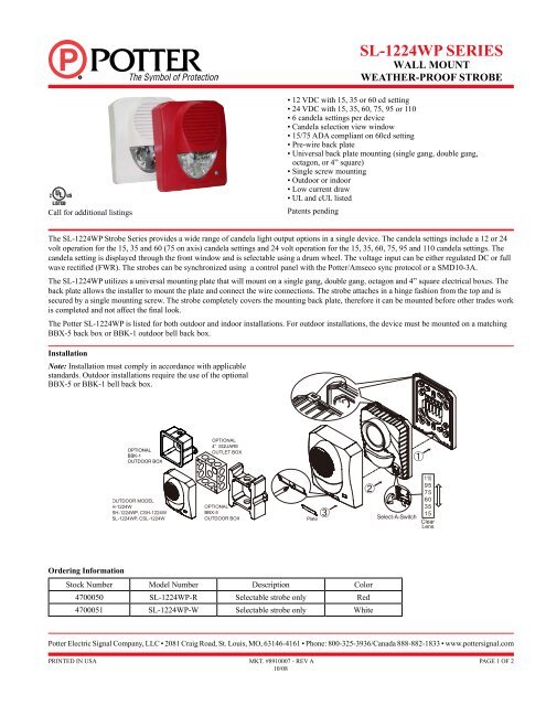
OPTIONAL<br />
BBK-1<br />
OUTDOOR BOX<br />
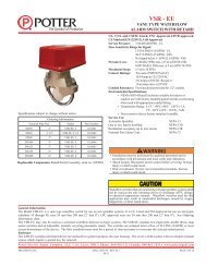
<strong>SL</strong>-<strong>1224WP</strong> <strong>SERIES</strong><br />
WALL MOUNT<br />
WEATHER-PROOF STROBE<br />
<strong>Potter</strong> <strong>Electric</strong> <strong>Signal</strong> <strong>Company</strong>, <strong>LLC</strong> • 2081 Craig Road, St. Louis, MO, 63146-4161 • Phone: 800-325-3936/Canada 888-882-1833 • www.pottersignal.com<br />
PRINTED IN USA<br />
MKT. #8910007 - REV A<br />
10/08<br />
• 12 VDC with 15, 35 or 60 cd setting<br />
• 24 VDC with 15, 35, 60, 75, 95 or 110<br />
• 6 candela settings per device<br />
• Candela selection view window<br />
• 15/75 ADA compliant on 60cd setting<br />
• Pre-wire back plate<br />
• Universal back plate mounting (single gang, double gang,<br />
octagon, or 4” square)<br />
• Single screw mounting<br />
• Outdoor or indoor<br />
• Low current draw<br />
• UL and cUL listed<br />
Patents pending<br />
The <strong>SL</strong>-<strong>1224WP</strong> Strobe Series provides a wide range of candela light output options in a single device. The candela settings include a 12 or 24<br />
volt operation for the 15, 35 and 60 (75 on axis) candela settings and 24 volt operation for the 15, 35, 60, 75, 95 and 110 candela settings. The<br />
candela setting is displayed through the front window and is selectable using a drum wheel. The voltage input can be either regulated DC or full<br />
wave rectified (FWR). The strobes can be synchronized using a control panel with the <strong>Potter</strong>/Amseco sync protocol or a SMD10-3A.<br />
The <strong>SL</strong>-<strong>1224WP</strong> utilizes a universal mounting plate that will mount on a single gang, double gang, octagon and 4” square electrical boxes. The<br />
back plate allows the installer to mount the plate and connect the wire connections. The strobe attaches in a hinge fashion from the top and is<br />
secured by a single mounting screw. The strobe completely covers the mounting back plate, therefore it can be mounted before other trades work<br />
is completed and not affect the final look.<br />
The <strong>Potter</strong> <strong>SL</strong>-<strong>1224WP</strong> is listed for both outdoor and indoor installations. For outdoor installations, the device must be mounted on a matching<br />
BBX-5 back box or BBK-1 outdoor bell back box.<br />
Installation<br />
Note: Installation must comply in accordance with applicable<br />
standards. Outdoor installations require the use of the optional<br />
BBX-5 or BBK-1 bell back box.<br />
Ordering Information<br />
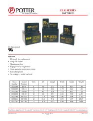
Stock Number Model Number Description Color<br />
4700050 <strong>SL</strong>-<strong>1224WP</strong>-R Selectable strobe only Red<br />
4700051 <strong>SL</strong>-<strong>1224WP</strong>-W Selectable strobe only White<br />
PAGE 1 OF 2
Wiring Diagram Dimensions: inches (mm)<br />
High voltage may be present inside the light assembly even though<br />
power is not connected. If access to the component board is required<br />
(removal or replacement), the capacitor must be discarged by<br />
touching a wire to both ends of the flashtube.<br />
DO NOT attempt to touch or move the assembly until the capacitor<br />
has been discharged.<br />
Specifications<br />
Strobe Current<br />
Light<br />
Output<br />
PRINTED IN USA<br />
Max. RMS Operating Current (mA RMS)<br />
Reg. 12 VDC Reg. 12 FWR Reg. 24 VDC Reg. 24 FWR<br />
15cd 115 151 61 99<br />
35cd 208 265 101 151<br />
60/75cd 253 256 131 189<br />
75cd NA NA 145 207<br />
95cd NA NA 176 242<br />
110cd NA NA 196 267<br />
Note: All current draw shown is worst case.<br />
Voltage 12/24V<br />
UL Designation Regulated 12 DC/FWR Regulated 24 DC/FWR<br />
Operating Voltage Range 8 - 17.5V 16 - 33V<br />
Flash Rate 60 times/min.<br />
Sync Module (SMD10-3A) NA Available<br />
Operating Temperature<br />
Range<br />
DWG# 8910007-1<br />
Indoor model: 32°F to 120°F (0°C to 49°C)<br />
Outdoor model: -40°F to 151°F (-40°C to 66°C)<br />
MKT. #8910007 - REV A<br />
10/08<br />
<strong>SL</strong>-<strong>1224WP</strong> <strong>SERIES</strong><br />
WALL MOUNT<br />
WEATHER-PROOF STROBE<br />
OPTIONAL BBX-5 OUTDOOR BACK BOX<br />
Engineering Specifications<br />
The installer shall provide and install the <strong>Potter</strong> <strong>SL</strong>-<strong>1224WP</strong> selectable strobe. The strobe shall have six (6) candela settings. The candela settings shall<br />
be selectable using a drum roller and shall display the candela setting on the front of the device. The strobe shall operate at 12 or 24 VDC regulated or<br />
full wave rectified (FWR) and shall have an operating range between 8 and 33 VDC. The strobes can be synchronized using a control panel with the<br />
<strong>Potter</strong>/Amseco sync protocol or a SMD10-3A. The strobe shall utilize a mounting plate that allows the installer to pre-wire the mounting plate. The<br />
mounting plate shall be universal and mount on a single gang, double gang, octagon or 4 inch square box. The mounting plate shall be completely<br />
covered by the strobe and shall be secured by a single screw. The <strong>SL</strong>-<strong>1224WP</strong> can be mounted outdoor and is listed for such applications. In outdoor<br />
installations, the <strong>SL</strong>-<strong>1224WP</strong> shall be mounted on either a matching BBX-5 or BBK-1 weatherproof back box. The operating range shall be 32°F to<br />
120°F (0°C to 49°C) for the indoor model and -40°F to 151°F (-40°C to 66°C) for the outdoor model. The strobe shall be UL listed to standard 1638,<br />
General <strong>Signal</strong>ing, and standard 1971, <strong>Signal</strong>ing Devices for the Hearing Impaired. In addition, the strobes shall be cUL listed to CAN-ULC S526.<br />
6 5/64 (154.4)<br />
2 5/16 (59)<br />
5 (127)<br />
3.374 (85.7)<br />
Front View<br />
6.208 (157.7)<br />
3.374 (85.7)<br />
6.515 (165.5)<br />
Bottom View<br />
5.5 (139.7)<br />
0.905<br />
(23)<br />
2 (50.8)<br />
Back View<br />
DWG# 891-1<br />
3.374 (85.7)<br />
Back View<br />
3.374 (85.7)<br />
DWG# 891-2<br />
Light output in percentage when measured from the following<br />
directions per UL1971.<br />
Wall mount vertical dispersion<br />
PAGE 2 OF 2