

10_TRINITY ADVANCED SL instruction manual 01-02a
10_TRINITY ADVANCED SL instruction manual 01-02a
10_TRINITY ADVANCED SL instruction manual 01-02a

Create successful ePaper yourself
Turn your PDF publications into a flip-book with our unique Google optimized e-Paper software.
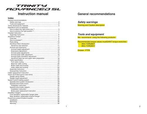
Instruction <strong>manual</strong><br />
Index<br />
General recommendations<br />
Safety warnings ..................................................................................... 2<br />
Tools and equipment ............................................................................. 2<br />
Trinity Advanced <strong>SL</strong> features..................................................................... 3<br />
Operations prior to assembly<br />
How to select the right frame size ? ...................................................... 5<br />
How to acheive the right position ?........................................................ 7<br />
Headset Instruction .................................................................................. . 7<br />
Assembly Instruction............................................................................ . 8<br />
AeroDrive Cockpit .................................................................................... . 9<br />
Overview.............................................................................................. . 9<br />
How to proceed ?................................................................................. . 9<br />
Parts listing .......................................................................................... <strong>10</strong><br />
AeroDrive Stem Introduction ............................................................... 11<br />
AeroDrive size selection ................................................................... 11<br />
Armrest and extensions....................................................................... 13<br />
Armrest height adjustment................................................................ 13<br />
Extensions adjustment...................................................................... 14<br />
Armrest pads adjustments ................................................................ 15<br />
Armrest pads width adjustment ........................................................ 16<br />
Armrest pads orientation adjustment................................................ 17<br />
AeroDrive base bar and upper stem preparation ............................. 18<br />
Cable specification............................................................................... 19<br />
Fork cable routing ............................................................................. 19<br />
Base bar cable routing...................................................................... 20<br />
Brake cable and housing .................................................................. 21<br />
Index cable and housing................................................................... 22<br />
Assembly Instruction............................................................................ 23<br />
Disassembly Instruction....................................................................... 26<br />
Cable replacement <strong>instruction</strong> ................................................................. 26<br />
Vector <strong>SL</strong>R Seat post & seat clamp......................................................... 27<br />
Saddle clamp offsets ........................................................................... 27<br />
Saddle height adjustment .................................................................... 28<br />
Speed Control braking system................................................................. 29<br />
SpeedControl system introduction....................................................... 29<br />
SpeedControl brake levers .................................................................. 29<br />
Installation <strong>instruction</strong>. ...................................................................... 30<br />
SpeedControl brake calipers ............................................................... 31<br />
Installation <strong>instruction</strong>: ...................................................................... 32<br />
Brake pads replacement <strong>instruction</strong>. ................................................ 33<br />
Derailleur hangers.................................................................................... 34<br />
Front derailleur replaceable hanger plate............................................ 34<br />
Rear derailleur replaceable dropout hanger........................................ 34<br />
PowerCore press-fit bottom bracket ........................................................ 35<br />
Installation............................................................................................ 35<br />
Removing............................................................................................. 36<br />
Warranty .............................................................................................. 36<br />
1<br />
General recommendations<br />
Safety warnings<br />
Warning and Caution description<br />
Tools and equipment<br />
We recommend using the following products :<br />
Recommended torque values mustGIANT torque wrenches :<br />
- 4Nm TORQKEY<br />
- 6Nm TORQKEY<br />
Grease : PTFE<br />
2
Trinity Advanced <strong>SL</strong> features<br />
5<br />
3<br />
6<br />
4
Operations prior to assembly<br />
How to select the right frame size ?<br />
The most accurate way to chose from one of the three sizes available is to<br />
refer to the table below.<br />
Please refer to the armrest height to select your frame size.<br />
SADDLE HEIGHT ARMREST HEIGHT<br />
FRAME<br />
SIZE mini max<br />
Low stem<br />
no spacer<br />
High stem<br />
40mm of spacers<br />
(centimeters) (centimeters)<br />
S 65 75 42,9 54,9<br />
M 74 81 45,8 57,8<br />
L 80 89 48,7 60,7<br />
If you are not sure about your armrest height, you can still refer to this basic<br />
size table.<br />
This recommendation helps you to select approximately your frame size<br />
from:<br />
- your height<br />
- your inseam<br />
- your saddle height<br />
- your actual TCR frame size<br />
5<br />
RIDER<br />
SADDLE<br />
SIZE INSEAM HEIGHT<br />
159,3<br />
(centimeters)<br />
73,0 65,0<br />
161,0 74,0 65,9<br />
162,8 75,0 66,8<br />
164,5 76,0 67,6<br />
166,3 77,0 68,5<br />
168,0 78,0 69,4<br />
169,8 79,0 70,3<br />
171,5 80,0 71,2<br />
173,3 81,0 72,1<br />
175,0 82,0 73,0<br />
176,8 83,0 73,9<br />
178,5 84,0 74,8<br />
180,3 85,0 75,7<br />
182,0 86,0 76,5<br />
183,8 87,0 77,4<br />
185,5 88,0 78,3<br />
187,3 89,0 79,2<br />
189,0 90,0 80,1<br />
190,8 91,0 81,0<br />
192,5 92,0 81,9<br />
194,3 93,0 82,8<br />
196,0 94,0 83,7<br />
197,8 95,0 84,6<br />
199,5 96,0 85,4<br />
2<strong>01</strong>,3 97,0 86,3<br />
203,0 98,0 87,2<br />
204,8 99,0 88,1<br />
206,5 <strong>10</strong>0,0 89,0<br />
208,3 <strong>10</strong>1,0 89,9<br />
TCR <strong>TRINITY</strong> ADV <strong>SL</strong><br />
XS/43<br />
S/46,5<br />
M/50<br />
M-L/53,5<br />
L/55,5<br />
XL/58,5<br />
S<br />
M<br />
L<br />
6
How to acheive the right position?<br />
1. Saddle height<br />
The saddle height is basically determined by this calculation:<br />
RIDER INSEAM x 0,89 = SADDLE HEIGHT<br />
2. AeroDrive<br />
A previous bike setup could be adapted to the Trinity Advanced <strong>SL</strong>.<br />
Otherwise, we do recommend starting with the high position stem and<br />
all the highest armrest position.<br />
By setting up the AeroDrive as high as possible, you can progressively<br />
lower the position by changing the stem.<br />
Then, you can fine tune your setup by removing some extension<br />
spacers.<br />
With this procedure, you will save some time and money by avoiding<br />
changing the cables every time you try a new position. -<br />
Once the bar position defined, report to the different parts of this <strong>manual</strong><br />
to assemble your setup.<br />
Headset Instruction<br />
FSA N°26G2 1”1/8<br />
The <strong>TRINITY</strong> Advanced <strong>SL</strong><br />
AeroDrive uses a classic FSA<br />
headset but without the conical cap,<br />
as the stem integrates it’s own top<br />
cap.<br />
Please closely follow the assembly<br />
<strong>instruction</strong>s. Any failure in the<br />
assembly could result in serious<br />
injury or death.<br />
Grease elements as indicated on the<br />
figure.<br />
Figure 1 : FSA N°26G2 headset detail<br />
7<br />
Headset Assembly Instruction<br />
Mounting crown race on fork steerer:<br />
1. Ensure that fork steerer is clean and free of metal chips, dirt and<br />
paint.<br />
2. Apply a thin layer of grease to the crown race seat on the fork<br />
steerer.<br />
3. Tap the crown race on to the steerer using a crown race installation<br />
tool.<br />
Note: Use the correct fitting on the installation tool to ensure no damage is<br />
done to the crown race.<br />
4. Apply a thin layer of grease to bearings, cups, races and<br />
compression rings.<br />
Integrated models only, insert bearings directly into headtube<br />
bearing seat.<br />
5. Slide fork steerer through the headtube.<br />
6. Slide upper bearing race compression ring on to steerer and seat<br />
against upper bearing.<br />
7. Slide upper top cap compression ring on to steerer.<br />
8. Slide top cap on to steerer. Ensure that the integrated cable housing<br />
stop is facing forward.<br />
9. Install any headset spacers and stem.<br />
<strong>10</strong>. Install compression device or star-fangled nut and top cap.<br />
Important: A star-fangled nut should never be installed in a carbon<br />
steerer, use only a compression device such as the FSA<br />
Compressor.<br />
11. Adjust bearing preload by tightening the top screw only until all play<br />
is absent from head assembly and bearings spin freely. Important:<br />
The top screw is for bearing preload only. It is not a fastening screw.<br />
Damage may occur if the top screw is tightened beyond proper<br />
bearing preload.<br />
12. Tighten stem bolts according to the AeroDrive stem assembly<br />
(report to AeroDrive cockpit <strong>instruction</strong>).<br />
8
AeroDrive Cockpit<br />
Overview<br />
AeroDrive is a completely integrated stem, base bar and extension set. None<br />
of the parts included are to be substituted.<br />
The stem is the most critical element. It’s a set consisting of a lower stem<br />
and an upper stem. Three stem sets are provided: low, middle, high.<br />
How to proceed ?<br />
1. Find out your base bar height => select the appropriate AeroDrive<br />
stem<br />
2. fFnd out your armrest height => calculate the spacer height you<br />
need to assemble<br />
3. Assemble the AeroDrive cockpit<br />
Figure 2 : AeroDrive exploded view & designations<br />
Parts listing<br />
Specification Quantity Torque range<br />
[ 1]<br />
armrest<br />
pads<br />
2 -<br />
[2] armrest screws M5x6 tapered 4 4 Nm<br />
[ 3]<br />
armrest<br />
2 -<br />
[ 4]<br />
extension<br />
clamps<br />
2 -<br />
[ 5]<br />
extension<br />
rubber<br />
plugs<br />
2 -<br />
[ 6]<br />
extensions<br />
2 -<br />
[7] tear drop spacers <strong>10</strong>mm 4 -<br />
20mm 2 -<br />
[8] headset compression M6x30 1x For bearing<br />
screw<br />
adjustment.<br />
Report to<br />
headset<br />
<strong>instruction</strong><br />
[9] base bar screws M5x30 2x 6 Nm<br />
M6x35 1x 6 Nm<br />
[ <strong>10</strong>]<br />
upper<br />
stem<br />
3x<br />
low + middle + high<br />
-<br />
[11] steerer screws M5x16 2x 6 Nm<br />
[ 12]<br />
base<br />
bar<br />
1 -<br />
[13] base bar assembly<br />
screw<br />
M4x30 1x 4 Nm<br />
[14] extension clamp M6x75 (40mm)<br />
4x 6 Nm<br />
screws<br />
M6x65 (30mm)<br />
M6x55 (20mm)<br />
M6x45 (<strong>10</strong>mm)<br />
M6x35 (0mm)<br />
[15] lower stem 3x (low +<br />
middle + high)<br />
-<br />
[16] lower stem fork<br />
screws<br />
M5x16 2x 6 Nm<br />
[17] lower stem rubber<br />
plug<br />
1<br />
-<br />
9 <strong>10</strong>
AeroDrive Stem Introduction<br />
AeroDrive size selection<br />
The AeroDrive system is provided with three different stems :<br />
- Low (-40mm)<br />
- Middle (0mm)<br />
- High (+40mm)<br />
With this three stem set, you can adjust your base bar height by +/-40mm. A<br />
total range of 80mm for each frame size is possible.<br />
In addition to this, you can add up to 4mm of teardrop washers to space your<br />
armrest over the base bar.<br />
Similar to the table used to select the appropriate frame size, here is some<br />
additional information to select your stem size.<br />
SADDLE<br />
ARMREST HEIGHT<br />
FRAME HEIGHT LOW STEM MIDDLE STEM HIGH STEM<br />
SIZE mini max min max min max min max<br />
(centimeters) (centimeters)<br />
S 65 75 42,9 46,9 46,9 50,9 50,9 54,9<br />
M 74 81 45,8 49,8 49,8 53,8 53,8 57,8<br />
L 80 89 48,7 52,7 52,7 56,7 56,7 60,7<br />
11<br />
Figure 3 : AeroDrive stem range<br />
12
Armrest and extensions<br />
Armrest height adjustment<br />
The armrest supports<br />
height can be<br />
adjusted up to 40mm<br />
with the teardrop<br />
spacers.<br />
Depending on the<br />
selected height, make<br />
sure you are using the<br />
correct screw length<br />
as detailed.<br />
Figure 4 : Armrest height spacers and screws<br />
lengths<br />
13<br />
Extensions adjustment<br />
First, by swapping the extension clamps, you can choose either a wide<br />
extension setup or a narrow setup.<br />
Secondly, you can refine your extension setup by turning the extension’s<br />
bend inward or outward.<br />
As well, the extensions can slide in the clamps. You can adjust the<br />
extensions both fore and aft.<br />
Figure 5 : extensions width adjustment<br />
14
Armrest pads adjustments<br />
Armrest pads fore and aft adjustment.<br />
The armrest pads can be bolted onto the clamps in 2 positions.<br />
Figure 6 : Armrest pads fore and aft adjustment<br />
15<br />
Armrest pads width adjustment<br />
Figure 7 : Armrest pads width adjustment<br />
16
Armrest pads orientation adjustment<br />
Figure 8 : Armrest pads orientation adjustment<br />
AeroDrive base bar and upper stem preparation<br />
The upper stem is designed with a small thread on its inside. This allows you<br />
to steady the base bar during the assembly.<br />
Tighten this bolt to 4 Nm<br />
As soon as you have chosen your stem size, assemble the upper stem with<br />
the base bar as shown bellow.<br />
Figure 9 : Base bar and upper stem preparation<br />
17 18
Cable specification<br />
The cable routing of Trinity Advanced <strong>SL</strong> is one of the most innovative. To<br />
insure optimized performance, make sure to follow the following <strong>instruction</strong>s.<br />
Fork cable routing<br />
To get the smoother cable routing and make sure to get the lower cable<br />
friction, please use the cable routing as shown bellow.<br />
Figure <strong>10</strong> : fork cable routing<br />
Base bar cable routing<br />
To get the smoother cable routing and make sure to get the lower cable<br />
friction, please use the cable routing as shown bellow.<br />
For a traditional cable routing, front brake is mounted on the left, rear brake<br />
on the right.<br />
For United Kingdom or Australia, front brake is mounted on the right, rear<br />
brake on the left.<br />
Figure 11 : base bar cable routing<br />
19 20
Brake cable and housing<br />
Brake cable and hosing quality is important to insure a correct braking<br />
performance.<br />
Giant recommends SHIMANO or JAGWIRE CEX.<br />
As shown on the figure above, a hosing connector is necessary to facilitate<br />
maintenance and the AeroDrive cockpit disassembly.<br />
For a traditional cable routing, front brake is mounted on the left, rear brake<br />
on the right.<br />
For United Kingdom or Australia, front brake is mounted on the right, rear<br />
brake on the left.<br />
Figure 12 : brake cable routing<br />
21<br />
Index cable and housing<br />
Giant strongly recommends the following cable routing and following cable<br />
and hosing specification.<br />
NOKON Konkavex hosing and liner is necessary in certain area of the<br />
frameset.<br />
More info on NOKON products : http://www.nokon.de<br />
For “Classic” hosing, SHIMANO SIS-SP41 or JAGWIRE LEX quality is<br />
required as it’s assembled on our <strong>TRINITY</strong> Advanced <strong>SL</strong> complete bikes.<br />
Figure 13: index cable routing<br />
22
Assembly Instruction<br />
The Giant Trinity Advanced <strong>SL</strong> is using a traditional headset steering<br />
combined with AeroDrive cockpit components.<br />
Please closely follow the assembly <strong>instruction</strong>s. Any failure in the assembly<br />
could result in serious injury or death.<br />
Caution<br />
You need to have first proceeded to the part “AeroDrive size selection“<br />
before starting executing this <strong>instruction</strong>.<br />
Cable routing and cable length may be compromised if you have not<br />
determined correctly your appropriate settings.<br />
Warning<br />
Grease all thread and screw before assembly.<br />
Do not grease the stem and base bar contact area.<br />
Do not grease the extensions and extension clamps contact areas.<br />
1 Assemble the headset bearings, cups and cones as detailed at Headset<br />
Instruction<br />
2 Fix the base bar to the “upper stem<br />
[<strong>10</strong>]” with the “base bar assembly<br />
screw [13]”. Tighten this bolt to 4 Nm<br />
CAUTION:<br />
this bolt is not designed to clamp<br />
firmly the base bar. Do not apply any<br />
force to the base bar.<br />
23<br />
3 Assemble the extension set to the<br />
“base bar [12]” as detailed at Armrest<br />
and extensions<br />
Armrest includes :<br />
- extension clamps [4]<br />
- extension rubber plugs [5]<br />
- extensions [6]<br />
- tear drop spacers (depending<br />
your necessary adjustment) [7]<br />
- extension clamp screws [14]<br />
Tighten the extension clamp<br />
screws [14] to 6Nm<br />
4 Assemble the cables by routing them<br />
into the “base bar [12]” as detailed at<br />
Base bar cable routing<br />
- assemble the brake cables<br />
first with the brake levers<br />
- assemble the index cables<br />
with the shifters (either for<br />
mechanical systems or<br />
SHIMANO DI²)<br />
5 Install the all cockpit set to the fork<br />
steerer tube. Tighten slightly the<br />
headset compression screw[8] in<br />
addition to the steerer screws to<br />
maintain the stem in a stable position.<br />
Do not tighten the screws to the<br />
recommended torque value yet.<br />
6 Install front and rear brakes as well<br />
as derailleurs<br />
7 Route the cables through the fork<br />
crown as detailed at Fork cable<br />
routing<br />
24
8 Adjust the cable length by cutting the housing at the appropriate length.<br />
The cockpit cable must connect the frame cable just after the front brake.<br />
CAUTION:<br />
Your cockpit setup must be finalized before adjusting and connecting the<br />
cables.<br />
9 Connect the cockpit cables with the frame cables and setup your brakes and<br />
derailleurs.<br />
CAUTION:<br />
Make sure the cable routing is smooth and that cable are sliding in<br />
housing with a minimal friction.<br />
The cables should not interfere with the headtube significantly: the<br />
cables should flex and return free into the frame cable entrance.<br />
<strong>10</strong> Attach the lower stem [15] to the fork<br />
with the 2 lower stem fork screws<br />
[16].<br />
CAUTION:<br />
Do not tighten the screws to the<br />
recommended torque value yet.<br />
11 Attach the lower stem [15] to the<br />
upper stem [<strong>10</strong>] with the 3 screws<br />
base bar screws [9].<br />
CAUTION:<br />
Do not tighten the screws to the<br />
recommended torque value yet.<br />
12 With the lower stem [15] attached but loose, compress the headset with the<br />
headset compression screw [8].<br />
Adjust bearing preload by tightening the headset compression screw [8] only<br />
until all play is absent from head assembly and bearings spin freely.<br />
CAUTION:<br />
The top screw is for bearing preload only. It is not a fastening screw.<br />
Damage may occur if the top screw is tightened beyond proper bearing<br />
preload.<br />
13 Clamp the upper stem [<strong>10</strong>] to the fork steerer tube by tightening the steerer<br />
screws [11] to 6Nm<br />
14 Clamp the lower stem [15] to the upper stem [<strong>10</strong>] with the 3 screws base bar<br />
screws [9] by tightening” to 6Nm<br />
15 Clamp the lower stem [15] to the fork with the 2 lower stem fork screws [16] by<br />
tightening to 6Nm<br />
16 Plug the rubber cap lower stem rubber plug [17] by pressing it in place<br />
25<br />
Disassembly Instruction<br />
1. Unplug the rubber cap lower stem rubber plug [17]<br />
2. Unscrew the “lower stem [15]” to the fork with the 2 lower stem fork<br />
screws [16]<br />
3. Unscrew the “lower stem [15]” to the upper stem [<strong>10</strong>] with the 3<br />
screws base bar screws [9]<br />
4. Remove the lower stem [15]<br />
5. Detach the cables and remove them from the fork crown (if<br />
necessary)<br />
Make sure you are securing the frame cables while removing the<br />
inner cables.<br />
6. Unscrew the base bar assembly screw [13] and take off the base bar<br />
from the upper stem [<strong>10</strong>]<br />
7. Remove the cables from the base bar [12] (if necessary)<br />
- disassemble the brake cables first with the brake levers<br />
- disassemble the index cables with the shifters (either for<br />
mechanical systems or SHIMANO DI²)<br />
8. Disassemble the extensions and armrest from the base bar<br />
9. Unscrew the steerer screws [11] and remove the upper stem [<strong>10</strong>]<br />
from the fork steerer<br />
<strong>10</strong>. Disassemble the headset bearings, cups and cones<br />
Cable replacement <strong>instruction</strong><br />
1. Detach the cable from the derailleur or brake and pull only the inner<br />
cable out.<br />
Make sure you are securing the frame cables while removing the<br />
inner cables.<br />
2. Insert a new cable from the shifter or brake lever until it shows up at<br />
the connector behind the fork. Pull the inner cable all the way out.<br />
3. For derailleurs or rear brake, pull the Nokon housing carefully straight<br />
Make sure that the both housing end will not move and be pulled<br />
inside the frame<br />
4. Insert the inner cable into the Nokon or cable housing carefully until it<br />
shows up at the other end<br />
5. Pull the inner cables firmly to compress the all cable routing<br />
assembly.<br />
Make sure that every ferrule and cable are in place.<br />
6. Attach the cable to derailleur or brake following their respective<br />
<strong>instruction</strong>.<br />
26
Vector <strong>SL</strong>R Seat post & seat clamp<br />
The seatpost design is one of the most aerodynamic and light weight designs<br />
available.<br />
Saddle clamp offsets<br />
The Vector <strong>SL</strong> seat post provides 3 offset choices: -20, 0, +20mm.<br />
Figure 14 : Vector <strong>SL</strong>R saddle clamp offsets<br />
For reference, the table bellow indicates the various effective seat angles at<br />
the reference saddle heights:<br />
Frame size S M L<br />
E D1 E D1 E D1<br />
Reference<br />
saddle height<br />
69 cm 77 cm 85 cm<br />
P1 (-20mm) 77,535° 502,25 77,495° 524,02 78,535° 534,79<br />
P2 (0mm) 75,644° 519,26 75,823° 539,29 77,009° 549,82<br />
P3 (+20mm) 73,733° 536,33 74,131° 555,60 75,467° 565,21<br />
In addition to the Vector <strong>SL</strong>R seat post offset adjustments, your saddle rail<br />
can slide to acheive your exact saddle position<br />
27<br />
Vector <strong>SL</strong>R height adjustment<br />
WARNING To avoid serious injury<br />
Vector <strong>SL</strong>R seat post is designed to be cut at the appropriate length to<br />
match your saddle height.<br />
Cutting Vector <strong>SL</strong>R seat post requires extreme caution.<br />
For any questions regarding methods of installation, adjustment,<br />
maintenance or operation, please<br />
contact your Giant dealer.<br />
CAUTION<br />
Make sure you have anticipated the saddle offset adjustment as it will<br />
influence the saddle height.<br />
The seatpost holder is not a traditional seatpost clamp. Pay attention to<br />
the recommended torque of 2Nm.<br />
Over-tightening the seatpost may result in damaging the frame and the<br />
seatpost.<br />
Vector <strong>SL</strong>R must be cut at the appropriate length and needs to be to be<br />
supported by the frame inner stopper.<br />
Once cut, your saddle height can still be increased and be adjusted with the<br />
Vector <strong>SL</strong>R spacers.<br />
Figure 15 : Vector <strong>SL</strong>R height adjustment<br />
The rubber seal is necessary to protect dust and projections to get into the<br />
clamp mechanism or into the frames tubes.<br />
The rubber is not waterproof and will not fully protect against water spray<br />
getting into the frame. Make sure to periodically check seatpost, clamp parts<br />
and seattube.<br />
28
Speed Control braking system<br />
SpeedControl system introduction<br />
SpeedControl is specifically designed for the Trinity Advanced <strong>SL</strong>. It is<br />
impossible to substitute another brake system.<br />
WARNING To avoid serious injury<br />
Improper use of your bicycle's brake system may result in a loss of<br />
control or an accident, which could lead to a severe injury. Because<br />
each bicycle may handle differently, be sure to learn the proper braking<br />
technique (including brake lever pressure and bicycle control<br />
characteristics) with your Trinity Advanced <strong>SL</strong>.<br />
Consult your bicycle dealer and practice your riding and braking<br />
technique as necessary.<br />
SpeedControl brake levers<br />
WARNING To avoid serious injury<br />
• You must never modify the levers, otherwise the lever may break and<br />
the brakes may no longer work as a result.<br />
• Before riding the bicycle, check that there is no damage such as crack<br />
or bent. If there is any damage, replace with a new part immediately<br />
without trying to repair the damage, otherwise the lever may break and<br />
the brakes may no longer work as a result.<br />
• Obtain and read the service <strong>instruction</strong>s carefully prior to installing the<br />
parts.<br />
Loose, worn or damaged parts may cause the bicycle to fall over and<br />
serious injury may occur as a result.<br />
• Read these Technical Service Instructions carefully, and keep them in<br />
a safe place for later reference.<br />
29<br />
Installation <strong>instruction</strong>:<br />
Pass the outer casing through the handlebar, and then adjust its length<br />
so that it will fit securely into the outer casing holder when the brake<br />
lever is installed.<br />
Report to Base bar cable routing for additional routing <strong>instruction</strong>.<br />
Be sure to leave some excess cable, even if cutting it to the full length of<br />
the handlebars.<br />
1. Install the brake lever to the handlebar by using a 5 mm Allen key to<br />
turn it counterclockwise as shown in the illustration.<br />
Tightening torque: 6 Nm<br />
2. Install the inner cable. Make sure that the inner end is firmly seated in<br />
the cable hook.<br />
30
SpeedControl brake calipers<br />
WARNING To avoid serious injury<br />
Securely tighten the caliper brake mounting nuts to the specified<br />
tightening torque.<br />
Only use the nuts provided with the SpeedControl brake calipers. Do<br />
not use any other nut type.<br />
If the nuts become loose and the brakes fall off, they may get caught up<br />
in the bicycle and result in a crash.<br />
Particularly if this happens with the front wheel, the bicycle may be<br />
thrown forward and serious injury could result.<br />
Front brake is designed for use as front brake only and rear brake is<br />
designed for use as rear brake only. Reversing the brakes main result in<br />
poor braking performance and serious injury in case or malfunction.<br />
Obtain and read the service <strong>instruction</strong>s carefully prior to installing the<br />
parts.<br />
Loose, worn, or damaged parts may cause serious injury to the rider.<br />
We strongly recommend only using genuine GIANT replacement parts.<br />
Be careful not to allow any oil or grease to get onto the brake pads. If<br />
any oil or grease does get on the pads, you should replace the pads,<br />
otherwise the brakes may not work correctly.<br />
Control regularly the rim braking surface as braking safety and<br />
performance may be affected. Be careful not to allow any oil or grease<br />
onto the rim braking surface. Check and clean the rims frequently<br />
respecting the rim manufacturer recommendations.<br />
Check the brake cable for rust and fraying and replace the cable<br />
immediately if any such problems are found. If this is not done, the<br />
brakes may not work correctly.<br />
Always make sure that the front and rear brakes are working correctly<br />
before you ride the bicycle.<br />
The required braking distance will be longer during wet weather.<br />
Reduce your speed and apply the brakes early and gently.<br />
If the road surface is wet, the tires will skid more easily. If the tires skid,<br />
you may fall off the bicycle. To avoid this, reduce your speed and apply<br />
the brakes early and gently.<br />
Read these Technical Service Instructions carefully, and keep them in a<br />
safe place for later reference.<br />
31<br />
Installation <strong>instruction</strong>:<br />
1. Install the brake caliper to the front fork or to the frame with the<br />
specific nut.<br />
Tightening torque: 8 – <strong>10</strong> Nm<br />
2. Brake pads alignment<br />
After adjusting the brake pads so that the pad surface and the rim<br />
surface are as shown in the illustration, tighten the shoe fixing bolt.<br />
Tightening torque: 5 – 7 Nm<br />
3. Inner cable attachment<br />
Adjust the pads clearance (as shown in the illustration below) and<br />
secure the cable.<br />
Use the barrel to adjust the shoes clearance and get the appropriate<br />
brake feel.<br />
Tightening torque: 6 – 8 Nm<br />
32
Brake pads replacement <strong>instruction</strong>:<br />
WARNING To avoid serious injury<br />
Brake pads are subject to wear. Before riding the bicycle, check that the<br />
pads wear indicator is still visible (grooves). If the brake pads have<br />
worn down until the grooves are no longer visible, they should be<br />
replaced.<br />
SpeedControl brake pad cartridges are designed following Shimano<br />
standards.<br />
In order to insure the best braking efficiency and to avoid rim damage,<br />
please refer to the rim or wheel <strong>instruction</strong> <strong>manual</strong>. Carbon or aluminum<br />
rims require different pad quality. Make sure you have assembled the<br />
correct pads correctly.<br />
There are two different types of pad and pad holder to be used in the left and<br />
right positions respectively. Slide the new pads into the grooves on the pad<br />
holders while taking note of the correct directions and bolt hole positions.<br />
Tightening torque: 1,5 Nm<br />
Derailleur hangers<br />
WARNING To avoid serious injury<br />
Front and rear derailleur hangers are removable in order to let you<br />
replace them after damage.<br />
• You must never modify the hangers, otherwise the derailleurs mount<br />
may be unsecured and result in poor shifting performance. If the hanger<br />
or derailleur becomes loose, the parts may fall off and may get caught<br />
up into the rear wheel, causing a crash.<br />
• Before riding the bicycle, check that there is no damage such as crack<br />
or bent. If there is any damage, replace the hanger with a genuine<br />
GIANT hanger.<br />
Front derailleur replaceable hanger plate<br />
The front derailleur hanger is assembled with 2 screws.<br />
Thread compound is recommended to avoid the screws to get loose.<br />
Tightening torque: 4 Nm<br />
Rear derailleur replaceable dropout hanger<br />
The rear derailleur hanger is assembled with 2 screws.<br />
Thread compound is recommended to avoid the screws to get loose.<br />
Tightening torque: 4 Nm<br />
33 34
PowerCore press-fit bottom bracket<br />
WARNING<br />
Do not modify the frame. Do not face, grind or cut the bottom bracket<br />
shell. Any modification will affect the bottom bracket interface and will<br />
void the warranty.<br />
Failure to follow these <strong>instruction</strong>s may result in hidden damage to the<br />
composite frameset. Damage to the frameset may cause loss of structural<br />
integrity, which may result in serious personal injury.<br />
Only proper installation will bring out the best performance and comfort in<br />
your frameset. Since the installation of the Press-Fit BB adapter is a<br />
complicated task requiring training and experience, only Giant authorized<br />
dealers should complete the sophisticated process.<br />
There are different types of Press-Fit BB adapters. Be sure to check the table<br />
below before selecting which BB adapter to use. If the BB adapter is not<br />
suitable, serious personal injury may result.<br />
BB Adapter Model Chainwheel/Crank Model<br />
SHIMANO ISMC7800P SHIMANO HollowTech II<br />
FSA<br />
BB-AL86<br />
Installation<br />
Step 1:<br />
1. Apply neutral grease inside the<br />
frame’s bottom bracket cups<br />
2. Then install the left and righthand<br />
press-fit BB adapters<br />
3. Press-fit the adapters by<br />
tightening them in a vise, while<br />
applying pressure evenly to both<br />
sides so that they do not become<br />
angled<br />
CAUTION<br />
When doing this, push only at the points<br />
indicated by arrows in the illustration.<br />
Pushing anywhere other than these<br />
points may damage the ball races of the<br />
bearings.<br />
FSA<br />
MEGAEXO<br />
Alloy<br />
Series<br />
FSA BB90-CF86 Ceramic FSA MEGAEXO Carbon Series<br />
FSA<br />
BB90-CF86<br />
SRAM<br />
BB<br />
FSA<br />
MEGAEXO<br />
Carbon<br />
Series<br />
SRAM<br />
GXP<br />
Series<br />
CAMPAGNOLO IC9-RE41 ULTRA TORQUE SERIES<br />
35<br />
Step 2:<br />
Installation of the front chainwheel/crank:<br />
NOTE: Make sure to follow the<br />
installation <strong>instruction</strong>s provided by the<br />
manufacturers of the chainwheel/crank.<br />
NOTE: This <strong>manual</strong> is designed to<br />
provide information for installation of a<br />
bottom bracket into a Giant composite<br />
frameset. Please refer to the specific<br />
manufacturers’ enclosed guide for final<br />
crankset installation details.<br />
Removing<br />
Push out firmly from the inside using a blunt tool.<br />
NOTICE: Do not reuse the adapters as they can be damaged from removal.<br />
CAUTION<br />
Avoid scratching or damaging the frame/BB shell during the removal of the<br />
BB adapters<br />
Warranty<br />
Please refer to the Giant Owner’s Manual or visit our Web site: www.giantbicycles.com<br />
for complete provisions of the warranty.<br />
36