e-Pro Live Assembly Manual - Pearl Music Europe
e-Pro Live Assembly Manual - Pearl Music Europe
e-Pro Live Assembly Manual - Pearl Music Europe

You also want an ePaper? Increase the reach of your titles
YUMPU automatically turns print PDFs into web optimized ePapers that Google loves.
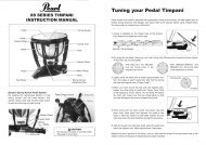
http://www.pearldrum.com<br />
<strong>Pro</strong>ducts and specifications are subject to change without notice.<br />
Printed in Taiwan<br />
-1003-<br />
sample<br />
PEARL<br />
Instruction <strong>Manual</strong><br />
Congratulations on your purchase! To get optimum performance of your E-PRO <strong>Live</strong> Drums,<br />
please read this Instruction <strong>Manual</strong> before playing.
SET-UP EXAMPLE (FRONT) SET-UP EXAMPLE (BACK)<br />
P<br />
N<br />
O<br />
A Bass Drum<br />
B Snare Stand<br />
C Hi-Hat Controller<br />
D Drum Rack<br />
E Hi-Hat Holder<br />
F Cable Harness<br />
A<br />
M<br />
L<br />
K<br />
G r.e.d.box Module<br />
H 12” Hi-Hat Cymbal<br />
I 13” Crash Cymbal<br />
J Snare Drum<br />
K Cymbal Holder<br />
J<br />
B<br />
I<br />
H<br />
L 10” Tom Tom<br />
M 12” Tom Tom<br />
N 16” Ride Cymbal<br />
O Velcro Strap<br />
P 14” Tom Tom<br />
G F<br />
D<br />
sample<br />
E<br />
C C<br />
Q Drum Pedal (Optional)<br />
R Tru-Trac Bass Drumhead<br />
S 14” Tru-Trac Drumhead<br />
T 12” Tru-Trac Drumhead<br />
U 10” Tru-Trac Drumhead<br />
V 14” Tru-Trac Drumhead<br />
W 12” Rubber Hi-Hat Cymbal<br />
X 12” Rubber Crash Cymbal<br />
Y 14” Rubber Ride Cymbal<br />
- 1 - - 2 -<br />
F<br />
G<br />
W X Y<br />
E<br />
H<br />
I N<br />
V<br />
B<br />
U T<br />
Q<br />
R<br />
S<br />
D
COMPONENTS / HARDWARE CARTON COMPONENTS / DRUM CARTON<br />
H-1 D-1 D-2 D-3 D-4<br />
H-2<br />
H-5<br />
H-3<br />
H-6<br />
H-1 Drum Rack (x1) Includes : PC-8 Pipe Clamps (4)<br />
H-2 S-790 (x1) Snare Stand<br />
H-3 CH-80E (x2) Cymbal Holders<br />
H-7<br />
H-4<br />
H-4 CLH-80E (x1) Hi-Hat Holder<br />
H-5 UX-80 (x1) Universal Clamp<br />
H-6 TH-900S (x3) Tom Holders<br />
H-7 NP-485 (x12) Velcro Straps<br />
sample<br />
D-5 D-6<br />
- 3 - - 4 -<br />
D-9<br />
D-10<br />
D-8<br />
D-12 D-13 D-14<br />
D-1 EDD1445S (x1) 14"x 4.5" SD<br />
D-2 EDD1065T (x1) 10"x 6.5" TT<br />
D-3 EDD1207T (x1) 12"x 7" TT<br />
D-4 EDD1408T (x1) 14"x 8" TT<br />
D-5 EDD2012B (x1) 20"x 12"BD<br />
D-6 EBC-20F (x1) BD Front Side Head<br />
D-7 EBC-20EB (x1) BD Batter Side Head<br />
D-8 RIM-20RB (x2) BD Hoop<br />
D-11<br />
D-7<br />
D-9 NP-1 (x1) Rubber Hoop <strong>Pro</strong>tector<br />
D-10 CW-80 / T-066X (x16) BD Claws, BD Tension Rods,<br />
W7/32 x 110mm<br />
D-11 NP-488L (x1) BD Cushion<br />
D-12 CH-1JB (x5) Jack Box Cable<br />
D-13 K-050 (x1) Drum Key<br />
D-14 Hex Wrench (x1) (5mm)
COMPONENTS / ELECTRONICS CARTON COMPONENTS / BRASS CYMBAL CARTON<br />
E-1 E-2 E-3<br />
B-1<br />
E-4<br />
E-7 E-8<br />
E-1 TTP-14 (x2) 14” Tru-Trac Drumheads<br />
E-2 TTP-10 (x1) 10” Tru-Trac Drumhead<br />
E-3 TTP-12 (x1) 12” Tru-Trac Drumhead<br />
E-4 TTP-B (x1) Tru-Trac Bass Drumhead<br />
E-5 E-6<br />
E-5 EHH-1 (x1) HH Controller<br />
E-6 CH-10 (x1) Cable Harness<br />
E-7 RDM-20M/M (x1) r.e.d.box Module & Mounting Bracket<br />
E-8 Power Supply (x1)<br />
- 5 - - 6 -<br />
B-5<br />
sample<br />
B-1 ECC-12S (x1) 12” Brass HH Cymbal<br />
B-2 ECC-12B (x1) 12” Plastic Bottom HH<br />
B-3 ECC-13D (x1) 13” Brass Crash Cymbal<br />
B-4 ECC-16T (x1) 16” Brass Ride Cymbal<br />
B-5 CM-1 (x2) Cymbal Mount<br />
B-2 B-3 B-4<br />
COMPONENT / RUBBER CYMBAL CARTON<br />
P-1 P-2 P-3 P-4<br />
P-1 EPC-12S (x1) 12” Rubber HH Cymbal<br />
P-2 EPC-12D (x1) 12” Rubber Crash Cymbal<br />
P-3 EPC-14T (x1) 14” Rubber Ride Cymbal<br />
P-4 CM-1 (x2) Cymbal Mount
SETTING UP THE RACK<br />
1. Locate the two “long” legs (each has a PCL-100 Pipe<br />
Bracket attached) and connect one to each end of the<br />
Front Bar (it has a <strong>Pearl</strong> logo badge) as shown (Fig. 1).<br />
Orient the Front Bar so that the “<strong>Pearl</strong>” logo on the<br />
clamps is facing right-side up for optimum stability<br />
(Fig. 1-A).<br />
2. Connect a Side Bar to the left “long” leg as shown (Fig.<br />
2) with the “<strong>Pearl</strong>” logo on the clamps facing right-side<br />
up for optimum stability (Fig.1-A). Locate the “short”<br />
leg with a PCL-100 Pipe Bracket attached and connect<br />
it to the other end of the Side Bar as shown.<br />
3. Connect the last Side Bar to the right “long” leg as<br />
shown (Fig. 3) with the “<strong>Pearl</strong>” logo on the clamps<br />
facing right-side up for optimum stability (Fig. 1-A).<br />
Connect the remaining “short” leg to the other end of<br />
the Side Bar as shown.<br />
4. Adjust the height of the Front and Side Bars to your<br />
preference and make sure that all bars are levelled.<br />
5. Attach two Pipe Clamps to the Front Bar and one each<br />
on both Side Bars (Fig. 4 and 4-A).<br />
6. Attach the Tom Holders, Cymbal Holders, Hi-Hat<br />
Holder and the Universal Clamp to the Pipe Clamps<br />
and Pipe Bracket as shown below (Fig. 5).<br />
7. Reverse the position of the left and right Side Bars if<br />
you’re left-handed.<br />
Caution<br />
*Remove all components from the Pipe Clamps and Pipe<br />
Brackets before making adjustments to the height of the<br />
rackor position of the Pipe Clamps.<br />
*Securely tighten (don’t over-tighten) all handle bolts on the<br />
Pipe Clamps and Pipe Brackets when the positions are<br />
finalized.<br />
Fig.4-A<br />
Fig.4<br />
Cymbal Holder<br />
PCL-100 Pipe Bracket<br />
Fig.1-A<br />
Cymbal Holder<br />
Tom Holders<br />
Bar<br />
Long Leg<br />
PCL-100<br />
Pipe Bracket<br />
Short Leg<br />
Hi-Hat Holder<br />
Fig.1<br />
Fig.2<br />
Fig.3<br />
sample<br />
Universal<br />
Clamp<br />
Fig.5<br />
ASSEMBLYING THE TOMS AND SNARE DRUM<br />
Note<br />
*The bottom head on the Toms and the snare side head on<br />
the Snare Drum are pre-assembled at the factory.<br />
1. Loosen the Tension Bolts on the batter side of the<br />
drums using the provided Drum Key and remove the<br />
Hoops (Fig. 6).<br />
2. Locate the Tru-trac Drumhead that corresponds to the<br />
diameter of each drum. NOTE: The two 14” Tru-trac<br />
Drumhead are identical and either can be used on the<br />
14” Tom or the Snare Drum.<br />
3. Insert the “L” shaped end of the Jack Box Cable into<br />
the Jack on the underside of the Tru-trac Drumhead<br />
(Fig. 7).<br />
4. Insert the other end of the Jack Box Cable into the<br />
Jack Box inside the shell (Fig. 7).<br />
5. Place the Tru-Trac Drumhead on the shell and reattach<br />
the Hoop with the Tension Bolts (Fig. 8). NOTE: The<br />
Jack Box Cables are short and have only limited reach.<br />
When assembling Toms, align the Tru-Trac logo with<br />
the BT-70 Tom Holder Bracket as shown (Fig. 8-A).<br />
Similarly, when assembling the Snare Drum, align the<br />
Tru-Trac logo with the E-<strong>Pro</strong> <strong>Live</strong> Badge.<br />
Caution<br />
*Tighten the Tension Bolts with only enough tension to hold<br />
the Hoop in place. Using greater tension can damage the<br />
plastic frame of the Tru-trac Drumheads and void the<br />
warranty.<br />
- 7 - - 8 -<br />
Lug<br />
BT-70<br />
Fig.8-A<br />
Jack Box<br />
Cable<br />
Tesion Bolt<br />
Hoop<br />
Lug<br />
Fig.6<br />
Tru-trac Drumhead<br />
Jack Box<br />
Tension Bolt<br />
Hoop<br />
Fig.7<br />
Tru-trac Drumhead<br />
Lug<br />
BT-70<br />
Fig.8
ASSEMBLYING THE TRU-TRAC BASS DRUMHEAD<br />
1. Unscrew the bolts on the Tru-Trac Bass Drumhead<br />
using the provided Hex wrench and remove the black<br />
steel hoop (Fig. 9).<br />
2. Turn the Tru-Trac Bass Drumhead over and place it on<br />
your hand (Fig. 10).<br />
3. Place the Bass Drum Head over the Tru-Trac Bass<br />
Drumhead as shown making sure that the Guide Posts<br />
on the Tru-Trac Bass Drumhead are inserted into the<br />
corresponding guide holes in the Bass Drum Head<br />
(Fig. 10-A & 10-B).<br />
4. Place the black steel hoop as shown making sure that<br />
the Guide Posts on the Tru-Trac Bass Drumhead are<br />
inserted into the corresponding guide holes in the<br />
black steel hoop (Fig. 10 & 10-B).<br />
5. Hand tighten the bolts on the Tru-Trac Bass Drumhead<br />
from underneath.<br />
6. Turn the Bass Drum Head over and tighten the bolts<br />
securely using the provided Hex wrench.<br />
Note<br />
*The Bass Drum Head will be floppy at this point but will<br />
become taut when attached to the shell and tightened.<br />
Fig.10-A<br />
Guide<br />
Post<br />
Guide Post<br />
Top<br />
Bottom<br />
Washer<br />
Bolt<br />
Bolt<br />
Washer<br />
Tru-Trac<br />
Bass Drumhead<br />
Black Steel<br />
Hoop<br />
Black Steel<br />
Hoop<br />
Fig.9<br />
Tru-Trac<br />
Bass Drumhead<br />
Black Steel<br />
Hoop<br />
Guide Post<br />
Fig.10<br />
sample<br />
Tru-Trac<br />
Bass Drumhead<br />
Bass Drum Head<br />
Fig.10-B<br />
ASSEMBLYING THE BASS DRUM<br />
1. Place the Front Head on to the Bass Drum shell as<br />
shown with the <strong>Pearl</strong> logo up and square the <strong>Pearl</strong> logo<br />
(Fig. 11). Place the Bass Drum hoop over the head with<br />
the flat side of the hoop facing down (Fig. 11-A). Hook<br />
a Tension Rod and Claw on the Hoop above each lug<br />
and tighten the Tension Rods using the provided Drum<br />
Key.<br />
2. Turn the drum over and put the Bass Drum Cushion<br />
inside and at the bottom the Bass Drum Shell. Make<br />
sure that the Cushion doesn't touch the Jack Box<br />
inside the shell<br />
(Fig. 12).<br />
3. Insert the “L” shaped end of the Jack Box Cable into<br />
the Tru-Trac Bass Drumhead as shown (Fig. 13-A) and<br />
insert the other end of the cable into the Jack Box<br />
inside the Bass Drum shell as shown (Fig. 13-A).<br />
4. Place the Batter Side Head onto the Bass Drum shell<br />
with the Tru-Trac Bass Drumhead facing the top of the<br />
Bass Drum as shown (Fig. 14). Place the Bass Drum<br />
Hoop over the head with the flat side of the hoop<br />
facing down (Fig. 14-A).<br />
5. Hook a Tension Rod and Claw on the Hoop above<br />
each lug and tighten the Tension Rods using the<br />
provided Drum Key (Fig. 14-A).<br />
6. Attach the Hoop <strong>Pro</strong>tector on the batter side hoop<br />
where you attach your pedal.<br />
Jack Box Cable<br />
Fig.13-A<br />
- 9 - - 10 -<br />
Head<br />
Jack Box<br />
Fig.11-A<br />
Claw<br />
Hoop<br />
Tesion Rod<br />
Claw<br />
Hoop<br />
Bass Drum Cushion<br />
Hoop <strong>Pro</strong>tector<br />
Tesion Bolt<br />
Claw<br />
Fig.14-A<br />
Claw<br />
Hoop<br />
Hoop<br />
Fig.11<br />
Fig.12<br />
Fig.13 Fig.14
SETTING THE DRUMS ON THE RACK<br />
BASS DRUM<br />
Position the Bass Drum upright and set the Bass Drum<br />
Spurs as shown with the front of the drum about an inch<br />
off the floor (Fig. 15).<br />
The Bass Drum Spurs have spike tips (for added slip<br />
resistance) that can be exposed by turning the Lock Nut<br />
and Rubber Tip clockwise (Fig. 15).<br />
Warning<br />
*Use the spikes only on thick carpeted surfaces to prevent<br />
damage to the flooring underneath.<br />
TOM TOM<br />
Make sure that the Tom Holders and the Pipe Clamps are<br />
securely attached. Attach the Toms to the Tom Holders<br />
and position the height and angles to your preference.<br />
When done, set the tab on the StopLock into the slot in<br />
the Pipe Clamp and Tom Holder Bracket and tighten the<br />
Key Bolts with the provided Drum Key to retain the angle<br />
and height settings (Fig. 16).<br />
SNARE STAND/DRUM<br />
Open the legs of the stand to form a stable tripod and<br />
insert the Top Section into the base.<br />
Open the basket and adjust the Butterfly Nut as needed<br />
to accommodate the snare drum.<br />
Place the snare drum into the basket and tighten the<br />
Butterfly Nut to hold the drum securely (do not<br />
overtighten) (Fig. 17).<br />
Caution<br />
*Make sure all bolts and nuts are tighten after setting.<br />
Spike<br />
StopLock<br />
Pipe Clamp<br />
StopLock<br />
Tom Holder<br />
Spur<br />
Lock Nut<br />
Rubber Tip<br />
Fig.15<br />
Tom Holder Bracket<br />
Butterfly Nut<br />
Fig.16<br />
sample<br />
Fig.17<br />
ASSEMBLYING THE r.e.d.box Module<br />
1. Attach the r.e.d.box Mount to the bottom of the<br />
r.e.d.box as shown using a screwdriver. Do not<br />
overtighten (Fig. 18).<br />
2. Insert the Mount into the Universal Clamp and tighten<br />
the Wing Nut (Fig. 19). Note: Keep the jaws of the<br />
clamp parallel.<br />
3. Adjust the height and angle of the r.e.d. box Module to<br />
your preference.<br />
ASSEMBLYING THE CYMBAL HOLDER<br />
1. Unscrew the Wing Nut on the Cymbal Holder and<br />
detach the Felt Washer. Put both aside for now.<br />
2. Attach the Cymbal Mount onto the Cymbal Post and<br />
rotate the Attachment Screw until it's at a right angle to<br />
the Cymbal Holder Tilter as shown (Fig. 20).<br />
3. Tighten the Attachment Screw with the provided Hex<br />
Wrench.<br />
WIRING THE CABLE HARNESS<br />
Note<br />
*The Cable Harness has two sides, one bundled together and the other separated.<br />
1. Each cable is marked with the name of the component it connects to. Take the bundled side and match the cable to<br />
its correcponding jack on the back side of the r.e.d.box (Fig. 21). NOTE: The Ride Cymbal has two Jacks. Make<br />
sure to insert the cables into the correct Jacks<br />
2. Take the separated side and match the cable to its corresponding component.<br />
3. Use the provided Velcro Straps to secure the cables to the rack for a clean look.<br />
- 11 - - 12 -<br />
ON<br />
9V AC<br />
OFF<br />
POWER<br />
7 CRASH 8 RIDE1 9 RIDE2/ACC1 10 ACC2 11 ACC3 12 ACC4<br />
1 KICK<br />
2 SNARE<br />
4 TOM2<br />
4 TOM2<br />
5 TOM3<br />
Mount<br />
Screw<br />
Fig.18<br />
r.e.d.box<br />
Attacment Screw<br />
Cymbal Holder tilter<br />
AUX IN L<br />
6 HI HAT<br />
HH CONTROL MIDI OUT MIDI IN USB AUX IN R<br />
Universal Clamp<br />
1<br />
2<br />
L<br />
R<br />
AUX OUT MAIN OUT<br />
Fig.19<br />
Cymbal Mount<br />
Cymbal Post<br />
Fig.20<br />
Fig.21
WIRING AND MOUNTING CRASH/RIDE CYMBALS<br />
1. Locate the Ride and Crash Cymbal and their matching<br />
cables and insert the cables into the corresponding<br />
jacks. Note: The Ride Cymbal has two Jacks. Make<br />
sure to insert the cables into the correct Jacks<br />
(Fig. 22-A).<br />
2. Attach the Cymbal to the Cymbal Mount and attach the<br />
Felt Washer and Wing Nut in the order shown (Fig. 22).<br />
Make sure that the logo on the Cymbal is facing away<br />
from you to get maximum response from the cymbal.<br />
WIRING AND MOUNTING RUBBER HI-HAT CYMBAL<br />
1. Unscrew the Wing Nut on the Hi-Hat Holder and<br />
remove the Felt and Metal Washers<br />
2. Arrange the Attachment and Support Washer in the<br />
order shown (Fig. 23).<br />
3. Set the Rubber Hi-hat Cymbal on the Support Washer<br />
and Attachment as shown. Note: Make sure that they fit<br />
securely in the recess under the Rubber Hi-hat<br />
Cymbal. Face the logo on the Hi-hat Cymbal away from<br />
you to get maximum response from the cymbal.<br />
4. Reattach the Felt and Metal Washers and the Wing Nut<br />
in the order shown (Fig. 23) and tighten the Wing Nut<br />
to your preference.<br />
5. Connect the Hi-hat cable into the Hi-hat Cymbal Jack.<br />
Note<br />
*The angle of the Hi-Hat Holder can be adjusted with the<br />
gear tilter to your preference.<br />
Fig.22<br />
Support Washer<br />
Attachment<br />
Cymbal Post<br />
Fig.22-A<br />
Wing Nut<br />
Felt Washer<br />
Jack Box<br />
Wing Nut<br />
Metal Washer<br />
Felt Washer<br />
sample<br />
Fig.23<br />
WIRING AND MOUNTING BRASS HI-HAT CYMBAL<br />
1. Unscrew the Wing Nut on the Hi-Hat Holder and<br />
remove the Felt and Metal Washers and the<br />
Attachment.<br />
2. Place the Bottom Plastic Cymbal on the Support<br />
Washer as shown. and reattach the Attachment in the<br />
order shown (Fig. 24).<br />
3. Pass the Hi-hat Cable through the hole in the Bottom<br />
Plastic Cymbal as shown (Fig. 24) and plug it into the<br />
Jack under the Brass Hi-hat Cymbal as shown (Fig.<br />
24-A).<br />
4. Assemble the Brass Hi-hat Cymbal, Felt Washer, Metal<br />
Washer, and Wing Nut in the order shown (Fig. 24).<br />
5. Tighten the Wing Nut to your preference.<br />
Note<br />
*The angle of the Hi-Hat Holder can be adjusted with the<br />
gear tilter to your preference.<br />
- 13 - - 14 -<br />
Fig.24-A<br />
Jack Box Cable<br />
Wing Nut<br />
Metal Washer<br />
Felt Washer<br />
Attachment<br />
Support Washer<br />
Cymbal Post<br />
Fig.24