Technical Details of the Sabre Audio DAC - ESS Technology, Inc.
Technical Details of the Sabre Audio DAC - ESS Technology, Inc.
Technical Details of the Sabre Audio DAC - ESS Technology, Inc.

Create successful ePaper yourself
Turn your PDF publications into a flip-book with our unique Google optimized e-Paper software.
SABRE <strong>DAC</strong> INTERNAL OPERATIONS<br />
Abstract—The <strong>Sabre</strong> <strong>DAC</strong> is an octal audio digital to analog<br />
converter each individual channel <strong>of</strong> which performs with a DNR<br />
<strong>of</strong> >127dB. If used as a Stereo <strong>DAC</strong> <strong>the</strong> performance exceeds<br />
130dB. The THD <strong>of</strong> each <strong>of</strong> <strong>the</strong> eight <strong>DAC</strong>s is less than 0.0001%<br />
( 120dB). This technical note outlines <strong>the</strong> critical components <strong>of</strong><br />
<strong>the</strong> <strong>Sabre</strong> <strong>DAC</strong> that contribute to <strong>the</strong>se performance levels.<br />
T<br />
<strong>Technical</strong> <strong>Details</strong> <strong>of</strong> <strong>the</strong> <strong>Sabre</strong> <strong>Audio</strong> <strong>DAC</strong><br />
Martin Mallinson and Dustin Forman, <strong>ESS</strong> <strong>Technology</strong> <strong>Technical</strong> Staff<br />
I. INTRODUCTION<br />
HE <strong>Sabre</strong> <strong>DAC</strong> is an eight channel audio <strong>DAC</strong> designed<br />
to provide eight channels <strong>of</strong> high quality audio “surround<br />
sound” analog signals or two channels <strong>of</strong> exceptionally high<br />
quality Stereo analog signals. In <strong>the</strong> Stereo application <strong>the</strong><br />
<strong>Sabre</strong> <strong>DAC</strong> provides a Dynamic Range (DNR) in excess <strong>of</strong><br />
130dB 1 . Multiple digital interfaces are provided: four I 2 S<br />
interfaces operating in slave mode (also accepting all <strong>the</strong><br />
various justifications) provide data to all eight channels; DSD 2<br />
is also accepted for all eight channels and finally a built-in<br />
SPDIF 3 decoder is provided for <strong>the</strong> Stereo mode. The <strong>Sabre</strong><br />
<strong>DAC</strong> operates from nominally 3.3v for its analog section and<br />
nominally 1.2v for its digital section. The analog section<br />
power supply is flexible: it will operate from 4.0v down to1.8v<br />
with little performance degradation. At <strong>the</strong> nominal 3.3v<br />
analog supply <strong>the</strong> <strong>Sabre</strong> <strong>DAC</strong> consumes a total <strong>of</strong> 120mW for<br />
data rates up 48KS/s (160mW at 192KS/s) and at <strong>the</strong> lower<br />
1.8v analog supply consumes 65mW for data rates up to<br />
48KS/s (100mW at 192KS/s) 4 .<br />
<strong>ESS</strong> <strong>Technology</strong> has shipped millions <strong>of</strong> audio products<br />
operating in <strong>the</strong> >100dB level as part <strong>of</strong> complete DVD chips<br />
and it is lessons learned in <strong>the</strong> harsh environment <strong>of</strong> multimillion<br />
gate chips that we are able to leverage to create <strong>the</strong><br />
high performance <strong>of</strong> our stand-alone <strong>Sabre</strong> <strong>DAC</strong> products.<br />
This technical paper was prepared for general distribution December 2007.<br />
The <strong>Sabre</strong> <strong>DAC</strong> is available from <strong>ESS</strong> <strong>Technology</strong> as part numbers ES9006,<br />
ES9007 and ES9008. Contact <strong>ESS</strong> <strong>Technology</strong>, <strong>Inc</strong>., 48401 Fremont Blvd.,<br />
Fremont, CA 94538. Phone: 510-492-1088, FAX: 510-492-1098.<br />
Martin Mallinson is Director <strong>of</strong> Design Engineering at <strong>ESS</strong> Kelowna,<br />
Canada.<br />
Dustin Forman is a Senior Design Engineer at <strong>ESS</strong> Kelowna and is <strong>the</strong><br />
principle engineer responsible for <strong>the</strong> <strong>Sabre</strong> <strong>DAC</strong> products<br />
.<br />
1<br />
DNR as measured by <strong>the</strong> <strong>Audio</strong> Precision 2722 using <strong>the</strong> 22Hz High<br />
Pass, 22k Low Pass and A-weighted filters.<br />
2<br />
DSD is Direct Stream Digital and is <strong>the</strong> data format used by SACD –<br />
Super <strong>Audio</strong> Compact Discs.<br />
3<br />
SPDIF (or S/PDIF) is <strong>the</strong> Sony-Philips Digital Interconnect Format which<br />
is a Bi-Phase encoded data stream <strong>of</strong> stereo audio samples conveniently using<br />
only one signal wire and common to many audio component systems.<br />
4<br />
These power consumption figures are significantly lower than<br />
competitive devices and include all eight channels running concurrently.<br />
II. OVERVIEW<br />
The details are given in <strong>the</strong> following sections, but in<br />
overview, <strong>the</strong> performance <strong>of</strong> <strong>the</strong> <strong>Sabre</strong> <strong>DAC</strong> is achieved by<br />
minimizing and simplifying <strong>the</strong> analog components on <strong>the</strong><br />
chip – <strong>the</strong>re is not a single analog bias line in <strong>the</strong> entire design,<br />
<strong>the</strong>re is no closed loop analog element and no MOSFET<br />
device operates in o<strong>the</strong>r than <strong>the</strong> “<strong>of</strong>f” and “saturated on”<br />
region. There is no analog PLL: experience shows that even a<br />
carefully designed PLL is prone to interference from <strong>the</strong><br />
digital section and modulation <strong>of</strong> its phase noise in any way<br />
related to <strong>the</strong> signal is detectable by <strong>the</strong> human ear. In addition<br />
to <strong>the</strong> simplified analog section, care is taken in <strong>the</strong> digital<br />
signal processing (DSP) to ensure that jitter rejection is<br />
essentially perfect: a patented technique is used to re-create<br />
<strong>the</strong> audio data in a crystal-controlled low phase-noise clock<br />
domain completely isolated from <strong>the</strong> clock domain <strong>of</strong> <strong>the</strong><br />
transport medium and so not at all related to <strong>the</strong> clock domain<br />
in which <strong>the</strong> data was sampled. This latter feature ensures that<br />
<strong>the</strong>re is zero jitter transfer from <strong>the</strong> various interface clocks to<br />
<strong>the</strong> digital data and that <strong>the</strong> digital clock <strong>of</strong> <strong>the</strong> <strong>DAC</strong> itself can<br />
be optimized for noise and power consumption 5 . Finally,<br />
operation <strong>of</strong> <strong>the</strong> DSP in <strong>the</strong> transport medium clock domain<br />
(<strong>the</strong> “Fs” domain in which data is delivered to our <strong>DAC</strong>) is<br />
done in a “gated clock” mode – a form <strong>of</strong> serial/parallel<br />
processing that prevents any inter-modulation <strong>of</strong> operating<br />
current between <strong>the</strong> <strong>DAC</strong> clock and <strong>the</strong> data transport clock<br />
that could cause harmonically related noise on <strong>the</strong> system<br />
power supplies. The following sections explain <strong>the</strong>se features<br />
in more detail.<br />
III. EXTRACTING THE DATA FROM THE TRANSPORT MEDIUM<br />
A. SPDIF Interface<br />
The SPDIF interface is more complex than <strong>the</strong> DSD and I 2 S<br />
since it must first derive <strong>the</strong> embedded clock in <strong>the</strong> bi-phase<br />
encoded data. In fact, experience with many forms <strong>of</strong> SPDIF<br />
decoder suggest that most fail in <strong>the</strong> presence <strong>of</strong> high jitter due<br />
to <strong>the</strong> lack <strong>of</strong> robustness in <strong>the</strong> clock recovery process. To<br />
avoid this potential problem <strong>the</strong> <strong>Sabre</strong> SPDIF interface avoids<br />
having to extract <strong>the</strong> clock at all: decoding is done using a<br />
method that does not require an explicit measure <strong>of</strong> <strong>the</strong> clock<br />
frequency. Specifically, <strong>the</strong> digital input 6 is first corrected for<br />
5 The DSP engine <strong>of</strong> <strong>the</strong> <strong>Sabre</strong> <strong>DAC</strong> operates at ei<strong>the</strong>r 27MHz for audio<br />
rates up to 96KS/s or 40Mhz for audio data rates up to 192KS/s. Nei<strong>the</strong>r <strong>of</strong><br />
<strong>the</strong>se rates is integer-related to <strong>the</strong> audio clock.<br />
6 The SPDIF input is a conventional CMOS input pin – it is not a<br />
comparator – <strong>the</strong> user must provide a comparator prior to <strong>the</strong> input pin if it is<br />
needed.<br />
1
SABRE <strong>DAC</strong> INTERNAL OPERATIONS<br />
50% duty cycle by means <strong>of</strong> a discrete digital delay line that is<br />
able to delay ei<strong>the</strong>r <strong>the</strong> positive edge or <strong>the</strong> negative edge <strong>of</strong><br />
<strong>the</strong> signal such that after this delay line <strong>the</strong> signal is at 50%<br />
duty cycle. Thereafter an assessment is made <strong>of</strong> <strong>the</strong> width <strong>of</strong><br />
each pulse based on its relation to recently seen pulse widths<br />
and a decision circuit assigns each a width <strong>of</strong> 1, 2, or 3 units.<br />
A state machine <strong>the</strong>n operates on <strong>the</strong> assigned widths in<br />
succession; this state machine is searching for <strong>the</strong> block<br />
boundaries and <strong>the</strong> bit states. The state machine makes no<br />
attempt to re-time or o<strong>the</strong>rwise decode <strong>the</strong> clock – it simply<br />
“time stamps” <strong>the</strong> event and passes it to <strong>the</strong> downstream<br />
processor. Using this method <strong>the</strong> SPDIF interface is able to<br />
accommodate 50nS <strong>of</strong> random jitter and 200nS 7 <strong>of</strong> sinusoidal<br />
jitter in <strong>the</strong> incoming data.<br />
B. Rendering <strong>the</strong> Data into <strong>the</strong> <strong>DAC</strong> clock domain<br />
The I 2 S and DSD are clocked data streams, <strong>the</strong>y do not<br />
require <strong>the</strong> method used by <strong>the</strong> SPDIF interface, but <strong>the</strong>y<br />
result in <strong>the</strong> same thing: similar to <strong>the</strong> output <strong>of</strong> <strong>the</strong> SPDIF<br />
decoder, at a certain asynchronous time, <strong>the</strong>y present to <strong>the</strong><br />
downstream processor <strong>the</strong> new bit or word from <strong>the</strong> interface.<br />
Ra<strong>the</strong>r than trying to lock a PLL to <strong>the</strong> data rate <strong>of</strong> this<br />
interface signal, <strong>the</strong> <strong>Sabre</strong> DSP uses <strong>the</strong> arrival time <strong>of</strong> <strong>the</strong><br />
data as a gating signal for <strong>the</strong> first part <strong>of</strong> <strong>the</strong> processing.<br />
Specifically, we now need to apply a filter to <strong>the</strong> digital data –<br />
we must remove <strong>the</strong> image that will be created when we upsample<br />
<strong>the</strong> data to our much higher clock rate. This filter<br />
involves a number <strong>of</strong> cycles <strong>of</strong> <strong>the</strong> DSP. One desirable<br />
consequence <strong>of</strong> this method is that <strong>the</strong> over-sampling filter<br />
time constant tracks <strong>the</strong> data rate. The data we have after this<br />
process is, <strong>of</strong> course, ma<strong>the</strong>matically correct, but if we use this<br />
data in <strong>the</strong> higher clock domain we will have a great deal <strong>of</strong><br />
noise, since as soon as we try to sample <strong>the</strong> data we must<br />
decide at which edge <strong>of</strong> our high speed clock this data is to be<br />
used. That choice is never correct – this sample delivered from<br />
<strong>the</strong> interface is supposed to be at some point between our high<br />
speed clock edges. The problem <strong>the</strong>n is this: we have <strong>the</strong> data<br />
stripped <strong>of</strong>f <strong>the</strong> transport medium – <strong>the</strong> data is ma<strong>the</strong>matically<br />
correct but we don’t know where in time this data is supposed<br />
to be, and even if we did we cannot snap it to our high speed<br />
clock because that represents a quantization in time and hence<br />
noise. The conventional solution is well known: first a digital<br />
PLL is used to remove <strong>the</strong> jitter <strong>of</strong> <strong>the</strong> incoming data (since it<br />
will suffer from jitter in <strong>the</strong> transport clock) and <strong>the</strong>n a polyphase<br />
filter is employed to rate-convert <strong>the</strong> signal 8 into <strong>the</strong><br />
new clock domain. These kinds <strong>of</strong> sample rate converters<br />
work well but <strong>the</strong>y are limited to certain ranges <strong>of</strong> operation<br />
(<strong>the</strong>y have a limited ratio <strong>of</strong> rate conversion – typically about<br />
8:1) and a DNR less than that in <strong>the</strong> digital data itself. The<br />
<strong>Sabre</strong> <strong>DAC</strong> rate converter has two advantages compared to <strong>the</strong><br />
poly-phase filter approach and is described in great detail in<br />
<strong>the</strong> pending patent. Firstly <strong>the</strong> rate conversion is unlimited –<br />
allowing <strong>the</strong> <strong>Sabre</strong> to always achieve a conversion into its<br />
7 200nS is even greater than <strong>the</strong> nominal SPDIF clock period – but<br />
never<strong>the</strong>less <strong>the</strong> SPDIF interface correctly decodes <strong>the</strong> data stream if its FM<br />
modulation is at a sufficiently low frequency.<br />
8 For an introduction to this technique see <strong>the</strong> Analog Devices AD1896.<br />
exceptionally high clock rate (as much as 40Mhz) from as<br />
little as 4Khz in one step; and secondly, <strong>the</strong> process is<br />
essentially perfect to <strong>the</strong> bit level – <strong>the</strong> output DNR exceeds<br />
175dB and <strong>the</strong> THD is correspondingly high.<br />
As well as sample rate conversion <strong>the</strong> <strong>Sabre</strong> has a<br />
proprietary jitter reduction circuit that operates with <strong>the</strong> rate<br />
converter and is able to achieve a 100% jitter rejection. These<br />
two steps: jitter rejection and rate conversion; are able to take<br />
<strong>the</strong> “burst” mode over-sampled filter output into <strong>the</strong> precisely<br />
correct clock edge <strong>of</strong> <strong>the</strong> high speed clock. <strong>Audio</strong> data from<br />
all sources is now in <strong>the</strong> high speed clock domain and sent to<br />
<strong>the</strong> modulator.<br />
IV. THE HYPERSTREAM MODULATOR<br />
<strong>ESS</strong> uses <strong>the</strong> trademark HyperStream to refer to our range <strong>of</strong><br />
noise shaping, bit-reducing modulators 9 . Our modulators<br />
differ in detail from conventional ΣΔ modulators in that <strong>the</strong>y<br />
can operate up to 100% modulation depth. This is achieved by<br />
a cascade <strong>of</strong> independently stabilized lower-order modulators<br />
and careful selection <strong>of</strong> relative gain in <strong>the</strong> integrator sections<br />
such that <strong>the</strong> onset <strong>of</strong> clipping is well-controlled. As <strong>the</strong><br />
modulation depth approaches 100% <strong>the</strong> loop order essentially<br />
s<strong>of</strong>tly degrades to a lower and lower order, each lower order is<br />
independently stable hence <strong>the</strong> whole modulator is stable for<br />
any modulation depth. This allows us to operate with a<br />
nominal full scale <strong>of</strong> 90% modulation depth in <strong>the</strong> <strong>Sabre</strong> <strong>DAC</strong><br />
multi-bit modulator 10 . The modulator is fifth order with<br />
adjustable (user s<strong>of</strong>tware configurable) output bit width,<br />
typically six bit, and since it operates to 90% modulation<br />
depth and at rates up to 40Mhz, <strong>the</strong> noise floor from <strong>the</strong><br />
modulator is well below −160dB (<strong>the</strong> integrated noise is less<br />
than −140dB).<br />
Because ΣΔ modulators are very non-linear systems only<br />
approximations <strong>of</strong> performance are possible in frequency<br />
domain simulations. Time domain simulations are useful to<br />
verify first-order stability (i.e. that <strong>the</strong> loop does not oscillate<br />
in <strong>the</strong> typical condition) but beyond this, simulations must be<br />
augmented with hardware tests. We have performed extensive<br />
hardware testing <strong>of</strong> <strong>the</strong> HyperStream modulators over many<br />
years (and many millions <strong>of</strong> shipped products) and<br />
consequently have designed <strong>the</strong>m to show additional features<br />
that are not commonly tested. We believe that some <strong>of</strong> <strong>the</strong>se<br />
features <strong>of</strong> <strong>the</strong> modulator are <strong>the</strong> reasons why our users tell us<br />
that <strong>the</strong> <strong>Sabre</strong> “sounds better” than similarly specified parts.<br />
Two <strong>of</strong> <strong>the</strong>se features are explained in detail here.<br />
Firstly, it is a known problem in noise shaping modulator<br />
design that noise is not independent <strong>of</strong> DC signal level. A<br />
graph <strong>of</strong> DNR vs. DC signal level will always rise as <strong>the</strong><br />
modulation depth approaches 100%. Most modulators cannot<br />
handle 100% modulation depth and what <strong>the</strong>y call full-scale<br />
may be only 50% modulation depth, never<strong>the</strong>less a graph <strong>of</strong><br />
DNR vs. modulation depth up to even this 50% level will<br />
show an increasing noise. The HyperStream modulators are<br />
9 To understand how <strong>ESS</strong> modulators may differ from more conventional<br />
ΣΔ modulators refer to US Patent 7,058,464 which describes one difference.<br />
O<strong>the</strong>r innovations are not publicly disclosed – <strong>the</strong>y are retained as <strong>ESS</strong><br />
Proprietary information.<br />
10 All o<strong>the</strong>r things being equal, this 90% modulation depth alone delivers a<br />
5.1dB increase in DNR.<br />
2
SABRE <strong>DAC</strong> INTERNAL OPERATIONS<br />
designed such that this increasing noise is not so pronounced<br />
even as 100% modulation depth is approached (<strong>the</strong> modulator<br />
on <strong>the</strong> <strong>Sabre</strong> <strong>DAC</strong> has full-scale set to 90% modulation depth<br />
and even so shows less degradation <strong>of</strong> DNR on this test). But<br />
worse than this, a careful inspection <strong>of</strong> noise vs. DC <strong>of</strong>fset will<br />
show that <strong>the</strong> noise is non-monotonic: some <strong>DAC</strong>s show noise<br />
spikes that degrade <strong>the</strong> DNR to as much as 30dB less than <strong>the</strong><br />
specification at certain specific DC <strong>of</strong>fsets. The <strong>Sabre</strong> <strong>DAC</strong><br />
shows no more than −123dB DNR even at <strong>the</strong> worst case DC<br />
<strong>of</strong>fset. 11 A problem similar to noise vs. DC <strong>of</strong>fset can show<br />
itself when noise vs. rate-<strong>of</strong>-change <strong>of</strong> DC <strong>of</strong>fset is plotted. In<br />
fact any constant derivative <strong>of</strong> input may cause an anomalous<br />
noise; <strong>the</strong> <strong>Sabre</strong> is designed to minimize this phenomena as<br />
well as <strong>the</strong> simple DC <strong>of</strong>fset case.<br />
Secondly, certain ΣΔ modulators when provided with a<br />
rapidly changing input signal will exhibit non-linear noise<br />
behavior as <strong>the</strong>y process <strong>the</strong> transient. This is because all noise<br />
shaping modulators are feedback systems and <strong>the</strong> usual design<br />
process (supported by commonly available design tools)<br />
operates to minimize in-band noise suppression while<br />
maintaining stability. This noise-optimized stable loop<br />
configuration will lead to an output that matches <strong>the</strong> input to<br />
<strong>the</strong> required degree within <strong>the</strong> requested bandwidth as<br />
expected. However this typical design process neglects <strong>the</strong><br />
dynamic response <strong>of</strong> each state variable: <strong>the</strong>re are choices <strong>of</strong><br />
Q (and relative gain) that minimize noise but result in<br />
relatively large lightly damped resonances <strong>of</strong> <strong>the</strong> internal state<br />
variables. The consequence <strong>of</strong> this is that in a quiet passage <strong>of</strong><br />
music <strong>the</strong> state variables <strong>of</strong> <strong>the</strong> modulator are all operating<br />
within a certain “state space” and <strong>the</strong> quantization noise<br />
shaping is described by <strong>the</strong> noise characteristics in this<br />
“volume” <strong>of</strong> <strong>the</strong> space. After a large music transient has<br />
passed, <strong>the</strong> output traces its dynamic response back to <strong>the</strong><br />
quiescent operating point as we expect, but every state<br />
variable is also following its transient response back to its<br />
quiescent point 12 . During this multi-dimensional excursion<br />
back to <strong>the</strong> lower signal level <strong>the</strong> operating point traverses<br />
different volumes <strong>of</strong> <strong>the</strong> space, each <strong>of</strong> which has its own<br />
noise characteristic. Hence a very perceptive listener can hear<br />
something “anomalous” related to <strong>the</strong> transient response. We<br />
have designed our HyperStream modulators to exhibit strongly<br />
damped responses in all state variables. This means that a low<br />
level signal processed just prior to a transient and just after a<br />
transient, is processed in <strong>the</strong> same corner <strong>of</strong> <strong>the</strong> state space <strong>of</strong><br />
<strong>the</strong> modulator and hence in <strong>the</strong> same quantization noise<br />
environment, <strong>the</strong>reby eliminating <strong>the</strong> anomalous errors in <strong>the</strong><br />
music reproduction. These are <strong>the</strong> intrinsic reasons that <strong>the</strong><br />
<strong>Sabre</strong> <strong>DAC</strong> reproduces music so accurately.<br />
There are o<strong>the</strong>r benefits from our work on HyperStream<br />
modulators within our DVD chips which are not mentioned in<br />
detail here but <strong>the</strong>y relate to <strong>the</strong> need to have all digital noise<br />
sources (truncation, clipping) give rise to quantization error<br />
signals that have precisely zero average value. The <strong>Sabre</strong><br />
modulator has all <strong>the</strong>se features.<br />
11 The <strong>Audio</strong> Precision 2722 can perform this test. Use a slowly changing<br />
DC <strong>of</strong>fset superimposed on <strong>the</strong> -60db 1k tone to see <strong>the</strong> noise artifacts.<br />
12 The operating point in <strong>the</strong> machine state space is returning to <strong>the</strong><br />
quiescent position – all <strong>the</strong> dimensions <strong>of</strong> <strong>the</strong> state are changing.<br />
V. THE ANALOG <strong>DAC</strong><br />
After all <strong>the</strong> DSP and complex noise shaping <strong>of</strong> <strong>the</strong> signal is<br />
complete <strong>the</strong> digital number must be converted to an analog<br />
output. In principle <strong>the</strong> typically six bit number may be<br />
applied to a six bit <strong>DAC</strong> and <strong>the</strong> analog output is produced.<br />
However, without additional sophistication, that analog output<br />
will never be more accurate than <strong>the</strong> <strong>DAC</strong> that is used – so <strong>the</strong><br />
design is much more complex than a simple connection to a<br />
six bit <strong>DAC</strong>. This <strong>DAC</strong> was <strong>the</strong> focus <strong>of</strong> a great deal <strong>of</strong> effort<br />
in <strong>the</strong> chip development: <strong>the</strong> connection <strong>of</strong> <strong>the</strong> elements that<br />
make up <strong>the</strong> <strong>DAC</strong> to <strong>the</strong> analog power supply is exquisitely<br />
sensitive to any mismatch 13 . However, to achieve a reference<br />
that is sufficiently low noise, to not compromise overall<br />
performance, requires an external voltage reference (AVcc).<br />
Therefore, <strong>the</strong> node labeled AVcc (<strong>the</strong> analog power supply)<br />
might better be called “<strong>DAC</strong>Reference” since it is <strong>the</strong> <strong>DAC</strong><br />
reference level. You will note in our recommended PCB<br />
designs that ei<strong>the</strong>r an amplifier or a large capacitor is placed at<br />
<strong>the</strong> Avcc point to ensure that <strong>the</strong> noise is not reduced by any<br />
spurious signal at this point. Fur<strong>the</strong>r insight into <strong>the</strong> critical<br />
nature <strong>of</strong> <strong>the</strong> <strong>DAC</strong> design may be gained by noting that <strong>the</strong><br />
crosstalk (from one <strong>DAC</strong> to ano<strong>the</strong>r in Stereo mode) is less<br />
than −135dB – a testament to <strong>the</strong> degree <strong>of</strong> care taken in <strong>the</strong><br />
on-chip routing <strong>of</strong> signals related to <strong>the</strong> <strong>DAC</strong>s.<br />
Despite all this effort in chip layout <strong>the</strong> <strong>DAC</strong> still would not<br />
meet <strong>the</strong> specifications were it not for a fur<strong>the</strong>r innovation: a<br />
patented form <strong>of</strong> Dynamic Element Matching 14 (DEM) that is<br />
able to frequency shift any residual <strong>DAC</strong> mismatch well out <strong>of</strong><br />
<strong>the</strong> audio band. <strong>Details</strong> may be found in <strong>the</strong> patent, but<br />
basically this particular form <strong>of</strong> DEM maintains a high degree<br />
<strong>of</strong> error cancellation such that in-band tones or spurious<br />
signals are completely removed.<br />
One fur<strong>the</strong>r aspect is worth mentioning: no matter how<br />
accurately <strong>the</strong> <strong>DAC</strong> is constructed, jitter will degrade <strong>the</strong><br />
fidelity <strong>of</strong> <strong>the</strong> audio signal: if any jitter, that is time domain<br />
uncertainty, is associated with <strong>the</strong> data path that brings <strong>the</strong> bit<br />
from <strong>the</strong> digital DSP engine to <strong>the</strong> <strong>DAC</strong>, that jitter will show<br />
itself as a significant additional noise 15 . The DEM and specific<br />
switching pattern applied at <strong>the</strong> <strong>DAC</strong> bit is optimized to<br />
reduce sensitivity to timing jitter, but to mitigate this effect<br />
still fur<strong>the</strong>r <strong>the</strong> distribution <strong>of</strong> <strong>the</strong> clock from <strong>the</strong> lowest phase<br />
noise point (which is <strong>the</strong> output <strong>of</strong> <strong>the</strong> on-chip crystal<br />
oscillator itself) to <strong>the</strong> sampling gate <strong>of</strong> <strong>the</strong> D-Type that times<br />
<strong>the</strong> signal into <strong>the</strong> CMOS inverter <strong>of</strong> <strong>the</strong> <strong>DAC</strong>, is done with<br />
extreme care. Each gate is optimized for maximum power<br />
supply rejection; each clock line is carefully laid out to<br />
remove any data dependant modulation <strong>of</strong> timing interval and<br />
<strong>the</strong> intrinsic timing match on <strong>the</strong> dedicated clock path is held<br />
to <strong>the</strong> sub-picosecond level.<br />
The <strong>Sabre</strong> <strong>DAC</strong> has a total <strong>of</strong> eight such <strong>DAC</strong> channels, but<br />
each <strong>DAC</strong> is actually a balanced pair <strong>of</strong> <strong>the</strong> <strong>DAC</strong>s as<br />
13<br />
The design achieves a systematic error <strong>of</strong> less than 700µΩ<br />
14<br />
US Patent 7,116,257<br />
15<br />
The noise that jitter induces is not easily described: it is not a harmonic<br />
distortion but is a noise near <strong>the</strong> tone <strong>of</strong> <strong>the</strong> music that varies with <strong>the</strong> music:<br />
it is a noise that surrounds each frequency present in <strong>the</strong> audio signal and is<br />
proportional to it. Jitter noise is <strong>the</strong>refore subtle and will not be heard in <strong>the</strong><br />
silence between audio programs. Experienced listeners will perceive it as a<br />
lack <strong>of</strong> clarity in <strong>the</strong> sound field or as a faint noise that accompanies <strong>the</strong><br />
o<strong>the</strong>rwise well defined quieter elements <strong>of</strong> <strong>the</strong> audio program.<br />
3
SABRE <strong>DAC</strong> INTERNAL OPERATIONS<br />
described, so <strong>the</strong>re are in effect 16 such <strong>DAC</strong>s. Considerable<br />
flexibility in bit width and channel assignment <strong>of</strong> <strong>the</strong> <strong>DAC</strong>s is<br />
provided, but <strong>the</strong> default configuration is optimum and unless<br />
some special need is found we recommend use <strong>of</strong> <strong>the</strong> default<br />
configuration.<br />
The default configuration, in eight channel mode, is that a<br />
pair <strong>of</strong> six bit <strong>DAC</strong>s operating in anti-phase make up each<br />
channel. Since <strong>the</strong> <strong>DAC</strong>s are as described, namely a Thevenin<br />
equivalent to a voltage source linearly between AGnd and<br />
AVcc having an approximately 800Ω output impedance, you<br />
may choose to connect this output to a voltage mode (noninverting<br />
amplifier) configuration; or you may choose to<br />
connect it to a virtual ground current mode (inverting<br />
amplifier) configuration. The highest performance in terms <strong>of</strong><br />
THD is via <strong>the</strong> current mode 16 , but both voltage and current<br />
mode provide about <strong>the</strong> same DNR.<br />
The default configuration for Stereo mode, and <strong>the</strong> only<br />
configuration that can use <strong>the</strong> SPDIF input, is to wire four<br />
output channels in parallel. When Stereo mode is enabled in<br />
<strong>the</strong> configuration registers <strong>the</strong> same data is sent to all four<br />
channels. Effectively now <strong>the</strong> <strong>DAC</strong>s become a pair <strong>of</strong> eight bit<br />
<strong>DAC</strong>s having an output impedance <strong>of</strong> about 200Ω. This<br />
configuration allows >132dB <strong>of</strong> DNR to be typically<br />
reached 17 . THD in <strong>the</strong> Stereo current mode is limited by <strong>the</strong><br />
external components and measurement equipment. We<br />
recommend using an extremely good op-amp for <strong>the</strong> highest<br />
performance but even an excellent op-amp is <strong>the</strong> limiting<br />
factor in <strong>the</strong> THD 18 .<br />
VI. OTHER CONSIDERATIONS<br />
Aside from <strong>the</strong> items so far discussed, <strong>the</strong> <strong>Sabre</strong> <strong>DAC</strong> has<br />
<strong>the</strong>se additional aspects:<br />
A. Very Wide Data Path<br />
The <strong>Sabre</strong> <strong>DAC</strong> arithmetic operations are done with a wide<br />
data path width: 48 bits <strong>of</strong> precision are maintained in <strong>the</strong><br />
critical element <strong>of</strong> <strong>the</strong> DSP. This extraordinary high resolution<br />
is <strong>the</strong>n truncated with a noise shaping <strong>of</strong> its own such that <strong>the</strong><br />
resulting digital number fed to <strong>the</strong> HyperStream modulator has<br />
less than −170dB <strong>of</strong> digital noise due to <strong>the</strong> calculations<br />
performed in <strong>the</strong> DSP. This emphasizes <strong>the</strong> fact that, to truly<br />
appreciate <strong>the</strong> <strong>Sabre</strong> <strong>DAC</strong> performance, you must use at least<br />
a 24 bit audio data source.<br />
B. Zero Stuffing not First Order Hold in up-sample<br />
A first order hold in <strong>the</strong> over sampling filter results in a<br />
narrower data path and hence less logic, but necessitates<br />
sin(x)/x correction be at a lower rate. No sin(x)/x correction is<br />
perfect and low rate sin(x)/x correction results in frequency<br />
domain imperfections. Zero-stuffing is ma<strong>the</strong>matically more<br />
precise and results in a sin(x)/x correction at a much higher<br />
frequency and hence any errors are much fur<strong>the</strong>r out-<strong>of</strong>-band.<br />
16 Current mode cancels a slight on-chip resistor voltage coefficient.<br />
17 With 4.0V power supply greater than 133dB can be achieved.<br />
18 This is demonstrated by reducing <strong>the</strong> amplifier output signal excursions:<br />
when this is done DNR is slightly reduced but <strong>the</strong> THD improves, thus<br />
demonstrating that it is <strong>the</strong> amplifier that is limiting <strong>the</strong> THD. Beyond about<br />
124dB THD limitation <strong>of</strong> <strong>the</strong> <strong>Audio</strong> Precision 2722 that is used to characterize<br />
<strong>the</strong> <strong>Sabre</strong> <strong>DAC</strong> begins to become apparent.<br />
C. No Peaking in <strong>the</strong> Linear Phase Filter<br />
The linear phase filter used to up-sample <strong>the</strong> digital data is not<br />
used to compensate any lack <strong>of</strong> flatness in <strong>the</strong> succeeding<br />
sections. Although an apparently simple means to correct for<br />
lack <strong>of</strong> gain flatness, this technique leads to slight peaking in<br />
<strong>the</strong> digital domain that disrupts <strong>the</strong> phase linearity <strong>of</strong> <strong>the</strong><br />
output and can show up as unexpected variation in output<br />
group delay vs. frequency 19 . Consequently, <strong>the</strong> <strong>Sabre</strong> <strong>DAC</strong><br />
has independently flat modulator and filter configurations.<br />
D. Clickless, Very High Resolution Volume control<br />
The firmware presents a 0.5dB volume control register to <strong>the</strong><br />
user allowing setting <strong>of</strong> volume to 0.5dB accuracy. However,<br />
internally <strong>the</strong> volume control operates to less than 1/64 <strong>of</strong> a dB<br />
and smoothly moves from one requested volume to <strong>the</strong> next.<br />
This results in a perfectly click-less volume step.<br />
VII. CONCLUSION<br />
The <strong>Sabre</strong> <strong>DAC</strong> is a collection <strong>of</strong> circuits, techniques and<br />
systems designed to make <strong>the</strong> best <strong>DAC</strong> ever built. One<br />
feature that allows <strong>the</strong> <strong>Sabre</strong> <strong>DAC</strong> to reach such high<br />
performance is <strong>the</strong> modulator design: listening tests show that<br />
experienced listeners can distinguish between a conventional<br />
ΣΔ modulator and <strong>the</strong> extensions to <strong>the</strong> ΣΔ modulator as<br />
implemented in our range <strong>of</strong> HyperStream modulators.<br />
Experiments performed in our listening room suggest that it is<br />
<strong>the</strong> absence <strong>of</strong> correlations in parameters that seem to<br />
contribute to <strong>the</strong> listening experience. Specifically, two<br />
potential correlations are important: <strong>the</strong> signal level and noise<br />
level do not correlate – noise does not perceptibly vary with<br />
amplitude or rate <strong>of</strong> change <strong>of</strong> <strong>the</strong> signal; and transient events<br />
are rapidly extinguished in <strong>the</strong> integrators <strong>of</strong> <strong>the</strong> modulator<br />
which suppresses anomalous noise potentially created as <strong>the</strong><br />
transient passes through <strong>the</strong> signal path.<br />
However, to expose this level <strong>of</strong> detail to <strong>the</strong> listener, great<br />
care must taken in preventing jitter and suppressing any<br />
mechanism <strong>of</strong> cross talk between <strong>the</strong> data and <strong>the</strong> phase noise<br />
<strong>of</strong> <strong>the</strong> system clock.<br />
EXAMPLE PERFORMANCE GRAPHS<br />
19 Specifically, <strong>the</strong> digital filter is a symmetric FIR filter and has linear<br />
phase. Any residual frequency domain anomaly in <strong>the</strong> modulator is probably<br />
not linear phase; hence correcting <strong>the</strong> frequency domain response by adjusting<br />
<strong>the</strong> FIR appears correct in <strong>the</strong> frequency response plot, but if group delay is<br />
plotted it will be seen to be variable and possibly non-monotonic. (Essentially<br />
this is stating <strong>the</strong> obvious fact that group delay variation cannot be corrected<br />
in a FIR that has linear phase – <strong>the</strong> modulator and filter must be designed<br />
independently, nei<strong>the</strong>r relying on <strong>the</strong> o<strong>the</strong>r for any correction).<br />
4
SABRE <strong>DAC</strong> INTERNAL OPERATIONS<br />
Please refer to <strong>the</strong> ES9006, ES9007 and ES9008 data sheets<br />
for details <strong>of</strong> <strong>the</strong> performance expectations from each member<br />
<strong>of</strong> <strong>the</strong> family <strong>of</strong> <strong>Sabre</strong> <strong>DAC</strong> parts. This technical document<br />
has focused on <strong>the</strong> ES9008.<br />
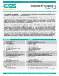
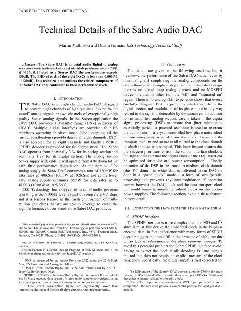
Some FFT data from <strong>the</strong> ES9008 (captured on <strong>the</strong> AP 2722<br />
system) are shown on <strong>the</strong> right. The upper plot (Figure 1)<br />
shows <strong>the</strong> THD. Note that <strong>the</strong> highest harmonic is <strong>the</strong> 5 th and<br />
is at about −120dB. (As mentioned in this note, this harmonic<br />
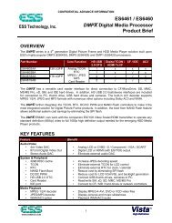
is due to <strong>the</strong> external amplifiers). The middle plot (Figure 2)<br />
shows <strong>the</strong> DNR performance with −60dB input signal.<br />
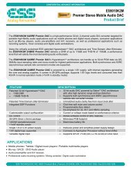
The lower plot (Figure 3) compares <strong>the</strong> jitter performance<br />
<strong>of</strong> a typical competitor’s part (red, or upper line) with <strong>the</strong><br />
<strong>Sabre</strong> <strong>DAC</strong> (blue, or lower line). The graph shows<br />
THD+Noise vs. Frequency with only 2nS <strong>of</strong> random jitter on<br />
<strong>the</strong> data transport clock (on <strong>the</strong> clock <strong>of</strong> <strong>the</strong> I 2 C in this<br />
example).<br />
ACKNOWLEDGMENT<br />
The entire team in <strong>the</strong> <strong>ESS</strong> Kelowna <strong>of</strong>fice have contributed<br />
to <strong>the</strong> <strong>Sabre</strong> <strong>DAC</strong> design, but special mention needs to be<br />
made <strong>of</strong> Dustin Forman who has led <strong>the</strong> <strong>DAC</strong> team and<br />
pushed this design through to <strong>the</strong> extraordinary level <strong>of</strong><br />
performance we are now able to deliver to <strong>the</strong> market.<br />
To <strong>the</strong> team in ShenZhen and Hong Kong who, in <strong>the</strong> early<br />
development <strong>of</strong> <strong>the</strong> HyperStream modulator were so<br />
demanding in <strong>the</strong>ir performance requirements and yet so<br />
helpful in getting our DVD based <strong>DAC</strong> products to acceptable<br />
levels.<br />
To Jason Heath, Frank Szabo and all <strong>the</strong> lab staff who<br />
evaluated <strong>the</strong> silicon and developed <strong>the</strong> PCB<br />
recommendations.<br />
To Khalid Arriani and his team who created <strong>the</strong> exceptional<br />
layout required for <strong>the</strong> <strong>Sabre</strong> <strong>DAC</strong>.<br />
To Bob Plachno and Calto Wong who respectively<br />
managed <strong>the</strong> schedule and kept us informed <strong>of</strong> key customer<br />
requirements, and finally, to Bob Blair who always believed in<br />
<strong>the</strong> Kelowna team and that this design would work.<br />
<strong>Audio</strong> Precision ES9008 10 @ 96000 I2S - Test 1 <strong>DAC</strong> FFT @ 0 dBFS<br />
d<br />
B<br />
r<br />
<strong>Audio</strong> Precision Figure 1: FFT with 0db input signal showing THD<br />
Sweep Trace Color Line ES9008 Style Thick 10 @ Data 96000 I2S Axis- Test Comment 2 <strong>DAC</strong> FFT @ -60 dBFS<br />
d<br />
A<br />
B<br />
r<br />
A<br />
+0<br />
-20<br />
-40<br />
-60<br />
-80<br />
-100<br />
-120<br />
-140<br />
-160<br />
-180<br />
10 20 50 100 200 500 1k 2k 5k 10k 20k 30k<br />
1 1 Blue Solid 2 Fft.Ch.1 Ampl Left ES9008 10 @ 96.0K I2S - Left Channel<br />
+0<br />
ES9008 10 @ 96000 I2S - Test 2 <strong>DAC</strong> FFT @ -60 dBFS<br />
-20 dBr A = 16.571 dBV, dBrB = 16.543 dBV<br />
ES9008 10 @ 96000 I2S - Test 1 <strong>DAC</strong> FFT @ 0 dBFS<br />
ES9008 10 @ 96000 I2S - Test 1 <strong>DAC</strong> FFT @ 0 dBFS.at27<br />
Figure 2: FFT with input at -60db showing DNR<br />
1 1 Blue Solid 2 Fft.Ch.1 Ampl Left ES9008 10 @ 96.0K I2S - Left Channel<br />
<strong>Audio</strong> Precision THD+N VS Frequency with 2nS Random Jitter<br />
12/19/07 11:54:17<br />
d<br />
B<br />
-40<br />
-60<br />
-80<br />
-100<br />
-120<br />
-140<br />
-160<br />
-180<br />
10 20 50 100 200 500 1k 2k 5k 10k 20k 30k<br />
-70<br />
-72.5<br />
-75<br />
-77.5<br />
-80<br />
-82.5<br />
-85<br />
-87.5<br />
-90<br />
-92.5<br />
-95<br />
-97.5<br />
-100<br />
-102.5<br />
-105<br />
-107.5<br />
-110<br />
-112.5<br />
-115<br />
-117.5<br />
-120<br />
-122.5<br />
-125<br />
-127.5<br />
-130<br />
Sweep Trace Color Line Style Thick Data Axis Comment<br />
dBr A = 16.571 dBV, dBrB = 16.543 dBV<br />
Sweep Trace Color Line Style Thick Data Axis Comment<br />
1 1 Red Solid 4 Anlr.THD+N Ratio Left Competitor<br />
2 1 Blue Solid 4 Anlr.THD+N Ratio Left <strong>Sabre</strong>_8<br />
ES9008 10 @ 96000 I2S - Test 2 <strong>DAC</strong> FFT @ -60 dBFS.at27<br />
Figure 3: The effect <strong>of</strong> 2nS Jitter on THD+Noise vs. Frequency. The upper<br />
line is a typical competitor’s part and <strong>the</strong> lower line is <strong>the</strong> <strong>Sabre</strong> <strong>DAC</strong>.<br />
Hz<br />
20 50 100 200 500 1k 2k 5k 10k<br />
20k<br />
Hz<br />
<strong>Sabre</strong>8_VS_CS4398_THD+N_VS_Freg_2nsRondom_Jitter.at27<br />
Hz<br />
5<br />
+0<br />
-20<br />
-40<br />
-60<br />
-80<br />
-100<br />
-120<br />
-140<br />
-160<br />
-180<br />
+0<br />
-20<br />
-40<br />
-60<br />
-80<br />
-100<br />
-120<br />
-140<br />
-160<br />
-180