1202-VLZ PRO 12-Channel Mic/Line Mixer Spec Sheet - Mackie
1202-VLZ PRO 12-Channel Mic/Line Mixer Spec Sheet - Mackie
1202-VLZ PRO 12-Channel Mic/Line Mixer Spec Sheet - Mackie

You also want an ePaper? Increase the reach of your titles
YUMPU automatically turns print PDFs into web optimized ePapers that Google loves.
Introduction<br />
The <strong><strong>12</strong>02</strong>-<strong>VLZ</strong> <strong>PRO</strong> is the updated, upgraded version<br />
of <strong>Mackie</strong>’s classic <strong>12</strong>-channel compact mic/line<br />
mixer. The unit incorporates <strong>Mackie</strong>’s new ultra-high<br />
quality XDR (Extended Dynamic Range) mic preamps<br />
with the best RFI rejection of any compact mixer<br />
design. Added benefi ts include maximum freedom<br />
from ground loops and impeccable sonic performance<br />
that meets or exceeds the specs of esoteric, outboard<br />
mic preamplifi ers. The XDR design is the only compact<br />
mixer mic preamp that is totally impedance independent:<br />
frequency response does not change even with<br />
extremely long cable runs or exceptionally high-impedance<br />
mic inputs.<br />
To greatly reduce the effects of wind noise and mic<br />
thumps, each of the four mic channels has a sharp,<br />
18dB/octave, 75Hz Low Cut fi lter.<br />
Mute/Alt 3-4 effectively creates a second stereo bus.<br />
The Mute button on each channel mutes that channel in<br />
the Main Mix, but also acts as a router to the 3-4 stereo<br />
bus, greatly increasing signal routing fl exibility.<br />
The EFX to Monitor feature allows routing of reverb or<br />
other effects signals back into a monitor mix via Aux Send 1.<br />
Aux 1’s Pre/Post switch can be set for pre-fader/post-EQ<br />
use, which is benefi cial for stage monitor mixes, or postfader/post-EQ<br />
for use with external effects. It also has a<br />
level control for added fl exibility.<br />
Control Room/Phones has its own level control,<br />
outputs and input matrix for selecting any combination<br />
of Main Mix, Tape In and Alt 3-4 to create custom<br />
headphone mixes, to monitor tape levels, and more.<br />
A separate switch routes this multi-source signal back<br />
into the Main Mix.<br />
Because of its many features and durability, the<br />
<strong><strong>12</strong>02</strong>-<strong>VLZ</strong> <strong>PRO</strong> can be used for extra studio-grade preamps,<br />
as aux inputs for a mixing console, or as an<br />
impedance- or level-matching audio toolkit.<br />
RM<strong><strong>12</strong>02</strong>-<strong>VLZ</strong> Rack-mount brackets (not included),<br />
1402-<strong>VLZ</strong> <strong>PRO</strong> 14-<strong>Channel</strong> <strong>Mic</strong>/<strong>Line</strong> <strong>Mixer</strong>, 1604-<strong>VLZ</strong><br />
<strong>PRO</strong> 16-<strong>Channel</strong> <strong>Mic</strong>/<strong>Line</strong> <strong>Mixer</strong>, 1642-<strong>VLZ</strong> <strong>PRO</strong> 16-<strong>Channel</strong><br />
<strong>Mic</strong>/<strong>Line</strong> <strong>Mixer</strong>, SRM350/SRM450 Active 2-Way SR<br />
Loudspeakers, M 800/M 1400i/M 1400 Power Amplifi<br />
ers, C200/C300z passive 2-way SR Loudspeakers<br />
<strong>12</strong>-<strong>Channel</strong> <strong>Mic</strong>/<strong>Line</strong> <strong>Mixer</strong><br />
Features<br />
4 low noise, high headroom XDR (Extended<br />
Dynamic Range) XLR mic inputs with the best<br />
RF rejection of any compact mixer available and<br />
maximum freedom from ground loops<br />
4 balanced/unbalanced mono line inputs<br />
4 pairs of balanced/unbalanced stereo line inputs<br />
48V global phantom power<br />
3-Band EQ (<strong>12</strong>kHz, 2.5kHz, 80Hz)<br />
75Hz, 18dB/octave Low Cut fi lters on <strong>Channel</strong>s 1–4<br />
PFL Solo on all channels<br />
Very Low Impedance (<strong>VLZ</strong>) architecture<br />
EFX to Monitor switch<br />
Alt 3-4 extra stereo bus<br />
Balanced inputs and outputs (except RCAs,<br />
phones and inserts)<br />
Balanced XLR Main L/R outputs with mic/line<br />
level switch, plus 1/4" (TRS) Main L/R outputs<br />
60dB Gain on <strong>Channel</strong>s 1–4<br />
Global Aux 1 Pre/Post-Fader switch<br />
Level Set LED and marker<br />
Applications<br />
Live sound mixing: small churches, clubs,<br />
school auditoriums, school sports centers,<br />
conference centers, boardrooms, trade<br />
shows, presentations<br />
Studio and fi eld recording<br />
Multimedia applications: A/V presentations,<br />
video post production, CD authoring<br />
Broadcast: live remotes, ENG, ad production
<strong>Spec</strong>ifi cations<br />
<strong>Mic</strong> Preamp<br />
Equivalent Input Noise (20Hz–20kHz):<br />
150Ω –<strong>12</strong>9.5dBu<br />
50Ω –131.0dBu<br />
0Ω –134.5dBu<br />
Frequency Response:<br />
–1dB 5Hz–100kHz<br />
–3dB 3Hz–192kHz<br />
IM Distortion (4 to 1 ratio SMPTE)<br />
35dB gain 0.0008%<br />
Harmonic Distortion (20Hz–20kHz)<br />
35dB gain 0.0007%<br />
Gain<br />
Max +60dB<br />
Min 0dB or Unity<br />
Max Input +22dB<br />
Input Impedance 1.3kΩ<br />
Common Mode Rejection > 90dB<br />
Common Mode Rejection Ratio > 140dB<br />
Main Mix Noise 1<br />
Main Mix down, ch. Gain down: –104dB<br />
Main Mix @ unity, ch. Gain down: –90.5dB<br />
Main Mix knob @ unity, ch. Gain @ unity: –88.5dB<br />
Total Harmonic Distortion (THD) 2<br />
0.005%<br />
Attenuation (Crosstalk) 3<br />
Main Mix knob down: –85dBu<br />
<strong>Channel</strong> Mute/Alt 3-4 switch engaged: –84dBu<br />
<strong>Channel</strong> Gain knob down: –83dBu<br />
Frequency Response 4<br />
20Hz to 60kHz: +0dB/–1dB<br />
20Hz to 100kHz: +0dB/–3dB<br />
Maximum Levels<br />
<strong>Mic</strong> input: +22dBu<br />
Tape input: +16dBu<br />
All other inputs: +22dBu<br />
Main Mix XLR outputs: +28dBu<br />
All other outputs: +22dBu<br />
Impedances<br />
<strong>Mic</strong> input: 1.3kΩ<br />
<strong>Channel</strong> Insert return: 2.5kΩ<br />
All other inputs: > 10kΩ<br />
Tape output: 1.1kΩ<br />
All other outputs: <strong>12</strong>0Ω<br />
EQ<br />
High Shelving: ±15db @ <strong>12</strong>kHz<br />
Mid Peaking: ±<strong>12</strong>dB @ 2.5kHz<br />
Low Shelving: ±15db @ 80Hz<br />
Power Consumption<br />
<strong>12</strong>0VAC, 50/60Hz, 25 Watts<br />
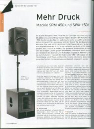
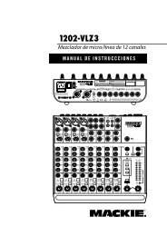
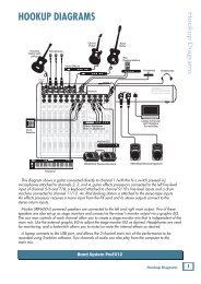
Physical<br />
Weight: 6 lbs. 8 oz. (3 kg)<br />
Dimensions: 11.8" x 11.2" x 2.6"<br />
(300mm x 284mm x 66mm)<br />
6 rack<br />
spaces<br />
11.2"<br />
(284mm)<br />
11.8" (300mm)<br />
19" (483mm)<br />
with optional rack ears (RM<strong><strong>12</strong>02</strong>-<strong>VLZ</strong>)<br />
11.2" (284mm)<br />
11.8" (300mm)<br />
2.6"<br />
(66mm)<br />
2.6"<br />
(66mm)<br />
<strong>Spec</strong>ifi cations footnotes:<br />
1) 20Hz–20kHz bandwidth, 1/4" Main out, channels 1–4 Trim @ unity gain, channel EQs fl at, all<br />
channels assigned to Main Mix, channels 1 and 3 Pan left, 2 and 4 Pan right. Reference +4dBu.<br />
2) 1kHz @ +14dBu, 20Hz–20kHz.<br />
3) 1kHz relative to 0dBu, 20Hz–20kHz bandwidth, <strong>Line</strong> in, 1⁄4" Main Out, Trim @ unity.<br />
4) Any input to any output.
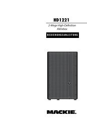
TAPE OUT L<br />
LOGIC<br />
SOLO<br />
AUX SEND 2 POST<br />
AUX SEND 1 POST<br />
AUX SEND 1 PRE<br />
ALT R<br />
ALT L<br />
MAIN R<br />
MAIN L<br />
PHANTOM POWER<br />
INSERT<br />
LINE OUT L<br />
GAIN PAN MAIN / ALT<br />
TRIM<br />
MID HI<br />
LO<br />
2<br />
2<br />
80 2K5 <strong>12</strong>K<br />
75Hz<br />
HPF<br />
1<br />
BAL OUT L<br />
MIC IN<br />
1<br />
LO CUT<br />
3<br />
3<br />
30dB PAD<br />
MAIN<br />
LEVEL<br />
MAIN MIX<br />
3-BAND EQ<br />
MONO CHANNEL<br />
(1 OF 4)<br />
LINE IN<br />
2<br />
BAL OUT R<br />
AUX<br />
SENDS<br />
1<br />
3<br />
LINE OUT R<br />
ALT MIX<br />
SOLO (PFL)<br />
3-BAND EQ<br />
MAIN / ALT<br />
MID HI<br />
LO<br />
TAPE OUT R<br />
ALT OUT L<br />
LINE IN L<br />
80 2K5 <strong>12</strong>K<br />
28<br />
10<br />
7<br />
4<br />
2<br />
0<br />
2<br />
4<br />
7<br />
10<br />
20<br />
30<br />
ALT OUT R<br />
GAIN PAN<br />
STEREO CHANNEL<br />
(1 OF 4)<br />
METERING<br />
(0dBu = 0VU)<br />
MID HI<br />
LO<br />
SOURCE<br />
ALT<br />
LINE IN R<br />
AUX 2<br />
80 2K5 <strong>12</strong>K<br />
RUDE SOLO LED<br />
TAPE IN<br />
+6dB<br />
L<br />
TAPE<br />
R<br />
CONTROL ROOM &<br />
PHONES LEVEL<br />
CONTROL ROOM &<br />
PHONES MIX<br />
AUX 1<br />
MAIN<br />
SOLO (PFL)<br />
L IN<br />
(MONO)<br />
SOLO<br />
RELAY<br />
GAIN<br />
AUX RETURN 1<br />
SOLO MIX<br />
R IN<br />
ASSIGN TO MAIN<br />
PHONES OUT<br />
L IN<br />
LEFT<br />
AUX 1<br />
PRE / POST<br />
GAIN<br />
AUX RETURN 2<br />
RIGHT<br />
AUX 1 LEVEL<br />
R IN<br />
CONTROL ROOM OUT<br />
AUX SEND 1<br />
AUX MIX<br />
AUX SEND 2<br />
EFX TO MONITOR
Architect’ and Engineer’s <strong>Spec</strong>ifi cations<br />
1. GENERAL CONFIGURATION. The mixer shall<br />
accommodate 4 microphone signals: mono channels<br />
1–4; <strong>12</strong> line signals: mono channels 1–4 and<br />
stereo channels 5–<strong>12</strong>; 2 stereo pairs of Aux Return<br />
inputs; 4 Send/Return channel Inserts; 2 stereo<br />
pairs of Main Mix outputs; 1 stereo pair of RCA-type<br />
Tape Inputs; 1 stereo pair of RCA-type Tape Outputs;<br />
1 stereo pair of Control Room outputs; 1<br />
stereo pair of Alt 3-4 outputs; 2 Aux Send outputs;<br />
and 1 stereo headphone output. The mixer shall be<br />
capable of placement on a table or installation in<br />
a standard 19-inch rack mount (using optional rack<br />
rail brackets) and shall be entirely self-contained.<br />
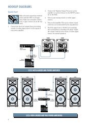
2. MIXER INPUTS.<br />
MONO CHANNELS 1–4: The mixer shall include 4<br />
XDR electronically balanced mic inputs, using XLR-<br />
3-F-type connectors, accepting nominal levels from<br />
–60dBu to +4dBu via 4 rotary Trim controls. 48V<br />
phantom power shall be available via a globally-controlled<br />
rocker-type switch. 4 balanced or unbalanced<br />
line inputs shall be wired in parallel, using 1/4" TRS<br />
phone jacks, accepting nominal levels from –45dBu<br />
to +4dBu. The mixer shall include 4 channel Inserts<br />
using 1/4" TRS phone jacks (tip=send, ring=return,<br />
sleeve=ground), delivering and accepting nominal<br />
levels from –10dBV to +4dBu.<br />
STEREO CHANNELS 5/6, 7/8, 9/10 and 11/<strong>12</strong>: The<br />
mixer shall include 8 bal/unbal line inputs, forming 4<br />
stereo input pairs, using 1/4" TRS phone jacks and<br />
accepting nominal levels from –10dBV to +4dBu.<br />
OTHER INPUTS: The mixer shall include 4 bal/unbal<br />
Aux Return inputs, forming two stereo pairs, using<br />
1/4" TRS phone jacks and accepting nominal levels<br />
from –10dBV to +4dBu. The mixer shall include 1<br />
stereo pair of Tape In jacks, using unbalanced RCAtype<br />
phono jacks, accepting nominal levels from<br />
–20dBV to +4dBu.<br />
3. MIXER OUTPUTS.<br />
MAIN OUTPUTS: The mixer’s Main Output stereo<br />
pairs shall be fi tted in three ways: Using balanced<br />
XLR-3-M-type connectors, maximum output of<br />
+28dBu, including 1 Main Output Level switch to<br />
provide 30dB attenuation (XLR outputs only); using<br />
bal/unbal 1/4" TRS phone jacks, delivering nominal<br />
levels from –10dBV to +4dBu; and using unbalanced<br />
RCA-type phono jacks (labeled TAPE OUT)<br />
delivering nominal levels from –10dBV to +4dBu.<br />
OTHER OUTPUTS: The mixer shall include 1<br />
stereo pair of Alt 3-4 outputs using bal/unbal 1/4"<br />
TRS phone jacks, delivering nominal levels from<br />
–10dBV to +4dBu; 1 stereo pair of Control Room outputs<br />
using bal/unbal 1/4" TRS phone jacks, delivering<br />
nominal levels from –10dBV to +4dBu; 2 Aux<br />
Send outputs using bal/unbal 1/4" TRS phone jacks,<br />
delivering nominal levels from –10dBV to +4dBu;<br />
and 1 stereo Headphones output using an unbalanced<br />
1/4" TRS phone jack (tip=left, ring=right,<br />
sleeve=ground).<br />
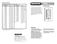
4. MIXER INPUT SECTION. Each channel shall include<br />
1 rotary Trim control; 1 Low Cut fi lter (HPF), providing<br />
an 18dB per octave curve starting at 75Hz; 2 rotary<br />
Aux Send controls, providing up to 15dB above unity<br />
gain; 3 rotary equalization (EQ) controls: +15dB @<br />
<strong>12</strong>kHz shelving, +<strong>12</strong>dB @ 2.5kHz peaking and +15dB<br />
@ 80kHz shelving; 1 rotary Pan control, 4dB attenuation<br />
panned center; 1 Mute/Alt 3-4 switch, to be<br />
used as a channel mute or to route the signal to the<br />
alternate stereo bus (Alt 3-4); 1 PFL (Pre-Fader Listen<br />
solo) switch; and 1 rotary channel Gain control, providing<br />
up to 20dB above unity gain. Note: The stereo channels<br />
(5/6, 7/8, 9/10 and 11/<strong>12</strong>) shall not include the<br />
Trim or Low Cut controls.<br />
5. MIXER OUTPUT SECTION. The mixer shall have 1<br />
rotary Main Mix control, providing up to 10dB above<br />
unity gain; 1 rotary Control Room/Phones control,<br />
providing up to 10dB above unity gain; 1 Source<br />
Matrix including 3 switches to deliver any combination<br />
of stereo signals to the Control Room, Phones<br />
and Meters, including Main Mix, Alt 3-4 and Tape,<br />
which shall be replaced by any solo signals resulting<br />
from the engagement of any channel’s PFL switch;<br />
1 Assign to Main Mix switch to deliver the Source<br />
Matrix signals to the Main Mix; 2 rotary Aux Return<br />
level controls, providing up to 20dB above unity<br />
gain; 1 rotary Aux Send 1 Master control, providing<br />
up to 10dB above unity gain; 1 Aux Send 1 global<br />
Pre/Post switch; 1 EFX to Monitor switch, allowing<br />
Aux Return 1 signals to be delivered to Aux Send 1<br />
via the Aux Return 2 level control; and 1 blinking red<br />
Solo LED, to indicate a solo condition.<br />
6. METERING. The mixer shall include 1 stereo <strong>12</strong>-segment<br />
LED meter with points at –30, –20, –10, –7, –4, –2, 0, +2,<br />
+4, +7, +10 and 28dB (clip). The source signals for the meters<br />
shall be the same signals selected in the Source Matrix, and<br />
a solo condition shall replace the Source selection with the<br />
soloed channel(s). The meters shall be calibrated so that a<br />
0dBu signal at the Control Room output shall be indicated<br />
as 0dB on the meters, ±1dB.
7. PHYSICAL CONFIGURATION. The mixer shall be<br />
made of steel, painted dark gray with light gray graphics.<br />
The mixer’s dimensions shall be 2.6" (66mm) in<br />
height, 11.8" (300mm) in width and 11.2" (284mm) in<br />
depth, as viewed horizontally. The mixer shall weigh 6<br />
lbs, 8 oz (14.3 kg). Optional RM<strong><strong>12</strong>02</strong>-<strong>VLZ</strong> rack-mount<br />
brackets shall allow the mixer to be mounted in a rack<br />
system, with either the chassis top or the control knobs’<br />
tops to be fl ush with the rack rail.<br />
8. SPECIFICATIONS. In addition to specifi cations<br />
already cited, the mixer shall meet or exceed<br />
the following specifi cations: Frequency response:<br />
microphone input to any output, 20Hz to 60kHz,<br />
+0dB/–1dB; Total Harmonic Distortion (THD): 1Khz<br />
@ +14dBu, 0.0007%; Equivalent Input Noise (EIN):<br />
microphone input to insert send, –<strong>12</strong>9.5dBm:<br />
Common Mode Rejection (CMR): microphone input to<br />
insert send, maximum gain, 1kHz, better than 90dB;<br />
Typical Main Output noise: all channels assigned,<br />
channels 1 and 3 panned left, channels 2 and 4<br />
panned right, main mix @ unity, channel gain @<br />
unity, –86dBu; Signal to Noise ratio: ref +4dBu operating<br />
level, 90dB; Attenuation: ref. 0dB @ 1kHz,<br />
Main Mix level control down, –85dBu; channel<br />
Mute engaged, –84dBu; channel Gain control down,<br />
–83dBu; Input impedance: microphones input,<br />
1.3kΩ; channel Insert return, 2.5kΩ; all other inputs,<br />
greater than 10kΩ; Output impedance: Tape Out,<br />
1.1kΩ; all other outputs, <strong>12</strong>0Ω.<br />
The mixer shall be a <strong>Mackie</strong> <strong><strong>12</strong>02</strong>-<strong>VLZ</strong> <strong>PRO</strong>.<br />
www.mackie.com<br />
16220 Wood-Red Road NE, Woodinville, WA 98072 USA<br />
800.898.3211, fax 425.487.4337, sales@mackie.com<br />
UK +44.<strong>12</strong>68.570.808, fax +44.<strong>12</strong>68.570.809, uk@mackie.com<br />
FILES FOR DOWNLOADING<br />
<strong><strong>12</strong>02</strong><strong>VLZ</strong>P.PDF this specifi cation sheet<br />
<strong><strong>12</strong>02</strong>AE.TXT text version of Architect’s and<br />
Engineer’s <strong>Spec</strong>ifi cations for insertion into proposals<br />
LOUD Technologies continually engages in research related to product improvement. New<br />
material, production methods, and design refi nements are introduced into existing products<br />
without notice as a routine expression of that philosophy. For this reason, any current LOUD<br />
Technologies product may differ in some respect from its published description, but will<br />
always equal or exceed the original design specifi cations unless otherwise stated. ©1999-<br />
2004 LOUD Technologies Inc. All rights reserved.<br />
Part No. 091-294-00 Rev. B