
You also want an ePaper? Increase the reach of your titles
YUMPU automatically turns print PDFs into web optimized ePapers that Google loves.
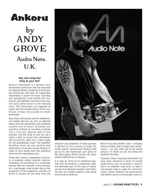
<strong>Ankoru</strong><br />
by<br />
ANDY<br />
GROVE<br />
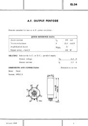
Audio Note,<br />
U.K.<br />
Hey, don’t drop that<br />
thing on your foot!<br />
Musical information is a dynamic four<br />
dimensional continuum, like the one posed<br />
by relativity theory, consisting of three spatial<br />
dimensions and time, all inseparably<br />
interrelated. A system for music recording<br />
and reproduction must transfer this continuum<br />
and faithfully reconstruct the original<br />
sonic performance in the listening<br />
room. Test instruments are supposed to<br />
ensure that the transformation of the continuum<br />
is linear and accurate to certain<br />
parameters.<br />
Alas, these instruments and the mathematical<br />
models that we use, such as relativity<br />
theory, lack the spontaneity and emotional<br />
content vital to music. Somehow our<br />
primitive method of recording scratches<br />
into a vinyl disc captures some of this<br />
emotion, and the lump of rock we call a<br />
stylus is able to extract the information<br />
and convert the vibes into a signal ready<br />
for the amplification chain. The amplifier,<br />
therefore, must not only perform well<br />
electrically. It must also convey emotion in<br />
order to fully satisfy both the analytical<br />
mind and the inspirational soul.<br />
These days, science is beginning to discover<br />
an essential, almost mystical, interconnectedness<br />
of everything. It is intuitively<br />
obvious that the character of the universe<br />
on a macroscopic scale should rely on the<br />
properties of the subatomic particles of<br />
which it consists. At the same time, the<br />
character and properties of those particles<br />
is defined by the universe at large, the<br />
whole system mysteriously holding itself<br />
up by it’s own bootstraps, each piece of<br />
the giant jigsaw fitting exactly into place<br />
without deficiencies or excesses.<br />
It is only by virtue of an intellectual gesture<br />
that we perceive a condensed, solid,<br />
and definable part of the web of reality,<br />
yet we have deceived ourselves into thinking<br />
that our mental creation is the be-all<br />
and end-all of existence.<br />
Most of our old scientific “laws”– including<br />
those currently used to judge sonic performance<br />
– are only close ups of the whole<br />
picture. I’m afraid we are not seeing the<br />
wood for the trees.<br />
Certainly these measured parameters do<br />
have some relevance in terms of overall<br />
performance, but to recreate a musical<br />
event, an amplifier must work on both a<br />
macroscopic scale as a part of a communication<br />
system between the performance<br />
and listener and on a microscopic level as a<br />
Issue <strong>12</strong> - SOUND PRACTICES 9
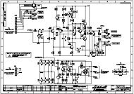
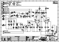
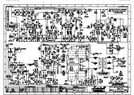
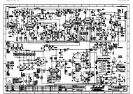
Schematic diagram of author’s design - Audio Note <strong>Ankoru</strong> SE parallel 845 70 Watter<br />
collection of valves and parts which must<br />
be tamed and optimized for the task at<br />
hand.<br />
A magazine article can only skim the surface<br />
of any design philosophy and, of<br />
course, there will be shouts of “what the<br />
*@$! is this guy on?”, but I hope my discussion<br />
of the <strong>Ankoru</strong> design will be interesting<br />
nonetheless.<br />
Starting with the basic precept that each<br />
part of the amplifier should fit exactly into<br />
place, and have a character defined by the<br />
overall requirements of the system, the<br />
validity of feedback and push pull operation,<br />
two pillars of traditional amplifier<br />
design, are immediately called into question.<br />
These concepts are purely intellectual<br />
constructions, created in laboratorieswith<br />
no motivation from natural music, and I<br />
am convinced that they detract from<br />
sound quality as a result.<br />
10 SOUND PRACTICES - Issue <strong>12</strong><br />
In practice, the ultimate purpose of feedback<br />
and push pull operation is to make<br />
amplifiers easier to make not better. In any<br />
event, reducing harmonic distortion to<br />
vanishingly small levels and increasing<br />
bandwidth from DC to cosmic rays does<br />
not make a more musically satisfying<br />
amplifier. Specs must give some satisfaction<br />
though, ‘cos we all know a guy who<br />
slinks off to the bathroom with a copy of<br />
his tranny amp spec sheet!<br />
I agree that limitations such as distortion<br />
and bandwidth abberations unquestionably<br />
colour the sound and should be eliminated,<br />
but beyond that I maintain that<br />
there are more important areas to be considered<br />
if musicality is the ultimate goal.<br />
According to my way of thinking, all of the<br />
above leads to the assertion that the overall<br />
topology of an amplifier must be singleended<br />
and there must be no feedback.<br />
Transistors and all things silicon sound<br />
unnatural…put sand in the signal path and<br />
you get gritty sound! So, let’s proceed<br />
directly to valves and, in particular, the<br />
simplest and purest amplifying device.<br />
The materials used for the construction of<br />
the passive elements of the amplifier are<br />
just as important since the signal must pass<br />
through them. Every material has a tonal<br />
coloring effect, so only highly-specified,<br />
high-purity, listening-tested materials are<br />
suitable.<br />
For example, in the <strong>Ankoru</strong> we use only<br />
Black Gate and Cerafine electrolytic<br />
capacitors for the audio circuitry. These<br />
caps eliminate that electrolytic mushiness<br />
without going over to the brashness of certain<br />
plastic caps. The valve selection was<br />
guided by the notion that the different<br />
sonic signatures of each type should be<br />
complimentary, leading to the goal of a<br />
sound that possesses both strength and<br />
finesse.
Before I go on to describe the <strong>Ankoru</strong> circuit<br />
in detail, I would like to say a few<br />
words about transformers and transformer<br />
coupling, since transformers play an<br />
important role in the design.<br />
In any valve, waveform distortion is caused<br />
by the characteristic parameters of the<br />
valve changing in sympathy with the<br />
applied signal. In a standard RC coupled<br />
triode circuit, the valve is set up with a<br />
quiescent current (Iq) flowing through it<br />
and the load resistor, yielding a particular<br />
quiescent voltage on its anode (Vq).<br />
With a negative-going input signal, the<br />
current is reduced and the anode swings<br />
positive due to the reduced voltage drop<br />
across the load resistor (Rl X Iq). The<br />
reverse is true with a positive-going input<br />
signal, the valve’s anode current is<br />
increased so the voltage on it reduces due<br />
to increased drop across Rl.<br />
There is a problem with this, however,<br />
because as the anode swings positive and<br />
the current decreases, the transconductance<br />
of a valve goes down due to the curvature<br />
of its characterisic. Of course, the<br />
reverse is true with a positive-going input<br />
signal, the transconductance goes up with<br />
with the current.<br />
This means that the positive part of the<br />
anode swing is compressed and the negative<br />
part is expanded– waveform distortion.<br />
Usually, this distortion only becomes<br />
serious with very non-linear valves and/or<br />
large voltage swings. When we want to<br />
drive a fairly meaty output valve we need<br />
to swing a lot of volts because the mu of<br />
these types is necessarily low to keep the<br />
anode impedance down to keep loudspeaker<br />
damping up. In this circumstance,<br />
waveform distortion can easily rear its<br />
rather ugly head.<br />
We need a system for keeping the current<br />
through the valve as constant as possible<br />
over the anode swing, i.e., a high load<br />
impedance. Increasing the load resistor on<br />
an RC coupled stage can only go so far,<br />
however. One soon runs into problems of<br />
resistor dissipation and PSU voltage if the<br />
anode current is kept at the optimum<br />
level.<br />
The SRPP stage and his other active<br />
loaded cousins, such as the mu follower,<br />
have never really delivered the goods for<br />
me. Close listening reveals a lack of focus<br />
and immediacy compared to even the<br />
humble RC coupled stage. Anyway SRPP<br />
is a feedback device and quite often that<br />
scheme doesn’t work very well electrically<br />
either, especially with the low impedance<br />
valves we would like to use as drivers.<br />
Simply pretending that you’ve got a low<br />
output impedance just doesn’t cut any ice<br />
in the world of real audio.<br />
For large power valves, a low AC drive<br />
impedance is necessary because large<br />
valves have large and therefore highly<br />
capacitive grids. Thankfully, the low gain<br />
keeps down the Miller Effect, but it’s still<br />
there, so for good HF response, there is no<br />
getting around using a good low impedance<br />
driver.<br />
From the standpoint of sound quality, for a<br />
strong sound we need a beefy, low impedance<br />
driver. Wimpy driver equals wimpy<br />
sound. <strong>Dr</strong>ive two 845s with an ECC83<br />
and it’ll be like putting a model aircraft<br />
engine in a Chevy Impala. Not exactly awe<br />
inspiring.<br />
The DC resistance of the grid circuit must<br />
also be kept low to control the effect of<br />
another rather annoying bugbear, grid current.<br />
Unfortunately, the vacuum in many<br />
modern valves is far from perfect, so there<br />
are quite a few gas ions floating around<br />
inside the bottle. Some of these ions will<br />
collide with the grid and draw electrons<br />
from the grid circuit. If the grid resistance<br />
is high, the grid bias will be modulated in<br />
tune with the signal, a real no-no in my<br />
book.<br />
Also the grid may occasionally be driven<br />
positive on signal peaks, causing the gridcathode<br />
diode to conduct, rectifying the<br />
input voltage in the manner of a shunt<br />
diode supply with the coupling cap as the<br />
reservoir. This action makes the bias voltage<br />
more negative, reducing the quiescent<br />
current through the tube, sometimes to<br />
the point where it will only conduct on<br />
peaks (Class C). In fact, a severe peak can<br />
cause the amp to cut off altogether, resulting<br />
in a total loss of output.<br />
Worse still, the grid resistor/coupling cap<br />
combination acts as an RC time constant,<br />
so the effect lasts for some<br />
time after the<br />
overload<br />
h a s<br />
passed<br />
in sort<br />
of<br />
a time-delay distortion mechanism.<br />
Reducing the grid resistor to combat these<br />
effects is no solution. We want a DC grid<br />
resistance similar in magnitude to the<br />
impedance of the driver valve, i.e. a few<br />
hundred ohms not a few hundred kilohms.<br />
Making your grid resistor 600 ohms will<br />
likely kill the driver stage and, anyway,<br />
would require a coupling capacitor so big<br />
that the RC time constant would put us<br />
right back where we started.<br />
To cure the voltage swing problem<br />
requires a circuit element which has low<br />
DC drop but a high AC impedance. Plus,<br />
we need a low DC resistance in the grid of<br />
the output valve. And the device should<br />
efficiently couple the driver valve to the<br />
output tube’s grid.<br />
The driver transformer is exactly what we<br />
need for the job. Its primary inductance<br />
presents an extremely high AC impedance<br />
to the driver valve and reflects the anode<br />
impedance of the driver into the grid circuit<br />
of the output valve. A good driver<br />
trans will have a primary and secondary<br />
DC resistance on the order of 300 ohms,<br />
so the problems associated with grid current<br />
are more or less eliminated. This is a<br />
resistance 1000 times lower than I’ve seen<br />
in some designs.<br />
Ideally, the transformer secondary is left<br />
unloaded, i.e. there is no “damping resistor”<br />
put across it to cut ringing. An<br />
unloaded transformer sounds better and it<br />
gives the driver valve a higher impedance<br />
load.<br />
There are two large-scale problems with<br />
driver transformers, HF frequency<br />
response and LF frequency response. These<br />
two requirements are mutually exclusive<br />
to a certain degree and many commercially<br />
available transformers sacrifice one for the<br />
other. The Tango transformers, for example,<br />
seem to go for impressive-looking HF<br />
specs but they have diminutive primary<br />
inductances<br />
Issue <strong>12</strong> - SOUND PRACTICES 11
which limit the LF performance.<br />
The problem is compounded by the unbalanced<br />
DC current imposed by SE operation,<br />
which requires that the number of<br />
primary turns must be increased to counterbalance<br />
the loss of permeability caused<br />
by the air gap in the core. Leakage inductance<br />
is proportional to the square of the<br />
primary turns so it’s a real pain in the butt.<br />
The driver transformer in the <strong>Ankoru</strong> has<br />
to handle 45 mA and still have superb<br />
bass, so it took some heavy calculator work<br />
and a few trees worth of paper to get it all<br />
working! [The <strong>Ankoru</strong> interstage trans will<br />
be available as a DIY part–ed.]<br />
I love the sound of large triodes like the<br />
211 and 845. The 845 was used in this<br />
amp because it offers greater power in<br />
Class A1. The 211 is a more voltage sensitive<br />
valve than the 845, its mu is higher<br />
but then so is its internal impedance. It<br />
can’t swing a lot of current at the low voltage<br />
end of the anode swing without having<br />
the grid driven positive into Class A2.<br />
When pushing the grid above zero volts, it<br />
no longer reacts as a high-impedance terminal.<br />
It starts to draw appreciable current,<br />
corrupting the input signal in a most<br />
unattractive way unless the driver impedance<br />
is extremely low.<br />
The grid-cathode diode impedance of a<br />
211 is about 2k, so we would need something<br />
around 100 times lower or hideous<br />
distortion would result. The waveform distortion<br />
could be corrected using feedback<br />
but why build an amplifier that is intrinsically<br />
nonlinear?<br />
The 845 can sink a lot more juice where<br />
the 211 starts wheezing, but since the mu<br />
is so low, it requires a driver stage capable<br />
of considerable voltage swing. The 845s in<br />
the <strong>Ankoru</strong> are biased at -100 to -200<br />
Volts for an anode current of 75 mA at<br />
<strong>12</strong>00V B+, they look into a load impedance<br />
of around 6k, and put out a formidable<br />
70 Watts. The output transformer has<br />
to cope with 150 mA DC and hold its 6k<br />
impedance down at LF, requiring a high<br />
primary inductance. This takes a serious<br />
hunk of iron, but the <strong>Ankoru</strong> output is just<br />
such a beast and the bass is awesome, if I<br />
do say so myself.<br />
To keep the drive signal to the output<br />
valves clean requires a driver valve of<br />
excellent linearity. One could use an indirectly<br />
heated valve such as the 6BX7, very<br />
linear, or the slightly less linear 6BL7, but<br />
low impedance, low mu directly heated<br />
valves are definitely the best choice.<br />
<strong>12</strong> SOUND PRACTICES - Issue <strong>12</strong><br />
Since this amp has to be built using valves<br />
which will be available for some time into<br />
the future, so that replacements can be<br />
made throughout its life, it was necessary<br />
to use modern versions of either the 2A3<br />
or 300B. I originally experimented with<br />
the 2A3 as I wanted a measure of its clarity<br />
and immediacy, but these valves have a<br />
very nasty habit of making toilet related<br />
noises even in the output stages of amps,<br />
and using one as a driver was impossible. I<br />
even tried some NOS samples but many<br />
were only marginally better, only the best<br />
and therefore rare and expensive examples<br />
were quiet.<br />
So the 300B was chosen, and it brought its<br />
characteristic warmth and musicality to<br />
the amp as well a greater impact to the<br />
bass. The 300B is operated with 300V<br />
across it and an anode current of 45 mA so<br />
it will last for ages, no more current or<br />
voltage was necessary for driving the 845s<br />
to full output. The 300B’s output is in fact<br />
so large that the 845s will be freaking (and<br />
so will your wife and the neighbours)<br />
before it runs into trouble which makes its<br />
jobs and the job of the input stage easier.<br />
Various input configurations were tried, all<br />
using the E182CC/7044 valve for its powerful<br />
sound. The original and best sounding<br />
configuration gave the amp so much<br />
gain as to be impractical. Long speaker<br />
leads acted like antennae and transmitted<br />
the amp’s output into the input leads<br />
causing instability. Super high quality<br />
cables and careful system setup would<br />
eliminate the problem but as this is a commercial<br />
amp it has to be dealer proof so a<br />
simple, single stage RC coupled affair was<br />
settled upon. The 7044 was always run at a<br />
high current to really bring out its flavour.<br />
The <strong>Ankoru</strong> is interfaced to the preamp<br />
via a coupling transformer to allow balanced<br />
operation and to properly ground<br />
the grid of the red hot 7044. A switching<br />
system permits regular unbalanced input<br />
as well. The <strong>Ankoru</strong> is intended for use<br />
with the Audio Note M3 which has output<br />
transformers and balanced outputs.<br />
Ideally transformer coupling between<br />
input stage and 300B would have been<br />
used but even super quality transformers<br />
impart a signature upon the sound (ultra<br />
mega quality ones don’t however) so a<br />
special copper foil capacitor with paper/oil<br />
dielectric was used to couple from 7044 to<br />
300B. This capacitor like all caps has a<br />
sonic character but it was used to avoid a<br />
buildup of one type of timbre caused by<br />
the cascaded transformer coupled stages.<br />
The power supplies are fairly standard, and<br />
of course valve not silicon, remember<br />
microprocessor parts in the power supply<br />
equals computerized sound. If you want<br />
your record collection to sound like a<br />
bunch of cheap CDs then use silicon rectifiers<br />
for the audio PSUs like all the other<br />
junk in the shops. In fact, I would use<br />
valves for the filament supplies if I could–<br />
Tungar rectifiers such as the Ediswan<br />
68506 would work for those who dare<br />
[Cool! –ed.] or AC straight from the mains<br />
trannie but then punters would winge<br />
about hum. I could have built gargantuan<br />
supplies which would have caused the primordial<br />
fires of a nuclear power station to<br />
die but this amp had to fit into a (almost)<br />
domestically acceptable chassis.<br />
So a sensible but effective approach was<br />
taken, capacitor rather than choke input<br />
filters were used to get maximum voltage<br />
efficiency and chokes were used to get ripple<br />
down. The capacitors in the PSUs are<br />
directly in the signal path so they need to<br />
be of excellent quality and here the<br />
Cerafine types come into their own. They<br />
have a smooth and refined sound. Energy<br />
storage was not taken to extremes but the<br />
main HT for the 845s holds 50j of energy<br />
(the caps on the input side of the filter are<br />
isolated from the audio circuit by the<br />
choke and therefore don’t count).<br />
It is necessary to have a rigid supply.<br />
Smaller caps generally sound a bit sweeter<br />
in the mid and treble but if you want a<br />
decent bass quality the last thing you want<br />
happening is the PSU flapping about all<br />
over the joint. You don’t put a lawnmower<br />
carburetor on a Ferrari engine.<br />
Going for oil drum sized caps doesn’t<br />
work either (Question: Can you think of a<br />
trannie amp with super solid bass and<br />
complete and utter crap everything else?).<br />
Super sized capacitor supplies can pump<br />
out heap big LF current transients but they<br />
take heap big time to recover as well, and<br />
the impedance of the giant electrolytics<br />
just skyrockets as the frequency rises.<br />
Regular capacitor power supplies integrate<br />
the demands placed on them so a bigger<br />
supply reacts a smaller amount but everything<br />
takes longer. So the PSU for the 845s<br />
is suitably scaled for an excellent all-round<br />
performance, solid bass through to sweet<br />
and delicate treble. Things are made a bit<br />
easier because the energy storage of a<br />
capacitance is proportional to the square<br />
of the voltage on it and at <strong>12</strong>00 V it doesn’t<br />
take a big capacitance to store a lot of<br />
grunt.
To minimize the effects of the 845s on the<br />
preceding stages the 300B and 7044 have<br />
their own supply from a separate mains<br />
transformer. Both are run from the same<br />
rail so that the 7044 has a really juicy supply<br />
to suck from, and remember the 300B<br />
is running into an unloaded transformer so<br />
there is minimal supply draw variation due<br />
to constant current operation.<br />
The 845 supply is rectified with two 5R4s<br />
in a voltage doubler configuration to ease<br />
the peak inverse voltage requirement, the<br />
output impedance and peak current go up<br />
but it is still satisfactorily within the<br />
valve’s limits. The driver stage HT is via a<br />
5Y3 rectifier and the bias supply uses a<br />
6X5. The main HT is delayed by the bias<br />
supply, the driver stage and bias power is<br />
applied when the amp is switched on. The<br />
6X5 is an indirectly heated rectifier and so<br />
takes a little while to come up.<br />
When the bias voltage reaches a safe value<br />
the big 845 power transformer is switched<br />
in by a relay. If the bias fails for any reason<br />
the relay will drop out cutting the power<br />
to the 845s.<br />
All in all I am pleased with the end result,<br />
the <strong>Ankoru</strong> when partnered with a good<br />
preamp such as the M3 and a good<br />
turntable gives a superb musical performance.<br />
It can resolve the smallest nuances<br />
and subtle timbres of classical music and<br />
deliver the visceral impact of techno, even<br />
with relatively inefficient speakers.<br />
In short, this was the design brief: A single<br />
ended amp which would give that SE<br />
charm and musicality but which would<br />
also send the big solid state boys back to<br />
their silicon shrines to have a serious<br />
rethink.<br />
Issue <strong>12</strong> - SOUND PRACTICES 13
14 SOUND PRACTICES - Issue 11