Full Answers to Review Questions - Hodder Plus Home
Full Answers to Review Questions - Hodder Plus Home
Full Answers to Review Questions - Hodder Plus Home

You also want an ePaper? Increase the reach of your titles
YUMPU automatically turns print PDFs into web optimized ePapers that Google loves.
<strong>Full</strong> <strong>Answers</strong> <strong>to</strong> <strong>Review</strong> <strong>Questions</strong>: 13 Current–potential difference relationships<br />
A similar argument in terms of current can be made. As the<br />
resistance of the lamp is about the same as that of the resis<strong>to</strong>r, the<br />
circuit resistance is approximately doubled when they are connected<br />
in series. This means the current in the lamp is only about half the<br />
normal operating current and so the lamp will only glow dimly.<br />
ii) The latter argument is better for considering the power, which<br />
is given by I 2 R. In series, each will take the same current. As the<br />
resistance of the lamp at a potential difference of less than 12 V is<br />
less than that of the resis<strong>to</strong>r (which remains at 32 Ω), the power<br />
developed in the resis<strong>to</strong>r is greater than that in the lamp.<br />
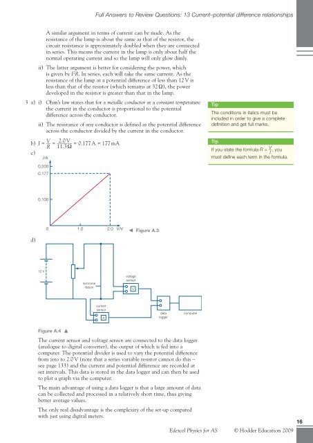
3 a) i) Ohm’s law states that for a metallic conduc<strong>to</strong>r at a constant temperature<br />
the current in the conduc<strong>to</strong>r is proportional <strong>to</strong> the potential<br />
difference across the conduc<strong>to</strong>r.<br />
ii) The resistance of any conduc<strong>to</strong>r is defined as the potential difference<br />
across the conduc<strong>to</strong>r divided by the current in the conduc<strong>to</strong>r.<br />
b) I = V<br />
__<br />
c)<br />
d)<br />
I/A<br />
0.200<br />
0.177<br />
0.100<br />
12 V<br />
R =<br />
______ 2.0 V<br />
= 0.177 A = 177 mA<br />
11.3 Ω<br />
0 1.0 2.0 V/V � Figure A.3<br />
Figure A.4 �<br />
nichrome<br />
ribbon<br />
current<br />
sensor<br />
A<br />
voltage<br />
sensor<br />
V<br />
data<br />
logger<br />
computer<br />
The current sensor and voltage sensor are connected <strong>to</strong> the data logger<br />
(analogue <strong>to</strong> digital converter), the output of which is fed in<strong>to</strong> a<br />
computer. The potential divider is used <strong>to</strong> vary the potential difference<br />
from zero <strong>to</strong> 2.0 V (note that a series variable resis<strong>to</strong>r cannot do this –<br />
see page 133) and the current and potential difference are recorded at<br />
set intervals. This data is s<strong>to</strong>red in the data logger and can then be used<br />
<strong>to</strong> plot a graph via the computer.<br />
The main advantage of using a data logger is that a large amount of data<br />
can be collected and processed in a relatively short time, thus giving<br />
better average values.<br />
The only real disadvantage is the complexity of the set-up compared<br />
with just using digital meters.<br />
Tip<br />
The conditions in italics must be<br />
included in order <strong>to</strong> give a complete<br />
definition and get full marks.<br />
Tip<br />
If you state the formula R = V __ , you<br />
I<br />
must define each term in the formula.<br />
Edexcel Physics for AS © <strong>Hodder</strong> Education 2009<br />
16