Full Answers to Review Questions - Hodder Plus Home
Full Answers to Review Questions - Hodder Plus Home
Full Answers to Review Questions - Hodder Plus Home

Create successful ePaper yourself
Turn your PDF publications into a flip-book with our unique Google optimized e-Paper software.
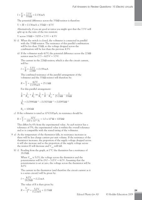
I = V __ = _____ 7.5 V<br />
= 0.136 mA<br />
R 55 kΩ<br />
The potential difference across the 33 kΩ resis<strong>to</strong>r is therefore:<br />
V = IR = 0.136 mA × 33 kΩ = 4.5 V<br />
Alternatively, if you are good at ratios you might spot that the 7.5 V will<br />
split up in the ratio of the two resis<strong>to</strong>rs:<br />
V across 33 kΩ = 33/55 × 7.5 V = 4.5 V<br />
b) i) When the switch is closed, the voltmeter is connected in parallel<br />
with the 33 kΩ resis<strong>to</strong>r. The resistance of this parallel combination<br />
will be less than 33 kΩ, so the voltage dropped across the<br />
combination will be less than the previous 4.5 V.<br />
ii) If the voltmeter reads 4.0 V, the potential difference across the 22 kΩ<br />
resis<strong>to</strong>r must be (7.5 − 4.0) V = 3.5 V.<br />
The current in the 22 kΩ resis<strong>to</strong>r, which is also the circuit current,<br />
will be:<br />
I = V __ = _____ 3.5 V<br />
= 0.159 mA<br />
R 22 kΩ<br />
The combined resistance of the parallel arrangement of the<br />
voltmeter and the 33 kΩ resis<strong>to</strong>r will therefore be:<br />
R = V<br />
__<br />
I<br />
= _________ 4.0 V<br />
= 25.1 kΩ<br />
0.159 mA<br />
For this parallel arrangement:<br />
1 __ =<br />
R 1 ___ +<br />
R33 1 ___ ⇒<br />
RV 1 ___ =<br />
RV 1 __ –<br />
R 1 ___ = _______ 1<br />
– ______ 1<br />
R33 25.1 kΩ 33 kΩ<br />
1 ___ = 0.0398 kΩ<br />
RV −1 − 0.0303 kΩ−1 = 0.0095 kΩ−1 R V = 106 kΩ<br />
c) If the voltmeter is rated as 10 V/100 μA, its resistance should be:<br />
R = V<br />
__<br />
I =<br />
10 V<br />
___________<br />
100 × 10 −6 A = 1.0 × 10⁵ Ω = 100 kΩ<br />
This differs by 6% from the experimental value. As each resis<strong>to</strong>r has a<br />
<strong>to</strong>lerance of 5%, the experimental value is within the overall <strong>to</strong>lerance<br />
and so is compatible with the stated rating of the voltmeter.<br />
9 a) As the temperature of the thermis<strong>to</strong>r falls, its resistance increases as<br />
there will be less charge carriers per unit volume. If the resistance of the<br />
thermis<strong>to</strong>r increases, the proportion of the supply voltage dropped across<br />
it will also increase and so the proportion of the supply voltage across<br />
the resis<strong>to</strong>r R will decrease and V out will fall.<br />
b) i) Reading from the graph, at 0 8C the thermis<strong>to</strong>r has a resistance of<br />
18.0 kΩ.<br />
When V out is 5.0 V, the voltage across the thermis<strong>to</strong>r and the<br />
potentiometer will be (9.0 − 5.0) V = 4.0 V. Assuming that the<br />
potentiometer is set at zero, the voltage across the thermis<strong>to</strong>r will be<br />
4.0 V.<br />
The current in the thermis<strong>to</strong>r (and therefore the circuit current as it<br />
is a series circuit) will be given by:<br />
I =<br />
_______ 4.0 V<br />
= 0.22 mA<br />
18.0 kΩ<br />
The value of R is then given by:<br />
R = V ____ out<br />
I<br />
= ________ 5.0 V<br />
= 22.5 kΩ<br />
0.22 mA<br />
<strong>Full</strong> <strong>Answers</strong> <strong>to</strong> <strong>Review</strong> <strong>Questions</strong>: 15 Electric circuits<br />
Edexcel Physics for AS © <strong>Hodder</strong> Education 2009<br />
24