VVER-1000 Coolant Transient Benchmark - OECD Nuclear Energy ...
VVER-1000 Coolant Transient Benchmark - OECD Nuclear Energy ...
VVER-1000 Coolant Transient Benchmark - OECD Nuclear Energy ...

Create successful ePaper yourself
Turn your PDF publications into a flip-book with our unique Google optimized e-Paper software.
CFD RESULTS AND DISCUSSION<br />
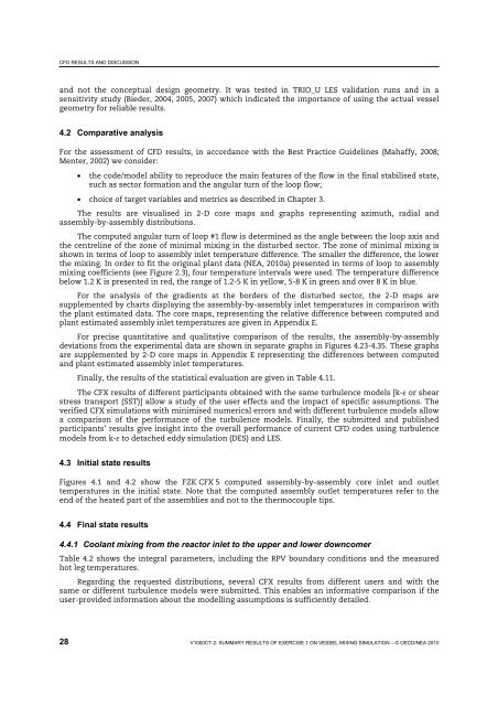
and not the conceptual design geometry. It was tested in TRIO_U LES validation runs and in a<br />
sensitivity study (Bieder, 2004, 2005, 2007) which indicated the importance of using the actual vessel<br />
geometry for reliable results.<br />
4.2 Comparative analysis<br />
For the assessment of CFD results, in accordance with the Best Practice Guidelines (Mahaffy, 2008;<br />
Menter, 2002) we consider:<br />
• the code/model ability to reproduce the main features of the flow in the final stabilised state,<br />
such as sector formation and the angular turn of the loop flow;<br />
• choice of target variables and metrics as described in Chapter 3.<br />
The results are visualised in 2-D core maps and graphs representing azimuth, radial and<br />
assembly-by-assembly distributions.<br />
The computed angular turn of loop #1 flow is determined as the angle between the loop axis and<br />
the centreline of the zone of minimal mixing in the disturbed sector. The zone of minimal mixing is<br />
shown in terms of loop to assembly inlet temperature difference. The smaller the difference, the lower<br />
the mixing. In order to fit the original plant data (NEA, 2010a) presented in terms of loop to assembly<br />
mixing coefficients (see Figure 2.3), four temperature intervals were used. The temperature difference<br />
below 1.2 K is presented in red, the range of 1.2-5 K in yellow, 5-8 K in green and over 8 K in blue.<br />
For the analysis of the gradients at the borders of the disturbed sector, the 2-D maps are<br />
supplemented by charts displaying the assembly-by-assembly inlet temperatures in comparison with<br />
the plant estimated data. The core maps, representing the relative difference between computed and<br />
plant estimated assembly inlet temperatures are given in Appendix E.<br />
For precise quantitative and qualitative comparison of the results, the assembly-by-assembly<br />
deviations from the experimental data are shown in separate graphs in Figures 4.23-4.35. These graphs<br />
are supplemented by 2-D core maps in Appendix E representing the differences between computed<br />
and plant estimated assembly inlet temperatures.<br />
Finally, the results of the statistical evaluation are given in Table 4.11.<br />
The CFX results of different participants obtained with the same turbulence models [k-ε or shear<br />
stress transport (SST)] allow a study of the user effects and the impact of specific assumptions. The<br />
verified CFX simulations with minimised numerical errors and with different turbulence models allow<br />
a comparison of the performance of the turbulence models. Finally, the submitted and published<br />
participants’ results give insight into the overall performance of current CFD codes using turbulence<br />
models from k-ε to detached eddy simulation (DES) and LES.<br />
4.3 Initial state results<br />
Figures 4.1 and 4.2 show the FZK CFX 5 computed assembly-by-assembly core inlet and outlet<br />
temperatures in the initial state. Note that the computed assembly outlet temperatures refer to the<br />
end of the heated part of the assemblies and not to the thermocouple tips.<br />
4.4 Final state results<br />
4.4.1 <strong>Coolant</strong> mixing from the reactor inlet to the upper and lower downcomer<br />
Table 4.2 shows the integral parameters, including the RPV boundary conditions and the measured<br />
hot leg temperatures.<br />
Regarding the requested distributions, several CFX results from different users and with the<br />
same or different turbulence models were submitted. This enables an informative comparison if the<br />
user-provided information about the modelling assumptions is sufficiently detailed.<br />
28 V<strong>1000</strong>CT-2: SUMMARY RESULTS OF EXERCISE 1 ON VESSEL MIXING SIMULATION – © <strong>OECD</strong>/NEA 2010